d11 = conv. heat note: the red j4.6 +24vac output / j1.7 2
TRANSCRIPT

D11 = Conv. HeatJ4.6 +24VAC Output / J1.7 -24VDC & J5.5 +24VDC Input Trigger
D21 = Drive@SpeedInternal Outputs allowing J4.6 Fed by J4.4 +24VAC J3.5 -24VDC Input Trigger
D31 = Oven OnJ4.3 +24VAC & J6.3 +24VDC OutputJ1.1 -24VDC Input Trigger
D41 = Cooling FanJ5.6 +24VDC OutputJ1.8 -24VDC Input Trigger
D51 = VentJ8.10 +24VDC / J1.17 -24VDC Input Trigger
D61 = LightsJ5.8 +24VDC Output / J1.11 -24VDC Input Trigger
Outputs without LEDs:
Boiler Overtemp J2.4 +24VDC Output / J6.6 +24VDC Input Trigger
Door Closed J2.1 +24VDC Output / J5.5 +24VDC Input Trigger
1 1
1
1
1 1 1
1
D31
D21
D11
D41
D51
D61
D9
D101
D81
D71
D8
2 2
Note: The red momentary button next to D101 manually opens the drain
D9 = Quench ValveJ8.7 -24VDC OutputJ1.16 -24VDC Input Trigger
D101 = Boiler DrainJ8.8 0V & J8.9 +24VDC Output. (When the drain is closed, J8.8 is +24VDC and J8.9 is 0V )
J1.15 -24VDC Input Trigger
D81 = Fill EnableJ8.6 & J8.5 Outputs Fed by J8.4 +24VDC & J8.3 +24VDC / J1.14 -24VDC Input Trigger
D71 = Boiler HeatJ6.5 Output fed by J6.4 +24VAC / J1.12 -24VDC Input Trigger
D8 = Delime PumpJ8.11 -24VDC OutputJ1.13 -24VDC Input Trigger
Outputs without LEDs:
Low Water J2.5 +24VDC Output / J8.4 +24VDC Input

Green LEDs glow to show Outputs
LED 14 = Boiler Drain OpenJ3.10 -24VDC Output to the Relay Board to enable the J8.9 Output to Open the Drain Valve
LED 17 = Spare OutputJ3.5 not used
LED 10 = Boiler Heat OnJ4.6 -24VDC Output to the Relay Board to enable the J6.5 Output, Boiler Main On +24VAC signal
LED 11 = Call for DelimeJ4.4 -24VDC (Flashing) Output to the Delime Lamp signals the Delime Timer has expired. The Timer is set at the R1 potentiometer, for 30, 60 or 90 hours between Delime calls. 30 is fully counterclockwise and 90 is fully clockwise
LED 12 = Steam On Demand OnJ4.3 -24VDC Output to the Steam On Demand “Active” Light, indicating the Steam on Demand cycle is active
LED 13 = Convection Heat OnJ4.2 -24VDC Output to the Relay Board to enable the J4.6 Main Burner On +24VAC signal
LED 16 = Delime PumpJ1.5 -24VDC Output to the Relay Board to enable the J8.11 Delime Chemical Pump -24VDC signal
LED 15 = Boiler Fill EnableJ1.3 -24VDC Output to the Relay Board when the Low Water Signal is present (LED 8) or the Heat, Steam or Hot Air is Selected
Amber LEDs glow to show Inputs
LED 1 = Flush Disable (&Combi Preheat)J1.2 -24VDC Input from Flush Disable T-stat that opens at 158˚F. LED Off = Flush Disabled
LED 2 = Combi ModeJ3.1 -24VDC Input from the Mode Switch, SW1 that indicates the selection of Combi Mode
LED 3 = Steam ModeJ3.2 -24VDC Input from the Mode Switch, SW1 that indicates the selection of Steam Mode
LED 4 = Steam On Demand CallJ3.7 -24VDC Input from the Steam on Demand Button, SW10 that indicates the selection of Steam On Demand
LED 5 = Spare InputJ3.8 not used
LED 6 = Heat DemandJ4.1 -24VDC Input from the Temperature Controller, TC1 that indicates a call for heat
LED 7 = Boiler High LimitJ4.5 +24VDC Input from the Relay Board triggered by the boiler high limit signal to the Relay Board at J6.6
LED 8 = Low WaterJ4.8 +24VDC Input from the Relay Board triggered by the Low Float Signal to J8.4 (Input Triggers the Panel's Fill Light Also)
LED 9 = Hot Air ModeJ3.6 -24VDC Input from the Mode Switch, SW1 that indicates the selection of Hot Air Mode
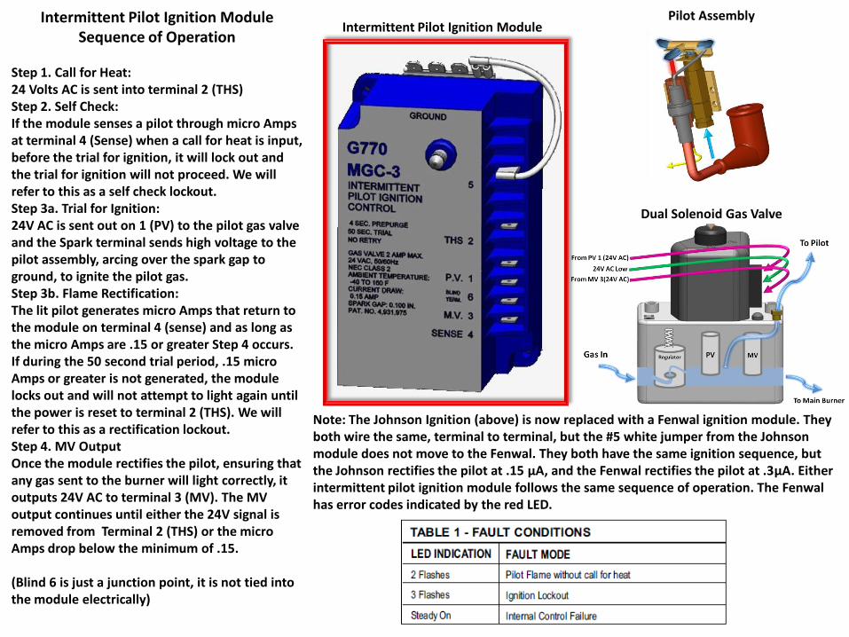
Intermittent Pilot Ignition Module Sequence of Operation
Step 1. Call for Heat:24 Volts AC is sent into terminal 2 (THS)Step 2. Self Check:If the module senses a pilot through micro Amps at terminal 4 (Sense) when a call for heat is input, before the trial for ignition, it will lock out and the trial for ignition will not proceed. We will refer to this as a self check lockout.Step 3a. Trial for Ignition:24V AC is sent out on 1 (PV) to the pilot gas valve and the Spark terminal sends high voltage to the pilot assembly, arcing over the spark gap to ground, to ignite the pilot gas.Step 3b. Flame Rectification:The lit pilot generates micro Amps that return to the module on terminal 4 (sense) and as long as the micro Amps are .15 or greater Step 4 occurs. If during the 50 second trial period, .15 micro Amps or greater is not generated, the module locks out and will not attempt to light again until the power is reset to terminal 2 (THS). We will refer to this as a rectification lockout.Step 4. MV OutputOnce the module rectifies the pilot, ensuring that any gas sent to the burner will light correctly, it outputs 24V AC to terminal 3 (MV). The MV output continues until either the 24V signal is removed from Terminal 2 (THS) or the micro Amps drop below the minimum of .15.
(Blind 6 is just a junction point, it is not tied into the module electrically)
Note: The Johnson Ignition (above) is now replaced with a Fenwal ignition module. They both wire the same, terminal to terminal, but the #5 white jumper from the Johnson module does not move to the Fenwal. They both have the same ignition sequence, but the Johnson rectifies the pilot at .15 μA, and the Fenwal rectifies the pilot at .3μA. Either intermittent pilot ignition module follows the same sequence of operation. The Fenwal has error codes indicated by the red LED.
Intermittent Pilot Ignition ModulePilot Assembly
Dual Solenoid Gas Valve

Front BackDiagnostic Mode:
Press Start Key for 5 Seconds during Diagnostic Countdown
Inputs and OutputsProgramming Mode: Press + Key for 5 Seconds then – Key for 5 Seconds during Diagnostic Countdown (The Mode Key toggles between
Programs/Values and + or – raises or lowers the current selection)Example: P5 01 is program 5 and 01 indicates F (Fahrenheit) is set.
Error Codes

Fan Speed Gentle
Fan Speed Low
Fan Speed High
Fan Speed Turbo
To Pin 3 -24 VDC 0 VDC -24 VDC 0 VDC
To Pin 4 -24 VDC -24 VDC 0 VDC 0 VDC
50.0
235 Volts AC 3Ø 2.7 Amps
Forward Turbo:(Read from 24V DC to Pin 3 and from 24V DC to Pin 4)

Fan Speed Gentle
Fan Speed Low
Fan Speed High
Fan Speed Turbo
To Pin 3 -24 VDC 0 VDC -24 VDC 0 VDC
To Pin 4 -24 VDC -24 VDC 0 VDC 0 VDC
40.0
215 Volts AC 3Ø 2.3 Amps
Forward High:(Read from 24V DC to Pin 3 and from 24V DC to Pin 4)

Fan Speed Gentle
Fan Speed Low
Fan Speed High
Fan Speed Turbo
To Pin 3 -24 VDC 0 VDC -24 VDC 0 VDC
To Pin 4 -24 VDC -24 VDC 0 VDC 0 VDC
30.0
190 Volts AC 3Ø 2.1 Amps
Forward Low:(Read from 24V DC to Pin 3 and from 24V DC to Pin 4)

Fan Speed Gentle
Fan Speed Low
Fan Speed High
Fan Speed Turbo
To Pin 3 -24 VDC 0 VDC -24 VDC 0 VDC
To Pin 4 -24 VDC -24 VDC 0 VDC 0 VDC
20.0
155 Volts AC 3Ø 1.9 Amps
Forward Gentle:(Read from 24V DC to Pin 3 and from 24V DC to Pin 4)

50.0
235 Volts AC 3Ø 2.7 Amps
Forward

50.0
235 Volts AC 3Ø 2.7 Amps
Reverse
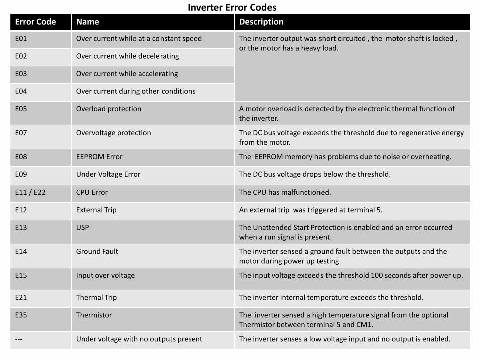
Error Code Name Description
E01 Over current while at a constant speed The inverter output was short circuited , the motor shaft is locked , or the motor has a heavy load.
E02 Over current while decelerating
E03 Over current while accelerating
E04 Over current during other conditions
E05 Overload protection A motor overload is detected by the electronic thermal function of the inverter.
E07 Overvoltage protection The DC bus voltage exceeds the threshold due to regenerative energy from the motor.
E08 EEPROM Error The EEPROM memory has problems due to noise or overheating.
E09 Under Voltage Error The DC bus voltage drops below the threshold.
E11 / E22 CPU Error The CPU has malfunctioned.
E12 External Trip An external trip was triggered at terminal 5.
E13 USP The Unattended Start Protection is enabled and an error occurred when a run signal is present.
E14 Ground Fault The inverter sensed a ground fault between the outputs and the motor during power up testing.
E15 Input over voltage The input voltage exceeds the threshold 100 seconds after power up.
E21 Thermal Trip The inverter internal temperature exceeds the threshold.
E35 Thermistor The inverter sensed a high temperature signal from the optional Thermistor between terminal 5 and CM1.
--- Under voltage with no outputs present The inverter senses a low voltage input and no output is enabled.
Inverter Error Codes
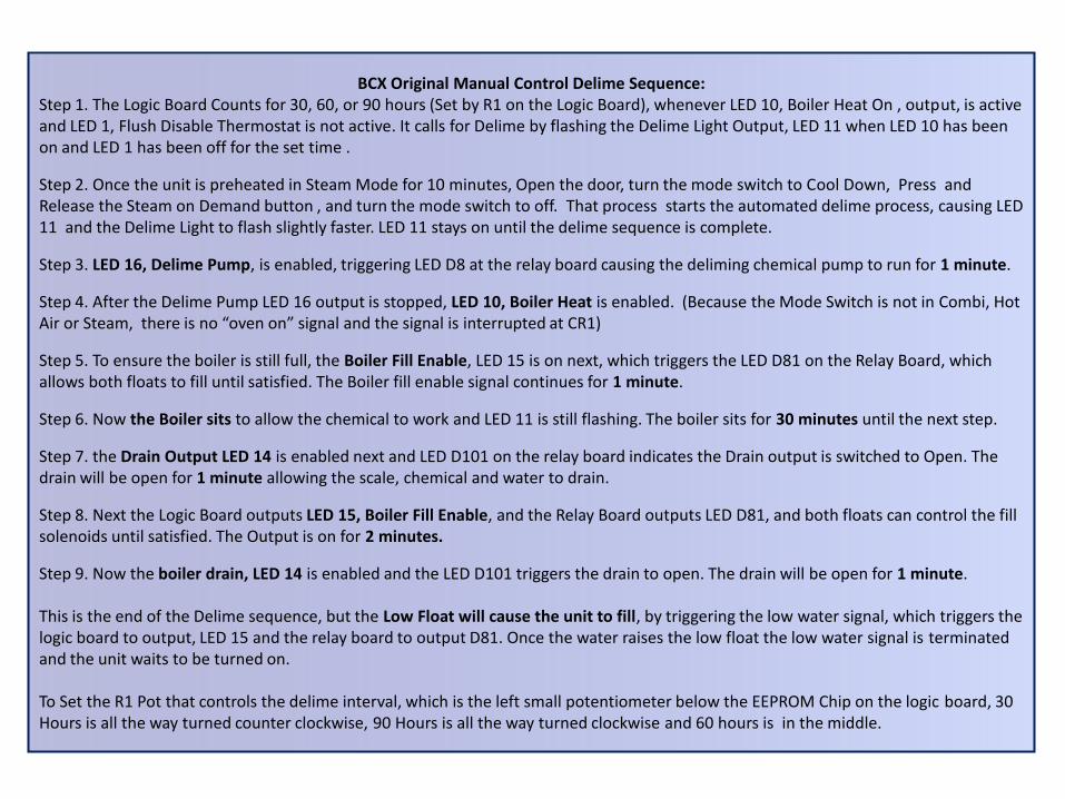
BCX Original Manual Control Delime Sequence: Step 1. The Logic Board Counts for 30, 60, or 90 hours (Set by R1 on the Logic Board), whenever LED 10, Boiler Heat On , output, is active and LED 1, Flush Disable Thermostat is not active. It calls for Delime by flashing the Delime Light Output, LED 11 when LED 10 has been on and LED 1 has been off for the set time .
Step 2. Once the unit is preheated in Steam Mode for 10 minutes, Open the door, turn the mode switch to Cool Down, Press and Release the Steam on Demand button , and turn the mode switch to off. That process starts the automated delime process, causing LED 11 and the Delime Light to flash slightly faster. LED 11 stays on until the delime sequence is complete.
Step 3. LED 16, Delime Pump, is enabled, triggering LED D8 at the relay board causing the deliming chemical pump to run for 1 minute.
Step 4. After the Delime Pump LED 16 output is stopped, LED 10, Boiler Heat is enabled. (Because the Mode Switch is not in Combi, Hot Air or Steam, there is no “oven on” signal and the signal is interrupted at CR1)
Step 5. To ensure the boiler is still full, the Boiler Fill Enable, LED 15 is on next, which triggers the LED D81 on the Relay Board, which allows both floats to fill until satisfied. The Boiler fill enable signal continues for 1 minute.
Step 6. Now the Boiler sits to allow the chemical to work and LED 11 is still flashing. The boiler sits for 30 minutes until the next step.
Step 7. the Drain Output LED 14 is enabled next and LED D101 on the relay board indicates the Drain output is switched to Open. The drain will be open for 1 minute allowing the scale, chemical and water to drain.
Step 8. Next the Logic Board outputs LED 15, Boiler Fill Enable, and the Relay Board outputs LED D81, and both floats can control the fill solenoids until satisfied. The Output is on for 2 minutes.
Step 9. Now the boiler drain, LED 14 is enabled and the LED D101 triggers the drain to open. The drain will be open for 1 minute.
This is the end of the Delime sequence, but the Low Float will cause the unit to fill, by triggering the low water signal, which triggers the logic board to output, LED 15 and the relay board to output D81. Once the water raises the low float the low water signal is terminated and the unit waits to be turned on.
To Set the R1 Pot that controls the delime interval, which is the left small potentiometer below the EEPROM Chip on the logic board, 30 Hours is all the way turned counter clockwise, 90 Hours is all the way turned clockwise and 60 hours is in the middle.