d104161x012 fisher d3 control valve with gen 2 easy … fisher™ d3 control valve with gen 2...
TRANSCRIPT
www.Fisher.com
Fisher™ D3 Control Valve with Gen 2 easy-Drive™
Electric Actuator
ContentsIntroduction 1. . . . . . . . . . . . . . . . . . . . . . . . . . . . . . . . .
Scope of Manual 1. . . . . . . . . . . . . . . . . . . . . . . . . . . . .Description 3. . . . . . . . . . . . . . . . . . . . . . . . . . . . . . . . .Specifications 3. . . . . . . . . . . . . . . . . . . . . . . . . . . . . . .Educational Services 3. . . . . . . . . . . . . . . . . . . . . . . . .
Installation 3. . . . . . . . . . . . . . . . . . . . . . . . . . . . . . . . . .Special Instructions for “Safe Use” and Installations
in Hazardous Locations 4. . . . . . . . . . . . . . . . . . . . .Startup Overview 5. . . . . . . . . . . . . . . . . . . . . . . . . . . .Default Input Signals 10. . . . . . . . . . . . . . . . . . . . . . . .Configuration 10. . . . . . . . . . . . . . . . . . . . . . . . . . . . . .
Input Configuration 10. . . . . . . . . . . . . . . . . . . . .Changing the Inputs from Default Settings 10. .
Modbus Setup 10. . . . . . . . . . . . . . . . . . . . . . . . . . . . .Connecting using the Fisher easy-Drive
configuration software 11. . . . . . . . . . . . . . . .Initial Setup 11. . . . . . . . . . . . . . . . . . . . . . . . . . . .Calibration Instructions 12. . . . . . . . . . . . . . . . . .Licensing 15. . . . . . . . . . . . . . . . . . . . . . . . . . . . . .Startup 17. . . . . . . . . . . . . . . . . . . . . . . . . . . . . . . .
Troubleshooting 18. . . . . . . . . . . . . . . . . . . . . . . . . . . . .Setting the Valve Flow Adjuster 19. . . . . . . . . . . . . . . .Maintenance 20. . . . . . . . . . . . . . . . . . . . . . . . . . . . . . . .
Valve Plug and Seat Ring Maintenance 22. . . . . . . . .Packing Maintenance 24. . . . . . . . . . . . . . . . . . . . . . . .
Parts Ordering 26. . . . . . . . . . . . . . . . . . . . . . . . . . . . . . .
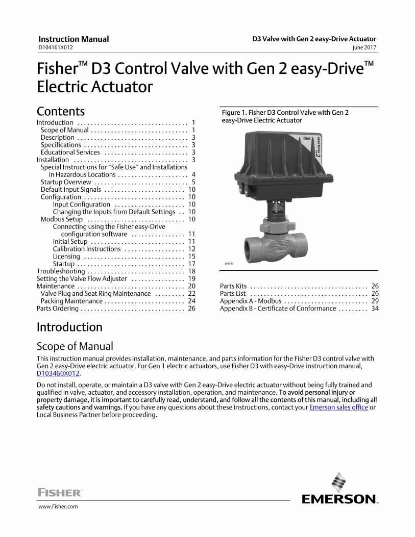
Figure 1. Fisher D3 Control Valve with Gen 2 easy-Drive Electric Actuator
W9797
Parts Kits 26. . . . . . . . . . . . . . . . . . . . . . . . . . . . . . . . . . .Parts List 26. . . . . . . . . . . . . . . . . . . . . . . . . . . . . . . . . . .Appendix A - Modbus 29. . . . . . . . . . . . . . . . . . . . . . . . .Appendix B - Certificate of Conformance 34. . . . . . . . .
Introduction
Scope of ManualThis instruction manual provides installation, maintenance, and parts information for the Fisher D3 control valve withGen 2 easy-Drive electric actuator. For Gen 1 electric actuators, use Fisher D3 with easy-Drive instruction manual,D103460X012.
Do not install, operate, or maintain a D3 valve with Gen 2 easy-Drive electric actuator without being fully trained andqualified in valve, actuator, and accessory installation, operation, and maintenance. To avoid personal injury orproperty damage, it is important to carefully read, understand, and follow all the contents of this manual, including allsafety cautions and warnings. If you have any questions about these instructions, contact your Emerson sales office orLocal Business Partner before proceeding.
Instruction ManualD104161X012
D3 Valve with Gen 2 easy-Drive ActuatorJune 2017

Instruction ManualD104161X012
D3 Valve with Gen 2 easy-Drive ActuatorJune 2017
2
Table 1. Specifications
Valve Body Sizes, End Connection Styles, and PortDiameters(1)
VALVESIZE,NPS
PORTDIAMETER,
(INCHES)
THREADEDRAISED FACE
(RF) FLANGED
CL900 CL600
1 0.375, 0.75, 1 X X
2 0.375, 0.75, 1 X X
X = Available construction.
Maximum Inlet Pressures and Temperatures(1)
VALVE BODY SIZE
MAXIMUM INLETPRESSURE
TEMPERATURE RANGE
bar (psig) �C (�F)
NPS 1 NPTCL900
155 (2250) -46 to 93 (-50 to 200)
150 (2185) 93 to 149 (200 to 300)
NPS 2 NPTCL900
155 (2250) -46 to 93 (-50 to 200)
150 (2185) 93 to 149 (200 to 300)
NPS 1 RFCL600
103 (1500) -46 to 93 (-50 to 200)
100 (1455) 93 to 149 (200 to 300)
NPS 2 RFCL600
103 (1500) -46 to 93 (-50 to 200)
100 (1455) 93 to 149 (200 to 300)
Maximum Shutoff Pressure Drops(1)
MAXIMUM �P BAR (PSI) PER PORT SIZE
Port Size, mm (inch)
9.5 (0.375) 19.1 (0.75) 25.4 (1.00)
Flow Up 155 (2250) 105 (1518) 75 (1089)
Flow Down 155 (2250) 155 (2250) 130 (1889)
Shutoff Classification per ANSI/FCI 70‐2 and IEC 60534‐4
Class IV
Flow Characteristic / Valve Plug Style
Equal percentage / Micro‐Form Valve Plug
Maximum Travel
15 mm (0.6 inch)
Material Temperature Capabilities(1)
Valve Body Assembly: Standard Bonnet O-Ring: -40 to 135°C (-40 to 275°F)
Electric Actuator Assembly: -20 to 70°C (-4 to 158°F), < 90% non-condensing humidity
Flow Direction
Flow up (standard), Flow down (optional)
Available Actuator Configurations
On/off (snap acting)Positioning (flow or pressure control)
Power Requirements
9 - 30VDC, minimum 4 amp power supply required(fuse to 5 amps)
Maximum Current Draw
4 amps
Idle Current Draw
15 mA at 24VDC, 25 mA at 12VDC
Conduit Connections
Two 3/4 NPT connections
Stroke Length
FloPro controlled between 10mm (0.4 inch) and15mm (0.6 inch)
Nominal Stroke Speed(2)
3.9 mm/s (0.15 inch/s) at 24 VDC2.2 mm/s (0.09 inch/s) at 12 VDC
Hazardous Area Approvals
CSA (C/US): ExplosionProof Class I, Division 1,Groups C and D, T6, Ex d IIA T6, Class I, Zone 1, AEx dIIA T6ATEX Flameproof - Gas:
II 2 G, Ex db IIA T6IECEx Flameproof - Gas: Ex db IIA T6
Enclosure Rating
Type 4X and IP66
Duty Cycle
50% maximum
Enclosure Material
Cast aluminum alloy with powder coat paint
Approximate Weight:
18 - 27 kg (39 - 60 lbs), depending upon construction
1. The pressure or temperature limits in the referenced tables and any applicable ASME code limitations should not be exceeded.2. 10% variation can be expected, based on temperature and pressure of application.

Instruction ManualD104161X012
D3 Valve with Gen 2 easy-Drive ActuatorJune 2017
3
DescriptionThe Fisher D3 with easyDrive electric actuator technology (figure 1) is a globe valve with electric actuator specificallydesigned for upstream, low power applications. The easyDrive operates with 12 or 24VDC in either on/off orPositioning configurations.
The on/off configuration has 2 different states; opened or closed, which are ideal for dump or snap acting applications.The Positioning configuration extends the functionality to intermediate positions for flow and pressure controlapplications.
SpecificationsTable 1 lists specifications for the D3 control valve. Some of the specifications for a given control valve as it originallycomes from the factory are stamped on a nameplate located on the lower actuator housing.
Educational ServicesFor information on available courses for the Fisher D3 control valve with Gen 2 easy-Drive electric actuator, as well as avariety of other products, contact:
Emerson Automation SolutionsEducational Services - RegistrationPhone: 1-641-754-3771 or 1-800-338-8158E-mail: [email protected]/fishervalvetraining
Installation
WARNING
Always wear protective gloves, clothing, and eyewear when performing any installation operations to avoid personalinjury.
To avoid personal injury or property damage caused by bursting of pressure‐retaining parts or by uncontrolled processfluid, be certain the service conditions do not exceed the limits shown on the valve nameplate and in table 1. Usepressure‐relieving devices required by government or accepted industry codes and good engineering practices.
Check with your process or safety engineer for any additional measures that must be taken to protect against processmedia.
If installing into an existing application, also refer to the WARNING at the beginning of the Maintenance section in thisinstruction manual.
WARNING
For explosionproof applications, ensure the actuator cover is properly bolted before applying power to the actuator.Personal injury or property damage may result from fire or explosion if power is applied to the actuator with the coverremoved in a hazardous area.
For explosion‐proof applications, install rigid metal conduit and a conduit seal no more than 457 mm (18 inches) from theactuator. Personal injury or property damage may result from explosion if the seal is not installed.
Select wiring and/or cable glands that are rated for the environment of use (such as hazardous area, ingress protection, andtemperature). Failure to use properly rated wiring and/or cable glands can result in personal injury or property damagefrom fire or explosion.
Instruction ManualD104161X012
D3 Valve with Gen 2 easy-Drive ActuatorJune 2017
4
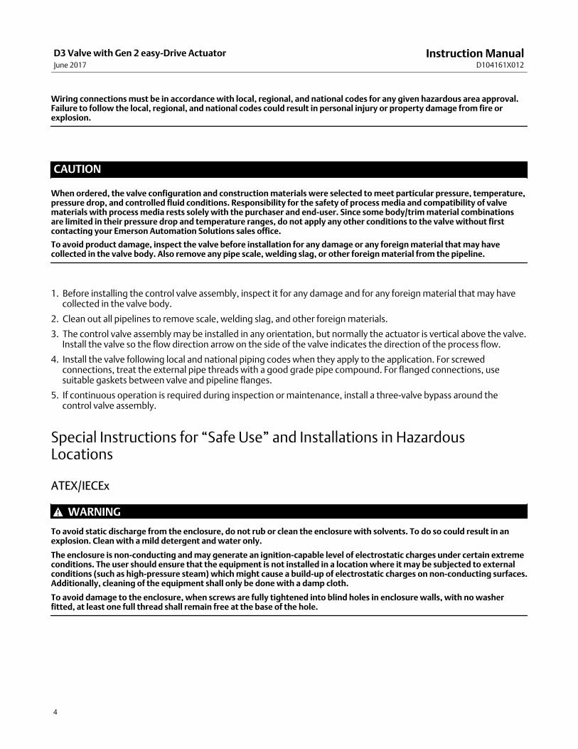
Wiring connections must be in accordance with local, regional, and national codes for any given hazardous area approval.Failure to follow the local, regional, and national codes could result in personal injury or property damage from fire orexplosion.
CAUTION
When ordered, the valve configuration and construction materials were selected to meet particular pressure, temperature,pressure drop, and controlled fluid conditions. Responsibility for the safety of process media and compatibility of valvematerials with process media rests solely with the purchaser and end‐user. Since some body/trim material combinationsare limited in their pressure drop and temperature ranges, do not apply any other conditions to the valve without firstcontacting your Emerson Automation Solutions sales office.
To avoid product damage, inspect the valve before installation for any damage or any foreign material that may havecollected in the valve body. Also remove any pipe scale, welding slag, or other foreign material from the pipeline.
1. Before installing the control valve assembly, inspect it for any damage and for any foreign material that may havecollected in the valve body.
2. Clean out all pipelines to remove scale, welding slag, and other foreign materials.
3. The control valve assembly may be installed in any orientation, but normally the actuator is vertical above the valve.Install the valve so the flow direction arrow on the side of the valve indicates the direction of the process flow.
4. Install the valve following local and national piping codes when they apply to the application. For screwedconnections, treat the external pipe threads with a good grade pipe compound. For flanged connections, usesuitable gaskets between valve and pipeline flanges.
5. If continuous operation is required during inspection or maintenance, install a three‐valve bypass around thecontrol valve assembly.
Special Instructions for “Safe Use” and Installations in HazardousLocations
ATEX/IECEx
WARNING
To avoid static discharge from the enclosure, do not rub or clean the enclosure with solvents. To do so could result in anexplosion. Clean with a mild detergent and water only.
The enclosure is nonconducting and may generate an ignitioncapable level of electrostatic charges under certain extremeconditions. The user should ensure that the equipment is not installed in a location where it may be subjected to externalconditions (such as highpressure steam) which might cause a buildup of electrostatic charges on nonconducting surfaces.Additionally, cleaning of the equipment shall only be done with a damp cloth.
To avoid damage to the enclosure, when screws are fully tightened into blind holes in enclosure walls, with no washerfitted, at least one full thread shall remain free at the base of the hole.

Instruction ManualD104161X012
D3 Valve with Gen 2 easy-Drive ActuatorJune 2017
5
Startup Overview
Figure 2. Flowchart
PREPARE PER INSTRUCTIONSIN INSTALLATION SECTION
POSITIONING ORON/OFF?
POSITIONINGON/OFF
WIRE PER DIAGRAM FOR L2e WIRE PER DIAGRAM FOR 4-20 mA
YES
YES
NO
NO
ARE YOU USINGModbus?
FIRST TIME USINGModbus?
CONNECT USB-TO-Modbus CONVERTERTO INTERNET CONNECTED COMPUTER
CONNECT VIA Modbus TO VALVE ANDMONITOR DESIRED REGISTERS
FOLLOW DRIVER INSTALLATIONINSTRUCTIONS FOR YOUR DEVICE
INSTALL easy-Drive CONFIGURATION ORModbus MASTER SOFTWARE
UNIT IS READY FOR OPERATION

Instruction ManualD104161X012
D3 Valve with Gen 2 easy-Drive ActuatorJune 2017
6
Figure 3. Fisher D3 Valve with Gen 2 easy-Drive Actuator Wiring Diagram
FIELD WIRING CONNECTIONS
MOTOR / GEARBOX ASSY(GE84238)
CONTROLLER
POWER AND CONTROL TERMINAL
GE47302-7
TOP VIEW CONTROLLER
Power Requirements
Ensure a stable DC power source is available, maintaining less than 5% ripple and sufficiently surge protected for theapplication. A 4 amp (minimum) power supply is required.
Wiring Instructions1. Observe local wiring requirements for hazardous location usage.
2. Conduit seals within 450 mm (18 inches) of the enclosure port are required for explosionproof installation.
3. 18AWG (0.52mm2) to 12AWG (3.31mm2) wire size required.
4. Fuse system to 5A.
5. Connect enclosure and analog signal shields.
6. Ensure power is turned off before connecting the wires.
Power
1. Connect 12 or 24 VDC reference to: –
2. Connect 12 or 24 VDC positive to: +
3. Be sure to tighten terminals sufficiently to ensure solid mechanical connection.

Instruction ManualD104161X012
D3 Valve with Gen 2 easy-Drive ActuatorJune 2017
7
Figure 4. Wiring - Analog Input
Figure 5. Wiring - L2e

Instruction ManualD104161X012
D3 Valve with Gen 2 easy-Drive ActuatorJune 2017
8
Figure 6. Wiring - Single Dry Contact
Figure 7. Wiring - Modbus Input
Instruction ManualD104161X012
D3 Valve with Gen 2 easy-Drive ActuatorJune 2017
9
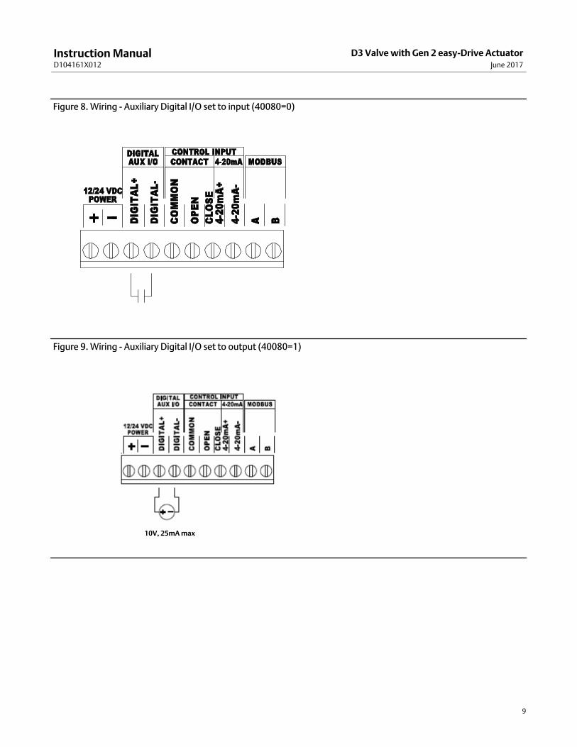
Figure 8. Wiring - Auxiliary Digital I/O set to input (40080=0)
Figure 9. Wiring - Auxiliary Digital I/O set to output (40080=1)
10V, 25mA max
Instruction ManualD104161X012
D3 Valve with Gen 2 easy-Drive ActuatorJune 2017
10
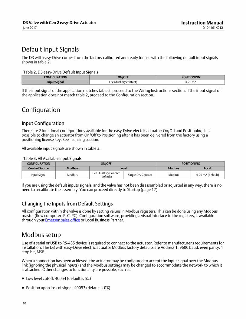
Default Input SignalsThe D3 with easyDrive comes from the factory calibrated and ready for use with the following default input signalsshown in table 2.
Table 2. D3 easy-Drive Default Input SignalsCONFIGURATION ON/OFF POSITIONING
Input Signal L2e (dual dry contact) 4-20 mA
If the input signal of the application matches table 2, proceed to the Wiring Instructions section. If the input signal ofthe application does not match table 2, proceed to the Configuration section.
Configuration
Input Configuration
There are 2 functional configurations available for the easyDrive electric actuator: On/Off and Positioning. It ispossible to change an actuator from On/Off to Positioning after it has been delivered from the factory using apositioning license key. See licensing section.
All available input signals are shown in table 3.
Table 3. All Available Input SignalsCONFIGURATION ON/OFF POSITIONING
Control Source Modbus Local Modbus Local
Input Signal ModbusL2e Dual Dry Contact
(default)Single Dry Contact Modbus 4-20 mA (default)
If you are using the default inputs signals, and the valve has not been disassembled or adjusted in any way, there is noneed to recalibrate the assembly. You can proceed directly to Startup (page 17).
Changing the Inputs from Default Settings
All configuration within the valve is done by setting values in Modbus registers. This can be done using any Modbusmaster (flow computer, PLC, PC). Configuration software, providing a visual interface to the registers, is availablethrough your Emerson sales office or Local Business Partner.
Modbus setupUse of a serial or USB to RS-485 device is required to connect to the actuator. Refer to manufacturer's requirements forinstallation. The D3 with easyDrive electric actuator Modbus factory defaults are Address 1, 9600 baud, even parity, 1stop bit, MSB.
When a connection has been achieved, the actuator may be configured to accept the input signal over the Modbuslink (ignoring the physical inputs) and the Modbus settings may be changed to accommodate the network to which itis attached. Other changes to functionality are possible, such as:
� Low level cutoff: 40054 (default is 5%)
� Position upon loss of signal: 40053 (default is 0%)

Instruction ManualD104161X012
D3 Valve with Gen 2 easy-Drive ActuatorJune 2017
11
See Appendix A for a full map of Modbus registers and their functions.
Figure 10. Fisher easy-Drive Configuration Software
Connecting using the Fisher easyDrive configuration software
The Fisher easyDrive configuration software allows configuration and diagnosing of the Fisher easyDrive electricactuator with a graphical interface. Connect a PC to the actuator using a USB or serial device to Modbus RTU converterusing the wiring instructions above. The USB or serial device will be visible in the drop menu under Serial Port Settings.Baud rate and parity should be set to the Modbus settings of the actuator. Default actuator settings are address 1,9600 baud, even parity, 1 stop bit, MSB. Press the AUTO button in the upper left corner to connect to the valve.
Use the Fisher easyDrive configuration software (figure 10) to make the desired changes, or register values may bechanged to allow different functionality.
Note
If an actuator is on/off, a Modbus command of 0499 in register 40001 will cause the valve to close fully, while a value of 5001000will cause the valve to open fully. The command register has one implied decimal point.
Initial Setup
The control method selection determines what control signal to which the valve will respond. Only the control signalselected will result in movement of the valve; all others will be ignored. The control methods available are dependentupon the licensing tier purchased with the valve. The functions for each tier are shown below.

Instruction ManualD104161X012
D3 Valve with Gen 2 easy-Drive ActuatorJune 2017
12
� On/Off Tier
� Dual Contact On/Off
� Single Contact On/Off
� Modbus On/Off
� Positioning Tier - License required (see Licensing section)
� Dual Contact On/Off
� Single Contact On/Off
� Modbus On/Off
� Modbus Positioning
� 4-20mA Positioning
� 4-20mA Level
When using the easy-Drive Configuration Tool, clicking on the “Control Method” box will create a drop menu asshown. Select the desired control source; the selection will turn yellow. A box with Pending Changes will appearshowing all changers. Press “APPLY” and the valve will immediately respond to that signal only.
Figure 11.
Calibration Instructions
WARNING
To avoid personal injury or property damage, be aware that the valve will open fully and then close fully during thecalibration cycle.
If an easy-Drive valve has been shipped from the Fisher factory, it is not necessary to perform a span calibration. If,however, the valve has a new controller board or maintenance has been performed on the valve, such as trim

Instruction ManualD104161X012
D3 Valve with Gen 2 easy-Drive ActuatorJune 2017
13
replacement, it will be necessary to perform a span calibration. A span calibration is accomplished by the followingmethod:
1. Ensure the process and valve are in a safe state – the valve may move during this operation
2. Press the CALIBRATE SPAN button to initiate the span calibration. The software will show a progress bar during thecalibration and display Valve Span Calibrated when complete.
Analog Input Calibration
For valves using 4-20mA as a control source, several options are available to customize control of the actuator. Use a4-20mA signal generator to provide the desired signal. It is possible to calibrate the 4-20mA signal in reverse acting orsplit-ranging with the method below with at least 4mA of signal difference between the close and open values. Theexample shows a valve being changed from normal to reverse acting during the calibration process.
1. With the Control Method set to 4-20mA Positioning or 4-20mA Level, enter the Calibration screen and the 4-20mASignal Calibration window will be visible.
2. Click the CALIBRATE CLOSE & OPEN VALUES button. A separate window will open to guide through the process.
3. Set the 4-20mA signal to the desired value for when the valve is to be closed.
4. Enter this value into the Calibrated mA Signal text box and press Next
Figure 12.
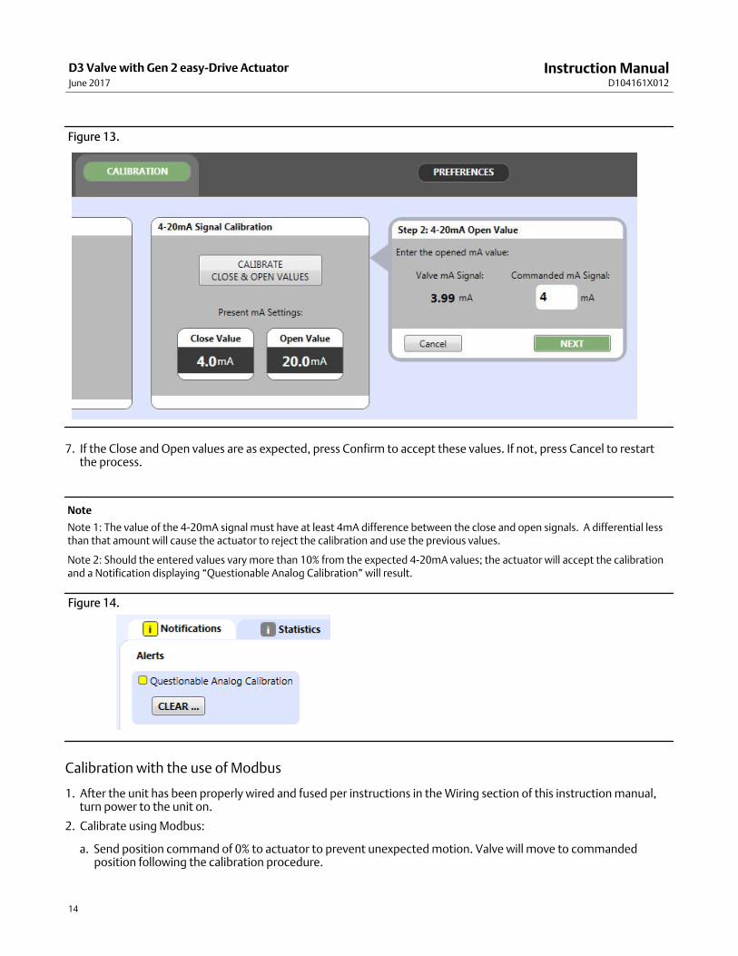
5. Set the 4-20mA signal to the desired value for when the valve is to be open.
6. Enter this value into the Calibrated mA Signal text box and press Next
Instruction ManualD104161X012
D3 Valve with Gen 2 easy-Drive ActuatorJune 2017
14
Figure 13.
7. If the Close and Open values are as expected, press Confirm to accept these values. If not, press Cancel to restartthe process.
Note
Note 1: The value of the 4-20mA signal must have at least 4mA difference between the close and open signals. A differential lessthan that amount will cause the actuator to reject the calibration and use the previous values.
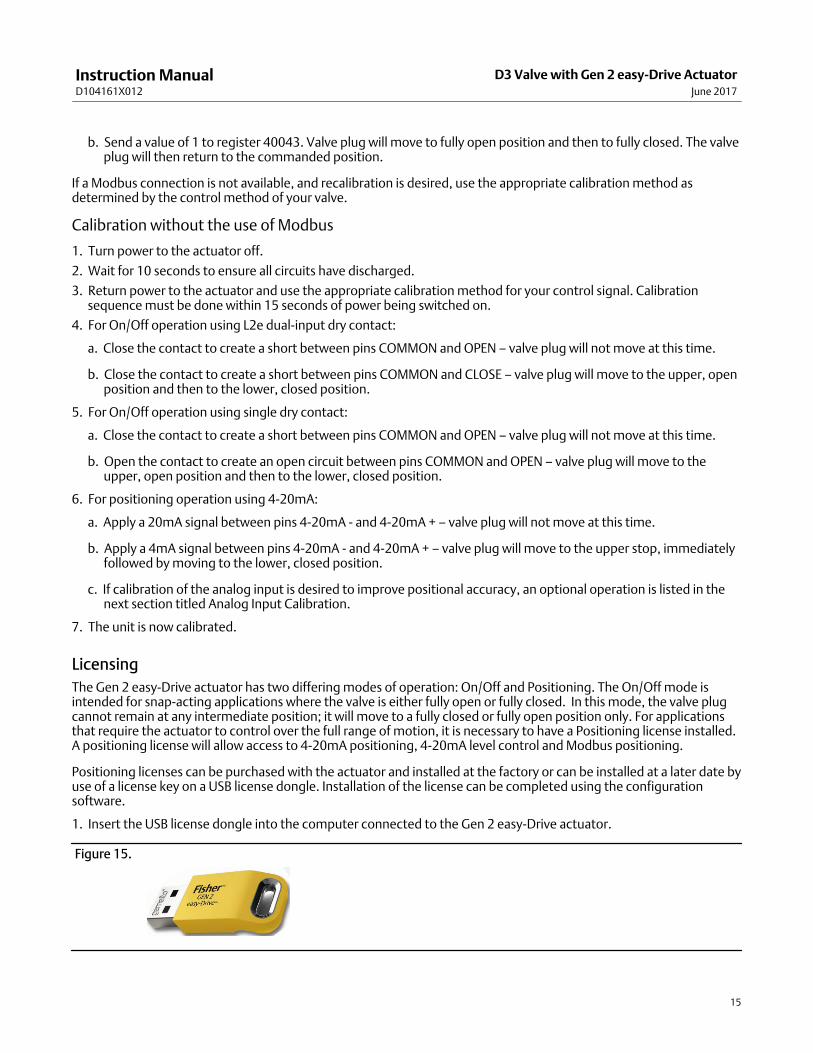
Note 2: Should the entered values vary more than 10% from the expected 4-20mA values; the actuator will accept the calibrationand a Notification displaying “Questionable Analog Calibration” will result.
Figure 14.
Calibration with the use of Modbus
1. After the unit has been properly wired and fused per instructions in the Wiring section of this instruction manual,turn power to the unit on.
2. Calibrate using Modbus:
a. Send position command of 0% to actuator to prevent unexpected motion. Valve will move to commandedposition following the calibration procedure.
Instruction ManualD104161X012
D3 Valve with Gen 2 easy-Drive ActuatorJune 2017
15
b. Send a value of 1 to register 40043. Valve plug will move to fully open position and then to fully closed. The valveplug will then return to the commanded position.
If a Modbus connection is not available, and recalibration is desired, use the appropriate calibration method asdetermined by the control method of your valve.
Calibration without the use of Modbus
1. Turn power to the actuator off.
2. Wait for 10 seconds to ensure all circuits have discharged.
3. Return power to the actuator and use the appropriate calibration method for your control signal. Calibrationsequence must be done within 15 seconds of power being switched on.
4. For On/Off operation using L2e dualinput dry contact:
a. Close the contact to create a short between pins COMMON and OPEN – valve plug will not move at this time.
b. Close the contact to create a short between pins COMMON and CLOSE – valve plug will move to the upper, openposition and then to the lower, closed position.
5. For On/Off operation using single dry contact:
a. Close the contact to create a short between pins COMMON and OPEN – valve plug will not move at this time.
b. Open the contact to create an open circuit between pins COMMON and OPEN – valve plug will move to theupper, open position and then to the lower, closed position.
6. For positioning operation using 420mA:
a. Apply a 20mA signal between pins 4-20mA - and 4-20mA + – valve plug will not move at this time.
b. Apply a 4mA signal between pins 4-20mA - and 4-20mA + – valve plug will move to the upper stop, immediatelyfollowed by moving to the lower, closed position.
c. If calibration of the analog input is desired to improve positional accuracy, an optional operation is listed in thenext section titled Analog Input Calibration.
7. The unit is now calibrated.
Licensing
The Gen 2 easy-Drive actuator has two differing modes of operation: On/Off and Positioning. The On/Off mode isintended for snap-acting applications where the valve is either fully open or fully closed. In this mode, the valve plugcannot remain at any intermediate position; it will move to a fully closed or fully open position only. For applicationsthat require the actuator to control over the full range of motion, it is necessary to have a Positioning license installed.A positioning license will allow access to 4-20mA positioning, 4-20mA level control and Modbus positioning.
Positioning licenses can be purchased with the actuator and installed at the factory or can be installed at a later date byuse of a license key on a USB license dongle. Installation of the license can be completed using the configurationsoftware.
1. Insert the USB license dongle into the computer connected to the Gen 2 easy-Drive actuator.
Figure 15.

Instruction ManualD104161X012
D3 Valve with Gen 2 easy-Drive ActuatorJune 2017
16
2. Click the button labelled MANAGE LICENSES on the left side of the configuration software screen.
Figure 16.
3. The license control screen will open, showing all licenses installed on the USB and the actuator.
Figure 17.
4. After verifying the presence of the desired license on the USB license dongle, click the button labelled ‘easy-Drive’under Move To, and the license will be transferred to the valve as shown below

Instruction ManualD104161X012
D3 Valve with Gen 2 easy-Drive ActuatorJune 2017
17
Figure 18.
5. It is also possible to transfer licenses from one USB license dongle to another. Place two dongles into the computerwith the configuration software. Type in the number of licenses to move and click USB 2 to move the licenses.
Start Up
WARNING
To avoid personal injury or property damage, be aware that the valve will move and respond to an input signal during startup.
1. Before turning on power to the unit, be sure that a closed signal is being commanded to the unit.
� DryContact: contact is open.
� L2e (Dual Dry Contact): Contact closed across pins COMMON and CLOSE.
� Analog Input: signal = 4mA.
� Modbus: position demand = 0.
2. Turn on power to the unit.
3. Apply a change in position demand to ensure unit responds properly.
� DryContact:
� Closed contact between pins COMMON and OPEN will open the valve.
� Dual contact / L2e only: Closed contact between pins COMMON and OPEN will open the valve. Closed contactbetween pins COMMON and CLOSE will close the valve.
� Analog Input: valve will respond to proportional demand.
� Modbus: valve will respond to positional demand in register 40001. 0 = fully closed and 1000 = fully open.

Instruction ManualD104161X012
D3 Valve with Gen 2 easy-Drive ActuatorJune 2017
18
4. If the valve does not respond as expected, proceed to Troubleshooting guide on page 18.
5. Check conduit ports.
� Conduit seal must be in place within 450mm (18 inches) of the enclosure.
� Unused conduit ports must be sealed with an explosionproof port plug.
6. Replace the cover and tighten all 8 bolts to 20 Nm (15 ftlbs).
Troubleshooting1. Unit does not move.
a. Verify that 12VDC to 24VDC is present on the power terminals as shown on the cover. Green heartbeat LED willpulse near Modbus terminals when power is present.
b. Verify that all wires are firmly attached on both ends.
c. Verify that wires are connected to the correct terminals - see Wiring in the manual.
d. Verify mode of operation (on/off or positioning) matches control signal.
e. Verify mode of control (local or Modbus) matches control signal.
2. Unit does not respond to 420mA signal
a. Verify that 12VDC to 24VDC is present on the power terminals as shown on the cover.
b. Verify that the 420mA signal is wired correctly and that the terminals are firmly on the wires.
c. Verify mode of operation matches control signal (local control: 40067=0, positioning: 40065=1).
d. Check the value of the analog input in register 40026 to determine if it is 0 or greater.
i. If register 40026 shows 0, the 4-20mA may be wired backwards. Swap wire and attempt again.
3. Diagnostics show a Motor Stall Fault.
a. The easyDrive electric actuator is designed to operate in a manner consistent with a pneumatic actuator. Thismeans that if the valve plug can not move to its commanded position, the actuator will stop, without damage,and issue a Motor Stall Fault warning. When the command signal changes outside of the deadband (Modbusregister 40036), it will attempt to move again. Recalibrate the actuator span per instructions in the Startupsection of this manual.
4. Position on D3 is not accurate (proportional positioning units only).
a. If the position of a D3 is too high (i.e. 50% is much higher than 50% on the bonnet), check the valve type. If valvetype is D4, change to D3, cycle power, and recalibrate.
b. If the local analog input is being used (420mA or 15V), the analog inputs of the actuator may be calibrated tomatch the input signal.
i. Command 0% (4mA or 1V).
ii. Using a Modbus link, send a 1 to register 40004 or use the Fisher easyDrive configuration software by clickingthe button “Analog Cal at 0%”.
Instruction ManualD104161X012
D3 Valve with Gen 2 easy-Drive ActuatorJune 2017
19
iii. Command 100% (20mA or 5V).
iv. Using a Modbus link, send a 1 to register 40005 or use the Fisher easyDrive configuration software by clickingthe button “Analog Cal at 100%”.
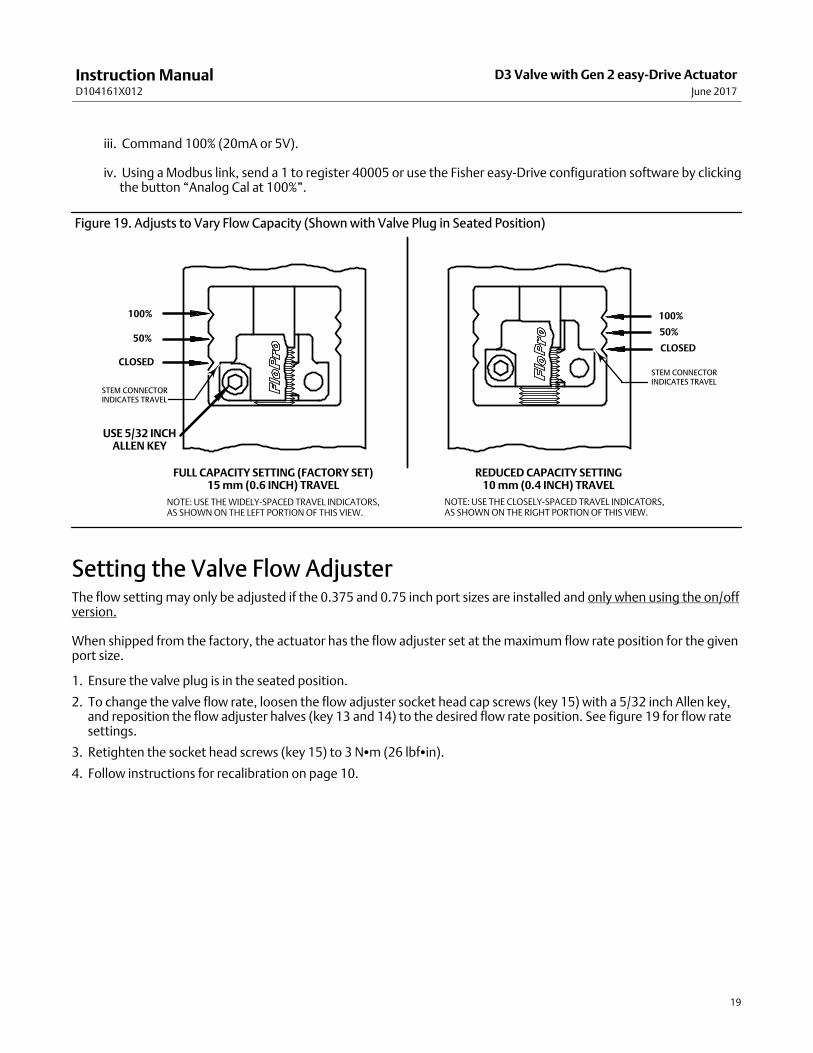
Figure 19. Adjusts to Vary Flow Capacity (Shown with Valve Plug in Seated Position)
CLOSED
50%
100%
CLOSED
50%
100%
USE 5/32 INCHALLEN KEY
FULL CAPACITY SETTING (FACTORY SET)15 mm (0.6 INCH) TRAVEL
NOTE: USE THE WIDELY-SPACED TRAVEL INDICATORS,AS SHOWN ON THE LEFT PORTION OF THIS VIEW.
REDUCED CAPACITY SETTING10 mm (0.4 INCH) TRAVEL
NOTE: USE THE CLOSELY-SPACED TRAVEL INDICATORS,AS SHOWN ON THE RIGHT PORTION OF THIS VIEW.
STEM CONNECTORINDICATES TRAVEL
STEM CONNECTORINDICATES TRAVEL
Setting the Valve Flow AdjusterThe flow setting may only be adjusted if the 0.375 and 0.75 inch port sizes are installed and only when using the on/offversion.
When shipped from the factory, the actuator has the flow adjuster set at the maximum flow rate position for the givenport size.
1. Ensure the valve plug is in the seated position.
2. To change the valve flow rate, loosen the flow adjuster socket head cap screws (key 15) with a 5/32 inch Allen key,and reposition the flow adjuster halves (key 13 and 14) to the desired flow rate position. See figure 19 for flow ratesettings.
3. Retighten the socket head screws (key 15) to 3 N�m (26 lbf�in).
4. Follow instructions for recalibration on page 10.
Instruction ManualD104161X012
D3 Valve with Gen 2 easy-Drive ActuatorJune 2017
20
MaintenanceRefer to figure 22.
Valve parts are subject to normal wear and must be inspected and replaced as necessary. The frequency of inspectionand maintenance depends on the severity of the service conditions.
WARNING
Avoid personal injury from sudden release of process pressure or bursting of parts. Before performing any maintenanceoperations:
� Do not remove the actuator from the valve while the valve is still pressurized.
� Always wear protective gloves, clothing, and eyewear when performing any maintenance operations to avoid personalinjury.
� Disconnect any operating lines providing electric power, or a control signal to the actuator. Be sure the actuator cannotsuddenly open or close the valve.
� Use bypass valves or completely shut off the process to isolate the valve from process pressure. Relieve process pressureon both sides of the valve. Drain the process media from both sides of the valve.
� Use lock‐out procedures to be sure that the above measures stay in effect while you work on the equipment.
� The valve packing box may contain process fluids that are pressurized, even when the valve has been removed from thepipeline. Process fluids may spray out under pressure when removing the packing hardware or packing rings.
� Check with your process or safety engineer for any additional measures that must be taken to protect against processmedia.
WARNING
For explosionproof applications, ensure the actuator cover is properly bolted before applying power to the actuator.Personal injury or property damage may result from fire or explosion if power is applied to the actuator with the coverremoved in a hazardous area.
Do not remove the actuator cover for 10 minutes after power is disconnected if the UPS option is installed.
For explosion‐proof applications, install rigid metal conduit and a conduit seal no more than 457 mm (18 inches) from thetransducer. Personal injury or property damage may result from explosion if the seal is not installed.
Select wiring and/or cable glands that are rated for the environment of use (such as hazardous area, ingress protection, andtemperature). Failure to use properly rated wiring and/or cable glands can result in personal injury or property damagefrom fire or explosion.
Wiring connections must be in accordance with local, regional, and national codes for any given hazardous area approval.Failure to follow the local, regional, and national codes could result in personal injury or property damage from fire orexplosion.

Instruction ManualD104161X012
D3 Valve with Gen 2 easy-Drive ActuatorJune 2017
21
Figure 20. Packing and Belleville Spring Stacking Order
7
10
10
12
8
12
16
43
3
11
LUBRICATE WITH 3mm (1/8 INCH BEAD) OF SUPPLIED HIGH PERFORMANCE FLUORINATED GREASE (KEY 44)
LUBRICATE WITH 3mm (1/8INCH BEAD) OF SUPPLIED HIGHPERFORMANCE FLUORINATEDGREASE
FEMALE PACKING ADAPTOR
MALE PACKING ADAPTOR
PACKING RING
LUBRICATION LOCATIONS ON PACKING
9

Instruction ManualD104161X012
D3 Valve with Gen 2 easy-Drive ActuatorJune 2017
22
Figure 21. Packing and Belleville Spring Stacking Order
VALVE PLUG, BELLEVILLE SPRINGS, AND PACKING RETAINER CORRECTLYINSTALLED AND TIGHTENED
BELLEVILLE SPRINGS FULLY ENCLOSED BYTHE PACKING RETAINER
PACKING RETAINER(KEY 8)
UNTIGHTENED,NOTE THE GAP
FULLY TIGHTENED,NO GAP
Valve Plug and Seat Ring MaintenanceTrim DisassemblyKey numbers are referenced in figures 20, 22, and 23.
1. Isolate the control valve from the line pressure, release pressure from both sides of the valve body (key 1), and drainthe process media from both sides of the valve.
CAUTION
The following steps are intended to prevent damage to the valve plug (key 3) and seat ring (key 2) during the removal of thebonnet and actuator.
For ON/OFF Actuators
2. Command the valve open.
3. Place an open end wrench or a similar obstruction about 6 mm (1/4 inch) thick under the FloPro.
4. Command the valve closed.
For Positioning Actuators
5. Command the valve to anywhere between 10% and 20% travel.
6. Isolate power and signal.

Instruction ManualD104161X012
D3 Valve with Gen 2 easy-Drive ActuatorJune 2017
23
7. Break the bonnet nut (key 5) loose with a hammer. Continue turning the bonnet nut by using a hammer or a largeadjustable wrench, tightened around one ear of the bonnet nut. If the bonnet (key 7) is stuck in the valve, continueto unscrew the bonnet nut. The bonnet nut will contact the spring pins (or pipe plugs) (key 6, figure 22) and jack thebonnet out of the valve. Carefully lift the actuator assembly from the valve body.
WARNING
The spring pins/pipe plugs (key 6) must always be in place during valve operation. They provide a safeguard against injurywhen the unit is being disassembled.
8. Completely remove the packing retainer (key 8) using a 1‐1/8 inch wrench.
9. Remove the valve plug by driving out the pin (key 43) and unscrewing the valve plug from the stem. Do not removethe Belleville springs (key 9) from the stem, in order to retain the Belleville stacking orientation as shown in figure20.
10. Use a 1‐3/16 inch socket wrench to loosen and remove the seat ring (key 2).
CAUTION
Inspect the seat ring and valve body interior for wear, erosion, or damage in the following steps.
11. Inspect the seat ring for wear or damage. If the seating surface has been damaged, discard the seat ring.
12. Visually inspect the valve body interior below the seat ring for erosion or damage. Replace the valve body ifnecessary.
WARNING
Be careful to avoid damaging the seating surface on the valve plug or seat ring as damage in these areas will allow excessiveleakage at shutoff. Avoid damaging the highly polished valve stem surface. A damaged valve stem could cut the packingand allow process fluid to leak to the atmosphere.
Cover the opening in the valve body to prevent foreign material from getting into the valve body cavity.
Trim Assembly1. Ensure the threads of the valve stem (key 16) and valve plug (key 3) are clean and free of debris.
2. Make sure the Belleville springs (key 9) are properly installed on the valve stem, as shown in figure 21.
3. Install the valve plug on the stem and insert a new pin (key 43).
4. Lubricate the threads of the packing retainer with anti‐seize and install into the bonnet using a 1‐1/8 inch wrench.Make sure the Belleville springs (key 9) are completely enclosed by the packing retainer as shown in figure 21.
5. Torque the packing retainer to 81 N�m (60 lbf�ft). The packing retainer has been installed correctly when ametal‐to‐metal contact has been made between the packing retainer end and the bonnet (key 7). The packingretainer threads should be completely enclosed by the bonnet (see figure 21).
6. Thoroughly clean the seat ring (key 2) threads and the mating threads in the valve body (key 1).
7. Apply anti‐seize lubricant to the threads of the seat ring and its mating threads in the valve body.
8. Screw the seat ring into the valve body. Use a 1‐3/16 inch socket wrench to tighten the seat ring to 170 N�m (125lbf�ft). Remove all excess lubricant after tightening.
9. Lubricate the bonnet O‐ring (key 4) with lithium grease and install on the bonnet.

Instruction ManualD104161X012
D3 Valve with Gen 2 easy-Drive ActuatorJune 2017
24
10. Apply anti‐seize lubricant to the threads on the valve body and bonnet nut (key 5) and the contact surfaces of thebonnet and bonnet nut flange. Install the bonnet and actuator assembly onto the valve body. Tighten the bonnetnut until the nut stops turning. A few hammer blows will be required to ensure that the assembly is tight.
Packing Maintenance
WARNING
Observe the warning at the start of the Maintenance section.
Key numbers are referenced in figure 20.
The valve stem packing can only be serviced by removing the bonnet from the valve body.
Packing Disassembly1. Disassemble the valve per steps 1 ‐ 9 in the Trim Disassembly section of the Valve Plug and Seat Ring Maintenance
section of this manual.
2. Remove the five Belleville springs (key 9), lower packing spacer (key 12), packing set (key 11), and twoanti‐extrusion washers (key 10) from the bonnet (key 7) using a formed wire hook.
3. Clean and inspect the packing box wall to ensure that the packing surfaces are not damaged. If the surfacecondition is damaged and cannot be improved by light sanding, replace the bonnet.
4. Inspect the valve stem (key 16) and valve plug (key 3) for scratches or wear and replace if necessary.
Packing AssemblyThe following steps define the proper procedure for installing the packing in a D3 valve. Improper packing assemblycan lead to poor valve performance. The proper packing arrangement is shown in figures 20 and 21.
1. Ensure the upper packing spacer (key 12) is installed.
2. Use the lower packing spacer (key 12) and a tube to push the upper anti‐extrusion washer (key 10) into place. Usingthe lower packing spacer in this manner will ensure the upper anti‐extrusion washer is fully seated and flat wheninstalled in the packing bore.
3. Remove the lower packing spacer from the packing bore.
CAUTION
All D3 packing kits include a single use packet of high performance fluorinated grease. This is the only acceptable D3packing lubricant.
Note
In the following procedure, carefully install each packing ring individually over the valve stem and push completely into the packingbox with a non‐marring tube. A 12‐inch length of 1/2 inch PVC pipe works well for this. It is recommended that the lubricatedpacking rings be installed individually rather than pushed in as a set.
4. Apply a 3mm (1/8 inch) bead of the supplied high performance fluorinated grease (key 44) around the groove ofthe female packing adaptor as shown in figure 20 and install over the valve stem (key 16).
5. Apply a 3mm (1/8 inch) bead of the supplied high performance fluorinated grease (key 44) around the groove ofthe packing ring as shown in figure 20 and install over the valve stem.

Instruction ManualD104161X012
D3 Valve with Gen 2 easy-Drive ActuatorJune 2017
25
6. Install the male packing adaptor, lower anti‐extrusion washer (key 10), and lower packing spacer over the valvestem as shown in figure 20.
7. Firmly press all packing parts into the packing bore with a tube.
8. Install the five Belleville springs (key 9) over the valve stem as shown in figure 20.
9. Install the valve plug (key 3) on the stem and insert a new groove pin (key 43).
10. Lubricate the threads of the packing retainer with anti‐seize and install into the bonnet using a 1‐1/8 inch wrench.Make sure the Belleville springs are completely enclosed by the packing retainer as shown in figure 21.
11. Torque the packing retainer to 81 N�m (60 lbf�ft). The packing retainer has been installed correctly when ametal‐to‐metal contact has been made between the packing retainer end and the bonnet (key 7). The packingretainer threads should be completely enclosed by the bonnet.
12. Apply anti‐seize lubricant to the threads on the valve body and bonnet nut (key 5) and the contact surfaces of thebonnet and bonnet nut flange. Install the bonnet and actuator assembly onto the valve body. Tighten the bonnetnut until the nut stops turning. A few hammer blows will be required to ensure that the assembly is tight.
Stem Replacement
CAUTION
If the valve stem is replaced, the packing will also need to be replaced, since the threads on the valve stem may damage thepacking when the valve stem is removed.
1. Follow the Trim Disassembly procedures, steps 1-8 on page 22 of this manual.
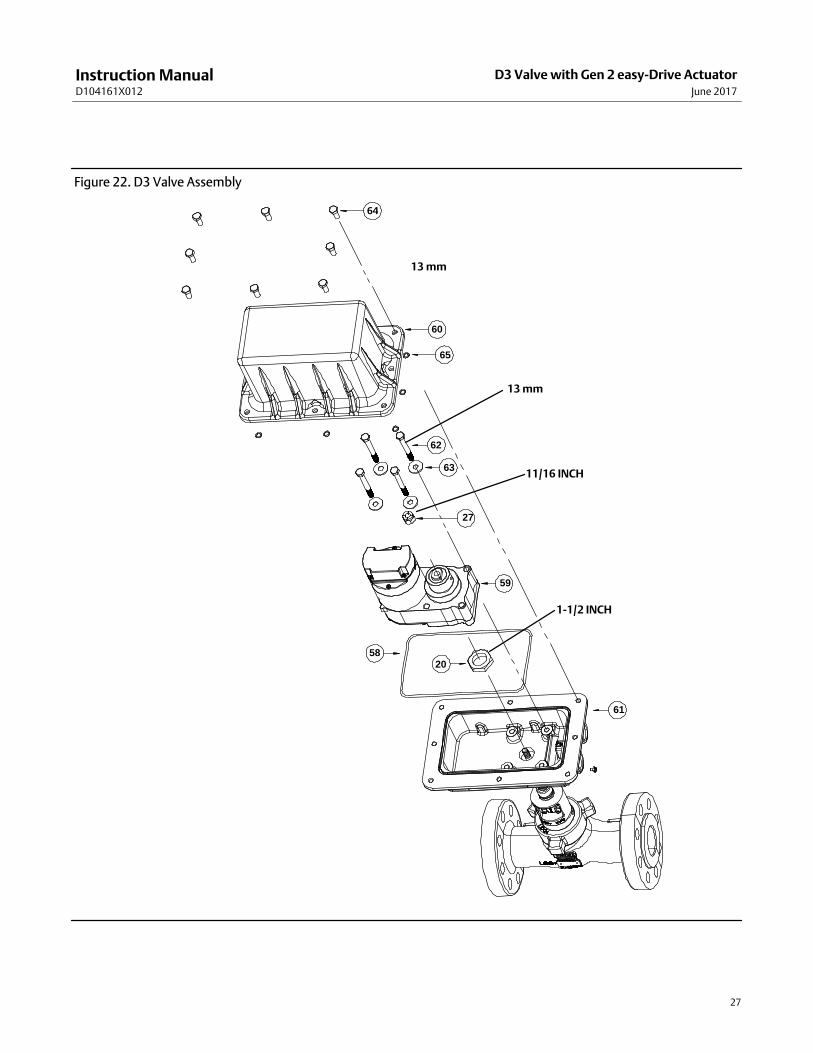
2. Ensure power and signal have been isolated from the actuator. Open the explosion-proof enclosure (keys 60 and61), using a 13mm wrench.
3. Remove the FloPro (keys 13, 14, and 15), using a 5/32 inch hex head wrench.
4. Remove the stem nut (key 27), using an 11/16 inch wrench, noting the position of the FloPro relative to the bonnetmarkings.
5. Use a rubber mallet to gently drive the stem downward through the bottom of the actuator housing and removethe stem.
6. Ensure the packing as been removed, using procedures in the Packing Disassembly on page 24 of this manual.
7. Replace the stem by gently pushing the stem up through the actuator.
8. Replace the packing and plug, using the procedures in the Packing Assembly on page 24 of this manual.
9. Install the FloPro at the same position it was removed from in step 4. Tighten the hex socket head cap screws to 3 N•m (26 lbf•in).
10. Tighten the stem nut (key 27) to 39 N•m (29 lbf•ft) using an 11/16 inch wrench. Be sure the FloPro is not allowedto rotate when tightening the stem nut.
11. Apply anti‐seize lubricant to the threads on the valve body and bonnet nut (key 5) and the contact surfaces of thebonnet and bonnet nut flange. Install the bonnet and actuator assembly onto the valve body. Tighten the bonnetnut until the nut stops turning. A few hammer blows will be required to ensure that the assembly is tight.

Instruction ManualD104161X012
D3 Valve with Gen 2 easy-Drive ActuatorJune 2017
26
Parts OrderingEach D3 control valve is assigned a serial number, which can be found on the nameplate. Refer to the number whencontacting your Emerson sales office or Local Business Partner for assistance or when ordering replacement parts.
WARNING
Use only genuine Fisher replacement parts. Components that are not supplied by Emerson Automation Solutions shouldnot, under any circumstances, be used in any Fisher valve, because they may void your warranty, might adversely affect theperformance of the valve, and could cause personal injury and property damage.
Parts Kits
TRIM KITS
Port Diameter (inches) 0.375 0.75 1
Standard trim kit (Contains keys 2, 3, 4, and 43) RD3STDX0012 RD3STDX0022 RD3STDX0032
Carbide trim kit (Contains keys 2, 3, 4, and 43) RD3CARBX042 RD3CARBX052 RD3CARBX062
PACKING KIT Contains keys 4, 10, 11, 43, and 44 RD3PACKX012
VALVE STEM Key 16 GE48049X012
LICENSE KEY (5 LICENCES) GE83574X022
CONTROLLER BOARDUPGRADE/REPLACEMENT KIT (ON/OFF)
GE83055X012
CONTROLLER BOARDUPGRADE/REPLACEMENT KIT
(POSITIONING)GE83126X012
GEARBOX REPLACEMENT GE84238X012
Parts List
Note
Recommended spare parts are included in the Parts Kits shown at the
top of this page. For additional information or for part numbers not
shown, contact your Emerson sales office or Local Business Partner.
Key Description
1 Valve Body
2* Seat Ring
3* Valve Plug
4* Bonnet O‐ring
5 Bonnet Nut
6 Spring Pin (or alternate pipe plug) (2 req'd)
7 Bonnet
8 Packing Retainer
9 Belleville Springs (5 req'd)
10* Anti‐Extrusion Washer (2 req'd)
11* Packing Set
Key Description
12 Packing Spacer
13 FloPro Half
14 FloPro Half
15 Hex Socket Head Cap Screw (2 req'd)
16* Stem
18* O-ring
20 Locknut
25* Stem O-ring
27 Stem Nut
34 Valve Nameplate
41 Drive Screw (2 req'd)
43* Groove Pin
44* High Performance Fluorinated Grease Packing Lubricant
58 Enclosure O-ring
59 Motor/gearbox/controller assembly
60 Upper Enclosure
61 Lower Enclosure
62 Motor Cap Screws (4 req'd)
63 Motor Cap Screw Washers (4 req'd)
64 Enclosure Cap Screws (8 req'd)
65 Enclosure Cap Screw Retaining Washers (8 req'd)
66 Ground Screw
68 Certification Nameplate
69 easy-Drive Label
*Recommended spare parts
Instruction ManualD104161X012
D3 Valve with Gen 2 easy-Drive ActuatorJune 2017
27
Figure 22. D3 Valve Assembly
64
60
65
62
63
27
59
58
61
20
13 mm
11/16 INCH
1-1/2 INCH
13 mm

Instruction ManualD104161X012
D3 Valve with Gen 2 easy-Drive ActuatorJune 2017
28
Figure 23. D3 Valve Assembly - Cross Sectional View
GE49376-B
APPLY LUBRICANT
Instruction ManualD104161X012
D3 Valve with Gen 2 easy-Drive ActuatorJune 2017
29
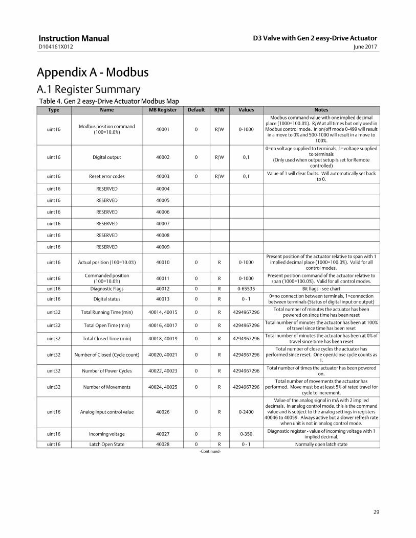
Appendix A - Modbus
A.1 Register SummaryTable 4. Gen 2 easy-Drive Actuator Modbus Map
Type Name MB Register Default R/W Values Notes
uint16Modbus position command
(100=10.0%)40001 0 R/W 0-1000
Modbus command value with one implied decimalplace (1000=100.0%). R/W at all times but only used inModbus control mode. In on/off mode 0-499 will result
in a move to 0% and 500-1000 will result in a move to100%.
uint16 Digital output 40002 0 R/W 0,1
0=no voltage supplied to terminals, 1=voltage suppliedto terminals
(Only used when output setup is set for Remotecontrolled)
uint16 Reset error codes 40003 0 R/W 0,1Value of 1 will clear faults. Will automatically set back
to 0.
uint16 RESERVED 40004
uint16 RESERVED 40005
uint16 RESERVED 40006
uint16 RESERVED 40007
uint16 RESERVED 40008
uint16 RESERVED 40009
uint16 Actual position (100=10.0%) 40010 0 R 0-1000Present position of the actuator relative to span with 1
implied decimal place (1000=100.0%). Valid for allcontrol modes.
uint16Commanded position
(100=10.0%)40011 0 R 0-1000
Present position command of the actuator relative tospan (1000=100.0%). Valid for all control modes.
unit16 Diagnostic Flags 40012 0 R 0-65535 Bit flags - see chart
uint16 Digital status 40013 0 R 0 - 10=no connection between terminals, 1=connectionbetween terminals (Status of digital input or output)
unit32 Total Running Time (min) 40014, 40015 0 R 4294967296Total number of minutes the actuator has been
powered on since time has been reset
uint32 Total Open Time (min) 40016, 40017 0 R 4294967296Total number of minutes the actuator has been at 100%
of travel since time has been reset
uint32 Total Closed Time (min) 40018, 40019 0 R 4294967296Total number of minutes the actuator has been at 0% of
travel since time has been reset
uint32 Number of Closed (Cycle count) 40020, 40021 0 R 4294967296Total number of close cycles the actuator has
performed since reset. One open/close cycle counts as1.
unit32 Number of Power Cycles 40022, 40023 0 R 4294967296Total number of times the actuator has been powered
on.
uint32 Number of Movements 40024, 40025 0 R 4294967296Total number of movements the actuator has
performed. Move must be at least 5% of rated travel forcycle to increment.
unit16 Analog input control value 40026 0 R 0-2400
Value of the analog signal in mA with 2 implieddecimals. In analog control mode, this is the command
value and is subject to the analog settings in registers40046 to 40059. Always active but a slower refresh rate
when unit is not in analog control mode.
uint16 Incoming voltage 40027 0 R 0-350Diagnostic register - value of incoming voltage with 1
implied decimal.
uint16 Latch Open State 40028 0 R 0 - 1 Normally open latch state
-Continued-

Instruction ManualD104161X012
D3 Valve with Gen 2 easy-Drive ActuatorJune 2017
30
Type Name MB Register Default R/W Values Notes
uint16 Latch Close State 40029 0 R 0 - 1 Normally closed latch state
uint16 RESERVED 40030
uint16 RESERVED 40031
uint16 RESERVED 40032
uint16 RESERVED 40033
uint16 RESERVED 40034
uint16 RESERVED 40035
uint16 RESERVED 40036
uint16 RESERVED 40037
uint16 RESERVED 40038
uint16 RESERVED 40039
uint16 Test Register - 16 bit 40040 45964 R 45964Fixed register to test correct reading of 16 bit registers -
Hex=B38C, Binary=1011001110001100
uint32 Test Register - 32 bit 40041, 400423,012,341,
331R 3,012,341,331
Fixed register to test correct reading of 32 bit registers -Hex=B38C AE53, Binary=1011001110001100
1010111001010011
uint16 Span calibration 40043 0 R/W 0,1Value of 1 will initiate span calibration. Will
automatically set back to 0.
uint16 RESERVED 40044
uint16 RESERVED 40045
uint16 RESERVED 40046
uint16 RESERVED 40047
uint16 RESERVED 40048
uint16 RESERVED 40049
uint16Loss of signal position
(100=10.0%)40050 0 R/W 0-1001
Position to which valve plug will be driven upon loss ofsignal. Loss of signal is based upon the active control
mode. 0-1000=0-100.0% with 1 implied decimal point.In on/off mode 0-499 will result in movement to 0%while 500-1000 will result in movement to 100%. Avalue of 1001 in any control mode is the setting for
"lock-in-last".
uint16 Modbus timeout (s) 40051 60 R/W 0-65535
Time without a valid Modbus message is seen (to anyaddress) before "loss of signal" motion is engaged whenin Modbus control mode. Only active in Modbus control
mode. 0=disabled
uint16 Dual contact timeout (s) 40052 60 R/W 0-3600
Time without a digital signal being low (contact made)from either digital input as viewed by voltage level onthe digital input terminals. If neither contact has beenmade (pulled input low) within the timeout period, thevalve plug will be moved to the loss-of-signal position.
Only active in the local, on-off, dual contact mode.0=disabled.
-Continued-
Instruction ManualD104161X012
D3 Valve with Gen 2 easy-Drive ActuatorJune 2017
31
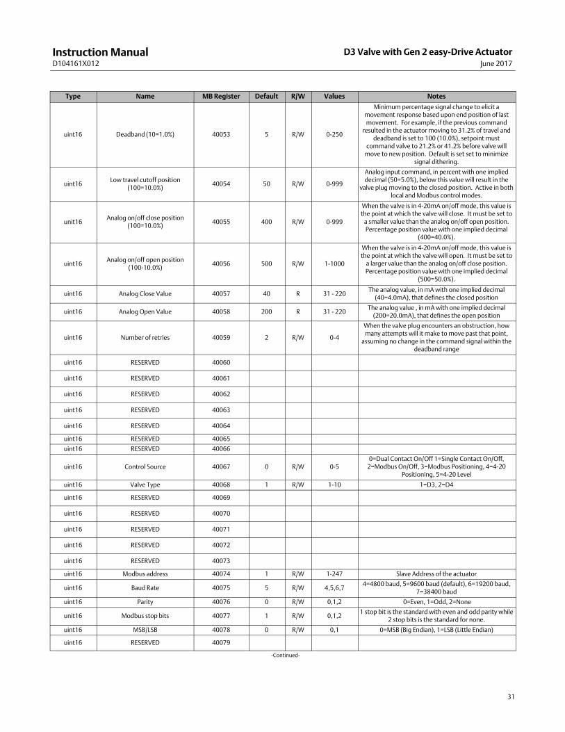
Type Name MB Register Default R/W Values Notes
uint16 Deadband (10=1.0%) 40053 5 R/W 0-250
Minimum percentage signal change to elicit amovement response based upon end position of lastmovement. For example, if the previous command
resulted in the actuator moving to 31.2% of travel anddeadband is set to 100 (10.0%), setpoint must
command valve to 21.2% or 41.2% before valve willmove to new position. Default is set set to minimize
signal dithering.
uint16Low travel cutoff position
(100=10.0%)40054 50 R/W 0-999
Analog input command, in percent with one implieddecimal (50=5.0%), below this value will result in the
valve plug moving to the closed position. Active in bothlocal and Modbus control modes.
unit16Analog on/off close position
(100=10.0%)40055 400 R/W 0-999
When the valve is in 4-20mA on/off mode, this value isthe point at which the valve will close. It must be set to
a smaller value than the analog on/off open position.Percentage position value with one implied decimal
(400=40.0%).
uint16Analog on/off open position
(100-10.0%)40056 500 R/W 1-1000
When the valve is in 4-20mA on/off mode, this value isthe point at which the valve will open. It must be set to
a larger value than the analog on/off close position.Percentage position value with one implied decimal
(500=50.0%).
uint16 Analog Close Value 40057 40 R 31 - 220The analog value, in mA with one implied decimal
(40=4.0mA), that defines the closed position
uint16 Analog Open Value 40058 200 R 31 - 220The analog value , in mA with one implied decimal
(200=20.0mA), that defines the open position
uint16 Number of retries 40059 2 R/W 0-4
When the valve plug encounters an obstruction, howmany attempts will it make to move past that point,
assuming no change in the command signal within thedeadband range
uint16 RESERVED 40060
uint16 RESERVED 40061
uint16 RESERVED 40062
uint16 RESERVED 40063
uint16 RESERVED 40064
uint16 RESERVED 40065
uint16 RESERVED 40066
uint16 Control Source 40067 0 R/W 0-50=Dual Contact On/Off 1=Single Contact On/Off,
2=Modbus On/Off, 3=Modbus Positioning, 4=4-20Positioning, 5=4-20 Level
uint16 Valve Type 40068 1 R/W 1-10 1=D3, 2=D4
uint16 RESERVED 40069
uint16 RESERVED 40070
uint16 RESERVED 40071
uint16 RESERVED 40072
uint16 RESERVED 40073
uint16 Modbus address 40074 1 R/W 1-247 Slave Address of the actuator
uint16 Baud Rate 40075 5 R/W 4,5,6,74=4800 baud, 5=9600 baud (default), 6=19200 baud,
7=38400 baud
uint16 Parity 40076 0 R/W 0,1,2 0=Even, 1=Odd, 2=None
unit16 Modbus stop bits 40077 1 R/W 0,1,21 stop bit is the standard with even and odd parity while
2 stop bits is the standard for none.
uint16 MSB/LSB 40078 0 R/W 0,1 0=MSB (Big Endian), 1=LSB (Little Endian)
uint16 RESERVED 40079
-Continued-
Instruction ManualD104161X012
D3 Valve with Gen 2 easy-Drive ActuatorJune 2017
32
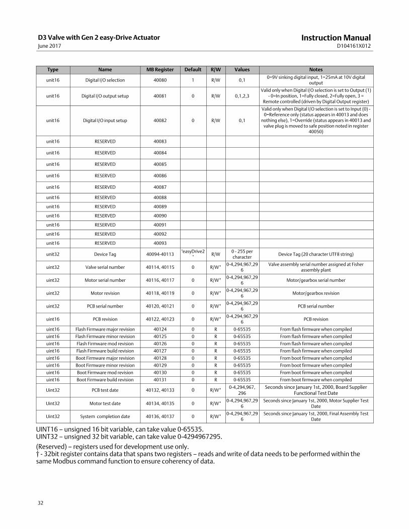
Type Name MB Register Default R/W Values Notes
unit16 Digital I/O selection 40080 1 R/W 0,10=9V sinking digital input, 1=25mA at 10V digital
output
unit16 Digital I/O output setup 40081 0 R/W 0,1,2,3Valid only when Digital I/O selection is set to Output (1)
- 0=In position, 1=Fully closed, 2=Fully open, 3 =Remote controlled (driven by Digital Output register)
unit16 Digital I/O input setup 40082 0 R/W 0,1
Valid only when Digital I/O selection is set to Input (0) -0=Reference only (status appears in 40013 and does
nothing else), 1=Override (status appears in 40013 andvalve plug is moved to safe position noted in register
40050)
unit16 RESERVED 40083
unit16 RESERVED 40084
unit16 RESERVED 40085
unit16 RESERVED 40086
unit16 RESERVED 40087
unit16 RESERVED 40088
unit16 RESERVED 40089
unit16 RESERVED 40090
unit16 RESERVED 40091
unit16 RESERVED 40092
unit16 RESERVED 40093
unit32 Device Tag 40094-40113"easyDrive2
"R/W
0 - 255 percharacter
Device Tag (20 character UTF8 string)
uint32 Valve serial number 40114, 40115 0 R/W*0-4,294,967,29
6Valve assembly serial number assigned at Fisher
assembly plant
uint32 Motor serial number 40116, 40117 0 R/W*0-4,294,967,29
6Motor/gearbox serial number
uint32 Motor revision 40118, 40119 0 R/W*0-4,294,967,29
6Motor/gearbox revision
uint32 PCB serial number 40120, 40121 0 R/W*0-4,294,967,29
6PCB serial number
uint16 PCB revision 40122, 40123 0 R/W*0-4,294,967,29
6PCB revision
uint16 Flash Firmware major revision 40124 0 R 0-65535 From flash firmware when compiled
uint16 Flash Firmware minor revision 40125 0 R 0-65535 From flash firmware when compiled
uint16 Flash Firmware mod revision 40126 0 R 0-65535 From flash firmware when compiled
uint16 Flash Firmware build revision 40127 0 R 0-65535 From flash firmware when compiled
uint16 Boot Firmware major revision 40128 0 R 0-65535 From boot firmware when compiled
uint16 Boot Firmware minor revision 40129 0 R 0-65535 From boot firmware when compiled
uint16 Boot Firmware mod revision 40130 0 R 0-65535 From boot firmware when compiled
uint16 Boot Firmware build revision 40131 0 R 0-65535 From boot firmware when compiled
Uint32 PCB test date 40132, 40133 0 R/W*0-4,294,967,
296
Seconds since January 1st, 2000, Board SupplierFunctional Test Date
Uint32 Motor test date 40134, 40135 0 R/W*0-4,294,967,29
6Seconds since January 1st, 2000, Motor Supplier Test
Date
Uint32 System completion date 40136, 40137 0 R/W*0-4,294,967,29
6Seconds since January 1st, 2000, Final Assembly Test
Date
UINT16 – unsigned 16 bit variable, can take value 0-65535.UINT32 – unsigned 32 bit variable, can take value 0-4294967295.
(Reserved) – registers used for development use only.† - 32bit register contains data that spans two registers – reads and write of data needs to be performed within thesame Modbus command function to ensure coherency of data.

Instruction ManualD104161X012
D3 Valve with Gen 2 easy-Drive ActuatorJune 2017
33
Table 5. Diagnostic Fault FlagsHex Value Bit Mask Description Value Bit Definition
0x8000 1000 0000 0000 0000Fault in N.V. Memory – system has restoreddefault settings
32768 15
A memory fault has occurred and theactuator has been restored to factorydefaults. Contact your Emerson LocalBusiness Partner.
0x8000 1000 0000 0000 0000Fault in N.V. Memory – system has restoreddefault settings
32768 15
A memory fault has occurred and theactuator has been restored to factorydefaults. Contact your Emerson LocalBusiness Partner.
0x4000 0100 0000 0000 0000 Motor Assembly Stall 16384 14
The actuator is unable to move to thecommanded position and has stopped.Follow troubleshooting guide in Help sectionto remedy.
0x2000 0010 0000 0000 0000 Discrete Input override mode active 8192 13
The digital input has detected a closedcontact and the actuator has moved to itssafe position. Check switch input devicestatus.
0x1000 0001 0000 0000 0000 System or Watchdog fault 4096 12The actuator has experienced a fatal error andshut down. Contact your Emerson LocalBusiness Partner.
0x0800 0000 1000 0000 0000Analog Input calibration value not in expectedrange
2048 11The analog values entered do not match theanalog signal level. Check analog signal valueand value entered.
0x0400 0000 0100 0000 0000Valve travel distance calibration not in legalrange
1024 10The valve travel distance is outside theacceptable range. Confirm valve type andthat no obstructions are present.
0x0200 0000 0010 0000 0000Analog Input span calibration not in legalrange
512 9
The analog values for open and close are lessthan 4mA and previous values have beenmaintained. Calibrate analog input withdifferential >4mA.
0x0100 0000 0001 0000 0000 256 8
0x0080 0000 0000 1000 0000 Valve was shutdown while moving 128 7Actuator was powered down during a moveand actual position may vary fromcommanded. Recalibrate the valve span.
0x0040 0000 0000 0100 0000 Valve span calibrated (informational) 64 6Span has been calibrated and actuator isready.
0x0020 0000 0000 0010 0000Valve position controller active(informational)
32 5 Actuator is active and ready.
0x0010 0000 0000 0001 0000 Loss of signal active 16 4Control signal not present. Signal is <3mA,timeout period exceeded (40051 or 40052).
0x0008 0000 0000 0000 1000 8 3
0x0004 0000 0000 0000 0100Modbus command has been sent (starts acalibrated system)
4 2 The actuator is successfully moving the valve.
0x0002 0000 0000 0000 0010Analog input initialized (system has seeninput >3mA/1V)
2 14-20mA analog input has a valid signalpresent
0x0001 0000 0000 0000 0001Start delay active (within 15 secondcalibration window)
1 0Span calibration using physical inputs allowedduring startup

Instruction ManualD104161X012
D3 Valve with Gen 2 easy-Drive ActuatorJune 2017
34
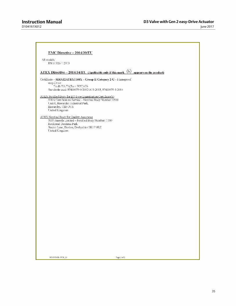
Appendix B - Certificate of Conformance
Instruction ManualD104161X012
D3 Valve with Gen 2 easy-Drive ActuatorJune 2017
35

Instruction ManualD104161X012
D3 Valve with Gen 2 easy-Drive ActuatorJune 2017
36
Emerson Automation Solutions Marshalltown, Iowa 50158 USASorocaba, 18087 BrazilCernay, 68700 FranceDubai, United Arab EmiratesSingapore 128461 Singapore
www.Fisher.com
The contents of this publication are presented for informational purposes only, and while every effort has been made to ensure their accuracy, they are notto be construed as warranties or guarantees, express or implied, regarding the products or services described herein or their use or applicability. All sales aregoverned by our terms and conditions, which are available upon request. We reserve the right to modify or improve the designs or specifications of suchproducts at any time without notice.
� 2016, 2017 Fisher Controls International LLC. All rights reserved.
Fisher and easy-Drive are marks owned by one of the companies in the Emerson Automation Solutions business unit of Emerson Electric Co. EmersonAutomation Solutions, Emerson, and the Emerson logo are trademarks and service marks of Emerson Electric Co. All other marks are the property of theirrespective owners.
Neither Emerson, Emerson Automation Solutions, nor any of their affiliated entities assumes responsibility for the selection, use or maintenanceof any product. Responsibility for proper selection, use, and maintenance of any product remains solely with the purchaser and end user.