d101634x012 august 2018 fisher hp and hpa control valves · this instruction manual includes...
TRANSCRIPT
www.Fisher.com
Fisher™ HP and HPA Control Valves
ContentsIntroduction 1. . . . . . . . . . . . . . . . . . . . . . . . . . . . . . . . .
Scope of Manual 1. . . . . . . . . . . . . . . . . . . . . . . . . . . . .Description 2. . . . . . . . . . . . . . . . . . . . . . . . . . . . . . . . .Specifications 3. . . . . . . . . . . . . . . . . . . . . . . . . . . . . . .Educational Services 5. . . . . . . . . . . . . . . . . . . . . . . . .
Installation 6. . . . . . . . . . . . . . . . . . . . . . . . . . . . . . . . . .Maintenance 7. . . . . . . . . . . . . . . . . . . . . . . . . . . . . . . . .
Packing Lubrication 9. . . . . . . . . . . . . . . . . . . . . . . . . .Packing Maintenance 9. . . . . . . . . . . . . . . . . . . . . . . . .
Adding Packing Rings 12. . . . . . . . . . . . . . . . . . . .Replacing Packing 12. . . . . . . . . . . . . . . . . . . . . . .
Trim Removal 16. . . . . . . . . . . . . . . . . . . . . . . . . . . . . .Constructions other than TSO Trim 17. . . . . . . .TSO Trim 17. . . . . . . . . . . . . . . . . . . . . . . . . . . . . .
Valve Plug Maintenance 18. . . . . . . . . . . . . . . . . . . . .Lapping Seats 19. . . . . . . . . . . . . . . . . . . . . . . . . . . . . .Trim Replacement 23. . . . . . . . . . . . . . . . . . . . . . . . . .
NPS 2 to 6 HPD, HPT and NPS 2 to 8 HPAD, HPAT 24. . . . . . . . . . . . . . . . . . . . . . . . .
NPS 8 to 12 HPD, HPT Constructions 25. . . . . . .Retrofit: Installing C‐seal Trim 28. . . . . . . . . . . . . . . .Replacement of Installed C‐seal Trim 32. . . . . . . . . . .
Trim Removal (C‐seal Constructions) 32. . . . . . .Lapping Metal Seats (C‐seal Constructions) 33. .Remachining Metal Seats
(C‐seal Constructions) 33. . . . . . . . . . . . . . . . .Trim Replacement (C‐seal Constructions) 34. . .
Replacement of Installed Bore Seal Trim 36. . . . . . . .Trim Removal (Bore Seal Constructions) 36. . . .Trim Replacement (Bore Seal Constructions) 36
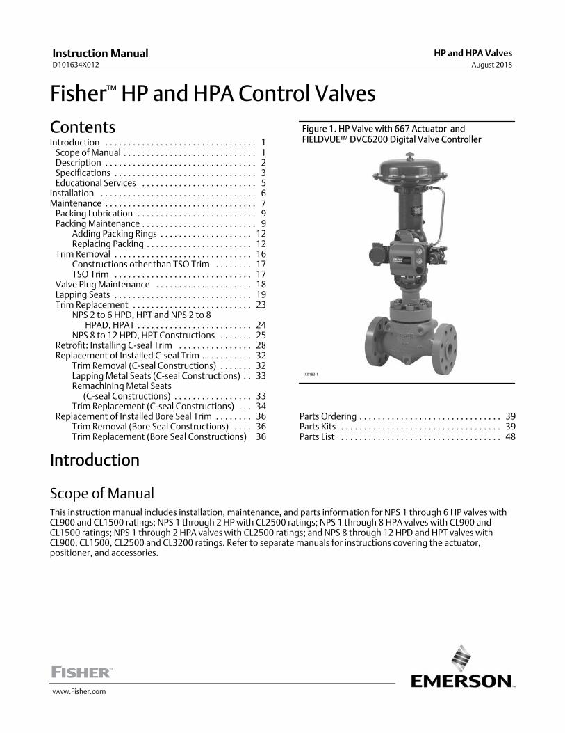
Figure 1. HP Valve with 667 Actuator andFIELDVUE™ DVC6200 Digital Valve Controller
X0183-1
Parts Ordering 39. . . . . . . . . . . . . . . . . . . . . . . . . . . . . . .Parts Kits 39. . . . . . . . . . . . . . . . . . . . . . . . . . . . . . . . . . .Parts List 48. . . . . . . . . . . . . . . . . . . . . . . . . . . . . . . . . . .
Introduction
Scope of ManualThis instruction manual includes installation, maintenance, and parts information for NPS 1 through 6 HP valves withCL900 and CL1500 ratings; NPS 1 through 2 HP with CL2500 ratings; NPS 1 through 8 HPA valves with CL900 andCL1500 ratings; NPS 1 through 2 HPA valves with CL2500 ratings; and NPS 8 through 12 HPD and HPT valves withCL900, CL1500, CL2500 and CL3200 ratings. Refer to separate manuals for instructions covering the actuator,positioner, and accessories.
Instruction ManualD101634X012
HP and HPA ValvesAugust 2018

Instruction ManualD101634X012
HP and HPA ValvesAugust 2018
2
Table 1. Specifications
End Connection Styles and Ratings(1,2,3,4)
Flanged: Consistent with CL900, CL1500, and CL2500per ASME B16.34
Socket Welding: Consistent with CL900, CL1500, andCL2500 per ASME B16.34
Buttwelding: Consistent with CL900, CL1500, CL2500and intermediate rating CL3200 per ASME B16.34
Also see table 2
Shutoff Classifications
See table 3
C‐seal trim: High‐temperature, Class V
Bore seal trim: High‐temperature, Class V
See table 4
TSO (Tight Shutoff) trim: See tables 5 and 6
Flow Characteristic
Standard Cage: � Equal percentage, � Modifiedequal percentage, or � Linear
Standard Cage with Micro‐Form Valve Plug: (HPS andHPAS only): � Equal percentage or � Modified equalpercentage
Standard Cage with Micro‐Flute Valve Plug: (HPS andHPAS only): � Equal percentage or � Modified equalpercentage
Standard Cage with Micro‐Flat Valve Plug: (HPASonly): � Linear
Cavitrol™ III, Whisper Trim™ III, or WhisperFlo™ Cage: � Linear
Special cages: Special characterized flow cages areavailable. Consult your local Emerson sales office orLocal Business Partner
Flow Direction
Standard Cage
� HPD and HPAD: Normally flow down� HPS and HPAS: Normally flow up(5)
� HPAS Micro‐Flat: Flow down� HPT and HPAT: Normally flow down� HPS and HPAS Micro‐Form: Flow up only
Cavitrol III Cage: Flow down
Whisper Trim III or WhisperFlo Cage: Flow up
Approximate Weights (valve body and bonnetassemblies)
See table 2
Additional Specifications
For specifications such as materials, valve plugtravels, and port, yoke boss, and stem diameters, seethe Parts List section
1. EN (or other) ratings and end connections can usually be supplied; consult your Emerson sales office.2. CL900 and CL1500 globe valves are identical for NPS 1 and 2 valves. CL900 and CL1500 globe valves for NPS 3, 4, 6, 8, 10, and 12 valves, however, are not identical.3. The centerline‐to‐face dimension for CL2500 NPS 1 and 2 HPA valves does not conform to ANSI/ISA S75.12.4. The pressure or temperature limits in this manual and any applicable standard limitations should not be exceeded.5. HPS and HPAS valves may be used flow down for on‐off service only or where further limited by trim design. HPAS valves may be used flow down for erosive service.
Do not install, operate, or maintain HP series valves without being fully trained and qualified in valve, actuator, andaccessory installation, operation, and maintenance. To avoid personal injury or property damage, it is important tocarefully read, understand, and follow all the contents of this manual, including all safety cautions and warnings. If youhave any questions about these instructions, contact your Emerson sales office or Local Business Partner beforeproceeding.
Unless otherwise noted, all NACE references are to NACE MR0175‐2002 and MR0103.
DescriptionHP Series high‐pressure globe and angle valves (figure 1) have metal seats, cage guiding, quick change trim, andpush‐down‐to‐close valve plug action. HPD, HPAD, HPT, and HPAT valves use balanced valve plugs. HPS and HPASvalves use an unbalanced valve plug. To provide a seal between the cage and a balanced valve plug, the HPD and HPADvalve plugs use piston rings; the HPT and HPAT valve plugs use a pressure‐assisted seal ring. A Whisper Trim orWhisperFlo cage can be used with an HPD, HPAD, HPS, HPAS, HPT, or HPAT valve plug. A Cavitrol III cage can be usedwith an HPS, HPAS, HPT, or HPAT valve plug.
Instruction ManualD101634X012
HP and HPA ValvesAugust 2018
3
C‐seal trim is available for HPD valves, CL900 and CL1500 in sizes NPS 3, 4 and 6; and for HPAD valves, CL900 andCL1500 in sizes NPS 4, 6, and 8. Bore seal trim is available for HPD valves, CL900, CL1500, CL2500 and CL3200 in sizesNPS 8, 10 and 12.
With C‐seal trim and bore seal trim, a balanced valve can achieve high‐temperature, Class V shutoff. Because the seal isformed from metal (N07718 nickel alloy) rather than an elastomer, a valve equipped with the C‐seal trim or bore sealtrim can be applied in processes with a fluid temperature of up to 593�C (1100�F), provided other material limits arenot exceeded.
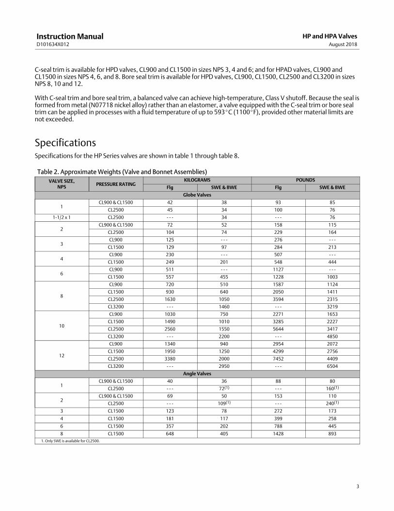
SpecificationsSpecifications for the HP Series valves are shown in table 1 through table 8.
Table 2. Approximate Weights (Valve and Bonnet Assemblies)
VALVE SIZE,NPS
PRESSURE RATINGKILOGRAMS POUNDS
Flg SWE & BWE Flg SWE & BWE
Globe Valves
1CL900 & CL1500 42 38 93 85
CL2500 45 34 100 76
1‐1/2 x 1 CL2500 ‐ ‐ ‐ 34 ‐ ‐ ‐ 76
2CL900 & CL1500 72 52 158 115
CL2500 104 74 229 164
3CL900 125 ‐ ‐ ‐ 276 ‐ ‐ ‐
CL1500 129 97 284 213
4CL900 230 ‐ ‐ ‐ 507 ‐ ‐ ‐
CL1500 249 201 548 444
6CL900 511 ‐ ‐ ‐ 1127 ‐ ‐ ‐
CL1500 557 455 1228 1003
8
CL900 720 510 1587 1124
CL1500 930 640 2050 1411
CL2500 1630 1050 3594 2315
CL3200 - - - 1460 - - - 3219
10
CL900 1030 750 2271 1653
CL1500 1490 1010 3285 2227
CL2500 2560 1550 5644 3417
CL3200 - - - 2200 - - - 4850
12
CL900 1340 940 2954 2072
CL1500 1950 1250 4299 2756
CL2500 3380 2000 7452 4409
CL3200 - - - 2950 - - - 6504
Angle Valves
1CL900 & CL1500 40 36 88 80
CL2500 ‐ ‐ ‐ 72(1) ‐ ‐ ‐ 160(1)
2CL900 & CL1500 69 50 153 110
CL2500 ‐ ‐ ‐ 109(1) ‐ ‐ ‐ 240(1)
3 CL1500 123 78 272 173
4 CL1500 181 117 399 258
6 CL1500 357 202 788 445
8 CL1500 648 405 1428 893
1. Only SWE is available for CL2500.

Instruction ManualD101634X012
HP and HPA ValvesAugust 2018
4
Table 3. Shutoff Classifications per ANSI/FCI 70‐2 and IEC 60534‐4VALVE DESIGN PORT DIAMETER, mm (INCHES) LEAKAGE CLASS
HPD, HPAD
47.6 (1.875) and smaller II
58.7 (2.3125) to 92.1 (3.625)II ‐ Standard
III ‐ Optional
111.1 (4.375) to 203.2 (8.0)III ‐ Standard
IV ‐ Optional
HPD w/Bore Seal Trim139.7 (5.5) to 203.2 (8.0)
IV-Standard
V-Standard
HPS, HPAS w/ Cavitrol III, orHPT, HPAT w/ Cavitrol III, or HPAS w/Micro‐Flat
All V
HPS, HPAS, HPT, HPAT, HPS, HPAS w/ Micro‐Form,or HPS, HPAS w/ Micro‐Flute All
IV‐Standard
V‐Optional
HPT w/ PEEK anti‐extrusion rings 47.6 (1.875) to 203.2 (8.0) V ‐ Standard
Table 4. Additional Shutoff Classification per ANSI/FCI 70‐2 and IEC 60534‐4
Valve DesignValve Size, NPS Port Diameter
Cage Style Leakage ClassHPD HPAD mm Inches
HPD, HPADwith optional
C‐seal trim
3 4 73.0 2.875
Equal Percentage, Modified Equal Percentage,Linear (std. cage),
Linear (Whisper III, A1, B1)V
4 6 73.0 2.875 Linear (Whisper III, D3) V
4 6 92.1 3.625
Equal Percentage, Modified Equal Percentage,Linear (std. cage),
Linear (Whisper III, A1, B3, C3)V
6 8 111.1 4.375 Linear (Whisper III, D3) V
6 8 136.5 5.375
Equal Percentage, Modified Equal Percentage,Linear (std. cage),
Linear (Whisper III, A1, B3, C3)V
HPD withoptional
Bore-seal trim
Valve Size, NPS Port DiameterCage Style Leakage Class
HPD HPT mm Inches
8 - - -139.7 5.5
Eq. %, Linear (std. cage), Whisper III, Cavitrol III
V - Standardto 593°C (1100°F)(for port diameters
from 139.7 mm[5.5 inch] through203.2 mm [8 inch]
with optionalBore-seal trim)
152.4 6
10 - - -165.1 6.5
177.8 7
12 - - -190.5 7.5
203.2 8
Table 5. TSO (Tight Shutoff) Leakage Class per ANSI/FCI 70‐2 and IEC 60534‐4(1)
Leakage Class Maximum Leakage Test Medium Test Pressure Leakage Class
TSO (Tight Shutoff)Valves with TSO trim are factory tested to a morestringent Emerson test requirement of no leakage
at time of shipment.
Water Service ⊗P(2) V
1. Not available for NPS 8 to 12 HPD and HPT.2. Specify service ⊗P when ordering.
Table 6. TSO Shutoff Availability(1)
VALVE DESIGN CONSTRUCTION LEAKAGE CLASS
HPS, HPT Std or Cavitrol III trim. Replaceable, protected soft seat TSO - Standard
1. Not available for NPS 8 to 12 HPD and HPT.

Instruction ManualD101634X012
HP and HPA ValvesAugust 2018
5
Table 7. Recommended Torque for Packing Flange Nuts (Non Live‐loaded Graphite Packing)
STEMDIAMETER VALVE BODY
RATING(1)
TORQUE
N�m lbf�ft
mm Inches Min Max Min Max
12.7 1/2 CL900 12 18 9 13
12.7 1/2 CL1500 15 22 11 16
12.7 1/2 CL2500 18 24 13 18
19.1 3/4 CL900 27 41 20 30
19.1 3/4 CL1500 34 50 25 37
19.1 3/4 CL2500 41 61 30 45
25.4 1 CL900 42 62 31 46
25.4 1 CL1500 52 77 38 57
25.4 1 CL2500 61 91 45 67
31.8 1‐1/4 CL900 56 83 41 61
31.8 1‐1/4 CL1500 68 102 50 75
31.8 1‐1/4 CL2500 81 122 60 90
31.8 1‐1/4 CL3200 81 122 60 90
50.8 2 CL1500 98 146 72 108
50.8 2 CL2500 115 170 85 125
50.8 2 CL3200 115 170 85 125
1. For intermediate class ratings, use the same torque as the next lower standard class.
Table 8. Torque for Body‐to‐Bonnet Bolting Using Anti‐Seize Lubricant(1)
VALVE RATING VALVE SIZE, NPSTORQUE
N•m lbf•ft
HP HPA B7, B16, B8M CL2, BD, S20910, and 660 Studs B7, B16, B8M CL2, BD, S20910, and 660 Studs
CL900 & CL1500
1 1 260 190
2 2, 3 370 275
3 4 710 525
4 6 940 695
6 8 1650 1220
8 8 2240 1650
10 10 2810 2070
12 12 2810 2070
CL2500
1 1 370 275
2 2 710 525
8 8 8410 6200
10 10 6090 4490
12 12 6090 4490
CL3200 8,10,12 8,10,12 8410 6200
1. For other materials, contact your Emerson sales office or Local Business Partner for torques.
Educational ServicesFor information on available courses for Fisher HP and HPA valves, as well as a variety of other products, contact:
Emerson Automation SolutionsEducational Services - RegistrationPhone: 1-641-754-3771 or 1-800-338-8158E-mail: [email protected]/fishervalvetraining

Instruction ManualD101634X012
HP and HPA ValvesAugust 2018
6
Installation
WARNING
Always wear protective gloves, clothing, and eyewear when performing any installation operations to avoid personalinjury.
Personal injury or equipment damage caused by sudden release of pressure may result if the valve assembly is installedwhere service conditions could exceed the limits given in table 1 or on the appropriate nameplates. To avoid such injury ordamage, provide a relief valve for over‐pressure protection as required by government or accepted industry codes andgood engineering practices.
Check with your process or safety engineer for any additional measures that must be taken to protect against processmedia.
If installing into an existing application, also refer to the WARNING at the beginning of the Maintenance section in thisinstruction manual.
WARNING
Some bonnet flanges have a tapped hole that was used to handle the bonnet during manufacture. Do not use this tappedhole to lift the valve assembly or personal injury may result.
WARNING
When ordered, the valve configuration and construction materials were selected to meet particular pressure, temperature,pressure drop, and controlled fluid conditions indicated when the valve was ordered. Since some body/trim materialcombinations are limited in their pressure drop and temperature ranges, do not apply any other conditions to the valvewithout first contacting your Emerson sales office or Local Business Partner.
1. Before installing the valve, inspect it to ensure that the valve body cavity is free of foreign material.
2. Clean out all pipelines to remove scale, welding slag, and other foreign materials before installing the valve.
Note
If the valve body being installed has small internal flow passages, such as with Whisper Trim III, WhisperFlo, or Cavitrol III cages,consideration should be given to installing an upstream strainer to prevent the lodging of particles in these passages. This isespecially important if the pipeline cannot be thoroughly cleaned or if the flowing medium is not clean.
3. Flow through the valve must be in the direction indicated by the flow arrow, which is stamped on or attached to thevalve body.
Note
NPS 8 to 12 CL900, CL1500, CL2500 and CL3200 HPD and HPT valves contain a flow vane in the lower flow passage. This is criticalto the proper function of the valve, and is not a defect.

Instruction ManualD101634X012
HP and HPA ValvesAugust 2018
7
CAUTION
Depending on valve body materials used, post‐weld heat treating might be needed. Post‐weld heat treatment can damageinternal elastomeric, plastic, and metal parts. Shrink‐fit pieces and threaded connections might also loosen. In general, ifpost‐weld heat treating is needed, remove all trim parts. Contact your Emerson sales office or Local Business Partner foradditional information.
4. Use accepted piping and welding practices when installing the valve in the pipeline. For flanged valve bodies, use asuitable gasket between the body and pipeline flanges.
5. Install a three‐valve bypass around the valve if continuous operation is required during maintenance.
6. If the actuator and valve body are shipped separately, refer to the actuator mounting procedure in the appropriateactuator instruction manual.
7. If the valve body was shipped without packing installed in the packing box, install the packing before putting thevalve body into service. Refer to instructions given in the Packing Maintenance procedure.
WARNING
Personal injury could result from packing leakage. Valve packing was tightened before shipment; however, the packingmight require some readjustment to meet specific service conditions.
Valves with ENVIRO‐SEAL™ live‐loaded packing or HIGH‐SEAL ULF live‐loaded packing will not require this initialre‐adjustment. See the instruction manuals titled ENVIRO‐SEAL Packing System for Sliding‐Stem Valves(D101642X012) or HIGH‐SEAL ULF Live‐Loaded Packing System (D101453X012) (as appropriate) for packinginstructions. If you wish to convert your present packing arrangement to ENVIRO‐SEAL packing, refer to the retrofitkits listed in the parts kit sub‐section near the end of this manual.
MaintenanceValve parts are subject to normal wear and must be inspected and replaced as necessary. Inspection and maintenancefrequency depends on the severity of service conditions. This section includes instructions for packing lubrication,packing maintenance, and trim maintenance. All maintenance operations may be performed with the valve in the line.
WARNING
Avoid personal injury or damage to property from sudden release of pressure or uncontrolled process fluid. Before startingdisassembly:
� Do not remove the actuator from the valve while the valve is still pressurized.
� Always wear protective gloves, clothing, and eyewear when performing any maintenance operations to avoid personalinjury.
� Disconnect any operating lines providing air pressure, electric power, or a control signal to the actuator. Be sure theactuator cannot suddenly open or close the valve.
� Use bypass valves or completely shut off the process to isolate the valve from process pressure. Relieve process pressureon both sides of the valve. Drain the process media from both sides of the valve.
� Vent the power actuator loading pressure and relieve any actuator spring precompression.
� Use lock‐out procedures to be sure that the above measures stay in effect while you work on the equipment.
Instruction ManualD101634X012
HP and HPA ValvesAugust 2018
8
� The valve packing box may contain process fluids that are pressurized, even when the valve has been removed from thepipeline. Process fluids may spray out under pressure when removing the packing hardware or packing rings, or whenloosening the packing box pipe plug.
� Check with your process or safety engineer for any additional measures that must be taken to protect against processmedia.
Note
The HP series valve uses spiral‐wound gaskets which are crushed to provide their seal. A spiral‐wound gasket should never bereused. Whenever a gasket seal is disturbed by removing or shifting gasketed parts, a new gasket must be installed uponreassembly. This is necessary to ensure a good gasket seal, since the used gasket will not seal properly.
CAUTION
The spiral‐wound gaskets are of special design. Failure to use Fisher replacement parts may result in valve damage.
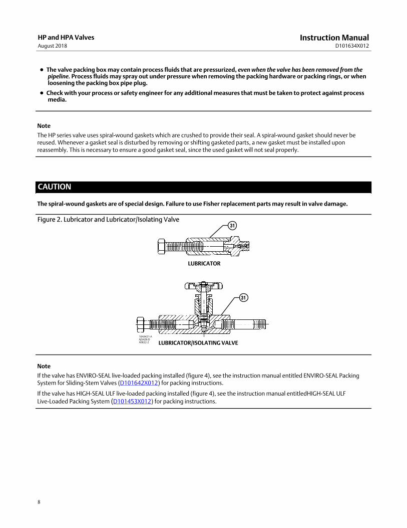
Figure 2. Lubricator and Lubricator/Isolating Valve
LUBRICATOR
LUBRICATOR/ISOLATING VALVE
10A9421‐AAJ5428‐DA0832‐2
31
31
Note
If the valve has ENVIRO‐SEAL live‐loaded packing installed (figure 4), see the instruction manual entitled ENVIRO‐SEAL PackingSystem for Sliding‐Stem Valves (D101642X012) for packing instructions.
If the valve has HIGH‐SEAL ULF live‐loaded packing installed (figure 4), see the instruction manual entitledHIGH‐SEAL ULF
Live‐Loaded Packing System (D101453X012) for packing instructions.

Instruction ManualD101634X012
HP and HPA ValvesAugust 2018
9
Packing Lubrication
CAUTION
Do not lubricate graphite packing. Graphite packing is self-lubricated. Additional lubrication may result in slip-stickmovement of the valve.
Note
To avoid lubricants breaking down at elevated temperatures, do not lubricate packing used in processes with temperatures over260�C (500�F).
WARNING
Do not lubricate parts when used in oxygen service, or where the lubrication is incompatible with the process media. Anyuse of lubricant can lead to the sudden explosion of media due to the oil/oxygen mixture, causing personal injury orproperty damage.
If a lubricator or lubricator/isolating valve (figure 2) is provided for PTFE/composition or other packings that requirelubrication, it will be installed in place of the pipe plug (key 31, figure 23, 24, 25, or 27). Use a good quality silicon‐baselubricant. Packing used in oxygen service or in processes with temperatures over 260�C (500�F) should not belubricated. To operate the lubricator, turn the cap screw clockwise to force the lubricant into the packing box. Thelubricator/isolating valve operates the same way except the isolating valve must first be opened and then closed afterlubrication is completed.
Packing Maintenance
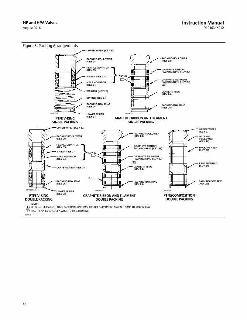
If there is undesirable packing leakage in the spring‐loaded PTFE V‐ring packing shown in figure 3, tighten the packingflange nuts (key 21, figure 23, 24, 25, or 27) until the shoulder on the packing follower (key 28, figure 23, 24, 25, or27) contacts the bonnet (key 18, figure 23, 24, 25, or 27). If leakage continues, replace the packing by following thenumbered steps presented in the replacing packing procedure.
If there is undesirable packing leakage with other than spring‐loaded PTFE V‐ring packing, first try to limit the leakageand establish a stem seal by tightening the packing flange nuts (key 21, figure 23, 24, 25, or 27) to at least theminimum recommended torque in table 7. However, do not exceed the maximum recommended torque in table 7 orexcessive friction may result. If leakage continues, replace the packing by following the numbered steps presented inthe Replacing Packing procedure.
If the packing is relatively new and tight on the valve plug stem, and if tightening the packing flange nuts does not stopthe leakage, it is possible that the stem is worn or nicked so that a seal cannot be made. The surface finish of a newstem is critical for making a good packing seal. If the leakage comes from the outside diameter of the packing, it ispossible that the leakage is caused by nicks or scratches around the packing box wall. While replacing the packingaccording to the Replacing Packing procedure, inspect the valve plug stem and packing box wall for nicks or scratches.
Instruction ManualD101634X012
HP and HPA ValvesAugust 2018
10
Figure 3. Packing ArrangementsUPPER WIPER (KEY 27)
PACKING FOLLOWER(KEY 28)
FEMALE ADAPTOR(KEY 35)
V-RING (KEY 23)
MALE ADAPTOR(KEY 34)
WASHER (KEY 25)
SPRING (KEY 24)
PACKING BOX RING(KEY 26)
LOWER WIPER(KEY 33)
PACKING FOLLOWER(KEY 28)
PACKING BOX RING(KEY 26)
LANTERN RING(KEY 24)
GRAPHITE FILAMENTPACKING RING (KEY 23)
GRAPHITE RIBBONPACKING RING (KEY 23)
1
2
12A8160-A 14A3412-C
PTFE V‐RINGSINGLE PACKING
GRAPHITE RIBBON AND FILAMENTSINGLE PACKING
}KEY 22
UPPER WIPER (KEY 27)
PACKING FOLLOWER(KEY 28)
FEMALE ADAPTOR(KEY 35)
V-RING (KEY 23)
MALE ADAPTOR(KEY 34)
LANTERN RING (KEY 24)
PACKING BOX RING(KEY 26)
LOWER WIPER(KEY 33)
2
12A7839-A Sht 1 14A3414-C
PTFE V‐RINGDOUBLE PACKING
}KEY 22
GRAPHITE RIBBON AND FILAMENTDOUBLE PACKING
1
1
PACKING FOLLOWER(KEY 28)
PACKING BOX RING(KEY 26)
LANTERN RING(KEY 24)
GRAPHITE FILAMENTPACKING RING (KEY 23)
GRAPHITE RIBBONPACKING RING (KEY 23)
UPPER WIPER(KEY 27)
PACKINGFOLLOWER(KEY 28)
PACKING BOX RING(KEY 26)
LANTERN RING(KEY 24)
PACKING RING(KEY 23)
12A8163-A
PTFE/COMPOSITIONDOUBLE PACKING
NOTES:0.102 mm (0.004 INCH) THICK SACRIFICIAL ZINC WASHERS. USE ONLY ONE BELOW EACH GRAPHITE RIBBON RING.
HAS THE APPEARANCE OF A WOVEN OR BRAIDED RING.
1
2
C0747‐1

Instruction ManualD101634X012
HP and HPA ValvesAugust 2018
11
Figure 4. Live‐Loaded Packing
A6297-1
Typical HIGH‐SEAL Graphite ULFPacking System
Typical ENVIRO‐SEAL Packing Systemwith PTFE Packing
Typical ENVIRO‐SEAL Packing Systemwith Graphite ULF Packing
Typical ENVIRO‐SEAL Packing Systemwith Duplex Packing
200
212
201
215
216
207
209
211
217
207
207
207
214
213
A6722
PACKINGRING(KEY 209)
PACKINGRING(KEY 210)
PACKINGBOX RING(KEY 211)
STUD(KEY 200)
SPRINGPACK
ASSEMBLY(KEY 217)
HEX NUT(KEY 212)
PACKINGFLANGE(KEY 201)
GUIDEBUSHING(KEY 207)
PACKINGWASHERS(KEY 214)
GUIDEBUSHING(KEY 208)
39B4612/A
39B4153-A
(KEY 214)

Instruction ManualD101634X012
HP and HPA ValvesAugust 2018
12
Adding Packing Rings
Key numbers referred to in this procedure are shown in figures 23, 24, 25, or 27, unless otherwise indicated.
When using packing with a lantern ring (key 24) it may be possible to add packing rings above the lantern ring as atemporary measure without removing the actuator from the valve body.
1. Isolate the control valve from the line pressure, release pressure from both sides of the valve body, and drain theprocess media from both sides of the valve. If using a power actuator, also shut‐off all pressure lines to the poweractuator, release all pressure from the actuator. Use lock‐out procedures to be sure that the above measures stay ineffect while you work on the equipment.
2. Remove the packing flange nuts (key 21) and lift the packing flange, upper wiper, and packing follower (keys 19, 27,and 28) away from the valve body.
3. It may be possible to dig out the old packing rings on top of the lantern ring, but use care to avoid scratching thevalve plug stem or packing box wall. Clean all metal parts to remove particles that would prevent the packing fromsealing.
4. Remove the stem connector and slip the packing rings over the end of the valve plug stem.
5. Reassemble the packing follower, upper wiper, packing flange, and packing flange nuts (keys 28, 27, 19, and 21).
6. Reconnect the body‐actuator stem connection according to the appropriate actuator instruction manual.
7. Tighten the packing flange nuts only far enough to stop leakage under operating conditions. Check for leakagearound the packing follower when the valve is being put into service. Retighten the packing flange nuts as required(see table 7).
Replacing Packing
WARNING
Refer to the WARNING at the beginning of the Maintenance section in this instruction manual.
Key numbers referred to in this procedure are shown in figures 23, 24, 25, or 27, unless otherwise indicated.
1. Isolate the control valve from the line pressure, release pressure from both sides of the valve body, and drain theprocess media from both sides of the valve. If using a power actuator, also shut‐off all pressure lines to the poweractuator, release all pressure from the actuator. Use lock‐out procedures to be sure that the above measures stay ineffect while you work on the equipment.
2. Remove the cap screws in the stem connector, and separate the two halves of the stem connector. Then exhaust allactuator pressure, if any was applied, and disconnect the actuator supply and any leakoff piping.
3. Remove either the yoke locknut (key 32) or the hex nuts (key 30), and remove the actuator from the bonnet (key 18).
4. Loosen the packing flange nuts (key 21) so that the packing (keys 22, 23, 209, or 210, figure 3) is not tight on thevalve plug stem (key 6). Remove any travel indicator disk and stem locknuts from the valve plug stem threads.
CAUTION
When lifting the bonnet (key 18), be sure that the valve plug and stem assembly (keys 5 and 6) remains on the seat ring(key 4). This avoids damage to the seating surfaces as a result of the assembly dropping from the bonnet after being liftedpart way out. The parts are also easier to handle separately.
Use care to avoid damaging gasket sealing surfaces.

Instruction ManualD101634X012
HP and HPA ValvesAugust 2018
13
The HPD and HPAD piston rings (key 8) are brittle and in two pieces. Avoid damaging the piston rings by dropping or roughhandling.
WARNING
To avoid personal injury or property damage caused by uncontrolled movement of the bonnet, loosen the bonnet byfollowing the instructions in the next step. Do not remove a stuck bonnet by pulling on it with equipment that can stretchor store energy in any other manner. The sudden release of stored energy can cause uncontrolled movement of the bonnet.If the cage sticks to the bonnet, proceed carefully with bonnet removal and support the cage so that it will not fallunexpectedly from the bonnet.
Note
The following step also provides additional assurance that the valve body fluid pressure has been relieved.
5. Hex nuts (key 14) attach the bonnet to the valve body. Loosen these nuts or cap screws approximately 3 mm (1/8inch). Then loosen the body‐to‐bonnet gasketed joint by either rocking the bonnet or prying between the bonnetand valve body. Work the prying tool around the bonnet until the bonnet loosens. If no fluid leaks from the joint,proceed to the next step.
6. Unscrew the hex nuts (key 14) and carefully lift the bonnet off the valve stem. If the valve plug and stem assemblystarts to lift with the bonnet, use a brass or lead hammer on the end of the stem and tap it back down. Set thebonnet on a cardboard or wooden surface to prevent damage to the bonnet gasket surface.
7. Remove the valve plug (key 5), bonnet gasket (key 11), cage (key 2), seat ring (key 4), and the seat ring gasket (key 12).
CAUTION
Inspect the seat ring, cage, bonnet, and body gasket surfaces. These surfaces must be in good condition, with all foreignmaterial removed. Small burrs less than approximately 0.076 mm (0.003 inches) in height (the thickness of a human hair)can be ignored. Scratches or burrs that run across the serrations are not permitted under any conditions, since they willprevent the gaskets from sealing properly.
8. Clean all gasket surfaces with a good wire brush. Clean in the same direction as the surface serrations, not acrossthem.
9. Cover the opening in the valve body to protect the gasket surface and to prevent foreign material from getting intothe valve body cavity.
10. Remove the packing flange nuts (key 21), packing flange (key 19), upper wiper (key 27), and packing follower (key 28). Carefully push out all the remaining packing parts from the valve side of the bonnet using a rounded rod orother tool that will not scratch the packing box wall. For extension bonnets, also remove the baffle (key 36 ) andretaining ring (key 37).
11. Clean the packing box and the following metal packing parts: packing follower, packing box ring (key 26), spring orlantern ring (key 24), and, for single arrangements of PTFE V‐ring packing only, special washer (key 25).
12. Inspect the valve stem threads for any sharp edges that might cut the packing. A whetstone or emery cloth may beused to smooth the threads if necessary.
Instruction ManualD101634X012
HP and HPA ValvesAugust 2018
14
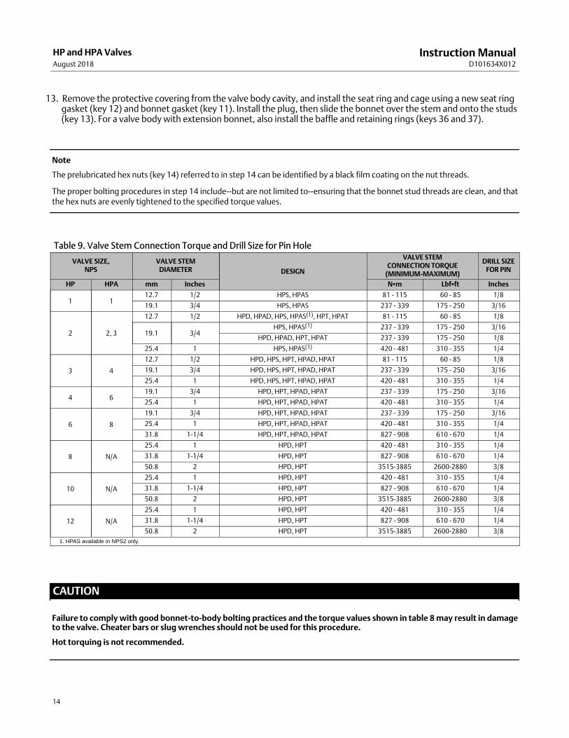
13. Remove the protective covering from the valve body cavity, and install the seat ring and cage using a new seat ringgasket (key 12) and bonnet gasket (key 11). Install the plug, then slide the bonnet over the stem and onto the studs(key 13). For a valve body with extension bonnet, also install the baffle and retaining rings (keys 36 and 37).
Note
The prelubricated hex nuts (key 14) referred to in step 14 can be identified by a black film coating on the nut threads.
The proper bolting procedures in step 14 include‐‐but are not limited to‐‐ensuring that the bonnet stud threads are clean, and thatthe hex nuts are evenly tightened to the specified torque values.
Table 9. Valve Stem Connection Torque and Drill Size for Pin Hole
VALVE SIZE,NPS
VALVE STEMDIAMETER DESIGN
VALVE STEMCONNECTION TORQUE
(MINIMUM‐MAXIMUM)
DRILL SIZEFOR PIN
HP HPA mm Inches N�m Lbf�ft Inches
1 112.7 1/2 HPS, HPAS 81 ‐ 115 60 ‐ 85 1/8
19.1 3/4 HPS, HPAS 237 ‐ 339 175 ‐ 250 3/16
2 2, 3
12.7 1/2 HPD, HPAD, HPS, HPAS(1), HPT, HPAT 81 ‐ 115 60 ‐ 85 1/8
19.1 3/4HPS, HPAS(1) 237 ‐ 339 175 ‐ 250 3/16
HPD, HPAD, HPT, HPAT 237 ‐ 339 175 ‐ 250 1/8
25.4 1 HPS, HPAS(1) 420 ‐ 481 310 ‐ 355 1/4
3 4
12.7 1/2 HPD, HPS, HPT, HPAD, HPAT 81 ‐ 115 60 ‐ 85 1/8
19.1 3/4 HPD, HPS, HPT, HPAD, HPAT 237 ‐ 339 175 ‐ 250 3/16
25.4 1 HPD, HPS, HPT, HPAD, HPAT 420 ‐ 481 310 ‐ 355 1/4
4 619.1 3/4 HPD, HPT, HPAD, HPAT 237 ‐ 339 175 ‐ 250 3/16
25.4 1 HPD, HPT, HPAD, HPAT 420 ‐ 481 310 ‐ 355 1/4
6 8
19.1 3/4 HPD, HPT, HPAD, HPAT 237 ‐ 339 175 ‐ 250 3/16
25.4 1 HPD, HPT, HPAD, HPAT 420 ‐ 481 310 ‐ 355 1/4
31.8 1‐1/4 HPD, HPT, HPAD, HPAT 827 ‐ 908 610 ‐ 670 1/4
8 N/A
25.4 1 HPD, HPT 420 ‐ 481 310 ‐ 355 1/4
31.8 1‐1/4 HPD, HPT 827 ‐ 908 610 ‐ 670 1/4
50.8 2 HPD, HPT 3515-3885 2600-2880 3/8
10 N/A
25.4 1 HPD, HPT 420 ‐ 481 310 ‐ 355 1/4
31.8 1‐1/4 HPD, HPT 827 ‐ 908 610 ‐ 670 1/4
50.8 2 HPD, HPT 3515-3885 2600-2880 3/8
12 N/A
25.4 1 HPD, HPT 420 ‐ 481 310 ‐ 355 1/4
31.8 1‐1/4 HPD, HPT 827 ‐ 908 610 ‐ 670 1/4
50.8 2 HPD, HPT 3515-3885 2600-2880 3/8
1. HPAS available in NPS2 only.
CAUTION
Failure to comply with good bonnet‐to‐body bolting practices and the torque values shown in table 8 may result in damageto the valve. Cheater bars or slug wrenches should not be used for this procedure.
Hot torquing is not recommended.

Instruction ManualD101634X012
HP and HPA ValvesAugust 2018
15
Note
Stud(s) and nut(s) should be installed such that the manufacturer's trademark and material grade marking is visible, allowing easycomparison to the materials selected and documented in the Emerson/Fisher serial card provided with this product.
WARNING
Personal injury or damage to equipment could occur if improper stud and nut materials or parts are used. Do not operate orassemble this product with stud(s) and nut(s) that are not approved by Emerson/Fisher engineering and/or listed on theserial card provided with this product. Use of unapproved materials and parts could lead to stresses exceeding the designor code limits intended for this particular service. Install studs with the material grade and manufacturer's identificationmark visible. Contact your Emerson sales office or Local Business Partner immediately if a discrepancy between actual partsand approved parts is suspected.
14. Lubricate the stud threads and the faces of the hex nuts (key 14) with anti‐seize lubricant (not necessary if newfactory prelubricated hex nuts are used). Replace the hex nuts and tighten them finger‐tight. Stroke the valveseveral times to center the trim. Torque the nuts in a crisscross pattern to no more than 1/4 of the nominal torquevalue specified in table 8.
When all nuts are tightened to that torque value, increase the torque by 1/4 of the specified nominal torque andrepeat the crisscross pattern. Repeat this procedure until all nuts are tightened to the specified nominal value. Applythe final torque value again and, if any nut still turns, tighten every nut again.
Note
When installing packing rings, prevent entrapping air between the rings. Add the rings one at a time without forcing them belowthe chamfer of the packing box entrance chamber. As each successive ring is added, the stack should not be pushed down morethan the thickness of the added ring (figure 5).
15. Install new packing and the metal packing box parts according to the appropriate arrangement in figure 3. Ifdesired, packing parts may be pre‐lubricated with a silicon base grease for easier installation. Slip a smooth‐edgedpipe over the valve stem, and gently tamp each soft packing part into the packing box, being sure that air is nottrapped between adjacent soft parts.
16. Slide the packing follower, wiper, and packing flange into position. Lubricate the packing flange studs (key 20) andthe faces of the packing flange nuts (key 21). Replace the packing flange nuts.
For the spring‐loaded PTFE V‐ring packing shown in figure 3, tighten the packing flange nuts until the shoulder on thepacking follower (key 28) contacts the bonnet.

Instruction ManualD101634X012
HP and HPA ValvesAugust 2018
16
Figure 5. Installing Graphite Ribbon/Filament Packing Rings One at a Time
VALVE STEM
PACKING FOLLOWER
BONNET
TOP OFPACKING RINGEVEN WITHBOTTOM OFENTRANCECHAMFER
INSTALLINGSECOND PACKING RING
A2207‐2
INSTALLINGFIRST PACKING RING
For graphite packing, tighten the packing flange nuts to the maximum recommended torque shown in table 7. Then,loosen the packing flange nuts, and retighten them to the recommended minimum torque shown in table 7.
For other packing types, tighten the packing flange nuts alternately in small equal increments until one of the nutsreaches the minimum recommended torque shown in table 7. Then, tighten the remaining flange nuts until thepacking flange is level and at a 90‐degree angle to the valve stem.
For ENVIRO‐SEAL or HIGH‐SEAL live‐loaded packing, refer to the note at the beginning of the Maintenance section.
17. Mount the actuator on the valve body assembly, and reconnect the actuator and valve plug stems according to theprocedures in the appropriate actuator instruction manual.
Trim RemovalFor C‐seal construction, see the appropriate C‐seal sections in this manual. For bore seal construction, see the appropriate bore seal sections in this manual.
Key numbers referenced in this procedure are shown in figure 23, 24, 25, or 27 except where indicated.
1. Remove the actuator and bonnet by following steps 1 through 6 of the replacing packing procedure. Observe allwarnings and cautions.
2. Lift the valve stem and attached valve plug out of the valve body. If the valve plug is to be reused, tape or otherwiseprotect the valve plug stem and the valve plug seating surface to prevent scratches.
3. Lift out the cage (key 2) and the bonnet gasket (key 11). For an NPS 2 valve body with a Cavitrol III two stage cage,also remove the bonnet spacer and two gaskets. For NPS 8 to 12 HPD and HPT, follow step 4 to lift the cage.
4. Install threaded rods (about 6” long) in to the holes on the top of the cage. Install hoist rings, nuts or eye bolt on tothe threaded rod. Lift the cage with the hoist nut from the valve body.
Instruction ManualD101634X012
HP and HPA ValvesAugust 2018
17
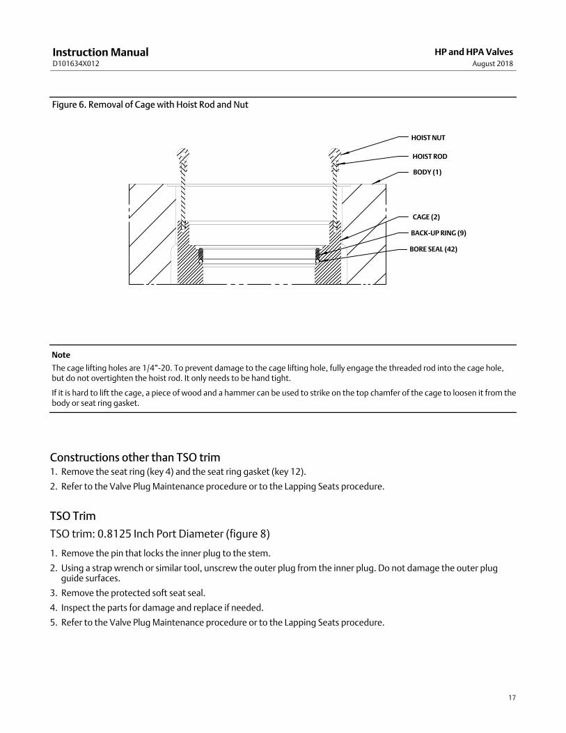
Figure 6. Removal of Cage with Hoist Rod and Nut
HOIST NUT
CAGE (2)
BODY (1)
HOIST ROD
BACK-UP RING (9)
BORE SEAL (42)
Note
The cage lifting holes are 1/4”-20. To prevent damage to the cage lifting hole, fully engage the threaded rod into the cage hole,but do not overtighten the hoist rod. It only needs to be hand tight.
If it is hard to lift the cage, a piece of wood and a hammer can be used to strike on the top chamfer of the cage to loosen it from thebody or seat ring gasket.
Constructions other than TSO trim1. Remove the seat ring (key 4) and the seat ring gasket (key 12).
2. Refer to the Valve Plug Maintenance procedure or to the Lapping Seats procedure.
TSO Trim
TSO trim: 0.8125 Inch Port Diameter (figure 8)
1. Remove the pin that locks the inner plug to the stem.
2. Using a strap wrench or similar tool, unscrew the outer plug from the inner plug. Do not damage the outer plugguide surfaces.
3. Remove the protected soft seat seal.
4. Inspect the parts for damage and replace if needed.
5. Refer to the Valve Plug Maintenance procedure or to the Lapping Seats procedure.
Instruction ManualD101634X012
HP and HPA ValvesAugust 2018
18
TSO trim: 1.6875 Inch Port Diameter (figure 9)
1. Remove the retainer, backup ring, anti‐extrusion rings, and piston ring.
2. Remove the set screws that lock the outer plug to the stem.
3. Using a strap wrench or similar tool, unscrew the outer plug from the inner plug. Do not damage the outer plugguide surfaces.
4. Remove the protected soft seat seal.
5. Inspect the parts for damage and replace if needed.
6. Refer to the Valve Plug Maintenance procedure or to the Lapping Seats procedure.
TSO trim: 2.6875 Inch and Larger Port Diameters (figure 10)
1. Remove the retainer, backup ring, anti‐extrusion rings, and piston ring.
2. Remove the set screws that lock the outer plug to the inner plug.
3. Using a strap wrench or similar tool, unscrew the outer plug from the inner plug. Do not damage the outer plugguide surfaces.
4. Remove the protected soft seat seal.
5. Inspect the parts for damage and replace if needed.
6. Refer to the Valve Plug Maintenance procedure or to the Lapping Seats procedure.
Valve Plug MaintenanceKey numbers used in this procedure are shown in figure 23, 24, 25 or 27, except where indicated.
1. With the valve plug (key 5) removed according to the trim removal procedure, proceed as appropriate:
For HPD and HPAD valves, the piston rings (key 8) are each in at least two sections; remove the sections from thegrooves in the valve plug.
For HPS and HPAS valves, proceed to step 2.
For HPT and HPAT valves, work the retaining ring (key 10) off the valve plug with a screwdriver. Carefully slide thebackup ring and seal ring (keys 9 and 8) off the valve plug.
2. To replace the valve plug stem (key 6), drive out the pin (key 7), and unscrew the stem from the valve plug.
CAUTION
Never reuse an old stem with a new valve plug. Using an old stem with a new plug requires drilling a new pin hole in thestem. This weakens the stem and may cause the stem to fail in service. If a new valve plug is required, always order a valveplug, stem, and pin as an assembly. Specify the correct part number of each of the three parts, but state that the parts arebeing ordered as an assembly.
A used valve plug may be reused with a new stem.
Instruction ManualD101634X012
HP and HPA ValvesAugust 2018
19
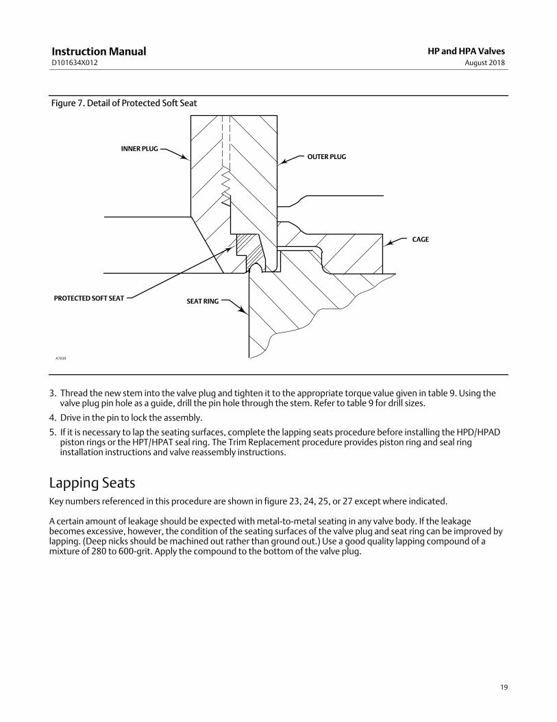
Figure 7. Detail of Protected Soft Seat
INNER PLUGOUTER PLUG
CAGE
SEAT RINGPROTECTED SOFT SEAT
A7039
3. Thread the new stem into the valve plug and tighten it to the appropriate torque value given in table 9. Using thevalve plug pin hole as a guide, drill the pin hole through the stem. Refer to table 9 for drill sizes.
4. Drive in the pin to lock the assembly.
5. If it is necessary to lap the seating surfaces, complete the lapping seats procedure before installing the HPD/HPADpiston rings or the HPT/HPAT seal ring. The Trim Replacement procedure provides piston ring and seal ringinstallation instructions and valve reassembly instructions.
Lapping SeatsKey numbers referenced in this procedure are shown in figure 23, 24, 25, or 27 except where indicated.
A certain amount of leakage should be expected with metal‐to‐metal seating in any valve body. If the leakagebecomes excessive, however, the condition of the seating surfaces of the valve plug and seat ring can be improved bylapping. (Deep nicks should be machined out rather than ground out.) Use a good quality lapping compound of amixture of 280 to 600‐grit. Apply the compound to the bottom of the valve plug.

Instruction ManualD101634X012
HP and HPA ValvesAugust 2018
20
Figure 8. Typical Unbalanced TSO Trim Assembly, Small Port Designs (0.8125 Inch Port Diameter)
OUTER PLUG
PIN
INNER PLUG
PROTECTED SOFT SEAT
A7111

Instruction ManualD101634X012
HP and HPA ValvesAugust 2018
21
Note
HP Series valves use spiral‐wound gaskets. These gaskets provide their seal by being crushed and therefore should never bereused. This includes reusing a gasket after the lapping procedure has been performed.
An “old” gasket can be used to lap the seat, however the gasket must be replaced with a new gasket.
To preserve the effects of lapping, do not change either the position of the seat ring in the valve body cavity or the position of thecage on the seat ring after lapping the seating surfaces. When the parts are removed for cleaning and replacement of the “old”gaskets, return them to the original positions.
Figure 9. Typical Balanced TSO Trim (1.6875 Inch Port Diameter)
VALVEPLUGSEAL
PROTECTEDSOFT SEAT
A7112
Use the following procedure to lap the seating surfaces.
1. Install the following parts according to the instructions presented in the trim replacement procedure: “old” seatring gasket (key 12), seat ring (key 4), cage (key 2), and “old” bonnet gasket(key 11).
2. Proceed as appropriate:
For an HPD, HPAD, HPT, or HPAT valve, install the valve plug and stem assembly (keys 5 and 6)‐‐without piston ringsor seal ring (key 8) ‐‐into the cage.
For an HPS or HPAS valve, install the valve plug and stem assembly (keys 5 and 6) into the cage.
3. Install the bonnet (key 18) over the valve stem, and secure the bonnet with four of the hex nuts (key 14).

Instruction ManualD101634X012
HP and HPA ValvesAugust 2018
22
4. Attach a handle, such as a piece of strap iron secured by stem locknuts, to the valve stem. Rotate the handlealternately in each direction to lap the seats.
5. After lapping, disassemble as necessary (you may mark the position of the seat ring and cage with a soft tipmarker). Clean the seating surfaces, replace the gaskets, reassemble (taking care to return the seat ring and cage totheir original positions), and test for shutoff. Repeat the lapping procedure if necessary.
Figure 10. Typical Balanced TSO Trim, Large Port Designs (2.6875 Inch and Larger Port Diameters)
VALVE PLUGSEAL
PROTECTEDSOFT SEAT
A7096

Instruction ManualD101634X012
HP and HPA ValvesAugust 2018
23
Table 10. Actuator Groups by Type NumberGroup 1
71 & 90 mm (2‐13/16 & 3‐9/16 Inch) Yoke BossGroup 100
127 mm (5‐Inch) Yoke Boss
472 & 473585C
1B644 & 645
655657 & 667
685SE & 685SR1008
472473474476
585C657685
Biffi PLA/PLAS
Group 101127 mm (5‐Inch) Yoke Boss
667
Group 407 127 mm (5-Inch) Yoke Boss
Group 802127 mm (5-Inch) Yoke Boss
585C657685
Biffi PLA/PLAS
585C685
Biffi PLA/PLAS
Group 805178 mm (7-Inch) Yoke Boss
685Biffi PLA/PLAS
Trim Replacement
WARNING
Observe the warning at the start of the Maintenance section.
After all trim maintenance has been completed, reassemble the valve body by following the numbered steps below. Becertain that all gasketed surfaces have been well cleaned. Key numbers referenced in this procedure are shown infigure 23, 24, 25, or 27, except where indicated.
CAUTION
Inspect the seat ring, cage, bonnet, and body gasket surfaces. These surfaces must be in good condition, with all foreignmaterial removed. Small burrs less than approximately 0.076 mm (0.003 inches) in height (the thickness of a human hair)can be ignored. Scratches or burrs that run across the serrations are not permitted under any conditions, since they willprevent the gaskets from sealing properly.
CAUTION
The pressure balancing holes in the valve plug are necessary for the proper and safe operation of the valve. Inspect thebalancing holes every time the valve is disassembled for service. Any build-up, blockage, or clogging of the balance holesshould be removed.
Instruction ManualD101634X012
HP and HPA ValvesAugust 2018
24
NPS 2 to 6 HPD, HPT and NPS 2 to 8 HPAD, HPAT
Constructions other than TSO trim
Note
When installing the standard cage, align two of the holes in the cage with the centerline of the valve body. Refer to figure 24.
1. Install the seat ring gasket (key 12) into the valve body. Install the seat ring (key 4).
2. Install the cage.
3. To install the piston rings and seal rings (key 8), proceed as appropriate:
For an HPD or HPAD valve, if it is necessary to install new piston rings, the replacement piston rings will arrive in onepiece. Use a vise with smooth or taped jaws to break a replacement piston ring into halves. Place the new ring in thevise so that the jaws compress the ring into an oval. Compress the ring slowly until the ring snaps on both sides. If oneside snaps first, do not try to tear or cut the other side. Instead, keep compressing until the other side snaps. Thepiston ring can also be fractured by scoring and snapping over a hard surface such as a table edge. Sawing or cutting isnot recommended.
Remove any protective tape or covering from the valve plug and stem assembly, and set it on a protective surface.Then, place the piston rings in the piston ring grooves with the fractured ends matched.
For an HPT or HPAT valve, install the seal ring (key 8) onto the valve plug (key 5). Install the ring with the open sidefacing the seat ring end of the valve plug for flow‐down applications (view A of figure 26) or with the open side facingthe valve plug stem end of the valve plug for flow‐up applications (view B of figure 26). Slide the backup ring (key 9)onto the valve plug. Secure with the retaining ring (key 10).
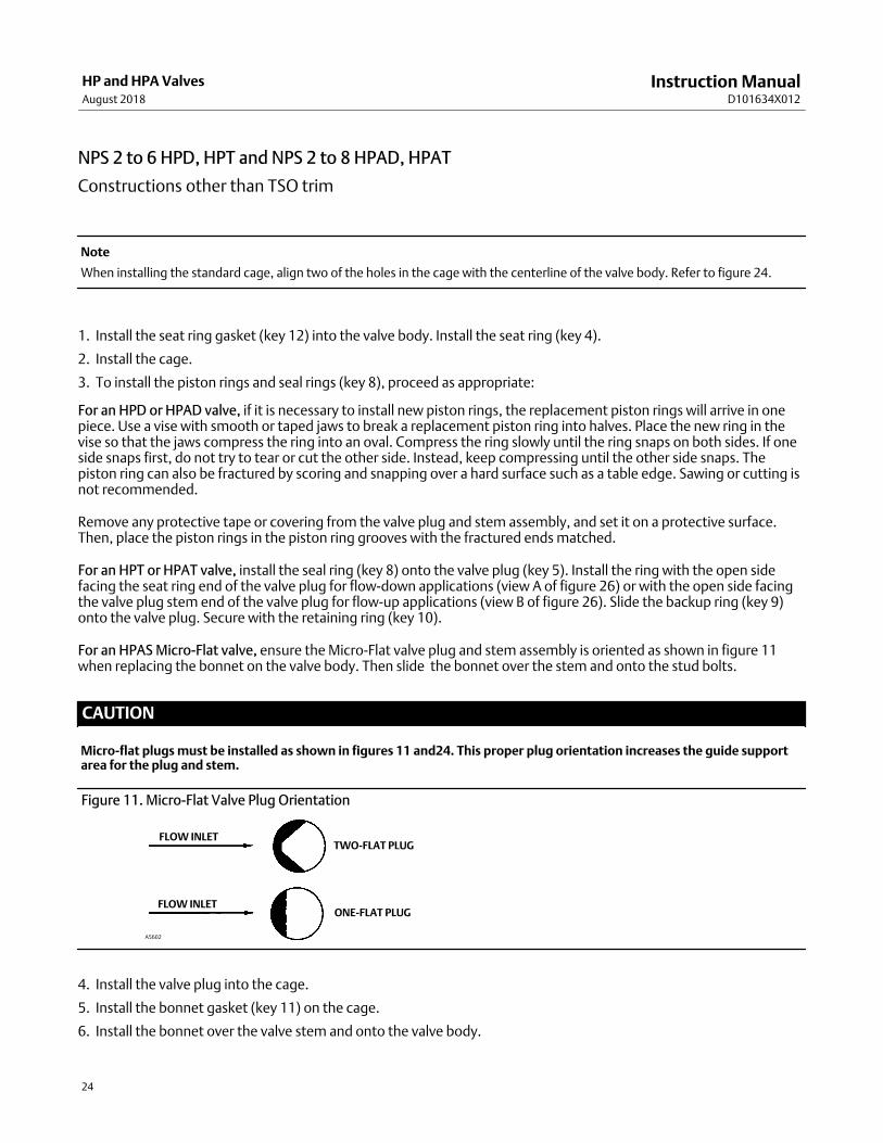
For an HPAS Micro-Flat valve, ensure the Micro-Flat valve plug and stem assembly is oriented as shown in figure 11when replacing the bonnet on the valve body. Then slide the bonnet over the stem and onto the stud bolts.
CAUTION
Micro-flat plugs must be installed as shown in figures 11 and24. This proper plug orientation increases the guide supportarea for the plug and stem.
Figure 11. Micro-Flat Valve Plug Orientation
A5602
FLOW INLET
FLOW INLET
TWO-FLAT PLUG
ONE-FLAT PLUG
4. Install the valve plug into the cage.
5. Install the bonnet gasket (key 11) on the cage.
6. Install the bonnet over the valve stem and onto the valve body.

Instruction ManualD101634X012
HP and HPA ValvesAugust 2018
25
TSO Trim
TSO trim: 0.8125 Inch Port Diameter (figure 8)
1. Thread the outer plug onto the inner plug until the parts seat metal to metal, using a strap wrench or similar toolthat will not damage the outer plug guide surfaces.
2. Mark the inner plug and outer plug with alignment marks in the assembled position.
3. Disassemble the outer plug from the inner plug and install the seal over the inner plug, so that the seal rests belowthe threaded area.
4. Thread the outer plug onto the inner plug and tighten with a strap wrench or similar tool until the alignment marksline up. This will ensure that the plug parts are metal to metal and the seal is compressed properly. Do not damagethe outer plug guide surfaces.
5. Drill through the inner plug with the proper size drill bit (same size as stem pinning) and install the pin.
6. Install the bonnet gasket (key 11) on the cage.
7. Install the bonnet over the valve stem and onto the valve body.
TSO trim: 1.6875 Inch Port Diameter (figure 9)
1. Thread the outer plug onto the inner plug until the parts seat metal to metal, using a strap wrench or similar toolthat will not damage the outer plug guide surfaces.
2. Mark the top of the outer plug and stem with alignment marks in the assembled position.
3. Disassemble the outer plug from the inner plug and install the seal over the inner plug, so that the seal rests belowthe threaded area.
4. Thread the outer plug onto the inner plug and tighten with a strap wrench or similar tool until the alignment marksline up. This will ensure that the plug parts are metal to metal and the seal is compressed properly. Do not damagethe outer plug guide surfaces.
5. Install set screws centering the stem in the outer plug and torque to 11 N�m (8 lbf�ft).
6. Assemble the piston ring, anti‐extrusion rings, backup ring, and retainer.
7. Install the bonnet gasket (key 11) on the cage.
8. Install the bonnet over the valve stem and onto the valve body.
TSO trim: 2.6875 Inch and Larger Port Diameters (figure 10)
1. Thread the outer plug onto the inner plug until the parts seat metal to metal, using a strap wrench or similar toolthat will not damage the outer plug guide surfaces.
2. Mark the top of the inner plug and outer plug with alignment marks in the assembled position.
3. Disassemble the outer plug from the inner plug and install the seal over the inner plug, so that the seal rests belowthe threaded area.
4. Thread the outer plug onto the inner plug and tighten with a strap wrench or similar tool until the alignment marksline up. This will ensure that the plug parts are metal to metal and the seal is compressed properly. Do not damagethe outer plug guide surfaces.
5. Install set screws centering the inner plug in the outer plug and torque to 11 N�m (8 lbf�ft).
6. Assemble the piston ring, anti‐extrusion rings, backup ring, and retainer.
7. Install the bonnet gasket (key 11) on the cage.
8. Install the bonnet over the valve stem and onto the valve body.
NPS 8 to 12 HPD, HPT Constructions (figure 27 and 28)1. Install the seat ring flat sheet gasket (key 12) in the lower gasket groove in the valve body (key 1), making sure the
gasket is centered in the groove and the bottom of the gasket is flush with the mating surface in the body.

Instruction ManualD101634X012
HP and HPA ValvesAugust 2018
26
2. If required, slip quantity-1 seal ring (key 42) onto the lowest groove of cage with the open side of the seal ringfacing the top or bottom of the seat ring, depending on flow direction. Make sure the anti-extrusion ring is on theclosed side of the seal ring and the tapered face of anti-extrusion ring and the seal ring match correctly, see figure12.
Figure 12. Soft Seal Detail and Installed Orientation
SEAL RING (42)(OPEN SIDE DOWN)ANTI-EXTRUSION
RING (42)
BONNET (18)
PLUG (5)
PLUG
GASKET(43)
CAGE (2)
GASKET (43)
CAGE (2)
BONNET (18)
PLUG (5)
SEAL RING (42)(OPEN SIDE UP)
PISTON RING (8)
(a) FLOW UP
BACK-UP RING (9) BACK-UP RING (9)
PISTON RING (8)
(b) FLOW DOWN
ANTI-EXTRUSIONRING (42)
ANTI-EXTRUSION RING
CAGE
SEAL JACKET
SEAL SPRING
Note
The anti-extrusion ring is NOT reversible. There is a flat face side and a tapered face side. The tapered face side of the anti-extrusionring matches a tapered face on the seal ring. The seal will not function properly if it is not assembled correctly. The seal installationshould be done prior to cage installed into the valve. When install a bore seal ring, refer to the bore seal Trim section.
3. Place the backup ring (key 9) into the seal groove until it touches the seal ring (key 42).
4. Install threaded rods (about 6” long) in to the holes on the top of the cage. Install hoist rings, nuts or eye bolt on tothe threaded rod.
Note
The cage lifting holes are 1/4”-20. To prevent damage to the cage lifting hole, fully engage the threaded rod into the cage hole,but do not overtighten the hoist rod. It only needs to be hand tight.

Instruction ManualD101634X012
HP and HPA ValvesAugust 2018
27
5. Install the cage (key 2) into the valve body, lift the cage using the hoist rings on the threaded rods. When installingthe cage (key 2), take care to lower the cage evenly and ensure that cage (key 2) will not damage the flat sheetgasket (key 12).
Figure 13. Installation of Cage with Hoist Rod and Nut
HOIST NUT
CAGE (2)
BODY (1)
HOIST ROD
BACK-UP RING (9)
BORE SEAL (42)
Note
If a drilled hole cage is used, blow out the cage and drilled holes before installing into the body to make sure the burrs and debriswill not be trapped between cage and plug and cause damage.
6. Install qty-3 cage spiral wound gasket (key 43) in the gasket groove on top of the cage (key 2), making sure thegaskets sit flush on the surface of the groove.
7. Install the bonnet gasket (key 11) in to the groove around the valve body trim opening.
8. Lower the bonnet over the valve plug stem, ensuring the valve stem is centered with the bonnet. This is importantso that the top of the stem will engage the packing bore hole in the Bonnet. Depending on the valve size and travel,the plug stem may engage the packing bore before the bonnet skirt engages with the valve body opening.
Note
Be careful to prevent the bonnet skirt from crushing the body gasket as the bonnet is lowered on to the valve. To prevent crushingthe gasket accidentally, it is acceptable to raise the gasket up around the bonnet skirt as the bonnet is lowered into to valveopening.
Damaging the gaskets will require that they are replaced.
Note
The prelubricated hex nuts (key 14) referred to in step 9 can be identified by a black film coating on the nut threads.
The proper bolting procedures in step 9 include‐‐but are not limited to‐‐ensuring that the bonnet stud threads are clean, and thatthe hex nuts are evenly tightened to the specified torque values.

Instruction ManualD101634X012
HP and HPA ValvesAugust 2018
28
CAUTION
Failure to comply with good bonnet‐to‐body bolting practices and the torque values shown in table 8 may result in damageto the valve. Cheater bars or slug wrenches should not be used for this procedure.
Hot torquing is not recommended.
Note
Stud(s) and nut(s) should be installed such that the manufacturer's trademark and material grade marking is visible, allowing easycomparison to the materials selected and documented in the Emerson/Fisher serial card provided with this product.
WARNING
Personal injury or damage to equipment could occur if improper stud and nut materials or parts are used. Do not operate orassemble this product with stud(s) and nut(s) that are not approved by Emerson/Fisher engineering and/or listed on theserial card provided with this product. Use of unapproved materials and parts could lead to stresses exceeding the designor code limits intended for this particular service. Install studs with the material grade and manufacturer's identificationmark visible. Contact your Emerson sales office or Local Business Partner immediately if a discrepancy between actual partsand approved parts is suspected.
9. Lubricate the stud threads and the faces of the hex nuts (key 14) with anti‐seize lubricant (not necessary if newfactory prelubricated hex nuts are used). Replace the hex nuts, but do not tighten them. Torque the nuts in acrisscross pattern to no more than 1/4 of the nominal torque value specified in table 8. When all nuts are tightenedto that torque value, increase the torque by 1/4 of the specified nominal torque and repeat the crisscross pattern.Repeat this procedure until all nuts are tightened to the specified nominal value. Apply the final torque value againand, if any nut still turns, tighten every nut again.
10. Install new packing and packing box parts per steps 15 and 16 of the Replacing Packing procedure. Be certain toobserve the note given prior to step 15 of that procedure.
11. Mount the actuator by following the procedures in the actuator instruction manual. Check for packing leakage asthe valve is being put into service. Retorque the packing flange nuts as required (see table 7).
Retrofit: Installing C‐seal Trim
Apply to NPS 2 to 6 HPD, HPT and NPS 2 to 8 HPAD, HPAT Constructions
Note
Additional actuator thrust is required for a valve with C‐seal trim. When installing C‐seal trim in an existing valve, contact yourEmerson sales office or Local Business Partner for assistance in determining new actuator thrust requirements.
Assemble the new valve plug/retainer assembly (with C‐seal plug seal) using the following instructions:
CAUTION
To avoid leakage when the valve is returned to service, use appropriate methods and materials to protect all sealingsurfaces of the new trim parts while assembling the individual parts and during installation in the valve body.

Instruction ManualD101634X012
HP and HPA ValvesAugust 2018
29
1. Apply a suitable high‐temperature lubricant to the inside diameter of the C‐seal plug seal. Also, lubricate theoutside diameter of the valve plug where the C‐seal plug seal must be pressed into the proper sealing position(figure 14).
2. Orient the C‐seal plug seal for correct sealing action based on the process fluid flow direction through the valve.
� The open interior of the C‐seal plug seal must face up in a valve with flow‐up construction (figure 14).
� The open interior of the C‐seal plug seal must face down in a valve with flow‐down construction (figure 14).
Note
An installation tool must be used to properly position the C‐seal plug seal on the valve plug. A tool is available as a Fisher spare partor a tool could be manufactured following the dimensions given in figure 15.
3. Place the C‐seal plug seal over the top of the valve plug and press the C‐seal plug seal onto the plug using the C‐sealinstallation tool. Carefully press the C‐seal plug seal onto the plug until the installation tool contacts the horizontalreference surface of the valve plug (figure 16).
4. Apply a suitable high‐temperature lubricant to the threads on the plug. Then, place the C‐seal retainer onto theplug and tighten the retainer using an appropriate tool such as a strap wrench.
5. Using an appropriate tool such as a center punch, stake the threads on top of the plug in one place (figure 17) tosecure the C‐seal retainer.
6. Install the new plug/retainer assembly with C‐seal plug seal on the new stem following the appropriate instructionsin the Trim Replacement section in this manual.
7. Install piston rings by following instructions in the Trim Replacement section in this manual.
8. Remove the existing valve actuator and bonnet following the appropriate instructions in the Replacing Packingsection in this manual.
Figure 14. HPD with C‐seal Trim
FLOW DOWN FLOW UP
VIEW A
37B1399‐A

Instruction ManualD101634X012
HP and HPA ValvesAugust 2018
30
FOR VALVEPLUGS
FITTINGPORT SIZE
(Inches)
DIMENSIONS, mm(See Drawing Below) Part Number
(To OrderA Tool)
A B C D E F G H
2.875 82.5552.324 ‐52.578
4.978 ‐ 5.029 3.708 ‐ 3.759 41.14852.680 ‐52.781
55.118 ‐55.626
70.891 ‐ 71.044 24B9816X012
3.4375 101.658.674 ‐58.928
4.978 ‐ 5.029 3.708 ‐ 3.759 50.861.011 ‐61.112
63.449 ‐63.957
85.166 ‐ 85.319 24B5612X012
3.625 104.39465.024 ‐65.278
4.978 ‐ 5.029 3.708 ‐ 3.759 50.868.936 ‐69.037
71.374 ‐71.882
89.941 ‐ 90.094 24B3630X012
4.375 125.98483.439 ‐83.693
4.978 ‐ 5.029 3.708 ‐ 3.759 50.887.351 ‐87.452
89.789 ‐90.297
108.991 ‐ 109.144 24B3635X012
5.375 142.748100.076 ‐
100.334.978 ‐ 5.029 3.708 ‐ 3.759 45.974
103.835 ‐103.937
106.274 ‐106.782
128.219 ‐ 128.372 23B9193X012
FOR VALVEPLUGS
FITTINGPORT SIZE
(Inches)
Dimensions, Inches(See Drawing Below) Part Number
(To OrderA Tool)
A B C D E F G H
2.875 3.25 2.060 ‐ 2.070 0.196 ‐ 0.198 0.146 ‐ 0.148 1.62 2.074 ‐ 2.078 2.170 ‐ 2.190 2.791 ‐ 2.797 24B9816X012
3.4375 4.00 2.310 ‐ 2.320 0.196 ‐ 0.198 0.146 ‐ 0.148 2.00 2.402 ‐ 2.406 2.498 ‐ 2.518 3.353 ‐ 3.359 24B5612X012
3.625 4.11 2.560 ‐ 2.570 0.196 ‐ 0.198 0.146 ‐ 0.148 2.00 2.714 ‐ 2.718 2.810 ‐ 2.830 3.541 ‐ 3.547 24B3630X012
4.375 4.96 3.285 ‐ 3.295 0.196 ‐ 0.198 0.146 ‐ 0.148 2.00 3.439 ‐ 3.443 3.535 ‐ 3.555 4.291 ‐ 4.297 24B3635X012
5.375 5.62 3.940 ‐ 3.950 0.196 ‐ 0.198 0.146 ‐ 0.148 1.81 4.088 ‐ 4.092 4.184 ‐ 4.204 5.048 ‐ 5.054 23B9193X012
Figure 15. C‐seal Plug Seal Installation Tool
∅A
∅B
8° - 9°
DC
∅F
∅G
∅H
E
A6777
45° X 1.524 (0.06)
45° X 0.508 (0.02)
BREAK SHARPCORNER45° X 0.254 (0.01)MAX
mm (inch)
Instruction ManualD101634X012
HP and HPA ValvesAugust 2018
31
CAUTION
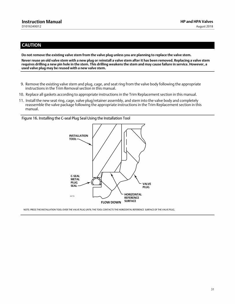
Do not remove the existing valve stem from the valve plug unless you are planning to replace the valve stem.
Never reuse an old valve stem with a new plug or reinstall a valve stem after it has been removed. Replacing a valve stemrequires drilling a new pin hole in the stem. This drilling weakens the stem and may cause failure in service. However, aused valve plug may be reused with a new valve stem.
9. Remove the existing valve stem and plug, cage, and seat ring from the valve body following the appropriateinstructions in the Trim Removal section in this manual.
10. Replace all gaskets according to appropriate instructions in the Trim Replacement section in this manual.
11. Install the new seat ring, cage, valve plug/retainer assembly, and stem into the valve body and completelyreassemble the valve package following the appropriate instructions in the Trim Replacement section in thismanual.
Figure 16. Installing the C‐seal Plug Seal Using the Installation Tool
C‐SEALMETALPLUGSEAL
INSTALLATIONTOOL
A6778
VALVEPLUG
HORIZONTALREFERENCESURFACEFLOW DOWN
NOTE: PRESS THE INSTALLATION TOOL OVER THE VALVE PLUG UNTIL THE TOOL CONTACTS THE HORIZONTAL REFERENCE SURFACE OF THE VALVE PLUG.

Instruction ManualD101634X012
HP and HPA ValvesAugust 2018
32
Figure 17. Stake the Threads of the C‐seal Retainer
C‐SEALMETALPLUGSEAL
VALVEPLUG
FLOW DOWN
PISTONRING
RETAINER
DEFORM THREAD TOSTAKE C‐SEAL RETAINER
A6779
CAUTION
To avoid excessive leakage and seat erosion, the valve plug must be initially seated with sufficient force to overcome theresistance of the C‐seal plug seal and contact the seat ring. You can correctly seat the valve plug by using the same forcecalculated for full load when sizing your actuator. With no pressure drop through the valve, this force will adequately drivethe valve plug to the seat ring, thus giving the C‐seal plug seal a predetermined permanent set. Once this is done, theplug/retainer assembly, the cage, and the seat ring become a matched set.
With full actuator force applied and the valve plug fully seated, align the actuator travel indicator scale with the lower endof valve travel. Refer to the appropriate actuator instruction manual for information on this procedure.
Replacement of Installed C‐seal Trim
Apply to NPS 2 to 6 HPD, HPT and NPS 2 to 8 HPAD, HPAT Constructions
Trim Removal (C‐seal Constructions)1. Remove the valve actuator and bonnet following the appropriate instructions in the Replacing Packing section in
this manual.
CAUTION
To avoid leakage when the valve is returned to service, use appropriate methods and materials to protect all sealingsurfaces of the trim parts during maintenance.
Use caution when removing piston ring(s) and C‐seal plug seal to avoid scratching any sealing surface.
Instruction ManualD101634X012
HP and HPA ValvesAugust 2018
33
CAUTION
Do not remove the valve stem from the plug/retainer assembly unless you are planning to replace the valve stem.
Never reuse an old valve stem with a new plug or reinstall a valve stem after it has been removed. Replacing a valve stemrequires drilling a new pin hole in the stem. This drilling weakens the stem and may cause failure in service. However, aused valve plug may be reused with a new valve stem.
2. Remove the plug/retainer assembly (with C‐seal plug seal), cage, and seat ring from the valve body following theappropriate instructions in the Trim Removal section in this manual.
3. Locate the staked thread on top of the valve plug (figure 17). The staked thread secures the retainer. Use a drill witha 1/8 inch bit to drill out the staked area of the thread. Drill approximately 1/8‐inch into the metal to remove thestaking.
4. Locate the break between sections of the piston ring(s). Using an appropriate tool such as a flat‐blade screwdriver,carefully pry out the piston ring(s) from the groove(s) in the C‐seal retainer.
5. After removing the piston ring(s), locate the 1/4‐inch diameter hole in the groove. In a retainer with two piston ringgrooves, the hole will be found in the upper groove.
6. Select an appropriate tool such as a punch and place the tip of the tool into the hole with the body of the tool heldtangent to the outside diameter of the retainer. Strike the tool with a hammer to rotate the retainer and free it fromthe valve plug. Remove the retainer from the plug.
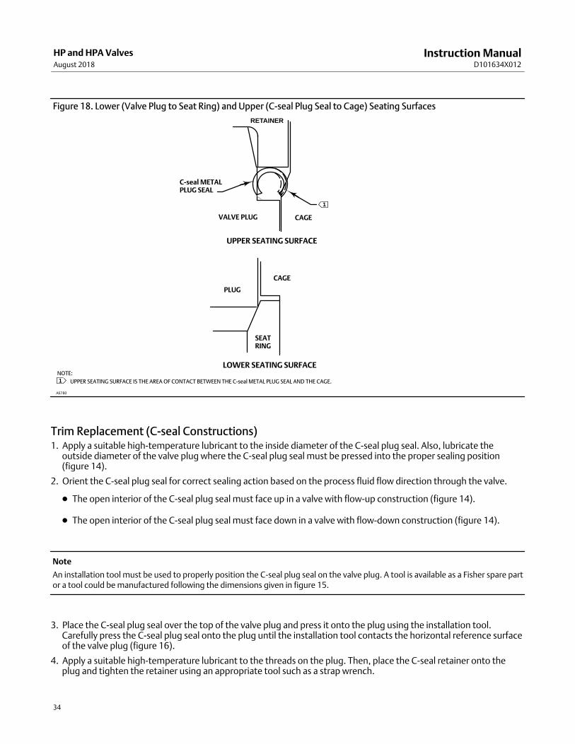
7. Use an appropriate tool such as a flat‐blade screwdriver to pry the C‐seal plug seal off the plug. Use caution to avoidscratches or other damage to the sealing surfaces where the C‐seal plug seal makes contact with the valve plug(figure 18).
8. Inspect the lower seating surface where the valve plug contacts the seat ring for wear or damage which wouldprevent proper operation of the valve. Also, inspect the upper seating surface inside the cage where the C‐seal plugseal contacts the cage, and inspect the sealing surface where the C‐seal plug seal makes contact with the plug(figure 18).
9. Replace or repair trim parts according to the following procedure for Lapping Metal Seats, Remachining MetalSeats, or other valve plug maintenance procedures as appropriate.
Lapping Metal Seats (C‐seal Constructions)
Before installing a new C‐seal plug seal, lap the lower seating surface (valve plug to seat ring, figure 18) followingappropriate procedures in the Lapping Seats section in this manual.
Remachining Metal Seats (C‐seal Constructions)
See figure 19. A valve plug with a C‐seal metal plug seal features two seating surfaces. One seating surface is foundwhere the valve plug contacts the seat ring. The second seating surface is found where the C‐seal plug seal contactsthe upper seating surface in the cage. If you machine the seats on the seat ring and/or plug, you must machine anequal dimension from the seating area in the cage.
CAUTION
If metal is removed from the seat ring and plug and a corresponding amount is not removed from the cage seating area, theC‐seal plug seal will be crushed as the valve closes and the C‐seal retainer will strike the seating area of the cage, preventingthe valve from closing.
Instruction ManualD101634X012
HP and HPA ValvesAugust 2018
34
Figure 18. Lower (Valve Plug to Seat Ring) and Upper (C‐seal Plug Seal to Cage) Seating Surfaces
C‐seal METALPLUG SEAL
RETAINER
CAGEVALVE PLUG
NOTE:
UPPER SEATING SURFACE IS THE AREA OF CONTACT BETWEEN THE C‐seal METAL PLUG SEAL AND THE CAGE.
PLUG
CAGE
SEATRING
UPPER SEATING SURFACE
LOWER SEATING SURFACE
A6780
1
1
Trim Replacement (C‐seal Constructions)1. Apply a suitable high‐temperature lubricant to the inside diameter of the C‐seal plug seal. Also, lubricate the
outside diameter of the valve plug where the C‐seal plug seal must be pressed into the proper sealing position(figure 14).
2. Orient the C‐seal plug seal for correct sealing action based on the process fluid flow direction through the valve.
� The open interior of the C‐seal plug seal must face up in a valve with flow‐up construction (figure 14).
� The open interior of the C‐seal plug seal must face down in a valve with flow‐down construction (figure 14).
Note
An installation tool must be used to properly position the C‐seal plug seal on the valve plug. A tool is available as a Fisher spare partor a tool could be manufactured following the dimensions given in figure 15.
3. Place the C‐seal plug seal over the top of the valve plug and press it onto the plug using the installation tool.Carefully press the C‐seal plug seal onto the plug until the installation tool contacts the horizontal reference surfaceof the valve plug (figure 16).
4. Apply a suitable high‐temperature lubricant to the threads on the plug. Then, place the C‐seal retainer onto theplug and tighten the retainer using an appropriate tool such as a strap wrench.

Instruction ManualD101634X012
HP and HPA ValvesAugust 2018
35
Figure 19. Example of Machining the Lower (Valve Plug to Seat Ring) and Upper (C‐seal Plug Seal to Cage) Seating Surfaces
UPPER SEATINGSURFACE
C‐sealRETAINER
MACHINING OF THE UPPERSEATING SURFACE MUSTEQUAL THE TOTAL MACHINING OFTHE LOWER SEATING SURFACE(PLUG PLUS SEAT RING). IF NOT, THERETAINER MAY STRIKE THE UPPERSEATING SURFACE BEFORE THEVALVE PLUG PROPERLY SEATS ONTHE LOWER SEATING SURFACE.
LOWER SEATING SURFACE
PLUS
REMOVAL OF 0.010 INCH FROM THE SEAT RING
MUST EQUAL
4. THESE VALUES ARE FOR EXAMPLE ONLY. REMOVE ONLY THE MINIMUM AMOUNT OF MATERIAL REQUIRED TO REFURBISH THE SEATS.
SEATRING
PLUG
CAGE
A6781 /IL
1
3
2
123
NOTE:
0.508 (0.020)(4)
0.254 (0.010)(4)
0.254 (0.010)(4)
REMOVAL OF 0.254 mm (0.010 inch) FROM THE VALVE PLUG
REMOVAL OF 0.254 mm (0.010 inch) FROM THE SEAT RING
REMOVAL OF 0.508 mm (0.020 inch) FROM THE UPPERSEATING SURFACE IN THE CAGE
mm (inch)
5. Using an appropriate tool such as a center punch, stake the threads on top of the plug in one place (figure 17) tosecure the C‐seal retainer.
6. Replace the piston rings following instructions in the Trim Replacement section in this manual.
7. Return the seat ring, cage, plug/retainer assembly, and stem to the valve body and completely reassemble the valvepackage following the appropriate instructions in the Trim Replacement section in this manual.
CAUTION
To avoid excessive leakage and seat erosion, the valve plug must be initially seated with sufficient force to overcome theresistance of the C‐seal plug seal and contact the seat ring. You can correctly seat the valve plug by using the same forcecalculated for full load when sizing your actuator. With no pressure drop through the valve, this force will adequately drivethe valve plug to the seat ring, thus giving the C‐seal plug seal a predetermined permanent set. Once this is done, theplug/retainer assembly, the cage, and the seat ring become a matched set.
With full actuator force applied and the valve plug fully seated, align the actuator travel indicator scale with the lower endof valve travel. Refer to the appropriate actuator instruction manual for information on this procedure.

Instruction ManualD101634X012
HP and HPA ValvesAugust 2018
36
Replacement of Installed Bore Seal Trim
Apply to NPS 8 to 12 HPD, HPT
Trim Removal (Bore Seal Constructions)
1. Remove the valve actuator and bonnet following the appropriate instructions in the Replacing Packing section inthis manual.
CAUTION
To avoid leakage when the valve is returned to service, use appropriate methods and materials to protect all sealingsurfaces of the trim parts during maintenance.
Use caution when removing piston ring(s) and bore seal plug seal to avoid scratching any sealing surface.
CAUTION
Do not remove the valve stem from the plug/retainer assembly unless you are planning to replace the valve stem.
Never reuse an old valve stem with a new plug or reinstall a valve stem after it has been removed. Replacing a valve stemrequires drilling a new pin hole in the stem. This drilling weakens the stem and may cause failure in service. However, aused valve plug may be reused with a new valve stem.
2. Remove the plug assembly and cage (with bore seal) from the valve body following the appropriate instructions inthe Trim Removal section in this manual.
3. Remove the piston rings from the grooves on plug.
4. Remove cage gaskets (key 43).
5. Inspect the lower seating surface where the valve plug contacts the seat ring for wear or damage which wouldprevent proper operation of the valve.
6. Replace or repair trim parts according to the following procedure of valve plug maintenance procedures asappropriate.
Trim Replacement (Bore Seal Constructions)
1. Unless the order does not allow lubrication in contact with the process media, apply a suitable high-temperaturelubricant to the outside diameter of the bore seal (key 42). Also, lubricate the inside diameter of the cage where thebore seal must be pressed into the proper sealing position.
2. Orient the bore seal (key 42) for correct sealing action based on the process fluid flow direction through the valve.
� The open interior of the bore seal must face up in a valve with flow-up construction (figure 20).
� The open interior of the bore seal must face down in a valve with flow-down construction (figure 20).

Instruction ManualD101634X012
HP and HPA ValvesAugust 2018
37
Figure 20. Bore Seal Installed Orientation
GASKET (43)
PISTON RING (8)
(a) FLOW UP
BONNET (18)
CAGE (2) PLUG (5)
BACK-UP RING (9)
BORE SEAL (42)(OPEN SIDE DOWN)
BORE SEAL (42)(OPEN SIDE UP)
BACK-UP RING (9)
PISTON RING (8)
GASKET (43)
CAGE (2)
BONNET (18)
PLUG (5)
(c) FLOW DOWN
3. Place the bore seal (key 42) at the top of the seal groove in cage. The seal will not fit completely into the groovewith hand force alone. Forcing the seal in by hand may damage the seal.
Figure 21. Bore Seal Installation with Tool
BODY (1)
CAGE (2)
BORE SEAL (42)
INSTALLATION TOOL
4. Use the installation tool to help press the seal ring evenly on to the cage and make sure the seal ring centered untilthe installation tool and cage come to metal-to-metal. See figure 22 for tool dimensions and part numbers.
5. Place the backup ring (key 9) into the seal groove until it touches the seal ring (key 42).
6. Install the new cage, gaskets, valve plug/stem assembly, and bonnet into the valve body and completelyreassemble the valve package following the appropriate instructions in the Trim Replacement section in thismanual.
CAUTION
To avoid excessive leakage and seat erosion, the valve plug must be initially seated with sufficient force to overcome theresistance of the bore seal plug seal and contact the seat ring. You can correctly seat the valve plug by using the same forcecalculated for full load when sizing your actuator. With no pressure drop through the valve, this force will adequately drivethe valve plug to the seat ring, thus giving the bore seal a predetermined permanent set. Once this is done, the plugassembly, the cage, and the seat ring become a matched set.
With full actuator force applied and the valve plug fully seated, align the actuator travel indicator scale with the lower endof valve travel. Refer to the appropriate actuator instruction manual for information on this procedure.

Instruction ManualD101634X012
HP and HPA ValvesAugust 2018
38
PORT SIZE(Inches)
DIMENSIONS, mm(See Drawing Below)
Part Number (To Order A Tool)
A B C D
5.5 89.0 141.68-141.78 152.75-153.25 179.72-180.22 GE96935X012
6 102.0 154.38-154.48 165.45-165.95 181.10-181.60 GE96941X012
6.5 114.0 167.08-167.18 178.15-178.65 208.68-209.18 GE96910X012
7 127.0 179.78-179.88 190.85-191.35 219.12-219.62 GE96919X012
7.5 140.0 192.48-192.58 203.55-204.05 232.55-233.05 GE95212X012
8 152.0 205.18-205.28 216.25-216.75 239.00-239. 50 GE96879X012
PORT SIZE(Inches)
DIMENSIONS, inches(See Drawing Below)
Part Number (To Order A Tool)
A B C D
5.5 3.50 5.578-5.582 6.014-6.033 7.076-7.095 GE96935X012
6 4.02 6.078-6.082 6.514-6.533 7.406-7.425 GE96941X012
6.5 4.49 6.578-6.582 7.014-7.033 8.216-8.235 GE96910X012
7 5.00 7.078-7.082 7.514-7.533 8.627-8.646 GE96919X012
7.5 5.51 7.578-7.582 8.014-8.033 9.156-9.175 GE95212X012
8 5.984 8.078-8.082 8.514-8.533 9.409-9.429 GE96879X012
4X ∅10.60-11.7 �29.2∅13.2 X 90°
1/2-13 UNC-2B �19.1
Figure 22. Bore Seal Installation Tool
6.4 X 45°
12.7
∅A
∅B
∅C
∅D
∅51
∅119-183
15°
21.7421.58
35.6
102
25 MIN
66
GE97620
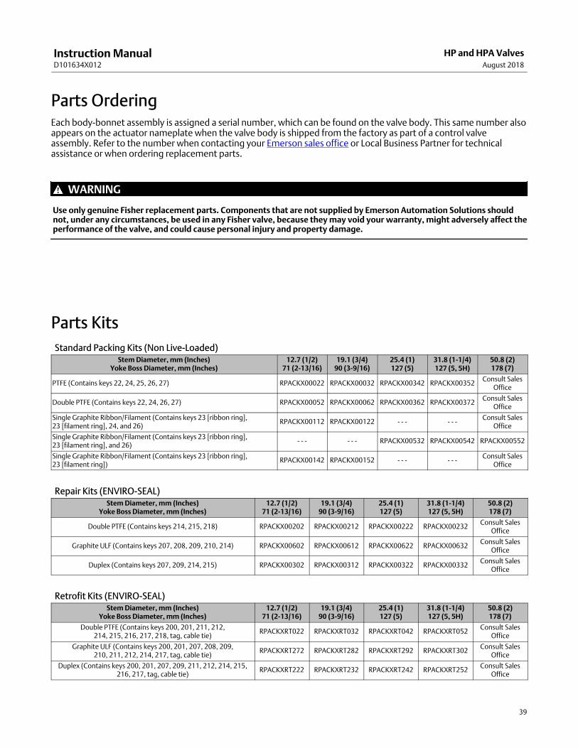
Instruction ManualD101634X012
HP and HPA ValvesAugust 2018
39
Parts OrderingEach body‐bonnet assembly is assigned a serial number, which can be found on the valve body. This same number alsoappears on the actuator nameplate when the valve body is shipped from the factory as part of a control valveassembly. Refer to the number when contacting your Emerson sales office or Local Business Partner for technicalassistance or when ordering replacement parts.
WARNING
Use only genuine Fisher replacement parts. Components that are not supplied by Emerson Automation Solutions shouldnot, under any circumstances, be used in any Fisher valve, because they may void your warranty, might adversely affect theperformance of the valve, and could cause personal injury and property damage.
Parts Kits
Standard Packing Kits (Non Live‐Loaded)Stem Diameter, mm (Inches)
Yoke Boss Diameter, mm (Inches)12.7 (1/2)
71 (2‐13/16)19.1 (3/4)
90 (3‐9/16)25.4 (1)127 (5)
31.8 (1-1/4)127 (5, 5H)
50.8 (2)178 (7)
PTFE (Contains keys 22, 24, 25, 26, 27) RPACKX00022 RPACKX00032 RPACKX00342 RPACKX00352Consult Sales
Office
Double PTFE (Contains keys 22, 24, 26, 27) RPACKX00052 RPACKX00062 RPACKX00362 RPACKX00372Consult Sales
Office
Single Graphite Ribbon/Filament (Contains keys 23 [ribbon ring], 23 [filament ring], 24, and 26)
RPACKX00112 RPACKX00122 - - - - - -Consult Sales
Office
Single Graphite Ribbon/Filament (Contains keys 23 [ribbon ring], 23 [filament ring], and 26)
- - - - - - RPACKX00532 RPACKX00542 RPACKX00552
Single Graphite Ribbon/Filament (Contains keys 23 [ribbon ring], 23 [filament ring])
RPACKX00142 RPACKX00152 - - - - - -Consult Sales
Office
Repair Kits (ENVIRO‐SEAL)Stem Diameter, mm (Inches)
Yoke Boss Diameter, mm (Inches)12.7 (1/2)
71 (2‐13/16)19.1 (3/4)
90 (3‐9/16)25.4 (1)127 (5)
31.8 (1‐1/4)127 (5, 5H)
50.8 (2)178 (7)
Double PTFE (Contains keys 214, 215, 218) RPACKX00202 RPACKX00212 RPACKX00222 RPACKX00232Consult Sales
Office
Graphite ULF (Contains keys 207, 208, 209, 210, 214) RPACKX00602 RPACKX00612 RPACKX00622 RPACKX00632Consult Sales
Office
Duplex (Contains keys 207, 209, 214, 215) RPACKX00302 RPACKX00312 RPACKX00322 RPACKX00332Consult Sales
Office
Retrofit Kits (ENVIRO‐SEAL)Stem Diameter, mm (Inches)
Yoke Boss Diameter, mm (Inches)12.7 (1/2)
71 (2‐13/16)19.1 (3/4)
90 (3‐9/16)25.4 (1)127 (5)
31.8 (1‐1/4)127 (5, 5H)
50.8 (2)178 (7)
Double PTFE (Contains keys 200, 201, 211, 212,214, 215, 216, 217, 218, tag, cable tie)
RPACKXRT022 RPACKXRT032 RPACKXRT042 RPACKXRT052Consult Sales
Office
Graphite ULF (Contains keys 200, 201, 207, 208, 209,210, 211, 212, 214, 217, tag, cable tie)
RPACKXRT272 RPACKXRT282 RPACKXRT292 RPACKXRT302Consult Sales
Office
Duplex (Contains keys 200, 201, 207, 209, 211, 212, 214, 215,216, 217, tag, cable tie)
RPACKXRT222 RPACKXRT232 RPACKXRT242 RPACKXRT252Consult Sales
Office

Instruction ManualD101634X012
HP and HPA ValvesAugust 2018
40
Gasket Set* (Includes Key 11 Bonnet Gasket and Key 12 Seat Ring Gasket)(1)
NPS 1 to NPS 6 HPD, HPT and NPS 1 to NPS 8 HPAD, HPAT
VALVE RATINGVALVE STYLE AND SIZE, NPS MATERIAL
HP Globe HPA Angle N06600/Graphite N07750/Graphite
CL1500Globe and Angle Valves
1 (std) 1 (std) 12B7100X012 12B7100X022
2 (std) 2 (std) and 3 (std) 12B7100X032 12B7100X042
2 (Cavitrol III,2‐Stage)
2 (Cavitrol III,2‐Stage)
12B7100X072 ‐ ‐ ‐
3 (std) 4 (std) 12B7100X052 12B7100X062
4 (std) 6 (std) 12B7100X082 ‐ ‐ ‐
6 (std) 8 (std) 12B7100X112 ‐ ‐ ‐
CL2500Globe and Angle Valves
1 (std) 1 (std) 12B7100X152 12B7100X122
2 (std) 2 (std) 12B7100X162 12B7100X132
2 (Cavitrol III,2‐Stage)
2 (Cavitrol III,2‐Stage)
12B7100X172 12B7100X142
1. Gaskets should always be replaced as sets, not separately.
Gasket Set* (Includes Key 11 Bonnet Gasket, Key 43 Cage Gasket and Key 12 Seat Ring Gasket)(1)
NPS 8 to NPS 12 HPD and HPT
VALVE RATING
VALVE STYLE AND SIZE, NPS MATERIAL
HP Globe HPA AngleBonnet Spiral
Wound GasketN06600/Graphite
Cage Spiral WoundGasket
N06600/Graphite
Seat Ring Flat SheetGakset
S31600/Graphite
CL900
8 (std) ‐ ‐ ‐ GG53667X012 GG53677X012 GG53849X012
10 (std)‐ ‐ ‐ GG53684X012 GG53685X012 GG53852X012
12 (std) ‐ ‐ ‐ GG53692X012 GG53693X012 GG53854X012
CL1500
8 (std) ‐ ‐ ‐ GG53678X012 GG53679X012 GG53849X012
10 (std) ‐ ‐ ‐ GG53686X012 GG53687X012 GG53852X012
12 (std) ‐ ‐ ‐ GG53694X012 GG53695X012 GG53854X012
CL2500
8 (std) ‐ ‐ ‐ GG53680X012 GG53681X012 GG53850X012
10 (std) ‐ ‐ ‐ GG53688X012 GG53689X012 GG53853X012
12 (std) ‐ ‐ ‐ GG53696X012 GG53697X012 GG53855X012
CL3200
8 (std) ‐ ‐ ‐ GG53682X012 GG53683X012 GG53850X012
10 (std) ‐ ‐ ‐ GG53690X012 GG53691X012 GG53853X012
12 (std)‐ ‐ ‐ GG53698X012 GG53699X012 GG53855X012
1. Gaskets should always be replaced as sets, not separately.
*Recommended spare parts
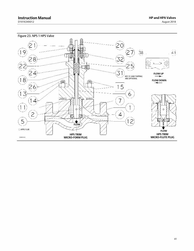
Instruction ManualD101634X012
HP and HPA ValvesAugust 2018
41
Figure 23. NPS 1 HPS Valve
FLOW
FLOW
FLOW UP
FLOW DOWN
� APPLY LUB
52B6054‐B
HPS TRIMMICRO‐FORM PLUG
HPS TRIMMICRO‐FLUTE PLUG
KEY 31 AND TAPPINGARE OPTIONAL
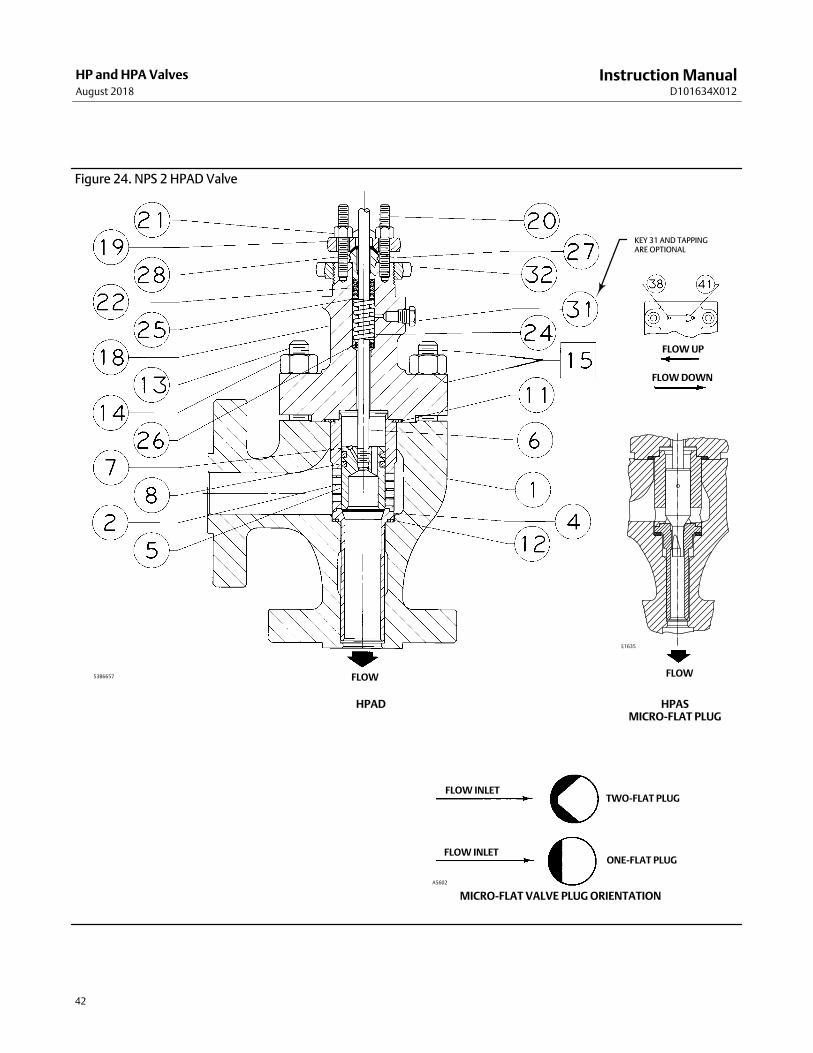
Instruction ManualD101634X012
HP and HPA ValvesAugust 2018
42
Figure 24. NPS 2 HPAD Valve
HPAD
FLOW
HPASMICRO‐FLAT PLUG
FLOW
FLOW UP
FLOW DOWN
53B6657
KEY 31 AND TAPPINGARE OPTIONAL
MICRO-FLAT VALVE PLUG ORIENTATION
A5602
FLOW INLET
FLOW INLET
TWO-FLAT PLUG
ONE-FLAT PLUG
E1635

Instruction ManualD101634X012
HP and HPA ValvesAugust 2018
43
Figure 25. NPS 2‐6 HPD Valve
FLOW UP
FLOW DOWN
HPD TRIM
FLOW
127 mm (5‐INCH) YOKE BOSS(GLOBE & ANGLE)
EXTENSION BONNET BAFFLE ASSEMBLY(NPS 2 ONLY) (GLOBE & ANGLE)
52B6045‐C
� APPLY LUB
KEY 31 AND TAPPINGARE OPTIONAL

Instruction ManualD101634X012
HP and HPA ValvesAugust 2018
44
Figure 26. NPS 2‐6 HP Valve ‐ Alternate Configurations
FLOW
HPT, HPAT TRIM(ALL SIZES)
FLOW
NPS 2‐3 HPS TRIMFLOW
HPS TRIMMICRO‐FORM PLUG
(NPS 2 ONLY)
FLOW
NPS 2 HPT TRIM2 STAGE CAVITROL III
FLOW
NPS 2 HPS TRIM3 STAGE CAVITROL III
FLOW
NPS 3‐6 HPT TRIM2 STAGE CAVITROL III
FLOW
NPS 3‐6 HPT TRIM3 STAGE CAVITROL III
FLOWUP
HPT, HPAT USINGPEEK ANTI‐EXTRUSION RINGS
FLOWDOWN
52B6045‐C
21B2120‐AA6137
VIEW A
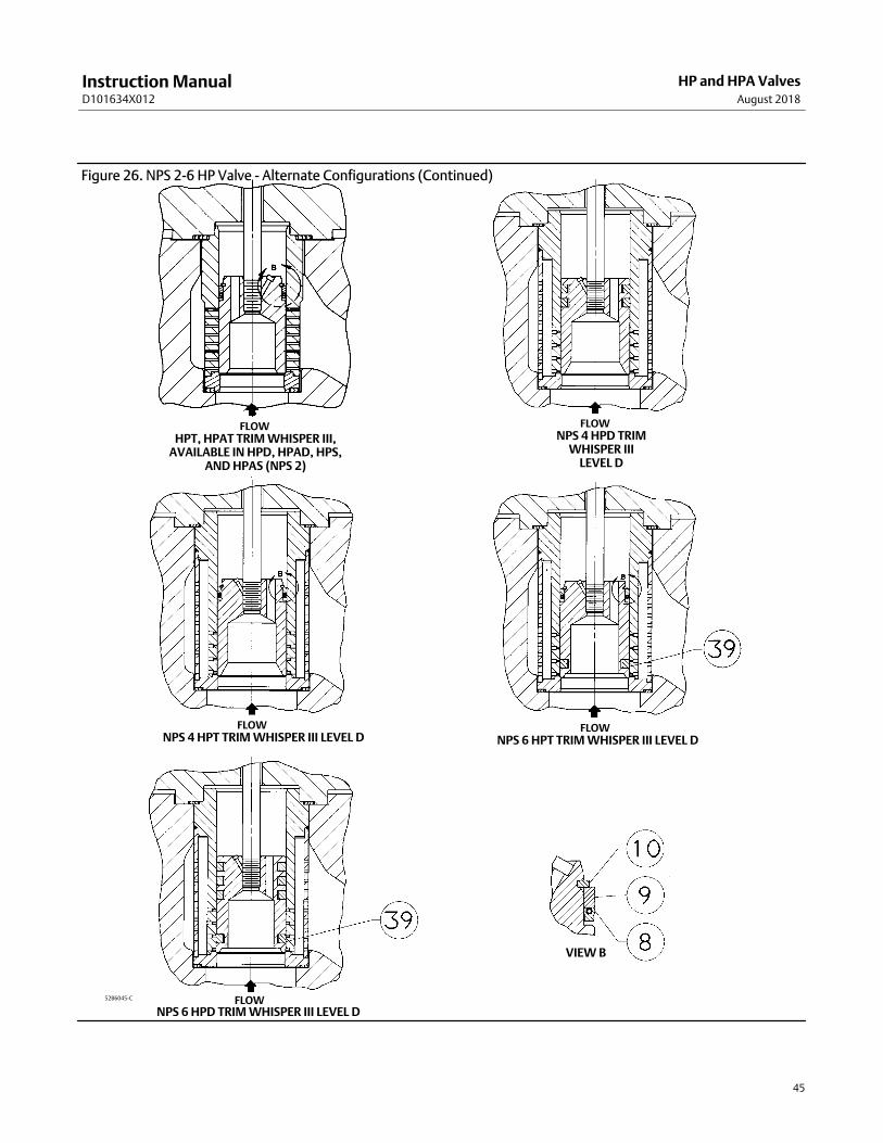
Instruction ManualD101634X012
HP and HPA ValvesAugust 2018
45
Figure 26. NPS 2‐6 HP Valve ‐ Alternate Configurations (Continued)
FLOWHPT, HPAT TRIM WHISPER III,
AVAILABLE IN HPD, HPAD, HPS,AND HPAS (NPS 2)
FLOWNPS 4 HPD TRIM
WHISPER IIILEVEL D
FLOWNPS 4 HPT TRIM WHISPER III LEVEL D
FLOWNPS 6 HPT TRIM WHISPER III LEVEL D
FLOWNPS 6 HPD TRIM WHISPER III LEVEL D
52B6045‐C
VIEW B
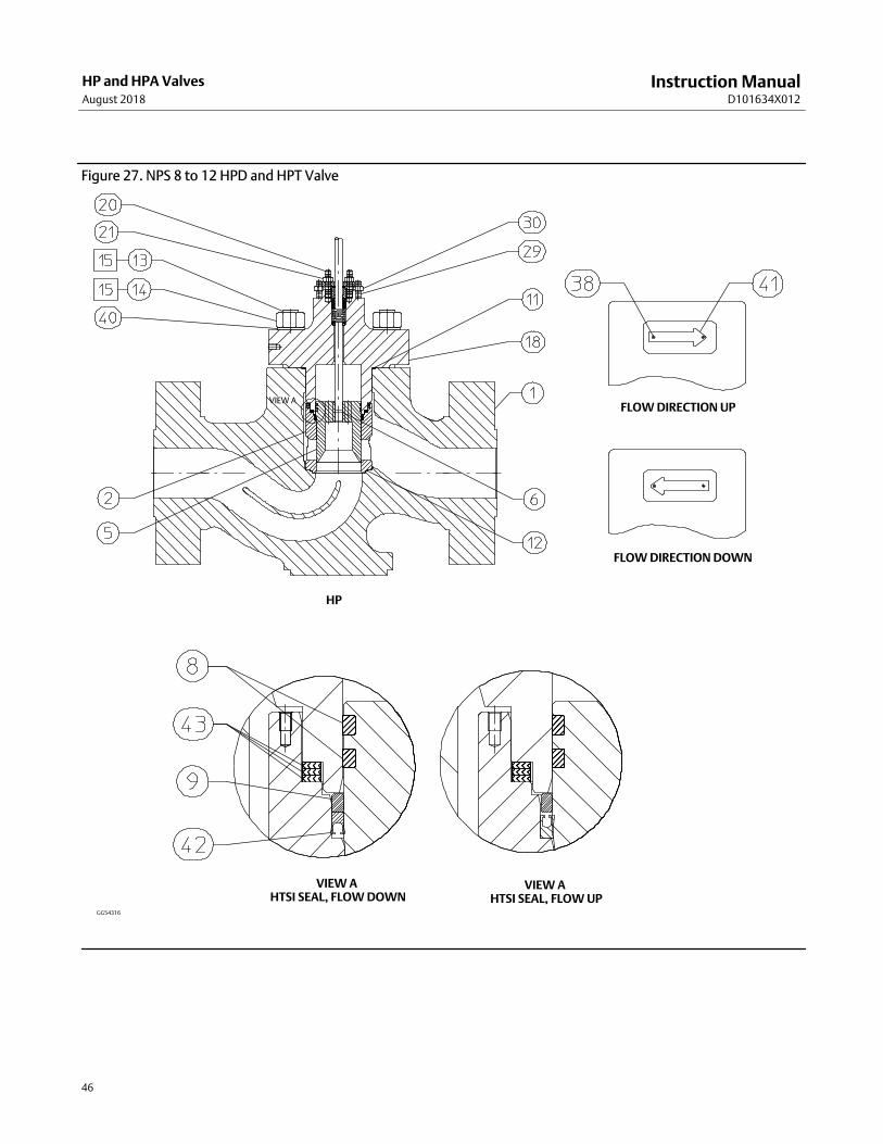
Instruction ManualD101634X012
HP and HPA ValvesAugust 2018
46
Figure 27. NPS 8 to 12 HPD and HPT Valve
VIEW A HTSI SEAL, FLOW DOWN
VIEW A HTSI SEAL, FLOW UP
FLOW DIRECTION UP
FLOW DIRECTION DOWN
HP
VIEW A
GG54316

Instruction ManualD101634X012
HP and HPA ValvesAugust 2018
47
Figure 28. NPS 8 to 12 HPD and HPT Valve - Alternate Configurations
VIEW ABORE SEAL, FLOW DOWN
VIEW ABORE SEAL, FLOW UP
WINDOW, LINEAR CAVITROL III, 2 STAGE
WHISPER III, D3 CAVITROL III, 3 STAGE
GG54316

Instruction ManualD101634X012
HP and HPA ValvesAugust 2018
48
Parts List
Numerous available combinations of valve parts make selection of
some parts difficult. When ordering valve parts, provide the valve
serial number with the order, permitting proper selection of
replacement parts to be made at the factory.
Note
Contact your Emerson sales office or Local Business Partner for Part
Ordering information.
Key Description
1 Valve Body
If you need a valve body as a replacement part, order by valve
size, serial number, and desired material.
2* Cage/Baffle Assy
3 Bonnet Spacer
4* Seat Ring
5* Valve Plug
6* Valve Stem
7* Pin
8* Seal Ring/Piston Ring
9* Back Up Ring
10* Retaining Ring (for NPS 6 and smaller HPT/HPAT only)
11* Bonnet Gasket
12* Seat Ring Gasket
13 Stud, Cont Thd
14 Hex Nut
15 Anti‐Seize Lubricant (8 lb [3.6 Kg] can)
16 Nameplate
17 Wire
18 Bonnet
If you need a bonnet as a replacement part, order by valve size
and stem diameter, serial number, and desired material.
19 Packing Flange
Key Description
20 Stud Bolt
21 Hex Nut
22* Packing Set
23* Packing Ring
24 Spring or Lantern Ring
25 Washer, Special
26* Packing Box Ring
27* Upper Wiper
28 Follower
29 Stud Bolt
30 Hex Nut
31 Pipe Plug (optional)
31 Lubricator (optional)
31 Lubricator/Isolating Valve (optional)
32 Yoke Locknut (optional)
36 Baffle
37 Retaining Ring
38 Drive Screw
39* Piston Ring
40 Washer
41 Flow Arrow
42* Soft Seal or Bore seal
43* Cage Gasket
44 Nameplate
63* Anti‐Extrusion Ring
C‐seal Trim (figure 14)2* Cage
4* Seat Ring
5* Valve Plug/Retainer
6* Valve Plug Stem, S20910
8* Piston Ring, graphite (2 req'd)
64* C‐seal, N07718
TSO Trim (figures 8, 9, and 10)2* Cage
4* Seat Ring
5* Plug/Stem Assembly
8* Seal Ring
63* Anti‐Extrusion Ring
9* Back Up Ring
10* Retaining Ring
*Recommended spare parts
Emerson Automation Solutions Marshalltown, Iowa 50158 USASorocaba, 18087 BrazilCernay, 68700 FranceDubai, United Arab EmiratesSingapore 128461 Singapore
www.Fisher.com
The contents of this publication are presented for informational purposes only, and while every effort has been made to ensure their accuracy, they are notto be construed as warranties or guarantees, express or implied, regarding the products or services described herein or their use or applicability. All sales aregoverned by our terms and conditions, which are available upon request. We reserve the right to modify or improve the designs or specifications of suchproducts at any time without notice.
� 1991, 2018 Fisher Controls International LLC. All rights reserved.
Fisher, Cavitrol, ENVIRO-SEAL, FIELDVUE, Whisper Trim, and WhisperFlo are marks owned by one of the companies in the Emerson Automation Solutionsbusiness unit of Emerson Electric Co. Emerson Automation Solutions, Emerson, and the Emerson logo are trademarks and service marks of Emerson ElectricCo. All other marks are the property of their respective owners.
Neither Emerson, Emerson Automation Solutions, nor any of their affiliated entities assumes responsibility for the selection, use or maintenanceof any product. Responsibility for proper selection, use, and maintenance of any product remains solely with the purchaser and end user.