d-subminiature - mouser electronics · 2004-10-08 · 4-1 4 call toll free: 1 (800) 323-9612...
TRANSCRIPT

D-SUBMINIATURED*KL Series HTD/HPD SeriesD*A Series Overmold KitsD*U Series T* SeriesBasic D Series Series 1 - High ReliabilitySeries 3 - High Reliability M24308 SeriesBackshells/Junctionshells/Hoods AccessoriesApplication Tooling

4-1
4
Call Toll Free: 1 (800) 323-9612
D-subminiature ConnectorsInformation
Introduction
The D-subminiature is one of the most popular styles of connectors in the I/O category. It is used in computer, telecom, datacom, medical, and test instrumentation applications as well as in the military and aerospace fields.
Types of D-subminiature connectors manufactured by Cinch
• Printed Circuit Board connectors:- Vertical connectors for panel mounting with Dip Solder PC tails.- Right-Angle connectors for board mounting with Dip Solder PC tails.
• Wire Termination connectors for cable assemblies or wire harnesses:- Crimp and Poke connectors.- Solder Cup connectors.- Insulation Displacement connectors IDCS to terminate discrete wire or flat cable.- Wire Wrap connectors.
How to read this section
• The information pages provide standard data common to all D-subminiature connectors. These include:
- D-subminiature contact arrangements - see page 4-5.- Panel mounting specifications/hardware - see page 4-6.- D-subminiature shell dimensions - see page 4-7.- D-subminiature and combo D layouts - see pages 4-5, 4-8 thru 4-10, and 4-56.- General Performance Specifications - see page 4-2.- PCB thickness chart - see page 4-8.
• D-subminiature pages are grouped by series. A series is a family of connectors with a similar performance level.Each series shares a set of features and specifications, from economical and commercial grade product to high-reliability and military connectors. Each series begins with a page outlining general features and specifications of connectors, followed by the pages on individual connectors with drawings or features specific to that connector. Drawings reflect clarifications of dimensions not called out in the information pages of thiscatalog. The features of each series can be found in the chart on page 4-4.
• Accessories including backshells, junction shells, and hoods as well as hardware can be found on pages 4-80 thru 4-99.
• Termination tooling for Cinch connectors can be found at the end of the D-subminiature section of thiscatalog on pages 4-100 thru 4-104.

4-2Call Toll Free: 1 (800) 323-9612
4
D-subminiature ConnectorsInformation
Introduction
General Information
• All connectors are intermateable with any Cinch D-subminiature of comparable pin count and density, or the D-sub connector of any other manufacturer complying dimensionally with MIL-C-24308.
• Solder terminations and boardlocks meet the requirements for solderability in accordance with MIL-STD-202, Method 208.
• DURABILITY- Mated connectors are subjected to cycles of insertions and withdrawals specified on the catalog
page. After the prescribed cycles the connectors will meet the Cinch requirements concerning insertion-withdrawal force, individual contact insertion-withdrawal force, and contact resistance.
• APPROVALS- Most Cinch connectors have UL recognition and CSA approval; however, the specific approvals are listed
on the individual catalog pages.
• CONTACTS
- Cinch connector contacts are generally offered in Gold Flash or 30µin. gold plating for commercial product,and 50µin. gold plating for M24308 Series Military D-subminiature connectors.
- Cinch connectors utilize economical stamped and formed contacts and/or screw machine contacts for enhanced performance.
- Standard density connectors utilize size 20 contacts.
- Cinch 1.5 Density Series connectors utilize size 22 contacts for greater density in a standard sizeD-subminiature outer shell.
• METAL SHELLS
- Commercial-grade steel shells are usually available in zinc plating with yellow chromate finish or tin plating.
- Tin-plated plugs have grounding indents.
- Military grade M24308 Series connector shells are generally steel or in certain cases non-magnetic brass withcadmium plating and yellow chromate finish.
- Insulator materials are glass-filled polyester, glass-filled nylon, and diallyl phthalate.
• The connectors are usually available in plugs and sockets in 9, 15, 25, 37, and 50 position sizes.

4-3 Call Toll Free: 1 (800) 323-9612
4
D-subminiature ConnectorsInformation
Introduction
Printed Circuit Board Connectors
• Cinch provides connectors in various footprints, contact diameters, and lengths in both vertical and right-angle PC mount styles with dip solder tails.
• Cinch PCB connectors have metal shells.
Connectors for Terminating Cable Wire
• Wire Wrap connectors are available in two tail lengths for two-wrap and three-wrap terminations. The contact is terminated by wrapping wire around it using a wire wrap gun. This connector is especially useful forprototyping since the wire can be unwrapped and rewrapped if necessary.
• Solder Cup connectors allow reliable long-term termination by soldering the wire directly into the connectorcontact. Cinch Solder Cups accommodate up to 20 AWG wire.
• Crimp and Poke connectors allow the wire to be terminated more economically than wire wrap or solder cup styles. Contacts are crimped and inserted into the connector. In our D*U Series, the contact is crimped around the conductor wire. In our D*A Series, the contact is crimped around the wire and the insulation. Crimp and Poke connectors can be selectively loaded to save labor and material cost.
• IDC connectors are an alternative to other types of wire termination connectors. IDC is much faster and veryreliable when all contacts are terminated and the volume is high. IDC utilizes mass termination of the cable wire.This can save considerable time and expense in the cable assembly process. The estimated time of terminating two ends of a 25-conductor discrete wire cable with 25-position D-subminiature connectors is about 5-1/2 to 6 minutes less per cable assembly using IDC connectors and Cinch Auto-Clinch termination tooling versus using Crimp and Poke connectors. This may vary considerably based on the operator, cable wire, and process.Cinch offers IDC connectors in two versions-for discrete wire or flat ribbon termination.

Feature Guide
The chart below contains Cinch D-subminiature product features and styles grouped by series.
Performance Level Economical Commercial High-Reliability Military
Series D*KL HPD/HTD D*A D*U T Basic D Series 1 Series 3 M24308
Termination TypeVertical PCB 4-12 4-26 4-42 4-50 •Right-Angle PCB 4-12 4-16 4-26 • 4-76
Crimp and Poke 4-16 4-20 4-26 • 4-72 4-76
Solder Cup 4-34 • 4-50 4-76
IDC •Wire Wrap •Insulator MaterialG-F Nylon • •G-F Polyester • • • •Diallyl Phthalate • • •Shell MaterialAll Plastic •Steel Shell • • • • • • • • •Shell PlatingTin-Lead Plating • • • • • • • •Zinc Plating-Y/C finish • • • • • •Cadmium Plating-Y/C finish •* • •Contact PlatingGold-Flash Plating • • • • • •30µin. Gold Plating • • • • • • • •50µin. Gold Plating •* • •Contact TypeStamped Contacts • • • • • •Machined Contacts • • • • •
Accessories information starts on page 4-80.Tooling information starts on page 4-100.
* Applies to Combination Layout Only.
4-4
4
Call Toll Free: 1 (800) 323-9612
D-subminiature ConnectorsInformation
Introduction
4-76
4-50
4-42
4-42
4-34

4-5 Call Toll Free: 1 (800) 323-9612
4
D-subminiature ConnectorsInformation
IntroductionContact Arrangements
NOTE: Mating face of plug is shown; socket is mirror image.
Standard Density Plug Inserts
1.5 Density Plug Inserts

4-6
4
D-subminiature ConnectorsInformation
Panel Mounting Specifications
Dimensions
Mounting MethodShell Front/ A B C D E F HSize Positions Rear Panel in mm in mm in mm in mm in mm in mm in mm
Front 0.98 24.89 0.49 12.45 0.87 22.10 0.44 11.18 0.51 12.95 0.26 6.60 0.08 2.03E 9
Rear 0.98 24.89 0.49 12.45 0.81 20.57 0.40 10.16 0.45 11.43 0.23 5.84 0.13 3.30Front 1.31 33.27 0.66 16.76 1.10 27.94 0.60 15.24 0.51 12.95 0.26 6.60 0.08 2.03
A 15Rear 1.31 33.27 0.66 16.76 1.13 28.70 0.57 14.48 0.45 11.43 0.23 5.84 0.13 3.30Front 1.85 46.99 0.93 23.62 1.74 44.20 0.87 22.10 0.51 12.95 0.26 6.60 0.08 2.03
B 25Rear 1.85 46.99 0.93 23.62 1.67 42.42 0.84 21.34 0.45 11.43 0.23 5.84 0.13 3.30Front 2.50 63.50 1.25 31.75 2.39 60.71 1.20 30.48 0.51 12.95 0.26 6.60 0.08 2.03
C 37Rear 2.50 63.50 1.25 31.75 2.33 59.18 1.16 29.46 0.45 11.43 0.23 5.84 0.13 3.30Front 2.41 61.21 1.20 30.48 2.30 58.42 1.15 29.21 0.62 15.75 0.31 6.60 0.08 2.03
D 50Rear 2.41 61.21 1.20 30.48 2.22 56.39 1.11 28.19 0.56 14.22 0.28 5.84 0.13 3.30
PANEL MOUNTING HARDWARE: Aids in alignment of plug and receptacle.
Float BushingReverse Float Bushing
Floating Dual Bushing
4-40 Clinch Nut
Rear panel mounting
Rear panel mountingFront and rear panel mounting
Front panel mounting
IntroductionShells and Mounts
Call Toll Free: 1 (800) 323-9612

Two Holes.120 + .005 (3.05 + 0.13) Dia.
4
4-7
Mating Side Termination Side
A +.015" B +.010" B1 +.005" C +.005" D +.010" D1 +.010" E +.010"Shell Connector (0.38mm) (0.25mm) (0.13 mm) (0.13mm) (0.25mm) (0.25mm) (0.25mm)Size Positions Type in mm in mm in mm in mm in mm in mm in mm
E 9 Plug 1.213 30.81 -- -- .666 16.90 0.984 24.99 -- -- .329 8.40 .494 12.55
Socket 1.213 30.81 .640 16.26 -- -- 0.984 24.99 .308 7.82 -- -- .494 12.55
A 15 Plug 1.541 39.14 -- --- .994 25.30 1.312 33.32 -- --- .329 8.40 .494 12.55
Socket 1.541 39.14 .968 24.59 -- -- 1.312 33.32 .308 7.82 -- -- .494 12.55
B 25 Plug 2.088 53.04 -- -- 1.534 39.00 1.852 47.04 -- -- .329 8.40 .494 12.55
Socket 2.088 53.04 1.508 38.30 -- -- 1.852 47.04 .308 7.82 -- -- .494 12.55
C 37 Plug 2.729 69.32 -- --- 2.182 55.40 2.500 63.50 -- --- .329 8.40 .494 12.55
Socket 2.729 69.32 2.156 54.76 -- -- 2.500 63.50 .308 7.82 -- --- .494 12.55
D 50 Plug 2.635 66.93 -- -- 2.079 52.80 2.406 61.11 -- -- .436 11.07 .605 15.37
Socket 2.635 66.93 2.062 52.34 -- -- 2.406 61.11 .420 10.67 -- -- .605 15.37
G +.010" H +.010" J +.010" K +.005" L +.010" M +.010"Shell Connector (0.25mm) (0.25mm) (0.25 mm) (0.25mm) (0.25mm) (0.25mm)Size Positions Type in mm in mm in mm in mm in mm in mm
E 9 Plug .759 19.28 .422 10.72 .030 0.76 .236 5.99 .045 1.14 .422 10.72
Socket .759 19.28 .422 10.72 .030 0.76 .243 6.17 .045 1.14 .429 10.92
A 15 Plug 1.083 27.51 .422 10.72 .030 0.76 .236 5.99 .045 1.14 .422 10.72
Socket 1.083 27.51 .422 10.72 .030 0.76 .253 6.17 .045 1.14 .429 10.92
B 25 Plug 1.625 41.27 .422 10.72 .039 0.99 .231 5.87 .060 1.52 .426 10.82
Socket 1.625 41.27 .422 10.72 .030 0.76 .243 6.17 .045 1.14 .429 10.92
C 37 Plug 2.272 57.71 .422 10.72 .039 0.99 .231 5.87 .060 1.52 .426 10.82
Socket 2.272 57.71 .422 10.72 .030 0.76 .243 6.17 .045 1.14 .429 10.92
D 50 Plug 2.178 55.32 .534 13.56 .039 0.99 .231 5.87 .060 1.52 .426 10.82
Socket 2.178 55.32 .534 13.56 .030 0.76 .243 6.17 .045 1.14 .429 10.92
B and D are outside dimensions for socket. D and B are inside dimensions for plug.
D-subminiature ConnectorsInformation
IntroductionShells and Mounts
Call Toll Free: 1 (800) 323-9612
4
4-8
D-subminiature ConnectorsInformation
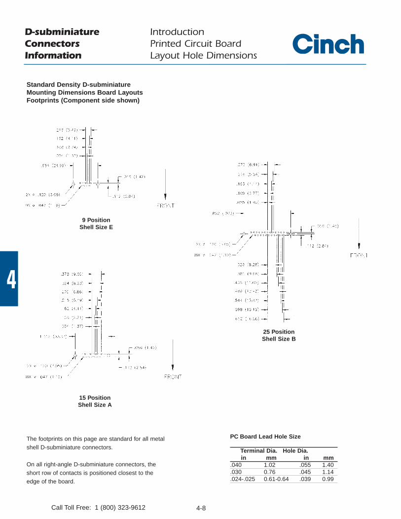
IntroductionPrinted Circuit BoardLayout Hole Dimensions
Standard Density D-subminiatureMounting Dimensions Board LayoutsFootprints (Component side shown)
9 PositionShell Size E
25 PositionShell Size B
15 PositionShell Size A
The footprints on this page are standard for all metalshell D-subminiature connectors.
On all right-angle D-subminiature connectors, the short row of contacts is positioned closest to the edge of the board.
PC Board Lead Hole Size
Terminal Dia. Hole Dia.in mm in mm
.040 1.02 .055 1.40
.030 0.76 .045 1.14
.024-.025 0.61-0.64 .039 0.99
Call Toll Free: 1 (800) 323-9612
15X
25X

4-9 Call Toll Free: 1 (800) 323-9612
4
D-subminiature ConnectorsInformation
IntroductionPrinted Circuit BoardLayout Hole Dimensions
50 PositionShell Size D
37 PositionShell Size C
Standard Density D-subminiatureMounting Dimensions Board LayoutsFootprints (Component side shown)
The footprints on this page are standard for all metalshell D-subminiature connectors.
On all right-angle D-subminiature connectors, the short row of contacts is positioned closest to the edge of the board.
PC Board Lead Hole Size
Terminal Dia. Hole Dia.in mm in mm
.040 1.02 .055 1.40
.030 0.76 .045 1.14
.024-.025 0.61-0.64 .039 0.99

4-10Call Toll Free: 1 (800) 323-9612
4
D-subminiature ConnectorsInformation
IntroductionPrinted Circuit BoardLayout Hole Dimensions
1.5 Density D-subminiatureRecommended PCB Layout forFootprint (Component side shown)
15 PositionShell Size E
62 PositionShell Size C
26 PositionShell Size A
44 PositionShell Size B
The footprints on this page are standard for all metalshell D-subminiature connectors.
On all right-angle D-subminiature connectors, the short row of contacts is positioned closest to the edge of the board.
PC Board Lead Hole Size
Terminal Dia. Hole Dia.in mm in mm
.040 1.02 .055 1.40
.030 0.76 .045 1.14
.024-.025 0.61-0.64 .039 0.99
)

4-12Call Toll Free: 1 (800) 323-9612
FEA
TURE
S
Offered in right-angle or vertical PCB mount versions.
Available with gold flash or 30µin. gold plating.
Metal Shell provides grounding and shielding capability.
Approvals:• UL Recognized: File E130965.• CSA Approved: File LR97981.
See pages 4-5 thru 4-10 for standard dimensions, contact arrangements, and panel mounting specifications.
MA
TERI
ALS
Insulator Material: Glass-filled polyester (black),UL 94V-O rated
Contact Material: Socket - Phosphor bronze (stamped)Plug - Brass (stamped)
Contact Plating: Gold flash or 30µin. gold in mating area and tin/lead on tails. All over nickel.
Metal Shell: Steel with tin plating (grounding indents on plug)
ENV
IRO
NM
ENTA
L Operating Temperature: -55°C to +125°CShock: 50G peak per MIL-STD-202, Method 213, Condition GVibration: 12 cycles in three perpendicular directions @
10-2000Hz, per MIL-STD-202, Method 204, Condition D
Moisture Resistance: 90-95% relative humidity @ 40°C for 96 hours per MIL-STD-202, Method 103
ELEC
TRIC
AL
Withstanding Voltage: Right Angle - minimum AC 1250V RMS @ sea level, Vertical - minimum AC1000V RMS @ sea level
Current Rating: 5 AmpsContact Resistance: 15 milliohms maximum
Insulation Resistance: 5000 megohms maximum (initial);1000 megohms (minimum) afterenvironmental testing
MEC
HA
NIC
AL
Individual Contact Insertion andSeparation Force (minimum/maximum): 0.7 oz./12 oz.
Durability: 500 mating cycles
D-subminiature Metal ShellRight-Angle and Vertical PCBD*KL Series

4-13 Call Toll Free: 1 (800) 323-9612
Economical D-subminiature Metal ShellRight-Angle PCBD*KL Series
Right-Angle Connectors
• 0.318" footprint.
• Available in 9, 15, and 25 position plugs and sockets.
• Offered with 4-40 threaded inserts for secure mounting to panels or with female screwlocks.
• Boardlocks to provide mechanical hold-down during wave soldering process.
• Materials:- Boardlock: Brass with tin plating.- Female Screwlock: Brass with nickel plating.
4-40 Threaded Inserts Female Screwlocks
Size Gold Flash 30µin. Gold Gold Flash 30µin. Gold
9 DEKL-9SAT-E DEKL-9SAT-E2 DEKL-9SAT-F DEKL-9SAT-F2
15 DAKL-15SAT-E DAKL-15SAT-E2 DAKL-15SAT-F DAKL-15SAT-F2
25 DBKL-25SAT-E DBKL-25SAT-E2 DBKL-25SAT-F DBKL-25SAT-F2
4-40 Threaded Inserts Female Screwlocks
Size Gold Flash 30µin. Gold Gold Flash 30µin. Gold
9 DEKL-9PATI-E DEKL-9PATI-E2 DEKL-9PATI-F DEKL-9PATI-F2
15 DAKL-15PATI-E DAKL-15PATI-E2 DAKL-15PATI-F DAKL-15PATI-F2
25 DBKL-25PATI-E DBKL-25PATI-E2 DBKL-25PATI-F DBKL-25PATI-F2
Right-Angle Sockets
Right-Angle Plugs
Ordering Information
4-14
4
Call Toll Free: 1 (800) 323-9612
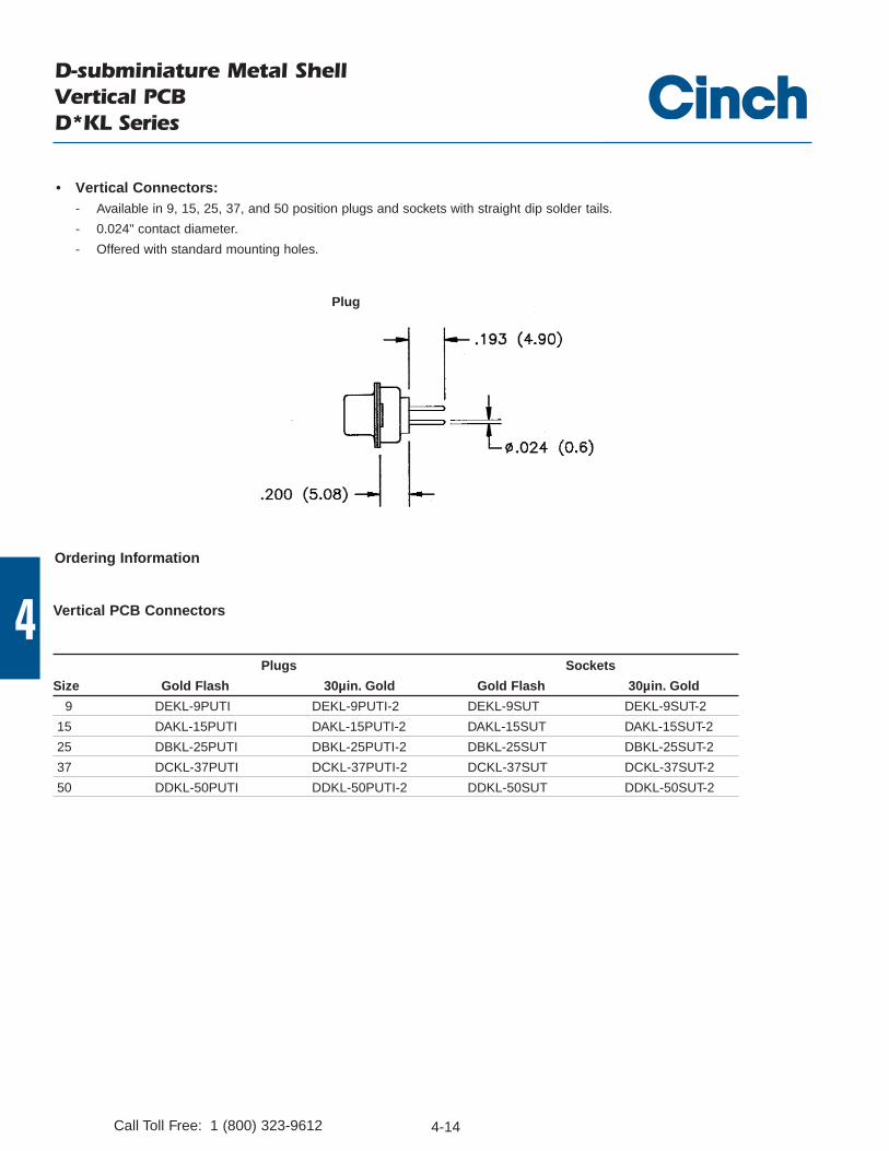
D-subminiature Metal ShellVertical PCBD*KL Series
Plugs Sockets
Size Gold Flash 30µin. Gold Gold Flash 30µin. Gold
9 DEKL-9PUTI DEKL-9PUTI-2 DEKL-9SUT DEKL-9SUT-2
15 DAKL-15PUTI DAKL-15PUTI-2 DAKL-15SUT DAKL-15SUT-2
25 DBKL-25PUTI DBKL-25PUTI-2 DBKL-25SUT DBKL-25SUT-2
37 DCKL-37PUTI DCKL-37PUTI-2 DCKL-37SUT DCKL-37SUT-2
50 DDKL-50PUTI DDKL-50PUTI-2 DDKL-50SUT DDKL-50SUT-2
Vertical PCB Connectors
Ordering Information
Plug
• Vertical Connectors:- Available in 9, 15, 25, 37, and 50 position plugs and sockets with straight dip solder tails.
- 0.024" contact diameter.
- Offered with standard mounting holes.
4-16Call Toll Free: 1 (800) 323-9612
FEA
TURE
S
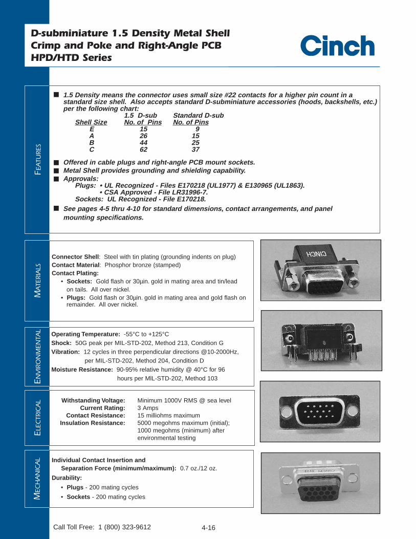
1.5 Density means the connector uses small size #22 contacts for a higher pin count in a standard size shell. Also accepts standard D-subminiature accessories (hoods, backshells, etc.) per the following chart:
1.5 D-sub Standard D-subShell Size No. of Pins No. of Pins
E 15 9A 26 15B 44 25C 62 37
Offered in cable plugs and right-angle PCB mount sockets. Metal Shell provides grounding and shielding capability. Approvals:
Plugs: • UL Recognized - Files E170218 (UL1977) & E130965 (UL1863).• CSA Approved - File LR31996-7.
Sockets: UL Recognized - File E170218. See pages 4-5 thru 4-10 for standard dimensions, contact arrangements, and panel
mounting specifications.
MA
TERI
ALS
Connector Shell: Steel with tin plating (grounding indents on plug)Contact Material: Phosphor bronze (stamped)Contact Plating:
• Sockets: Gold flash or 30µin. gold in mating area and tin/leadon tails. All over nickel.
• Plugs: Gold flash or 30µin. gold in mating area and gold flash onremainder. All over nickel.
ENV
IRO
NM
ENTA
L
Operating Temperature: -55°C to +125°CShock: 50G peak per MIL-STD-202, Method 213, Condition GVibration: 12 cycles in three perpendicular directions @10-2000Hz,
per MIL-STD-202, Method 204, Condition DMoisture Resistance: 90-95% relative humidity @ 40°C for 96
hours per MlL-STD-202, Method 103
ELEC
TRIC
AL Withstanding Voltage: Minimum 1000V RMS @ sea level
Current Rating: 3 AmpsContact Resistance: 15 milliohms maximum
Insulation Resistance: 5000 megohms maximum (initial);1000 megohms (minimum) after environmental testing
MEC
HA
NIC
AL Individual Contact Insertion and
Separation Force (minimum/maximum): 0.7 oz./12 oz.
Durability:
• Plugs - 200 mating cycles
• Sockets - 200 mating cycles
D-subminiature 1.5 Density Metal ShellCrimp and Poke and Right-Angle PCBHPD/HTD Series

4-17 Call Toll Free: 1 (800) 323-9612
D-subminiature 1.5 Density Metal ShellCrimp and Poke PlugsHTD Series
Connectors:• Offered with .120 mounting holes.
• Shells offered with tin plating and grounding indents.
• These connectors are designed to accommodate one repair cycle.
Contacts: (Not included with connectors, order separately)
• Available with gold-flash plating or 30µin. gold.
• Crimp and Poke versions are offered in reels of 15,000 or 300 contacts.
• Solder and Poke contacts are packed loose.
• Will accommodate 22-30 AWG wire.
• Order contacts separately. See page 4-18.
Termination Tooling:• Semi-automatic Stripper Crimper Tool for 15,000 reels: #HTD-518. See page 4-102.
• Crimp Contact Hand Tool for 300-piece reels: #HTD-266. See page 4-101.
• Semi-automatic Hand Crimping Tool for individual contact termination: #HTD-544. See page 4-101.
• Contact Insertion/Extraction Tool: Cinch #CIET-22-DF. See page 4-101.
Materials:• Insulator Material: Black UL 94 V-0 glass-filled nylon.
Ordering Information
HTD Series 1. 5 Density Crimp and Poke Plug Connectors
Size Shell Size Catalog Number15 E HTDE-15PTI-FO26 A HTDA-26PTI-FO44 B HTDB-44PTI-FO62 C HTDC-62PTI-FO

4-18
4
• Use with HTD Series 1.5 D-Sub Crimp and Poke connectors and overmold kits.
• All Crimp and Poke contacts are on right-hand feed reels.
Crimp and Poke Plug Contact
Solder and Poke Plug
HTD Series 1. 5 D-sub Male Crimp and Poke and Solder and Poke Contacts
Type of Crimp and Poke Crimp and Poke Solder and PokePacking 15,000 Reel 300 Reel LoosePlating Gold Flash 30µin. Gold Gold Flash 30µin. Gold Gold Flash 30µin. GoldPin HTD-CP-9-15000 HTD-CP-1-15000 HTD-CP-9-300 HTD-CP-1-300 HTD-SP-9-10 Not Available
Ordering Information
D-subminiature 1.5 Density Metal ShellCrimp and Poke Plugs HTD Series
Call Toll Free: 1 (800) 323-9612

4-19
4
D-subminiature 1.5 Density Metal ShellRight-Angle PCB Sockets HPD Series
• .350" footprint.
• Offered with fixed 4-40 threaded inserts for secure mounting to panels or with assembled female screwlocks.
• Boardlocks to maintain electrical continuity between shell and PC board ground and provide mechanical hold-down during wave soldering process.
• Available in standard configuration sockets, sizes 15, 26, 44, and 62 with black insulator.
• 15 position socket also available with royal blue insulator in Windows ‘95® configuration with Pin #9 recessed 0.050".
Materials:
• Insulator Material: Glass-filled polyester (standard configuration - black, -9R configuration - blue),UL 94V-0 rated.
• Boardlock: Brass with tin plating. • Female Screwlock: Brass with Nickel plating.
Dimensions
A B C DPositions +.015 (+0.038) +.010 (+0.25) +.010 (+0.25)
in mm in mm in mm in mm15 1.214 30.84 0.984 24.99 0.640 16.26 0.090 2.29 26 1.545 39.24 1.312 33.32 0.967 24.56 0.090 2.29 44 2.088 53.04 1.852 47.04 1.508 38.30 0.090 2.29 62 2.730 69.34 2.500 63.50 2.156 54.76 0.095 2.41
Shell 4-40 Threaded Inserts Female ScrewlocksSize Size Type Color Gold Flash 30µin. Gold Gold Flash 30µin. Gold15 E Standard Black HPDEB-15SAT-E HPDEB-15SAT-E2 HPDEB-15SAT-F HPDEB-15SAT-F226 A Standard Black HPDAB-26SAT-E HPDAB-26SAT-E2 HPDAB-26SAT-F HPDAB-26SAT-F244 B Standard Black HPDBB-44SAT-E HPDBB-44SAT-E2 HPDBB-44SAT-F HPDBB-44SAT-F262 C Standard Black HPDCB-62SAT-E HPDCB-62SAT-E2 HPDCB-62SAT-F HPDCB-62SAT-F215 E Windows ‘95® Blue HPDEB-15SAT-E-9R HPDEB-15SAT-E2-9R HPDEB-15SAT-F-9R HPDEB-15SATF2-9R
Windows '95 is a registered trademark of Microsoft.
Ordering Information
HPD Series 1.5 Density Right-Angle Socket Connectors
WITH #4-40 FEMALE SCREWLOCKS
(ASSEMBLED)
Call Toll Free: 1 (800) 323-9612

4-20Call Toll Free: 1 (800) 323-9612
FEA
TURE
S
Offered in 9, 15 , 25, 37, and 50 position plugs and sockets. Contacts:
- Available with gold flash or 30µin. gold plating.- Offered in 15,000 contact reel or 300 contact reel, or in loose-piece bags of 100 or 1000 each.- Accommodate 20-24 AWG wire or 26-30 AWG wire.- Not included with connector - order stamped contacts separately.
Approvals:- UL Recognized - Files E170218 (UL1977) and E130965 (UL1863).- CSA Approved - File LR31996.
See pages 4-5 thru 4-10 for standard dimensions, contact arrangements, and panel mounting specifications.
MA
TERI
ALS
Insulator Material: Glass-filled nylon (black), UL 94 V-O ratedConnector Shell: Steel with zinc plating and yellow chromate finish or tin
plating (plug has grounding indents)Contact Material:
• Plug - Brass (stamped)• Socket - Phosphor bronze (stamped)
Contact Plating: Gold flash or 30µin. gold in mating area and gold flash on the remainder. All over nickel.
4-40 Clinch Nut: Steel with cadmium plating and yellow chromate finishDual Float Bushing: Stainless steel, passivated
ENV
IRO
NM
ENTA
L Operating Temperature: -65°C to + 125°CShock: 50G peak per MIL-STD-202, Method 213, Condition GVibration: 12 cycles in three perpendicular directions @ 10-2000Hz, per
MIL-STD-202, Method 204, Condition DMoisture Resistance: 90-95% relative humidity @ 40°C for 96 hours per
MIL-STD-202, Method 103
ELEC
TRIC
AL Withstanding Voltage: Minimum 1000V RMS @ sea level
Current Rating: 5 AmpsContact Resistance: 2.7 milliohms maximum
Insulation Resistance: 5000 megohms maximum (initial);1000 megohms (minimum) after environmental testing
MEC
HA
NIC
AL
Individual Contact Insertion andSeparation Force (minimum/maximum): 0.7 oz./12 oz.
Durability: 500 mating cycles
D-subminiature Metal ShellCrimp and PokeD*A Series

4-21 Call Toll Free: 1 (800) 323-9612
D-subminiature Metal ShellCrimp and Poke Connectors D*A Series
• Offered with .120 mounting holes or 4-40 clinch nuts.
Termination Tools• Semi-Automatic Stripper Crimper Tool for 15K reels: #GSC-20-30. See page 4-102.
• Contact Insertion/Extraction Tool: #CIET-20-HDB. See page 4-101.
• Crimp Contact Hand Tool for 300-piece reels: #GHC-B (20-26 AWG wire) or Catalog #GHC-B1 (28-30 AWG wire). See page 4-101.
• Crimp Contact Hand Tool for loose piece contacts: #HTD-544. See page 4-101.
.453 (11.51) MAX.
Ordering Information
D*A Series Crimp and Poke Connectors - Plugs
Zinc-plated shell with yellow chromate finish Tin-plated shell with grounding indents
Positions Mounting Holes 4-40 Clinch Nuts Mounting Holes 4-40 Clinch Nuts
9 DEA-9P-FO DEAE-9P-FO DEA-9PTI-FO DEAE-9PTI-FO
15 DAA-15P-FO DAAE-15P-FO DAA-15PTI-FO DAAE-15PTI-FO
25 DBA-25P-FO DBAE-25P-FO DBA-25PTI-FO DBAE-25PTI-FO
37 DCA-37P-FO DCAE-37P-FO DCA-37PTI-FO DCAE-37PTI-FO
50 DDA-50P-FO DDAE-50P-FO DDA-50PTI-FO DDAE-50PTI-FO
D*A Series Crimp and Poke Connectors - Sockets
Zinc-plated shell with yellow chromate finish Tin-plated shell
Positions Mounting Holes 4-40 Clinch Nuts Mounting Holes 4-40 Clinch Nuts
9 DEA-9S-FO DEAE-9S-FO DEA-9ST-FO DEAE-9ST-FO
15 DAA-15S-FO DAAE-15S-FO DAA-15ST-FO DAAE-15ST-FO
25 DBA-25S-FO DBAE-25S-FO DBA-25ST-FO DBAE-25ST-FO
37 DCA-37S-FO DCAE-37S-FO DCA-37ST-FO DCAE-37ST-FO
50 DDA-50S-FO DDAE-50S-FO DDA-50ST-FO DDAE-50ST-FO
4-22
4
Call Toll Free: 1 (800) 323-9612
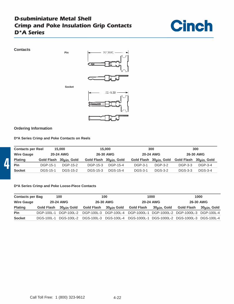
D*A Series Crimp and Poke Contacts on Reels
Contacts per Reel 15,000 15,000 300 300
Wire Gauge 20-24 AWG 26-30 AWG 20-24 AWG 26-30 AWG
Plating Gold Flash 30µin. Gold Gold Flash 30µin. Gold Gold Flash 30µin. Gold Gold Flash 30µin. Gold
Pin DGP-15-1 DGP-15-2 DGP-15-3 DGP-15-4 DGP-3-1 DGP-3-2 DGP-3-3 DGP-3-4
Socket DGS-15-1 DGS-15-2 DGS-15-3 DGS-15-4 DGS-3-1 DGS-3-2 DGS-3-3 DGS-3-4
D-subminiature Metal ShellCrimp and Poke Insulation Grip ContactsD*A Series
D*A Series Crimp and Poke Loose-Piece Contacts
Contacts per Bag 100 100 1000 1000
Wire Gauge 20-24 AWG 26-30 AWG 20-24 AWG 26-30 AWG
Plating Gold Flash 30µin Gold Gold Flash 30µin Gold Gold Flash 30µin. Gold Gold Flash 30µin. Gold
Pin DGP-100L-1 DGP-100L-2 DGP-100L-3 DGP-100L-4 DGP-1000L-1 DGP-1000L-2 DGP-1000L-3 DGP-100L-4
Socket DGS-100L-1 DGS-100L-2 DGS-100L-3 DGS-100L-4 DGS-1000L-1 DGS-1000L-2 DGS-1000L-3 DGS-100L-4
Contacts
Ordering Information
Socket
Pin

4-24Call Toll Free: 1 (800) 323-9612
D-subminiature Metal ShellOvermold KitsD*A and HTD Series
FEA
TURE
S
Cinch overmold kits enable you to overmold the connector of the cable assembly for less material and process cost (versus a metal backshell), improved appearance, and improved shielding of the connector to help meet RFI/EMI requirements.
An Overmold Kit catalog number consists of:- D*A or HTD Crimp and Poke connector.- Inside shielding cover.- Outside shielding cover.
You will also need to order the following:- Crimp and Poke stamped contacts must be ordered separately on page 4-22 for D*A
and page 4-18 for HTD connectors.- Ferrules are required, but must be ordered separately according to the size necessary to
accommodate the wire. See page 4-25.- Termination tooling is required to crimp the wires on the connector.- A hand tool and appropriate crimping die are required for crimping the ferrule.
All specifications on the connector portion of the overmold kit can be found on pages 4-16 thru4-17 for HPD 1.5 density and pages 4-20 thru 4-21 for D*A series.
MA
TERI
ALS
Shield Covers: Steel (stamped) with tin/lead finishFerrule: Brass
Overmold Shielding Kits
C D E F G HPositions in mm in mm in mm in mm Deg. in mm9 Plug 0.270 6.86 0.705 17.91 1.320 33.53 0.520 13.21 75° 0.440 11.189 Socket 0.285 7.24 0.705 17.91 1.320 33.53 0.520 13.21 75° 0.440 11.18
15 Plug 0.270 6.86 1.050 26.67 1.320 33.53 0.520 13.21 58° 0.440 11.1815 Socket 0.285 7.24 1.050 26.67 1.320 33.53 0.520 13.21 58° 0.440 11.1825 Plug 0.275 6.99 1.590 40.39 1.320 33.53 0.520 13.21 40° 0.440 11.1825 Socket 0.285 7.24 1.590 40.39 1.320 33.53 0.520 13.21 40° 0.440 11.1837 Plug 0.275 6.99 2.240 56.90 1.620 41.15 0.750 19.05 32° 0.520 13.2137 Socket 0.285 7.24 2.240 56.90 1.620 41.15 0.750 19.05 32° 0.520 13.21
Dimensions
4-25 Call Toll Free: 1 (800) 323-9612
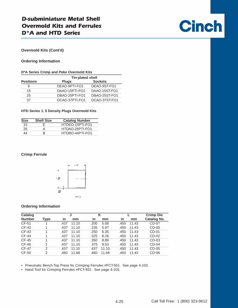
D-subminiature Metal ShellOvermold Kits and Ferrules D*A and HTD Series
• Pneumatic Bench Top Press for Crimping Ferrules #FCT-551. See page 4-103.• Hand Tool for Crimping Ferrules #FCT-552. See page 4-103.
Ordering Information
Catalog J K L Crimp DieNumber Type in mm in mm in mm Catalog No.CF-51 1 .437 11.10 .200 5.08 .450 11.43 CD-07CF-42 1 .437 11.10 .235 5.97 .450 11.43 CD-00CF-43 1 .437 11.10 .250 6.35 .450 11.43 CD-01CF-44 1 .437 11.10 .325 8.26 .450 11.43 CD-02CF-45 1 .437 11.10 .350 8.89 .450 11.43 CD-03CF-46 1 .437 11.10 375 9.53 .450 11.43 CD-04CF-47 2 .437 11.10 .437 11.10 .450 11.43 CD-05CF-50 2 .460 11.68 .460 11.68 .450 11.43 CD-06
Crimp Ferrule
HTD Series 1. 5 Density Plugs Overmold Kits
Overmold Kits (Cont’d)
Ordering Information
D*A Series Crimp and Poke Overmold Kits
Tin-plated shellPositions Plugs Sockets
9 DEAO-9PTI-FO1 DEAO-9ST-FO115 DAAO-15PTI-FO1 DAAO-15ST-FO125 DBAO-25PTI-FO1 DBAO-25ST-FO137 DCAO-37PTI-FO1 DCAO-37ST-FO1
Size Shell Size Catalog Number15 E HTDEO-15PTI-FO126 A HTDAO-26PTI-FO144 B HTDBO-44PTI-FO1

4-26Call Toll Free: 1 (800) 323-9612
FEA
TURE
S
Offered in 9, 15, 25, 37, and 50 position plugs and sockets (except right-angle PCB connectors-9 , 15, and 25 positions).
Available with gold flash or 30µin. gold plating. Offered with .120 mounting holes, optional 4-40 clinch nuts, or dual float bushings (except right-
angle PCB connectors-mounting holes only).
Approvals:
• UL Recognized - Files E170218 (UL1977) and E130965 (UL1863).• CSA Approved - File LR31996.
See pages 4-5 thru 4-10 for standard dimensions, contact arrangements, and panel mounting specifications.
MA
TERI
ALS
Insulator Material: Glass-filled nylon (black), UL 94 V-O rated
Connector Shell: Steel with zinc plating and yellow chromatefinish or tin plating (grounding indents on plug)
4-40 Clinch Nut: Steel with cadmium plating and yellowchromate finish
Dual Float Bushing: Stainless steel, passivated
ENV
IRO
NM
ENTA
L Operating Temperature: -65°C to + 125°CShock: 50G peak per MIL-STD-202, Method 213, Condition GVibration: 12 cycles in three perpendicular directions @
10-2000Hz, per MIL-STD-202, Method 204, Condition D
Moisture Resistance: 90-95% relative humidity @ 40°C for96 hours per MIL-STD-202, Method 103
ELEC
TRIC
AL
Withstanding Voltage: Minimum 1000V RMS @ sea level
Current Rating: 5 Amps
Contact Resistance: 2.7 milliohms maximum
Insulation Resistance: 5000 megohms maximum
(initial); 1000 megohms (minimum)
after environmental testing
MEC
HA
NIC
AL
Individual Contact Insertion and Separation Force (minimum/maximum): 0.7 oz./12 oz.
Durability: 500 mating cycles
D-subminiature Metal Shell Crimp and Poke, Right-Angle and Vertical PCBD*U Series

4-27
4
Call Toll Free: 1 (800) 323-9612
D-subminiature Metal Shell Crimp and Poke D*U Series
• Machined contacts supplied loose with connector or can be ordered separately. Use with 20-24 AWG wire.
• Stamped Contacts (order separately) for use when ordering connector with contacts not included (-FO option). Use with20-28 AWG wire.
- Available in 10K reel.- Order reels of stamped contacts separately.
Materials• Contact Material: Plug - Brass (stamped) or copper alloy (machined). Socket - Phosphor bronze (stamped) or copper
alloy (machined).
• Contact Plating:
- Stamped Plugs and Sockets: Gold flash or 30µin. gold and gold flash on the remainder. All over nickel.
- Machined Plugs and Sockets: Gold flash or 30µin. gold. All over nickel.
Termination Tooling
• Semi-Automatic Stripper Crimper for Stamped Contacts on 10K PC reels: #ESC-20-3. See page 4-102.
• Contact Insertion/Extraction: #CIET-20-HDB. See page 4-101.
• Loose Contact Crimp Tool:
Machined Contact - #M22520/2-01. See page 4-103.
For Positioner as required see page 4-103.
Stamped Contacts #BT-20-HC see page 4-101.
No positioner required.

4-28
4
Call Toll Free: 1 (800) 323-9612
D-subminiature Metal Shell Crimp and Poke D*U Series
Zinc-Plated Shell with Yellow Chromate FinishMounting Holes 4-40 Clinch Nuts Dual Float Bushings
Contacts Without Contacts Without Contacts Without Position Included Contacts Included Contacts Included Contacts
9 DEU-9S DEU-9S-FO DEUE-9S DEUE-9S-FO DEUY-9S DEUY-9S-FO 15 DAU-15S DAU-15S-FO DAUE-15S DAUE-15S-FO DAUY-15S DAUY-15S-FO25 DBU-25S DBU-25S-FO DBUE-25S DBUE-25S-FO DBUY-25S DBUY-25S-FO37 DCU-37S DCU-37S-FO DCUE-37S DCUE-37S-FO DCUY-37S DCUY-37S-FO 50 DDU-50S DDU-50S-FO DDUE-50S DDUE-50S-FO DDUY-50S DDUY-50S-FO
D*U Crimp and Poke Sockets
Tin-Plated Shell Mounting Holes 4-40 Clinch Nuts Dual Float Bushings
Contacts Without Contacts Without Contacts Without Position Included Contacts Included Contacts Included Contacts
9 DEU-9ST DEU-9ST-FO DEUE-9ST DEUE-9ST-FO DEUY-9ST DEUY-9ST-FO15 DAU-15ST DAU-15ST-FO DAUE-15ST DAUE-15ST-FO DAUY-15ST DAUY-15ST-FO25 DBU-25ST DBU-25ST-FO DBUE-25ST DBUE-25ST-FO DBUY-25ST DBUY-25ST-FO37 DCU-37ST DCU-37ST-FO DCUE-37ST DCUE-37ST-FO DCUY-37ST DCUY-37ST-FO50 DDU-50ST DDU-50ST-FO DDUE-50ST DDUE-50ST-FO DDUY-50ST DDUY-50ST-FO
Zinc-Plated Shell with Yellow Chromate FinishMounting Holes 4-40 Clinch Nuts Dual Float Bushings
Contacts Without Contacts Without Contacts Without Position Included Contacts Included Contacts Included Contacts
9 DEU-9P DEU-9P-FO DEUE-9-P DEUE-9P-FO DEUY-9P DEUY-9P-FO 15 DAU-15P DAU-15P-FO DAUE-15-P DAUE-15-P-FO DAUY-15P DAUY-15P-FO25 DBU-25P DBU-25P-FO DBUE-25-P DBUE-25P-FO DBUY-25P DBUY-25P-FO 37 DCU-37P DCU-37P-FO DCUE-37-P DCUE-37P-FO DCUY-37P DCUY-37P-FO50 DDU-50P DDU-50P-FO DDUE-50-P DDUE-50P-FO DDUY-50P DDUY-50P-FO
Tin-Plated Shell with Grounding IndentsMounting Holes 4-40 Clinch Nuts Dual Float Bushings
Contacts Without Contacts Without Contacts Without Position Included Contacts Included Contacts Included Contacts
9 DEU-9PTI DEU-9PTI-FO DEUE-9PTI DEUE-9PTI-FO DEUY-9PTI DEUY-9PTI-FO15 DAU-15PTI DAU-15PTI-FO DAUE-15PTI DAUE-15PTI-FO DAUY-15PTI DAUY-15PTI-FO25 DBU-25PTI DBU-25PTI-FO DBUE-25PTI DBUE-25PTI-FO DBUY-25PTI DBUY-25PTI-FO37 DCU-37PTI DCU-37PTI-FO DCUE-37PTI DCUE-37PTI-FO DCUY-37PTI DCUY-37PTI-FO50 DDU-50PTI DDU-50PTI-FO DDUE-50PTI DDUE-50PTI-FO DDUY-50PTI DDUY-50PTI-FO
D*U Crimp and Poke Plugs
Ordering Information

4-29
4
Call Toll Free: 1 (800) 323-9612
D-subminiature Metal ShellCrimp and Poke ContactsD*U Series
Gold Flash 30µin. GoldPin 030-1952-000 030-1952-030Socket 030-1953-000 030-1953-030
Ordering Information
D*U Series Stamped Contacts on 10K Reels
Dimensions
A B C Max.Wire
Description AWG in mm in mm in mmPin #20, 22, 24 .066 1.67 .045 1.14 .537 13.64Socket #20, 22, 24 .066 1.67 .045 1.14 .523 13.28
Plug Socket
Ordering Information
D*U Series Loose-Piece Machined Contacts
Plug Socket
Machined Contacts • 20-24 AWG Wire
Stamped Contacts • 20-28 AWG Wire
Gold Flash 30µin. GoldPin BCL-1964-20P D110238-034Socket BCL-1963-20S D110238-035

4-30
4
Call Toll Free: 1 (800) 323-9612
• .445" footprint.• .024" contact diameter.
Materials
• Contact Material: Socket - Copper alloy (machined), Plug - Brass (machined).
• Contact Plating: Gold flash or 30µin. gold. All over nickel.
• Mounting bracket: Black nylon. Can be removed if necessary.
D*U Right-Angle Sockets
Zinc-Plated Shell with Yellow Chromate Finish Tin-Plated Shell
Positions Gold Flash 30µin. Gold Gold Flash 30µin. Gold9 DEU-9SAD DEU-9SAD-30 DEU-9SADT DEU-9SADT-30
15 DAU-15SAD DAU-15SAD-30 DAU-15SADT DAU-15SADT-30
25 DBU-25SAD DBU-25SAD-30 DBU-25SADT DBU-25SADT-30
D*U Right-Angle Plugs
Zinc-Plated Shell with Yellow Chromate Finish Tin-Plated Shell with Grounding Indents
Positions Gold Flash 30µin. Gold Gold Flash 30µin. Gold9 DEU-9PAD DEU-9PAD-30 DEU-9PADTI DEU-9PADTI-30
15 DAU-15PAD DAU-15PAD-30 DAU-15PADTI DAU-15PADTI-3025 DBU-25PAD DBU-25PAD-30 DBU-25PADTI DBU-25PADTI-30
.375(9.50)
.010(0.25)Ref.
.040 (1.02)
.030 (0.76)
.026 (0.66)
.022 (0.56)
.117 (2.97)
.107 (2.72)Typ.
.657 (16.69)
.637 (16.18)
.164 (4.17)
.149 (3.78)
.453(11.51)
.437 11.10)
Ordering Information
D-subminiature Metal ShellRight-Angle Dip Solder PCBD*U Series

4-31
4
Call Toll Free: 1 (800) 323-9612
• .024" contact diameter.• Longer rear insulator provides integral standoff from PCB.
Materials
• Contact Material: Plug - Brass (machined), Socket - Copper alloy (machined).• Contact Plating: Gold flash or 30µin. gold. All over nickel.
D-subminiature Metal ShellVertical Dip Solder PCBD*U Series
.159 (4.04)
.129 (3.28)
.026 (066)
.022 (0.56)Typ.
.375(9.50)Max.
.514 (13.06)
.483 (12.27)
Vertical Plugs
Zinc-Plated Shell with Yellow Chromate FinishMounting Holes 4-40 Clinch Nuts Dual Float Bushings
Positions Gold Flash 30µin. Gold Gold Flash 30µin. Gold Gold Flash 30µin. Gold9 DEU-9PBF DEU-9PBF-30 DEUE-9PBF DEUE-9PBF-30 DEUY-9PBF DEUY-9PBF-30
15 DAU-15PBF DAU-15PBF-30 DAUE-15PBF DAUE-15PBF-30 DAUY-15PBF DAUY-15PBF-3025 DBU-25PBF DBU-25PBF-30 DBUE-25PBF DBUE-25PBF-30 DBUY-25PBF DBUY-25PBF-3037 DCU-37PBF DCU-37PBF-30 DCUE-37PBF DCUE-37PBF-30 DCUY-37PBF DCUY-37PBF-3050 DDU-50PBF DDU-50PBF-30 DDUE-50PBF DDUE-50PBF-30 DDUY-50PBF DDUY-50PBF-30
Tin-Plated Shell with Grounding IndentsMounting Holes 4-40 Clinch Nuts Dual Float Bushings
Positions Gold Flash 30µin. Gold Gold Flash 30µin. Gold Gold Flash 30µin. Gold9 DEU-9PBFTI DEU-9PBFTI-30 DEUE-9PBFTI DEUE-9PBFTI-30 DEUY-9PBFTI DEUY-9PBFTI-30
15 DAU-15PBFTI DAU-15PBFTI-30 DAUE-15PBFTI DAUE-15PBFTI-30 DAUY-15PBFTI DAUY-15PBFTI-3025 DBU-25PBFTI DBU-25PBFTI-30 DBUE-25PBFTI DBUE-25PBFTI-30 DBUY-25PBFTI DBUY-25PBFTI-3037 DCU-37PBFTI DCU-37PBFTI-30 DCUE-37PBFTI DCUE-37PBFTI-30 DCUY-37PBFTI DCUY-37PBFTI-3050 DDU-50PBFTI DDU-50PBFTI-30 DDUE-50PBFTI DDUE-50PBFTI-30 DDUY-50PBFTI DDUY-50PBFTI-30
Ordering Information

4-32
4
Call Toll Free: 1 (800) 323-9612
D-subminiature Metal ShellVertical Dip Solder PCBD*U Series
Vertical Sockets
Zinc-Plated Shell with Yellow Chromate FinishMounting Holes 4-40 Clinch Nuts Dual Float Bushings
Positions Gold Flash 30µin. Gold Gold Flash 30µin. Gold Gold Flash 30µin. Gold9 DEU-9SBF DEU-9SBF-30 DEUE-9SBF DEUE-9SBF-30 DEUY-9SBF DEUY-9SBF-30
15 DAU-15SBF DAU-15SBF-30 DAUE-15SBF DAUE-15SBF-30 DAUY-15SBF DAUY-15SBF-3025 DBU-25SBF DBU-25SBF-30 DBUE-25SBF DBUE-25SBF-30 DBUY-25SBF DBUY-25SBF-3037 DCU-37SBF DCU-37SBF-30 DCUE-37SBF DCUE-37SBF-30 DCUY-37SBF DCUY-37SBF-3050 DDU-50SBF DDU-50SBF-30 DDUE-50SBF DDUE-50SBF-30 DDUY-50SBF DDUY-50SBF-30
Tin-Plated ShellMounting Holes 4-40 Clinch Nuts Dual Float Bushings
Positions Gold Flash 30µin. Gold Gold Flash 30µin. Gold Gold Flash 30µin. Gold9 DEU-9SBFT DEU-9SBFT-30 DEUE-9SBFT DEUE-9SBFT-30 DEUY-9SBFT DEUY-9SBFT-30
15 DAU-15SBFT DAU-15SBFT-30 DAUE-15SBFT DAUE-15SBFT-30 DAUY-15SBFT DAUY-15SBFT-3025 DBU-25SBFT DBU-25SBFT-30 DBUE-25SBFT DBUE-25SBFT-30 DBUY-25SBFT DBUY-25SBFT-3037 DCU-37SBFT DCU-37SBFT-30 DCUE-37SBFT DCUE-37SBFT-30 DCUY-37SBFT DCUY-37SBFT-3050 DDU-50SBFT DDU-50SBFT-30 DDUE-50SBFT DDUE-50SBFT-30 DDUY-50SBFT DDUY-50SBFT-30
Ordering Information (Cont’d)

4-34Call Toll Free: 1 (800) 323-9612
FEA
TURE
S
Offered in 9, 15, 25, and 37 position plugs and sockets.
Available in Solder Cup and IDC (insulation displacement) terminations for discrete wire.
Offered with .120 mounting holes.
Approvals:
• UL Recognized - Files E170218 (UL1977) and E130965 (UL1863).• CSA Approved - File LR31996.
See pages 4-5 thru 4-10 for standard dimensions, contact arrangements, and panel mounting specifications.
MA
TERI
ALS
Insulator Material: Glass-filled polyester (black), UL 94 V-O ratedConnector Shell: Steel with zinc plating and yellow chromate finish or
tin plating (grounding indents on plug)Contact Material: Phosphor bronze (stamped)Contact Plating: Gold flash or 30µin. gold in mating area and gold
flash on the remainder. All over nickel.
ENV
IRO
NM
ENTA
L Operating Temperature: -65°C to + 125°C
Shock: 50G peak per MIL-STD-202, Method 213, Condition G
Vibration: 12 cycles in three perpendicular directions @ 10-2000Hz, per MIL-STD-202, Method 204, Condition D
Moisture Resistance: 90-95% relative humidity @ 40°C for 96 hours perMIL-STD-202, Method 103
ELEC
TRIC
AL
Withstanding Voltage: Minimum 1000V RMS @ sea level
Current Rating: 3 Amps
Contact Resistance: 2.7 milliohms maximum
Insulation Resistance: 5000 megohms maximum (initial);1000 megohms (minimum) after environmental testing
MEC
HA
NIC
AL
Individual Contact Insertion and Separation Force (minimum/maximum): 0.7 oz./12 oz.
Durability: 500 mating cycles
D-subminiature Metal Shell and All PlasticSolder Cup and IDCT* Series

4-35 Call Toll Free: 1 (800) 323-9612
• Solder channels between barriers permit single-pass soldering of each row without solder bridging.• Will accommodate up to 22 AWG wire.
D-subminiature Metal Shell Solder Cup for Discrete Cable WireT* Series
Ordering Information
Solder Cup Plugs
Zinc-Plated Shell Tin-Plated Shellwith Yellow Chromate Finish with Grounding Indents
Positions Gold Flash 30µin. Gold Gold Flash 30µin. Gold9 TE-9PS TE-9PS-30 TE-9PTIS TE-9PTIS-30
15 TA-15PS TA-15PS-30 TA-15PTIS TA-15PTIS-3025 TB-25PS TB-25PS-30 TB-25PTIS TB-25PTIS-3037 TC-37PS TC-37PS-30 TC-37PTIS TC-37PTIS-30
Solder Cup Sockets
Zinc-Plated Shell Tin-Plated Shellwith Yellow Chromate Finish
Positions Gold Flash 30µin. Gold Gold Flash 30µin. Gold9 TE-9SS TE-9SS-30 TE-9STS TE-9STS-30
15 TA-15SS TA-15SS-30 TA-15STS TA-15STS-3025 TB-25SS TB-25SS-30 TB-25STS TB-25STS-3037 TC-37SS TC-37SS-30 TC-37STS TC-37STS-30

4-36
4
Call Toll Free: 1 (800) 323-9612
Ordering Information
IDC Plugs
Zinc-Plated Shell Tin-Plated Shellwith Yellow Chromate Finish with Grounding Indents
Positions Gold Flash 30µin. Gold Gold Flash 30µin. Gold9 TE-9PSH TE-9PSH-30 TES-9PTI TES-9PTI-30
15 TA-15PSH TA-15PSH-30 TAS-15PTI TAS-15PTI-3025 TB-25PSH TB-25PSH-30 TBS-25PTI TBS-25PTI-3037 TC-37PSH TC-37PSH-30 TCS-37PTI TCS-37PTI-30
IDC Sockets
Zinc-Plated Shell Tin-Plated Shellwith Yellow Chromate Finish
Positions Gold Flash 30µin. Gold Gold Flash 30µin. Gold9 TE-9SSH TE-9SSH-30 TES-9ST TES-9ST-30
15 TA-15SSH TA-15SSH-30 TAS-15ST TAS-15ST-3025 TB-25SSH TB-25SSH-30 TBS-25ST TBS-25ST-3037 TC-37SSH TC-37SSH-30 TCS-37ST TCS-37ST-30
• Will accommodate 24-26 AWG solid or stranded PVC wire.
D-subminiature Metal ShellIDC for Discrete Cable Wire T* Series

4-37
4
Call Toll Free: 1 (800) 323-9612
D-subminiature Metal ShellIDC for Discrete Cable WireT* Series
• Optional strain relief covers for connectors when backshell is not required.
Positions Catalog No.9 SSD-WC9
15 SSD-WC1525 SSD-WC2537 SSD-WC37
• Auto-Clinch D Semi-Automatic Termination Tool #ACD-432: See page 4-100.• Certi-Clinch D Manual Termination Tool #SD-CCWN: For 24-26 AWG wire: See page 4-100.• Uni-Clinch D Single-Wire Hand Insertion Tool #SD-UC: See page 4-100.• Super D Manual Stay Band Tool #SD-MSBT: See page 4-100.
Ordering Information
• One-piece cover for 9 contact size. Order one per connector. Two-piece cover for other sizes. Order two per connector.• Cover fits both plug and socket.

4-38
4
Call Toll Free: 1 (800) 323-9612
• Auto-Clinch D Semi-Automatic Termination Tool #ACD-432: See page 4-100.• Certi-Clinch D Manual Termination Tool #SD-CC for 24-28 AWG wire: See page 4-100.• Uni-Clinch D Single-Wire Hand Insertion Tool #SD-UC: See page 4-100.• Super D Manual Stay Band Tool #SD-MSBT: See page 4-100.
D-subminiature All-Plastic IDC for Discrete Cable WireT* Series
Dimensions
A A B CP CS DPositions in mm in mm in mm in mm in mm in mm
9 1.209 30.71 1.309 33.25 .984 24.99 .668 16.96 .642 16.31 .592 15.0415 1.536 39.01 1.636 41.55 1.312 33.32 .995 25.28 .970 24.64 .918 23.3125 2.079 52.81 2.179 55.35 1.852 47.04 1.535 38.99 1.512 38.40 1.462 37.1337 2.724 69.19 2.824 71.73 2.500 63.50 2.183 55.45 2.158 54.81 2.114 53.70
• For use only with SDH Series Gray Backshell on pages 4-89 thru 4-90.• Offered in 9, 15, 25, and 37 position plugs and sockets.• Connector will accommodate 24-28 AWG wire.• Offered with plain flanges and .120 mounting holes, threaded bushings, latch blocks, or latch blocks and
threaded bushings.
Plug with Latching Blocks Socket with Latching Blocks

4-39
4
Call Toll Free: 1 (800) 323-9612
Plain FlangeMounting Holes 4-40 Threaded Bushings
Positions Gold Flash 30µin. Gold Gold Flash 30µin. Gold9 TE-9P TE-9P-30 TE-9PTB TE-9PTB-30
15 TA-15P TA-15P-30 TA-15PTB TA-15PTB-3025 TB-25P TB-25P-30 TB-25PTB TB-25PTB-3037 TC-37P TC-37P-30 TC-37PTB TC-37PTB-30
IDC All-Plastic Plugs
D-subminiature All-Plastic IDC for Discrete WireT* Series
Ordering Information
Flange with Latch BlockMounting Holes 4-40 Threaded Bushings
Positions Gold Flash 30µin. Gold Gold Flash 30µin. Gold9 TE-9PLB TE-9PLB-30 TE-9PLB-1 TE-9PLB-1-30
15 TA-15PLB TA-15PLB-30 TA-15PLB-1 TA-15PLB-1-3025 TB-25PLB TB-25PLB-30 TB-25PLB-1 TB-25PLB-1-3037 TC-37PLB TC-37PLB-30 TC-37PLB-1 TC-37PLB-1-30
Plain FlangeMounting Holes 4-40 Threaded Bushings
Positions Gold Flash 30µin. Gold Gold Flash 30µin. Gold9 TE-9S TE-9S-30 TE-9STB TE-9STB-30
15 TA-15S TA-15S-30 TA-15STB TA-15STB-3025 TB-25S TB-25S-30 TB-25STB TB-25STB-3037 TC-37S TC-37S-30 TC-37STB TC-37STB-30
IDC All-Plastic Sockets
Flange with Latch BlockMounting Holes 4-40 Threaded Bushings
Positions Gold Flash 30µin. Gold Gold Flash 30µin. Gold9 TE-9SLB TE-9SLB-30 TE-9SLB-1 TE-9SLB-1-30
15 TA-15SLB TA-15SLB-30 TA-15SLB-1 TA-15SLB-1-3025 TB-25SLB TB-25SLB-30 TB-25SLB-1 TB-25SLB-1-3037 TC-37SLB TC-37SLB-30 TC-37SLB-1 TC-37SLB-1-30

4-40Call Toll Free: 1 (800) 323-9612
FEA
TURE
S
Offered in Wire Wrap and Solder Cup styles for wire termination and vertical style for PCB mount.
Offered with .120 mounting holes, 4-40 clinch nuts, and dual float bushings.
Offered in 9, 15, 25, 37, and 50 position plugs and sockets.
Available with gold flash or 30µin. gold plating.
Approvals:• UL Recognized - Files E170218 (UL1977) and E130965 (UL1863).• CSA Approved - File LR31996.
See pages 4-5 thru 4-10 for standard dimensions, contact arrangements, and panel mounting specifications.
MA
TERI
ALS
Insulator Material: Glass-filled polyester (white), UL 94V-O rated
Connector Shell: Steel with zinc plating and yellow chromatefinish or tin plating (grounding indents on plug)
4-40 Clinch Nut: Steel with cadmium plating and yellow chromate finish
Dual Float Bushing: Stainless steel, passivated
ENV
IRO
NM
ENTA
L Operating Temperature: -65°C to + 125°C
Shock: 50G peak per MIL-STD-202, Method 213, Condition G
Vibration: 12 cycles in three perpendicular directions @ 10-2000Hz, per MIL-STD-202, Method 204, Condition D
Moisture Resistance: 90-95% relative humidity @ 40°C for 96 hours per MIL-STD-202, Method 103
ELEC
TRIC
AL
Withstanding Voltage: Minimum 1250V RMS @ sea level
Current Rating: 5 Amps
Contact Resistance: 2.7 milliohms maximum
Insulation Resistance: 5000 megohms maximum (initial);1000 megohms (minimum) after environmental testing
MEC
HA
NIC
AL
Individual Contact Insertion and Separation Force (minimum/maximum): 0.7 oz./12 oz.
Durability: 500 mating cycles
D-subminiature Metal ShellSolder Cup, Vertical PCB Mount, and Wire WrapBasic D Series

4-41
4
Call Toll Free: 1 (800) 323-9612
• Available with stamped or machined contacts.• Will accommodate up to 20 AWG wire.
Materials
• Contact Material: Copper Alloy
• Contact Plating:- Stamped contacts with gold flash or 30µin. gold in mating area, gold flash or tin/lead on remainder. All over nickel.- Screw machine contacts with gold flash or 30µin. gold. All over nickel.
D-subminiature Metal ShellSolder Cup Basic D Series
.312 (7.92)
.200 (5.08) REF.
Ordering Information
Stamped Contact with Gold Flash in Solder CupMounting Holes 4-40 Clinch Nuts Dual Float Bushings
Positions Gold Flash 30µin. Gold Gold Flash 30µin. Gold Gold Flash 30µin. Gold9 DE-9P DE-9P-30 DEE-9P DEE-9P-30 DEY-9P DEY-9P-30
15 DA-15P DA-15P-30 DAE-15P DAE-15P-30 DAY15P DAY-15P-3025 DB-25P DB-25P-30 DBE-25P DBE-25P-30 DBY-25P DBY-25P-3037 DC-37P DC-37P-30 DCE-37P DCE-37P-30 DCY-37P DCY-37P-3050 DD-50P DD-50P-30 DDE-50P DDE-50P-30 DDY-50P DDY-50P-30
Solder Cup Plugs
Stamped Contact with Tin/Lead in Solder CupMounting Holes 4-40 Clinch Nuts Dual Float Bushings
Positions Gold Flash 30µin. Gold Gold Flash 30µin. Gold Gold Flash 30µin. Gold9 DE-9P-II DE-9P-II-30 DEE-9P-II DEE-9P-II-30 DEY-9P-II DEY-9P-II-30
15 DA-15P-II DA-15P-II-30 DAE-15P-II DAE-15P-II-30 DAY-15P-II DAY-15-PII-3025 DB-25P-II DB-25P-II-30 DBE-25P-II DBE-25P-II-30 DBY-25P-II DBY-25-PII-3037 DC-37P-II DC-37P-II-30 DCE-37P-II DCE-37P-II-30 DCY-37-P-II DCY-37-PII-3050 DD-50P-II DD-50P-II-30 DDE-50P-II DDE-50P-II-30 DDY-50-P-II DDY-50-PII-30
Screw Machine ContactMounting Holes 4-40 Clinch Nuts Dual Float Bushings
Positions Gold Flash 30µin. Gold Gold Flash 30µin. Gold Gold Flash 30µin. Gold9 DE-9P-SM DE-9P-SM-30 DEE-9P-SM DEE-9P-SM-30 DEY-9P-SM DEY-9P-SM-30
15 DA-15P-SM DA-15P-SM-30 DAE-15P-SM DAE-15P-SM-30 DAY-15P-SM DAY-15P-SM-3025 DB-25P-SM DB-25P-SM-30 DBE-25P-SM DBE-25P-SM-30 DBY-25P-SM DBY-25P-SM-3037 DC-37P-SM DC-37P-SM-30 DCE-37P-SM DCE-37P-SM-30 DCY-37P-SM DCY-37P-SM-3050 DD-50P-SM DD-50P-SM-30 DDE-50P-SM DDE-50P-SM-30 DDY-50P-SM DDY-50P-SM-30
Zinc-Plated Shell with Yellow Chromate Finish

4-42
4
Call Toll Free: 1 (800) 323-9612
D-subminiature Metal ShellSolder Cup Basic D Series
Solder Cup Plugs (Cont’d)
Tin-Plated Shell with Grounding Indents
Stamped Contact with Gold Flash in Solder CupMounting Holes 4-40 Clinch Nuts Dual Float Bushings
Positions Gold Flash 30µin. Gold Gold Flash 30µin. Gold Gold Flash 30µin. Gold9 DE-9PTI DE-9PTI-30 DEE-9PTI DEE-9PTI-30 DEY-9PTI DEY-9PTI-30
15 DA-15PTI DA-15PTI-30 DAE-15PTI DAE-15PTI-30 DAY-15PTI DAY-15PTI-3025 DB-25PTI DB-25PTI-30 DBE-25PTI DBE-25PTI-30 DBY-25PTI DBY-25PTI-3037 DC-37PTI DC-37PTI-30 DCE-37PTI DCE-37PTI-30 DCY-37PTI DCY-37PTI-3050 DD-50PTI DD-50PTI-30 DDE-50PTI DDE-50PTI-30 DDY-50PTI DDY-50PTI-30
Stamped Contact with Tin/Lead in Solder CupMounting Holes 4-40 Clinch Nuts Dual Float Bushings
Positions Gold Flash 30µin. Gold Gold Flash 30µin. Gold Gold Flash 30µin. Gold9 DE-9PTI-II DE-9PTI-II-30 DEE-9PTI-II DEE-9PTI-II-30 DEY-9PTI-II DEY-9PTI-II-30
15 DA-15PTI-II DA-15PTI-II-30 DAE-15PTI-II DAE-15PTI-II-30 DAY-15PTI-II DAY-15PTI-II-3025 DB-25PTI-II DB-25PTI-II-30 DBE-25PTI-II DBE-25PTI-II-30 DBY-25PTI-II DBY-25PTI-II-3037 DC-37PTI-II DC-37PTI-II-30 DCE-37PTI-II DCE-37PTI-II-30 DCY-37PTI-II DCY-37PTI-II-3050 DD-50PTI-II DD-50PTI-II-30 DDE-50PTI-II DDE-50PTI-II-30 DDY-50PTI-II DDY-50PTI-II-30
Screw Machine ContactMounting Holes 4-40 Clinch Nuts Dual Float Bushings
Positions Gold Flash 30µin. Gold Gold Flash 30µin. Gold Gold Flash 30µin. Gold9 DE-9PTI-SM DE-9PTI-SM-30 DEE-9PTI-SM DEE-9PTI-SM-30 DEY-9PTI-SM DEY-9PTI-SM-30
15 DA-15PTI-SM DA-15PTI-SM-30 DAE-15PTI-SM DAE-15PTI-SM-30 DAY-15PTI-SM DAY-15PTI-SM-3025 DB-25PTI-SM DB-25PTI-SM-30 DBE-25PTI-SM DBE-25PTI-SM-30 DBY-25PTI-SM DBY-25PTI-SM-3037 DC-37PTI-SM DC-37PTI-SM-30 DCE-37PTI-SM DCE-37PTI-SM-30 DCY-37PTI-SM DCY-37PTI-SM-3050 DD-50PTI-SM DD-50PTI-SM-30 DDE-50PTI-SM DDE-50PTI-SM-30 DDY-50PTI-SM DDY-50PTI-SM-30
Ordering Information

4
Stamped Contact with Gold Flash in Solder CupMounting Holes 4-40 Clinch Nuts Dual Float Bushings
Positions Gold Flash 30µin. Gold Gold Flash 30µin. Gold Gold Flash 30µin. Gold9 DE-9S DE-9S-30 DEE-9S DEE-9S-30 DEY-9S DEY-9S-30
15 DA-15S DA-15S-30 DAE-15S DAE-15S-30 DAY-15S DAY-15S-3025 DB-25S DB-25S-30 DBE-25S DBE-25S-30 DBY-25S DBY-25S-3037 DC-37S DC-37S-30 DCE-37S DCE-37S-30 DCY-37S DCY-37S-3050 DD-50S DD-50S-30 DDE-50S DDE-50S-30 DDY-50S DDY-50S-30
Solder Cup Sockets
Stamped Contact Tin/Lead in Solder CupMounting Holes 4-40 Clinch Nuts Dual Float Bushings
Positions Gold Flash 30µin. Gold Gold Flash 30µin. Gold Gold Flash 30µin. Gold9 DE-9S-II DE-9S-II-30 DEE-9S-II DEE-9S-II-30 DEY-9S-II DEY-9S-II-30
15 DA-15S-II DA-15S-II-30 DAE-15S-II DAE-15S-II-30 DAY-15S-II DAY-15S-II-3025 DB-25S-II DB-25S-II-30 DBE-25S-II DBE-25S-II-30 DBY-25S-II DBY-25S-II-3037 DC-37S-II DC-37S-II-30 DCE-37S-II DCE-37S-II-30 DCY-37S-II DCY-37S-II-3050 DD-50S-II DD-50S-II-30 DDE-50S-II DDE-50S-II-30 DDY-50S-II DDY-50S-II-30
Screw Machine ContactMounting Holes 4-40 Clinch Nuts Dual Float Bushings
Positions Gold Flash 30µin. Gold Gold Flash 30µin. Gold Gold Flash 30µin. Gold9 DE-9S-SM DE-9S-SM-30 DEE-9S-SM DEE-9S-SM-30 DEY-9S-SM DEY-9S-SM-30
15 DA-15S-SM DA-15S-SM-30 DAE-15S-SM DAE-15S-SM-30 DAY-15S-SM DAY-15S-SM-3025 DB-25S-SM DB-25S-SM-30 DBE-25S-SM DBE-25S-SM-30 DBY-25S-SM DBY-25S-SM-3037 DC-37S-SM DC-37S-SM-30 DCE-37S-SM DCE-37S-SM-30 DCY-37S-SM DCY-37S-SM-3050 DD-50S-SM DD-50S-SM-30 DDE-50S-SM DDE-50S-SM-30 DDY-50S-SM DDY-50S-SM-30
Tin-Plated Shell
Zinc-Plated Shell with Yellow Chromate Finish
Stamped Contact with Gold Flash in Solder CupMounting Holes 4-40 Clinch Nuts Dual Float Bushings
Positions Gold Flash 30µin. Gold Gold Flash 30µin. Gold Gold Flash 30µin. Gold9 DE-9ST DE-9ST-30 DEE-9ST DEE-9ST-30 DEY-9ST DEY-9ST-30
15 DA-15ST DA-15ST-30 DAE-15ST DAE-15ST-30 DAY-15ST DAY-15ST-3025 DB-25ST DB-25ST-30 DBE-25ST DBE-25ST-30 DBY-25ST DBY-25ST-3037 DC-37ST DC-37ST-30 DCE-37ST DCE-37ST-30 DCY-37ST DCY-37ST-3050 DD-50ST DD-50ST-30 DDE-50ST DDE-50ST-30 DDY-50ST DDY-50ST-30
Stamped Contact with Tin/Lead in Solder CupMounting Holes 4-40 Clinch Nuts Dual Float Bushings
Positions Gold Flash 30µin. Gold Gold Flash 30µin. Gold Gold Flash 30µin. Gold9 DE-9ST-II DE-9ST-II-30 DEE-9ST-II DEE-9ST-II-30 DEY-9ST-II DEY-9ST-II-30
15 DA-15ST-II DA-15ST-II-30 DAE-15ST-II DAE-15ST-II-30 DAY-15ST-II DAY-15ST-II-3025 DB-25ST-II DB-25ST-II-30 DBE-25ST-II DBE-25ST-II-30 DBY-25ST-II DBY-25ST-II-3037 DC-37ST-II DC-37ST-II-30 DCE-37ST-II DCE-37ST-II-30 DCY-37ST-II DCY-37ST-II-3050 DD-50ST-II DD-50ST-II-30 DDE-50ST-II DDE-50ST-II-30 DDY-50ST-II DDY-50ST-II-30
Screw Machine ContactMounting Holes 4-40 Clinch Nuts Dual Float Bushings
Positions Gold Flash 30µin. Gold Gold Flash 30µin. Gold Gold Flash 30µin. Gold9 DE-9ST-SM DE-9ST-SM-30 DEE-9ST-SM DEE-9ST-SM-30 DEY-9ST-SM DEY-9ST-SM-30
15 DA-15ST-SM DA-15ST-SM-30 DAE-15ST-SM DAE-15ST-SM-30 DAY-15ST-SM DAY-15ST-SM-3025 DB-25ST-SM DB-25ST-SM-30 DBE-25ST-SM DBE-25ST-SM-30 DBY-25ST-SM DBY-25ST-SM-3037 DC-37ST-SM DC-37ST-SM-30 DCE-37ST-SM DCE-37ST-SM-30 DCY-37ST-SM DCY-37ST-SM-3050 DD-50ST-SM DD-50ST-SM-30 DDE-50ST-SM DDE-50ST-SM-30 DDY-50ST-SM DDY-50ST-SM-30
D-subminiature Metal ShellSolder Cup Basic D Series
Ordering Information
4-43 Call Toll Free: 1 (800) 323-9612

4-44
4
Call Toll Free: 1 (800) 323-9612
• .040" contact diameter.• Short rear insulator provides low profile on PCB.• Offered with .120 mounting holes, dual float bushings, or optional 4-40 clinch nuts.
Materials
• Contact Material: Socket - Phosphor bronze (machined), Plug - Brass (machined).• Contact Plating: Gold flash or 30µin. gold over nickel.
D-subminiature Metal ShellVertical Dip Solder PCB Basic D Series
.130 (3.30)
.104 (2.64)
.042 (1.07)
.038 (0.97)
.200 (5.08) REF.
Ordering Information
Vertical PCB Plugs
Zinc-Plated Shell with Yellow Chromate FinishMounting Holes 4-40 Clinch Nuts Dual Float Bushings
Positions Gold Flash 30µin. Gold Gold Flash 30µin. Gold Gold Flash 30µin. Gold9 DE-9PV DE-9PV-30 DEE-9PV DEE-9PV-30 DEY-9PV DEY-9PV-30
15 DA-15PV DA-15PV-30 DAE-15PV DAE-15PV-30 DAY-15PV DAY-15PV-3025 DB-25PV DB-25PV-30 DBE-25PV DBE-25PV-30 DBY-25PV DBY-25PV-3037 DC-37PV DC-37PV-30 DCE-37PV DCE-37PV-30 DCY-37PV DCY-37PV-3050 DD-50PV DD-50PV-30 DDE-50PV DDE-50PV-30 DCY-50PV DDY-50PV-30
Tin-Plated Shell with Grounding IndentsMounting Holes 4-40 Clinch Nuts Dual Float Bushings
Positions Gold Flash 30µin. Gold Gold Flash 30µin. Gold Gold Flash 30µin. Gold9 DE-9PVTI DE-9PVTI-30 DEE-9PVTI DEE-9PVTI-30 DEY-9PVTI DEY-9PVTI-30
15 DA-15PVTI DA-15PVTI-30 DAE-15PVTI DAE-15PVTI-30 DAY-15PVTI DAY-15PVTI-3025 DB-25PVTI DB-25PVTI-30 DBE-25PVTI DBE-25PVTI-30 DBY-25PVTI DBY-25PVTI-3037 DC-37PVTI DC-37PVTI-30 DCE-37PVTI DCE-37PVTI-30 DCY-37PVTI DCY-37PVTI-3050 DD-50PVTI DD-50PVTI-30 DDE-50PVTI DDE-50PVTI-30 DCY-50PVTI DDY-50PVTI-30
Vertical PCB Sockets
Zinc-Plated Shell with Yellow Chromate FinishMounting Holes 4-40 Clinch Nuts Dual Float Bushings
Positions Gold Flash 30µin. Gold Gold Flash 30µin. Gold Gold Flash 30µin. Gold9 DE-9SV DE-9SV-30 DEE-9SV DEE-9SV-30 DEY-9SV DEY-9SV-30
15 DA-15SV DA-15SV-30 DAE-15SV DAE-15SV-30 DAY-15SV DAY-15SV-3025 DB-25SV DB-25SV-30 DBE-25SV DBE-25SV-30 DBY-25SV DBY-25SV-3037 DC-37SV DC-37SV-30 DCE-37SV DCE-37SV-30 DCY-37SV DCY-37SV-3050 DD-50SV DD-50SV-30 DDE-50SV DDE-50SV-30 DCY-50SV DDY-50SV-30
Tin-Plated ShellMounting Holes 4-40 Clinch Nuts Dual Float Bushings
Positions Gold Flash 30µin. Gold Gold Flash 30µin. Gold Gold Flash 30µin. Gold9 DE-9SVT DE-9SVT-30 DEE-9SVT DEE-9SVT-30 DEY-9SVT DEY-9SVT-30
15 DA-15SVT DA-15SVT-30 DAE-15SVT DAE-15SVT-30 DAY-15SVT DAY-15SVT-3025 DB-25SVT DB-25SVT-30 DBE-25SVT DBE-25SVT-30 DBY-25SVT DBY-25SVT-3037 DC-37SVT DC-37SVT-30 DCE-37SVT DCE-37SVT-30 DCY-37SVT DCY-37SVT-3050 DD-50SVT DD-50SVT-30 DDE-50SVT DDE-50SVT-30 DDY-50SVT DDY-50SVT-30
4-45
4
Call Toll Free: 1 (800) 323-9612
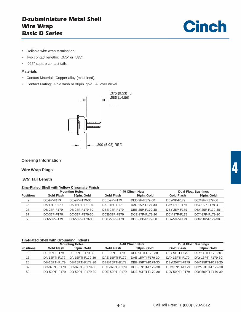
• Reliable wire wrap termination.
• Two contact lengths: .375" or .585".
• .025" square contact tails.
Materials
• Contact Material: Copper alloy (machined).
• Contact Plating: Gold flash or 30µin. gold. All over nickel.
D-subminiature Metal ShellWire WrapBasic D Series
.375 (9.53)
.585 (14.86)or
.200 (5.08) REF.
Ordering Information
Wire Wrap Plugs
.375" Tail Length
Zinc-Plated Shell with Yellow Chromate FinishMounting Holes 4-40 Clinch Nuts Dual Float Bushings
Positions Gold Flash 30µin. Gold Gold Flash 30µin. Gold Gold Flash 30µin. Gold
9 DE-9P-F179 DE-9P-F179-30 DEE-9P-F179 DEE-9P-F179-30 DEY-9P-F179 DEY-9P-F179-30
15 DA-15P-F179 DA-15P-F179-30 DAE-15P-F179 DAE-15P-F179-30 DAY-15P-F179 DAY-15P-F179-30
25 DB-25P-F179 DB-25P-F179-30 DBE-25P-F179 DBE-25P-F179-30 DBY-25P-F179 DBY-25P-F179-30
37 DC-37P-F179 DC-37P-F179-30 DCE-37P-F179 DCE-37P-F179-30 DCY-37P-F179 DCY-37P-F179-30
50 DD-50P-F179 DD-50P-F179-30 DDE-50P-F179 DDE-50P-F179-30 DDY-50P-F179 DDY-50P-F179-30
Tin-Plated Shell with Grounding IndentsMounting Holes 4-40 Clinch Nuts Dual Float Bushings
Positions Gold Flash 30µin. Gold Gold Flash 30µin. Gold Gold Flash 30µin. Gold
9 DE-9PTI-F179 DE-9PTI-F179-30 DEE-9PTI-F179 DEE-9PTI-F179-30 DEY-9PTI-F179 DEY-9PTI-F179-30
15 DA-15PTI-F179 DA-15PTI-F179-30 DAE-15PTI-F179 DAE-15PTI-F179-30 DAY-15PTI-F179 DAY-15PTI-F179-30
25 DB-25PTI-F179 DB-25PTI-F179-30 DBE-25PTI-F179 DBE-25PTI-F179-30 DBY-25PTI-F179 DBY-25PTI-F179-30
37 DC-37PTI-F179 DC-37PTI-F179-30 DCE-37PTI-F179 DCE-37PTI-F179-30 DCY-37PTI-F179 DCY-37PTI-F179-30
50 DD-50PTI-F179 DD-50PTI-F179-30 DDE-50PTI-F179 DDE-50PTI-F179-30 DDY-50PTI-F179 DDY-50PTI-F179-30

4-46
4
Call Toll Free: 1 (800) 323-9612
.585" Tail Length
Zinc-Plated Shell with Yellow Chromate FinishMounting Holes 4-40 Clinch Nuts Dual Float Bushings
Positions Gold Flash 30µin. Gold Gold Flash 30µin. Gold Gold Flash 30µin. Gold
9 DE-9P-F179C DE-9P-F179C-30 DEE-9P-F179C DEE-9PF-179C-30 DEY-9P-F179C DEY-9P-F179C-30
15 DA-15P-F179C DA-15P-F179C-30 DAE-15P-F179C DAE-15PF-179C-30 DAY-15P-F179C DAY-15P-F179C-30
25 DB-25P-F179C DB-25P-F179C-30 DBE-25P-F179C DBE-25PF-179C-30 DBY-25P-F179C DBY-25P-F179C-30
37 DC-37P-F179C DC-37P-F179C-30 DCE-37P-F179C DCE-37PF-179C-30 DCY-37P-F179C DCY-37P-F179C-30
50 DD-50P-F179C DD-50P-F179C-30 DDE-50P-F179C DDE-50PF-179C-30 DDY-50P-F179C DDY-50P-F179C-30
Tin-Plated Shell with Grounding IndentsMounting Holes 4-40 Clinch Nuts Dual Float Bushings
Positions Gold Flash 30µin. Gold Gold Flash 30µin. Gold Gold Flash 30µin. Gold
9 DE-9PTI-F179C DE-9PTI-F179C-30 DEE-9PTI-F179C DEE-9PTI-F179C-30 DEY-9PTI-F179C DEY-9PTI-F179C-30
15 DA-15PTI-F179C DA-15PTI-F179C-30 DAE-15PTI-F179C DAE-15PTI-F179C-30 DAY-15PTI-F179C DAY-15PTI-F179C-30
25 DB-25PTI-F179C DB-25PTI-F179C-30 DBE-25PTI-F179C DBE-25PTI-F179C-30 DBY-25PTI-F179C DBY-25PTI-F179C-30
37 DC-37PTI-F179C DC-37PTI-F179C-30 DCE-37PTI-F179C DCE-37PTI-F179C-30 DCY-37PTI-F179C DCY-37PTI-F179C-30
50 DD-50PTI-F179C DD-50PTI-F179C-30 DDE-50PTI-F179C DDE-50PTI-F179C-30 DDY-50PTI-F179C DDY-50PTI-F179C-30
Wire Wrap Plugs (Cont’d)
D-subminiature Metal ShellWire WrapBasic D Series
Ordering Information

4-47
4
Call Toll Free: 1 (800) 323-9612
Wire Wrap Sockets
.375" Tail Length
Zinc-Plated Shell with Yellow Chromate FinishMounting Holes 4-40 Clinch Nuts Dual Float Bushings
Positions Gold Flash 30µin. Gold Gold Flash 30µin. Gold Gold Flash 30µin. Gold
9 DE-9S-F179 DE-9S-F179-30 DEE-9S-F179 DEE-9S-F179-30 DEY-9S-F179 DEY-9S-F179-3015 DA-15S-F179 DA-15S-F179-30 DAE-15S-F179 DAE-15S-F179-30 DAY-15S-F179 DAY-15S-F179-3025 DB-25S-F179 DB-25S-F179-30 DBE-25S-F179 DBE-25S-F179-30 DBY-25S-F179 DBY-25S-F179-3037 DC-37S-F179 DC-37S-F179-30 DCE-37S-F179 DCE-37S-F179-30 DCY-37S-F179 DCY-37S-F179-3050 DD-50S-F179 DD-50S-F179-30 DDE-50S-F179 DDE-50S-F179-30 DDY-50S-F179 DDY-50S-F179-30
Tin-Plated ShellMounting Holes 4-40 Clinch Nuts Dual Float Bushings
Positions Gold Flash 30µin. Gold Gold Flash 30µin. Gold Gold Flash 30µin. Gold
9 DE-9ST-F179 DE-9ST-F179-30 DEE-9ST-F179 DEE-9ST-F179-30 DEY-9ST-F179 DEY-9ST-F179-3015 DA-15ST-F179 DA-15ST-F179-30 DAE-15ST-F179 DAE-15ST-F179-30 DAY-15ST-F179 DAY-15ST-F179-3025 DB-25ST-F179 DB-25ST-F179-30 DBE-25ST-F179 DBE-25ST-F179-30 DBY-25ST-F179 DBY-25ST-F179-3037 DC-37ST-F179 DC-37ST-F179-30 DCE-37ST-F179 DCE-37ST-F179-30 DCY-37ST-F179 DCY-37ST-F179-3050 DD-50ST-F179 DD-50ST-F179-30 DDE-50ST-F179 DDE-50ST-F179-30 DDY-50ST-F179 DDY-50ST-F179-30
.585" Tail Length
Zinc-Plated Shell with Yellow Chromate FinishMounting Holes 4-40 Clinch Nuts Dual Float Bushings
Positions Gold Flash 30µin. Gold Gold Flash 30µin. Gold Gold Flash 30µin. Gold
9 DE-9S-F179C DE-9S-F179C-30 DEE-9S-F179C DEE-9S-F179C-30 DEY-9S-F179C DEY-9S-F179C-3015 DA-15S-F179C DA-15S-F179C-30 DAE-15S-F179C DAE-15S-F179C-30 DAY-15S-F179C DAY-15S-F179C-3025 DB-25S-F179C DB-25S-F179C-30 DBE-25S-F179C DBE-25S-F179C-30 DBY-25S-F179C DBY-25S-F179C-3037 DC-37S-F179C DC-37S-F179C-30 DCE-37S-F179C DCE-37S-F179C-30 DCY-37S-F179C DCY-37S-F179C-3050 DD-50S-F179C DD-50S-F179C-30 DDE-50S-F179C DDE-50S-F179C-30 DDY-50S-F179C DDY-50S-F179C-30
Tin-Plated ShellMounting Holes 4-40 Clinch Nuts Dual Float Bushings
Positions Gold Flash 30µin. Gold Gold Flash 30µin. Gold Gold Flash 30µin. Gold
9 DE-9ST-F179C DE-9ST-F179C-30 DEE-9ST-F179C DEE-9ST-F179C-30 DEY-9ST-F179C DEY-9ST-F179C-3015 DA-15ST-F179C DA-15ST-F179C-30 DAE-15ST-F179C DAE-15ST-F179C-30 DAY-15ST-F179C DAY-15ST-F179C-3025 DB-25ST-F179C DB-25ST-F179C-30 DBE-25ST-F179C DBE-25ST-F179C-30 DBY-25ST-F179C DBY-25ST-F179C-3037 DC-37ST-F179C DC-37ST-F179C-30 DCE-37ST-F179C DCE-37ST-F179C-30 DCY-37ST-F179C DCY-37ST-F179C-3050 DD-50ST-F179C DD-50ST-F179C-30 DDE-50ST-F179C DDE-50ST-F179C-30 DDY-50ST-F179C DDY-50ST-F179C-30
D-subminiature Metal ShellWire WrapBasic D Series
Ordering Information

4-48Call Toll Free: 1 (800) 323-9612
FEA
TURE
S
Available in vertical and right-angle dip solder PCB connectors and solder cup version for wire termination.
Commercial version of M24308 military connectors with tin-plated or zinc-plated shell and 30µin. gold plating.
Monoblock green diallyl phthalate insulator for improved electrical performance. Machined contacts for precision performance. Offered in 9, 15, 25, 37, and 50 (except right-angle version) position plugs and sockets. Offered with .120 mounting holes, 4-40 clinch nuts (except right-angle version), or dual
float bushings (except right-angle version). Approvals:
• UL Recognized - Files E170218 (UL1977)and E130965 (UL1863).• CSA Approved - File LR31996.
See pages 4-5 thru 4-10 for standard dimensions, contact arrangements, and panel mounting specifications.
MA
TERI
ALS
Insulator Material: Glass-filled diallyl phthalate (green) UL 94V-0 rated
Connector Shell: Steel with zinc plating and yellow chromate finish ortin plating (grounding indents on plug)
Contact Material: Plug - Brass (machined), Socket - Phosphor bronze (machined)
Contact Plating: 30µin. gold over nickel4-40 Clinch Nut: Steel with cadmium plating and yellow chromate finishDual Float Bushing: Stainless steel, passivated
ENV
IRO
NM
ENTA
L
Operating Temperature: -65°C to + 125°CShock: 50G peak per MIL-STD-202, Method 213, Condition GVibration: 12 cycles in three perpendicular directions @ 10-2000Hz, per
MIL-STD-202, Method 204, Condition DMoisture Resistance: 90-95% relative humidity @ 40°C for 96 hours per
MIL-STD-202, Method 103
ELEC
TRIC
AL
Withstanding Voltage: Minimum 1250V RMS @ sea levelCurrent Rating: 5 Amps
Contact Resistance: 2.7 milliohms maximumInsulation Resistance: 5000 megohms maximum (initial);
1000 megohms (minimum) after environmental testing
MEC
HA
NIC
AL
Individual Contact Insertion and Separation Force (minimum/maximum): 0.7 oz./12 oz.
Durability: 500 mating cycles
D-subminiature Metal Shell Solder Cup, Right-Angle, and Vertical PCBSeries 1 - High Reliability

4-49
4
Call Toll Free: 1 (800) 323-9612
Solder Cup Plugs
Zinc-Plated Shell with Yellow Chromate Finish Tin-Plated Shell with Grounding Indents
Positions Mounting Hole 4-40 Clinch Nut Dual Float Bushings Mounting Hole 4-40 Clinch Nut Dual Float Bushings
9 DEM-9P DEME-9P DEMY-9P DEM-9PTI DEME-9PTI DEMY-9PTI
15 DAM-15P DAME-15P DAMY-15P DAM-15PTI DAME-15PTI DAMY-15PTI
25 DBM-25P DBME-25P DBMY-25P DBM-25PTI DBME-25PTI DBMY-25PTI
37 DCM-37P DCME-37P DCMY-37P DCM-37PTI DCME-37PTI DCMY-37PTI
50 DDM-50P DDME-50P DDMY-50P DDM-50PTI DDME-50PTI DDMY-50PTI
Zinc-Plated Shell with Yellow Chromate Finish Tin-Plated Shell
Positions Mounting Hole 4-40 Clinch Nut Dual Float Bushings Mounting Hole 4-40 Clinch Nut Dual Float Bushings
9 DEM-9S DEME-9S DEMY-9S DEM-9ST DEME-9ST DEMY-9ST
15 DAM-15S DAME-15S DAMY-15S DAM-15ST DAME-15ST DAMY-15ST
25 DBM-25S DBME-25S DBMY-25S DBM-25ST DBME-25ST DBMY-25ST
37 DCM-37S DCME-37S DCMY-37S DCM-37ST DCME-37ST DCMY-37ST
50 DDM-50S DDME-50S DDMY-50S DDM-50ST DDME-50ST DDMY-50ST
D-subminiature Metal Shell Solder CupSeries 1 - High Reliability
.390 (9.91)
.200 (5.08) REF.
Ordering Information
Solder Cup Sockets
• Will accommodate up to 20 AWG wire.

4-50
4
Call Toll Free: 1 (800) 323-9612
Zinc-Plated Shell with Yellow Chromate Finish.125 Tail Length .158 Tail Length .185 Tail Length .125 Tail Length .158 Tail Length .185 Tail Length
Positions .030 Contact .030 Contact .030 Contact .040 Contact .040 Contact .040 Contact Diameter Diameter Diameter Diameter Diameter Diameter
9 DEM-9PD DEM-9PL DEM-9PS DEM-9PA DEM-9PG DEM-9PW15 DAM-15PD DAM-15PL DAM-15PS DAM-15PA DAM-15PG DAM-15PW25 DBM-25PD DBM-25PL DBM-25PS DBM-25PA DBM-25PG DBM-25PW37 DCM-37PD DCM-37PL DCM-37PS DCM-37PA DCM-37PG DCM-37PW
Tin-Plated Shell with Grounding Indents.125 Tail Length .158 Tail Length .185 Tail Length .125 Tail Length .158 Tail Length .185 Tail Length
Positions .030 Contact .030 Contact .030 Contact .040 Contact .040 Contact .040 Contact Diameter Diameter Diameter Diameter Diameter Diameter
9 DEM-9PDTI DEM-9PLTI DEM-9PSTI DEM-9PATI DEM-9PGTI DEM-9PWTI15 DAM-15PDTI DAM-15PLTI DAM-15PSTI DAM-15PATI DAM-15PGTI DAM-15PWTI25 DBM-25PDTI DBM-25PLTI DBM-25PSTI DBM-25PATI DBM-25PGTI DBM-25PWTI37 DCM-37PDTI DCM-37PLTI DCM-37PSTI DCM-37PATI DCM-37PGTI DCM-37PWTI
Right-Angle PCB Plugs
• .283" footprint uses minimal board space.
• Available with three contact tail lengths (.125", .158", and .185") and two contact diameters (.030" and .040").
Materials
• Mounting bracket: Black nylon. Can be removed if necessary.
Ordering Information
D-subminiature Metal Shell Right-Angle Dip Solder PCBSeries 1 - High Reliability

4-51
4
Call Toll Free: 1 (800) 323-9612
Zinc-Plated Shell with Yellow Chromate Finish.125 Tail Length .158 Tail Length .185 Tail Length .125 Tail Length .158 Tail Length .185 Tail Length
Positions .030 Contact .030 Contact .030 Contact .040 Contact .040 Contact .040 Contact Diameter Diameter Diameter Diameter Diameter Diameter
9 DEM-9SD DEM-9SL DEM-9SS DEM-9SA DEM-9SG DEM-9SW15 DAM-15SD DAM-15SL DAM-15SS DAM-15SA DAM-15SG DAM-15SW25 DBM-25SD DBM-25SL DBM-25SS DBM-25SA DBM-25SG DBM-25SW37 DCM-37SD DCM-37SL DCM-37SS DCM-37SA DCM-37SG DCM-37SW
Right-Angle PCB Sockets
Tin-Plated Shell.125 Tail Length .158 Tail Length .185 Tail Length .125 Tail Length .158 Tail Length .185 Tail Length
Positions .030 Contact .030 Contact .030 Contact .040 Contact .040 Contact .040 Contact Diameter Diameter Diameter Diameter Diameter Diameter
9 DEM-9SDT DEM-9SLT DEM-9SST DEM-9SAT DEM-9SGT DEM-9SWT15 DAM-15SDT DAM-15SLT DAM-15SST DAM-15SAT DAM-15SGT DAM-15SWT25 DBM-25SDT DBM-25SLT DBM-25SST DBM-25SAT DBM-25SGT DBM-25SWT37 DCM-37SDT DCM-37SLT DCM-37SST DCM-37SAT DCM-37SGT DCM-37SWT
Ordering Information
D-subminiature Metal Shell Right-Angle Dip Solder PCBSeries 1 - High Reliability

4-52
4
Call Toll Free: 1 (800) 323-9612
D-subminiature Metal Shell Vertical Dip Solder PCBSeries 1 - High Reliability
• Available with three contact tail lengths (.125", .158", and .185") and two contact diameters (.030" and .040").
SEE CHART
SEE CHART
.200 REF.
Vertical PCB Plugs
Ordering Information
Zinc-Plated Shell with Yellow Chromate Finish.125 Tail Length .158 Tail Length .185 Tail Length .125 Tail Length .158 Tail Length .185 Tail Length
Positions .030 Contact .030 Contact .030 Contact .040 Contact .040 Contact .040 Contact Diameter Diameter Diameter Diameter Diameter Diameter
9 DEM-9PE DEM-9PM DEM-9PZ DEM-9PB DEM-9PH DEM-9PX
15 DAM-15PE DAM-15PM DAM-15PZ DAM-15PB DAM-15PH DAM-15PX
25 DBM-25PE DBM-25PM DBM-25PZ DBM-25PB DBM-25PH DBM-25PX
37 DCM-37PE DCM-37PM DCM-37PZ DCM-37PB DCM-37PH DCM-37PX
50 DDM-50PE DDM-50PM DDM-50PZ DDM-50PB DDM-50PH DDM-50PX
Zinc-Plated Shell with Yellow Chromate Finish and 4-40 Clinch Nuts.125 Tail Length .158 Tail Length .185 Tail Length .125 Tail Length .158 Tail Length .185 Tail Length
Positions .030 Contact .030 Contact .030 Contact .040 Contact .040 Contact .040 Contact Diameter Diameter Diameter Diameter Diameter Diameter
9 DEME-9PE DEME-9PM DEME-9PZ DEME-9PB DEME-9PH DEME-9PX
15 DAME-15PE DAME-15PM DAME-15PZ DAME-15PB DAME-15PH DAME-15PX
25 DBME-25PE DBME-25PM DBME-25PZ DBME-25PB DBME-25PH DBME-25PX
37 DCME-37PE DCME-37PM DCME-37PZ DCME-37PB DCME-37PH DCME-37PX
50 DDME-50PE DDME-50PM DDME-50PZ DDME-50PB DDME-50PH DDME-50PX
Zinc-Plated Shell with Yellow Chromate Finish and Dual Float Bushings.125 Tail Length .158 Tail Length .185 Tail Length .125 Tail Length .158 Tail Length .185 Tail Length
Positions .030 Contact .030 Contact .030 Contact .040 Contact .040 Contact .040 Contact Diameter Diameter Diameter Diameter Diameter Diameter
9 DEMY-9PE DEMY-9PM DEMY-9PZ DEMY-9PB DEMY-9PH DEMY-9PX
15 DAMY-15PE DAMY-15PM DAMY-15PZ DAMY-15PB DAMY-15PH DAMY-15PX
25 DBMY-25PE DBMY-25PM DBMY-25PZ DBMY-25PB DBMY-25PH DBMY-25PX
37 DCMY-37PE DCMY-37PM DCMY-37PZ DCMY-37PB DCMY-37PH DCMY-37PX
50 DDMY-50PE DDMY-50PM DDMY-50PZ DDMY-50PB DDMY-50PH DDMY-50PX

4-53
4
Call Toll Free: 1 (800) 323-9612
Vertical PCB Plugs (Cont’d)
Tin-Plated Shell with Grounding Indents.125 Tail Length .158 Tail Length .185 Tail Length .125 Tail Length .158 Tail Length .185 Tail Length
Positions .030 Contact .030 Contact .030 Contact .040 Contact .040 Contact .040 Contact Diameter Diameter Diameter Diameter Diameter Diameter
9 DEM-9PETI DEM-9PMTI DEM-9PZTI DEM-9PBTI DEM-9PHTI DEM-9PXTI
15 DAM-15PETI DAM-15PMTI DAM-15PZTI DAM-15PBTI DAM-15PHTI DAM-15PXTI
25 DBM-25PETI DBM-25PMTI DBM-25PZTI DBM-25PBTI DBM-25PHTI DBM-25PXTI
37 DCM-37PETI DCM-37PMTI DCM-37PZTI DCM-37PBTI DCM-37PHTI DCM-37PXTI
50 DDM-50PETI DDM-50PMTI DDM-50PZTI DDM-50PBTI DDM-50PHTI DDM-50PXTI
Tin-Plated Shell with Grounding Indents and 4-40 Clinch Nuts.125 Tail Length .158 Tail Length .185 Tail Length .125 Tail Length .158 Tail Length .185 Tail Length
Positions .030 Contact .030 Contact .030 Contact .040 Contact .040 Contact .040 Contact Diameter Diameter Diameter Diameter Diameter Diameter
9 DEME-9PETI DEME-9PMTI DEME-9PZTI DEME-9PBTI DEME-9PHTI DEME-9PXTI
15 DAME-15PETI DAME-15PMTI DAME-15PZTI DAME-15PBTI DAME-15PHTI DAME-15PXTI
25 DBME-25PETI DBME-25PMTI DBME-25PZTI DBME-25PBTI DBME-25PHTI DBME-25PXTI
37 DCME-37PETI DCME-37PMTI DCME-37PZTI DCME-37PBTI DCME-37PHTI DCME-37PXTI
50 DDME-50PETI DDME-50PMTI DDME-50PZTI DDME-50PBTI DDME-50PHTI DDME-50PXTI
Tin-Plated Shell with Grounding Indents and Dual Float Bushings.125 Tail Length .158 Tail Length .185 Tail Length .125 Tail Length .158 Tail Length .185 Tail Length
Positions .030 Contact .030 Contact .030 Contact .040 Contact .040 Contact .040 Contact Diameter Diameter Diameter Diameter Diameter Diameter
9 DEMY-9PETI DEMY-9PMTI DEMY-9PZTI DEMY-9PBTI DEMY-9PHTI DEMY-9PXTI
15 DAMY-15PETI DAMY-15PMTI DAMY-15PZTI DAMY-15PBTI DAMY-15PHTI DAMY-15PXTI
25 DBMY-25PETI DBMY-25PMTI DBMY-25PZTI DBMY-25PBTI DBMY-25PHTI DBMY-25PXTI
37 DCMY-37PETI DCMY-37PMTI DCMY-37PZTI DCMY-37PBTI DCMY-37PHTI DCMY-37PXTI
50 DDMY-50PETI DDMY-50PMTI DDMY-50PZTI DDMY-50PBTI DDMY-50PHTI DDMY-50PXTI
D-subminiature Metal Shell Vertical Dip Solder PCBSeries 1 - High Reliability
Ordering Information
Vertical PCB Sockets
Zinc-Plated Shell with Yellow Chromate Finish.125 Tail Length .158 Tail Length .185 Tail Length .125 Tail Length .158 Tail Length .185 Tail Length
Positions .030 Contact .030 Contact .030 Contact .040 Contact .040 Contact .040 Contact Diameter Diameter Diameter Diameter Diameter Diameter
9 DEM-9SE DEM-9SM DEM-9SZ DEM-9SB DEM-9SH DEM-9SX
15 DAM-15SE DAM-15SM DAM-15SZ DAM-15SB DAM-15SH DAM-15SX
25 DBM-25SE DBM-25SM DBM-25SZ DBM-25SB DBM-25SH DBM-25SX
37 DCM-37SE DCM-37SM DCM-37SZ DCM-37SB DCM-37SH DCM-37SX
50 DDM-50SE DDM-50SM DDM-50SZ DDM-50SB DDM-50SH DDM-50SX

4-54
4
Call Toll Free: 1 (800) 323-9612
D-subminiature Metal Shell Vertical Dip Solder PCBSeries 1 - High Reliability
Vertical PCB Sockets (Cont’d)
Zinc-Plated Shell with Yellow Chromate Finish and 4-40 Clinch Nuts.125 Tail Length .158 Tail Length .185 Tail Length .125 Tail Length .158 Tail Length .185 Tail Length
Positions .030 Contact .030 Contact .030 Contact .040 Contact .040 Contact .040 Contact Diameter Diameter Diameter Diameter Diameter Diameter
9 DEME-9SE DEME-9SM DEME-9SZ DEME-9SB DEME-9SH DEME-9SX
15 DAME-15SE DAME-15SM DAME-15SZ DAME-15SB DAME-15SH DAME-15SX
25 DBME-25SE DBME-25SM DBME-25SZ DBME-25SB DBME-25SH DBME-25SX
37 DCME-37SE DCME-37SM DCME-37SZ DCME-37SB DCME-37SH DCME-37SX
50 DDME-50SE DDME-50SM DDME-50SZ DDME-50SB DDME-50SH DDME-50SX
Zinc-Plated Shell with Yellow Chromate Finish and Dual Float Bushings.125 Tail Length .158 Tail Length .185 Tail Length .125 Tail Length .158 Tail Length .185 Tail Length
Positions .030 Contact .030 Contact .030 Contact .040 Contact .040 Contact .040 Contact Diameter Diameter Diameter Diameter Diameter Diameter
9 DEMY-9SE DEMY-9SM DEMY-9SZ DEMY-9SB DEMY-9SH DEMY-9SX
15 DAMY-15SE DAMY-15SM DAMY-15SZ DAMY-15SB DAMY-15SH DAMY-15SX
25 DBMY-25SE DBMY-25SM DBMY-25SZ DBMY-25SB DBMY-25SH DBMY-25SX
37 DCMY-37SE DCMY-37SM DCMY-37SZ DCMY-37SB DCMY-37SH DCMY-37SX
50 DDMY-50SE DDMY-50SM DDMY-50SZ DDMY-50SB DDMY-50SH DDMY-50SX
Tin-Plated Shell .125 Tail Length .158 Tail Length .185 Tail Length .125 Tail Length .158 Tail Length .185 Tail Length
Positions .030 Contact .030 Contact .030 Contact .040 Contact .040 Contact .040 Contact Diameter Diameter Diameter Diameter Diameter Diameter
9 DEM-9SET DEM-9SMT DEM-9SZT DEM-9SBT DEM-9SHT DEM-9SXT
15 DAM-15SET DAM-15SMT DAM-15SZT DAM-15SBT DAM-15SHT DAM-15SXT
25 DBM-25SET DBM-25SMT DBM-25SZT DBM-25SBT DBM-25SHT DBM-25SXT
37 DCM-37SET DCM-37SMT DCM-37SZT DCM-37SBT DCM-37SHT DCM-37SXT
50 DDM-50SET DDM-50SMT DDM-50SZT DDM-50SBT DDM-50SHT DDM-50SXT
Tin-Plated Shell with 4-40 Clinch Nuts.125 Tail Length .158 Tail Length .185 Tail Length .125 Tail Length .158 Tail Length .185 Tail Length
Positions .030 Contact .030 Contact .030 Contact .040 Contact .040 Contact .040 Contact Diameter Diameter Diameter Diameter Diameter Diameter
9 DEME-9SET DEME-9SMT DEME-9SZT DEME-9SBT DEME-9SHT DEME-9SXT
15 DAME-15SET DAME-15SMT DAME-15SZT DAME-15SBT DAME-15SHT DAME-15SXT
25 DBME-25SET DBME-25SMT DBME-25SZT DBME-25SBT DBME-25SHT DBME-25SXT
37 DCME-37SET DCME-37SMT DCME-37SZT DCME-37SBT DCME-37SHT DCME-37SXT
50 DDME-50SET DDME-50SMT DDME-50SZT DDME-50SBT DDME-50SHT DDME-50SXT
Tin-Plated Shell with Dual Float Bushings.125 Tail Length .158 Tail Length .185 Tail Length .125 Tail Length .158 Tail Length .185 Tail Length
Positions .030 Contact .030 Contact .030 Contact .040 Contact .040 Contact .040 Contact Diameter Diameter Diameter Diameter Diameter Diameter
9 DEMY-9SET DEMY-9SMT DEMY-9SZT DEMY-9SBT DEMY-9SHT DEMY-9SXT
15 DAMY-15SET DAMY-15SMT DAMY-15SZT DAMY-15SBT DAMY-15SHT DAMY-15SXT
25 DBMY-25SET DBMY-25SMT DBMY-25SZT DBMY-25SBT DBMY-25SHT DBMY-25SXT
37 DCMY-37SET DCMY-37SMT DCMY-37SZT DCMY-37SBT DCMY-37SHT DCMY-37SXT
50 DDMY-50SET DDMY-50SMT DDMY-50SZT DDMY-50SBT DDMY-50SHT DDMY-50SXT
Ordering Information

4-55
4
Call Toll Free: 1 (800) 323-9612
D-subminiature Metal Shell - Combination LayoutSolder Cup and Vertical PCBSeries 1 - High Reliability
• Shell Sizes (equivalent to standard size): E (Size 9), A (Size 15 ), B (Size 25 ), C (Size 25 ), and D (Size 25 ).• Offered in a variety of combination layouts in vertical style for PCB mount or solder cup style for wire termination.• Signal Contacts (Size 20) are fixed and non-removable.
- Vertical Dip Solder Contacts are available with three contact taillengths (.125", .158", and .185") and two contact diameters (.030" and .040").
• Removable Coaxial, High Power, High Voltage contacts must be ordered separately.• See Series 1 page 4-48 for specifications.• Available with 30µin. or 50µin. gold contact plating.
Materials
Connector Shell:
• Steel with zinc or cadmium plating and yellow chromate finish or tin plating (grounding indents on plug).

4-56
4
Call Toll Free: 1 (800) 323-9612
D-subminiature Metal Shell - Combination LayoutSeries 1 - High Reliability
NOTE: Mating face of plug is shown, socket is mirror image. Position numbers are for male only.
Shell Size E A A AContact Arrangement 5W1 3W3 7W2 11W1Signal Contacts 4 0 5 10Coax Cavities 1 1 1 1
Shell Size B B B BContact Arrangement 9W4 13W3 17W2 21W1Signal Contacts 5 10 15 20Coax Cavities 4 3 2 1
Shell Size C C CContact Arrangement 13W6 8W8 17W5Signal Contacts 7 0 12Coax Cavities 5 8 5
Shell Size C C CContact Arrangement 21WA-4 25W3 27W2Signal Contacts 17 22 25Coax Cavities 4 3 2
Shell Size D D DContact Arrangement 24W7 36W4 43W2Signal Contacts 25 32 41Coax Cavities 2 4 2
Combination Layouts

4-57
4
Call Toll Free: 1 (800) 323-9612
D-subminiature Metal Shell - Combination LayoutSolder CupSeries 1 - High Reliability
Shell Zinc-Plated Shell with Yellow Chromate Finish Tin-Plated Shell with Grounding IndentsSize Mounting Holes 4-40 Clinch Nuts Dual Float Bushings Mounting Holes 4-40 Clinch Nuts Dual Float Bushings
E DEM-XXWX*P DEME XXWX*P DEMY-XXWX*P DEM-XXWX*PTI DEME-XXWX*PTI DEMY-XXWX*PTIA DAM-XXWX*P DAME-XXWX*P DAMY-XXWX*P DAM-XXWX*PTI DAME-XXWX*PTI DAMY-XXWX*PTIB DBM-XXWX*P DBME-XXWX*P DBMY-XXWX*P DBM-XXWX*PTI DBME-XXWX*PTI DBMY-XXWX*PTIC DCM-XXWX*P DCME-XXWX*P DCMY-XXWX*P DCM-XXWX*PTI DCME-XXWX*PTI DCMY-XXWX*PTID DDM-XXWX*P DDME-XXWX*P DDMY-XXWX*P DDM-XXWX*PTI DDME-XXWX*PTI DDMY-XXWX*PTI
Combo D-sub Solder Cup Plugs
30µin. Gold Plating
*Note: XXWX means insert combo layout contact arrangement from page 4-56 in catalog number i.e., 13W3.
Shell Zinc-Plated Shell with Yellow Chromate Finish Tin-Plated Shell Size Mounting Holes 4-40 Clinch Nuts Dual Float Bushings Mounting Holes 4-40 Clinch Nuts Dual Float Bushings
E DEM-XXWX*S DEME-XXWX*S DEMY-XXWX*S DEM-XXWX*ST DEME-XXWX*ST DEMY-XXWX*STA DAM-XXWX*S DAME-XXWX*S DAMY-XXWX*S DAM-XXWX*ST DAME-XXWX*ST DAMY-XXWX*STB DBM-XXWX*S DBME-XXWX*S DBMY-XXWX*S DBM-XXWX*ST DBME-XXWX*ST DBMY-XXWX*STC DCM-XXWX*S DCME-XXWX*S DCMY-XXWX*S DCM-XXWX*ST DCME-XXWX*ST DCMY-XXWX*STD DDM-XXWX*S DDME-XXWX*S DDMY-XXWX*S DDM-XXWX*ST DDME-XXWX*ST DDMY-XXWX*ST
Cadmium-Plated Shell with Yellow Chromate FinishShell Plugs SocketsSize Mounting Holes 4-40 Clinch Nuts Dual Float Bushings Mounting Holes 4-40 Clinch Nuts Dual Float Bushings
E DEMM-XXWX*P DEMME-XXWX*P DEMMY-XXWX*P DEMM-XXWX*S DEMME-XXWX*S DEMMY-XXWX*SA DAMM-XXWX*P DAMME-XXWX*P DAMMY-XXWX*P DAMM-XXWX*S DAMME-XXWX*S DAMMY-XXWX*SB DBMM-XXWX*P DBMME-XXWX*P DBMMY-XXWX*P DBMM-XXWX*S DBMME-XXWX*S DBMMY-XXWX*SC DCMM-XXWX*P DCMME-XXWX*P DCMMY-XXWX*P DCMM-XXWX*S DCMME-XXWX*S DCMMY-XXWX*SD DDMM-XXWX*P DDMME-XXWX*P DDMMY-XXWX*P DDMM-XXWX*S DDMME-XXWX*S DDMMY-XXWX*S
Ordering Information
Combo D-sub Solder Cup Sockets
30µin. Gold Plating
Combo D-sub Solder Cup Plugs and Sockets
50µin. Gold Plating
• Will accommodate up to 20 AWG wire.

4-58
4
Call Toll Free: 1 (800) 323-9612
30µin. Gold Plating
Zinc-Plated Shell with Yellow Chromate Finish and Mounting Holes.125 Tail Length .158 Tail Length .185 Tail Length .125 Tail Length .158 Tail Length .185 Tail Length
.030 Contact .030 Contact .030 Contact .040 Contact .040 Contact .040 ContactShell Size Diameter Diameter Diameter Diameter Diameter Diameter
E DEM-XXWX*PE DEM-XXWX*PM DEM-XXWX*PZ DEM-XXWX*PB DEM-XXWX*PH DEM-XXWX*PXA DAM-XXWX*PE DAM-XXWX*PM DAM-XXWX*PZ DAM-XXWX*PB DAM-XXWX*PH DAM-XXWX*PXB DBM-XXWX*PE DBM-XXWX*PM DBM-XXWX*PZ DBM-XXWX*PB DBM-XXWX*PH DBM-XXWX*PXC DCM-XXWX*PE DCM-XXWX*PM DCM-XXWX*PZ DCM-XXWX*PB DCM-XXWX*PH DCM-XXWX*PXD DDM-XXWX*PE DDM-XXWX*PM DDM-XXWX*PZ DDM-XXWX*PB DDM-XXWX*PH DDM-XXWX*PX
* Note: XXWX means insert combo layout contact arrangement from page 4-56 in catalog number i.e., 13W3.
Zinc-Plated Shell with Yellow Chromate Finish and 4-40 Clinch Nuts.125 Tail Length .158 Tail Length .185 Tail Length .125 Tail Length .158 Tail Length .185 Tail Length
.030 Contact .030 Contact .030 Contact .040 Contact .040 Contact .040 ContactShell Size Diameter Diameter Diameter Diameter Diameter Diameter
E DEME-XXWX*PE DEME-XXWX*PM DEME-XXWX*PZ DEME-XXWX*PB DEME-XXWX*PH DEME-XXWX*PXA DAME-XXWX*PE DAME-XXWX*PM DAME-XXWX*PZ DAME-XXWX*PB DAME-XXWX*PH DAME-XXWX*PXB DBME-XXWX*PE DBME-XXWX*PM DBME-XXWX*PZ DBME-XXWX*PB DBME-XXWX*PH DBME-XXWX*PXC DCME-XXWX*PE DCME-XXWX*PM DCME-XXWX*PZ DCME-XXWX*PB DCME-XXWX*PH DCME-XXWX*PXD DDME-XXWX*PE DDME-XXWX*PM DDME-XXWX*PZ DDME-XXWX*PB DDME-XXWX*PH DDME-XXWX*PX
Zinc-Plated Shell with Yellow Chromate Finish and Dual Float Bushings.125 Tail Length .158 Tail Length .185 Tail Length .125 Tail Length .158 Tail Length .185 Tail Length
.030 Contact .030 Contact .030 Contact .040 Contact .040 Contact .040 ContactShell Size Diameter Diameter Diameter Diameter Diameter Diameter
E DEMY-XXWX*PE DEMY-XXWX*PM DEMY-XXWX*PZ DEMY-XXWX*PB DEMY-XXWX*PH DEMY-XXWX*PXA DAMY-XXWX*PE DAMY-XXWX*PM DAMY-XXWX*PZ DAMY-XXWX*PB DAMY-XXWX*PH DAMY-XXWX*PXB DBMY-XXWX*PE DBMY-XXWX*PM DBMY-XXWX*PZ DBMY-XXWX*PB DBMY-XXWX*PH DBMY-XXWX*PXC DCMY-XXWX*PE DCMY-XXWX*PM DCMY-XXWX*PZ DCMY-XXWX*PB DCMY-XXWX*PH DCMY-XXWX*PXD DDMY-XXWX*PE DDMY-XXWX*PM DDMY-XXWX*PZ DDMY-XXWX*PB DDMY-XXWX*PH DDMY-XXWX*PX
Tin-Plated Shell with Grounding Indents and Mounting Holes.125 Tail Length .158 Tail Length .185 Tail Length .125 Tail Length .158 Tail Length .185 Tail Length
.030 Contact .030 Contact .030 Contact .040 Contact .040 Contact .040 ContactShell Size Diameter Diameter Diameter Diameter Diameter Diameter
E DEM-XXWX*PETI DEM-XXWX*PMTI DEM-XXWX*PZTI DEM-XXWX*PBTI DEM-XXWX*PHTI DEM-XXWX*PXTIA DAM-XXWX*PETI DAM-XXWX*PMTI DAM-XXWX*PZTI DAM-XXWX*PBTI DAM-XXWX*PHTI DAM-XXWX*PXTIB DBM-XXWX*PETI DBM-XXWX*PMTI DBM-XXWX*PZTI DBM-XXWX*PBTI DBM-XXWX*PHTI DBM-XXWX*PXTIC DCM-XXWX*PETI DCM-XXWX*PMTI DCM-XXWX*PZTI DCM-XXWX*PBTI DCM-XXWX*PHTI DCM-XXWX*PXTID DDM-XXWX*PETI DDM-XXWX*PMTI DDM-XXWX*PZTI DDM-XXWX*PBTI DDM-XXWX*PHTI DDM-XXWX*PXTI
Combo D-sub Vertical PCB Plugs
D-subminiature Metal Shell - Combination Layout Vertical PCB Dip Solder TailsSeries 1 - High Reliability
Ordering Information

50µin. Gold Plating
Cadmium-Plated Shell with Yellow Chromate Finish and Mounting Holes.125 Tail Length .158 Tail Length .185 Tail Length .125 Tail Length .158 Tail Length .185 Tail Length
Shell .030 Contact .030 Contact .030 Contact .040 Contact .040 Contact .040 ContactSize Diameter Diameter Diameter Diameter Diameter Diameter
E DEMM-XXWX*PE DEMM-XXWX*PM DEMM-XXWX*PZ DEMM-XXWX*PB DEMM-XXWX*PH DEMM-XXWX*PXA DAMM-XXWX*PE DAMM-XXWX*PM DAMM-XXWX*PZ DAMM-XXWX*PB DAMM-XXWX*PH DAMM-XXWX*PXB DBMM-XXWX*PE DBMM-XXWX*PM DBMM-XXWX*PZ DBMM-XXWX*PB DBMM-XXWX*PH DBMM-XXWX*PXC DCMM-XXWX*PE DCMM-XXWX*PM DCMM-XXWX*PZ DCMM-XXWX*PB DCMM-XXWX*PH DCMM-XXWX*PXD DDMM-XXWX*PE DDMM-XXWX*PM DDMM-XXWX*PZ DDMM-XXWX*PB DDMM-XXWX*PH DDMM-XXWX*PX
Cadmium-Plated Shell with Yellow Chromate Finish and 4-40 Clinch Nuts.125 Tail Length .158 Tail Length .185 Tail Length .125 Tail Length .158 Tail Length .185 Tail Length
Shell .030 Contact .030 Contact .030 Contact .040 Contact .040 Contact .040 ContactSize Diameter Diameter Diameter Diameter Diameter Diameter
E DEMME-XXWX*PE DEMME-XXWX*PM DEMME-XXWX*PZ DEMME-XXWX*PB DEMME-XXWX*PH DEMME-XXWX*PXA DAMME-XXWX*PE DAMME-XXWX*PM DAMME-XXWX*PZ DAMME-XXWX*PB DAMME-XXWX*PH DAMME-XXWX*PXB DBMME-XXWX*PE DBMME-XXWX*PM DBMME-XXWX*PZ DBMME-XXWX*PB DBMME-XXWX*PH DBMME-XXWX*PXC DCMME-XXWX*PE DCMME-XXWX*PM DCMME-XXWX*PZ DCMME-XXWX*PB DCMME-XXWX*PH DCMME-XXWX*PXD DDMME-XXWX*PE DDMME-XXWX*PM DDMME-XXWX*PZ DDMME-XXWX*PB DDMME-XXWX*PH DDMME-XXWX*PX
4-59
4
Call Toll Free: 1 (800) 323-9612
D-subminiature Metal Shell - Combination LayoutVertical PCB Dip Solder TailsSeries 1 - High Reliability
*Note: XXWX means insert combo layout contact arrangement from page 4-56 in catalog number i.e., 13W3.
Cadmium-Plated Shell with Yellow Chromate Finish and Dual Float Bushings.125 Tail Length .158 Tail Length .185 Tail Length .125 Tail Length .158 Tail Length .185 Tail Length
Shell .030 Contact .030 Contact .030 Contact .040 Contact .040 Contact .040 ContactSize Diameter Diameter Diameter Diameter Diameter Diameter
E DEMMY-XXWX*PE DEMMY-XXWX*PM DEMMY-XXWX*PZ DEMMY-XXWX*PB DEMMY-XXWX*PH DEMMY-XXWX*PXA DAMMY-XXWX*PE DAMMY-XXWX*PM DAMMY-XXWX*PZ DAMMY-XXWX*PB DAMMY-XXWX*PH DAMMY-XXWX*PXB DBMMY-XXWX*PE DBMMY-XXWX*PM DBMMY-XXWX*PZ DBMMY-XXWX*PB DBMMY-XXWX*PH DBMMY-XXWX*PXC DCMMY-XXWX*PE DCMMY-XXWX*PM DCMMY-XXWX*PZ DCMMY-XXWX*PB DCMMY-XXWX*PH DCMMY-XXWX*PXD DDMMY-XXWX*PE DDMMY-XXWX*PM DDMMY-XXWX*PZ DDMMY-XXWX*PB DDMMY-XXWX*PH DDMMY-XXWX*PX
Ordering Information
Tin-Plated Shell with Grounding Indents and 4-40 Clinch Nuts.125 Tail Length .158 Tail Length .185 Tail Length .125 Tail Length .158 Tail Length .185 Tail Length
Shell .030 Contact .030 Contact .030 Contact .040 Contact .040 Contact .040 ContactSize Diameter Diameter Diameter Diameter Diameter Diameter
E DEME-XXWX*PETI DEME-XXWX*PMTI DEME-XXWX*PZTI DEME-XXWX*PBTI DEME-XXWX*PHTI DEME-XXWX*PXTIA DAME-XXWX*PETI DAME-XXWX*PMTI DAME-XXWX*PZTI DAME-XXWX*PBTI DAME-XXWX*PHTI DAME-XXWX*PXTIB DBME-XXWX*PETI DBME-XXWX*PMTI DBME-XXWX*PZTI DBME-XXWX*PBTI DBME-XXWX*PHTI DBME-XXWX*PXTIC DCME-XXWX*PETI DCME-XXWX*PMTI DCME-XXWX*PZTI DCME-XXWX*PBTI DCME-XXWX*PHTI DCME-XXWX*PXTID DDME-XXWX*PETI DDME-XXWX*PMTI DDME-XXWX*PZTI DDME-XXWX*PBTI DDME-XXWX*PHTI DDME-XXWX*PXTI
Tin-Plated Shell with Grounding Indents and Dual Float Bushings.125 Tail Length .158 Tail Length .185 Tail Length .125 Tail Length .158 Tail Length .185 Tail Length
Shell .030 Contact .030 Contact .030 Contact .040 Contact .040 Contact .040 ContactSize Diameter Diameter Diameter Diameter Diameter Diameter
E DEMY-XXWX*PETI DEMY-XXWX*PMTI DEMY-XXWX*PZTI DEMY-XXWX*PBTI DEMY-XXWX*PHTI DEMY-XXWX*PXTIA DAMY-XXWX*PETI DAMY-XXWX*PMTI DAMY-XXWX*PZTI DAMY-XXWX*PBTI DAMY-XXWX*PHTI DAMY-XXWX*PXTIB DBMY-XXWX*PETI DBMY-XXWX*PMTI DBMY-XXWX*PZTI DBMY-XXWX*PBTI DBMY-XXWX*PHTI DBMY-XXWX*PXTIC DCMY-XXWX*PETI DCMY-XXWX*PMTI DCMY-XXWX*PZTI DCMY-XXWX*PBTI DCMY-XXWX*PHTI DCMY-XXWX*PXTID DDMY-XXWX*PETI DDMY-XXWX*PMTI DDMY-XXWX*PZTI DDMY-XXWX*PBTI DDMY-XXWX*PHTI DDMY-XXWX*PXTI
30µin. Gold Plating (Cont’d)
Combo D-sub Vertical PCB Plugs

4-60
4
Call Toll Free: 1 (800) 323-9612
Zinc-Plated Shell with Yellow Chromate Finish and Mounting Holes.125 Tail Length .158 Tail Length .185 Tail Length .125 Tail Length .158 Tail Length .185 Tail Length
Shell .030 Contact .030 Contact .030 Contact .040 Contact .040 Contact .040 ContactSize Diameter Diameter Diameter Diameter Diameter Diameter
E DEM-XXWX*SE DEM-XXWX*SM DEM-XXWX*SZ DEM-XXWX*SB DEM-XXWX*SH DEM-XXWX*SXA DAM-XXWX*SE DAM-XXWX*SM DAM-XXWX*SZ DAM-XXWX*SB DAM-XXWX*SH DAM-XXWX*SXB DBM-XXWX*SE DBM-XXWX*SM DBM-XXWX*SZ DBM-XXWX*SB DBM-XXWX*SH DBM-XXWX*SXC DCM-XXWX*SE DCM-XXWX*SM DCM-XXWX*SZ DCM-XXWX*SB DCM-XXWX*SH DCM-XXWX*SXD DDM-XXWX*SE DDM-XXWX*SM DDM-XXWX*SZ DDM-XXWX*SB DDM-XXWX*SH DDM-XXWX*SX
* Note: XXWX means insert combo layout contact arrangement from page 4-56 in catalog number i.e., 13W3.
30µin. Gold Plating
Zinc-Plated Shell with Yellow Chromate Finish and 4-40 Clinch Nuts.125 Tail Length .158 Tail Length .185 Tail Length .125 Tail Length .158 Tail Length .185 Tail Length
Shell .030 Contact .030 Contact .030 Contact .040 Contact .040 Contact .040 ContactSize Diameter Diameter Diameter Diameter Diameter Diameter
E DEME-XXWX*SE DEME-XXWX*SM DEME-XXWX*SZ DEME-XXWX*SB DEME-XXWX*SH DEME-XXWX*SXA DAME-XXWX*SE DAME-XXWX*SM DAME-XXWX*SZ DAME-XXWX*SB DAME-XXWX*SH DAME-XXWX*SXB DBME-XXWX*SE DBME-XXWX*SM DBME-XXWX*SZ DBME-XXWX*SB DBME-XXWX*SH DBME-XXWX*SXC DCME-XXWX*SE DCME-XXWX*SM DCME-XXWX*SZ DCME-XXWX*SB DCME-XXWX*SH DCME-XXWX*SXD DDME-XXWX*SE DDME-XXWX*SM DDME-XXWX*SZ DDME-XXWX*SB DDME-XXWX*SH DDME-XXWX*SX
Zinc-Plated Shell with Yellow Chromate Finish and Dual Float Bushings.125 Tail Length .158 Tail Length .185 Tail Length .125 Tail Length .158 Tail Length .185 Tail Length
Shell .030 Contact .030 Contact .030 Contact .040 Contact .040 Contact .040 ContactSize Diameter Diameter Diameter Diameter Diameter Diameter
E DEMY-XXWX*SE DEMY-XXWX*SM DEMY-XXWX*SZ DEMY-XXWX*SB DEMY-XXWX*SH DEMY-XXWX*SXA DAMY-XXWX*SE DAMY-XXWX*SM DAMY-XXWX*SZ DAMY-XXWX*SB DAMY-XXWX*SH DAMY-XXWX*SXB DBMY-XXWX*SE DBMY-XXWX*SM DBMY-XXWX*SZ DBMY-XXWX*SB DBMY-XXWX*SH DBMY-XXWX*SXC DCMY-XXWX*SE DCMY-XXWX*SM DCMY-XXWX*SZ DCMY-XXWX*SB DCMY-XXWX*SH DCMY-XXWX*SXD DDMY-XXWX*SE DDMY-XXWX*SM DDMY-XXWX*SZ DDMY-XXWX*SB DDMY-XXWX*SH DDMY-XXWX*SX
Tin-Plated Shell with Mounting Holes.125 Tail Length .158 Tail Length .185 Tail Length .125 Tail Length .158 Tail Length .185 Tail Length
Shell .030 Contact .030 Contact .030 Contact .040 Contact .040 Contact .040 ContactSize Diameter Diameter Diameter Diameter Diameter Diameter
E DEM-XXWX*SET DEM-XXWX*SMT DEM-XXWX*SZT DEM-XXWX*SBT DEM-XXWX*SHT DEM-XXWX*SXTA DAM-XXWX*SET DAM-XXWX*SMT DAM-XXWX*SZT DAM-XXWX*SBT DAM-XXWX*SHT DAM-XXWX*SXTB DBM-XXWX*SET DBM-XXWX*SMT DBM-XXWX*SZT DBM-XXWX*SBT DBM-XXWX*SHT DBM-XXWX*SXTC DCM-XXWX*SET DCM-XXWX*SMT DCM-XXWX*SZT DCM-XXWX*SBT DCM-XXWX*SHT DCM-XXWX*SXTD DDM-XXWX*SET DDM-XXWX*SMT DDM-XXWX*SZT DDM-XXWX*SBT DDM-XXWX*SHT DDM-XXWX*SXT
D-subminiature Metal Shell - Combination LayoutVertical PCB Mount Dip Solder TailsSeries 1 High Reliability
Ordering Information
Combo D-sub Vertical PCB Sockets

4-61
4
Call Toll Free: 1 (800) 323-9612
D-subminiature Metal Shell - Combination Layout Vertical PCB Mount Dip Solder TailsSeries 1 - High Reliability
50µin. Gold Plating
Cadmium-Plated Shell with Yellow Chromate Finish and Mounting Holes.125 Tail Length .158 Tail Length .185 Tail Length .125 Tail Length .158 Tail Length .185 Tail Length
Shell .030 Contact .030 Contact .030 Contact .040 Contact .040 Contact .040 ContactSize Diameter Diameter Diameter Diameter Diameter Diameter
E DEMM-XXWX*SE DEMM-XXWX*SM DEMM-XXWX*SZ DEMM-XXWX*SB DEMM-XXWX*SH DEMM-XXWX*SXA DAMM-XXWX*SE DAMM-XXWX*SM DAMM-XXWX*SZ DAMM-XXWX*SB DAMM-XXWX*SH DAMM-XXWX*SXB DBMM-XXWX*SE DBMM-XXWX*SM DBMM-XXWX*SZ DBMM-XXWX*PB DBMM-XXWX*SH DBMM-XXWX*SXC DCMM-XXWX*SE DCMM-XXWX*SM DCMM-XXWX*SZ DCMM-XXWX*SB DCMM-XXWX*SH DCMM-XXWX*SXD DDMM-XXWX*SE DDMM-XXWX*SM DDMM-XXWX*SZ DDMM-XXWX*SB DDMM-XXWX*SH DDMM-XXWX*SX
Cadmium-Plated Shell with Yellow Chromate Finish and 4-40 Clinch Nuts.125 Tail Length .158 Tail Length .185 Tail Length .125 Tail Length .158 Tail Length .185 Tail Length
Shell .030 Contact .030 Contact .030 Contact .040 Contact .040 Contact .040 ContactSize Diameter Diameter Diameter Diameter Diameter Diameter
E DEMME-XXWX*SE DEMME-XXWX*SM DEMME-XXWX*SZ DEMME-XXWX*SB DEMME-XXWX*SH DEMME-XXWX*SXA DAMME-XXWX*SE DAMME-XXWX*SM DAMME-XXWX*SZ DAMME-XXWX*SB DAMME-XXWX*SH DAMME-XXWX*SXB DBMME-XXWX*SE DBMME-XXWX*SM DBMME-XXWX*SZ DBMME-XXWX*SB DBMME-XXWX*SH DBMME-XXWX*SXC DCMME-XXWX*SE DCMME-XXWX*SM DCMME-XXWX*SZ DCMME-XXWX*SB DCMME-XXWX*SH DCMME-XXWX*SXD DDMME-XXWX*SE DDMME-XXWX*SM DDMME-XXWX*SZ DDMME-XXWX*SB DDMME-XXWX*SH DDMME-XXWX*SX
Cadmium-Plated Shell with Yellow Chromate Finish and Dual Float Bushings.125 Tail Length .158 Tail Length .185 Tail Length .125 Tail Length .158 Tail Length .185 Tail Length
Shell .030 Contact .030 Contact .030 Contact .040 Contact .040 Contact .040 ContactSize Diameter Diameter Diameter Diameter Diameter Diameter
E DEMMY-XXWX*SE DEMMY-XXWX*SM DEMMY-XXWX*SZ DEMMY-XXWX*SB DEMMY-XXWX*SH DEMMY-XXWX*SXA DAMMY-XXWX*SE DAMMY-XXWX*SM DAMMY-XXWX*SZ DAMMY-XXWX*SB DAMMY-XXWX*SH DAMMY-XXWX*SXB DBMMY-XXWX*SE DBMMY-XXWX*SM DBMMY-XXWX*SZ DBMMY-XXWX*SB DBMMY-XXWX*SH DBMMY-XXWX*SXC DCMMY-XXWX*SE DCMMY-XXWX*SM DCMMY-XXWX*SZ DCMMY-XXWX*SB DCMMY-XXWX*SH DCMMY-XXWX*SXD DDMMY-XXWX*SE DDMMY-XXWX*SM DDMMY-XXWX*SZ DDMMY-XXWX*SB DDMMY-XXWX*SH DDMMY-XXWX*SX
Ordering Information
Tin-Plated Shell and Dual Float Bushings.125 Tail Length .158 Tail Length .185 Tail Length .125 Tail Length .158 Tail Length .185 Tail Length
Shell .030 Contact .030 Contact .030 Contact .040 Contact .040 Contact .040 ContactSize Diameter Diameter Diameter Diameter Diameter Diameter
E DEMY-XXWX*SET DEMY-XXWX*SMT DEMY-XXWX*SZT DEMY-XXWX*SBT DEMY-XXWX*SHT DEMY-XXWX*SXTA DAMY-XXWX*SET DAMY-XXWX*SMT DAMY-XXWX*SZT DAMY-XXWX*SBT DAMY-XXWX*SHT DAMY-XXWX*SXTB DBMY-XXWX*SET DBMY-XXWX*SMT DBMY-XXWX*SZT DBMY-XXWX*SBT DBMY-XXWX*SHT DBMY-XXWX*SXTC DCMY-XXWX*SET DCMY-XXWX*SMT DCMY-XXWX*SZT DCMY-XXWX*SBT DCMY-XXWX*SHT DCMY-XXWX*SXTD DDMY-XXWX*SET DDMY-XXWX*SMT DDMY-XXWX*SZT DDMY-XXWX*SBT DDMY-XXWX*SHT DDMY-XXWX*SXT
30µin. Gold Plating (Cont’d)
Tin-Plated Shell with 4-40 Clinch Nuts.125 Tail Length .158 Tail Length .185 Tail Length .125 Tail Length .158 Tail Length .185 Tail Length
Shell .030 Contact .030 Contact .030 Contact .040 Contact .040 Contact .040 ContactSize Diameter Diameter Diameter Diameter Diameter Diameter
E DEME-XXWX*SET DEME-XXWX*SMT DEME-XXWX*SZT DEME-XXWX*SBT DEME-XXWX*SHT DEME-XXWX*SXTA DAME-XXWX*SET DAME-XXWX*SMT DAME-XXWX*SZT DAME-XXWX*SBT DAME-XXWX*SHT DAME-XXWX*SXTB DBME-XXWX*SET DBME-XXWX*SMT DBME-XXWX*SZT DBME-XXWX*SBT DBME-XXWX*SHT DBME-XXWX*SXTC DCME-XXWX*SET DCME-XXWX*SMT DCME-XXWX*SZT DCME-XXWX*SBT DCME-XXWX*SHT DCME-XXWX*SXTD DDME-XXWX*SET DDME-XXWX*SMT DDME-XXWX*SZT DDME-XXWX*SBT DDME-XXWX*SHT DDME-XXWX*SXT
Combo D-sub Vertical PCB Sockets (Cont’d)
*Note: XXWX means insert combo layout contact arrangement from page 4-56 in catalog number i.e., 13W3.

4-62Call Toll Free: 1 (800) 323-9612
Termination Tooling
• No tools are required for coaxial contact insertion. Contacts snap into connector. Coaxial and high-voltage contactextraction tool #CET-C6B for removing contacts after termination. See page 4-103.
• Tool to crimp sleeve over cable braid: Use 3-cavity die #CCD-26 with crimp frame #FCT-552. See page 4-103.
NOTE: In order to determine which contact to use with a cable wire not specifically listed:• Check the style of contact required: straight or right-angle, solder braid or crimp braid, etc.
• Refer to the cable wire manufacturer’s specifications to determine:
- The O.D. of the insulator.
- The O.D. of the jacket.
• Compare the above with the corresponding dimensions C and E in the straight contacts and dimensions B and
C in the right-angle contacts.
D-subminiature ContactsCoaxial - High Power - High Voltage
FEA
TURE
S
Available in Coaxial (50ΩΩ and 75ΩΩ), High-Voltage, and High-Power styles.
Cable termination and PCB mount contacts are available in right-angle and straight plugs and receptacles.
Precision screw machine construction results in uniform contact impedance and excellent contact retention.
Available with 30µin. or 50µin. gold contact plating.
Cable braid can be soldered or crimped.
See pages 4-55 thru 4-61 for Cinch combination layout D-subminiature connectors.

4-63 Call Toll Free: 1 (800) 323-9612
Materials
• Receptacle: Body - Beryllium copper, Insulator - Teflon, Contacts - Brass.• Plug: Body - Brass, Insulator - Teflon, Contacts - Beryllium copper.• Plating: 30µin. gold over nickel, 50µin. gold over copper.
Electrical Characteristics
Dielectric Withstanding Voltage:
• Cable Contacts: minimum AC 1000V RMS @ sea level.• PCB Contacts: minimum AC 800V RMS @ sea level.
Frequency Range: 0-900 MHz.
D-subminiature ContactsCoaxial - 50ΩΩRight-Angle and Straight
Right-Angle
Plug
Right-Angle PCB Coaxial Contacts - 50ΩΩ
30µin. Gold 50µin. GoldPlug DM53761-30 DM53761-50Recept. DM53763-30 DM53763-50
Straight PCB Coaxial Contacts - 50ΩΩ
30µin. Gold 50µin. GoldPlug DM53760-30 DM53760-50Recept. DM53762-30 DM53762-50
Ordering Information
Receptacle
Receptacle
Plug
Straight

4-64
4
Call Toll Free: 1 (800) 323-9612
Straight Crimp Braid Coaxial Contacts
A Max. B Ref. C D E +.005" RG Cable 30µin. Gold 50µin. Gold in mm in mm in mm in mm in mm Old New
Plug DM53740 DM53740-17 .739 18.77 .929 23.60 .093 2.36 .124 3.15 .040 1.02 196/U 178B/UPlug DM53740-1 DM53740-15 .739 18.77 .929 23.60 .125 3.18 .152 3.86 .067 1.70 187/U 179B/UPlug DM53740-3 DM53740-16 .847 21.51 1.037 26.34 .202 5.13 .235 5.97 .110 2.79 195/U 180B/UPlug DM53740-5 DM53740-18 .847 21.51 1.037 26.34 .202 5.13 .235 5.97 .125 3.18 58/U 58B/URecept. DM53742 DM53742-18 .739 18.77 .929 23.60 .093 2.36 .124 3.15 .040 1.02 196/U 178B/URecept. DM53742-1 DM53742-16 .739 18.77 .929 23.60 .125 3.18 .152 3.86 .067 1.70 187/U, 179B/U,
188/U 316/BURecept. DM53742-3 DM53742-17 .847 21.51 1.037 26.34 .202 5.13 .235 5.97 .110 2.79 195/U 180B/URecept. DM53742-5 DM53742-19 .847 21.51 1.037 26.34 .202 5.13 .235 5.97 .125 3.18 58/U 58B/U
D-subminiature ContactsCoaxial - 50ΩΩStraight
Ordering Information
Straight Solder Braid Coaxial Contacts
A Max. B Ref. C D E +.005" RG Cable 30µin. Gold 50µin. Gold in mm in mm in mm in mm in mm Old New
Plug DM53740-5008 DM53740-5105 .739 18.77 0.929 23.60 .093 2.36 .124 3.15 .040 1.02 196/U 178B/UPlug DM53740-5001 DM53740-5099 .739 18.77 0.929 23.60 .125 3.18 .152 3.86 .067 1.70 187/U 179B/UPlug DM53740-5002 DM53740-5104 .847 21.51 1.037 26.34 .202 5.13 .235 5.97 .110 2.79 195/U 180B/UPlug DM53740-5005 DM53740-5101 .847 21.51 1.037 26.34 .202 5.13 .235 5.97 .125 3.18 58/U 58B/URecept. DM53742-5006 DM53742-5092 .739 18.77 0.929 23.60 .093 2.36 .124 3.15 .040 1.02 196/U 178B/URecept. DM53742-5001 DM53742-5089 .739 18.77 0.929 23.60 .125 3.18 .152 3.86 .067 1.70 187/U 179B/URecept. DM53742-5002 DM53742-5091 .847 21.51 1.037 26.34 .202 5.13 .235 5.97 .110 2.79 195/U 180B/URecept. DM53742-5004 DM53742-5086 .847 21.51 1.037 26.34 .202 5.13 .235 5.97 .125 3.18 58/U 58B/UPlug DM53740-5000 DM53740-5100 .670 17.02 0.860 21.84 .093 2.36 .124 3.15 .040 1.02 196/U 178B/URecept. DM53742-5000 DM53742-5085 .670 17.02 0.860 21.84 .093 2.36 .124 3.15 .040 1.02 196/U 178B/U
Plug Receptacle
• Material and electrical specifications: See page 4-63.

4-65
4
Call Toll Free: 1 (800) 323-9612
D-subminiature ContactsCoaxial - 50ΩΩRight Angle
Right-Angle Solder Braid Coaxial Contacts - 50ΩΩ
A B C D E F RG Cable 30µin. Gold 50µin. Gold in mm in mm in mm in mm in mm in mm Old New
PlugsDM53741-5000 DM53741-5059 .530 13.46 .734 18.64 .492 12.50 .040 1.02 .093 2.36 .125 3.18 RG 196/U RG 178B/UDM53741-5001 DM53741-5062 .530 13.46 .734 18.64 .492 12.50 .067 1.70 .125 3.18 .152 3.86 RG 187/U RG 179B/U,
RG 316B/UDM53741-5003 DM53741-5063 .530 13.46 .734 18.64 .601 15.27 .110 2.79 .202 5.13 .235 5.97 RG 195/U RG 180B/UDM53741-5004 DM53741-5060 .530 13.46 .734 18.64 .601 15.27 .125 3.18 .202 5.13 .235 5.97 RG 196/U RG 58B/U
ReceptaclesDM53743-5000 DM53743-5073 .530 13.46 .734 18.64 .492 12.50 .040 1.02 .093 2.36 .125 3.18 RG 196/U RG 178B/UDM53743-5001 DM53743-5076 .530 13.46 .734 18.64 .492 12.50 .067 1.70 .125 3.18 .152 3.86 RG 187/U RG 179B/U,
RG 316B/UDM53743-5003 DM53743-5077 .530 13.46 .734 18.64 .601 15.27 .110 2.79 .202 5.13 .235 5.97 RG 195/U RG 180B/UDM53743-5004 DM53743-5074 .530 13.46 .734 18.64 .601 15.27 .125 3.18 .202 5.13 .235 5.97 RG 58/U RG 58B/U
Plug Receptacle
Right-Angle Crimp Braid Coaxial Contacts - 50ΩΩ
A B C D E F RG Cable 30µin. Gold 50µin. Gold in mm in mm in mm in mm in mm in mm Old New
PlugsDM53741-0 DM53741-12 .530 13.46 .734 18.64 .492 12.50 .040 1.02 .093 2.36 .125 3.18 RG 196/U RG 178B/UDM53741-1 DM53741-11 .530 13.46 .734 18.64 .492 12.50 .067 1.70 .125 3.18 .152 3.86 RG 187/U RG 179B/U,
RG 188/U RG 316B/UDM53741-3 DM53741-10 .530 13.46 .734 18.64 .601 15.27 .110 2.79 .202 5.13 .235 5.97 RG 195/U RG 180B/UDM53741-4 DM53741-13 .530 13.46 .734 18.64 .601 15.27 .125 3.18 .202 5.13 .235 5.97 RG 58/U RG 58B/U
ReceptaclesDM53743-2 DM53743-18 .530 13.46 .734 18.64 .492 12.50 .040 1.02 .093 2.36 .125 3.18 RG 196/U RG 178B/UDM53743-3 DM53743-16 .530 13.46 .734 18.64 .492 12.50 .067 1.70 .125 3.18 .152 3.86 RG 187/U RG 179B/U,
RG 188/U RG 316B/UDM53743-5 DM53743-17 .530 13.46 .734 18.64 .601 15.27 .110 2.79 .202 5.13 .235 5.97 RG 195/U RG 180B/UDM53743-6 DM53743-19 .530 13.46 .734 18.64 .601 15.27 .125 3.18 .202 5.13 .235 5.97 RG 58/U RG 58B/U
• Material and electrical specifications: See page 4-63.

4
D-subminiature ContactsCoaxial - 75ΩΩStraight
Materials
• Receptacle: Body - Brass or beryllium copper, Insulator - Teflon, Contacts - Brass.• Plug: Body - Brass, Insulator - Teflon, Contacts - Beryllium copper.• Plating: 30µin. gold over nickel, 50µin. gold over copper
Electrical Characteristics
Nominal Impedance: 75Ω.Dielectric Withstanding Voltage: Minimum 1000V RMS @ sea level.VWSR: 1.05 max. for 0-1 GHz and 1.25 max for 1-2 GHz
Ordering Information
75ΩΩ Crimp/Solder Termination Straight Coaxial Contacts
A B30µin. Gold 50µin. Gold in mm in mm Material Cable
Plug DM53750-12 DM53750-52 1.037 26.34 .108 2.74 Brass Belden 8218Plug DM53750-11 DM53750-51 0.929 23.60 .067 1.70 Brass RG 179 B/URecept. DM53752-8 DM53752-58 1.037 26.34 .108 2.74 Brass Belden 8218Recept. DM53752-7 DM53752-57 0.929 23.60 .067 1.70 Brass RG 179 B/URecept. DM53752-6 DM53752-56 1.037 26.34 .108 2.74 Beryllium Copper Belden 8218Recept. DM53752-5 DM53752-55 0.929 23.60 .067 1.70 Beryllium Copper RG 179 B/U
75ΩΩ Crimp/Crimp Termination Straight Coaxial Contacts
A B30µin. Gold 50µin. Gold in mm in mm Material Cable
Plug DM53750-010 DM53750-510 1.050 26.67 .108 2.74 Brass Belden 8218Plug DM53750-009 DM53750-509 1.050 26.67 .067 1.70 Brass RG 179 B/URecept. DM53752-004 DM53752-504 1.090 27.69 .108 2.74 Brass Belden 8218Recept. DM53752-003 DM53752-503 1.090 27.69 .067 1.70 Brass RG 179 B/URecept. DM53752-002 DM53752-502 1.090 27.69 .108 2.74 Beryllium Copper Belden 8218Recept. DM53752-001 DM53752-501 1.090 27.69 .067 1.70 Beryllium Copper RG 179 B/U
150/.153 Dia.
.187 Dia. Ref.
.201 Dia. Ref.
.187 Dia. Ref.
.201 Dia. Ref.
Plug Receptacle
4-66Call Toll Free: 1 (800) 323-9612

4-67
4
Call Toll Free: 1 (800) 323-9612
Materials
• Contact: Body - Nylon per MIL-P-20693• Plating: 30µin. gold over nickel, 50µin. gold over copper
Electrical Characteristics
Dielectric Withstanding Voltage: Minimum AC 2800VAC RMS to shell @ sea level
High-Voltage Contacts - For #20 AWG wire
D-subminiature ContactsHigh VoltageRight-Angle and Straight
Straight High-Voltage Contacts - #20 AWG Wire
A B Wire 30µin. Gold 50µin. Gold in mm in mm Size
Plug DM51157-0 DM51157-8 .539 13.69 .734 18.64 #20Recept. DM51155-0 DM51155-7 .539 13.69 .734 18.64 #20
A B Wire 30µin. Gold 50µin. Gold in mm in mm Size
Plug DM51157-5000 DM51157-5005 .491 12.47 .697 17.70 #20Recept. DM51155-5000 DM51155-5004 .491 12.47 .697 17.70 #20
Straight
Receptacle Receptacle
Right-Angle High-Voltage Contacts - #20 AWG Wire
Ordering Information
Plug
Right-Angle
Plug

4-68
4
Call Toll Free: 1 (800) 323-9612
D-subminiature ContactsHigh-Power Straight
• High-Power Contacts will accommodate up to 40 Amps current rating.
Materials
• Contact Plating:- 30µin. gold over nickel- 50µin. gold over copper
• Receptacle: Beryllium copper• Plug: Brass
Straight High-Power Contacts
Current WireA B C Rating Size
30µin. Gold 50µin. Gold in mm in mm in mm (Amps) (AWG)Plug DM53745-1 DM53745-28 .666 16.92 .866 22.00 .188 4.78 40 #8Plug DM53745-7 DM53745-27 .666 16.92 .866 22.00 .112 2.84 20 #12Plug DM53745-8 DM53745-25 .666 16.92 .866 22.00 .069 1.75 10 #16Recept. DM53744-1 DM53744-21 .666 16.92 .866 22.00 .188 4.78 40 #8Recept. DM53744-6 DM53744-25 .666 16.92 .866 22.00 .112 2.84 20 #12Recept. DM53744-7 DM53744-24 .666 16.92 .866 22.00 .069 1.75 10 #16
Ordering Information
Plug
Receptacle

4-70Call Toll Free: 1 (800) 323-9612
FEA
TURE
S
High-reliability in a commercial grade connector. Monoblock diallyl phthalate insulator for improved electrical performance. Offered in 9, 15, 25, 37, and 50 position plugs and sockets. Offered with .120 mounting holes, 4-40 clinch nuts, or dual float bushings. Commercial version of M24308 Military connectors with tin-plated or zinc-plated shell and
30µin. gold contact plating. Screw Machine Crimp and Poke contacts available as follows:
• Note that all contacts are packed loose.• Plating options: 30µin. gold.• Can be included with the connector or purchased separately (FO part numbers).
See pages 4-5 thru 4-10 for standard dimensions, contact arrangements, and panel mounting specifications.
MA
TERI
ALS
Insulator Material: Glass fiber-filled diallyl phthalate (green), UL 94V-0
Connector Shell: Steel with zinc plating and yellow chromate finishContact Material: Plug - Brass (machined), Socket - Phosphor
bronze (machined)Contact Plating: 30µin.gold over nickel4-40 Clinch Nut: Steel with cadmium plating and yellow
chromate finishDual Float Bushing: Stainless steel, passivated
ENV
IRO
NM
ENTA
L Operating Temperature: -65°C to + 125°CShock: 50G peak per MIL-STD-202, Method 213,
Condition GVibration: 12 cycles in three perpendicular directions @
10-2000Hz, per MIL-STD-202, Method 204, Condition DMoisture Resistance: 90-95% relative humidity @ 40°C for 96
hours per MIL-STD-202, Method 103
ELEC
TRIC
AL Withstanding Voltage: Minimum 1250V RMS @ sea level
Current Rating: 5 AmpsContact Resistance: 2.7 milliohms maximum
Insulation Resistance: 5000 megohms maximum (initial);1000 megohms (minimum) after environmental testing
MEC
HA
NIC
AL
Individual Contact Insertion and Separation Force (minimum/maximum): 0.7 oz./12 oz.
Durability: 500 mating cycles
D-subminiature Metal ShellCrimp and Poke Series 3 - High Reliability

4-71 Call Toll Free: 1 (800) 323-9612
Termination Tooling
• Contact Insertion/Extraction Tool: #CIET-20-HD (Military #M81969/39-01). See page 4-103.• Crimp Contact Hand Tool: Military #M22520/2-01. See page 4-103. Contact Positioner
(below) required.• Positioner for machine contacts for Hand Tool #M22520/2-01 (locates contact in the correct
position): #M22520/2-08. See page 4-103.
D-subminiature Metal ShellCrimp and Poke Series 3 - High Reliability
.375 (9.53) max.
Zinc-Plated Shell with Yellow Chromate FinishMounting Holes 4-40 Clinch Nuts Dual Float Bushings
30µin. Gold Without 30µin. Gold Without 30µin. Gold WithoutPositions Contacts Contacts Contacts Contacts Contacts Contacts
9 DEMA-9P DEMA-9P-FO DEMAE-9P DEMAE-9P-FO DEMAY-9P DEMAY-9P-FO15 DAMA-15P DAMA-15P-FO DAMAE-15P DAMAE-15P-FO DAMAY-15P DAMAY-15P-FO25 DBMA-25P DBMA-25P-FO DBMAE-25P DBMAE-25P-FO DBMAY-25P DBMAY-25P-FO37 DCMA-37P DCMA-37P-FO DCMAE-37P DCMAE-37P-FO DCMAY-37P DCMAY-37P-FO50 DDMA-50P DDMA-50P-FO DDMAE-50P DDMAE-50P-FO DDMAY-50P DDMAY-50P-FO
Ordering Information
Crimp and Poke - Plugs
Tin-Plated Shells with Grounding IndentsMounting Holes 4-40 Clinch Nuts Dual Float Bushings
30µin. Gold Without 30µin. Gold Without 30µin. Gold WithoutPositions Contacts Contacts Contacts Contacts Contacts Contacts
9 DEMA-9PTI DEMA-9PTI-FO DEMAE-9PTI DEMAE-9PTI-FO DEMAY-9PTI DEMAY-9PTI-FO15 DAMA-15PTI DAMA-15PTI-FO DAMAE-15PTI DAMAE-15PTI-FO DAMAY-15PTI DAMAY-15PTI-FO25 DBMA-25PTI DBMA-25PTI-FO DBMAE-25PTI DBMAE-25PTI-FO DBMAY-25PTI DBMAY-25PTI-FO37 DCMA-37PTI DCMA-37PTI-FO DCMAE-37PTI DCMAE-37PTI-FO DCMAY-37PTI DCMAY-37PTI-FO50 DDMA-50PTI DDMA-50PTI-FO DDMAE-50PTI DDMAE-50PTI-FO DDMAY-50PTI DDMAY-50PTI-FO

4-72
4
Call Toll Free: 1 (800) 323-9612
Zinc-Plated Shell with Yellow Chromate FinishMounting Holes 4-40 Clinch Nuts Dual Float Bushings
30µin. Gold Without 30µin. Gold Without 30µin. Gold WithoutPositions Contacts Contacts Contacts Contacts Contacts Contacts
9 DEMA-9S DEMA-9S-FO DEMAE-9S DEMAE-9S-FO DEMAY-9S DEMAY-9S-FO15 DAMA-15S DAMA-15S-FO DAMAE-15S DAMAE-15S-FO DAMAY-15S DAMAY-15S-FO25 DBMA-25S DBMA-25S-FO DBMAE-25S DBMAE-25S-FO DBMAY-25S DBMAY-25S-FO37 DCMA-37S DCMA-37S-FO DCMAE-37S DCMAE-37S-FO DCMAY-37S DCMAY-37S-FO50 DDMA-50S DDMA-50S-FO DDMAE-50S DDMAE-50S-FO DDMAY-50S DDMAY-50S-FO
Tin-Plated Shell Mounting Holes 4-40 Clinch Nuts Dual Float Bushings
30µin. Gold Without 30µin. Gold Without 30µin. Gold WithoutPositions Contacts Contacts Contacts Contacts Contacts Contacts
9 DEMA-9ST DEMA-9ST-FO DEMAE-9ST DEMAE-9ST-FO DEMAY-9ST DEMAY-9ST-FO15 DAMA-15ST DAMA-15ST-FO DAMAE-15ST DAMAE-15ST-FO DAMAY-15ST DAMAY-15ST-FO25 DBMA-25ST DBMA-25ST-FO DBMAE-25ST DBMAE-25ST-FO DBMAY-25ST DBMAY-25ST-FO37 DCMA-37ST DCMA-37ST-FO DCMAE-37ST DCMAE-37ST-FO DCMAY-37ST DCMAY-37ST-FO50 DDMA-50ST DDMA-50ST-FO DDMAE-50ST DDMAE-50ST-FO DDMAY-50ST DDMAY-50ST-FO
Crimp and Poke - Sockets
Ordering Information
Contacts
DescriptionPin M39029/64-369Socket M39029/63-368
D-subminiature Metal ShellCrimp and Poke Series 3 - High Reliability
Ordering Information
Crimp and Poke Machined Contacts
• Will accommodate 20, 22, and 24 AWG wire.

4-74Call Toll Free: 1 (800) 323-9612
FEA
TURE
S
Meets all MIL-C-24308 Class G specifications. Offered in Crimp and Poke and Solder Cup and PCB vertical and right-angle. Offered in 9, 15, 25, 37, and 50 position plugs and sockets except right-angle (9 to 37 positions). Monoblock green diallyl phthalate insulator for improved electrical performance. See pages 4-5 thru 4-10 for standard dimensions, contact arrangements, and panel
mounting specifications.
MA
TERI
ALS
Insulator Material: Glass-filled diallyl phthalate (green)per MIL-M-14, Type SDG-F
Connector Shell: Steel with cadmium plating and yellowchromate finish
Contact Material: Plug - Brass (machined), Socket - Phosphor bronze (machined)
Contact Plating: 50µin. gold over copper or nickelDual Float Bushing: Stainless steel, passivated or
non-magnetic brass
ENV
IRO
NM
ENTA
L Operating Temperature: -65°C to + 125°CShock: 50G peak per MIL-STD-202, Method 213, Condition GVibration: 12 cycles in three perpendicular directions @
10-2000Hz, per MIL-STD-202 Method 204, Condition D
Moisture Resistance: 90-95% relative humidity @ 40°C for 96 hours per MIL-STD-202, Method 103
ELEC
TRIC
AL
Withstanding Voltage: Minimum 1250V RMS @ sea level
Current Rating: 5 Amps
Contact Resistance: 2.7 milliohms maximum
Insulation Resistance: 5000 megohms maximum (initial);
1000 megohms (minimum) after
environmental testing
MEC
HA
NIC
AL
Individual Contact Insertion and Separation Force (minimum/maximum): 0.7 oz./12 oz.
Durability: 500 mating cycles
D-subminiature Metal ShellMIL-C-24308 M24308 Series

4-75 Call Toll Free: 1 (800) 323-9612
D-subminiature Metal ShellMIL-C-24308 Crimp and Poke M24308 Series
• Available with .120 mounting holes, float bushings, or dual float bushings.• Order with contacts included or separately.• Order with contact Insertion/Extraction Tool included or order tool #CIET-20-HD separately. See page 4-103.
Contacts Not Included. Insertion/Extraction Tool Not Included.Positions Mounting Holes Float Bushings Dual Float Bushings
9 M24308/4-259F M24308/4-324F M24308/4-457F15 M24308/4-260F M24308/4-325F M24308/4-458F25 M24308/4-261F M24308/4-326F M24308/4-459F37 M24308/4-262F M24308/4-327F M24308/4-460F50 M24308/4-263F M24308/4-328F M24308/4-461F
Steel Shell
Contacts Included. Insertion/Extraction Tool Not Included.Positions Mounting Holes Float Bushings Dual Float Bushings
9 M24308/4-1F M24308/4-302F M24308/4-435F15 M24308/4-2F M24308/4-303F M24308/4-436F25 M24308/4-3F M24308/4-304F M24308/4-437F37 M24308/4-4F M24308/4-305F M24308/4-438F50 M24308/4-5F M24308/4-306F M24308/4-439F
Contacts Included. Insertion/Extraction Tool Included.Positions Mounting Holes Float Bushings Dual Float Bushings
9 M24308/4-6F M24308/4-313F M24308/4-446F15 M24308/4-7F M24308/4-314F M24308/4-447F25 M24308/4-8F M24308/4-315F M24308/4-448F37 M24308/4-9F M24308/4-316F M24308/4-449F50 M24308/4-10F M24308/4-317F M24308/4-450F
Crimp and Poke Plugs
Ordering Information

4
D-subminiature Metal ShellMIL-C-24308 Crimp and Poke M24308 Series
Ordering Information
Crimp and Poke Sockets
Contacts Included. Insertion/Extraction Tool Included.Positions Mounting Holes Float Bushings Dual Float Bushings
9 M24308/2-6F M24308/2-34F M24308/2-353F15 M24308/2-7F M24308/2-35F M24308/2-354F25 M24308/2-8F M24308/2-36F M24308/2-355F37 M24308/2-9F M24308/2-37F M24308/2-356F50 M24308/2-10F M24308/2-38F M24308/2-357F
Contacts Included. Insertion/Extraction Tool Not Included.Positions Mounting Holes Float Bushings Dual Float Bushings
9 M24308/2-1F M24308/2-23F M24308/2-342F15 M24308/2-2F M24308/2-24F M24308/2-343F25 M24308/2-3F M24308/2-25F M24308/2-344F37 M24308/2-4F M24308/2-26F M24308/2-345F50 M24308/2-5F M24308/2-27F M24308/2-346F
Contacts Not Included. Insertion/Extraction Tool Not Included.Positions Mounting Holes Float Bushings Dual Float Bushings
9 M24308/2-281F M24308/2-292F M24308/2-482F15 M24308/2-282F M24308/2-293F M24308/2-483F25 M24308/2-283F M24308/2-294F M24308/2-484F37 M24308/2-284F M24308/2-295F M24308/2-485F50 M24308/2-285F M24308/2-296F M24308/2-486F
Steel Shell
4-76Call Toll Free: 1 (800) 323-9612

4-77
4
Call Toll Free: 1 (800) 323-9612
D-subminiature Metal ShellMIL-C-24308 Crimp and Poke M24308 Series
Ordering Information
Tooling
• Contact Insertion/Extraction Tool: #CIET-20-HD (Military #M81969/39-01). See page 4-103.• Wire termination hand tool: #M22520/2-01. See page 4-103.• Positioner for machine contacts for hand tool #M22520/2-08 (locates contact in the correct position). See page 4-103.
DescriptionPin M39029/64-369Socket M39029/63-368
Crimp and Poke Contacts
Ordering Information
• Will accommodate 20, 22, and 24 AWG wire.

4-78
4
Call Toll Free: 1 (800) 323-9612
• Available with .120" mounting holes, float bushings, or dual float bushings.• Will accommodate up to 20 AWG wire.
D-subminiature Metal ShellMIL-C-24308 Solder Cup M24308 Series
Steel ShellPositions Mounting Holes Float Bushings Dual Float Bushings
9 M24308/3-1F M24308/3-12F M24308/3-17F15 M24308/3-2F M24308/3-13F M24308/3-18F25 M24308/3-3F M24308/3-14F M24308/3-19F37 M24308/3-4F M24308/3-15F M24308/3-20F50 M24308/3-5F M24308/3-16F M24308/3-21F
Brass Non-Magnetic ShellPositions Mounting Holes Float Bushings Dual Float Bushings
9 M24308/7-1F M24308/7-12F M24308/7-17F15 M24308/7-2F M24308/7-13F M24308/7-18F25 M24308/7-3F M24308/7-14F M24308/7-19F37 M24308/7-4F M24308/7-15F M24308/7-20F50 M24308/7-5F M24308/7-16F M24308/7-21F
Steel ShellPositions Mounting Holes Float Bushings Dual Float Bushings
9 M24308/1-1F M24308/1-12F M24308/1-23F15 M24308/1-2F M24308/1-13F M24308/1-24F25 M24308/1-3F M24308/1-14F M24308/1-25F37 M24308/1-4F M24308/1-15F M24308/1-26F50 M24308/1-5F M24308/1-16F M24308/1-27F
Brass Non-Magnetic ShellPositions Mounting Holes Float Bushings Dual Float Bushings
9 M24308/5-1F M24308/5-12F M24308/5-23F15 M24308/5-2F M24308/5-13F M24308/5-24F25 M24308/5-3F M24308/5-14F M24308/5-25F37 M24308/5-4F M24308/5-15F M24308/5-26F50 M24308/5-5F M24308/5-16F M24308/5-27F
Ordering Information
Solder Cup Plugs
Solder Cup Sockets

4-79
4
Call Toll Free: 1 (800) 323-9612
D-subminiature Metal ShellMIL-C-24308 PCBM24308 Series
Right-Angle Connector
• .283" footprint requires minimal PCB space.• Available with three contact tail lengths (.127", .158", and .183") with .030"
contact diameter.• Available with two contact tail lengths (.127" and .183") with .040"
contact diameter.• Offered with .120" mounting holes.• Mounting bracket: Black nylon. Can be removed if necessary.
0.396
0.340
0.283
Right-Angle PCB Plugs (Sockets not available)
Steel Shell.127 Tail Length .158 Tail Length .183 Tail Length .127 Tail Length .183 Tail Length
Positions .030 Contact Diameter .030 Contact Diameter .030 Contact Diameter .040 Contact Diameter .040 Contact Diameter 9 M24308/24-25F M24308/24-31F M24308/24-49F M24308/24-37F M24308/24-55F
15 M24308/24-26F M24308/24-32F M24308/24-50F M24308/24-38F M24308/24-56F25 M24308/24-27F M24308/24-33F M24308/24-51F M24308/24-39F M24308/24-57F37 M24308/24-28F M24308/24-34F M24308/24-52F M24308/24-40F M24308/24-58F
Steel Shell.158 Tail Length .183 Tail Length .158 Tail Length .183 Tail Length
Positions .030 Contact Diameter .030 Contact Diameter .040 Contact Diameter .040 Contact Diameter 9 M24308/23-1F M24308/23-7F M24308/23-13F M24308/23-19F
15 M24308/23-2F M24308/23-8F M24308/23-14F M24308/23-20F25 M24308/23-3F M24308/23-9F M24308/23-15F M24308/23-21F37 M24308/23-4F M24308/23-10F M24308/23-16F M24308/23-22F50 M24308/23-5F M24308/23-11F M24308/23-17F M24308/23-23F
Steel Shell.158 Tail Length .183 Tail Length .158 Tail Length .183 Tail Length
Positions .030 Contact Diameter .030 Contact Diameter .040 Contact Diameter .040 Contact Diameter 9 M24308/24-1F M24308/24-7F M24308/24-13F M24308/24-19F
15 M24308/24-2F M24308/24-8F M24308/24-14F M24308/24-20F25 M24308/24-3F M24308/24-9F M24308/24-15F M24308/24-21F37 M24308/24-4F M24308/24-10F M24308/24-16F M24308/24-22F50 M24308/24-5F M24308/24-11F M24308/24-17F M24308/24-23F
Ordering Information
Right-Angle
Vertical
Vertical PCB Plugs
Vertical PCB Sockets
Vertical Connector
• Available with two contact tail lengths (.158" and .183") and two contactdiameters (.030" and .040").
• Offered with .120" mounting holes.
Ordering Information
See Chart
0.122 (2.84)

4-80Call Toll Free: 1 (800) 323-9612
FEA
TURE
S
Cinch backshells are offered in a variety of styles, each having a specific strength.
• Backshells have two-piece construction and are frequently used where appearance is a major factor.RFI/EMI shielding capability is also an option:- Plastic Backshells: No shielding.- Metallized Plastic: Economical method of shielding.- Diecast Backshells: Maximum shielding.
• Cinch SDH Series backshells utilize Cinch’s Latch-N-Lock™ system with quick release disconnect. Just squeeze the latch levers to release the connector. Also available with standard 4-40 mounting hardware.
• Junction Shells come in a variety of sizes and shapes including right-angle and low profile.They are generally of one-piece construction with an adjustable clamp, but there is no shielding.
• Hoods have an improved appearance versus junction shells but no shielding. They are all-plastic and come in right-angle or straight configurations.
• Hardware, in the form of adjustable grommets or strain relief clamps and 4-40 screws, is generally supplied with the product; however, a variety of optional hardware is also available in the accessories section of this catalog.
D-subminiature Backshells/Junction Shells/HoodsAccessories

4-81 Call Toll Free: 1 (800) 323-9612
BackshellsType 2-Piece 2-Piece 2-Piece 2-Piece Super-D Connection System
Material Plastic Metallized Diecast Diecast Black Plastic Gray Plastic
Series DPH DCH DMH Ethernet SDH - B SDH - G
Shell Sizes* E A B C E A B C D E A B C D A E A B C E A B C
Cable Exit 180° 180° 180° 90°/180° 90°/180° 90°/180°
Fits Connector Series marked with “•”:D*A Series • • • • •HTD Series • • •D*U Series • • • • •Series 3 • • • • •T Series Metal Shell • • • • •T Series All-Plastic •Basic D • • • • •Series 1 • • • • •
Junction Shells/HoodsJunction Shells Hoods
Straight Round Rt. Angle Deep Straight SwitchingType Clamp Clamp Clamp Clamp Shell Phenolic Straight Rt. Angle
Material Metal Metal Metal Metal Metal Plastic Plastic Plastic
Shell Sizes* A B C D A B C D E A B C D E A B C D A B C D A B E A B A B
Cable Exit 180° 180° 90° 180° 180° 180° 180° 90°
Fits Connector Series marked with “•”:D*A Series • • • • • • • •D*U Series • • • • • • • •Series 3 • • • • • • • •T Series Metal Shell • • • • • • • •T Series All-PlasticBasic D Series • • • • • • • •Series 1 • • • • • • • •
D-subminiature Backshells/Junction Shells/HoodsAccessories
*Conversion Chart between Standard Density Connectors and HPD/HTD Series 1.5 Density Connectors
Standard 1.5 D-SubShell Size D-sub HTD
E 9 15A 15 26B 25 44C 37 62D 50 N/A
The following is a summary of the various backshells, junction shells, and hoods that Cinch offers:

4-82
4
Call Toll Free: 1 (800) 323-9612
• Standard two-piece construction available in plastic, metallized plastic, or diecast zinc versions with 180° straight cable entry.• Fits standard metal shell D-subminiature plugs and sockets as well as HTD Series 1.5 D-subs.• Ethernet hoods are available in diecast 15 position versions only with both 90° and 180° cable entry.• Included in all backshells:
- Hardware: 4-40 screws, hex nuts, 4-40 screw mounting bracket.- Grommets: To accommodate most cable sizes. Grommets also function as strain reliefs.
• Backshells are individually bagged.• Note that slide locks may not be used with these backshells.• Optional thumbscrew for backshell must be ordered separately if required.
Materials
• 4-40 screws, hex nuts, mounting bracket: Steel with zinc plating and clear chromate coating.• Standard Backshells:
- Plastic Backshells: ABS (black), hardware - steel with zinc plating, grommets - polyphenylene, (black).- Metallized Plastic Backshells: ABS with nickel over copper plating, hardware - steel with zinc plating,
grommets - PVC (black).- Diecast Backshells: Diecast zinc, grommets - PVC (black).
• Ethernet Backshells: Diecast zinc, grommets - PVC (black).
D-subminiature Backshells - Two-PieceD*H Series
Plastic
Ethernet Right-AngleEthernet Straight
DiecastMetallized

4-83
4
Call Toll Free: 1 (800) 323-9612
D-subminiature Backshells - Two-Piece D*H Series
Straight (180°) Standard Backshells
Plastic and Metallized Plastic Backshells
Dimensions
Shell A B C D E FSize in mm in mm in mm in mm in mm in mm
E 1.225 31.12 1.547 39.29 0.640 16.26 0.645 16.38 0.400 10.16 0.984 24.99A 1.540 39.12 1.516 38.51 0.640 16.26 0.645 16.38 0.400 10.16 1.312 33.32B 2.090 53.09 1.655 42.04 0.710 18.03 0.645 16.38 0.522 13.26 1.857 47.17C 2.730 69.34 1.830 46.48 0.906 23.01 0.645 16.38 0.725 18.42 2.500 63.50D 2.645 67.18 1.855 41.12 0.940 23.88 0.750 19.05 0.725 18.42 2.406 61.11

4-84
4
Call Toll Free: 1 (800) 323-9612
D-subminiature Backshells - Two-PieceD*H Series
Dimensions
Shell A B C D E FSize in mm in mm in mm in mm in mm in mm
E 1.225 31.12 1.465 37.21 0.620 15.75 0.620 15.75 0.400 10.16 0.984 24.99A 1.540 39.12 1.600 40.64 0.620 15.75 0.620 15.75 0.400 10.16 1.312 33.32B 2.090 53.09 1.570 39.88 0.690 17.53 0.620 15.75 0.525 13.34 1.857 47.17C 2.730 69.34 1.810 45.97 0.862 21.89 0.620 15.75 0.725 18.42 2.500 63.50D 2.624 66.65 1.800 45.72 0.862 21.89 0.730 18.54 0.725 18.42 2.406 61.11
Ordering Information
D*H Two-Piece Backshells
Fits FitsShell Standard HTD 1.5 Cable Entry Cable Metallized Cable Diecast CableSize Density Density Style Plastic Dia. (in) Plastic Dia. (in) Metal Dia. (in)
E 9 15 Straight (180°) DPH-E-001 .210-.320 DCH-E-001 .210-.350 DMH-E-001 .210-.320
A 15 26 Straight (180°) DPH-A-001 .210-.320 DCH-A-001 .210-.350 DMH-A-001 .210-.320
B 25 44 Straight (180°) DPH-B-001 .230-.450 DCH-B-001 .230-.450 DMH-B-001 .230-.450
C 37 62 Straight (180°) DPH-C-001 .350-.650 DCH-C-001 .350-.640 DMH-C-001 .350-.650
D 50 N/A Straight (180°) DPH-D-001 .350-.650 DCH-D-001 .350-.640 DMH-D-001 .350-.640
EMI/RFI Shielded Diecast Backshells

4-85
4
Call Toll Free: 1 (800) 323-9612
D-subminiature Backshells - Two-PieceD*H Series
Ordering Information
D*H Ethernet Diecast Backshells
Fits FitsShell Standard Cable Cable Entry A B C D E FSize Density Diameter (in) Style in mm in mm in mm in mm in mm in mmA 15 .210-.320 Straight (180°) DMH-A-001XL 1.550 39.37 1.880 47.75 0.710 18.03 0.64 16.26 0.522 13.26 1.312 33.32A 15 .210-.320 Rt. Angle (90°) DMH-A-901X 1.550 39.37 1.880 47.75 0.710 18.03 0.64 16.26 0.522 13.26 1.312 33.32
Straight (180°) Diecast Ethernet Backshells
Right-Angle (90°) Diecast Ethernet Backshells
THUMBSCREWS (OPTIONAL) FOR D*H BACKSHELLSOrder #4-40-THMB-1 (two each required per backshell).(Will not work with ethernet type backshells)

4-86Call Toll Free: 1 (800) 323-9612
FEA
TURE
S
The Cinch Super D Interconnection System is a simple, fast, economical, and reliable way for mating connectors from cable to cable or cable to panel.
Snap-on Super D plastic hoods captivate connectors providing positive, self-latching, audible mating with reliable retention and Latch-N-Lock quick release disconnect.
Snap-on Super-D plastic hoods are also available with filler ends to utilize 4-40 mounting hardware.
Super D hoods are available:- Straight (180°) or Right-Angle (90°) cable entry.- Sizes: 9, 15, 25, and 37.- Sizes 15, 25, and 37 are available in standard or large cable openings.
Black SDH backshells accommodate any standard metal shell IDC, solder cup, or crimp and poke D-subminiature connector.
Gray SDH backshells accommodate the Cinch All-Plastic IDC T-Series connector on pages 4-38 thru 4-39.
Each Super-D plastic hood includes a stay band to strain relief the cable wire. Stay band tool SD-MSBT is required. Extra stay bands are available on page 4-90.
MA
TERI
ALS
Hood: Modified phenylene oxide - black for metal shell connectors or gray for all-plasticIDC connectors
Latch Block: Diecast zincScrews for Latching Blocks: Steel with nickel platingStay Band: Steel with zinc plating and clear chromate finish
D-subminiature Backshells - Super DSDH Series

4-87
4
Call Toll Free: 1 (800) 323-9612
D-subminiatureBackshells - For use with Metal Shell ConnectorsSDH Series
Straight (180°) Cable Entry Black Backshells for Metal Shell Connectors
Right-Angle (90°) Cable Entry Black Backshells for Metal Shell Connectors
Dimensions
A + .020" (.58mm) B +.020" (.58mm) C +.020" (.58mm) D +.020" (.58mm) E+.020" (.58mm)Positions in mm in mm in mm in mm in mm
9 1.47 37.34 .31 7.87 - - 1.94 49.21 1.25 31.7515 1.80 45.72 .31 7.87 .41 10.41 2.25 57.15 1.34 34.1325 2.35 59.69 .33 8.40 .47 11.94 2.94 74.61 1.50 38.1037 2.99 75.95 .37 9.40 .50 12.70 3.59 91.28 1.53 38.89
Adapter Hood with Filler Ends Adapter Hood with Latches
Right-Angle Adapter Hood

4-88
4
Call Toll Free: 1 (800) 323-9612
D-subminiatureBackshells - For use with Metal Shell ConnectorsSDH Series
Straight (180°) Cable Entry Black Backshells for Metal Shell Connectors
Latching Blocks for Super D Adapter System
Latches Filler Ends Filler Ends w/4-40 ScrewsStandard Large Standard Large Standard Large
Positions Cable Opening Cable Opening Cable Opening Cable Opening Cable Opening Cable Opening9 SDH-9BL N/A SDH-9BF N/A SDH-9BFCS N/A
15 SDH-15BL SDH-15BLL SDH-15BF SDH-15BFL SDH-15BFCS SDH-15BFLCS25 SDH-25BL SDH-25BLL SDH-25BF SDH-25BFL SDH-25BFCS SDH-25BFLCS37 SDH-37BL SDH-37BLL SDH-37BF SDH-37BFL SDH-37BFCS SDH-37BFLCS
Ordering Information
Qty RequiredDescription For Panel Thickness Qty per pack Per SDH Hood Catalog NumberLatching Block N/A 1 each 2 each SD-LBLatching Block with SEM Screws Up to .060" 2 each 2 each SD-LB-060Removable Mounting Screws for Adapter Hood N/A 1 each 2 each 4-40UNC2AX3/4Latching Block with SEM Screws .060" to .080" 2 each 2 each SD-LB-060-080Latching Block with SEM Screws .080” to .125" 2 each 2 each SD-LB-125
Ordering Information
Ordering Information
LatchesStandard Cable Large Cable
Positions Opening Opening9 SDH-9RBL N/A
15 SDH-15RBL SDH-15RBLL25 SDH-25RBL SDH-25RBLL37 SDH-37RBL SDH-37RBLL
Right-Angle (90°) Cable Entry Black Backshells for Metal Shell Connectors

4-89
4
Call Toll Free: 1 (800) 323-9612
D-subminiatureBackshells - Gray with All-Plastic ConnectorsSDH Series
Straight (180°) Cable Entry Gray Backshells for All-Plastic Connectors
Dimensions
A +.020" (.58mm) B +.020" (.58mm) C +.020" (.58mm)Positions in mm in mm in mm
9 1.47 37.34 .31 7.87 --- ---15 1.80 45.72 .31 7.87 .41 10.4125 2.35 59.69 .33 8.40 .47 11.9437 2.99 75.95 .37 9.40 .50 12.70
• Fits only T Series All-Plastic IDC connector on pages 4-38 thru 4-39.
Ordering Information
Straight (180°) Cable Entry Gray Backshells for All-Plastic Connectors
Latches Filler Ends Filler Ends w/4-40 ScrewsStandard Large Standard Large Standard Large
Positions Cable Opening Cable Opening Cable Opening Cable Opening Cable Opening Cable Opening9 SDH-9GL N/A SDH-9GF N/A SDH-9GFCS N/A
15 SDH-15GL SDH-15GLL SDH-15GF SDH-15GFL SDH-15GFCS SDH-15GFLCS25 SDH-25GL SDH-25GLL SDH-25GF SDH-25GFL SDH-25GFCS SDH-25GFLCS37 SDH-37GL SDH-37GLL SDH-37GF SDH-37GFL SDH-37GFCS SDH-37GFLCS

4-90
4
Call Toll Free: 1 (800) 323-9612
D-subminiatureBackshells - Gray use with All-Plastic ConnectorsSDH Series
Ordering Information
LatchesStandard Cable Large Cable
Positions Opening Opening9 SDH-9RGL N/A
15 SDH-15RGL SDH-15RGLL25 SDH-25RGL SDH-25RGLL37 SDH-37RGL SDH-37RGLL
Ordering Information
Accessories for Gray Backshells
Optional AdditionalPositions Strain Reliefs* Stay Bands**
9 SD-WC9 SD-9-15-SB15 SD-WC15 SD-9-15-SB25 SD-WC25 SD-25-37-SB37 SD-WC37 SD-25-37-SB
Screw for screwlocking connector assembly - (2 each required): 4-40UNC2AX3/4.
* Two each required per backshell.** Stay band tool #SD-MSBT required. See page 4-100..
Right-Angle (90°) Cable Entry Gray Backshells for All-Plastic Connectors• Fits only IDC connectors on pages 4-38 thru 4-39.
Dimensions
A +.020" (.58mm) B +.020" (.58mm) C +.020" (.58mm) D +.020" (.58mm)Positions in mm in mm in mm in mm
9 1.94 49.21 .31 7.87 -- --- 1.25 31.7515 2.25 57.15 .31 7.87 .41 10.41 1.34 34.1325 2.94 74.61 .33 8.40 .47 11.94 1.50 38.1037 3.59 91.28 .37 9.40 .50 12.70 1.53 38.89
See page 4-85 for latch block drawing.
Right-Angle (90°) Cable Entry Gray Backshells for All-Plastic Connectors

4-92Call Toll Free: 1 (800) 323-9612
MA
TERI
ALS
Shell Material: Zinc-plated low carbon steel with yellow chromate finish.
Clamp: Zinc-plated steel with yellow chromate finish.
Screw: Zinc-plated steel with yellow chromate finish.
Stop Nut: Zinc-plated brass with yellow chromate finish.
Straight Clamp
D-subminiature Junction Shells
Round Clamp
Right-Angle Clamp
Shell A B C E F GSize Positions in mm in mm in mm in mm in mm in mm
A 15 1.531 38.89 .500 12.70 1.312 33.32 .296 7.52 .312 7.92 .640 16.26B 25 2.078 52.78 .500 12.70 1.852 47.04 .296 7.52 .796 20.22 .640 16.26C 37 2.718 69.04 .500 12.70 2.500 63.50 .296 7.52 .687 17.45 .640 16.26D 50 2.625 66.68 .609 15.47 2.406 61.11 .390 9.91 .687 17.45 .703 17.86
Shell A B C D E F GSize Positions in mm in mm in mm in mm in mm in mm in mm
A 15 1.531 38.89 .500 12.70 1.312 33.32 .406 10.31 .984 23.72 .125 3.18 1.031 26.19B 25 2.078 52.78 .500 12.70 1.852 47.04 .593 15.06 1.515 38.48 .187 4.75 1.062 26.97
Shell A B C E F G HSize Positions in mm in mm in mm in mm in mm in mm in mm
E 9 1.203 30.56 0.718 18.24 .984 24.99 .437 11.10 .437 11.10 .468 11.89 .281 7.14A 15 1.531 38.89 0.718 18.24 1.312 33.32 .437 11.10 .437 11.10 .468 11.89 .281 7.14B 25 2.078 52.78 0.968 24.59 1.852 47.04 .437 11.10 .625 15.88 .468 11.89 .281 7.14C 37 2.718 69.04 1.187 30.15 2.500 63.50 .437 11.10 .812 20.62 .468 11.89 .281 7.14D 50 2.625 66.68 1.250 31.75 2.406 61.11 .562 14.27 .906 23.01 .531 13.49 .343 8.71
E

4-93 Call Toll Free: 1 (800) 323-9612
Junction Shells - Metal
FitsShell Standard Straight Round Right-Angle Deep Straight SwitchingSize Density Clamp Clamp Clamp Clamp Shell
E 9 N/A N/A DE-19977-5 DE-24657 N/AA 15 DA-19678-1 DA-20961 DA-19977-1 DA-24658 DA-19678-6B 25 DB-19678-2 DB-20962 DB-19977-2 DB-24659 DB-19678-7C 37 DC-19678-3 N/A DC-19977-3 DC-24660 DC-19678-8D 50 DD-19678-4 N/A DD-19977-4 DD-24661 DD-19678-9
D-subminiature Junction Shells
Deep Straight Clamp
Switching Shell
Shell A B C D E F G HSize Positions in mm in mm in mm in mm in mm in mm in mm in mm
E 9 1.203 30.56 .484 12.29 0.984 24.99 .578 14.68 .375 9.53 .375 9.53 .750 19.05 1.219 30.96A 15 1.531 38.89 .484 12.29 1.312 33.32 .578 14.68 .713 18.11 .312 7.92 .750 19.05 1.250 31.75B 25 2.078 52.78 .484 12.29 1.852 47.04 .578 14.68 1.000 25.40 .312 7.92 1.000 25.40 1.531 38.89C 37 2.718 69.04 .484 12.29 2.500 63.50 .578 14.68 1.375 34.93 .312 7.92 1.000 25.40 1.531 38.89D 50 2.625 66.68 .593 15.06 2.406 61.11 .687 17.45 1.406 35.71 .406 10.31 1.125 28.58 1.656 42.06
Shell A B CSize Positions in mm in mm in mm
A 15 1.531 38.89 .500 12.70 1.312 33.32B 25 2.078 52.78 .500 12.70 1.852 47.04C 37 2.718 69.04 .500 12.70 2.500 63.50D 50 2.625 66.68 .609 15.47 2.406 61.11
Ordering Information
F ± .015

Phenolic Hood
Shell Material: Phenolic (black).#4-40 Screws: Steel with nickel plating.
Ordering Information
Plastic HoodsShell Standard Phenolic Straight RightSize Density Hood Hood Angle
E 9 N/A DE-51218-1 N/AA 15 DA-51225-1 DA-51210-1 DA-51211-1B 25 DB-51226-1A DB-51212-1 DB-51213-1C 37 N/A N/A N/AD 50 N/A N/A N/A
All-Plastic Straight (180°) Hood
Shell Material: Nylon (gray).#4-40 Screws: Steel with nickel plating.
All-Plastic Right-Angle (90°) Hood
Shell Material: Nylon (gray).#4-40 Screws: Steel with nickel plating.
D-subminiature Plastic Hoods
Shell A B C D E F GSize Positions in mm in mm in mm in mm in mm in mm in mm
E 9 1.218 30.94 1.000 25.40 .984 23.72 .500 12.70 .562 14.27 .281 7.14 .218 7.14A 15 1.546 38.27 1.000 25.40 1.312 33.32 .500 12.70 .562 14.27 .360 9.14 .360 9.14B 25 2.093 53.16 1.250 31.75 1.852 47.04 .500 12.70 .562 14.27 .493 12.52 .360 9.14
Shell A B C D ESize Positions in mm in mm in mm in mm in mm
A 15 1.297 32.94 1.219 30.96 .266 6.76 1.312 33.32 1.641 41.68B 25 1.406 35.71 1.797 45.64 .328 8.33 1.852 47.04 2.203 55.96
Shell A B C D E FSize Positions in mm in mm in mm in mm in mm in mm
A 15 1.822 46.28 1.000 25.40 1.312 33.32 .500 12.70 .562 14.28 .360 9.14B 25 2.368 60.15 1.250 31.75 1.852 47.04 .500 12.70 .562 14.28 .360 9.14
Connector Not Included
Connector Not Included
4-94Call Toll Free: 1 (800) 323-9612

4-96Call Toll Free: 1 (800) 323-9612
Dust Caps
• For use with all Cinch D-subminiature connectors.• Used to protect connector contacts when connector is not mated.• Made of polyethylene (black).
Guide Pin Plates
• Aligns connectors before actual mating. Generally used in blind mate applications.• Male or female guide plates will accommodate Cinch male or female connectors.• Plate: Cold-rolled steel with cadmium plating and yellow chromate finish.• Guide pin (male): Stainless steel, passivated.• Screws, rivets (male plate), washers (male plate): Steel with cadmium plating and yellow chromate finish.
Ordering Information
FitsShell Standard A B C D F G KSize Density Plug Socket in mm in mm in mm in mm in mm in mm in mm
E 9 N/A N/A
A 15 DA-22213 DA-22214 2.281 57.93 1.000 25.40 1.312 33.32 .750 19.05 .898 22.81 1.663 42.24 1.906 48.41
B 25 DB-22255 DB-22254 2.820 71.63 1.000 25.40 1.852 47.04 .750 19.05 1.168 29.67 2.203 55.96 2.446 62.13
C 37 DC-22070 DC-22071 3.468 88.09 1.000 25.40 2.500 63.50 .750 19.05 1.492 37.90 2.851 72.42 3.094 78.59
D 50 DD-21962 DD-21961 3.375 85.73 1.125 28.58 2.406 61.112 .874 21.88 1.437 36.50 2.749 69.82 3.000 76.20
D-subminiature Accessories
Ordering Information
Fits FitsShell Standard A B C DSize Density Catalog No. Description in mm in mm in mm in mmE 9 DE-59-20 Socket .694 17.63 .627 15.93 .362 9.19 .295 7.49E 9 DE-60-20 Plug .749 19.02 .682 17.32 .412 10.46 .345 8.76A 15 DA-59-20 Socket 1.022 25.95 .955 24.25 .362 9.19 .295 7.49A 15 DA-60-20 Plug 1.077 27.36 1.010 25.65 .412 10.46 .345 8.76B 25 DB-59-20 Socket 1.562 39.67 1.495 37.97 .362 9.19 .295 7.49B 25 DB-60-20 Plug 1.635 41.52 1.568 39.83 .430 10.92 .363 9.22C 37 DC-59-20 Socket 2.210 56.13 2.143 54.43 .362 9.19 .295 7.49C 37 DC-60-20 Plug 2.283 57.99 2.216 56.29 .430 10.92 .363 9.22D 50 DD-59-20 Socket 2.116 53.75 2.049 52.04 .474 12.04 .407 10.34D 50 DD-60-20 Plug 2.179 55.35 2.112 53.64 .536 13.61 .469 11.91
Plug Socket

4-97
4
Call Toll Free: 1 (800) 323-9612
Slide Lock Assemblies
• A slide lock assembly is a metal bracket offered with hardware necessary to mount into the standard connector mounting holes. It consists of the lock retainer plate, two screws, two washers, and two nuts. Two lock posts are required to fit into the mounting holes of the mating connector. These must be ordered separately.
• Compatible with all Cinch Backshells, Hoods, and Junction Shells except D*H Series, SDH Series, and phenolic hood.
• Compatible with all Cinch metal shell D-subminiature connectors.
Materials
• Slide Lock Plate: Stainless steel, passivated.• Slide lock hex nut, washer #4-40 screw: Steel with zinc plating and yellow chromate finish.• Lockpost, washer, lockwasher, and hex nut: Steel with zinc plating and yellow chromate finish.
D-subminiature Accessories
Consists of Lock Retainer and two lock posts (order separately).NOTE: Not compatible with D*H Series or SDH Series backshells.
Ordering Information
FitsShell Standard Lock A B CSize Density Retainer in mm in mm in mm
E 9 DE-51224-1 1.442 36.63 .500 12.70 0.984 24.99A 15 DA-51220-1 1.770 44.96 .500 12.70 1.312 33.27B 25 DB-51221-1 2.293 58.24 .500 12.70 1.852 47.04C 37 DC-51222-1 2.958 75.13 .500 12.70 2.500 63.50D 50 DD-51223-1 2.847 72.31 .609 15.47 2.406 62.48
Lock Post: #D53018. Two (2) required with each Slide Lock Assembly.
.145

4-98
4
Call Toll Free: 1 (800) 323-9612
D-subminiature HardwareAccessories
Screwlocks
• Screwlocks are designed to retain the same size mated connectors together or to secure the connector to a rack/panel.Screwlocks may be used on plugs or sockets.
• Female screwlocks consist of one #4-40 screw with a #4-40 hole in the top, two flat washers to accommodate different panel thicknesses, one lockwasher, and one #4-40 nut. Military female screwlocks include three flat washers.
• Male screwlocks consist of one #4-40 slotted screw and a spring tension clip. Different sizes accommodate the various connector flange sizes and types of backshells or hoods (if applicable).
• Two screwlocks are required per connector.• Military screwlocks meet all requirements of MIL-C-24308.
Materials
Commercial Screwlock Assemblies:• Male Screwlock Assembly: Clip and screw are steel with zinc plating and yellow chromate finish.• Female Screwlock Assembly: Washers (2), lockwashers, hex nuts, and nuts are steel with zinc plating
and yellow chromate finish.
M24308 Military Screwlock Assemblies:• Male Screwlock Assembly: Clip and screw are steel with cadmium plating and yellow chromate finish.• Female Screwlock Assembly: Washers (3), lockwashers, hex nuts, and nuts are steel with cadmium plating and
yellow chromate finish.
Female Screwlock Male Screwlock

4-99
4
Call Toll Free: 1 (800) 323-9612
D-subminiature Accessories
• Screwlock assemblies will not fit D*H or SDH Series backshells.
Male Screwlocks
Ordering Information
Shell Size E A B C DPositions 9 15 25 37 50
A Bin mm in mm
Commercial:D20419-0 0.250 56.35 0.033 0.84 P/S P/S S SD20419-16 0.250 56.35 0.048 1.22 S* S* P/S* P/S*D20419-21 0.281 63.34 0.059 1.50 P* P*D20420-0 0.250 56.35 0.033 0.84 SD20420-12 0.281 63.34 0.048 1.22 P/S*D20420-15 0.281 63.34 0.059 1.50 P*
Military MIL-C-24308:M24308/25-9F Per MIL spec P/S P/S P/S P/SM24308/25-10F Per MIL spec P/S
NOTE: P = Plug, S= Socket* Indicates use with junction shell
Female Screwlocks
Ordering Information
Shell Size E A B C DPositions 9 15 25 37 50
Ain mm
Commercial:D20418-2 0.312 70.32 P/S P/S P/S P/S P/SD20418-39 0.628 141.55 P/S P/S P/S P/S P/S
Military MIL-C-24308:M24308/26-1F Per MIL spec P/S P/S P/S P/S P/SM24308/26-2F Per MIL spec P/S P/S P/S P/S P/S
NOTE: P = Plug, S= Socket

4-100Call Toll Free: 1 (800) 323-9612
D-subminiatureIDCTermination Tools
Auto-Clinch™ D Semi-Automatic Termination Tool
Auto Clinch D is a semi-automatic, pneumatically powered, and electricallycontrolled termination machine designed to terminate IDC D-subminiatureconnectors. It employs a selective programmer and a common nest for all four connector sizes and can be equipped to terminate metal shell connectors. It can also be optionally equipped with remote visual color code display for training sequences. It has a provision for omission of wires.
Part No.: ACD-432 Auto-Clinch D Tool
Certi-Clinch™ D Field Termination Tool*For 24-26 AWG Wire
Certi-Clinch D is designed for mass termination of individual wires, eliminating wire stripping, soldering, and crimping. It handles all four connector sizes, is readily portable, and requires no set-up time and littleoperator time. Rugged, all-metal construction affords trouble-free long life.
For metal shell IDC D-subminiature connectors.Part No. SD-CCWN
For all-plastic IDC D-subminiature connectors.Part No. SD-CC
Conversion nest for converting all-plastic type to metal shell.Part No. SD-CCN
Certi-Clinch D FieldTermination Tool
Uni-Clinch HandInsertion Tool
Uni-Clinch™ D Single-Wire Hand Insertion Tool
Designed to insert one 22-26 AWG wire at a time, Uni-Clinch D is usedas a field repair tool by field service engineers.
Part No. SD-UC
Super D™ Manual Stay Band Tool
Designed for applying the steel stay band/strain relief to the cable beforetermination of wires to the connector, the manual Stay Band Tool appliesboth stay band sizes to the full range of cable sizes.
Part No. SD-MSBT
NOTE: All termination tools on this page are used in conjunction with T* Series D-subminiature connectors.
Manual Tool

4-101 Call Toll Free: 1 (800) 323-9612
D-subminiatureCrimp and PokeTermination Tools
Two types of transport for connector chainsare available with crimping ranges of 20through 30 AWG for B crimpings
Part NumberD*A Series20 through 26 AWG Wire GHC-BD*A Series28 through 30 AWG Wire GHC-B1HTD Series HTD-266
Part NumberD*A Series HTD-544D*U Series BT-20-HCHTD Series HTD-544
Part NumberD*A Series CIET-20-HDBD*U Series CIET-20-HDBHTD Series CIET-22-DF
Contact Crimp Hand Tool(HTD-544)
Contact Insertion/Extraction Hand ToolFor D*A and D*U Series for StampedContacts (CIET-20-HDB)
Contact Crimp Hand Tool(300 Contact Reel)
Contact Insertion/Extraction Hand ToolFor D1/2 Contacts(CIET-22-DF)
Contact Crimp Hand Tool(BT-20-HC)
Contact Insertion/Extraction Tool for Stamped Contacts
Hand Crimping Tool for Loose Stamped Contacts
Hand Crimping Tool for Stamped Contact 300 PC Reels

4-102
4
Call Toll Free: 1 (800) 323-9612
Ordering Information
Stripper Crimper
Description Part Number Comments Catalog NumberD*A Series 599-11-11-578 Comes equipped with the applicatorStripper Crimper Only for 20-24 AWG contactsD*A Series 598-98-97-630 Applicator onlyApplicator Only For 20-24 AWG contacts ASC-20-24For 20-24 AWGD*A Series 598-98-97-632 Applicator onlyApplicator Only For 26-30 AWG contacts ASC-26-30For 26-30 AWGHTD Series 599-11-11-518 Comes equipped with applicatorStripper Crimper Only for 22-28 AWG contacts HTD-518HTD Series 598-98-97-636 Applicator onlyApplicator Only For 22-28 AWG contacts ASC-DH22-28 AWGD*U Series 599-11-11-258 Comes equipped with applicatorStripper Crimper Only for 20-28 AWG contactsD*U Series 598-98-97-638 Applicator onlyApplicator Only For 20-28 AWG contacts ASC-DU20-28
Stripper Crimper Spare Parts
Part Number Description Catalog Number598-98-97-631 D*A Punch & Anvil Kit 20-24 AWG SCPA-631598-98-97-633 D*A Punch & Anvil Kit 26-30 AWG SCPA-633598-98-97-637 HTD Series Punch & Anvil Kit SCPA-637598-98-97-639 D*U Series Punch & Anvil Kit SCPA-639598-98-97-640 Stripping Blades for 20-24 AWG Wire SCSB-640598-98-97-641 Stripping Blades for 26-30 AWG Wire SCSB-641598-98-97-642 D*A Series Contact shear blade SCCS-642598-98-97-643 Shear blade holder SCSH-643598-98-97-644 Sensor switch SCSS-644598-98-97-645 Strip blade holder SCBH-645
D-subminiatureCrimp and PokeTermination Tools
Semi-Automatic Stripping and Crimping Tool
Our GSC-20-30 crimp machine in operation with stripper crimper and quick change tool
Advantages and Characteristics
• Stripping and crimping in one easy operation
• Easy to install and adjust
• Requires little maintenance
• Wearing parts replaced in a matter of minutes
• Long service life thanks to best-quality materials
• Different quick change applicators in the same stripper crimper
• Increased productivity
GSC-20-30
ESC-20-3

4-103
4
Call Toll Free: 1 (800) 323-9612
D-subminiatureCrimp and PokeTermination Tools
Metal Shell High-Reliability Crimpand Poke Termination Tool
Hand crimping tool for high-reliabilitymachined D*U, Series 3, and M24308Crimp and Poke contacts.M22520/2-01
NOTE: Positioner required with crimping tool
Metal Shell Military Crimp and PokeInsertion/Extraction Tool
For inserting or extracting machined D*U,Series 3, or M24308 Crimp and Poke contacts.Part No.: CIET-20-HD
Coaxial and High-Voltage ContactExtraction Tool
For extracting co-axial and high-voltagecontacts from metal shell high-reliabilityconnectors.
Part No.: CET-C6B
Pneumatic Bench Top Press forCrimping Ferrules
This lightweight, portable press is used to crimp the ferrules on the overmold shielding hardware kits. Crimp diesordered separately.
Part No.: 599-11-11-551Catalog No.: FCT-551
Hand Tool for Crimping Ferrulesand Coax ContactsUses same crimp dies as pneumatic tool.Part No.: 599-11-11-552Catalog No.: FCT-552
M22520/2-01
FCT-552
FCT-551
CET-C6B
CET-20-11
CIET-20-HD
Positioner--A device when attachedto a crimping tool that locates thecontact in the correct position.
Positioner for machined contactsD*U Series PositionerPart No.: 599-11-11-580Catalog No.: EP-580Series 3 and M24308 Connector PositionerPart No.: 598-98-97-618Catalog No.: M22520/2-08
Catalog Part Crimp Die Crimp DieNumber Number Type Part No. Catalog No.CF-51 462-44-22-451 1 598-98-97-607 CD-07CF-42 462-44-22-442 1 598-98-97-600 CD-00CF-43 462-44-22-443 1 598-98-97-601 CD-01CF-44 462-44-22-444 1 598-98-97-602 CD-02CF-45 462-44-22-445 1 598-98-97-603 CD-03CF-46 462-44-22-446 1 598-98-97-604 CD-04CF-47 462-44-22-447 2 598-98-97-605 CD-05CF-50 462-44-22-450 2 598-98-97-606 CD-06
Military Extraction Tip Only
For extracting high-reliability machinedD*U, Series 3, or M24308 Crimp and Pokecontacts.Part No.: CET-20-11
Crimp Ferrule