d a n i e l s e e - an architecture portfolio
DESCRIPTION
2013 University of Tasmania Bachelor of Environmental Design (Architecture)TRANSCRIPT

an architecture portfoliod a n i e l s e e

PrefaceGrowing up in a creative and imaginative childhood environment, With an intense love for philosophy and all things curious, Architecture is the perfect platform for me to explore and experiment.
This portfolio is a journey that will bring you into my world of philosophy, imagination and architecture.
See Hoong Ping Daniel [email protected]

ALFA International College Kuala Lumpur, Malaysiaprojects

Final Project : Urban Research, Chow Kit, Kuala LumpurALFA
In my final year of diploma, I am assigned a group research project to conduct an urban research study on Chow Kit, Kuala Lumpur.
The topics and urban issues that are documented includes traffic flows, weather patterns, public ammenities, building topography, land use, etc.Our research brought about a better understanding of the development and problems in a diverse urban pocket.

FInal Project : Urban Research, Chow Kit, Kuala LumpurALFA

Final Project : Urban Revival Masterplan, Chow Kit, Kuala LumpurALFA
After the initial Urban Research, we are tasked to propose a new masterplan to address the issues found by means of upgrading current urban systems or by proposing a complete revival.

FInal Project : Urban Revival Masterplan, Chow Kit, Kuala LumpurALFA

Final Project : Rimba Belia - Youth Creative and Lifestyle Centre, Chow Kit, Kuala LumpurALFA
Rimba Belia is a proposed youth creative and lifestyle centre that aims to provide an identity and to instil pride and confidence to the youths living in Chow Kit. This dynamic project also provides spaces and facilities in relation to local youth’s needs that will rejuvenate and create vibrancy in the local community.

Final Project : Rimba Belia - Youth Creative and Lifestyle Centre, Chow Kit, Kuala LumpurALFA


University of Tasmania Tasmania, Australiaprojects

DS4 : Science and Design Library, James Cook University, TownsvilleUTAS
West ElevationSc 1:200
North ElevationSc 1:200
South ElevationSc 1:200
First Floor PlanSc 1:200
Ground Floor PlanSc 1:200
Roof PlanSc 1:200
Second Floor PlanSc 1:200
Section A-ASc 1:100
Detail SectionSc 1:20
KDA221 Design Studio 4 Assessment Task 3
See Hoong Ping Daniel 163931 22 Oct 2012
Entrance Walkway Main Foyer Flexible Flat Floor Space Library Study Cove
South Courtyard with Kid’s Zone
R.C shear wall with rockwool insulation and external vertical timber finsFRL 120/60/30
300 x 300 R.C columnFRL 120/-/-
Bi-fold door panels
Fire control panel and hose reel compartment
R.C shear wall with rockwool insulation.FRL 120/60/30R-Value 3.3
Study pods
Study pods
Kid’s Zone
Glass casement windows
R.C shear wall with rockwool insulation and external vertical timber finsFRL 120/60/30
Glass lift coreFRL -/120/120
Unisex toilets withmechanical ventilation
Ourdoor dining and sitting area
300 x 300 R.C columnFRL 120/-/-
This building issprinkled
This building issprinkled This building is
sprinkled
This building issprinkled
R.C shear wall with rockwool insulation.FRL 120/60/30R-Value 3.3
R.C floor plateR-Valur 1.25
Foyer void belowMetal sheet roofing withrockwool insulation and5 degree slopeFRL 120/60/30R-Value 3.2
R.C shear wall with rockwool insulation.FRL 120/60/30R-Value 3.3
Void Void
External horizontaltimber rod sun screen
Horizontaltimber louver walkway roof deckwith glass panels below
Glass louver windowsFRL -/-/-
Study pods
Study pods
R.C floor plateR-Valur 1.25
200mm thk R.C floor slabFRL 120/120/120
Metal sheet roofing withrockwool insulation and5 degree slopeFRL 120/60/30R-Value 3.2
G.I gutter with rainwater downpipe
Foyer glass skylight with horizontal metal louvers to diffuse light
Natural Ventilated
Air Conditioned
Natural Ventilated
Air Conditioned
Natural Ventilated
Air Conditioned
Metal sheet roofing with rockwoolinsulation and 5 degree slopeFRL 120/60/30
Metal roof truss with timber roof batternsFRL 120/-/-
External horizontal timber rod sun screen
Glass louver window facadeFRL -/-/-
Brickwall with rockwool insulation and external corrugated metal sheet claddingFRL -/-/-R-Value 3.3
Brickwall with rockwool insulation and external corrugated metal sheet claddingFRL -/-/-R-Value 3.3
G.I rainwater gutterGlass louver window facadeFRL -/-/-
Casement glass windowFRL -/-/-
200mm thk R.C ground floor slab
Glass lift core with steel structureFRL -/120/120
External timber rod sun screenFRL -/-/-Metal sheet roofing with rockwoolinsulation and 5 degree slopeFRL 120/60/30R-Value 3.2
Brickwall with rockwool insulation and external corrugated metal sheet claddingFRL -/-/-R-Value 3.3
200mm thk R.C floor slabFRL 120/120/120Water sprinkler system
Suspended lighting unit
Steel balustrade with powdercoated finish and timber handrail
Cafe counter top andcabinet unit
External fixed timber louver sun screenFRL -/-/-300 x 150mm R.C beam FRL 120/-/-
Metal panel sun shading with metal frame and bracket connected to R.C beam with nut and bolt fixing
400mm thk R.C band beam FRL 120/-/-
Hardwood timber framing
Bi-fold doors with glass panels andtimber framingTimber deck with hardwood timber joist supportR.C and brick planter box withwater proofing membrane
Soil
200mm thk R.C ground floor slab
400mm thk R.C ground floor beam
300 x 300mm R.C columnFRL 120/-/-
External vertical timber fins
External horizontal timber rod sun screen
Bi-fold panel wall facade
External corrugated metalpanel facade
Year 2 Sem 2

West ElevationSc 1:200
North ElevationSc 1:200
South ElevationSc 1:200
First Floor PlanSc 1:200
Ground Floor PlanSc 1:200
Roof PlanSc 1:200
Second Floor PlanSc 1:200
Section A-ASc 1:100
Detail SectionSc 1:20
KDA221 Design Studio 4 Assessment Task 3
See Hoong Ping Daniel 163931 22 Oct 2012
Entrance Walkway Main Foyer Flexible Flat Floor Space Library Study Cove
South Courtyard with Kid’s Zone
R.C shear wall with rockwool insulation and external vertical timber finsFRL 120/60/30
300 x 300 R.C columnFRL 120/-/-
Bi-fold door panels
Fire control panel and hose reel compartment
R.C shear wall with rockwool insulation.FRL 120/60/30R-Value 3.3
Study pods
Study pods
Kid’s Zone
Glass casement windows
R.C shear wall with rockwool insulation and external vertical timber finsFRL 120/60/30
Glass lift coreFRL -/120/120
Unisex toilets withmechanical ventilation
Ourdoor dining and sitting area
300 x 300 R.C columnFRL 120/-/-
This building issprinkled
This building issprinkled This building is
sprinkled
This building issprinkled
R.C shear wall with rockwool insulation.FRL 120/60/30R-Value 3.3
R.C floor plateR-Valur 1.25
Foyer void belowMetal sheet roofing withrockwool insulation and5 degree slopeFRL 120/60/30R-Value 3.2
R.C shear wall with rockwool insulation.FRL 120/60/30R-Value 3.3
Void Void
External horizontaltimber rod sun screen
Horizontaltimber louver walkway roof deckwith glass panels below
Glass louver windowsFRL -/-/-
Study pods
Study pods
R.C floor plateR-Valur 1.25
200mm thk R.C floor slabFRL 120/120/120
Metal sheet roofing withrockwool insulation and5 degree slopeFRL 120/60/30R-Value 3.2
G.I gutter with rainwater downpipe
Foyer glass skylight with horizontal metal louvers to diffuse light
Natural Ventilated
Air Conditioned
Natural Ventilated
Air Conditioned
Natural Ventilated
Air Conditioned
Metal sheet roofing with rockwoolinsulation and 5 degree slopeFRL 120/60/30
Metal roof truss with timber roof batternsFRL 120/-/-
External horizontal timber rod sun screen
Glass louver window facadeFRL -/-/-
Brickwall with rockwool insulation and external corrugated metal sheet claddingFRL -/-/-R-Value 3.3
Brickwall with rockwool insulation and external corrugated metal sheet claddingFRL -/-/-R-Value 3.3
G.I rainwater gutterGlass louver window facadeFRL -/-/-
Casement glass windowFRL -/-/-
200mm thk R.C ground floor slab
Glass lift core with steel structureFRL -/120/120
External timber rod sun screenFRL -/-/-Metal sheet roofing with rockwoolinsulation and 5 degree slopeFRL 120/60/30R-Value 3.2
Brickwall with rockwool insulation and external corrugated metal sheet claddingFRL -/-/-R-Value 3.3
200mm thk R.C floor slabFRL 120/120/120Water sprinkler system
Suspended lighting unit
Steel balustrade with powdercoated finish and timber handrail
Cafe counter top andcabinet unit
External fixed timber louver sun screenFRL -/-/-300 x 150mm R.C beam FRL 120/-/-
Metal panel sun shading with metal frame and bracket connected to R.C beam with nut and bolt fixing
400mm thk R.C band beam FRL 120/-/-
Hardwood timber framing
Bi-fold doors with glass panels andtimber framingTimber deck with hardwood timber joist supportR.C and brick planter box withwater proofing membrane
Soil
200mm thk R.C ground floor slab
400mm thk R.C ground floor beam
300 x 300mm R.C columnFRL 120/-/-
External vertical timber fins
External horizontal timber rod sun screen
Bi-fold panel wall facade
External corrugated metalpanel facade
DS4 : Science and Design Library, James Cook University, TownsvilleUTAS Year 2 Sem 2
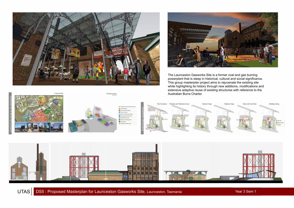
DS5 : Proposed Masterplan for Launceston Gasworks Site, Launceston, TasmaniaUTAS Year 3 Sem 1
The Launceston Gasworks Site is a former coal and gas burning powerplant that is steep in historical, cultural and social significance. This group masterplan project aims to rejuvenate the existing site while highlighting its history through new additions, modifications and extensive adaptive reuse of existing structures with reference to the Australian Burra Charter.

DS5 : Proposed Masterplan for Launceston Gasworks Site, Launceston, TasmaniaUTAS Year 3 Sem 1

DS5 : The Urban Warp and Weft at Launceston Gasworks Site, Launceston, TasmaniaUTAS Year 3 Sem 1
The Urban Warp and Weft is a continuation of the proposed masterplan at the Launceston Gasworks Site. This project further develops the public spaces and adaptive reuse buildings on site. New structures and thresholds are created within and around heritage listed buildings while a community-oriented garment production facility is also included.

DS5 : The Urban Warp and Weft at Launceston Gasworks Site, Launceston, TasmaniaUTAS Year 3 Sem 1
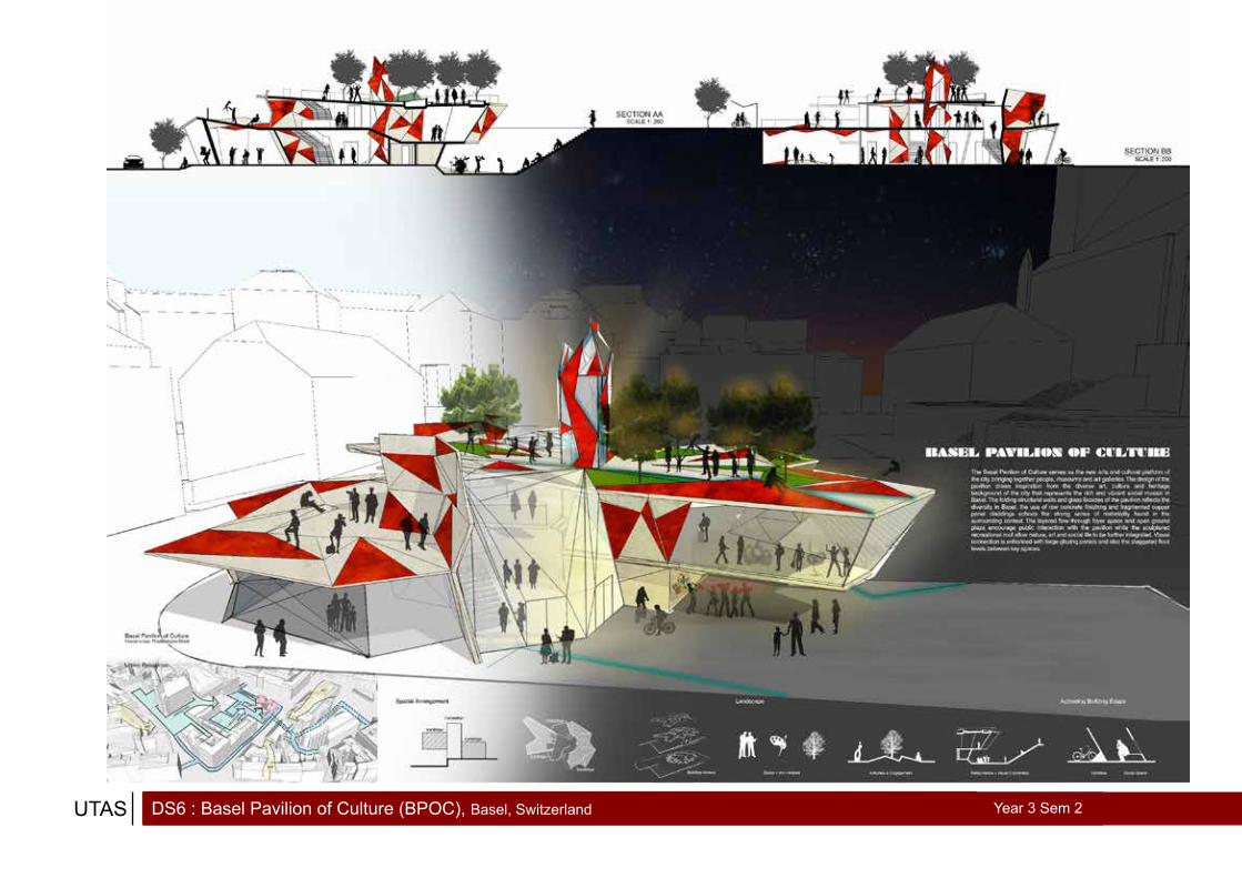
DS6 : Basel Pavilion of Culture (BPOC), Basel, Switzerland UTAS Year 3 Sem 2

DS6 : Basel Pavilion of Culture (BPOC), Basel, SwitzerlandUTAS Year 3 Sem 2

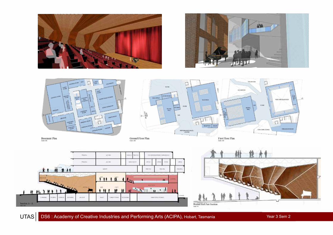
DS6 : Academy of Creative Industries and Performing Arts (ACIPA), Hobart, TasmaniaUTAS Year 3 Sem 2
The ACIPA masterplan project is the first part of a two-phase final year project. The ACIPA masterplan consist of a new building which will house the UTAS Conservertorium of Music, theaters, performing halls and a back-of-house service area.
The whole complex is attached,connected and is an extension to the adjacent heritage-listed Theater Royal building and Hedburg Garage facade.
A strong connection to local geography, cultural and social influence and the surrounding buildings is our main design focus in this project.
DS6 : Academy of Creative Industries and Performing Arts (ACIPA), Hobart, TasmaniaUTAS Year 3 Sem 2

Final Project : Academy of Creative Industries and Performing Arts (ACIPA), Hobart, TasmaniaUTAS Year 3 Sem 2
The ACIPA Project is unique both in its cross-programmed function, site condition and its geographical location. The contrast between the new build and heritage buildings, the public theaters and conservertorium of music, and the relationship between the high land mass with the waterfront creates a natural tension within the site.
By enhancing the positive tensile energy of the site through space, solid and void extrusion, the project creates a connestion between the various tension elements through visual portals. This visual connection allow the different user group to experience and appreciate the tension of the site.
tension + connection

Final Project : Academy of Creative Industries and Performing Arts (ACIPA), Hobart, TasmaniaUTAS Year 3 Sem 2

Final Project : Academy of Creative Industries and Performing Arts (ACIPA), Hobart, TasmaniaUTAS Year 3 Sem 2

Final Project : Academy of Creative Industries and Performing Arts (ACIPA), Hobart, TasmaniaUTAS Year 3 Sem 2


Other Works + Project Modelsprojects

Other WorksUTAS Year 2 Sem 2
Bridging Studio : Hot and cold climate house design
FORMER LAUNCESTON GENERAL HOSPITAL
The Former Launceston General Hospital had a long and illustrious history as one of the best equipped hospital outside of any capital city in Australia when it was first built. The former hospital was located at Upper Charles Street and is situated on top of a commanding hilltop site just down south from the city centre. The idea of the Former Launceston General Hospital was conceived by the hospital board in response to the 1935 Parliamentary Inquiry about the state of the old hospital in Mulgrave Square, the Melbourne architecture firm Stephenson and Meldrum was engaged to design the building and later the chief architect for this project was Architect Leighton Irwin. The hospital was completed in stages and the first wing was opened in September 1937, it served as the main hospital and treatment centre for northern Tasmania with facilities such as a deep therapy X-ray plant, wards, cancer clinics and a nurses’ training centre. The former Launceston Gen-eral Hospital was occupied and linked with a space-age bridge with the current new Launceston General Hospital until 1990 before being vacant. The building was recently being revived and renovated as Charles Hotel, a modern and upscale contemporary luxury hotel.
The first hospital in Launceston was ordered to be built by Major General Mac-quarie in 1821 not far from the current Holy Trinity Church, it was called His Majesty’s Colonial Hospital. In 1845, St John’s Hospital was opened at the corner of Charles and Frederick Street before operations are moved to Cornwall Hospital in 1854. By 1860, the Cornwall hospital was deemed to be in bad condition and unfit for occupation, a new hospital costing fourteen thousand pounds was built at Mulgrave Square in 1863 which will eventually become the first Launceston General Hospital. The hospital which was built in the pavilion style of architecture was considered to be second to none in the Commonwealth region while making big strides in the advancement of the medical field. However in 1925 when the hospital board engaged Melbourne architects Stephenson and Meldrum to design an extension, they found the building not being adequate for modern medicine re-quirement, thus a Parliamentary Inquiry was launched in 1935 that will eventually lead to the construction of the Former Launceston General Hospital.
The Former Launceston General Hospital at Upper Charles Street was designed by Stephenson and Meldrum from Melbourne and was built at a cost of one hun-dred and seventy seven thousand pounds. The new building included 214 beds, out-patients wing, X-ray and maternity departments and also a cancer clinic and nurses training centre. The foundation stone of the building was laid in March 1937 and the first stage of the hospital was completed in September 1937. The hospital was planned to be ‘one of the finest hospitals of its kind in the world’ with modern features such as modern heating, lighting and ventilation system, automatic lifts and state-of-the-art X-ray centre. The final building is of reinforced concrete structure with concrete floor, roof slabs and concrete external walls and was designed in the Modern Style. It can be observed that the building is stripped of any ornamentations or decorations with a strong horizontal emphasis across the main building block, an iconic sculptural external staircase was one of the design highlight of this building.
By the 1970’s the hospital board proposed to have a new general hospital just across the formal hospital, it was completed in 1982 and was functioning along-side the formal general hospital connected by a space-age bridge linkage. The former general hospital was finally vacated in 1990 and was recently revived in 2010 into the upscale Charles Hotel.
General Description
Historical Analysis
Brown, Lindam. History & Memories of Nursing at the Launceston General Hospital. Launceston: Foot & Playsted Pty Ltd, 1980.Craig, Clifford. Launceston General Hospital - First hundred Years 1863-1963. Hobart: L. G. Shea.Government Printer, 1963.Green, Anne. A Model Municipality - Places of Management, Mentoring & Medicine in Launceston. Launceston: Launceston City Council, 2007.Kell, Diane. Constructional Review. 4th. Vol. 55. Melbourne: Concrete Publishing Co. Pty Ltd, 1982.Launceston Week, Wednesday, 7 March 1990.QVMAG: History Online. http://www.qvmag.tas.gov.au.The Examiner, 2 May 1951The Examiner, Friday, August 1975.The Examiner, Wednesday, 30 April 1980.The Examiner, Monday, 7 November 1983, p.21.The Examiner, Friday, 23 August 1985.The Examiner, 18 March 1987.Thomas Ryan Photography. http://www.tryanphotos.com/Projects/Former-Launceston-HospitalThe/21209674_Xc9ffh/1416885794_BRpbVXD#!i=1416885794&k=BRpbVXD.
Bibliography
See Hoong Ping Daniel 163931AT2 : Tasmanian ModernKDA222 History & Theory in Design 44 October 2012
Fig.1. Cornwall Hospital and Infirmary, Launceston, 1854.[Clifford Craig, Launceston General Hospital - First Hundred Years1863-1963, (Hobart : L.G.Shea Government Printer, 1963),1]
Fig.2. Launceston General Hospital, Mulgrave Square, Launceston, 1863.[National Trust of Australia (Tasmania), “Launceston General Hospital”, National Trust of Australia (Tasmania), http://www.nationaltrusttas.org.au/]
Fig.3. Launceston General Hospital, Mulgrave Square, Launceston, 1863.[National Trust of Australia (Tasmania), “Launceston General Hospital”, National Trust of Australia (Tasmania), http://www.nationaltrusttas.org.au/]
Fig.4. Former Launceston General Hospital, Upper Charles Street, Launceston, 1937-1942, by Stephenson and Meldrum.[QVMAG : History Online, “Launceston General Hospital”, QVMAG : HistoryOnline, http://www.qvmag.tas.gov.au]
Fig.5. Former Launceston General Hospital, Upper Charles Street, Launceston, 1937-1942, by Stephenson and Meldrum.[Thomas Ryan Photography, “Former Launceston Hospital/The Charles”, Thomas Ryan Photography, http://www.tryanphotos.com ]
Fig.6. Former Launceston General Hospital, Upper Charles Street, Launceston, 1937-1942, by Stephenson and Meldrum.[Thomas Ryan Photography, “Former Launceston Hospital/The Charles”, Thomas Ryan Photography, http://www.tryanphotos.com ]
Fig.8. Former Launceston General Hospital, Upper Charles Street, Launceston, 1937-1942, by Stephenson and Meldrum.[Thomas Ryan Photography, “Former Launceston Hospital/The Charles”, Thomas Ryan Photography, http://www.tryanphotos.com ]
Fig.9. Former Launceston General Hospital, Upper Charles Street, Launceston, 1937-1942, by Stephenson and Meldrum.[Thomas Ryan Photography, “Former Launceston Hospital/The Charles”, Thomas Ryan Photography, http://www.tryanphotos.com ]
Fig.7. Former Launceston GeneralHospital, Upper Charles Street,Launceston, 1937-1942, by Stephenson and Meldrum.Close up detail of concrete facade.[Photograph by Daniel See]
Fig.10. Charles Hotel, Upper Charles Street, Launceston, 2008-2010, by B. Kennedy.The newly renovated Charles Hotel, a redevelopment of the Former Launceston General Hospital.[Photograph by Daniel See]
Fig.11. Charles Hotel, Upper Charles Street, Launceston, 2008-2010, by B. Kennedy.Residential units of Charles Hotel.[Photograph by Daniel See]
HTD4 : Launceston General Hospital heritage analysis

Other WorksUTAS Year 3
einterpreted
ORIG
INAL
TRAN
SFOR
MATIO
NFIN
ISHE
D PI
ECE
Original garment back panel.
Original garment front piece.
Original garment sleeves. Initial conceptual sketches exploring the design concept of Perforation, Light and Shadow.
Process of taking apart the fabric seams using a cutting blade. Studying and observing the fabric and frayed thread structure.
Creating slits and “perforations” on fabric.
Connecting differentfabric pieces using staples to enhance visual effect of seams.
Hood with perforated slit screen to provide a controlled view for the user.
Front garment panel with breast pockets reinterpreted by New jacket’s red inner lining with black pockets.
Sleeves with slits to expose new red inner lining from New jacket.
The back panel is preserved and retained in its original form.
DS5 AT1 SEE HOONG PING DANIEL 163931
My original garment on the left with my team mate’s jacket on the right.
Reflect
Research and Reinterpret
Relax
An interactive space aiming to provokecritical reflection of the gaswork site through Art, Light and Sound installations.
An interpretive museum and display area providing users with historicalinformation about the site and building.
Lounge, cafe and reception area for social gathering and a relaxed environment.
Glass roof panel to allow daylight penetration inside the vertical retort building, improving the quality of space.
4 vertical glass columns reinterpreted as the coal furnace and hoppers. The original furnace and hoppers are preserved and reinstalled outside the building with protective glass housings to provide maximum visual connection with site users.
The vertical glass columns are engraved with historical information about gas production and coal burning, list of former workers, as well as contemporary artwork by local artists.
Protruded coloured glass bars from the perforated brick facade represents the smoke and heat emitted during the gas production era. This enhanced the visual and lighting dynamics of the building during daytime and night time.
CONCEPT Preserving and Conserving the existing structure and facade while enhancing the building dynamics with an intricate play of Light andShadow elements, inspired by the light pattern created through the perforated brick facade.
DS5 AT1 SEE HOONG PING DANIEL 163931
DS5 : Vertical Retort adaptive reuse + garment modificationThis project places strong emphasis on adaptive reuse and selective modifications based on guidelines from the Australia Burra Charter. This concept of adaptive reuse is then applied on the heritage vertical retort building and on a piece of garment.

Other WorksUTAS Year 3
HTD6 : Maquette
OMA/Rem Koolhaas - Casa da Musica, Porto, PortugalSituated in the cultural heart of Europe, Casa da Musica is a connecting juncture of overlapping layers found in the historical city of Porto. The building creates a continuum between the heritage and modern city fabric, classical and contemporary music, diverse cultures, society and public spaces through various design strategies. The chiseled sculptural form, carved interior spaces and corrugated glass panels creates contrast, continuity and connection between the building’s inhabitants and the surrounding context. The use of blank materials absorb and reflect the chromatic range of urban setting, reinventing urban meaning. Casa da Musica is constantly redefined by the layers it represents, a dynamic architecture that evolves through the course of time. The maquette is constructed using stacked blank solid and transparent layers that is an abstract representation of the continuum between the physical and intangible layers that define and redefine this project.
Casa da Musica. October 24, 2005. http://www.arcspace.com/features/oma/casa-da-musica/.Open Buildings. “Casa da Musica”. Open Buildings. http://openbuildings.com/buildings/casa-da-musica-profile-1320.Tavares, Zé Luís. ArchiNed. “Casa da Musica Porto by OMA”. ArchiNed. April 19, 2005. http://www.archined.nl/nieuws/casa-da-musica-porto-by-oma/.
See Hoong Ping Daniel 163931 HTD6 AT2 2013
Daniel Libeskind - Jewish Museum, Berlin, GermanyThe Jewish Museum explore the experience of journey and spatial design, as a portal that alter users’ perception of themselves in relation to Jewish history and the modern world. Spatial design strategies such as the three main axes, the Holocaust Voids and The Garden of Exile are portals designed to evoke self realization, understanding, appreciation and interpretation of the Jewish life, society and subsequent Jewish Holocaust. The sub-conscious knowledge and emotion the building imparts require the passage of time for users to realize the impact and meaning that this other time, this other place will have on them as individuals and as a society. The maquette is designed to create voids and axes between surface planes, each creating a portal that can be interpreted differently when viewed through from different angles and perspective.
Studio Daniel Libeskind. “Jewish Museum Berlin”. Studio Daniel Libeskind. http://dan-iel-libeskind.com/projects/jewish-museum-berlin.The Libeskind Building. http://www.jmberlin.de/main/EN/04-About-The-Museum/01-Archi-tecture/01-libeskind-Building.php.
See Hoong Ping Daniel 163931 HTD6 AT2 2013
Superstudio - Continuous MonumentContinuous Monument is an idea that architecture will be created with a single act, from a single design. A singular unifying moderate utopia conceived to better understand cosmic order on earth through architecture. This concept is a response to the increased globalization, Modernist movement and International Style that homogenized the world, making architecture and culture bland and uniform while stifling human will and creativity. The monument is presented as a 3 dimensional grid, a conceptual speculation that resist interpretation and classification and is indifferent to topography, unprovocative and neutral. Continuous Monument represents two opposing ideology, a terrifying architecture that negates interaction and a sublime future with timeless serenity. It is through this opposing force from which a new architecture conception will rise from collective uniformity, enabling humanity to begin living again at the beginning. The maquette aims to explore both the opposing ideology of terror and uniform serenity.
Architectural Exhibitions and Conferences Archizoom. “Superstudio”. Architectural Exhibi-tions and Conferences Archizoom. http://archizoom.epfl.ch/page-16243-en.html.Superstudio. “THE CONTINUOUS MONUMENT: AN ARCHITECTURAL MODEL FOR TOTAL URBANIZATION”. Superstudio. http://arch122superstudio.blogspot.com.au/2012/06/continuous-monument-architectural-model_15.html.Terra Politica. “Superstudio’s Continuous Monument to Political Ambiguity”. Terra Politica. November 29, 2011. http://terrapol.com/blog/2011/11/29/superstudio-the-continuous-monu-ment-to-indecision/.
See Hoong Ping Daniel 163931 HTD6 AT2 2013
This project is about choosing and analysing an architect’s project style and influences, we are then asked to produce a short description and model that interpretes the chosen architect.

Project ModelsUTAS + ALFA
UTAS DS6 : Basel Pavilion of Culture (BPOC)
UTAS Final Project : Academy of Creative Industries and Performing Arts (ACIPA)
ALFA Final Project : Rimbun Dahan


Technical Drawingsprojects

BTD5 : Weft Space at Launceston Gasworks SiteUTAS Year 3 Sem 1
See
Hoo
ng P
ing
Dan
iel
163
931
BTD
5/IL
A.20
13.A
T3.S
EEW
EFT
SPAC
EJO
INER
Y
Reflected Ceiling PlanSc 1:50
Floor Plan (Lecture Hall)Sc 1:50
Floor Plan Discussion Hall)Sc 1:50
Section A - ASc 1:50
Section B - BSc 1:50
Section C - CSc 1:50
Section D - DSc 1:50
Joinery PlanSc 1:10
Joinery Section X-XSc 1:10
Joinery Detail 1Sc 1:2
Joinery Detail 2Sc 1:2
B B
AA
B B
AA
B B
AA
DC
DC
DC
DC
DC
DC
XX
(a)
(a)
(a)
(a)
(b)
(b)
(b)
(b)
(c)
(c)
(c)
(d)(d)
(d)
(d)
(d)
(e)(e)
(e)
(e)(e)
(e)
(f)(f)
(f)
(f)
(f)(f)
(g)
(g)
(g)
(h)
(i)
(i)
(j)
(k)(k)
(k)
(k)
30mm plywood panel backing
Hollow steel section framing
30mm perforated acoustic board
Steel hook
100 x 50mm timber support bolted to floor
Steel rack divider bolted to hollow steel section framingWheel and steel track sliding system
Rockwool insulation
Joinery Detail 1 & 2
Joinery
Joinery
JoineryJoinery
H-section steel sliding track
30mm thk plywood board
100 x 50mm timber support bolted to floor
H-section steel sliding track
60mm diameter track guiding wheel
Steel plate wheel hold-er bolted to plywood
OSRAM T5 HE 14W coloured fluorescent lamp for mood lighting
30mm thk perforated acoustic board
See Hoong Ping Daniel (163931) BTD/ILA.2013.AT3.SEE
IEQ Calculations for Weft Space
Acoustics:
RT requirements under Australian Standards for Teaching Space: 0.4 - 0.6 RT
My weft space is used as a Lecture Hall and Tutorial Discussion Hall, both are under teaching space.
Lecture Hall calculations:
Surface Area/Quantity Absorption coefficient/sabins Total
Ceiling
Wall+Door
Cupboard
Windows
Humans
Floor
96 m2
73.31 m2
32.44 m2
21.6 m2
60
96 m2
0.50
0.1
0.50
0.09
0.46
0.30
48
7.3
16.22
1.9
27.6
28.8
TOTAL 129.82
RT = 0.16V / total of SA
= 0.16 (328) / 129.82
= 0.40
Tutorial Discussion Hall calculations:
Surface Area/Quantity Absorption coefficient/sabins Total
Ceiling
Wall+Door
Cupboard
Windows
Humans
Floor
Tables
96 m2
73.31 m2
32.44 m2
21.6 m2
42
81.6 m2
14.4 m2
0.50
0.1
0.50
0.09
0.46
0.30
0.1
48
7.3
16.22
1.9
19.32
24.48
1.44
TOTAL 118.66
RT = 0.16V / total of SA
= 0.16 (328) / 118.66
= 0.44
IEQ Calculations for Weft Space:
Daylight:
DF requirements is 2 - 5%. Minimum lux levels for teaching space is 320 lux.
Weft Space calculations:
W = 21.6 m2T = 0.8O = 90M = 0.8A = 21.6 + 32.44 + 73,31 + 96 + 96 = 319.35 m2R = (96 x 0.1) + (96 x 0.4) + (21.6 x 0.1) + (77.31 x 0.2) + (32.44 x 0.4) / 319.35 = 9.6 + 38.4 + 2.16 + 14.67 + 13 / 319.35 = 0.24
DF = WTOM / A(1-R2) = 21.6 x 0.8 x 90 x 0.8 / 319.35 (1-(0.24)2) = 1244.16 / 319.35(0.9424) = 4.13
Lux Levels = 4.13% x 10000 Lux = 413 Lux
Artificial Lighting:
Power density requirements under NCC for general teaching space is 8 w/m2.
Minimum lux levels for teaching space is 320 lux.
Weft Space calculations:
Type of light = Avalon Direct Lighting (T26 34W)E = 320a = 6b = 16P* = 2.35PL = 42f = 100
N = EabP* / PL x f = 320 x 6 x 16 x 2.35 / 42 x 100 = 72192 / 4200 = 17
Power Density = 17 x 34W / 96 m2 = 6 W/m2
Schedule of Materials and Finishes:(a) Perforated Acoustic Board(b) 2000 x 2000 Perforated Acoustic Ceiling(c) Carpet(d) Plywood Panel Wall(e) 400 x 400 Hollow Steel Structure(f) 1500 x 1200 Double-Glazed Top Hung Window Panel(g) Steel I-Beam(h) Marble Counter Top(I) White Board / Projection Panel(j) Foldable Timber Tables(k) Foldable Chairs
Lighting Schedule:(1) Avalon Direct Lighting 1250mm T26 34W (P*=2.35, PL=42)(2) OSRAM T5 HE 14W coloured fluorescent lamp (mood lighting)(3) Light Switch
(Tutorial
My joinery is an integrated wall mounted storage system for my multipurpose weft space. This integrated storage system enables efficient furniture storage for two different space usage. By responding to my over-all design concept of layering materials and spaces, this storage system forms one of the main interior wall facade and acts as an acoustic control by having a perforated acoustic panel facade. Mood lighting is also inte-grated into the top and bottom edge of the storage unit. The sliding inter-nal storage rack is designed to be an interchangable modular unit to accomodate different furnitures and storage requirements of the weft space. The storage rack shown here is designed for foldable chairs to be slot and hung in layers at the bottom rack and top hookrespectively.
Relationship to Design Ideas:
See Hoong Ping Daniel (163931) BTD/ILA.2013.AT3.SEE
IEQ Calculations for Weft Space
Acoustics:
RT requirements under Australian Standards for Teaching Space: 0.4 - 0.6 RT
My weft space is used as a Lecture Hall and Tutorial Discussion Hall, both are under teaching space.
Lecture Hall calculations:
Surface Area/Quantity Absorption coefficient/sabins Total
Ceiling
Wall+Door
Cupboard
Windows
Humans
Floor
96 m2
73.31 m2
32.44 m2
21.6 m2
60
96 m2
0.50
0.1
0.50
0.09
0.46
0.30
48
7.3
16.22
1.9
27.6
28.8
TOTAL 129.82
RT = 0.16V / total of SA
= 0.16 (328) / 129.82
= 0.40
Tutorial Discussion Hall calculations:
Surface Area/Quantity Absorption coefficient/sabins Total
Ceiling
Wall+Door
Cupboard
Windows
Humans
Floor
Tables
96 m2
73.31 m2
32.44 m2
21.6 m2
42
81.6 m2
14.4 m2
0.50
0.1
0.50
0.09
0.46
0.30
0.1
48
7.3
16.22
1.9
19.32
24.48
1.44
TOTAL 118.66
RT = 0.16V / total of SA
= 0.16 (328) / 118.66
= 0.44
(full calculations please refer to attached A4 calculation sheet)
Daylight:
DF requirements is 2 - 5%. Minimum lux levels for teaching space is 320 lux.
Weft Space calculations:
W = 21.6 m2T = 0.8O = 90M = 0.8A = 21.6 + 32.44 + 73,31 + 96 + 96 = 319.35 m2R = (96 x 0.1) + (96 x 0.4) + (21.6 x 0.1) + (77.31 x 0.2) + (32.44 x 0.4) / 319.35 = 9.6 + 38.4 + 2.16 + 14.67 + 13 / 319.35 = 0.24
DF = WTOM / A(1-R2) = 21.6 x 0.8 x 90 x 0.8 / 319.35 (1-(0.24)2) = 1244.16 / 319.35(0.9424) = 4.13
Lux Levels = 4.13% x 10000 Lux = 413 Lux
Artificial Lighting:
Power density requirements under NCC for general teaching space is 8 w/m2.
Minimum lux levels for teaching space is 320 lux.
Weft Space calculations:
Type of light = Avalon Direct Lighting (T26 34W)E = 320a = 6b = 16P* = 2.35PL = 42f = 100
N = EabP* / PL x f = 320 x 6 x 16 x 2.35 / 42 x 100 = 72192 / 4200 = 17
Power Density = 17 x 34W / 96 m2 = 6 W/m2
The integrated wall mounted storage unit can be pull and extended out to alter the shape of the space for different discussion sessions.
The outer edge of the weft spacecan be transformed into an informal alcove with views down to the agora and plaza below. This edge can also be used for informal tutorial discussion sessions.
Diagrams:

BTD6 : Generic Construction SystemUTAS Year 3 Sem 2
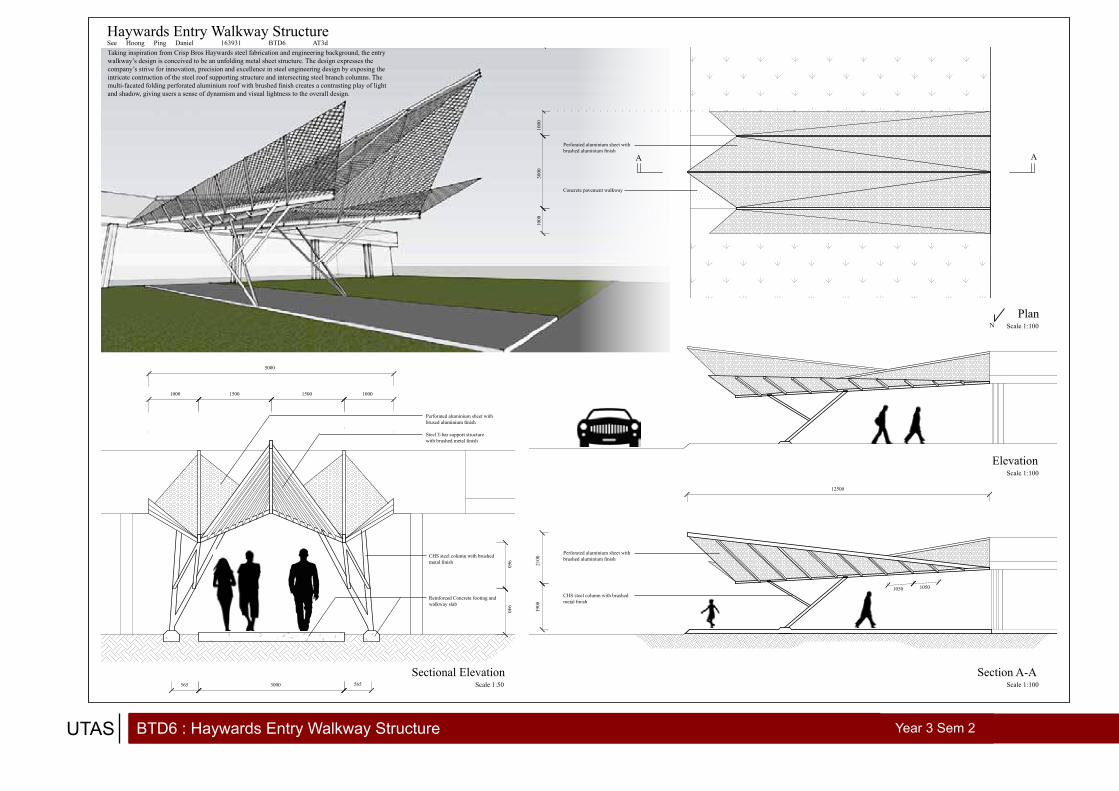
BTD6 : Haywards Entry Walkway StructureUTAS Year 3 Sem 2
PlanScale 1:100
ElevationScale 1:100
Section A-AScale 1:100
A A
Sectional ElevationScale 1:50
1000
3000
1000
2100
1900
12500
5000
1000 10001500 1500
3000565 565
960940
Perforated aluminium sheet with brushed aluminium finish
CHS steel column with brushed metal finish
Perforated aluminium sheet with brushed aluminium finish
Concrete pavement walkway
N
CHS steel column with brushed metal finish
Reinforced Concrete footing and walkway slab
Perforated aluminium sheet with brused aluminium finish
Steel T-bar support structure with brushed metal finish
Taking inspiration from Crisp Bros Haywards steel fabrication and engineering background, the entry walkway’s design is conceived to be an unfolding metal sheet structure. The design expresses the company’s strive for innovation, precision and excellence in steel engineering design by exposing the intricate contruction of the steel roof supporting structure and intersecting steel branch columns. The multi-facated folding perforated aluminium roof with brushed finish creates a contrasting play of light and shadow, giving users a sense of dynamism and visual lightness to the overall design.
Haywards Entry Walkway StructureSee Hoong Ping Daniel 163931 BTD6 AT3d
1050 1050

BTD6 : FInal Project DetailsUTAS Year 3
Back of house spaces are are situated on one level to maximize efficiency and centralise services
Spaces are arrange at the edge of Sun Street to maximize solar gain from the east
Big beam spans are used to open up floor space, allowing flexible space arrangement
A central void is created to allow diffused natural daylight to enter the deep building site
Vignettes


photography

PhotographyDANIEL
1. Manhattan, New York
2. Bird-eye view from Empire State Tower
3. Golden Gate Bridge, San Francisco
4. Storage Hut, Ben Lomond, Tasmania
1 2
3
4

PhotographyDANIEL
5. Aurora Australis, Mt. Wellington, Tasmania
6. Milky Way, Low Head
7. Sunset, West Coast, Tasmania
8. Reflection, Sea Port, Launceston
5
6
7
8

PhotographyDANIEL
9. Buskers, Salamanca Market
10. Street Art, Melbourne
11. South Cape Bay, Tasmania
9
10 11

d a n i e l s e e
“ A great building must begin with the unmeasurable, must go through measurable means when it is being designed and in the end must be unmeasurable. “
Louis I. Kahn