cylinderpowertsubaki - tsubaki europe
TRANSCRIPT
1
TSUBAKIPOWERCYLINDER
Lini-Power Jack
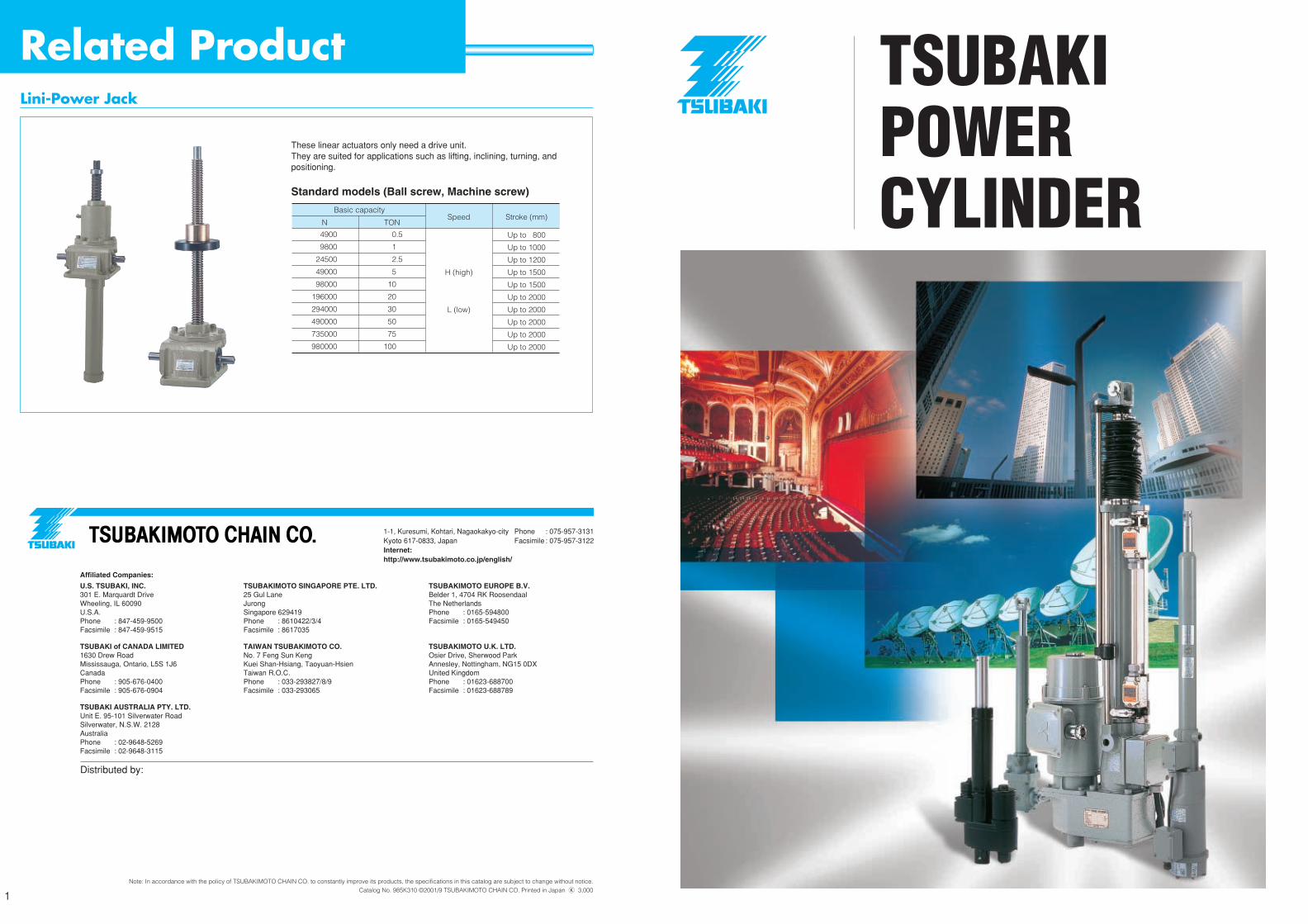
These linear actuators only need a drive unit.They are suited for applications such as lifting, inclining, turning, andpositioning.
Standard models (Ball screw, Machine screw)
Note: In accordance with the policy of TSUBAKIMOTO CHAIN CO. to constantly improve its products, the specifications in this catalog are subject to change without notice.Catalog No. 985K310 ©2001/9 TSUBAKIMOTO CHAIN CO. Printed in Japan K 3,000
Affiliated Companies:
U.S. TSUBAKI, INC.301 E. Marquardt DriveWheeling, IL 60090 U.S.A.Phone : 847-459-9500Facsimile : 847-459-9515
TSUBAKI of CANADA LIMITED1630 Drew Road Mississauga, Ontario, L5S 1J6 CanadaPhone : 905-676-0400Facsimile : 905-676-0904
TSUBAKI AUSTRALIA PTY. LTD.Unit E. 95-101 Silverwater RoadSilverwater, N.S.W. 2128AustraliaPhone : 02-9648-5269Facsimile : 02-9648-3115
TSUBAKIMOTO SINGAPORE PTE. LTD.25 Gul Lane Jurong Singapore 629419Phone : 8610422/3/4Facsimile : 8617035
TAIWAN TSUBAKIMOTO CO.No. 7 Feng Sun Keng Kuei Shan-Hsiang, Taoyuan-Hsien Taiwan R.O.C.Phone : 033-293827/8/9Facsimile : 033-293065
TSUBAKIMOTO EUROPE B.V.Belder 1, 4704 RK RoosendaalThe NetherlandsPhone : 0165-594800Facsimile : 0165-549450
TSUBAKIMOTO U.K. LTD.Osier Drive, Sherwood ParkAnnesley, Nottingham, NG15 0DX United KingdomPhone : 01623-688700Facsimile : 01623-688789
1-1, Kuresumi, Kohtari, Nagaokakyo-city Phone : 075-957-3131Kyoto 617-0833, Japan Facsimile : 075-957-3122Internet:http://www.tsubakimoto.co.jp/english/
Distributed by:
N
Basic capacity
4900
9800
24500
49000
98000
196000
294000
490000
735000
980000
TON
0.5
1
2.5
5
10
20
30
50
75
100
Speed
H (high)
L (low)
Stroke (mm)
Up to 800
Up to 1000
Up to 1200
Up to 1500
Up to 1500
Up to 2000
Up to 2000
Up to 2000
Up to 2000
Up to 2000
Related Product

With Electromagnetic brake motorT series, G series,Ultra heavy duty series
Ready for outdoor useT series, G series , Ultra heavy duty series, F series, Battery series
Rod anti-rotation deviceavailable as made -to-orderIf the actuator rod end is free or connected to wire rope, anti-rotation device for a rod is needed.
T series, G series , Ultra heavy duty series
Easy and economical to combine with your equipmentThe mechanical type motor driven actuator reduces the need for compressors, piping valves or hydraulic units, making the equipment simpler and more economical. The device can be treated as a motor and allows for simple remote control. Furthermore, the simple construction and long life grease provide for more economical maintenance.
Battery powered actuatorDC motor type
Battery series, F series
Three phase motor with brakefor precise positioning, and rigid load holding
T series, G series , Ultra heavy duty series
Internal position sensor; Limit switch typeavailable at your choice for signaling the position of the stroke
T series, G series , F series
Potentiometer or Rotary encoderavailable at your choice for remote control operation
T series, G series , Ultra heavy duty series
BellowsTo be used in dusty area at your choice
T series, G series , Ultra heavy duty series, F series
External limit switchesavailable at your choice for adjusting stroke of the actuator
T series, G series , Ultra heavy duty series, F series
Multi type actuatoravailable for synchronized operation with one motorMulti seriesPress loaded
stopping devicefor safety and thrust sensingA combination of dish springs and limit switches is used to provide thrust sensing and press loaded stopping.
Available for T series LPTC type and , G series LPGC type, Battery series
Jack type(Ball screw or trapezoidal screw)Lini-power jack available by a separate catalog1.96-980KN (0.2-100tf)
Mounting type and an end fittingClevis or trunnion mount and I type end fitting are available for T series, G series , Ultra heavy duty seriesF series -clevis mount only
HIGH PERFORMANCE LINEAR ACTUATORS OFFERING EFFICIENT, CLEAN AND QUIET DRIVE..... ENVIRONMENTAL CONSCIOUSNESS
32

43
314k
32000
c
c
c
c
157k
16000
c
c
c
c
118k
12000
c
c
c
c
78.4k
8000
c
c
c
58.8k
6000
c
c
c
39.2k
4000
c
c
c
c
c
c
c
c
19.6k
2000
c
c
c
c
c
c
9.80k
1000
c
c
c
c
c
c
4.90k
500
c
c
c
c
c
1230k
125000
7.5/9
c
c
c
c
882k
90000
7.5/9
10/12
c
c
c
c
617k
63000
7.5/9
10/12
15/18
c
c
c
c
314k
32000
10/12
15/18
20/24
c
c
c
c
157k
16000
14.5/17.5
20/24
31/37
c
c
c
c
118k
12000
10/12
18/22
30/36
c
c
c
c
78.4k
8000
10/12
20/24
30/36
43/52
c
c
c
58.8k
6000
6.3/7.6
17.5/21
25/30
42/50
c
c
c
39.2k
4000
9/11
25/30
35/42
60/72
c
c
c
c
c
c
c
c
c
19.6k
2000
12.5/15
25/30
50/60
75/90
c
c
c
c
c
c
c
c
9.80k
1000
12.5/15
25/30
50/60
100/120
c
c
c
c
c
c
c
4.90k
500
12.5/15
25/30
50/60
100/120
c
c
c
c
c
c
2.45k
250
12.5/15
25/30
50/60
100/120
c
c
c
c
c
314k
32000
10/12
15/18
20/24
c
c
c
c
157k
16000
14.5/17.5
20/24
31/37
c
c
c
c
118k
12000
10/12
18/22
30/36
c
c
c
c
78.4k
8000
10/12
20/24
30/36
43/52
c
c
c
58.8k
6000
6.3/7.6
17.5/21
25/30
42/50
c
c
c
Depending upon the type and input r.p.m..
See Max. Input r.p.m. on page 55.
Multi SeriesT Series Ultra Heavy
Duty Series TB type TC typeTB type TC type
• Synchronized operation of multiple units
$: Fitted on the standard units !: Multi series available as optional parts*Note: Potentiometer cannot be used with Clevis mounting type ': Available on made-to-order basis
• Ultra heavy duty
!
$
!
!
!
$
'
!
$
!
!
!
$
$
'
!
'
'
'
'
$
!
!
!
'
$
$
!
!
!
!
$
!
!
!
!
$
$
$
'
!
!
!
!
$
!
!
!
!
OutdoorOutdoorOutdoor
39.2k
4000
9/11
25/30
35/42
60/72
c
c
c
c
c
c
c
c
c
19.6k
2000
12.5/15
25/30
50/60
75/90
c
c
c
c
c
c
c
c
9.80k
1000
12.5/15
25/30
50/60
100/120
c
c
c
c
c
c
c
4.90k
500
12.5/15
25/30
50/60
100/120
c
c
c
c
c
c
2.45k
250
12.5/15
25/30
50/60
100/120
c
c
c
c
c
3.00k
306
25/30
50/60
67/80
c
c
c
c
c
c
c
c
c
1.50k
153
25/30
75/90
100/120
c
c
c
c
c
c
c
c
c
1.00k
102
25/30
75/90
c
c
c
c
c
c
c
c
c
700
71.4
25/30
75/90
c
c
c
c
c
c
c
c
c
T SeriesBattery SeriesF Series
G Series
GA-TK type GC-TK type TB typeMid.Small
• Compact and light• DC 12V or 24V
• For general industrial use, hopper gate & dumper • High grade series with various optional parts
• For general industrial use, hopper gate & dumper • High grade series with various optional parts
$
$
'
!
!
!
!
$
!
!
!
!
$
$
'
!
$
!
!
!
!
!
!
!
$
$
!
!
!
!
$
!
!
!
!
$
$
$
!
$
!
!
!
$$
$
$
'
!
!
!
!
$
!
!
!
!
OutdoorOutdoorOutdoorOutdoor
100/120200/240
100/120200/240
3.00k
306
25/30
50/60
67/80
c
c
c
c
c
c
c
c
c
1.50k
153
25/30
75/90
100/120
c
c
c
c
c
c
c
c
c
1.00k
102
25/30
75/90
c
c
c
c
c
c
c
c
c
700
71.4
25/30
75/90
c
c
c
c
c
c
c
c
c
392
40
15
c
c
c
c
c
196
20
24
c
c
c
c
c
98.0
10
54
c
c
c
c
c
1.47k
150
17
c
c
c
c
980
100
27
c
c
c
c
392
40
15
c
c
c
c
98.0
10
50
c
c
c
c
N
kgf
Slow
Low
Medium
High
3000mm
2000mm
1500mm
1200mm
1000mm
800mm
600mm
500mm
400mm
300mm
200mm
150mm
100mm
50mm
100/120200/240
100/120200/240
Environment
Brake
Shaft for manual operation
Anti-rod rotation
Limit switch for stroke adjusting
Built-in L.S. for positioning
Potentiometer*
Rotary encoder
End fitting (type U)
End fitting (type I)
Bellows
Clevis*
Trunnion mounting adapter
Press contact stopping
Thrust
Speed(mm/sec.)50/60Hz
Stroke
GB-K type available
Battery Cylinder
6
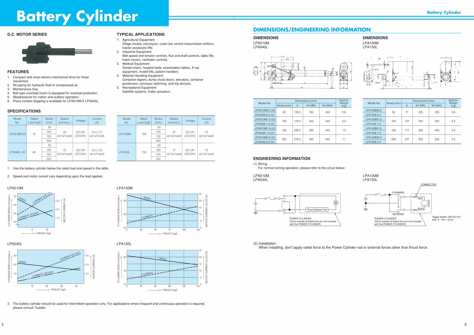
D.C. MOTOR SERIES
FEATURES1. Compact and clean electro-mechanical drive for linear
movement.2. No piping for hydraulic fluid or compressed air.3. Maintenance-free.4. Ball type overload clutch is equipped for overload protection.5. Weatherproof for indoor and outdoor operation.6. Press contact stopping is available for LPA010M & LPA040L.
TYPICAL APPLICATIONS1. Agricultural Equipment
Silage chutes, conveyors, cutter bar control transmission shifters,tractor accessory lifts.
2. Industrial EquipmentBelt speed and tension controls, flue and draft controls, table lifts,hatch covers, ventilator controls.
3. Medical EquipmentDental chairs, hospital beds, examination tables, X-rayequipment, invalid lifts, patient handlers.
4. Material Handling EquipmentContainer tippers, dump chute doors, elevators, containerpositioners, conveyor switching, and trip devices.
5. Recreational EquipmentSatellite systems, trailer actuators.
Super Mini Series
5
Battery Cylinder
SPECIFICATIONS
1. Use the battery cylinder below the rated load and speed in the table.
2. Speed and motor current vary depending upon the load applied.
LPA010M LPA100M
LPA040L LPA150L
3. The battery cylinder should be used for intermittent operation only. For applications where frequent and continuous operation is required,please consult Tsubaki.
ModelNo.
RatedLoad (kgf)
Stroke(mm)
Speed(mm/sec.)
50(at full load)
15(at full load)
DC12V(DC24V)
DC12V(DC24V)
3.4 (1.7)(at full load)
3.0 (1.5)(at full load)
VoltageCurrent
(A)
50
100
150
200
50
100
150
200
LPA010M (V)
LPA040L (V)
10
40
ModelNo.
RatedLoad (kgf)
Stroke(mm)
Speed(mm/sec.)
27(at full load)
17(at full load)
DC12V(DC24V)
DC12V(DC24V)
13(at full load)
13(at full load)
VoltageCurrent
(A)
50
100
150
200
50
100
150
200
LPA100M
LPA150L
100
150
40
1.0
2.0
3.0
5 10
50
60
70 SPEED
CURRENT (DC24V)
CURRENT (DC12V)
THRUST (kgf)
CY
LIN
DE
R S
PE
ED
(m
m/s
ec.)
MO
TOR
CU
RR
EN
T (A
)
0
5
10
15
20
25
25 50 75 100 1250
SPEED
CURRENT
THRUST (kgf)
CY
LIN
DE
R S
PE
ED
(m
m/s
ec.)
MO
TOR
CU
RR
EN
T (A
) D
C12
V
30
25
20
10
20
30
1.0
2.0
3.0
10 20 30 40
SPEED
CURRENT (DC24V)
CURRENT (DC12V)
THRUST (kgf)
CY
LIN
DE
R S
PE
ED
(m
m/s
ec.)
MO
TOR
CU
RR
EN
T (A
)
0
5
10
15
20
25
30 60 90 120 1500
SPEED
CURRENT
THRUST (kgf)
CY
LIN
DE
R S
PE
ED
(m
m/s
ec.)
MO
TOR
CU
RR
EN
T (A
) D
C12
V
20
15
10
DIMENSIONS/ENGINEERING INFORMATIONDIMENSIONSLPA010MLPA040L
DIMENSIONSLPA100MLPA150L
LPA010M0.5 (V)
LPA040L0.5 (V)
LPA010M1.0 (V)
LPA040L1.0 (V)
LPA010M1.5 (V)
LPA040L1.5 (V)
LPA010M2.0 (V)
LPA040L2.0 (V)
Dimensions (mm)Model No.
Stroke (mm) A XA MIN. XA MAX.
Approx.Weight
(kg)
50
100
150
200
129.5
179.5
229.5
279.5
190
240
290
340
240
340
440
540
0.8
0.9
1.0
1.1
LPA100M0.5
LPA150L0.5
LPA100M1.0
LPA150L1.0
LPA100M1.5
LPA150L1.5
LPA100M2.0
LPA150L2.0
Dimensions (mm)Model No. Stroke (mm)
A XA MIN. XA MAX.
Approx.Weight
(kg)
50
100
150
200
77
127
177
227
205
255
305
355
255
355
455
555
3.6
3.9
4.2
4.5
ENGINEERING INFORMATION(1) Wiring
For normal inching operation, please refer to the circuit below;
LPA010M LPA100MLPA040L LPA150L
(2) InstallationWhen installing, don’t apply radial force to the Power Cylinder rod or external forces other than thrust force.
M
Thrust Detection Part
POWER CYLINDER(Parts outside of dotted line are not included with the POWER CYLINDER)
POWER CYLINDER(Parts outside of dotted line are not included with the POWER CYLINDER)
CONNECTOR
Toggle Switch: 30A DC12Vwire: 5 ~ 6m × 2mm2
REVERSE
FORWARD
RED
BLACK

STANDARD SPECIFICATIONS
MOTOR SPECIFICATIONS AMBIENT CONDITIONS
F Series
8
FEATURES1. Compact design with right angled connection between motor and actuator.2. Right angled two-way clevis holes make four position of mounting.3. Press stopping is available with overload detecting unit (Option).4. Both DC (12V or 24V) and AC (100V or 200V with AC adapter) are applicable for power source.5. Variety of options are available such as stroke adjustment external LS, bellows, position detecting unit. AC adapter, overload detecting unit and
so on.
F Series
7
Gear casing Nut Outer cylinderTube retainer
Rod End fitting
Screw shaft
DC motor
Do not loosenset screws
Structure
MODEL No.
LPF 040 L 2.0 V L K2 P JPower Cylinder F Series J : Bellows
P : Potentiometer(Can’t be used together with K2)
L : LS for Stroke adjustment(Can’t be installed onto the model with 50 mm stroke)
K2 : Internal LS for positioning(Can’t be used together with potentiometer)
Thrust 010 : 100N 10.2kgf020 : 200N 20.4kgf040 : 400N 40.8kgf
Speed (L : Low M : Mid H : High)
Stroke (2.0 : 200mm)
V : DC 24V (No mark : DC 12V)
Rated Thrust Stroke
mm
Speed
mm/s
Voltage
V
Rated load current
A
Locked current
A
Note: 1. Model No. should be selected in consideration of locked current.2. Figures in ( ) are shown as current for DC 24V models.
LPF010H0.5
LPF010H1.0
LPF010H1.5
LPF010H2.0
LPF010H3.0
LPF020M0.5
LPF020M1.0
LPF020M1.5
LPF020M2.0
LPF020M3.0
LPF040L0.5
LPF040L1.0
LPF040L1.5
LPF040L2.0
LPF040L3.0
LPF010H0.5 V
LPF010H1.0 V
LPF010H1.5 V
LPF010H2.0 V
LPF010H3.0 V
LPF020M0.5 V
LPF020M1.0 V
LPF020M1.5 V
LPF020M2.0 V
LPF020M3.0 V
LPF040L0.5 V
LPF040L1.0 V
LPF040L1.5 V
LPF040L2.0 V
LPF040L3.0 V
10.2
20.4
40.8
54
24
15
100
200
400
50
100
150
200
300
50
100
150
200
300
50
100
150
200
300
N kgf
DC12
or
DC24
3.2
(1.6)
3.2
(1.6)
3.7
(1.8)
16.7
(7.5)
16.7
(7.5)
16.7
(7.5)
Model No.
Model No.
LPF010H
LPF010H V
LPF020M
LPF020M V
LPF040L
LPF040L V
Voltage
V
12
24
12
24
12
24
Output
WRating
29 5 Minutes
Type Outdoor type
–15°C ~ 40°C
Less than 85%
Less than 1G
Less than 1000m
Outdoor use
Atm
osp
here
Ambient temp.
Humidity
Shock
Altitude
Environment
DM
FORWARD
Overload Detection UnitFUSE 12V 10A
24V 5A
FUSE 12V 10A24V 5A
Pow
er C
ylin
der
Pow
er C
ylin
der
Term
inal
No.
DC PowerSource formotor
BLACKDC
REDFUSE
REVERSE
a
b
C
C
a
b
REFERENCE CIRCUIT: DYNAMIC BRAKE CIRCUIT OVERLOAD DETECTION UNIT
BLACK
RED
F
R
+V
0V
M1
M2
AC Adapter
Term
inal
No.
AC ADAPTER
0V
100V
200V
F
R
COM
M1
M2
Pow
er C
ylin
derBLACK
AC200VAC100V
RED
When connecting the black wire to + and red wire to –, the rod goes forward
Use the following capacity of the relayDC 12V Model: 30A or greater (14VDC)DC 24V Model: 30A or greater (28VDC)
Note: Diameter of electric cable should be greater than 2 mm2
when distance between motor ~ overload detecting unit and DC power source is within 3 m.
DM
DM
WIRING DIAGRAMS

CHARACTERISTICS GRAPHDC12V DC24VLPF010H LPF010H V
F Series
10
SELECTION AND INSTRUCTION FOR OPERATIONSELECTIONThe following information is necessary for the selection of F series.1. Application2. Required Thrust or Load N (kgf)3. Stroke mm4. Speed mm/sec5. Frequency of operation cycle/min6. Voltage of power source
SELECTION PROCEDURE1. Selection of Model No.
Select the suitable model number from the chart of standard specification (page 8) based on Thrust (N or kgf), Stroke (mm), Speed (mm/sec.)and so on.
2. Confirmation of special featuresFrequency of operation must be kept at the following:
Allowable number of motor starts : 2 times/min. or lessAllowable working time rate : 25% ED or less
INSTRUCTION FOR OPERATION1. Performance
Operative speed and motor current varies depending on actual load applied to the rod. Refer to the characteristics graph at page 10 for thedetail.F series Power Cylinders cannot be operate in synchronicity due to change of speed by applied load as a characteristic of DC motor. Life isapproximately 15,000 times rod’s reciprocating motion.
2. Power sourceWhen using AC power source by transformer in stead of DC battery power source, capacity of transformer should be large enough to avoiddropping of voltage. (AC adapter for output voltage DC 24V is available as optional parts.)
3. VoltageDC 12V type (10 ~ 14V) and DC 24V (20 ~ 28V) are available. Operative speed may change depending on actual voltage.
4. MaintenanceActuator portion and reducer portion are pre-greased. Greasing is not required.
5. Press stopping operationPress stopping is available with overload detecting unit. (overload detection unit must be used with Power Cylinder in this case)CAUTION: Press stopping is not available for the standard model because it doesn’t have any overload detecting units.
6. Rod rotating preventionIt is necessary to prevent rod rotating because rotating torque as shown below applies to the rod when operating.LPF010H: Max 0.14 NmLPF020M: Max 0.28 NmLPF040L: Max 0.55 Nm
7. Frequency of operationF series Power Cylinder is designed for low frequency of operation, however it can be also used for inching operation if frequency of operationis less than 10 times/min.
8. Outdoor useF Series Power Cylinder itself is for outdoor use. Waterproof connector must be prepared and connected to the end of the motor cable.
9. InstallationWhen installing, do not apply radial force to the rod or external forces other than thrust force.Power Cylinder should be connected with connecting pins to the equipment. Both clevis pin and end fitting pin should be also adjusted inphase.
F Series
9
50
0
60
70
2.0
0
4.0
THRUST (Nkgf)
CU
RR
EN
T (A
)
505.10 10010.2
SPEED
CURRENT
SP
EE
D (
mm
/s)
50
0
60
70
2.0
0
4.0
THRUST (Nkgf)
CU
RR
EN
T (A
)
505.10 10010.2
SPEED
CURRENT
SP
EE
D (
mm
/s)
10
20
30
0
1.0
0
2.0
3.0
THRUST (Nkgf)
CU
RR
EN
T (A
)
505.1 10010.20 15015.3 20020.4
010010.2 20020.40 30030.6 40040.8
SPEED
CURRENT
SP
EE
D (
mm
/s)
10
20
30
0
1.0
0
2.0
3.0
THRUST (Nkgf)
CU
RR
EN
T (A
)
505.1 10010.20 15015.3 20020.4
SPEED
CURRENT
SP
EE
D (
mm
/s)
10
20
0
2.0
4.0
THRUST (Nkgf)
CU
RR
EN
T (A
)
SPEED
CURRENT
SP
EE
D (
mm
/s)
010010.2 20020.40 30030.6 40040.8
10
20
0
2.0
4.0
THRUST (Nkgf)
CU
RR
EN
T (A
)
SPEED
CURRENT
SP
EE
D (
mm
/s)
LPF020M LPF020M V
LPF040L LPF040L V
Note: Data in the graphs is based on DC 12V/24V, ambient temp 20°C. Speed and motor current depend on conditions of power source andambient temp.

POSITION DETECTING UNIT
INTERNAL STRUCTUREThe following two built-in units are available for position detection.
1. INTERNAL LIMIT SWITCH FOR POSITION DETECTION 2. POTENTIOMETER
Note: Internal LS for position detection cannot be used together with potentiometer and vice versa.
SPECIFICATIONS OF POSITION DETECTING UNIT
F Series
12
DIMENSIONS
Basic type
WITH LIMIT SWITCH FOR STROKE ADJUSTMENTNote: Limit switch for stroke adjustment cannot be installed onto the model with 50 mm stroke.
WITH BELLOWS WITH POSITION DETECTION UNIT
F Series
11
8 XA
35
30 121
035
038
51
022
A8 3.5 44
22
2018 59
.4
300
08
+0.2
0
AWG18(0.8mm2)
42
22
08
+0.2
0
11
0.75mm2 300mm
121
R46
038
3.5 2245
2439
.4
300
9 22
055
31
4346
1078(25)79
22 57
44
18
(12)
Cabtire CableRefer to page 12 for the details of wiring
XA
LPF010H0.5
LPF010H1.0
LPF010H1.5
LPF010H2.0
LPF010H3.0
LPF020M0.5
LPF020M1.0
LPF020M1.5
LPF020M2.0
LPF020M3.0
LPF040L0.5
LPF040L1.0
LPF040L1.5
LPF040L2.0
LPF040L3.0
LPF010H0.5 V
LPF010H1.0 V
LPF010H1.5 V
LPF010H2.0 V
LPF010H3.0 V
LPF020M0.5 V
LPF020M1.0 V
LPF020M1.5 V
LPF020M2.0 V
LPF020M3.0 V
LPF040L0.5 V
LPF040L1.0 V
LPF040L1.5 V
LPF040L2.0 V
LPF040L3.0 V
10.2
20.4
40.8
100
200
400
50
100
150
200
300
50
100
150
200
300
50
100
150
200
300
162
212
262
312
412
162
212
262
312
412
162
212
262
312
412
1.0
1.2
1.4
1.6
2.0
1.0
1.2
1.4
1.6
2.0
1.0
1.2
1.4
1.6
2.0
MIN.
220
270
320
370
480
220
270
320
370
480
220
270
320
370
480
MAX.
270
370
470
570
780
270
370
470
570
780
270
370
470
570
780
N kgf mm kgA
Model No.Approx.weight
Note: In case of DC 24V, symbol “V” is added to the end of the model number.
StrokeThrustDimensions
1. INTERNAL LIMIT SWITCH FOR POSITIONDETECTION
For space saving or hard environments such as dust, corrosion etc.
Limit Switch Set-Up1. Operate Power Cylinder to confirm direction of LS cam before
installing the Power Cylinder.
2. Install the Power Cylinder, then adjust where the position ofstroke is to be stopped or detected.
3. Rotate LS cam, then fix it at the position where the micro switchworks by tightening set screws taking into consideration thecoasting distance of the stroke.
2. POTENTIOMETERPotentiometer is a variable resister to output electrical signals bystroke.Printed circuit board and stroke indication meter may be usedtogether with the potentiometer.Resister is preset by model of Power Cylinder before delivery.If the actuator rod is rotated before installation, the stroke position willbe out of phase with potentiometer. After installation adjust the phasecorrectly.
SS-5GL2(OMRON)
AC 250V 2A (cos0=0.4)
0.5mm2 × 6C, length 500mmCabtire Cable
Type
Capacity
Connection
Contactconfiguration
RedBlack
White
LS1 LS2
Yellow
Brown
Green
Total resistance
Power rating
Insulation rating
Effective electrical angle
Effective angle of rotation
Connection
Type CP-30(Kyoei Tsushin Kogyo)
1kΩ0.75W
AC1000V 1min.
355° ±5°
360° (Infinite)
0.5mm2 × 3C, length 500mmCabtire Cable
Black Red
WhiteRod Reverse Rod Forward
LS Cam
Set Screw
Model No.
Current
Connection
Contact configuration
D2VW-5L2A-1M
AC250V 4A (cos 0 = 0.7)
0.75mm2 × 3C Length 300mm Lead wire
OMRON
Red
BlueBlack
LS specifications

OVERLOAD DETECTION UNIT
AC ADAPTER
F Series
14
CONTROL OPTIONS FOR POTENTIOMETER
STROKE INDICATION METERStroke is indicated by %.
CIRCUIT BOARD LPCO–D1 (100/110V 50/60Hz) LPCO–D2 (200/220V 50/60Hz)The circuit board transforms output signals of voltagefrom the potentiometer to current.To adjust the meter, use the potentiometer on the printedcircuit board.If the meter is required to read 100% at minimum stroke,reverse wire 1 and wire 2.
R CONTROLLERThe R Controller digitizes output signals of voltage from thepotentiometer for stroke indication or stroke control. Scaling function isavailable for indicating actual stroke or stroke by %. The R Controller canbe connected to the potentiometer directly.
METER RELAYP.C.B. for the Meter Relay is the same as P.C.B. for Stroke Indication Meter.The Meter Relay controls stroke with built-in control panel.Steel mounting panel is standard.Aluminum mounting panel is also available.
F Series
13
Model No.
Class
External appearance
Scale specification
RM80B (DC100µA)
JIS C 1102 2.5 Class
Black plastic
Full Stroke Indicated by 100%
Center of Meter
Hole
Panel Cut
100/110V200/220V
LPCO-D
P.C.B
PI: Stroke Indication Meter Potentiometer Hole
Indication needle
Lower limit indicator
OFFON
OFFON
Higher limitindicator
Higher side relay operation
Lower side relay operation
RELAY OPERATION (NORMALLY CLOSED CONTACT)The meter relay’s wiring is the same as that of the stroke meter except that a separate power supply is necessary. Please use one of the other power sources. Direct connection of the output contact (normally closed) with the LS stroke adjustment normally closed, contact is simple.
557635
67.7
F
R
+V
0V
M1
M2DM
65 75
2–04.6 Hole
FuseDC Powersource
DMDC Motor
Model No.
Applicable Power Cylinder
Power voltage
Rated current
Operation specification
Ambient temp.
Ambient humidity
Structure
Weight
LPF–K12
10 ~ 14VDC
3.7ADC
7.0ADC (fixed)
LPF–K24
20 ~ 28VDC
1.8ADC
4.0ADC (fixed)
LPF010, LPF020, LPF040
0.3sec. (fixed)
0.1sec. or less (fixed)
Switched on between F and + : forwardSwitched on between R and + : reverseSwitched on both F – +, R – + : stop
– 15 ~ 40°C
45 ~ 85%RH (No condensation)
Built in type for control box case: ABS
0.2kg
Load current
Starting time
Overloading time
Overload
Protection
function
90
91 130
140
DM DC Motor 24V
Power Source
(2.6) (2.6)8454
5 5 9
0 100V 200V F R COM M1 M2
LPF–A24
24VDC 29W
100VAC 50/60Hz200/220VAC 50/60Hz
1.8ADC
4.0ADC (fixed)
0.3sec. (fixed)
less than 0.1sec. (fixed)
Switched on between F and Com : forwardSwitched on between R and Com : reverseSwitched on both F – Com and R – Com : stop
–15 ~ 40°C
45 ~ 85%RH (No condensation)
Built in type for control box case: SPCC
2.5kg
LPF010, LPF020, LPF040
Model No.
Applicable Power Cylinder
Applicable motor
Power source
Rated current
Operation specification
Ambient temp.
Ambient humidity
Structure
Weight
Load current
Starting time
Overloading time
Overload
Protection
function
Model No.
Total resistance ofinput potentiometer
Display
External appearance
Comparative output
Comparative set value
Comparative output contact capacity
Output contact configuration
Power source
RX–5455–NBAS (BURRUF)
0.8kΩ~12kΩ
4 digits 7 segment LED
Black Plastic
HI, LO, GO (Relay output)
0 – ±9999
DC30V/1A AC250V/0.2A
1C for H1, LO and GO
200V AC ±10% 50/60Hz
91.5 44.5
Panel Cut
96 92 +0.8–0
45+
0.6
–04895
5.5
7217
.5PM
LO CO HI
HI SET
LO SET
1
Lower Terminal BlockTB2
Upper Terminal BlockTB1
23456789
123456789
HILO
COH+2.5V
ST/H COMbaCOMb
a
Internal Relay Contact
bCOMa
(START/HOLD)OPTIONEARTH
AC200VPOWER INPUT
LO relay contact output
AC200V
GO relay contact output
HI relay contact output
Model No.
Class
External appearance
Scale specification
Power source
Input
Contact rating
Output contactconfiguration
NRP–100 (TSURUGA)
JIS C 1102 2.5 Class
Black Plastic
100% at full stroke
AC 100/100, 200/220V 50/60Hz
Max. DC 100µA
1C for both High and Low (Refer to page 14)
AC250V3A (cos0=1)
A C 1 0 0 V
SOURCE
HIGHS
CD S
C
DLOW
W
2 0 0 V
Operation indicator
MAX1515 86 100
100
40 40
4040
15
M14
078
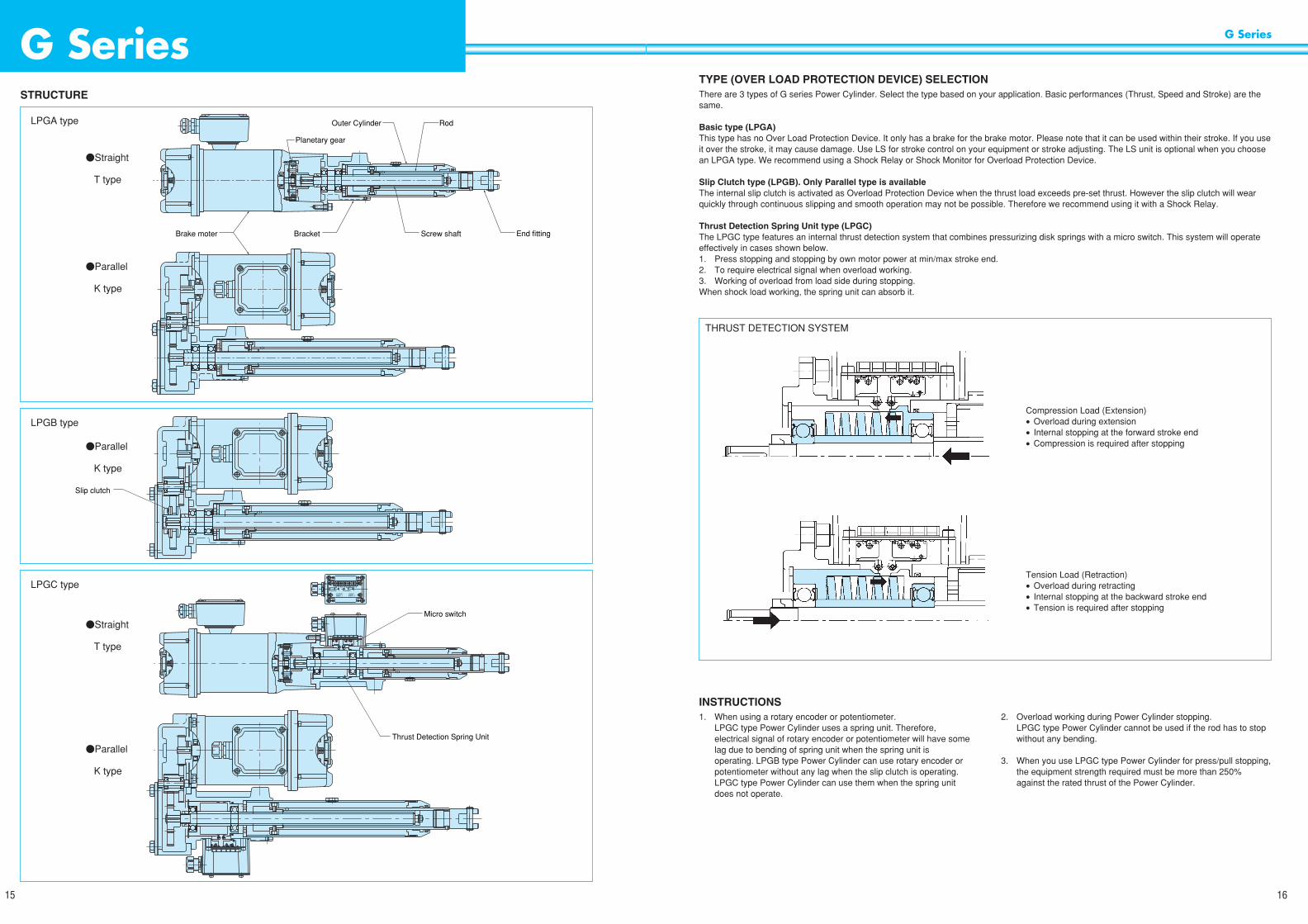
TYPE (OVER LOAD PROTECTION DEVICE) SELECTIONThere are 3 types of G series Power Cylinder. Select the type based on your application. Basic performances (Thrust, Speed and Stroke) are thesame.
Basic type (LPGA)This type has no Over Load Protection Device. It only has a brake for the brake motor. Please note that it can be used within their stroke. If you useit over the stroke, it may cause damage. Use LS for stroke control on your equipment or stroke adjusting. The LS unit is optional when you choosean LPGA type. We recommend using a Shock Relay or Shock Monitor for Overload Protection Device.
Slip Clutch type (LPGB). Only Parallel type is availableThe internal slip clutch is activated as Overload Protection Device when the thrust load exceeds pre-set thrust. However the slip clutch will wearquickly through continuous slipping and smooth operation may not be possible. Therefore we recommend using it with a Shock Relay.
Thrust Detection Spring Unit type (LPGC)The LPGC type features an internal thrust detection system that combines pressurizing disk springs with a micro switch. This system will operateeffectively in cases shown below.1. Press stopping and stopping by own motor power at min/max stroke end.2. To require electrical signal when overload working.3. Working of overload from load side during stopping.When shock load working, the spring unit can absorb it.
G Series
16
STRUCTURE
G Series
15
Brake moter Bracket Screw shaft End fitting
Rod
Planetary gear
Outer CylinderLPGA type
$Straight
T type
$Parallel
K type
$Parallel
K type
$Straight
T type
$Parallel
K type
Slip clutch
LPGB type
Micro switch
Thrust Detection Spring Unit
LPGC type
Compression Load (Extension)• Overload during extension• Internal stopping at the forward stroke end• Compression is required after stopping
Tension Load (Retraction)• Overload during retracting• Internal stopping at the backward stroke end• Tension is required after stopping
THRUST DETECTION SYSTEM
INSTRUCTIONS1. When using a rotary encoder or potentiometer.
LPGC type Power Cylinder uses a spring unit. Therefore,electrical signal of rotary encoder or potentiometer will have somelag due to bending of spring unit when the spring unit isoperating. LPGB type Power Cylinder can use rotary encoder orpotentiometer without any lag when the slip clutch is operating.LPGC type Power Cylinder can use them when the spring unitdoes not operate.
2. Overload working during Power Cylinder stopping.LPGC type Power Cylinder cannot be used if the rod has to stopwithout any bending.
3. When you use LPGC type Power Cylinder for press/pull stopping,the equipment strength required must be more than 250%against the rated thrust of the Power Cylinder.
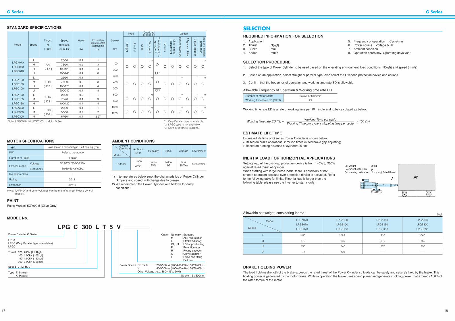
SELECTIONREQUIRED INFORMATION FOR SELECTION1. Application2. Thrust Nkgf3. Stroke mm4. Speed mm/s
5. Frequency of operation Cycle/min6. Power source Voltage & Hz7. Ambient condition8. Operation hours/day, Operating days/year
SELECTION PROCEDURE1. Select the type of Power Cylinder to be used based on the operating environment, load conditions (Nkgf) and speed (mm/s).
2. Based on an application, select straight or parallel type. Also select the Overload protection device and options.
3. Confirm that the frequency of operation and working time rate ED is allowable.
Allowable Frequency of Operation & Working time rate ED
Working time rate ED is a rate of working time per 10 minute and to be calculated as below.
ESTIMATE LIFE TIMEEstimated life time of G series Power Cylinder is shown below.• Based on brake operations: 2 million times (Need brake gap adjusting)• Based on running distance of cylinder: 25 km
INERTIA LOAD FOR HORIZONTAL APPLICATIONSSetting load of the overload protection device is from 140% to 200%against rated thrust of cylinder.When starting with large inertia loads, there is possibility of notsmooth operation because over protection device is activated. Referto the following table for limits. If inertia load is larger than thefollowing table, please use the inverter to start slowly.
Allowable car weight, considering inertia
BRAKE HOLDING POWERThe load holding strength of the brake exceeds the rated thrust of the Power Cylinder so loads can be safely and securely held by the brake. Thisholding power is generated by the motor brake. While in operation the brake uses spring power and generates holding power that exceeds 150% ofthe rated torque of the motor.
G Series
18
STANDARD SPECIFICATIONS
G Series
17
25/30
75/90
100/120
200/240
25/30
75/90
100/120
200/240
25/30
75/90
100/120
25/30
50/60
67/80
700
71.4
1.00k
102
1.50k
153
3.00k
306
0.1
0.2
0.4
0.4
0.1
0.2
0.4
0.4
0.2
0.4
0.4
0.4
0.2
0.4
1
3
4
8
1
3
4
8
1
3
4
1
2
2.67
100
200
300
400
500
600
800
1000
1200
L
M
H
U
L
M
H
U
L
M
H
L
M
H
LPGA070
LPGB070
LPGC070
LPGA100
LPGB100
LPGC100
LPGA150
LPGB150
LPGC150
LPGA300
LPGB300
LPGC300
Model Speed
Thrust
N
kgf
Speed
mm/sec.
50/60Hz
Motor
kw
Stroke
mm
Rod Travel per manual operated shaft revolution
mm
Overloadprotection OptionType
!
!
!
!
!
!
!
!
!
!
!
!
!
!
!
!
!
!
!
!
!
!
!
!
!
!
!
!
!
!
!
!
!
!
!
!
!
!
!
!
!
!
!
!
!
!
*1
*1
*3
*3
*1
*1
*1
*1
*1
*1
*1
*1
*1
*1
*2
*2
*2
*2
Clevis ad
aptor
1Type end fitting
Position sensor unit
Bellow
s
Slip
clutch
None
Parallel
Straig
ht
Rod anti–rotation
protection
LS for stroke
adjustm
ent
Thrust detection
spring
unit
Note: LPGC070H & LPGC100H : Motor 0.2kw *1. Only Parallel type is available.*2. LPGC type is not available.*3. Cannot do press stopping.
MOTOR SPECIFICATIONS AMBIENT CONDITIONS
1) In temperatures below zero, the characteristics of Power Cylinder(Ampere and speed) will change due to grease.
2) We recommend the Power Cylinder with bellows for dustyconditions.
PAINTPaint: Munsell 5GY6/0.5 (Olive Gray)
MODEL No.
Note: 400/440V and other voltages can be manufactured. Please consult Tsubaki.
Type
KW
Number of Poles
Power Source
Insulation class
Rating
Protection
Brake motor, Enclosed type, Self cooling type
Refer to the above
4 poles
30 200V /200V /220V
50Hz/ 60Hz/ 60Hz
E
30min
(IP54)
Voltage
Frequency
Ambient Conditions Ambient
temp. Humidity Shock Altitude Environment
–15°C
40°COutdoor
below85%
below1G
less1000m Outdoor Use
Model
~
Number of Motor Starts
Working Time Rate ED (%ED)
Below 10 time/min
25
Working time rate ED (%) = × 100 (%)Working Time per cycle
——————————————————————Working Time per cycle + stopping time per cycle
F m
Car weight :Coefficient of friction :Car running resistance :
m kgµF = µm <= Rated thrust
Model
Speed
L
M
H
U
1150
170
130
71
2085
280
240
102
1220
310
270
—
2060
1560
790
—
LPGA070
LPGB070
LPGC070
LPGA100
LPGB100
LPGC100
LPGA150
LPGB150
LPGC150
LPGA300
LPGB300
LPGC300
(kg)
LPG C 300 L T 5 VPower Cylinder G Series
Stroke 5 : 500mm
LPGALPGB (Only Parallel type is available)LPGC
Thrust 070: 700N 71.4kgf100: 1.00kN 102kgf150: 1.50kN 153kgf300: 3.00kN 306kgf
Type T: StraightK: Parallel
Speed (L , M, H, U)
Option No mark : StandardM : Anti-rod rotationL : Stroke adjutingK2, K4 : LS for positioningP : PotentiometerR : Rotary encoderC : Clevis adaptorI : I type end fittingJ : Bellows
Power Source No mark : 200V Class (200/200/220V, 50/60/60Hz)V : 400V Class (400/400/440V, 50/60/60Hz)Other Voltage : e.g. 380-415V, 50Hz

INSTALLATION & MAINTENANCEINSTALLATION POSITIONPower Cylinders may be installed in any position.
INSTALLATION METHODUse a trunnion or clevis mount when installing. Install with either amale (I) or female (U) style end fitting.Apply grease to the Trunnion Pin and Bracket hole.
MANUAL CONTROLTo manually adjust the stroke, remove the load from the actuator,release the brake of the brake motor then turn the manually operatedshaft of the motor with a handle.WARNING: Remove any load from the actuator rod before
releasing the brake.
Regarding rod travel per manual operated shaft revolution, pleaserefer to the table on page 17.
ANTI ROD ROTATION• For the thrust of the actuator rod there is a reaction torque.
Generally, connection to the driven load prevents rotation.• If the actuator rod end piece is required to rotate freely or if the
actuator rod is used to drive a rolling car or to pull a load with a wirerope or chain, please use option M.
SIDE LOADS ON THE RODInstall the device so that bending moments are not applied to theactuator rod. Permanent damage to Power Cylinder may result.
SETTING THE EXTERNAL STROKE ADJUST LIMITSWITCHES1. Set the limit switches taking into consideration expected coasting.
(refer to page 19)2. Set the limit switches so that the rod stops within XA dimension.3. When using the Power Cylinder for multiple driving, use the limit
switches attached on min/max stroke end of each PowerCylinder.
MAINTENANCELubricationThe Power Cylinder is delivered with grease applied to the screw andcan be used without greasing. For maintenance, recommendedgrease and lubrication cycle is as below.
Table 2 Recommended Grease
Table 3 Lubrication Cycle
BALL SCREW LUBRICANT REPLACEMENTGrease must be applied to the ball screw. Grease can be injectedthrough the grease port of the cylinder after extending the actuatorrod to the forward stroke end.
G Series
20
SELECTION 2Select the type of Power Cylinder to be used based on the following selection criteria.
1. Setting Load of Overload protection device• Slip Clutch (GB Type) : 150% ~ 200% against rated thrust• Thrust detection spring unit (GC Type) : 140% ~ 200% against rated thrust
2. Brake Holding PowerThe load holding strength of the brake exceeds the rated thrust of the Power Cylinder so loads can be safely and securely held by the brake.This holding power is generated by the motor brake. While in operation the brake uses spring power and generates holding power that exceeds150% of the rated torque of the motor.
3. Coasting and Stopping AccuracyThe position accuracy of the Power Cylinder varies depending upon speed and load inertia. Accuracy will improve as speed is lowered. Referto the table shown below, and then set the limit switches taking into consideration expected coasting.
Coasting and Stopping Accuracy Table (Reference value when time lag of relay is 0.03S)
G Series
19
MOBILUX EPNo.2
ALVANIA EP GREASE
MOBIL
SHELL
500~1000
100~500
10~200
3 to 6 months
6 to 12 months
12 to 18 months
Lubrication cycleFrequency of starts/day
Note: The above values are only for reference.
Grease Gun
Outer Cylinder
Grease Port Bolt
6.9
15.0
15.4
34.2
6.1
13.8
14.1
32.0
4.6
10.6
13.7
3.3
8.6
9.4
±0.4
±1.1
±1.4
±2.8
±0.4
±1.1
±1.4
±2.8
±0.4
±1.1
±1.4
±0.4
±0.8
±1.0
10.0
21.5
21.7
47.9
9.0
19.8
19.8
45.0
6.6
14.7
19.0
4.6
12.4
13.1
±0.5
±1.3
±1.7
±3.4
±0.5
±1.3
±1.7
±3.4
±0.5
±1.3
±1.7
±0.5
±0.9
±1.2
10.6
21.8
23.7
60.6
10.6
22.1
23.8
66.9
7.1
15.6
21.8
5.1
23.2
19.0
±0.4
±1.2
±1.5
±3.1
±0.4
±1.2
±1.5
±3.1
±0.4
±1.2
±1.6
±0.4
±0.8
±1.1
14.9
30.1
32.7
81.2
14.9
30.5
32.7
88.2
9.8
21.3
30.0
6.9
29.4
25.0
±0.5
±1.4
±1.8
±3.8
±0.5
±1.4
±1.8
±3.8
±0.5
±1.4
±1.9
±0.5
±1.0
±1.3
L
M
H
U
L
M
H
U
L
M
H
L
M
H
LPGA070
LPGB070
LPGC070
LPGA100
LPGB100
LPGC100
LPGA150
LPGB150
LPGC150
LPGA300
LPGB300
LPGC300
Model
Operation
* Values of the above table show parallel type Power Cylinder and the Power Cylinder with slip clutch when their thrust is more than 100 N. Coasting of another type of Power Cylinder will be smaller than the above.
* Coasting Distance:The amount of stroke traveled from power shut-off and until the unit completely stops.
* Stopping Accuracy:The position deviation for repeated stops. The above values include ±25% time lag of relay and brake.
Coasting Stopping accuracy Coasting Stopping accuracy Coasting Stopping accuracy Coasting Stopping accuracy
50Hz 60Hz 50Hz 60Hz
Lifting (In case of 1 and 3) Lowering (In case of 2 and 4)
(Dimensions in mm)
Note: In actual operation, rod anti-rotation provision is required.
Load
Lifting
Trunnion mount Clevis mount
Lowering
Load

POSITION SENSOR UNITIf position sensing is required, any or all of the following three built-inunits may be used only with trunnion mount.
1. Internal position sensor limit switch (2 or 4 circuit)2. Potentiometer3. Rotary encoderNote: Clevis adapter cannot be attached when a Position Sensor Unit
is used.
INTERNAL CONSTRUCTION OF POSITION SENSOR UNIT
INTERNAL WIRING OF THE POSITION LIMIT SWITCH UNITUse the internal terminal strip for the position sensor limit switch, potentiometer and rotary encoder wiring.Use shielded wire for the rotary encoder signals.
G Series
22
WIRING
BRAKE MOTOR WIRING (WITH DC BRAKE)
Note: 1. When you use separate brake power supply operation using 400V class power source, please insulate wiring from the mid-tap. In thiscase, you have to input 200V power to the DC module. If you do not have a 200V power source, use a transformer to reduce voltage to200V. Transformer capacity needs more than 90VA (from 0.1kW to 0.4kW) and please check it can be used without the voltage dropping.MCB: AC 250V, 7A minimumDC module contains a surge absorption device. Please add protection device for each contact point if necessary.
Note: 2. Do not insert a relay between the DC module and the brake coil. (Separate brake DC power supply is not available.)
* For more details, please refer to the instruction manual.
LIMIT SWITCHES SPECIFICATIONS
G Series
21
200V Class
R
M BS
T
DC Module
Pow
er Source
Pow
er Source
DM200E
B1
B2
UV
W
400V Class
R
M BS
T
DC Module
DM200E
B1
B2
UV
W
thru. mid-tap
From neutral point
Pre-wiring
200V Class
M B
DC Module
DM200E
400V Class
U
B1
B2
OCRMCF
MCR
V
WB
DC Module
DM200Ethru. mid-tap
thru. mid-tap
U
B1
B2
V
W
MCB
Pow
er Source
R
AC200V
AC200V
S
T
M
(Note 1)
Separate brake power supply
Limit Switch
Current
Contact configuration
Connection
Stroke adjustment Limit Switch (External)
D4E-1B20N (OMRON)
AC 250V 3A (cos 0 = 0.4)
M3 Screw × 3 (05.8 ~ 07.6)
Thrust detection Limit Switch
SS-5GL2D (OMRON)
AC 250V 2A (cos 0 = 0.4)
0.5mm2 × 6C Length: 1000mm Cabtire Cable
For Forward For Backward
NC
NOCOM
Red Green4
Yellow
Brown
Black
White
120
84(2
7)
Below 126
Position Sensor Unit
60
4362
PotentiometerCam Gear Head
Rotary Encoder
Terminal
SCL14B012.5~014
Micro Switch LS4
Micro Switch LS2Micro Switch LS3
Micro Switch LS1
Option
Mark
Contact
Terminal number
LS1 LS2 LS3 LS4 COM
Position Limit Switch (Internal) (K2, K4) Potentiometer
P
Rotary encoder
R
a
18
b
17
a
5
b
6
a
16
b
15
a
7
b
8
c
4
1
1
2
2
3
3
1
9
2
10
Z
11
5V
12
0V
13 14
For Power Cylinder
For Customer’s wiring
1Terminal No. 2 3 4 5 6 7 8 9 10 11 12 13 14 15 16 17 18

POTENTIO-CONTROL OPTION
STROKE DISPLAY METER
G Series
24
POSITION DETECTION UNIT SPECIFICATIONSPOSITION DETECTION INTERNAL LSUse a Position detection internal LS when there is no space to installexternal stroke adjustment LS unit, or you want to use it combinedwith a Potentiometer and/or a Rotary encoder.• When the two are attached (K2) ...The arrangement is as for micro
switches LS1 and LS2 in thedrawing on the previous page.
• When four are attached (K4) ........The arrangement is as for microswitches LS1, LS2, LS3 and LS4in the drawing on the previouspage.
LS settingsTo adjust the operating position, first operate the G series PowerCylinder, then adjust the LS cam and make the setting taking intoaccount the amount of coasting. Use a hexagonal wrench (1.5) toloosen the LS cam’s two hexagonal socket set screws and to makethe adjustment. (See the illustration on the right.)* The limit switches are not set before shipping. Upon delivery,please set them into suit your equipment.
POTENTIOMETERPotentiometer is a changeable resistor that can output electricalsignals following the stroke of the Power Cylinder.Use it combined with a Printed circuit board and Stroke displaymeter.If the actuator rod is rotated before installation, the stroke position willbe out of phase with the potentiometer.
ROTARY ENCODERThe rotary encoder is ideal for controlling the stroke in conjunctionwith a programmable controller.
ENCODER SPECIFICATIONS
G Series
23
RM-80B (DC100µA)
JIS C 1102 2.5 class
Frame/black
Full stroke 100% display
Type
Class
Appearance
Scale specifications
Center of Meter
Holes
Panel Cut
PRINTED CIRCUIT BOARDPlease adjust the meter using the ADJUST controls located on thePCB. Do not get + and – confused on the stroke meter. To have themeter display 100% when at it’s minimum value, switch terminals 1and 2 on the PCB.
200/220V50/60Hz
100/110V50/60Hz
LPCO-O
P.C.B
PI: Stroke Display Meter PotentiometerHole
R CONTROLLERThe signal from the potentiometer located inside the G series PowerCylinder position detection mechanism is digitized for display andstroke control. An internally mounted scaling mechanism can displaythe actual stroke and the degree of extension (%). Direct connectionof the R controller to the potentiometer is possible.
91.5
95
5.5
7217
.5
44.5
48
96
Panel Cut
92 +0.8–0
45+
0.6
–0
METER RELAYStroke adjustment can be easily performed from the control panel.(The steel panel attachment is standard. Please indicate if analuminum panel is desired.)
Note: When using a TC unit, etc. (4 to 20 mA output), please indicate,‘For 4 to 20 mA output.’
Meter Relay Specifications
NRP-100 (TSURUGA)
TISC1102 2.5
Black Plastic
100% at full stroke
AC100/100, 200/220V 50/60Hz
DC100µA max.
1C for both high andlow (refer to page 25)
AC250V3A (cos0=1)
Model No.
Level
External appearance
Scale specification
Power source
Input
Output contact configuration
Contact rating
1
Lower Terminal BlockTB2
Upper Terminal BlockTB1
23456789
123456789
HILO
COH+2.5V
ST/H COMbaCOMb
a
Internal Relay Contact
bCOMa
(START/HOLD)OPTIONEARTH
AC200VPOWER INPUT
LO relay contact output
AC200V
GO relay contact output
HI relay contact output
OMROND2VW-5L2A-1M
AC 250V 2A (cos0=0.4)
Model No.
Capacity
RedBlack
White
LS1, 3 LS2, 4
Yellow
Brown
Green
Micro switch specification
Contactconfiguration
Black Red
WhiteRod Backward Rod Forward
Potentiometer specification
Model No.
Maker
Total resistance
Power rating
Insulation rating
Effective electrical angle
Effective angle of rotation
CP-30
Sakae
1kΩ
0.75W
AC1000V 1min.
355° ±5°
360° Endless
Type
Manufacturer
Output method
MES-30-40
Microtech Laboratory Inc.Japan Barufu Inc.
Incremental
Output pulse number
Output wave form
Output voltage
Output resistance
Signal accuracy
Power source
Frequency response
Light source
Light receiver
40P/R
90-degree phase difference, two-phase waveform + origin output
5V Power Source “1” 4.5V min.
“0” 0.5V max.
12V Power Source “1” 11.0V min.
“0” 1.0V max.
Load resistance 2.2kΩ
Cycle error: less than 0.1 cycles
DC 5 to 12V 60mA
50kHz
Light emitting diode
Phototransistor
Operating temperature
Storage temperature
Humidity
Vibration
Shock
0°C ~ 60°C
–20°C ~ 80°C
Less than 95% relative humidity (RH), (With no condensation)
55Hz max. oscillation amplitude of 1.5mm for 2 hours in direction XYZ.
50G (X, Y, Z direction 3 times)
* Stated values are for the encoder only.
LS Cam
Set Screw
(shield)
Output circuit
Output connections
Output waveform
Mai
n cir
cuit 2.2kΩ
Output (White, Green, Yellow)
(When advancing)
Signal 1
Signal 2
Signal Z
a + b, c + d = 0.5P ± 0.125P a, b, c, d >= 0.125P
20mA maximum
OV (Black)
GND
+5 ~ +12V DCRed
Cable color
Signal 1
White Green Yellow Red Black Woven
Signal 2 Signal Z +5V OV Case
*
P
a b c d
a
1. Please use the limit switches to make the origin setting.2. External loads should not exceed allowable loss P.

REFERENCE CIRCUITS
G Series
26
The G series Power Cylinder comes equipped with a potentiometer. Use caution when installing, if the screw is turned, stroke and phase settingswill be thrown off. Using the limit switches, adjust the minimum and maximum application stroke setting before using the meter relay.
PRINTED CIRCUIT BOARDSame as the stroke meter PCB.
RELAY OPERATION (NORMALLY CLOSED CONTACT)The meter relay’s wiring is the same as that of the stroke meterexcept that a separate power supply is necessary. Please use one ofthe other power sources. Direct connection of the output contact(normally closed) with the LS stroke adjustment normally closed,contact is simple.
SHOCK RELAYWe recommend a Shock Relay as the electric safety device for GB type Power Cylinder.
ROTARY ENCODER OPTIONS
PULSE COUNTERThis counter is capable of displaying the pulse count from the rotary encoder in addition to sending relay output. With its prescale function, theactual amount of movement can also be displayed. For stroke control and other uses, please use it in conjunction with a self-protecting circuit.The display, and internal counter data, is backed up with internal batteries so that even when power is cut data is not lost.*
* If there is a power failure, counting is not possible, so do not attempt to move the jack. We recommend that external stroke adjusting limitswitches also be used.
G Series
25
Measuring needle
OFF
ON Higher (H) side relay operation
Lower limit settingindicator (L)
Upper limit settingindicator (H)
OFF Lower (H) side relay operation
ON
48
48
1006
44.8
1 2 3 4 5
6
11
7 8 9 10
12OUT1DC12V
AC100
(–) (+) DC12V ~ 24V
OUT2
Inpu
t OV
Res
et in
put
CP
2 in
put
CP
1 in
put
Key p
rotec
t inpu
t
(–)
(+)
H7CS-CW type(Two-level contact output)
MCF
M B
LS 01
R
F
S
T
NFB
LS 11 PBF PBR
OCRPBS
MCR
MCF
MCR
MCB
MCF OCR
MCRLS 02 LS 02 MCF
MCR
PL
N2
N4
N1
N3
DC ModuleDM200E
B1
UV
WB
2
Power Supply
Pow
er s
ourc
e
M1 B1
R
F
S
T
NFB
MC1R
MC1B
MC1F OCR1
PL
DC ModuleDM200E
B1
UV
WB
2
Power Supply
M2 B2
MC2R
MC2B
MC2F OCR2
DC ModuleDM200E
B1
UV
WB
2
Power Supply
Pow
er s
ourc
e
ARFPBF PBR
OCR2
ARR
OCR1PBS
ARR
ARF
MC1R
MC1F
ARF
MC1F
MC2R
MC2F
MC1F
MC1R
ARR
MC2F
ARF
MC2R
ARR
MC1R
MC2F
MC2R
LS 101
LS 112LS 212
LS 111LS 211
LS 102
LS 201
LS 202
SINGLE ACTION CIRCUITS (Separate brake power supply)
TWO MACHINES MULTIPLE DRIVE CIRCUIT (Separate brake power supply)
LS01 : Stroke adjusting LS for forwardLS02 : Stroke adjusting LS for reverseLS11 : Thrust detection LS for forwardLS12 : Thrust detection LS for reverse
LS101 : Stroke adjusting LS for forward for LP1LS102 : Stroke adjusting LS for reverse for LP1LS201 : Stroke adjusting LS for forward for LP2LS201 : Stroke adjusting LS for reverse for LP2LS111 : Thrust detection LS for forward for LP1LS112 : Thrust detection LS for reverse for LP1LS211 : Thrust detection LS for forward for LP2LS212 : Thrust detection LS for reverse for LP2
Model No.
Type
Protective construction
Prescale function
Display type
Rated voltage
Power consumption
Control output
External power supply
Operating temperature
Storage temperature
Humidity
OMRON H7CS-CW (±1 area type)
Preset counter
IP54F (panel display section)
Yes (0.001 to 99.999)
Back-lit, 7-segment LCD
AC100 to 240V (50/60Hz)
Approx. 6.6VA (at AC 250V, 50Hz)
Contact: AC 250V 3A (cos0=0.8 to 1)
DC12V ±10% 100mA (less than 5% ripple)
–10 to + 55°C (Not to be frozen)
–25 to + 65°C (Not to be frozen)
35 to 80% RH
Operation light (Specifications and dimensions are subject to change.)

G Series
28
DIMENSIONS STRAIGHT TYPE
OPTION
G Series
27
20
68
A
XA
060
.5
013
2
122.
5
102
2–0
16H
10 D
epth
1684
035
18
33 (15)
0+0.
515 0
33
010H10/d9
Cable dia. 011~013 PF1/2
92
0.1kW: 208.50.2kW: 208.50.4kW: 230.5
XB
Manual handle shaft
8
LPGA070~300 T (BASIC MODEL)0
132
122.
5
20
A
XA
060
.5
035
010H10/d9
18
33 (15)
84
102
2–0
16H
10 D
epth
16
113
96
0.5mm2×6C Length 1000mmCabtire CableCable dia. 011~013 PF1/2
92
0.1kW: 208.50.2kW: 208.50.4kW: 230.5
XB
8
0+0.
515 0
33
Manual handle shaft
Model Speed Type Stroke AMIN MAX MIN MAX LPGA LPGC
XA XB Approx. Weight (kg)
(Dimensions in mm)
L
M
H
U
L
M
H
070
100
150
300
TLPGA
LPGC
100
200
300
400
500
600
800
1000
1200
178
278
378
478
578
678
878
1078
1278
243
343
443
543
643
743
963
1183
1403
343
543
743
943
1143
1343
1763
2183
2603
65
65
65
65
65
65
85
105
125
165
265
365
465
565
665
885
1105
1325
14
15
16
18
19
20
22
24
27
18
19
21
22
23
24
26
28
31
Note: Mechanical Stroke has a room for 3 ~ 8mm at each stroke end against XA dimensions.
LPGC070~300 T (WITH THRUST DETECTION UNIT)
STROKE ADJUSTING LS
05.8~07.6
R64
3469
35563232
TRUNNION MOUNTING ADAPTOR (LPGA300-T)
1001542130
150
125
15 28
016
d9
2-012
12
BELLOWS ( -J)
010
0
I TYPE END FITTING (LPGA300-I)
33
033
150 –0.5
15
18
010H10
DIMENSIONS PARALLEL TYPE
OPTION
20
68
A
XA
060
.5
035
010H10/d9
Cable dia. 011~013 PF1/2 18
33 (15)
0+0.
515 0
33
2–0
16H
10 D
epth
16
102
122.5
120
5513
112
60
232
0.1kW: 230.50.2kW: 230.50.4kW: 252.5
XB
84
Manual handle shaft
8
LPGA070~300 K (BASIC MODEL)LPGB070~300 K (WITH SLIP CLUTCH)
102
120
A
XA
060
.5
035
010H10/d9
18
33 (15)
0+0.
515 0
33
20
232
112
60
5513 113
0.5mm2×6C Length 1000mmCabtire Cable XB
96
122.5
84
8
Manual handle shaft
2–0
16H
10 D
epth
16
Cable dia. 011~013 PF1/2
0.1kW: 230.50.2kW: 230.50.4kW: 252.5
Model Speed Type Stroke AMIN MAX MIN MAX LPGA LPGB LPGC
XA XB Approx. Weight (kg)
(Dimensions in mm)
L
M
H
U
L
M
H
070
100
150
300
K
LPGA
LPGB
LPGC
100
200
300
400
500
600
800
1000
1200
178
278
378
478
578
678
878
1078
1278
243
343
443
543
643
743
963
1183
1403
343
543
743
943
1143
1343
1763
2183
2603
65
65
65
65
65
65
85
105
125
165
265
365
465
565
665
885
1105
1325
18
19
21
22
23
24
26
28
31
18
19
21
22
23
24
26
28
31
23
24
25
26
27
28
31
33
35
Note: Mechanical Stroke has a room for 3 ~ 8mm at each stroke end against XA dimensions.
LPGC070~300 K (WITH THRUST DETECTION UNIT)
STROKE ADJUSTING LS
05.8~07.6
R64
3469
35563232
TRUNNION MOUNTINGADAPTOR (LPGA300-T)
1001542130
150
125
15 28
016
d92-012
12I TYPE END FITTING (LPGA300-I)
33
033
15
15
18
010H10
0 –0.5
CLEVIS MOUNTING ADAPTOR(LPTB500-C)
P.C.D.130016H10/d9
120
4-011
0+0.525
R25
20
12.5 12.5
40
10
BELLOWS ( -J)
010
0

G Series
30
G Series
29
VARIATION OF DIRECTION AND POSITION OF MOTOR TERMINAL BOX
DIRECTION OF MOTOR TERMINAL BOXDirection of the motor terminal box can installed as one of the four (4) directions shown below.It can be easily changed by the user.1. Remove the lid of the terminal box.2. Remove the 2 screws tightening the terminal.3. Lift the terminal without detaching the wiring to the motor and brake. Then take off the 4 screws fixing the terminal box.4. Rotate the terminal box for the required direction and fix.5. Install terminal.6. Wire the cable from the power source and replace the lid on the terminal box.When you fix the terminal box, please check that the rubber packing is inserted correctly and firmly tighten the screw.
POSITION OF MOTOR TERMINAL BOXPosition of the motor terminal box can be rotated at 90 degrees intervals as shown below.However, please do not perform this yourself. Please inform Tsubaki of the desired position when ordering.
ADJUSTMENT FOR EXTERNAL LS AND VARIATIONS OF INSTALLATION
1. STANDARD INSTALLATION
2. ADJUSTMENT METHODG series Power Cylinder has a room from 3 to 8 mm at both strokeend as mechanical stroke. However it should be used within XAdimensions. Please adjust the limit switches to operate within XAdimensions. If you operate over XA dimensions, The LS striker willcome off from LS guide rail. When you adjust limit switches, pleaseadjust and fix each limit switch to avoid lag of relative positionbetween Power Cylinder body and LS guide rail.1. Loosen set screw for LS flange (A) and LS guide rail (B).2. Slide a flange to its required position.3. Tighten the set screw for LS guide rail (B) first.4. Tighten the set screw for LS flange (A) without twist between LS
guide rail and LS rod.
3. VARIATION OF INSTALLATION
4. INSTALLATION OF EXTERNAL LS• Tsubaki has an installation manual for changing direction and quantity of LS. Please consult Tsubaki.• The direction of LS installation is free. Do not allow dust or mud on the LS guide rail for smooth operation of LS striker.
1
LS setting for standard and emergency use.
Install 3LS
Parallel
Straight
Different positionand direction
3
A C
B D
2 4
5 7
6
T Series TB type, TC type
32
Super Mini Series
31
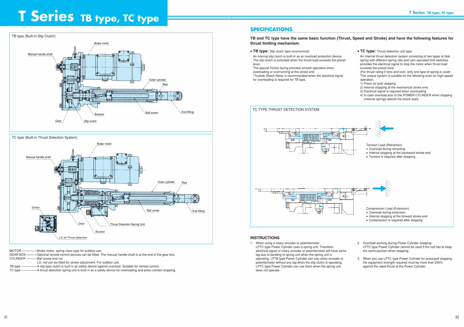
• TB type: Slip clutch type (economical)
An internal slip clutch is built-in as an overload protection device.The slip clutch is activated when the thrust load exceeds the presetlevel.The special friction facing provides smooth operation whenoverloading or overrunning at the stroke end.*Tsubaki Shock Relay is recommended when the electrical signalfor overloading is required for TB type.
• TC type: Thrust detection unit type
An internal thrust detection system consisting of two types of diskspring with different spring rate and cam operated limit switchesprovides the electrical signal to stop the motor when thrust loadexceeds the preset level.(For thrust rating 6 tons and over, only one type of spring is used)This unique system is suitable for the following even for high-speedoperation.1) Press (or pull) stopping2) Internal stopping at the mechanical stroke end3) Electrical signal is required when overloading4) In case overload acts to the POWER CYLINDER when stopping
(Internal springs absorb the shock load)
SPECIFICATIONS
TB and TC type have the same basic function (Thrust, Speed and Stroke) and have the following features forthrust limiting mechanism.
Tension Load (Retraction)• Overload during retracting• Internal stopping at the backward stroke end• Tension is required after stopping
Compression Load (Extension)• Overload during extension• Internal stopping at the forward stroke end• Compression is required after stopping
TC TYPE THRUST DETECTION SYSTEM
T Series TB type, TC type
MOTOR–––––––––Brake motor, spring close type for outdoor use.GEAR BOX ––––––Optional remote control devices can be fitted. The manual handle shaft is at the end of the gear box.CYLINDER ––––––Ball screw and nut
––––––––––––––LS. rod can be fitted for stroke adjustment. For outdoor use.TB type –––––––––A slip type clutch is built in as safety device against overload. Suitable for remote control.TC type –––––––––A thrust detection spring unit is built in as a safety device for overloading and press contact stopping.
Manual handle shaft
Brake motor
Outer cylinder
Rod
End fittingBall screwBracket
Slip clutchGear
Striker
LS. for Thrust detection
Gear
Bracket
Thrust Detection Spring Unit
Ball screw End fitting
Outer cylinder Rod
Brake motor
Manual handle shaft
TB type (Built-in Slip Clutch)
TC type (Built-in Thrust Detection System)
INSTRUCTIONS1. When using a rotary encoder or potentiometer.
LPTC type Power Cylinder uses a spring unit. Therefore,electrical signal of rotary encoder or potentiometer will have somelag due to bending of spring unit when the spring unit isoperating. LPTB type Power Cylinder can use rotary encoder orpotentiometer without any lag when the slip clutch is operating.LPTC type Power Cylinder can use them when the spring unitdoes not operate.
2. Overload working during Power Cylinder stopping.LPTC type Power Cylinder cannot be used if the rod has to keepthe same position when stopping.
3. When you use LPTC type Power Cylinder for press/pull stopping,the equipment strength required must be more than 250%against the rated thrust of the Power Cylinder.

T Series TB type, TC type
34
T Series TB type, TC type
33
TYPE SELECTION• Select the type of cylinder to be used based on the operating
environment, load condition and the following selection criteria.
SELECTION CRITERIA: TB and TC Power Cylinders have thesame basic features; thrust, speed, stroke, load, and integral motor.
The TB type is an economical, light weight, positive displacementlinear actuator with slip clutch safety protection. This actuator shouldbe considered when coupled with optional position feedback ifposition accuracy is critical.
The TC type provides thrust detection in tension and compression ofthe Power Cylinder at 150 ~ 200% of rated load without damage tothe Power Cylinder (providing that power source is coupled to thrustdetection circuit). The unique thrust detection mechanism employedalso provides for moderate shock loading of the unit without damage.This actuator should be considered for applications that may seeshock loads, require electronic overload signal, or when press/pullstopping is required. (See Table 1).
Table 1 (For high frequency use of thrust detection unit)
MODEL SELECTION1. Calculate annual running distance.
Annual Running Distance (km) =Actual Load Stroke (m) × Cycles/Day × Operating Days/Year
2. Choose a service factor based on the Power Cylinder, loadcharacteristics and the annual running distance of the PowerCylinder.
3. Multiply the thrust and the load service factors.4. Using the compensated thrust, stroke, speed and number of
cycles, select the appropriate model for your application from thestandard models.
Table 2 Service Factor
SELECTION PROCEDURE
TYPE
SPEED
TOTAL STOP CYCLES (× 104)
LPTC250-LPTC4000
M
10
S, L
30
H
5
LPTC6000-LPTC32000
M
3
S, L
10
H
1
Note: 1. When press (or pull) stopping is being used. It is recommended that you use externalwiring for the brake. (If high or medium speeds are being used, the wiring must be made separately).
2. If the values in Table 1 will be exceeded, we recommend that stopping be initiated using external limit switches.
3. When press (or pull) stopping are required, please ensure that the strength of the equipmentbeing used with the power cylinder exceeds 250% of the maximum thrust produced.
Characteristics of the load
Uniform load
Low inertia load
Medium shock
Medium inertia load
Heavy shock/with vibration
High inertia load
Application
Opening/closing for damper, valve, etc.
Opening/closing for hopper gate
Loading/unloading application, lifter, etc.
Buffer for belt conveyors
Heavily loaded cars, etc.
Annual running distance (km)
~100 km
~50 km
1.3
1.7
2.0
~50 km
~25 km
1.0
1.3
1.5
~150 km
~75 km
1.5
2.0
2.3
Note: If the running distance exceeds that listed above. Please consult Tsubaki.
Thrust (kgf)
~LP16000
LP32000
SLMH
12.5/1525/3050/60
100/120
0.10.10.20.4
LPTBLPTC
250 2502.45k 200~600
SLMH
12.5/1525/3050/60
100/120
0.10.20.40.75
LPTBLPTC
500 5004.90k 200~800
SLMH
12.5/1525/3050/60
100/120
0.20.40.751.5
LPTBLPTC
1000 10009.80k200~800
*1000
SLMH
12.5/1525/3050/6075/90
0.40.751.52.2
LPTBLPTC
2000 200019.6k200~800
*1000 *1200
SLMH
9/1125/3035/4260/72
0.751.52.23.7
LPTBLPTC
4000 400039.2k200~1200
*1500
SLMH
6.3/7.617.5/2125/3042/50
0.751.52.23.7
LPTBLPTC
6000 600058.8k500
1000*1500
SLMH
10/1220/2430/3643/52
1.52.23.75.5
LPTBLPTC
8000 800078.4k500
10001500
SLMH
10/1218.5/2230/36
2.23.75.5
LPTBLPTC
12000 12000118k500
10001500
SLMH
14.5/17.520/2431/37
3.75.57.5
LPTBLPTC
16000 16000157k
500100015002000
SLMH
10/1215/1820/24
5.57.511
LPTBLPTC
Note: 1. Separate power supply for brake is recommended for press (pull) stopping. When using the LPTC-M and LPTC-H, the brake wiring must be separated.
Note: 2. Thrust is limited for the stroke of *marked size. Refer to the dimensions table.
32000 32000314k
500100015002000
ModelThrust Speed 50/60Hz
(mm/sec.)Stroke(mm)
Motor(kW)kgfN
Brake
• 0.1 ~ 0.4 kW Motor• DC Brake• Separate power supply is available.• AC 200V is needed for DC Module input
• 0.75 ~ 11 kW motor• 3 phase AC Brake• Separate power supply is available• Same voltage as motor for AC Brake input
MOTOR SPECIFICATIONS
Brake Motor, Enclosed type, Self-cooling type4P 200V/200V/220V 50/60/60HzInsulation class E, 30 min. rating for use (IP54)
Paint: Munsell 5GY6/0.5
Ambient Conditions
Ambient temp. –15°C ~ 40°CHumidity Below 85%Shock Below 1GAltitude Less than 1000 mOutdoor use
MODEL No.
LPT B 1000 L 4 V L P C I J FT Series Power Cylinder
Bellows
Different position of Motor terminal box/L. S.
No mark: STD. End FittingI: I type End Fitting
C: Clevis Adaptor
P: Potentiometer R: Rotary Encoder
L: LS. for stroke adjusting (2pcs.)L3: LS. for stroke adjusting (3pcs.)
K2, K4: Ls. for positioning
B type or C type
Thrust
Speed: S·L·M·H
Stroke 4: 400mm
Power Source No mark 200/200/220V, 50/60/60HzV: 400/400/440V, 50/60/60Hz X: Other voltage (e.g. 380-415V 50Hz)
SPECIFICATIONS
STANDARD SPECIFICATIONS Application data:1. Power Cylinder type being considered and method of operation2. Thrust and inertia load3. Stroke4. Speed5. Frequency of use (times/minute)
6. Period of use (hours/day) and (days/year)7. Design life (years)8. Load characteristics9. Operating conditions – environmental10. Voltage and frequency of the power source
Trunnion Mounting Adaptor: Order separately from Power Cylinder

T Series TB type, TC type
36
T Series TB type, TC type
35
SELECTION EXAMPLEThe following is an example of the procedure to be followed when selecting a Power Cylinder.Application Data is required before selecting an individual Power Cylinder.Begin the Selection Process by obtaining the information required on page 32.When data is available – follow the selection procedure shown on pages 34 and 35.
APPLICATION DATA1. Type of application: Damper opening/closing (2 mid-point stops, tension and compression press stopping).
2. Required Thrust: 1,300 kgf.
3. Stroke: 600 mm (0.6m)
4. Speed: 600 mm in about 20 secs (30 mm/sec).
5. Frequency of use: 1 cycle/10 mins. (6 cycles/hr.)
6. Operating time: 10 hrs/day, 250 days/year, 5 years
7. Design life: 5 years
8. Load characteristics: Forward and reverse loading, uniform load
9. Operating conditions: Outdoors, dusty, temp. range 0°C - 35°C
10. Power: 220V, 60Hz-3PH
SELECTION OF POWER CYLINDER1. Type Selection: Press stopping with internal Limit switch.
The TC type Power Cylinder meets these requirements.
2. Select the Size of Power Cylinder:
a) Determine Service Factor: Calculate annual running distance.
× × × × = 18 km
b) Minimum thrust rating = service factor × required thrust of Power CylinderMin. Thrust Rating = 1.3 × 1300 kgf = 1690 kgf
Model Selection : LPTC 2000 L6 K2 J
3. Confirmation of Choice: Based on allowed operating frequency and total press stops.Operating Frequency
Starting frequency: <
Working time rate = ÷ (10 Min × 60 Sec/Min ) × 100% = 6.7% < 25%
Total Press Stops = × × × × 5 Years
= 15 × 104 < 30 × 104
250 Days—————
Year10 Hours
—————Day
6 Cycles—————
Hour2 Stops
—————Cycle
600mm × 2—————30mm/sec
4 times—————
Min.2 Times
—————10 Min.
250 Days—————
Yr10 Hours
—————Day
6 Cycles—————
Hour0.6 Meters—————
Stroke2 Strokes
—————Cycle
Two position Limit Switch(mid-point stops)
bellows
POWER CYLINDER
DAMPER
STOPPER
CONFIRMATION OF THE SPECIAL FEATURES1. Ensure that the frequency of use is kept below the allowable
value listed in Table 3. The allowed operating frequency dependson the starting frequency and the work rate and must be withinthe range specified in the table below. The duty cycle iscalculated with the following formula.
2. The accuracy of positioning depends upon the stopping methodemployed.
3. If multiple driving is required, refer to page 30.4. If TC Type is specified be sure total press stops do not exceed
values shown in Table 1 page 26.
Working time rate ED (%) = × 100 (%)Working Time per cycle
——————————————————————Working Time per cycle + stopping time per cycle
Table 3 Allowable Frequency of Operation
Number of motor starts
(times/min.)
Working time rate ED (%)
5
250S250L500S
4
500H1000M2000L4000S6000S
5
250M500L
1000S
4
1000H2000M4000L6000L8000S
5
250H500M1000L2000S
4
2000H4000M6000M8000L12000L
4
4000H6000H8000M12000M16000L
3
8000H12000M16000M32000L
3
16000H32000M
2
32000HModel
LPTB · LPTC
less than 25%
Note: The operating frequency is set by the motor temperature limit not the Power Cylinder. Consult factory if number of starts is greater than listed above.
INERTIA LOAD FOR HORIZONTAL APPLICATIONSSetting load of the overload protection device is from 150% to 200%against rated thrust of cylinder.When starting with large inertia loads, there is possibility of notsmooth operation because over protection device is activated. Referto Table 4 for the limits. Slow Speed Range Power Cylinders are notlimited by inertia.
* The internal thrust detection mechanisms are not user adjustableand may vary ±15%.
Car weight : mCoefficient of friction : µCar running resistance : F = µm ≤ Rated Thrust
Table 4 Allowable car weight, considering inertia
m
Allowable load/kg
L
4300
M
1500
H
850
Model
LPTBLPTC : 250
L
5500
M
2650
H
950
LPTBLPTC : 500
L
10000
M
3200
H
2200
LPTBLPTC : 1000
L
12300
M
8400
H
7100
LPTBLPTC : 2000
L
31800
M
26000
H
16800
LPTBLPTC : 4000
Allowable load/kg × 103
L
73
M
60
H
39
Model
LPTBLPTC : 6000
L
106
M
69
H
86
LPTBLPTC : 8000
L
271
M
158
H
200
LPTBLPTC : 12000
L
274
M
344
H
189
LPTBLPTC : 16000
L
368
M
761
H
860
LPTBLPTC : 32000
Note: In case of speed “S”, it is no problem practically because of slow speed.

T Series TB type, TC type
38
T Series TB type, TC type
37
MULTIPLE DRIVINGAs illustrated in Diagram 1, multiple driving is possible to distributeload in lifting and lowering operations.This arrangement results in low speed variation. When making yourselection, please use the formula to the below.
Thrust per cylinder =
Table 6 Multi-Factor
ACCURACY IN MULTIPLE DRIVINGSpeed change due to load variation is up to 5% for each PowerCylinder. The possible stopping inaccuracies are listed in Table 5,page 29.
CONTROLWhen starting, connect power to all motors at the same time.When stopping, use the limit switches attached to each device.Avoid using one limit switch to control all of the devices as error willaccumulate. (see Dia. 1)
SIDE AND ECCENTRIC LOADINGDo not apply eccentric or side loading to the cylinder.
When eccentric or side loading is present, install the device to insurethat no direct moment is applied to the cylinder rod.
INSTALLATION POSITIONPower Cylinders may be installed in any position
INSTALLATION METHOD: Use a trunnion or clevis mount wheninstalling. Install with either a male (I) or female (U) style end fitting.
Refer to the available options listed on pages 51.
MANUAL CONTROLTo manually adjust the stroke, remove the load from the actuator,release the brake of the brake motor then turn the shaft of the motorpinion on the gear box with a wrench or a socket wrench.WARNING: Remove any load from the actuator rod beforereleasing the brake.
ROD ANTI ROTATION• Accompanying the thrust of the actuator rod there is a reaction
torque. Generally, connection to the driven load prevents rotation.• If the actuator rod end piece is required to rotate freely or if the
actuator rod is used to drive a rolling car or to pull a load with a wirerope or chain please contact Tsubaki.
SIDE LOADS ON THE ROD• Install the device so that bending moments are not applied to the
actuator rod. Permanent damage to the Power Cylinder may result.
SETTING THE EXTERNAL STROKE ADJUSTMENTLIMIT SWITCHES• Refer to Table 5 page 37, then set the limit switches based on the
expected coasting.• When the full nominal stroke is to be used, set the limit switches so
that stopping occurs within the XA dimension limit taking in toconsideration coasting (XA dimension see pages 47-50).
• When multiple cylinders are to be used for driving, use limitswitches on each cylinder to control the upper and lower strokelimits.
Required thrust (kgf)———————————————————Number of Power Cylinders × Multi-Factor
INSTALLATION
Trunnion mount
Clevis mount
Diagram 2
Diagram 1
Guide roller
m
Side loading
Multiple driving
Power Cylinders being used (units)
Load Sharing Factor
2
0.8
3
0.7
4
0.6
5
0.55
6
0.5
BRAKE HOLDING POWERThe load holding strength of the brake exceeds the rated thrust of the Power Cylinder so loads can be safely and securely held by the brake. Thisholding power is generated by the motor brake. While in operation the brake uses spring power and generates holding power that exceeds 150% ofthe rated torque of the motor.Caution: Overload of TB Power Cylinder will result in loss of brake – unit may free-fall.
BRAKE STOPPINGUsing either limit switches or push button control, multiple positioning including mid-point, upper and lower point stopping are possible. Stoppingaccuracy and coasting distance depend upon the load size and drive speed. When accurate positioning is required, it is recommended that eitherlow operating speed be used or that the brake be wired separately from the motor. When setting the limit switches, please consider the over travelof the rod.(see Table 5)
COASTING AND STOPPING ACCURACYThe following chart provides coasting and stopping data for the T-Series at full load.A: Coasting Distance in mm:
The amount of stroke traveled between the power shut-off and until the unit completely stops.B: Stopping Accuracy in mm:
The position deviation for repeated stops.
Table 5 Coasting and Stopping Accuracy Table
Note: In actual operation, rod anti-rotationprovision is required.
Lifting Load Lowering LoadVertical Use
SLMH
2.24.36.9
13.7
±0.4±0.8±1.4±2.7
LPTBLPTC
250
SLMH
LPTBLPTC
500
SLMH
LPTBLPTC
1000
SLMH
LPTBLPTC
2000
SLMH
LPTBLPTC
4000
SLMH
LPTBLPTC
6000
SLMH
LPTBLPTC
8000
LMH
LPTBLPTC
12000
LMH
LPTBLPTC
16000
LMH
LPTBLPTC
32000
LiftingModel
Standard Braking (Pre-wiring)
BA
3.08.5
12.427.3
±0.6±2.1±3.2±7.3
Lowering
BA
1.93.76.0
12.5
±0.3±0.6±1.1±2.4
Lifting
Brake wired separately
BA
2.77.8
11.426.1
±0.5±1.9±2.9±6.9
2.13.66.5
12.7
±0.4±0.7±1.3±2.7
3.76.1
11.422.3
±0.9±1.6±2.9±5.9
1.83.15.9
10.2
±0.3±0.6±1.2±2.0
3.35.6
10.819.6
±0.8±1.4±2.7±5.2
1.73.26.3
15.5
±0.4±0.7±1.4±3.3
2.85.4
10.227.6
±0.7±1.4±2.6±7.7
1.52.95.0
10.4
±0.3±0.6±1.0±2.0
2.55.18.8
22.1
±0.6±1.2±2.2±6.3
1.73.27.7
13.3
±0.4±0.7±1.7±2.9
2.75.0
12.722.8
±0.7±1.3±3.4±6.4
1.52.55.28.0
±0.3±0.5±1.0±1.6
2.54.2
10.017.1
±0.6±1.0±2.7±4.9
1.23.86.4
10.9
±0.3±0.8±1.4±2.4
1.65.99.9
16.9
±0.4±1.5±2.6±4.4
0.92.53.86.6
±0.2±0.5±0.8±1.3
1.34.57.2
12.3
±0.3±1.1±1.9±3.2
0.62.74.57.6
±0.2±0.6±1.0±1.7
0.84.47.4
12.2
±0.2±1.2±2.0±3.2
0.51.82.74.6
±0.1±0.4±0.5±0.9
0.63.45.59.0
±0.1±0.9±1.5±2.4
1.93.65.68.5
±0.4±0.8±1.2±1.8
2.95.88.4
12.0
±0.7±1.6±2.1±2.8
1.32.23.45.4
±0.2±0.4±0.7±1.0
2.24.36.18.7
±0.5±1.1±1.5±2.0
2.13.55.7
±0.5±0.8±1.2
3.05.18.2
±0.8±1.3±1.9
1.32.13.6
±0.2±0.4±0.7
2.23.65.9
±0.5±0.9±1.4
2.84.16.1
±0.6±0.9±1.3
4.05.6
11.0
±1.0±1.3±3.0
1.72.63.9
±0.3±0.5±0.7
2.84.08.6
±0.7±0.9±2.4
2.13.14.3
±0.5±0.7±0.9
2.85.46.1
±0.7±1.4±1.4
1.32.02.7
±0.3±0.4±0.5
2.04.24.4
±0.4±1.1±1.0
Lowering
BA

T Series TB type, TC type
40
T Series TB type, TC type
39
REFERENCE CIRCUITS (For the motor 0.75kw and bigger)
MCF
M B
LS 01
PBS
1
R
F
S
T
U
V
W
B1
B2
B3
NFB
LS 11 2 PBF PBR
OCR
MCR
MCF
MCB
MCR
MCF OCR
MCR
MCB
LS 02 LS 12 3 PBR MCF
MCR
MCF
MCR
PL
M
(Brake pre-wired to motor)
B
U
V
W
B1
B2
B3
ARF
M1 B1
PBS
R
F
S
T
U1
V1
W1
B11
B12
B13
NFB
2
PBF PBR
OCR1
ARR
MC1F
ARF
MC1B
MC1R
MC1F OCR1
ARRARF
MC2F
MC1F
MC2R
MC1R
OCR2
PL
MC1F
LS 1011 LS 201 LS 111 MC1R
M2 B2
U2
V2
W2
B21
B22
B23
MC2B
MC2R
MC2F OCR2
3
MC1R
ARRMC1R
MC1B
MC2B
LS 102 LS 202 LS 112 MC1F
4
MC2F
ARFMC2F
LS 211 MC2R
5
MC2R
ARRMC2R
LS 212 MC2F
WIRING
BRAKE MOTOR WIRING (Pre-wiring)
For 200V Class
R
M BS
T
DC Module
DM200E
B1
B2
UV
W
For 400V Class
R
M B M BS
T
R
S
T
DC Module
DM200E
B1
B2
UV
W
thru.mid-tap
thru.mid-tap
5.5 kW and above motor with 9 lead wires.For Brake: B1, B2 and B3
For Motor: U, V, W, Z, X and YBrake lead wires are connected with U, V, W respectively.
Separate the lead wires of Brake from terminalfor quick braking circuit.
B1
U
B2V
B3
W
BALL SCREW LUBRICANT REPLACEMENTGrease must be applied to ball screw. Grease can be injectedthrough the grease port of the cylinder after extending the actuatorrod to the forward stroke end.
Recommended Grease
Lubrication Cycle for Ball Screw
GEAR BOX LUBRICATIONThe gears and bearing of the speed reducer are lubricated withgrease inside the casing.It is unnecessary to apply lubricant more than once a year. If thepower cylinder is operated constantly or left unused for long periodsof time, the grease condition should be checked.
Recommended Grease
MAINTENANCE
Ball ScrewSHELL ALVANIA EP No. 2
MOBILUX EP No. 2
SHELL
MOBIL
Gear BoxSHELL ALVANIA EP No. 1
MOBILUX EP No. 1
SHELL
MOBIL
Lubrication cycle
3 to 6 months
6 to 12 months
12 to 18 months
Frequency of starts/day
500~1000
100~500
10~100
Gear Box Grease Port
Ball Screw Grease Port
Gear Box Inspection Plate
Inspection points - Diagram 3
SBH type Brake motor 0.1 kW, 0.2 kW, 0.4 kW NB type Brake motor 0.75 kW~3.7 kW
Power Cylinder
Limit Switch
Current
Contact configuration
Connection
Stroke adjustment Limit Switch (External)
All Sizes
WLCA 2 (OMRON)
AC 250V 10A (cos 0 = 0.4)
SCS-10B (08.5 ~ 010.5) PF1/2
Thrust detection Limit Switch
LPTC 250 ~ LPTC 32000
V-165-1AR5 (OMRON)
AC 250V 10A (cos 0 = 0.4)
SCL-14A (010.5 ~ 012.5) PF1/2
Compression-Forward Tension-Reverse
NC 1
NC 2
4 NO
3 NO
Red3 Green4
Yellow 5
Brown 6
Black
White
1
2
LIMIT SWITCHES SPECIFICATIONS
200V Class
M B
DC Module
DM200E
400V Class
U
B1
B2
OCRMCF
MCR
V
WB
DC Module
DM200Ethru. mid-tap
thru. mid-tap
U
B1
B2
V
W
MCB
Pow
er Source
R
AC200V
AC200V
S
T
M
(Note 1)
Separate brake power supply
• SINGLE ACTION CIRCUITS(Separate brake power supply)
• TWO MACHINE MULTIPLE DRIVE CIRCUIT(Separate brake power supply)
Note: Please refer to the page 26 for the motor 0.4kw and smaller.

T Series TB type, TC type
42
T Series TB type, TC type
41
LIMIT SWITCHES• Two limit switches - K2• Four limit switches - K4
Operating examples of Limit Switch application
LIMIT SWITCH SET-UPTo adjust the working position of the power cylinder, adjust the camthat controls the limit switch. Adjust it by loosening the two set screwsshown in the diagram, and rotate to desired limit setting.Tighten set screws.
INTERNAL POSITION SENSOR LIMIT SWITCH
POTENTIOMETERIf the actuator rod is rotated before installation, the stroke position willbe out of phase with the potentiometer.After installation, adjust the phase correctly. The stroke may beadjusted with the external limit switches.CAUTION: Overtravel limit switches required.
POTENTIOMETER SPECIFICATIONS
K2
K4
External press stop, position sensing (extension)Fixed position stopping (retraction)
Fixed mid-position stopping, external stopping, position sensing(extension)Fixed position stopping (retraction)
Fixed mid-position stopping, external stopping, position sensingboth directions
Fixed position stopping at both ends
Press stopping at both ends, position sensing
Press stop
Fixed Position Stopping
Position Sensing
P2VW-5L2A-1M (OMRON) or equivalent
AC 250V 4A (cos 0 =0.4)
Type
Capacity
Contact configuration
1C
CP-30 or equivalent
Sakae
1 K OHM
0.75 W
AC 1000V (1 min.)
355°
360° (Infinite)
Type
Maker
Total resistance
Power rating
Insulation rating
Effective electrical angle
Effective angle of rotation
Limit Switch Cam
Set Screw
(15) P1 P3 (16)
(6) P2Rod Forward
The numbers in brackets indicate the terminals.
POSITION SENSOR UNITIf position sensing is required, any or all of the following three built-inunits may be used only with trunnion mount.1. Internal position sensor limit switch (2 or 4 circuit)2. Potentiometer3. Rotary encoder
NOTE: Clevis adapter can not be attached when a Position SensorUnit is used
POSITION CONTROL
Position Sensor Unit
POSITION SENSOR UNIT
PositionSenseUnit
POSITION SENSOR UNIT
Cam PotentiometerGear Head
Ball Screw Shaft
Rotary Encoder
Terminal
Terminals
ConnectorMicro Switches
INTERNAL CONSTRUCTION OF POSITION SENSOR UNIT

CONTROL OPTIONS
• Stroke indication meter
CIRCUIT BOARD
T Series TB type, TC type
44
T Series TB type, TC type
43
ROTARY ENCODERThe rotary encoder provides an interface to programmablecontrollers. It may be used in combination with an AC motor speedcontroller such as an inverter or servo controller to provide accuratepositioning. All Power Cylinders move 1mm/pulse.
ENCODER SPECIFICATIONSOutput method IncrementalOutput pulse number 60 Pulse/RevOutput wave form 90° phase differenceOutput voltage 12V Power Source: Above 10V
5V Power Source: Above 4VOutput resistance Above 10KΩSignal accuracy ± 1/15P ±1/4PPower source DC 4.75V ~ 13.2V 70mAFrequency response 20 kHzLight source L.E.D.Light receiver PhototransisterType SP-405Z or equivalentMaker Ono
ENVIRONMENTAL CONDITIONSOperating temperature 0°C ~ 50°CStorage temperature –20°C ~ +80°CHumidity 85% (40°C 8hrs.)Vibration 5G (X, Y, Z direction 2 hrs.)Shock 50G (X, Y, Z direction 3 times,10G
on the shaft)
SIGNAL 1
SIGNAL 2
SIGNAL Z
OUTPUT WAVE FORMS
Output Circuit Output Connection
INTERNAL WIRING OF THE POSITION LIMIT SWITCH UNITUse the internal terminal strip for the position sense limit switch, potentiometer and rotary encoder wiring.Use shielded wire for the rotary encoder signals.
1. ( ) shows Terminal No.2. Set the origin point by limit switch.3. Use load below allowable loss P.
Position Limit Switch (Internal)
Diagram 4
LS1
a1
8
b1
9
a2
1
b2
2
a3
17
b3
18
a4
10
b4
11
LS2 LS3 LS4 COM
C
7
P1
15
P2
6
P3
16
0V
12
+5V
13
Case
14
Sig 1
3
Sig 2
4
Sig Z
5
Rotary Encoder
Potentiometer
Meter Center
Hole
CIRCUIT BOARD
P1: Stroke Indication Meter Potentiometer
Black plastic
Full stroke indicated by 100%
External Apparance
Scale Specification
To adjust the meter, use the potentiometers on the printed circuit board. If you require the meter to read 100% at minimum stroke, reverse wires 1 and 2.
Model number RM-80B (DC 100µA)1.8kgΩ
1.8kgΩ
Load
Load
OVER 10kgΩ
MAX40mA
P
a
a b c d
Signal 1
Signal 2
Signal Z(Forward)
a, b, c, d = P/4 ± P/8, e = IP ± P/2
300
200
100
0–25 0 50 85 100
Allo
wab
le L
oss
P (m
W)
Ambient Temp. (°C)
Allowable Loss
Low Level Output CurrentAllowable Loss P MAX = 250mW
lot. MAX = 40mA
Signal 1 Signal 2 Signal Z +5V OV CaseBlue(3)
White(4)
Orange(5)
Red(13)
Black(12)
Mesh(14)
COMMON Load
Vcc Load
Output Wave
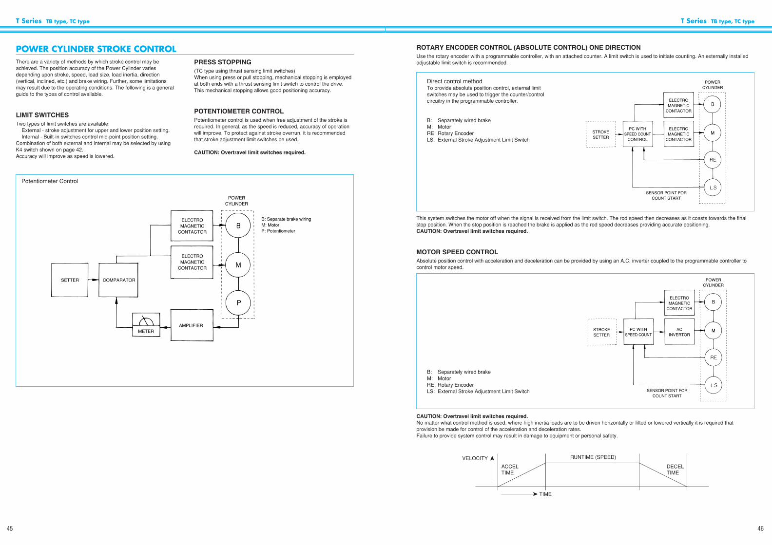
T Series TB type, TC type
46
T Series TB type, TC type
45
ROTARY ENCODER CONTROL (ABSOLUTE CONTROL) ONE DIRECTIONUse the rotary encoder with a programmable controller, with an attached counter. A limit switch is used to initiate counting. An externally installedadjustable limit switch is recommended.
This system switches the motor off when the signal is received from the limit switch. The rod speed then decreases as it coasts towards the finalstop position. When the stop position is reached the brake is applied as the rod speed decreases providing accurate positioning.CAUTION: Overtravel limit switches required.
MOTOR SPEED CONTROLAbsolute position control with acceleration and deceleration can be provided by using an A.C. inverter coupled to the programmable controller tocontrol motor speed.
CAUTION: Overtravel limit switches required.No matter what control method is used, where high inertia loads are to be driven horizontally or lifted or lowered vertically it is required thatprovision be made for control of the acceleration and deceleration rates.Failure to provide system control may result in damage to equipment or personal safety.
ELECTROMAGNETIC
CONTACTOR
ELECTROMAGNETIC
CONTACTOR
PC WITHSPEED COUNT
CONTROL
STROKESETTER
POWERCYLINDER
SENSOR POINT FORCOUNT START
Direct control methodTo provide absolute position control, external limitswitches may be used to trigger the counter/controlcircuitry in the programmable controller.
B: Separately wired brakeM: MotorRE: Rotary EncoderLS: External Stroke Adjustment Limit Switch
ELECTROMAGNETIC
CONTACTOR
ACINVERTOR
PC WITHSPEED COUNT
STROKESETTER
POWERCYLINDER
SENSOR POINT FORCOUNT START
B: Separately wired brakeM: MotorRE: Rotary EncoderLS: External Stroke Adjustment Limit Switch
RUNTIME (SPEED)
ACCELTIME
VELOCITY
TIME
DECELTIME
There are a variety of methods by which stroke control may beachieved. The position accuracy of the Power Cylinder variesdepending upon stroke, speed, load size, load inertia, direction(vertical, inclined, etc.) and brake wiring. Further, some limitationsmay result due to the operating conditions. The following is a generalguide to the types of control available.
LIMIT SWITCHESTwo types of limit switches are available:
External - stroke adjustment for upper and lower position setting.Internal - Built-in switches control mid-point position setting.
Combination of both external and internal may be selected by usingK4 switch shown on page 42.Accuracy will improve as speed is lowered.
PRESS STOPPING(TC type using thrust sensing limit switches)When using press or pull stopping, mechanical stopping is employedat both ends with a thrust sensing limit switch to control the drive.This mechanical stopping allows good positioning accuracy.
POTENTIOMETER CONTROLPotentiometer control is used when free adjustment of the stroke isrequired. In general, as the speed is reduced, accuracy of operationwill improve. To protect against stroke overrun, it is recommendedthat stroke adjustment limit switches be used.
CAUTION: Overtravel limit switches required.
POWER CYLINDER STROKE CONTROL
SETTER COMPARATOR
METERAMPLIFIER
ELECTROMAGNETIC
CONTACTOR
ELECTROMAGNETIC
CONTACTOR
POWERCYLINDER
B: Separate brake wiringM: MotorP: Potentiometer
Potentiometer Control

T Series TB type, TC type
48
T Series TB type, TC type
47
Nominalstroke A XA Min XA Max LA
Thrust
kN kgf
2.45 250
200
300
400
500
600
340
440
540
640
740
435
545
655
765
870
635
845
1055
1265
1470
161
76.5
Size
Nominal stroke 200 300 400 500
LPTB250S
LPTC250S
LPTB250L
LPTC250L
LPTB250M
LPTC250M
LPTB250H
LPTC250H
35
39
31
35
31
35
34
38
36
40
33
37
33
37
35
39
37
41
34
38
34
38
36
40
600
39
43
36
40
36
40
38
42
38
42
35
39
35
39
37
41
Nominalstroke A XA Min XA Max LA
Thrust
kN kgf
4.90 500
200
300
400
500
600
800
340
440
540
640
740
940
435
545
655
765
870
1090
635
845
1055
1265
1470
1890
161
76.5
Size
Nominal stroke 200 300 400 500
LPTB500S
LPTC500S
LPTB500L
LPTC500L
LPTB500M
LPTC500M
LPTB500H
LPTC500H
35
39
31
35
34
38
52
56
36
40
33
37
35
39
53
57
37
41
34
38
36
40
55
59
600
39
43
36
40
38
42
57
61
800
42
46
39
43
40
44
59
63
38
42
35
39
37
41
56
60
Nominalstroke A XA Min XA Max LA
Thrust
kN kgf
9.80 1000
7.84 800
200
300
400
500
600
800
1000
360
460
560
660
760
960
1160
465
575
685
795
900
1120
1340
665
875
1085
1295
1500
1920
2340
161
76.5
Size
Nominal stroke 200 300 400 500
LPTB1000S
LPTC1000S
LPTB1000L
LPTC1000L
LPTB1000M
LPTC1000M
LPTB1000H
LPTC1000H
42
48
40
46
56
62
62
68
44
50
42
48
58
64
64
70
45
51
44
50
60
66
66
72
600
49
55
47
53
63
69
69
75
800
52
58
51
57
67
73
73
79
1000
56
62
54
60
70
76
76
82
47
53
45
51
62
68
67
73
Nominalstroke A XA Min XA Max LA
Thrust
kN kgf
19.6 2000
15.7
12.3
1600
1250
200
300
400
500
600
800
1000
1200
400
500
600
700
800
1000
1200
1400
520
630
740
850
955
1175
1395
1615
720
930
1140
1350
1555
1975
2395
2815
164
79
Size
Nominal stroke 200 300 400 500
LPTB2000S
LPTC2000S
LPTB2000L
LPTC2000L
LPTB2000M
LPTC2000M
LPTB2000H
LPTC2000H
56
64
65
73
71
79
91
99
58
66
67
75
73
81
93
101
60
68
69
77
75
83
95
103
600
65
73
73
81
79
87
99
107
800
69
77
77
85
83
91
103
111
1000
73
81
81
89
87
95
107
115
1200
77
85
85
93
91
99
111
119
63
71
71
79
77
85
97
105
Nominalstroke A XA Min XA Max LA
Thrust
kN kgf
39.2 4000
33.3 3400
200
300
400
500
600
800
1000
1200
1500
440
550
650
750
850
1050
1250
1450
1750
585
695
805
910
1020
1235
1450
1670
1995
785
995
1205
1410
1620
2035
2450
2870
3495
182
97.5
Size
Nominal stroke 200 300 400 500
LPTB4000S
LPTC4000S
LPTB4000L
LPTC4000L
LPTB4000M
LPTC4000M
LPTB4000H
LPTC4000H
100
115
99
114
118
133
137
152
104
119
102
117
122
137
140
155
107
122
106
121
126
141
144
159
600
114
129
112
127
133
148
151
166
800
121
136
116
131
140
155
158
173
1000
128
143
126
141
146
161
165
180
1200
135
130
133
148
153
168
172
187
1500
146
161
144
159
164
179
182
197
111
126
109
124
129
144
147
162
LPT250
LPT500
LPT1000
LPT2000
LPT4000
Approx. Weight (kg)SPECIFICATIONS/DIMENSIONS
LPT BC 250 to 4000
DIMENSIONS
Shaft forHandle
LS. for Stroke Adjusting
Lub. Plug
0F
T1H
10 D
epth
EE
(Bot
h si
des)
KD
LPTB type
016
H10
Dep
th 2
7Shaft forHandle
LS. for Stroke Adjusting
Lub. Plug
(Bot
h si
des)
KD
0F
T1H
10 D
epth
EE
(Bot
h si
des)
LPTC type For LPTC250
SizeSpeed
mm/sec.50/60Hz
Motorkw
12.5/1525/3050/60
100/120
LPT250SLMH
0.1
0.20.4
90
B1
40(125)
B2
15
C
130
F
—
—
S
60
AH
125
BH
287
TH
—(101)
LB
120
AB
73
BB
130
TB
35
Q
58
R
Length Height Width Cylinder
12.5/1525/3050/60
100/120
LPT500SLMH
0.10.20.4
0.75
90 40(125)
15 130
65
—
20
60 125 287
70 150 327
—(101)
120
140
73130 35 58
12.5/1525/3050/60
100/120
LPT1000SLMH
0.20.4
0.751.5
90 50(145)
15 130
65—
2070 150 327 —
(107) 140 — 150 40 70
12.5/1525/3050/6075/90
LPT2000SLMH
0.40.751.52.2
105 50(165)
16 145
70
—
20
85 165 367 —(110) 170 — 180 50 76
9/1125/3035/4260/72
LPT4000SLMH
0.751.52.23.7
130 50(195)
18 170
90—
20100 195 446 —
(127) 200 — 220 70 95
Size
LPT250SLMH
16
FT1
27
EE
36
E
16
FT2
OA-W1613(011~13)
KD
12
SH
Trunnion End fitting Motor Handle
LPT500SLMH
16 27 36 16 A20C
A20C
12
LPT1000SLMH
20 32 40 20 12
LPT2000SLMH
25 37 50 25A20C
A25C
12
LPT4000SLMH
32 45 70 32
25
GT
12.5
HT
18
JT
25
25 12.5 18 25
30 15 20 30
35 17.5 25 40
40 20 35 50
KT
35
L
69
LT
35 69
45 82
60 99
75 115A20C
A25C12
123
KL
123
159172123159172190159172190201
132
123 132
MD
132
186
132
186
230
186
230255
296
231
253
ML
231
253374231253374439253374439481374439481524
120
MH
120
170
120
170
120
170
200
170
200

T Series TB type, TC type
50
T Series TB type, TC type
49
Nominalstroke A XA Min XA Max
500
1000
1500
855
1355
1955
1010
1560
2210
1510
2560
3710
Size
Nominal stroke 500 1000
LPTB6000S
LPTC6000S
LPTB6000L
LPTC6000L
LPTB6000M
LPTC6000M
LPTB6000H
LPTC6000H
153
175
163
185
178
200
193
220
1500
203
225
213
225
228
250
243
265
178
198
188
210
203
223
218
238
Nominalstroke A XA Min XA Max
500
1000
1500
900
1400
1900
1065
1615
2165
1565
2615
3665
Size
Nominal stroke 500 1000
LPTB8000S
LPTC8000S
LPTB8000L
LPTC8000L
LPTB8000M
LPTC8000M
LPTB8000H
LPTC8000H
236
266
233
263
251
281
286
316
1500
298
328
293
323
312
342
346
376
267
297
263
293
281
311
316
346
Nominalstroke A XA Min XA Max
500
1000
1500
2000
950
1450
1950
2450
1135
1685
2235
2785
1635
2685
3735
4785
Size
Nominal stroke 500 1000
LPTB12000L
LPTC12000L
LPTB12000M
LPTC12000M
LPTB12000H
LPTC12000H
291
330
306
345
340
379
1500
375
414
389
428
422
461
2000
417
456
432
471
455
504
333
372
348
387
382
421
Nominalstroke A XA Min XA Max
500
1000
1500
2000
1060
1560
2060
2560
1260
1810
2360
2910
1760
2810
3860
4910
Size
Nominal stroke 500 1000
LPTB16000L
LPTC16000L
LPTB16000M
LPTC16000M
LPTB16000H
LPTC16000H
490
539
525
574
535
584
1500
602
651
637
686
647
696
2000
657
706
693
742
705
754
546
595
581
630
591
640
Nominalstroke A XA Min XA Max
500
1000
1500
2000
1315
1815
2315
2815
1575
2125
2675
3225
2075
3125
4175
5225
Size
Nominal stroke 500 1000
LPTB32000L
LPTC32000L
LPTB32000M
LPTC32000M
LPTB32000H
LPTC32000H
1260
1350
1270
1360
1308
1398
1500
1455
1545
1465
1555
1503
1593
2000
1556
1646
1566
1646
1604
1694
1358
1448
1368
1458
1406
1496
LPT6000
LPT8000
LPT12000
LPT16000
LPT32000
Approx. Weight (kg)
DIMENSIONS for LPT6000 ~ LPT32000
LPT6000 ~ LPT32000
LS. for Stroke AdjustingLube Plug
Lube Plug
Lube Plug
0F
T1H
10-F
EL
(Bot
h si
des)
0FT2H10
0Q
0R
1
AB
TB
KD
KL
L JT
LT 0 –1
A
XAC B1 B2
MD
SH
M
F1 F2 ML
Shaft forHandle
LS. for Stroke AdjustingLube Plug
Lube Plug
Lube Plug
0F
T1H
10-F
EL
(Bot
h si
des)
0FT2H10
0Q0R
1
AB
TB
KD
KL
L JT
LT 0 –1
A
XAC B1 B2
MD
SH
MF1 F2 ML
Shaft forHandle
Speed50/60Hz
Motorkw
6.3/7.617.5/2125/3042/50
LPT6000SLMH
0.751.52.23.7
145
B1
60(155)
B2
20
C
50
F1 F2
120
AH
230
BH
160
IH
240
AB
260
TB
80
Q
115
R
Length Height Width
Cylinder
10/1220/2430/3643/52
LPT8000SLMH
1.52.23.75.5
175 65(165)
25 50 150 280 175 310300
95 130
10/1218.5/2230/36
LPT12000LMH
2.23.75.5
175 75(175)
25 50 150 280 175 300 350
110 160
14.5/17.520/2431/37
LPT16000LMH
3.75.57.5
220 90(180)
32 50 180 329 162 360 400
130 180
10/1215/1820/24
LPT32000LMH
5.57.511
280 130(285)
42 85
125
145
145
175
190 260 590 275
450
TH
540
540
609
1025
—
LB
—
—
—
— 520 540
180 240
LPT6000SLMH
40
FT1
55
EE
40
FT2
A20CA20CA25CA25C
KD
16
Z
Trunnion End fitting Motor Other
LPT8000SLMH
45 60 45
A20C
A25C
A25C
A25C
16
LPT12000LMH
50 70 50 16
LPT16000LMH
63 75 63 20
LPT32000LLH
90 110 90
40
JT
65
45 70
55 90
65 100
90 140
L
45
LT
50
65
80
125A25C
A30B30
17
SH
17
17
24
27
KL MD159162190201162190201229190201229201229229
229
263
186186230255186230255304230255304255304304
461436501544573481524616626669761669761799591629731
304
324
ML
LPTB type
LPTC type

52
Ultra Heavy Duty SeriesT Series TB type, TC type
51
OPTIONS
CLEVIS MOUNTING ADAPTOR CLEVIS MOUNTING ADAPTOR (mm)
TRUNNION MOUNTING ADAPTOR (mm)TRUNNION MOUNTING ADAPTOR
LPTB500-C
LPT250SLMH
LPT500SLM
LPT1000SLMH
LPT2000LPT4000LPT6000
8000120001600032000
LPT500H
Power CylinderSize
Size No. ofClevis B C E F G H J K
max. NL
120 12.5 25 20 40 10 130 R25 1116
LPTB1000-C 140 15 30 25 40 12 140 R31 1120
LPTB2000-CLPTB4000-CLPTB6000-CLPTB8000-CLPTB12000-CLPTB16000-CLPTB32000-C
170200240300300360520
17.520
22.525
32.54065
354045506580125
304050556070100
557085100120145240
15202225273040
170210240300300360520
R36R47—————
14181818222226
25324045506390
LPTB500-T
LPT250SLMH
LPT500SLM
LPT1000SLMH
LPT2000SLMH
LPT4000SLMH
LPT500H
Power CylinderSize
Size No. ofTrunnion AY BY FY FT HY K M N ZR
130 180 15 16 150 52 40 25 1825
LPTB6000-TLPTB8000-TLPTB12000-TLPTB16000-TLPTB32000-T
LPT60008000120001600032000
Size No. ofTrunnion AY BY FY H HY
Trunnion Mounting Adaptor
Z FT KM1
M2N
220250280320400
280320360400500
2225273035
290335360450420
240280300380320
2227333345
4045506390
160185195210275
70808590
120
3035404050
R
55607075
110
LPTB1000-T 130 180 15 20 150 45 40 25 1830
LPTB2000-T 150 200 15 25 170 45 40 25 1835
LPTB4000-T 180 240 20 32 170 55 50 30 2245
BELLOWS (mm) END FITTING
END FITTING (mm)
BELLOWS
LPT500 and belowLPT1000LPT2000LPT4000LPT6000LPT8000LPT12000LPT16000LPT32000
LPT250LPT500
LPT1000LPT2000LPT4000
DModel No.
A CB
909090120135150180210250
35
456075
18
202535
25
304050
D
25
303540
F4-0N
2-0N
LPT250
LPT4000
G
H
MAX K
0L H10/d9
0L H10/d9
0J
0J
B
B
C E C
+0.50
E CC+1.0
0
~
LPT6000
LPT32000
~
HGF
HY
HY H
FYFY
RK
K
MN
N RM1 M2
0FT
d9
0FT
d9
2-0Z
4-0Z
BYAY
BYAY
I typeA
B C
D0 –0.5
0D
AVAILABLE DESIGN RANGEPlease supply us your requirement including application, duty cycle,actual thrust force, speed, stroke and atmosphere. We will design thebest matched Power Cylinder for you.
LMH
LP63000 7.5/910/1215/18
1000~300063000
LM
L
LP90000 7.5/910/12
1000~300090000
LP125000 7.5/9 1000~3000125000
ModelSpeed mm/sec
50/60HzThrust(kgf)
Stroke(mm)
30°30°
30° 30°
8–M36Depth 45
058
0
515
622
1238
19
743
026
0
320
52
160
130200
270
670
640
216
A15C
A25C
0125 (H10)Depth 150
0300
035
0
035
0
2115
Min. 2500
0125 (H10)
30°30°
30° 30°
8–M42Depth 50
066
0
610
3230
Min. 3730
775
1357
27
812
028
0
370
55
190
150224
314
770
740
263
A15C
B30C
0150 (H10)Depth 175
0350
038
0
038
0
0150 (H10)
Example of dimension:Size: LPT63000L10
Example of dimension:Size: LPT90000M20

Multi Series
54
Multi Series
53
CYLINDER• Ball screws convert rotary motion into linear motion. Cylinder stroke can be adjusted by an externally mounted limit switch.• Limit switches for outdoor use are available.• Bellows are available for additional protection for outdoor use.• Integral dust seal for cylinder rod is rated for outdoor use.
GEAR BOX• Heat treated spiral bevel gears for tough dependable performance.• Cradle movement is also possible with multiple cylinder operation.• Low Maintenance.• Leak Proof
Trunnion mountLube port
End fitting
SealBracket
Ball screwRod
Outer cylinder
Ball nut
Collar
Bearing
Sliding bushing
BearingInput shaftHousing
Trunnion mountLimit switch Lube port
End fitting
SealBracket
Ball screwRod
Outer cylinder
Ball nut
Collar
Thrust Detection Unit
Sliding bushingBearing
Input shaftHousing
LPTB type
LPTC type
LPTB and LPTC FEATURESTB Type Features• Economical ball screw drive.• Light weight and compact.• During stopping, rod position is kept stationary by driver source brake.
TC Type Features• Press-loaded stopping, stroke and self-stopping (Consult Tsubaki).• Electrical overload indication (optional).• When Power Cylinder is stopped, this mechanism allows absorption of shock or overload from driven side.
THRUST LIMITING MECHANISM AVAILABLE – TC TYPEThe TC Power Cylinder utilizes an internal thrust detection system. This unique system is employed to detect thrust loading-providing electricalfeed back that allows press/pull stopping. Two types of disk springs with different spring rates are coupled with cam operated limit switches, whichresult in a system that will allow press stopping during high speed operation in both tension and compression of the Power Cylinder.(For thrust ratings in excess of 6 tons only one type of spring is used.)
Tension Load (Retraction)Limit switch operation: When a load of 150%* of thecylinder rated capacity is reached, the internaltension limit switch is activated.
Compression Load (Extension)Limit switch operation: When an overload of 150%*of the cylinder capacity is reached, the internalcompression limit switch is activated.
* The internal thrust detection mechanisms are not user adjustable and may vary ±15%

Multi Series
56
Multi Series
55
STANDARD SPECIFICATIONS
AMBIENT CONDITIONS
Paint: Munsell 5GY 6/0.5
MODEL NUMBER AND ORDERING EXPLANATION
Model
Thrust
Screw lead
Gear ratio
Overall efficiency
No-load idling torque
Holding torque
Allowable input shaft torque (Note 1.)
Necessary input torque per
basic capacity (Note 2.)
Screw movement per input shaft revolution
Maximum input shaft rpm
Screw shaft rotational torque at
the basic capacity
Stroke
LPT500B
4.90
500
6
2
85.5
0.74
0.075
1.78
0.18
11.0
1.12
2.74
0.28
3
2400
1200
5.20
0.53
200, 300
400, 500
600, 800
LPT1000B
9.80
1000
8
2
85.5
2.06
0.21
4.74
0.48
29.3
2.99
7.32
0.75
4
1800
900
13.9
1.41
200, 300
400, 500
600, 800
LPT2000B
19.6
2000
10
2
85.5
5.19
0.53
11.9
1.21
73.2
7.47
18.3
1.87
5
1080
720
34.7
3.54
200, 300
400, 500
600, 800
LPT4000B
39.2
4000
12
2
85.5
14.7
1.5
28.4
2.90
176
17.9
43.9
4.48
6
720
420
83.2
8.49
200, 300
400, 500
600, 800
1000, 1200
LPT6000B
58.8
6000
12
2
85.5
23.5
2.4
42.7
4.35
264
26.9
65.9
6.73
6
500
300
125
12.7
500
1000
1500
LPT8000B
78.4
8000
16
2
85.5
108
11
75.9
7.74
471
48.1
118
12.0
8
382.5
270
222
22.6
500
1000
1500
LPT12000B
118
12000
16
2
85.5
160
16.3
114
11.6
353
36.1
177
18.0
8
255
165
333
34.0
500
1000
1500
2000
LPT16000B
157
16000
24
2
85.5
331
33.8
228
23.2
707
72.2
354
36.1
12
180
120
665
67.9
500
1000
1500
2000
LPT32000B
314
32000
24
2
85.5
624
63.7
455
46.4
1413
144.2
707
72.1
12
120
90
1331
136
500
1000
1500
2000
kN
kgf
mm
%
N·cm
kgf·cm
N·m
kgf·m
N·m
kgf·m
N·m
kgf·m
mm
N·m
kgf·m
mm
LPTB
LPTCr/min
Note: 1. Allowable torque of input shaft only. (Please confirm when link operation.)2. This torque are including no-load idling torque.
Temperature Shock
–20°C ~ 80°C Less Than 3GOutdoor Use
Note: 1. These ambient conditions apply only to the main body of the cylinder, the motor or other optional parts may have varying requirements.2. Bellows are recommended for dirty or dusty surroundings.3. For use near the sea, modified paint and limit switches are available and recommended for proper protection against corrosion.
LPT B 1000 B R 6 L I JPower Cylinder Multi-Series
Bellows
No mark = STD. End fittingI = Male Clevis End fitting
L = Rod Limit switches
Stroke: 6 = 600mm
B type (No thrust detector)C type (Thrust detector)
Thrust: 1000kg
Bevel gear type
Relation of input shaft rotation and rod movement (see below)
R type L type
REQUIRED ORDER INFORMATION1. Type2. Thrust and inertia load (kgf)3. Stroke (mm)4. Speed (mm/sec.)
5. Frequency of starts (times/min.)6. Operational hours per day and annual running days7. Load characteristics8. Ambient conditions
SELECTION PROCEDURE1. Decide what type of cylinder is needed for the application, LPTB
or LPTC.
2. Choose the service factor from the table.
3. Calculate annual running distance using stroke, frequency of use,working hours.
Annual running distance (km) = Stroke under load (m) × Frequency of starts (time/day)
× Working days (days/year) × 10–3
4. When load varies during operation, calculate equivalent load asfollows;
PM =
5. For synchronous operation determine “Multi-Factor” from table.
6. Calculate Equivalent Load = Thrust × Service Factor × Multi-Factor
Service Factor
Multi Factor
7. Select the type of cylinder from calculated equivalent load andstroke required.
8. Check life of cylinder by comparing annual running distance withload life chart.
Life is based on B10 life of ball screw.
PMin + (2 × PMax)—————————
3PM = Equivalent load (kgf)PMin = Minimum load (kgf)PMax = Maximum load (kgf)
Characteristics Typical application SF
Uniform/no shockLow inertia
Light shockMedium inertia
Heavy shock,Vibration
Opening/Closing damper, valve
Opening/closing hopper gateLoading, unloading lifter
Buffer for belt conveyer, Heavily loaded car.
1
1.2
1.52
Number of units 6
1.50
5
1.25
4
1.0
3
1.0
2
1.0Multi factor
Please consult Tsubaki when more than six units are required.
20
0.5
1
2
4
6
8
12
16
32
LPTB, LPTC32000
LPTB, LPTC16000
LPTB, LPTC12000LPTB, LPTC8000
LPTB, LPTC6000
LPTB, LPTC4000
LPTB, LPTC2000
LPTB, LPTC1000
LPTB, LPTC500
1000800600400200100806040
Load(Ton)
Load-Life Chart
Life in running distance (km)
MULTI- SERIES POWER CYLINDER SELECTION
MOTOR SELECTIONVarious types of motors may be used, (a brake is necessary due to the high efficiency of the ball screw) power-off type brakes arerecommended, and the torque of the brake should exceed 150% of the required for the load.
Motor capacity is calculated as follows:
kw = Motor capacity (kw)P = Driven load (kgf)V = Velocity (m/s)η = Cylinder efficiency (η = 0.85)
(at rated thrust)
Efficiency of other elements, such as gear reducers, must alsobe taken into consideration.
Note:1. If motor is larger than required, it will cause damage to the
cylinder.2. The brake must be connected to the power source
separately from the motor.
kw = P × V———102 × η

Multi Series
58
Multi Series
57
MAINTENANCE
BALL SCREW LUBRICANT REPLACEMENTGrease must be applied to ball screw. Grease can be injectedthrough the grease port of the cylinder after extending the actuatorrod to the forward stroke end.
Recommended Grease
Lubrication Cycle for Ball Screw
GEAR BOX LUBRICATIONGears and bearings are pre-lubricated with grease, and require noadditional maintenance. After long term operation or storage, greasequality may deteriorate. Unit should be checked and additionalgrease added if necessary.
Recommended Grease
Ball screwSHELL
MOBIL
SHELL ALVANIA EP No. 2
MOBILUX EP No. 2
500~1000
100~500
10~100
3 to 6 months
6 to 12 months
12 to 18 months
Frequency of starts/day Lubrication Cycle
Gear boxSHELL
MOBIL
SHELL ALVANIA EP No. 1
MOBILUX EP No. 1
WIRING
An example wiring diagram is shown here.For reference only.All Limit Switches in series.
LIMIT SWITCHES SPECIFICATIONS
MCF
M B
LS 01
PBS
R
F
S
T
U
V
W
B1
B2
B3
NFB
LS 03 LS 05 LS 11 2 PBF PBR
OCR
MCR
MCF
MCB
MCR
MCF OCR
MCR
MCB
LS 02 LS 04 LS 06 LS 12 3 MCF
MCR
MCF
MCR
PL
1
LS01, LS03, LS05; FORWARD STROKE LIMIT SWITCHESLS02, LS04, LS06; REVERSE STROKE LIMIT SWITCHES
LS11, LS12; EXTERNAL STROKE ADJUSTMENT LIMITSWITCHES
Power Cylinder
Limit switch
Current
Contact configuration
Connection
Stroke adjustment Limit Switch (External)
All Sizes
WLCA 2 (OMRON)
AC 250V 10A (cos 0 = 0.4)
SCS-10B (08.5 ~ 010.5) PF1/2
Thrust detection Limit Switch
LPTC 250 ~ LPTC 32000
V-165-1AR5 (OMRON)
AC 250V 10A (cos 0 = 0.4)
SCL-14A (010.5 ~ 012.5) PF1/2
Forward Reverse
NC 1
NC 2
4 NO
3 NO
Red3 Green4
Yellow 5
Brown 6
Black
White
1
2
Ball Screw Lube Port
Lube Port Gear Box
APPLICATION INFORMATION
1. SYNCHRONOUS OPERATIONThe Multi-cylinder allows synchronous operation of several units.The above diagrams illustrate some possible installation options.
2. OVERLOAD PROTECTIONWhen a LPTB type is used, a torque limiter coupling isrecommended on the motor output shaft to protect againstoverload. A torque limiter coupling is not necessary for the LPTCtype, however thrust detectors for each Power Cylinder must beindividually wired to the power source, separate from the motor.
3. STROKE ADJUSTMENTStroke is limited by external limit switches at both ends. Limitswitches are available for mounting to Power Cylinder body. Rod“coasting” distance must be considered when determining properpositioning of limit switches. All upper and lower limit switchesmust be wired in series.
4. ROD ROTATION REACTION TORQUEThe thrust of the actuator rod creates a reaction torque.Generally, connection to the driven load prevents rotation. If theactuator rod end piece is required to rotate freely or if theactuator rod is used to drive a rolling car or to pull a load with awire rope or chain, please contact Tsubaki.
5. THRUST DETECTORPreset thrust detector setting of LPTC Series Power Cylinder is150% of rated thrust and the safety device does not operateduring normal turning, inclining and lifting motion starts.However, in applications with a heavy load or vehicle, the safetydevice may be triggered during starting or cutting off operation.Please consult Tsubaki.
6. ALIGNMENTProper alignment of trunnion and rod end centers is veryimportant, and care must be taken to ensure it is done correctly.A side load must not be applied to the cylinder duringoperation.
7. FLOATING SHAFTLong floating shafts may induce vibration. Shaft rigidity andbacklash of coupling must be carefully checked.
8. COUPLINGChain, gear, and flange type couplings are recommended forconnecting input shaft.
9. OVERHUNG LOAD (O.H.L)Be sure that overhung load is below the limit (Table 1) beforeinstalling gears, sprockets and pulleys on a shaft.
Drive Factor: f
O.H.L (kgf):T = Torque (kgf·m)f = Drive factorLf = Load position factorR = Radius of sprockets, gears, V-pulleys etc.
R = Distance of load positionQ = Shaft length
Allowable O.H.L. T × f × LfR
>=
1.00
1.25
1.50
2.50
Chain sprocket
Gear
V-belt pulley
Flat-belt pulley
Q
R
Table 1 Allowable overhung load Load position factor: Lf
500
56
Size - LPTB, TC
Allowable O.H.L. (kgf)
1000
108
2000
199
4000
356
6000
469
8000
689
12000
903
16000
1430
32000
2280
0.25
0.8
R/Q
Lf
0.38
0.90
0.5
1.0
0.75
1.50
1
2
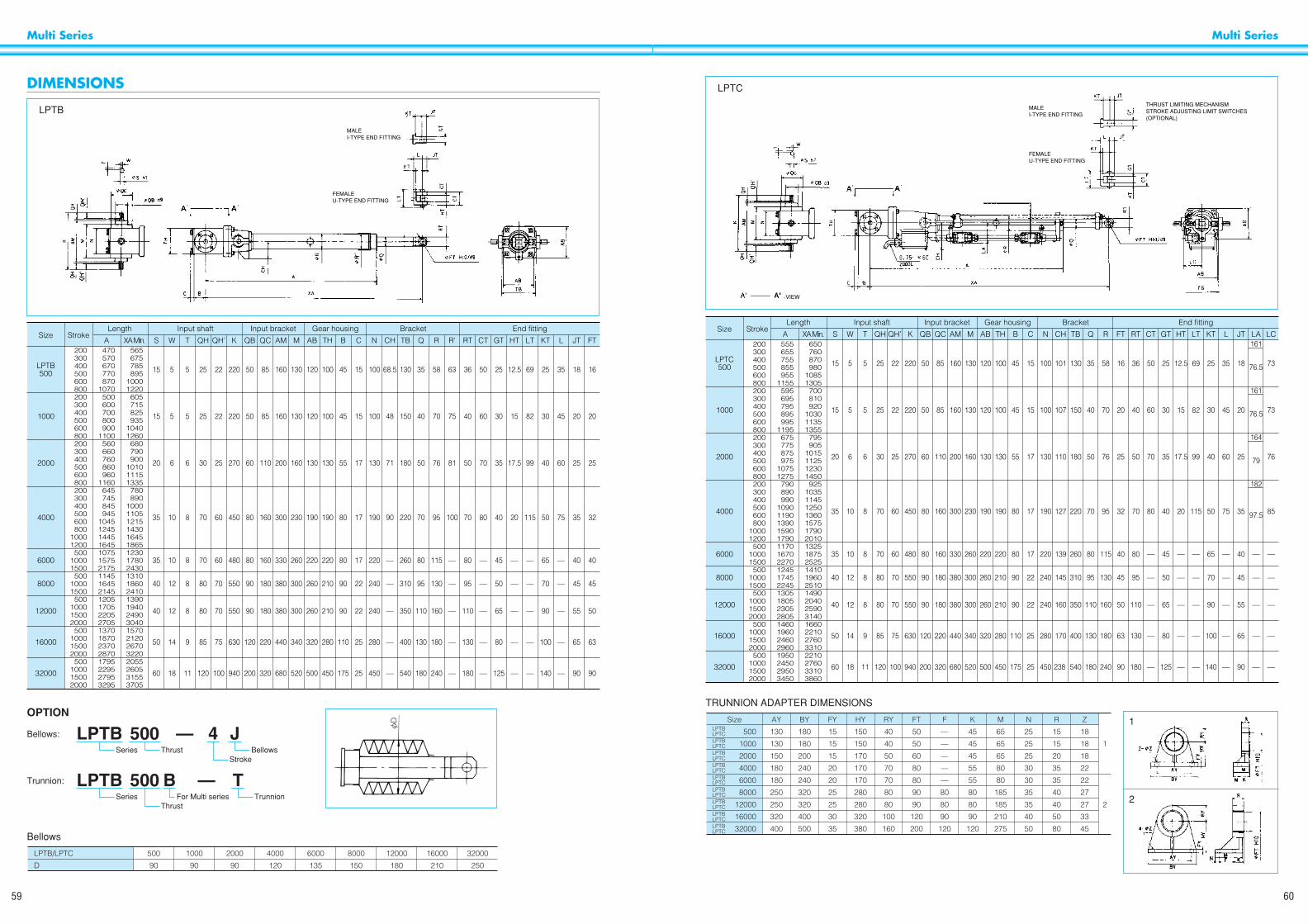
Multi Series
60
Multi Series
59
MALEI-TYPE END FITTING
THRUST LIMITING MECHANISMSTROKE ADJUSTING LIMIT SWITCHES(OPTIONAL)
FEMALEU-TYPE END FITTING
-VIEW
LPTC
Size Stroke
650760870980
10851305700810920
103011351355795905
1015112512301450925
1035114512501360157517902010132518752525141019602510149020402590314016602210276033102210276033103860
555655755855955
1155595695795895995
1195675775875975
10751275790890990
10901190139015901790117016702270124517452245130518052305280514601960246029601950245029503450
200300400500600800200300400500600800200300400500600800200300400500600800
10001200
50010001500
50010001500
500100015002000
500100015002000
500100015002000
161
76.5
161
76.5
164
79
182
97.5
—
—
—
—
—
LA
73
73
76
85
—
—
—
—
—
LC
16
20
25
32
40
45
50
63
90
FT
18
20
25
35
40
45
55
65
90
JT
35
45
60
75
—
—
—
—
—
L
25
30
40
50
65
70
90
100
140
KT
69
82
99
115
—
—
—
—
—
LT
12.5
15
17.5
20
—
—
—
—
—
HT
25
30
35
40
45
50
65
80
125
GT
50
60
70
80
—
—
—
—
—
CT
58
70
76
95
115
130
160
180
240
R
35
40
50
70
80
95
110
130
180
Q
130
150
180
220
260
310
350
400
540
TB
101
107
110
127
139
145
160
170
238
CH
15
15
17
17
17
22
22
25
25
C
45
45
55
80
80
90
90
110
175
B
100
100
130
190
220
210
210
280
450
TH
36
40
50
70
80
95
110
130
180
RT
100
100
130
190
220
240
240
280
450
N
120
120
130
190
220
260
260
320
500
AB
130
130
160
230
260
300
300
340
520
M
160
160
200
300
330
380
380
440
680
AM
85
85
110
160
160
180
180
220
320
QC
50
50
60
80
80
90
90
120
200
QB
25
25
30
70
70
80
80
85
120
QH
22
22
25
60
60
70
70
75
100
QH’
220
220
270
450
480
550
550
630
940
K
5
5
6
8
8
8
8
9
11
T
5
5
6
10
10
12
12
14
18
W
15
15
20
35
35
40
40
50
60
LPTC500
1000
2000
4000
6000
8000
12000
16000
32000
SXA Min.A
Input bracketInput shaftLength BracketGear housing End fitting
TRUNNION ADAPTER DIMENSIONS
LPTBLPTCLPTBLPTCLPTBLPTCLPTBLPTCLPTBLPTCLPTBLPTCLPTBLPTCLPTBLPTCLPTBLPTC
Z
18
18
18
22
22
27
27
33
45
R
15
15
20
35
35
40
40
50
80
N
25
25
25
30
30
35
35
40
50
M
65
65
65
80
80
185
185
210
275
K
45
45
45
55
55
80
80
90
120
1
2
F
—
—
—
—
—
80
80
90
120
FT
50
50
60
80
80
90
90
120
200
RY
40
40
50
70
70
80
80
100
160
500
1000
2000
4000
6000
8000
12000
16000
32000
FY
15
15
15
20
20
25
25
30
35
HY
150
150
170
170
170
280
280
320
380
BY
180
180
200
240
240
320
320
400
500
AY
130
130
150
180
180
250
250
320
400
Size 1
2
DIMENSIONS
MALEI-TYPE END FITTING
FEMALEU-TYPE END FITTING
LPTB
Size Stroke
565675785895
10001220605715825935
10401260680790900
101011151335780890
100011051215143016451865123017802430131018602410139019402490304015702120267032202055260531553705
470570670770870
1070500600700800900
1100560660760860960
1160645745845945
1045124514451645107515752175114516452145120517052205270513701870237028701795229527953295
200300400500600800200300400500600800200300400500600800200300400500600800
10001200500
10001500500
10001500500
100015002000500
100015002000500
100015002000
16
20
25
32
40
45
50
63
90
FT
18
20
25
35
40
45
55
65
90
JT
35
45
60
75
—
—
—
—
—
L
25
30
40
50
65
70
90
100
140
KT
69
82
99
115
—
—
—
—
—
LT
12.5
15
17.5
20
—
—
—
—
—
HT
25
30
35
40
45
50
65
80
125
GT
50
60
70
80
—
—
—
—
—
CT
63
75
81
100
—
—
—
—
—
R’
58
70
76
95
115
130
160
180
240
R
35
40
50
70
80
95
110
130
180
Q
130
150
180
220
260
310
350
400
540
TB
68.5
48
71
90
—
—
—
—
—
CH
15
15
17
17
17
22
22
25
25
C
45
45
55
80
80
90
90
110
175
B
100
100
130
190
220
210
210
280
450
TH
36
40
50
70
80
95
110
130
180
RT
100
100
130
190
220
240
240
280
450
N
120
120
130
190
220
260
260
320
500
AB
130
130
160
230
260
300
300
340
520
M
160
160
200
300
330
380
380
440
680
AM
85
85
110
160
160
180
180
220
320
QC
50
50
60
80
80
90
90
120
200
QB
25
25
30
70
70
80
80
85
120
QH
22
22
25
60
60
70
70
75
100
QH’
220
220
270
450
480
550
550
630
940
K
5
5
6
8
8
8
8
9
11
T
5
5
6
10
10
12
12
14
18
W
15
15
20
35
35
40
40
50
60
LPTB500
1000
2000
4000
6000
8000
12000
16000
32000
SXA Min.A
Input bracketInput shaftLength BracketGear housing End fitting
OPTION
LPTB 500 — 4Series Thrust Bellows
Stroke
J
LPTB 500 —Series
ThrustTrunnion
BFor Multi series
T
Bellows:
Trunnion:
Bellows
LPTB/LPTC
D
500
90
1000
90
2000
90
4000
120
6000
135
8000
150
12000
180
16000
210
32000
250
0D

Multi Series
62
Multi Series
61
CONTROL BOXES
CONTROL BOXES FOR POWER CYLINDERS1. TYPE Å ................ The Rod goes forward/reverse when the forward/reverse switch is pushed.
2. TYPE ı ................ The rod goes forward/reverse by a fixed stroke after the forward/reverse switch is pushed.Rod will stop by the function of a limit switch on the Power Cylinder.The rod will stop at any position when the stop switch is pushed.
3. TYPE Ç ................ Has both Å and ı type functions.
4. TYPE Î ................ Has not only Å and ı functions but also stroke indicator.A built-in potentiometer is actuated by the movement of the rod and shows the position of the rod on a meter.
Type C for Mini Series Types A & B Type D Outdoor type
Power Cylinder
Model & Type
Basic Specifications Indoor type Outdoor type
Type Type
—
Power Source
50/60Hz100V
50/60Hz200/220V
Motor
4P-20W
4P-0.1kW
4P-0.2kW
4P-0.4kW
4P-0.75kW
4P-1.5kW
4P-2.2kW
4P-3.7kW
4P-5.5kW
4P-7.5kW
4P-11kW
4P-15kW
Breakcapacity
2A
Thermalrelay
settingcurrent
0.5A
A
'
$
$
$
$
$
$
$
!
!
!
!
B
'
$
$
$
$
$
$
$
!
!
!
!
C
$
!
!
!
!
!
!
!
!
!
!
!
D
!
!
!
!
!
!
!
!
!
!
!
!
A
'
!
!
!
!
!
!
!
!
!
!
!
B
'
!
!
!
!
!
!
!
!
!
!
!
C
'
'
'
'
'
'
'
'
'
'
'
'
D
'
'
'
'
'
'
'
'
'
'
'
'
3A 0.65A
4A 1.2A
5A 2.5A
10A 4.0A
15A 8.0A
15A 9.3A
20A 14.6A
40A 22.6A
50A 28.9A
75A 44.5A
100A 58.0A
— —
*T seriesG series Ultra Heavyseries
LP40C- C
—
—
250S.L.500S
250M500L1000S
250H 500M1000L 2000S
500H 1000M2000L 4000S6000S
1000H 2000M4000L 6000L8000S
2000H 4000M6000H 8000L12000L
4000H 6000H8000M 12000M16000L
8000H 12000H16000M32000L
16000H32000M LP63000L
LP63000MLP90000L
LP63000HLP90000MLP125000L
32000H
—
—
—
—
—
—
—
—
LP250C-
LP500C-
LP1000C-
LP2000C-
LP4000C-
LP8000C-
LP16000C-
LP32000C-
LP63000C-
LP90000C-
LP125000C-
LPG070LPG100LPG300
* Without LPTC-M and LPTC-H. LPTC-M and LPTC-H are M.T.O. basis. $: Available !: Available upon request (M.T.O). ': To be designed as per request
ENQUIRY SHEET
Specify the following when ordering
Item Description Application sketch
Name of equipment and machinery
Working load
Stroke
Speed
Power
Frequency of operation
Fitting method
Atmosphere
Place to be installed
Control box
Optional parts required
Remarks
Push
Pull
Phase
Frequency
Times/mm
Times/day
Ambient temp.
Moisture, gas, dust
Necessary or unnecessary.
If necessary specify control method
kgf
kgf
mm
mm/sec.
V
Hz
Trunnion, Clevis
Indoors or outdoors
WarningTo avoid danger please comply with the below points
• Do not release the brake when the Power Cylinder is supporting a load. If the brake is released when under loadedconditions, suspended objects may fall or movable parts may suddenly move.
• When manually operating the Power Cylinder by the manual shaft, make sure that the Power Cylinder is notsupporting a load. Operate the Power Cylinder according to the handling manual.
• When using for suspended operations, provide safety shelving to prevent falling and never stand under the cylinderwhen in operation.
• Observe the Labor Safety & Hygiene Regulations, General Criteria, Paragraph 1, Chapter 1, Edition 2, or your localregulations of such.
• Installation, removal, maintenance and inspection:· Carry out operation according to the handling manual.· When performing electrical wiring, observe Laws and Regulations such as Electricity Equipment Criteria and
Extension Rules, as well as following cautions (Ex. direction, space, operating conditions, etc) indicated in thehandling manual.Especially, follow the instructions with regard to grounding so as to prevent electric shocks.
· Shut down the power source and make sure that power will not be turned on accidentally (Ex. Power lock etc.).· Wear the proper work clothes and protective accessories (safety glasses, gloves, safety shoes, etc.).
CautionTo avoid accidents please comply with the below points
• Always operate within the allowable stroke range. Operating the Power Cylinder outside the allowable stroke rangemay result an accident.
• Before switching on the power, make sure that the limit switches have been wired correctly and the stroke has beenadjusted correctly.
• Operate the Power Cylinder within correct electrical voltage range. Operating the Power Cylinder outside this rangemay result in motor burnout or fire.
• Efficiency and functioning of parts may lessen with wear and age. Carry out periodic inspection as set out in thehandling manual. When functioning or efficiency is defective please contact a Tsubaki distributor for repairing.
• The Handling manual is supplied with the product. Please read it before use and refer to the instructions to ensurecorrect usage of the product. If the handling manual cannot be found, please request a replacement copy throughTsubaki or your Tsubaki distributor, indicating the product name, series, and number.
• The handling manual must be delivered to the final user.
Caution• The product information contained in this catalog is mainly to assist in selection of machinery. Before using this
product please thoroughly read the “handling manual” and correctly operate the product.
SAFETY POINTS