cyclone dust collector - grizzlycdn0.grizzly.com/manuals/g0703_m.pdfthe model g0703/g0703p is a...
TRANSCRIPT

COPYRIGHT © AUGUST, 2009 BY GRIZZLY INDUSTRIAL, INC. REVISED MAY, 2016 (TR)WARNING: NO PORTION OF THIS MANUAL MAY BE REPRODUCED IN ANY SHAPE
OR FORM WITHOUT THE WRITTEN APPROVAL OF GRIZZLY INDUSTRIAL, INC.#TRCRBLTSJB11940 PRINTED IN TAIWAN
Model G0703 Model
G0703P
MODEL G0703/G0703P 1 1⁄2 HPCYCLONE DUST COLLECTOR
OWNER'S MANUAL(For models manufactured since 03/12)

This manual provides critical safety instructions on the proper setup, operation, maintenance, and service of this machine/tool. Save this document, refer to it often, and use it to instruct other operators.
Failure to read, understand and follow the instructions in this manual may result in fire or serious personal injury—including amputation, electrocution, or death.
The owner of this machine/tool is solely responsible for its safe use. This responsibility includes but is not limited to proper installation in a safe environment, personnel training and usage authorization, proper inspection and maintenance, manual availability and compre-hension, application of safety devices, cutting/sanding/grinding tool integrity, and the usage of personal protective equipment.
The manufacturer will not be held liable for injury or property damage from negligence, improper training, machine modifications or misuse.
Some dust created by power sanding, sawing, grinding, drilling, and other construction activities contains chemicals known to the State of California to cause cancer, birth defects or other reproductive harm. Some examples of these chemicals are:
• Lead from lead-based paints.• Crystalline silica from bricks, cement and other masonry products.• Arsenic and chromium from chemically-treated lumber.
Your risk from these exposures varies, depending on how often you do this type of work. To reduce your exposure to these chemicals: Work in a well ventilated area, and work with approved safety equip-ment, such as those dust masks that are specially designed to filter out microscopic particles.

Table of ContentsINTRODUCTION ............................................... 2
Manual Accuracy ........................................... 2Contact Info.................................................... 2Machine Description ...................................... 2Identification ................................................... 3Glossary Of Terms ......................................... 4Machine Data Sheet ...................................... 5
SECTION 1: SAFETY ....................................... 7Safety Instructions for Machinery .................. 7Additional Safety for Dust Collectors ............. 9
SECTION 2: POWER SUPPLY ...................... 10Availability .................................................. 10Full-Load Current Rating ........................... 10Circuit Information ..................................... 10Circuit Requirements for 110V .................. 10Circuit Requirements for 220V .................. 11Grounding Requirements .......................... 11Extension Cords ........................................ 12
Voltage Conversion...................................... 12
SECTION 3: SETUP ....................................... 14Unpacking .................................................... 14Needed for Setup ......................................... 14Hardware Recognition Chart ....................... 15Inventory ...................................................... 16Site Considerations ...................................... 17Assembly ..................................................... 18Power Connection........................................ 22
Connecting Power ..................................... 22Disconnecting Power ................................. 22
Test Run ...................................................... 23
SECTION 4: DESIGNING THE SYSTEM ....... 24General ........................................................ 24
Tips for Optimum Performance ................. 24Duct Material ................................................ 24
Metal Duct ................................................. 25Flexible Duct .............................................. 25
System Design ............................................. 26Step 1. Decide Who Will Design ............... 26Step 2. Sketch Your Shop Layout ............. 26Step 3. Sketch a Basic Duct Layout .......... 26Step 4. Determine Required CFM of Each Machine ..................................................... 27Determining Main Line Duct Size .............. 28Determining Branch Line Duct Size .......... 28Drop Downs ............................................... 28Multiple Dust Ports .................................... 29Calculating Duct Resistance ..................... 29Example Materials List .............................. 31
System Grounding ....................................... 32
SECTION 5: OPERATIONS ........................... 33General Operation ....................................... 33Remote Control Operation ........................... 34
Reprogramming Receiver .......................... 34Operating Remote Receiver ...................... 35
Replacing Canister Filter ............................. 35
SECTION 6: ACCESSORIES ......................... 37
SECTION 7: MAINTENANCE ......................... 39Schedule ...................................................... 39Emptying Drum ............................................ 39Cleaning Filter .............................................. 39
SECTION 8: SERVICE ................................... 40Troubleshooting ........................................... 40
Motor & Electrical ...................................... 40Dust Collector Operation ........................... 41
SECTION 9: WIRING ...................................... 42Wiring Safety Instructions ............................ 42Electrical Component Locations .................. 43G0703/G0703P 110V Wiring Diagram......... 44G0703/G0703P 220V Wiring Diagram......... 45
SECTION 10: PARTS ..................................... 46G0703 Breakdown ....................................... 46G0703 Parts List .......................................... 47G0703P Breakdown ..................................... 48G0703P Parts List ........................................ 49G0703/G0703P Labels ................................ 50
WARRANTY & RETURNS ............................. 53

-2- Model G0703/G0703P (Mfg. Since 3/12)
INTRODUCTION
We are proud to provide a high-quality owner’s manual with your new machine!
We made every effort to be exact with the instruc-tions, specifications, drawings, and photographs in this manual. Sometimes we make mistakes, but our policy of continuous improvement also means that sometimes the machine you receive is slightly different than shown in the manual.
If you find this to be the case, and the difference between the manual and machine leaves you confused or unsure about something, check our website for an updated version. We post current manuals and manual updates for free on our web-site at www.grizzly.com.
Alternatively, you can call our Technical Support for help. Before calling, make sure you write down the Manufacture Date and Serial Number from the machine ID label (see below). This information is required for us to provide proper tech support, and it helps us determine if updated documenta-tion is available for your machine.
Manufacture Date
Serial Number
Manual Accuracy
We stand behind our machines! If you have ques-tions or need help, contact us with the information below. Before contacting, make sure you get the serial number and manufacture date from the machine ID label. This will help us help you faster.
Grizzly Technical Support1815 W. Battlefield
Springfield, MO 65807Phone: (570) 546-9663
Email: [email protected]
We want your feedback on this manual. What did you like about it? Where could it be improved? Please take a few minutes to give us feedback.
Grizzly Documentation ManagerP.O. Box 2069
Bellingham, WA 98227-2069Email: [email protected]
Contact Info
The Model G0703/G0703P is a 2-stage cyclone dust collector designed to capture the dust from woodworking machines. The main difference between the machines is the color.
The pleated cartridge filter provides a large sur-face area and crank-operated internal paddles knock loose caked-on dust to maintain filter effi-ciency.
Built for convenience, a remote control allows the dust collector to be operated from across the room. The collection drum sits on casters to pro-vide easy dumping.
Machine Description
Model G0703/G0703P (Mfg. Since 3/12) -3-
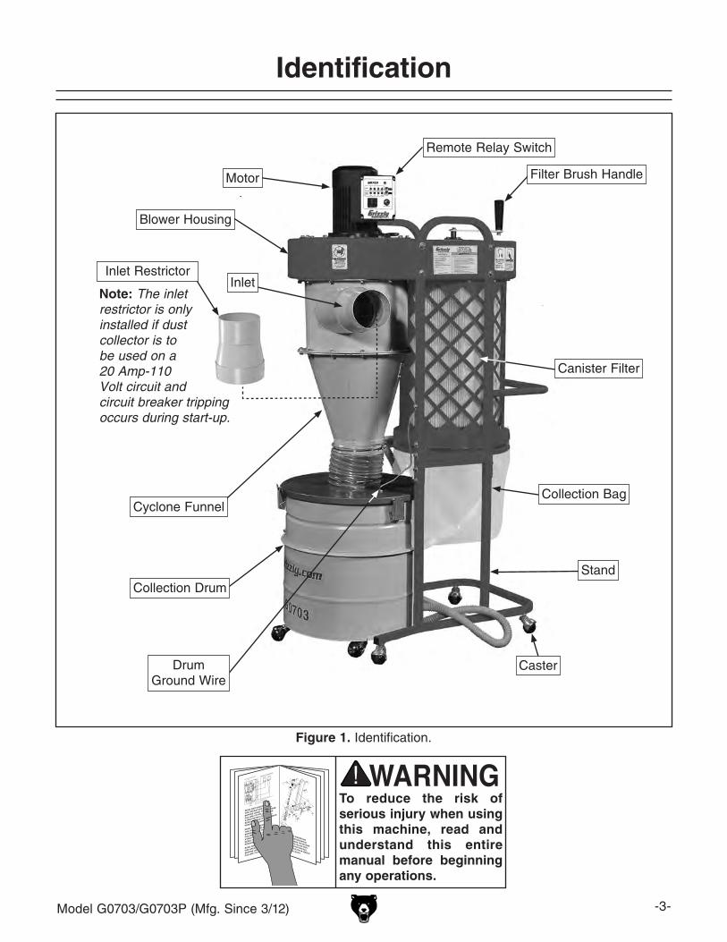
Figure 1. Identification.
Identification
To reduce the risk of serious injury when using this machine, read and understand this entire manual before beginning any operations.
Motor
Blower Housing
Inlet
Canister Filter
Cyclone Funnel
Collection Drum
Collection Bag
Filter Brush Handle
Stand
Caster
Note: The inlet restrictor is only installed if dust collector is to be used on a 20 Amp-110 Volt circuit and circuit breaker tripping occurs during start-up.
Inlet Restrictor
Drum Ground Wire
Remote Relay Switch
-4- Model G0703/G0703P (Mfg. Since 3/12)
The following is a list of common definitions, terms and phrases that relate to dust collection and dust col-lectors in general. To get the most out of this manual, familiarize yourself with these terms before reading.
Air Suction Capacity: The maximum volume of air (rated in CFM) that a dust collector can move, at the inlet, when fully assembled and not connected to any ducting.
Branch Line: A secondary length of duct that connects a dust-producing machine to the Main Line of a permanent dust collection sys-tem. The minimum recommended Velocity for branch lines is 4000 FPM.
Collection Bag/Drum: The part of the dust col-lector that holds the majority of captured dust.
CFM (Cubic Feet per Minute): A measurement describing the volume of air that moves through an area in one minute. CFM = Velocity (FPM) x Cross-Sectional Area of Duct (ft.2).
Cyclone: A type of two-stage dust collector that uses centrifugal force to remove large dust par-ticles before they can reach the filter.
Duct (Ducting): Metal/plastic pipe or hose that connects the dust collector to dust-producing machines. Typically available in rigid or flexible options.
Dust Collection System: The entire assembly of dust collector, duct, and fittings used to capture dust from machines.
Dust Port/Hood: The part of a dust-producing machine that connects to dust collection duct.
Filter: The part of the dust collector that prevents the majority of suctioned dust from returning to the shop environment. Filters are rated by the size of fine dust (measured in microns) that can pass through them.
Fittings (Y's, T's, Elbows, etc.): The various duct connections that allow the branch and main lines of a dust collection system to be routed from the machine to the dust collector.
Duct Grounding: A method of using bare wire with plastic duct to safely dissipate static elec-tricity buildup during operation.
Main Line: The primary length of duct that con-nects the dust collector to the branch lines of a permanent dust collection system. The mini-mum recommended Velocity for main lines is 3500 FPM.
Machine CFM Requirement: Indicates the mini-mum amount of airflow required at the dust port/hood of a dust-producing machine for adequate removal of the waste produced. Essentially, the performance required by the Dust Collection System after accounting for the drop in CFM from the static pressure loss of the duct line between the machine and the dust collector.
Powered Air Filter: An independently operated machine that removes fine dust suspended in the air. Typically operated during and after dust-producing operations as a secondary method to improve the air quality in a shop.
Single-Stage Collector: A type of dust collector where all collected chips and dust are expelled directly into the filter.
Static Pressure: Expressed in units of inches of water, this describes the difference in pressure between the air inside and outside the dust col-lector. It is a measure of the suction created by the blower.
Two-Stage Collector: A type of dust collector where large/heavy waste is captured in a sepa-rate container before the airflow reaches the filter. Benefits include longer operation times between filter maintenance or replacement.
Velocity: The speed of airflow movement, mea-sured in FPM (Feet Per Minute). Velocity = Volume (CFM) / Cross-Sectional Area of Duct (ft.2).
Glossary Of Terms
Model G0703/G0703P (Mfg. Since 3/12) -5-
MODEL G0703PPOLAR BEAR SERIES
1-1/2 HP CYCLONE DUST COLLECTOR
Customer Service #: (570) 546-9663 • To Order Call: (800) 523-4777 • Fax #: (800) 438-5901
MACHINE DATA SHEET
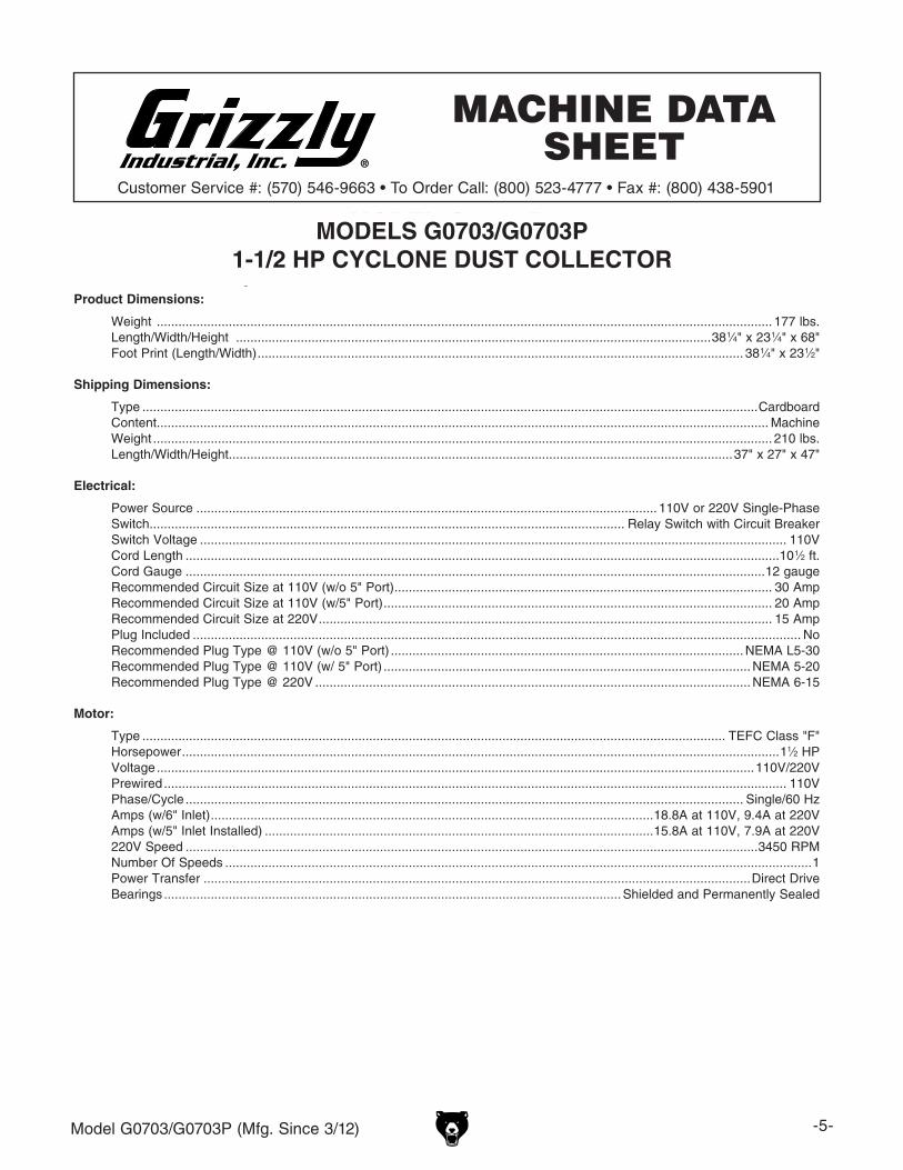
Product Dimensions:
Weight ........................................................................................................................................................................... 177 lbs.Length/Width/Height ....................................................................................................................................38 1⁄4" x 23 1⁄4" x 68"Foot Print (Length/Width) ....................................................................................................................................... 38 1⁄4" x 23 1⁄2"
Shipping Dimensions:
Type ...........................................................................................................................................................................CardboardContent .......................................................................................................................................................................... MachineWeight ............................................................................................................................................................................ 210 lbs.Length/Width/Height ............................................................................................................................................37" x 27" x 47"
Electrical:
Power Source ................................................................................................................................ 110V or 220V Single-PhaseSwitch .................................................................................................................................... Relay Switch with Circuit BreakerSwitch Voltage ................................................................................................................................................................... 110VCord Length .....................................................................................................................................................................10 1⁄2 ft.Cord Gauge .................................................................................................................................................................12 gaugeRecommended Circuit Size at 110V (w/o 5" Port) ......................................................................................................... 30 AmpRecommended Circuit Size at 110V (w/5" Port) ............................................................................................................ 20 AmpRecommended Circuit Size at 220V .............................................................................................................................. 15 AmpPlug Included ......................................................................................................................................................................... NoRecommended Plug Type @ 110V (w/o 5" Port) .................................................................................................. NEMA L5-30Recommended Plug Type @ 110V (w/ 5" Port) ...................................................................................................... NEMA 5-20Recommended Plug Type @ 220V ......................................................................................................................... NEMA 6-15
Motor:
Type .................................................................................................................................................................. TEFC Class "F"Horsepower ......................................................................................................................................................................11⁄2 HPVoltage ......................................................................................................................................................................110V/220VPrewired ............................................................................................................................................................................. 110VPhase/Cycle ........................................................................................................................................................... Single/60 HzAmps (w/6" Inlet) ...........................................................................................................................18.8A at 110V, 9.4A at 220V Amps (w/5" Inlet Installed) ............................................................................................................15.8A at 110V, 7.9A at 220V220V Speed ...............................................................................................................................................................3450 RPMNumber Of Speeds ...................................................................................................................................................................1Power Transfer ........................................................................................................................................................Direct DriveBearings ............................................................................................................................... Shielded and Permanently Sealed
Model G0703P Page 1 of 2
Machine Data Sheet
MODELS G0703/G0703P 1-1/2 HP CYCLONE DUST COLLECTOR
-6- Model G0703/G0703P (Mfg. Since 3/12)
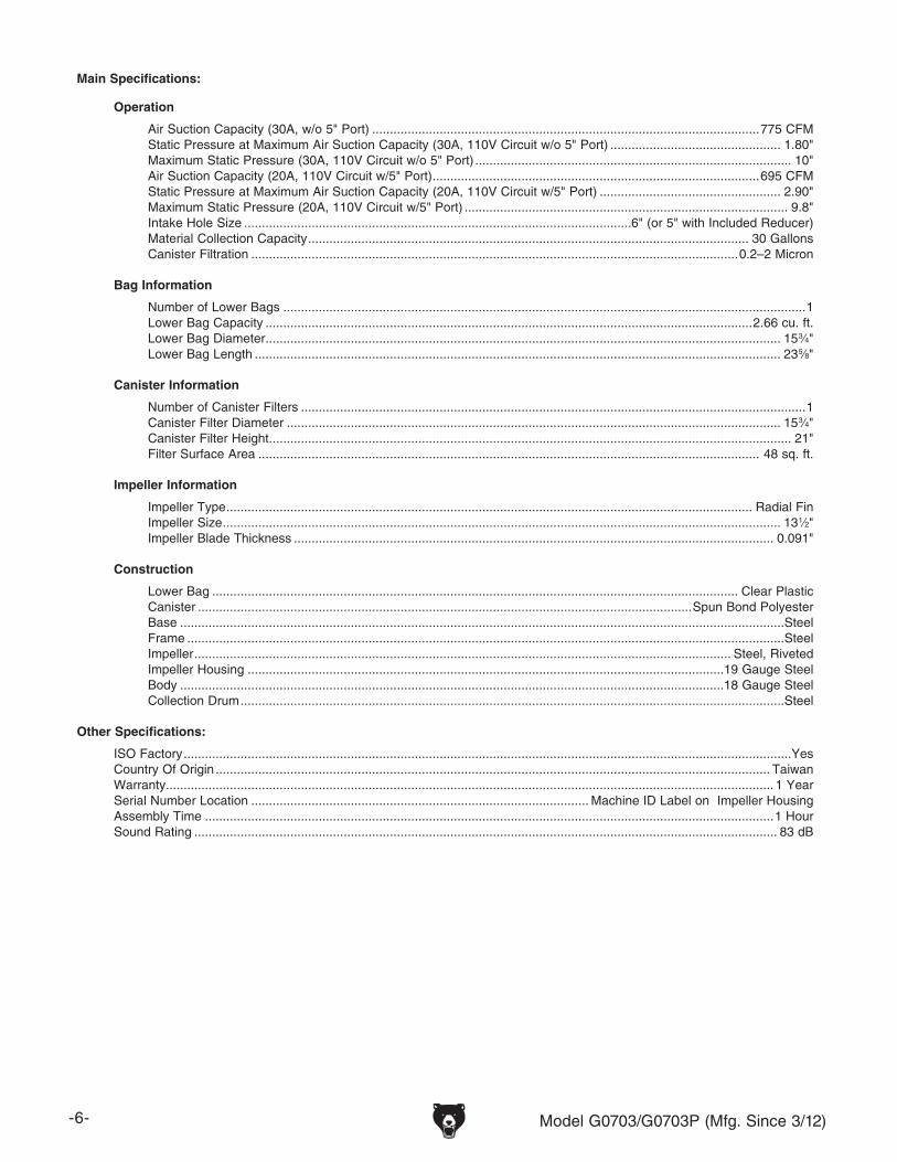
Main Specifications:
Operation
Air Suction Capacity (30A, w/o 5" Port) .............................................................................................................775 CFMStatic Pressure at Maximum Air Suction Capacity (30A, 110V Circuit w/o 5" Port) ................................................ 1.80"Maximum Static Pressure (30A, 110V Circuit w/o 5" Port) ......................................................................................... 10"Air Suction Capacity (20A, 110V Circuit w/5" Port) ............................................................................................695 CFMStatic Pressure at Maximum Air Suction Capacity (20A, 110V Circuit w/5" Port) ................................................... 2.90"Maximum Static Pressure (20A, 110V Circuit w/5" Port) ........................................................................................... 9.8"Intake Hole Size .............................................................................................................6" (or 5" with Included Reducer)Material Collection Capacity ............................................................................................................................ 30 GallonsCanister Filtration .........................................................................................................................................0.2–2 Micron
Bag Information
Number of Lower Bags ...................................................................................................................................................1Lower Bag Capacity .........................................................................................................................................2.66 cu. ft.Lower Bag Diameter ................................................................................................................................................. 15 3⁄4"Lower Bag Length .................................................................................................................................................... 23 5⁄8"
Canister Information
Number of Canister Filters ..............................................................................................................................................1Canister Filter Diameter ........................................................................................................................................... 15 3⁄4"Canister Filter Height ................................................................................................................................................... 21"Filter Surface Area ............................................................................................................................................. 48 sq. ft.
Impeller Information
Impeller Type .................................................................................................................................................... Radial FinImpeller Size ............................................................................................................................................................. 13 1⁄2"Impeller Blade Thickness ....................................................................................................................................... 0.091"
Construction
Lower Bag .................................................................................................................................................... Clear PlasticCanister ...........................................................................................................................................Spun Bond PolyesterBase ..........................................................................................................................................................................SteelFrame ........................................................................................................................................................................SteelImpeller ....................................................................................................................................................... Steel, RivetedImpeller Housing ......................................................................................................................................19 Gauge SteelBody .........................................................................................................................................................18 Gauge SteelCollection Drum .........................................................................................................................................................Steel
Other Specifications:
ISO Factory ...........................................................................................................................................................................YesCountry Of Origin ............................................................................................................................................................ TaiwanWarranty ........................................................................................................................................................................... 1 YearSerial Number Location ............................................................................................... Machine ID Label on Impeller HousingAssembly Time ................................................................................................................................................................1 HourSound Rating .................................................................................................................................................................... 83 dB
Features:
White, powder-coated finishSteel collection drum with casters for easy dust disposalPowerful Class "F" motor for continuous dutyDual pleated filter with cleaning brushes to maximize air flow and steel cage for protection256-code remote control receiverIR hand-held controller can turn dust collector on up to 75 feet away
Model G0703P Page 2 of 2

Model G0703/G0703P (Mfg. Since 3/12) -7-
ELECTRICAL EQUIPMENT INJURY RISKS. You can be shocked, burned, or killed by touching live electrical components or improperly grounded machinery. To reduce this risk, only allow qualified service personnel to do electrical installation or repair work, and always disconnect power before accessing or exposing electrical equipment.
DISCONNECT POWER FIRST. Always discon-nect machine from power supply BEFORE making adjustments, changing tooling, or servicing machine. This prevents an injury risk from unintended startup or contact with live electrical components.
EYE PROTECTION. Always wear ANSI-approved safety glasses or a face shield when operating or observing machinery to reduce the risk of eye injury or blindness from flying particles. Everyday eyeglasses are NOT approved safety glasses.
OWNER’S MANUAL. Read and understand this owner’s manual BEFORE using machine.
TRAINED OPERATORS ONLY. Untrained oper-ators have a higher risk of being hurt or killed. Only allow trained/supervised people to use this machine. When machine is not being used, dis-connect power, remove switch keys, or lock-out machine to prevent unauthorized use—especially around children. Make workshop kid proof!
DANGEROUS ENVIRONMENTS. Do not use machinery in areas that are wet, cluttered, or have poor lighting. Operating machinery in these areas greatly increases the risk of accidents and injury.
MENTAL ALERTNESS REQUIRED. Full mental alertness is required for safe operation of machin-ery. Never operate under the influence of drugs or alcohol, when tired, or when distracted.
For Your Own Safety, Read Instruction Manual Before Operating This Machine
The purpose of safety symbols is to attract your attention to possible hazardous conditions. This manual uses a series of symbols and signal words intended to convey the level of impor-tance of the safety messages. The progression of symbols is described below. Remember that safety messages by themselves do not eliminate danger and are not a substitute for proper accident prevention measures. Always use common sense and good judgment.
Indicates a potentially hazardous situation which, if not avoided, MAY result in minor or moderate injury. It may also be used to alert against unsafe practices.
Indicates a potentially hazardous situation which, if not avoided, COULD result in death or serious injury.
Indicates an imminently hazardous situation which, if not avoided, WILL result in death or serious injury.
This symbol is used to alert the user to useful information about proper operation of the machine.NOTICE
Safety Instructions for Machinery
SECTION 1: SAFETY
-8- Model G0703/G0703P (Mfg. Since 3/12)
WEARING PROPER APPAREL. Do not wear clothing, apparel or jewelry that can become entangled in moving parts. Always tie back or cover long hair. Wear non-slip footwear to reduce risk of slipping and losing control or accidentally contacting cutting tool or moving parts.
HAZARDOUS DUST. Dust created by machinery operations may cause cancer, birth defects, or long-term respiratory damage. Be aware of dust hazards associated with each workpiece mate-rial. Always wear a NIOSH-approved respirator to reduce your risk.
HEARING PROTECTION. Always wear hear-ing protection when operating or observing loud machinery. Extended exposure to this noise without hearing protection can cause permanent hearing loss.
REMOVE ADJUSTING TOOLS. Tools left on machinery can become dangerous projectiles upon startup. Never leave chuck keys, wrenches, or any other tools on machine. Always verify removal before starting!
USE CORRECT TOOL FOR THE JOB. Only use this tool for its intended purpose—do not force it or an attachment to do a job for which it was not designed. Never make unapproved modifica-tions—modifying tool or using it differently than intended may result in malfunction or mechanical failure that can lead to personal injury or death!
AWKWARD POSITIONS. Keep proper footing and balance at all times when operating machine. Do not overreach! Avoid awkward hand positions that make workpiece control difficult or increase the risk of accidental injury.
CHILDREN & BYSTANDERS. Keep children and bystanders at a safe distance from the work area.Stop using machine if they become a distraction.
GUARDS & COVERS. Guards and covers reduce accidental contact with moving parts or flying debris. Make sure they are properly installed, undamaged, and working correctly BEFORE operating machine.
FORCING MACHINERY. Do not force machine. It will do the job safer and better at the rate for which it was designed.
NEVER STAND ON MACHINE. Serious injury may occur if machine is tipped or if the cutting tool is unintentionally contacted.
STABLE MACHINE. Unexpected movement dur-ing operation greatly increases risk of injury or loss of control. Before starting, verify machine is stable and mobile base (if used) is locked.
USE RECOMMENDED ACCESSORIES. Consult this owner’s manual or the manufacturer for rec-ommended accessories. Using improper acces-sories will increase the risk of serious injury.
UNATTENDED OPERATION. To reduce the risk of accidental injury, turn machine OFF and ensure all moving parts completely stop before walking away. Never leave machine running while unattended.
MAINTAIN WITH CARE. Follow all maintenance instructions and lubrication schedules to keep machine in good working condition. A machine that is improperly maintained could malfunction, leading to serious personal injury or death.
DAMAGED PARTS. Regularly inspect machine for damaged, loose, or mis-adjusted parts—or any condition that could affect safe operation. Immediately repair/replace BEFORE operating machine. For your own safety, DO NOT operate machine with damaged parts!
MAINTAIN POWER CORDS. When disconnect-ing cord-connected machines from power, grab and pull the plug—NOT the cord. Pulling the cord may damage the wires inside. Do not handle cord/plug with wet hands. Avoid cord damage by keeping it away from heated surfaces, high traffic areas, harsh chemicals, and wet/damp locations.
EXPERIENCING DIFFICULTIES. If at any time you experience difficulties performing the intend-ed operation, stop using the machine! Contact our Technical Support at (570) 546-9663.

Model G0703/G0703P (Mfg. Since 3/12) -9-
INTENDED USE. This dust collector is only intended for collecting wood dust and chips from woodworking machines. DO NOT use this dust collector to collect metal, dirt, pebbles, drywall, asbestos, lead paint, silica, liquids, aerosols, or any flammable, combustible, or hazardous materi-als.
HAZARDOUS DUST. Dust created while using machinery may cause cancer, birth defects, or long-term respiratory damage. Be aware of dust hazards associated with each workpiece material, and always wear a NIOSH-approved respirator to reduce your risk.
DUST ALLERGIES. Dust from certain woods may cause an allergic reaction in people and ani-mals. Make sure you know what type of wood dust you will be exposed to in case there is a possibility of an allergic reaction.
WEAR RESPIRATOR. Fine dust that is too small to be caught in the filter will be blown into the ambient air during operation. Always wear a NIOSH approved respirator during operation and for a short time after to reduce your risk of perma-nent respiratory damage.
EMPTYING DUST. When emptying dust from the collection container, wear a respirator and safety glasses. Empty dust away from ignition sources and into an approved container.
DISCONNECTING POWER SUPPLY. Turn the switch OFF, disconnect the dust collector from the power supply, and allow the impeller to come to a complete stop before leaving the machine unattended or doing any service, cleaning, main-tenance, or adjustments.
REGULAR CLEANING. Regularly check/empty the collection bags or drum to avoid the buildup of fine dust that can increase the risk of fire. Make sure to regularly clean the surrounding area where the machine is operated—excessive dust buildup on overhead lights, heaters, electrical panels, or other heat sources will increase the risk of fire.
SUSPENDED DUST PARTICLES AND IGNITION SOURCES. DO NOT operate the dust collector in areas were explosion risks are high. Areas of high risk include, but are not limited to, areas near pilot lights, open flames, or other ignition sources.
FIRE SUPPRESSION. Only operate the dust col-lector in locations that contain a fire suppression system or have a fire extinguisher nearby.
IMPELLER HAZARDS. DO NOT place your hands or tools near the open inlet during operation for any reason. The powerful suction could easily cause accidental contact with the impeller which will cause serious personal injury or damage to the machine. Always keep small animals and chil-dren away from open dust collection inlets.
AVOIDING SPARKS. DO NOT allow steel or rocks to strike the impeller—this may produce sparks. Sparks can smolder in wood dust for a long time before a fire is detected. If you acciden-tally cut into wood containing tramp metal (nails, staples, spikes, etc.), immediately turn OFF the dust collector, disconnect it from power, and wait for the impeller to stop—then empty the collec-tion container into an approved airtight metal container.
OPERATING LOCATION. To reduce respira-tory exposure to fine dust, locate permanently installed dust collectors away from the working area, or in another room that is equipped with a smoke detector. DO NOT operate the dust collec-tor in rainy or wet locations—exposure to water may create an shock hazard or decrease the life of the machine.
STATIC ELECTRICITY. Plastic dust lines gener-ate high amounts of static electricity as dust chips pass through them. Although rare, sparks caused by static electricity can cause explosions or fire. To reduce this risk, make sure all dust lines are thoroughly grounded by using a grounding wire.
Additional Safety for Dust Collectors

-10- Model G0703/G0703P (Mfg. Since 3/12)
SECTION 2: POWER SUPPLY
AvailabilityBefore installing the machine, consider the avail-ability and proximity of the required power supply circuit. If an existing circuit does not meet the requirements for this machine, a new circuit must be installed. To minimize the risk of electrocution, fire, or equipment damage, installation work and electrical wiring must be done by an electrician or qualified service personnel in accordance with all applicable codes and standards.
Electrocution, fire, or equipment damage may occur if machine is not correctly grounded and connected to the power supply.
Full-Load Current RatingThe full-load current rating is the amperage a machine draws at 100% of the rated output power. On machines with multiple motors, this is the amperage drawn by the largest motor or sum of all motors and electrical devices that might operate at one time during normal operations.
Full-Load Current Rating at 110VWith Inlet Restrictor Installed ........ 15.8 AmpsWithout Inlet Restrictor Installed ... 18.8 Amps
Full-Load Current Rating at 220VWith Inlet Restrictor Installed .......... 7.9 AmpsWithout Inlet Restrictor Installed ..... 9.4 Amps
The full-load current is not the maximum amount of amps that the machine will draw. If the machine is overloaded, it will draw additional amps beyond the full-load rating.
If the machine is overloaded for a sufficient length of time, damage, overheating, or fire may result—especially if connected to an undersized circuit. To reduce the risk of these hazards, avoid over-loading the machine during operation and make sure it is connected to a power supply circuit that meets the specified circuit requirements.
Circuit InformationA power supply circuit includes all electrical equipment between the breaker box or fuse panel in the building and the machine. The power sup-ply circuit used for this machine must be sized to safely handle the full-load current drawn from the machine for an extended period of time. (If this machine is connected to a circuit protected by fuses, use a time delay fuse marked D.)
For your own safety and protection of property, consult an electrician if you are unsure about wiring practices or electrical codes in your area.
Note: Circuit requirements in this manual apply to a dedicated circuit—where only one machine will be running on the circuit at a time. If machine will be connected to a shared circuit where multiple machines may be running at the same time, con-sult an electrician or qualified service personnel to ensure circuit is properly sized for safe operation.
This machine is prewired to operate on a power supply circuit that has a verified ground and meets the following requirements:
Circuit Requirements for 110V
Nominal Voltage ...............................110V/120VCycle ..........................................................60 HzPhase ........................................... Single-Phase
* An inlet restrictor is included to reduce the amperage draw below 16A, so the machine can be used on common 20A power supply circuits—without exceeding the ampacity of the circuit at 125% of the full-load current rating. Although the machine can operate on a 20A circuit without installing the restrictor, we do not recommend it.
Without Inlet Restrictor*Circuit Rating ...................................... 30 AmpsPlug/Receptacle ...........................NEMA L5-30
With Inlet Restrictor*Circuit Rating ...................................... 20 AmpsPlug/Receptacle ............................. NEMA 5-20
Model G0703/G0703P (Mfg. Since 3/12) -11-
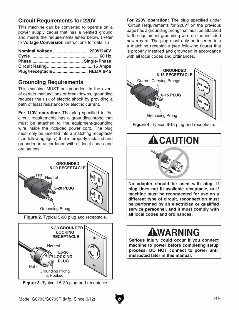
No adapter should be used with plug. If plug does not fit available receptacle, or if machine must be reconnected for use on a different type of circuit, reconnection must be performed by an electrician or qualified service personnel, and it must comply with all local codes and ordinances.
Figure 4. Typical 6-15 plug and receptacle.
Grounding Prong
Current Carrying Prongs
6-15 PLUG
GROUNDED6-15 RECEPTACLE
Serious injury could occur if you connect machine to power before completing setup process. DO NOT connect to power until instructed later in this manual.
Figure 3. Typical L5-30 plug and receptacle.
Grounding Prongis Hooked
Hot
Neutral
L5-30 GROUNDEDLOCKING
RECEPTACLE
L5-30LOCKING
PLUG
Figure 2. Typical 5-20 plug and receptacle.
Grounding Prong
HotNeutral
5-20 PLUG
GROUNDED5-20 RECEPTACLE
Grounding RequirementsThis machine MUST be grounded. In the event of certain malfunctions or breakdowns, grounding reduces the risk of electric shock by providing a path of least resistance for electric current.
For 110V operation: The plug specified in the circuit requirements has a grounding prong that must be attached to the equipment-grounding wire inside the included power cord. The plug must only be inserted into a matching receptacle (see following figure) that is properly installed and grounded in accordance with all local codes and ordinances.
For 220V operation: The plug specified under “Circuit Requirements for 220V” on the previous page has a grounding prong that must be attached to the equipment-grounding wire on the included power cord. The plug must only be inserted into a matching receptacle (see following figure) that is properly installed and grounded in accordance with all local codes and ordinances.
Circuit Requirements for 220V
Nominal Voltage .............................. 220V/240VCycle ..........................................................60 HzPhase ........................................... Single-PhaseCircuit Rating ...................................... 15 AmpsPlug/Receptacle ............................. NEMA 6-15
This machine can be converted to operate on a power supply circuit that has a verified ground and meets the requirements listed below. (Refer to Voltage Conversion instructions for details.)
-12- Model G0703/G0703P (Mfg. Since 3/12)
Improper connection of the equipment-grounding wire can result in a risk of electric shock. The wire with green insulation (with or without yellow stripes) is the equipment-grounding wire. If repair or replacement of the power cord or plug is nec-essary, do not connect the equipment-grounding wire to a live (current carrying) terminal. Check with a qualified electrician or service per-sonnel if you do not understand these grounding requirements, or if you are in doubt about whether the tool is properly grounded. If you ever notice that a cord or plug is damaged or worn, discon-nect it from power, and immediately replace it with a new one.
Extension CordsWe do not recommend using an extension cord with this machine. If you must use an extension cord, only use it if absolutely necessary and only on a temporary basis.
Extension cords cause voltage drop, which can damage electrical components and shorten motor life. Voltage drop increases as the extension cord size gets longer and the gauge size gets smaller (higher gauge numbers indicate smaller sizes).
Any extension cord used with this machine must be in good condition and contain a ground wire and matching plug/receptacle. Additionally, it must meet the following size requirements:
Minimum Gauge Size ...........................12 AWGMaximum Length (Shorter is Better).......50 ft.
Voltage Conversion
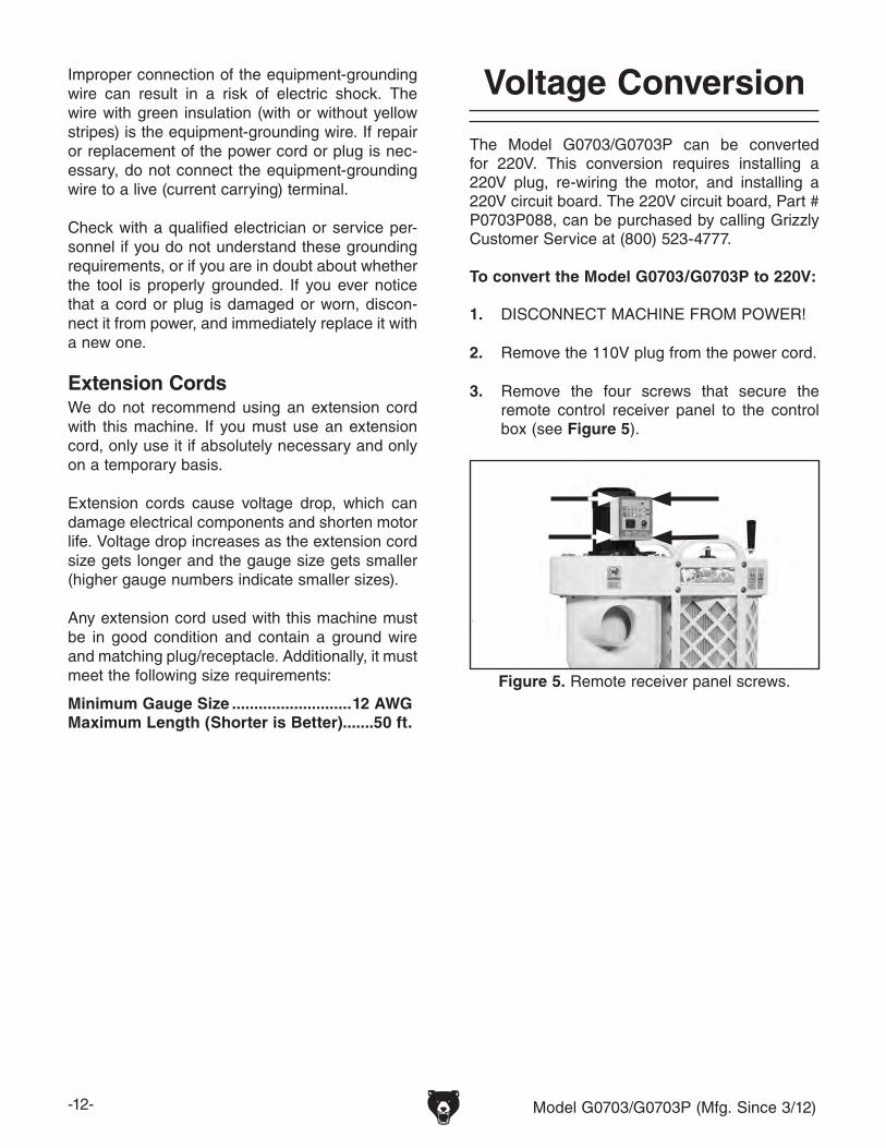
The Model G0703/G0703P can be converted for 220V. This conversion requires installing a 220V plug, re-wiring the motor, and installing a 220V circuit board. The 220V circuit board, Part # P0703P088, can be purchased by calling Grizzly Customer Service at (800) 523-4777.
To convert the Model G0703/G0703P to 220V:
1. DISCONNECT MACHINE FROM POWER!
2. Remove the 110V plug from the power cord.
Figure 5. Remote receiver panel screws.
3. Remove the four screws that secure the remote control receiver panel to the control box (see Figure 5).
Model G0703/G0703P (Mfg. Since 3/12) -13-
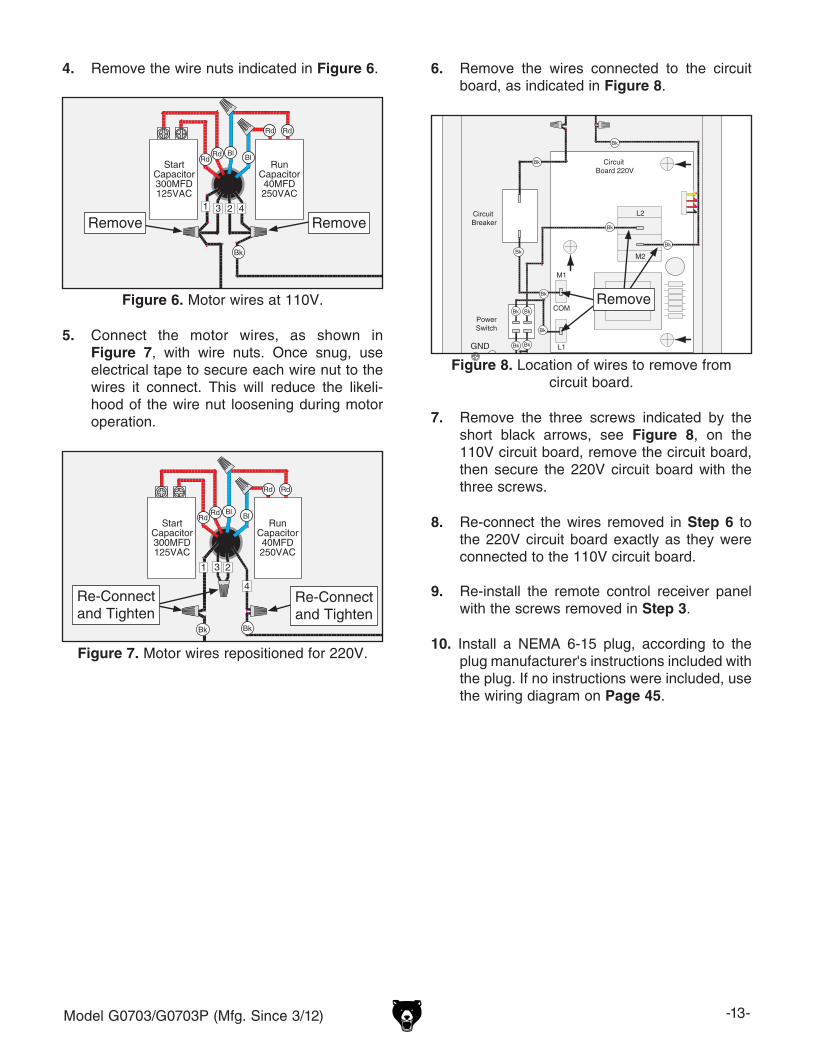
4. Remove the wire nuts indicated in Figure 6.
MOTOR 110V
Hot
Neutral
Ground
1 23 4
RunCapacitor40MFD250VAC
GND
StartCapacitor300MFD125VAC
G
W
Power Switch
Circuit Breaker
Circuit Board 110V
L2
L1
COM
M2
M1
110 VAC(Prewired)
L5-30 Plug(As Recommended)
Figure 6. Motor wires at 110V.
Remove Remove
5. Connect the motor wires, as shown in Figure 7, with wire nuts. Once snug, use electrical tape to secure each wire nut to the wires it connect. This will reduce the likeli-hood of the wire nut loosening during motor operation.
2
RunCapacitor40MFD250VAC
GND
StartCapacitor300MFD125VAC
PowerSwitch
Thermal Overload
Circuit Board 220V
L2
L1
COM
M2
M1
4
31
MOTOR 220V
Hot
Hot
Ground
6-15 Plug(Rewired 220V)
220VAC
G
Figure 7. Motor wires repositioned for 220V.
Re-Connect and Tighten
Re-Connect and Tighten
6. Remove the wires connected to the circuit board, as indicated in Figure 8.
Figure 8. Location of wires to remove from circuit board.
2
RunCapacitor40MFD250VAC
GND
StartCapacitor300MFD125VAC
PowerSwitch
Circuit Breaker
Circuit Board 220V
L2
L1
COM
M2
M1
3
41
MOTOR 220V
Hot
Hot
Ground
220VAC
G
Remove
7. Remove the three screws indicated by the short black arrows, see Figure 8, on the 110V circuit board, remove the circuit board, then secure the 220V circuit board with the three screws.
8. Re-connect the wires removed in Step 6 to the 220V circuit board exactly as they were connected to the 110V circuit board.
9. Re-install the remote control receiver panel with the screws removed in Step 3.
10. Install a NEMA 6-15 plug, according to the plug manufacturer's instructions included with the plug. If no instructions were included, use the wiring diagram on Page 45.
-14- Model G0703/G0703P (Mfg. Since 3/12)
SECTION 3: SETUP
This machine presents serious injury hazards to untrained users. Read through this entire manu-al to become familiar with the controls and opera-tions before starting the machine!
This machine and its com-ponents are very heavy. Get lifting help or use power lifting equipment such as a forklift to move heavy items.
This machine was carefully packaged for safe transport. When unpacking, separate all enclosed items from packaging materials and inspect them for shipping damage. If items are damaged, please call us immediately at (570) 546-9663.
IMPORTANT: Save all packaging materials until you are completely satisfied with the machine and have resolved any issues between Grizzly or the shipping agent. You MUST have the original pack-aging to file a freight claim. It is also extremely helpful if you need to return your machine later.
Unpacking
SUFFOCATION HAZARD!Keep children and pets away from plastic bags or packing materials shipped with this machine. Discard immediately.
Needed for Setup
The following items are needed to complete the setup process, but are not included with your machine:
Description Qty• Assistant ..................................................... 1• Safety Glasses .................. For Each Person• Wrench 3⁄8" ................................................. 2• Wrench 5⁄16" ................................................ 1• Phillips Head Screwdriver #2 ..................... 1
Model G0703/G0703P (Mfg. Since 3/12) -15-
5mm
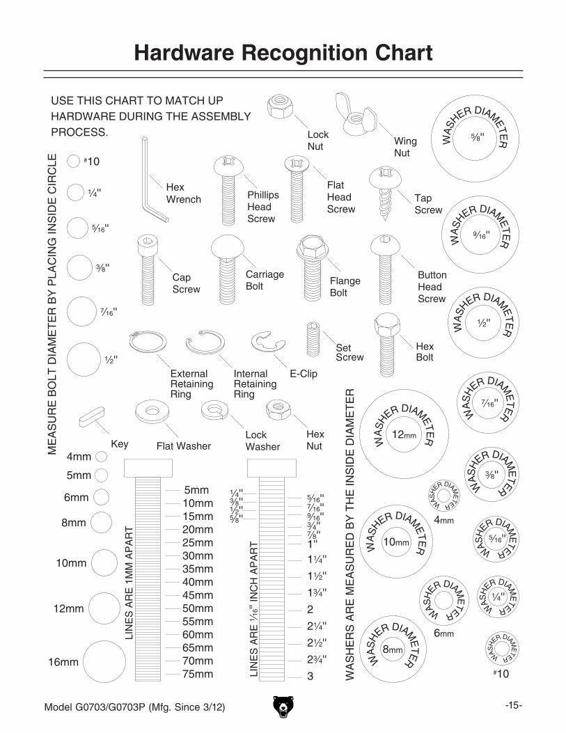
Hardware Recognition Chart
-16- Model G0703/G0703P (Mfg. Since 3/12)
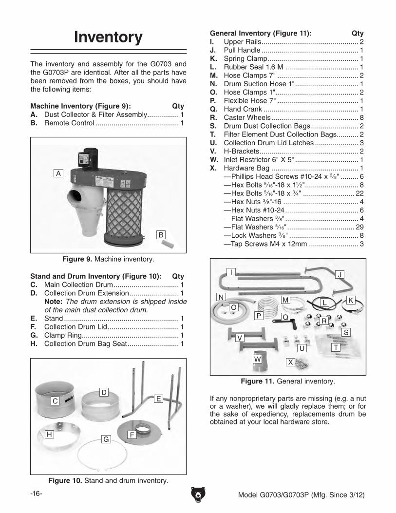
Inventory
The inventory and assembly for the G0703 and the G0703P are identical. After all the parts have been removed from the boxes, you should have the following items:
Machine Inventory (Figure 9): QtyA. Dust Collector & Filter Assembly ................ 1B. Remote Control .......................................... 1
General Inventory (Figure 11): QtyI. Upper Rails ................................................. 2J. Pull Handle ................................................. 1K. Spring Clamp .............................................. 1L. Rubber Seal 1.6 M ..................................... 1M. Hose Clamps 7" ......................................... 2N. Drum Suction Hose 1" ................................ 1O. Hose Clamps 1" .......................................... 2P. Flexible Hose 7" ......................................... 1Q. Hand Crank ................................................ 1R. Caster Wheels ............................................ 8S. Drum Dust Collection Bags ........................ 2T. Filter Element Dust Collection Bags ........... 2U. Collection Drum Lid Latches ...................... 3V. H-Brackets .................................................. 2W. Inlet Restrictor 6" X 5" ................................ 1X. Hardware Bag ............................................ 1
—Phillips Head Screws #10-24 x 3⁄8" ......... 6—Hex Bolts 5⁄16"-18 x 11⁄2" ........................... 8—Hex Bolts 5⁄16"-18 x 3⁄4" .......................... 22—Hex Nuts 3⁄8"-16 ...................................... 4—Hex Nuts #10-24 ..................................... 6—Flat Washers 3⁄8" ..................................... 4—Flat Washers 5⁄16" .................................. 29—Lock Washers 3⁄8" ................................... 8—Tap Screws M4 x 12mm ......................... 3
Stand and Drum Inventory (Figure 10): QtyC. Main Collection Drum ................................. 1D. Collection Drum Extension ......................... 1 Note: The drum extension is shipped inside
of the main dust collection drum.E. Stand .......................................................... 1F. Collection Drum Lid .................................... 1G. Clamp Ring ................................................. 1H. Collection Drum Bag Seat .......................... 1
Figure 10. Stand and drum inventory.
CD
E
H FG
If any nonproprietary parts are missing (e.g. a nut or a washer), we will gladly replace them; or for the sake of expediency, replacements drum be obtained at your local hardware store.
Figure 11. General inventory.
I J
NO
P
M L K
W
V
Q
U T
R
S
X
Figure 9. Machine inventory.
A
B
Model G0703/G0703P (Mfg. Since 3/12) -17-
Site Considerations
Weight LoadRefer to the Machine Data Sheet for the weight of your machine. Make sure that the surface upon which the machine is placed will bear the weight of the machine, additional equipment that may be installed on the machine, and the heaviest work-piece that will be used. Additionally, consider the weight of the operator and any dynamic loading that may occur when operating the machine.
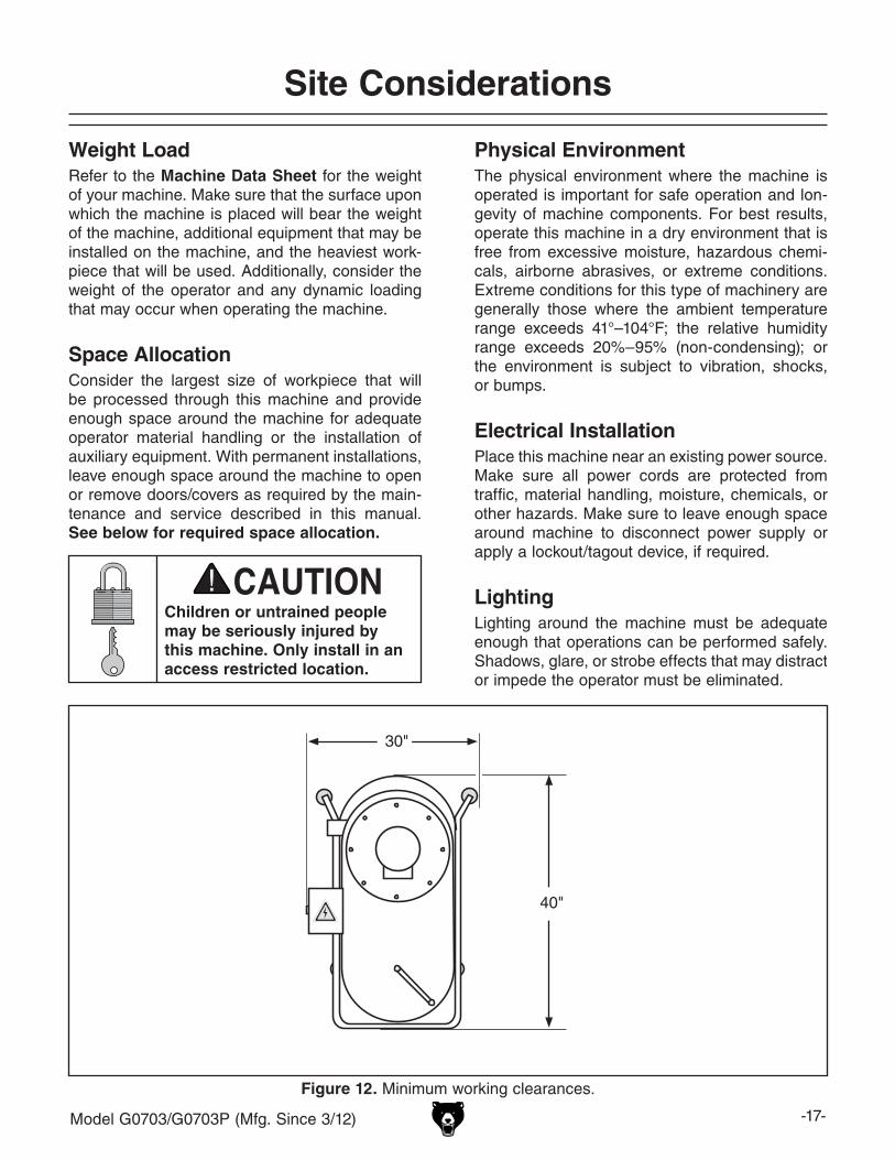
Space AllocationConsider the largest size of workpiece that will be processed through this machine and provide enough space around the machine for adequate operator material handling or the installation of auxiliary equipment. With permanent installations, leave enough space around the machine to open or remove doors/covers as required by the main-tenance and service described in this manual. See below for required space allocation.
Physical EnvironmentThe physical environment where the machine is operated is important for safe operation and lon-gevity of machine components. For best results, operate this machine in a dry environment that is free from excessive moisture, hazardous chemi-cals, airborne abrasives, or extreme conditions. Extreme conditions for this type of machinery are generally those where the ambient temperature range exceeds 41°–104°F; the relative humidity range exceeds 20%–95% (non-condensing); or the environment is subject to vibration, shocks, or bumps.
Electrical InstallationPlace this machine near an existing power source. Make sure all power cords are protected from traffic, material handling, moisture, chemicals, or other hazards. Make sure to leave enough space around machine to disconnect power supply or apply a lockout/tagout device, if required.
LightingLighting around the machine must be adequate enough that operations can be performed safely. Shadows, glare, or strobe effects that may distract or impede the operator must be eliminated.
Children or untrained people may be seriously injured by this machine. Only install in an access restricted location.
Figure 12. Minimum working clearances.
30"
40"
-18- Model G0703/G0703P (Mfg. Since 3/12)
Assembly
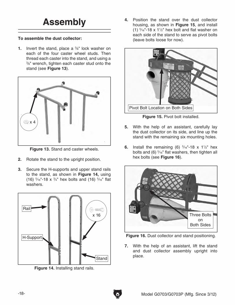
To assemble the dust collector:
1. Invert the stand, place a 3⁄8" lock washer on each of the four caster wheel studs. Then thread each caster into the stand, and using a 3⁄8" wrench, tighten each caster stud onto the stand (see Figure 13).
Figure 13. Stand and caster wheels.
2. Rotate the stand to the upright position.
3. Secure the H-supports and upper stand rails to the stand, as shown in Figure 14, using (16) 5⁄16"-18 x 3⁄4" hex bolts and (16) 5⁄16" flat washers.
Figure 14. Installing stand rails.
H-Support
4. Position the stand over the dust collector housing, as shown in Figure 15, and install (1) 5⁄16"-18 x 11⁄2" hex bolt and flat washer on each side of the stand to serve as pivot bolts (leave bolts loose for now).
Figure 15. Pivot bolt installed.
Pivot Bolt Location on Both Sides
5. With the help of an assistant, carefully lay the dust collector on its side, and line up the stand with the remaining six mounting holes.
7. With the help of an assistant, lift the stand and dust collector assembly upright into place.
6. Install the remaining (6) 5⁄16"-18 x 11⁄2" hex bolts and (6) 5⁄16" flat washers, then tighten all hex bolts (see Figure 16).
Figure 16. Dust collector and stand positioning.
Three Bolts on
Both Sides
x 4
x 16
Rail
Stand
Model G0703/G0703P (Mfg. Since 3/12) -19-
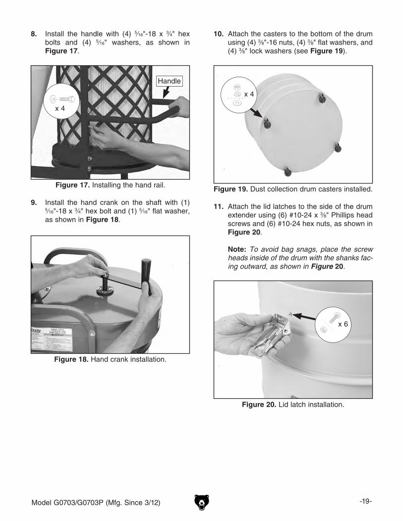
8. Install the handle with (4) 5⁄16"-18 x 3⁄4" hex bolts and (4) 5⁄16" washers, as shown in Figure 17.
Figure 18. Hand crank installation.
9. Install the hand crank on the shaft with (1) 5⁄16"-18 x 3⁄4" hex bolt and (1) 5⁄16" flat washer, as shown in Figure 18.
10. Attach the casters to the bottom of the drum using (4) 3⁄8"-16 nuts, (4) 3⁄8" flat washers, and (4) 3⁄8" lock washers (see Figure 19).
Figure 19. Dust collection drum casters installed.
11. Attach the lid latches to the side of the drum extender using (6) #10-24 x 3⁄8" Phillips head screws and (6) #10-24 hex nuts, as shown in Figure 20.
Note: To avoid bag snags, place the screw heads inside of the drum with the shanks fac-ing outward, as shown in Figure 20.
Figure 17. Installing the hand rail.
Handle
x 4
x 4
Figure 20. Lid latch installation.
x 6
-20- Model G0703/G0703P (Mfg. Since 3/12)
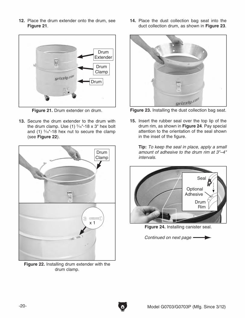
12. Place the drum extender onto the drum, see Figure 21.
Figure 23. Installing the dust collection bag seat.
14. Place the dust collection bag seat into the duct collection drum, as shown in Figure 23.
15. Insert the rubber seal over the top lip of the drum rim, as shown in Figure 24. Pay special attention to the orientation of the seal shown in the inset of the figure.
Tip: To keep the seal in place, apply a small amount of adhesive to the drum rim at 3"–4" intervals.
Figure 24. Installing canister seal.
Seal
DrumRim
Optional Adhesive
13. Secure the drum extender to the drum with the drum clamp. Use (1) 5⁄16"-18 x 3" hex bolt and (1) 5⁄16"-18 hex nut to secure the clamp (see Figure 22).
Figure 22. Installing drum extender with the drum clamp.
DrumClamp
x 1
Figure 21. Drum extender on drum.
DrumExtender
Drum
Drum Clamp
Model G0703/G0703P (Mfg. Since 3/12) -21-
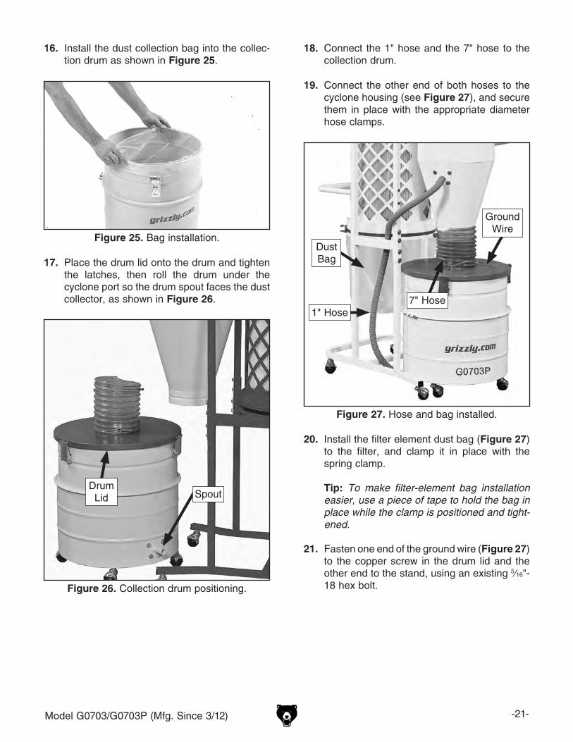
17. Place the drum lid onto the drum and tighten the latches, then roll the drum under the cyclone port so the drum spout faces the dust collector, as shown in Figure 26.
Figure 25. Bag installation.
16. Install the dust collection bag into the collec-tion drum as shown in Figure 25.
19. Connect the other end of both hoses to the cyclone housing (see Figure 27), and secure them in place with the appropriate diameter hose clamps.
18. Connect the 1" hose and the 7" hose to the collection drum.
Figure 26. Collection drum positioning.
Drum Lid Spout
20. Install the filter element dust bag (Figure 27) to the filter, and clamp it in place with the spring clamp.
Tip: To make filter-element bag installation easier, use a piece of tape to hold the bag in place while the clamp is positioned and tight-ened.
21. Fasten one end of the ground wire (Figure 27) to the copper screw in the drum lid and the other end to the stand, using an existing 5⁄16"-18 hex bolt.
Figure 27. Hose and bag installed.
Ground Wire
1" Hose7" Hose
Dust Bag
-22- Model G0703/G0703P (Mfg. Since 3/12)
NOTICEThe Model G0703/G0703P is prewired for 110V. If you plan to operate the machine at 220V, the motor must be rewired (see Page 12) and a 220V switch must be installed.
Power Connection
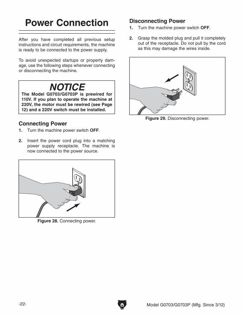
After you have completed all previous setup instructions and circuit requirements, the machine is ready to be connected to the power supply.
To avoid unexpected startups or property dam-age, use the following steps whenever connecting or disconnecting the machine.
Connecting Power
Figure 28. Connecting power.
1. Turn the machine power switch OFF.
2. Insert the power cord plug into a matching power supply receptacle. The machine is now connected to the power source.
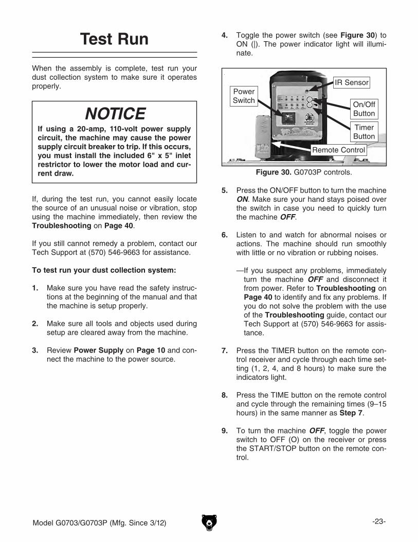
Disconnecting Power
Figure 29. Disconnecting power.
1. Turn the machine power switch OFF.
2. Grasp the molded plug and pull it completely out of the receptacle. Do not pull by the cord as this may damage the wires inside.
Model G0703/G0703P (Mfg. Since 3/12) -23-
Test Run
When the assembly is complete, test run your dust collection system to make sure it operates properly.
If, during the test run, you cannot easily locate the source of an unusual noise or vibration, stop using the machine immediately, then review the Troubleshooting on Page 40.
If you still cannot remedy a problem, contact our Tech Support at (570) 546-9663 for assistance.
To test run your dust collection system:
1. Make sure you have read the safety instruc-tions at the beginning of the manual and that the machine is setup properly.
2. Make sure all tools and objects used during setup are cleared away from the machine.
3. Review Power Supply on Page 10 and con-nect the machine to the power source.
If using a 20-amp, 110-volt power supply circuit, the machine may cause the power supply circuit breaker to trip. If this occurs, you must install the included 6" x 5" inlet restrictor to lower the motor load and cur-rent draw.
NOTICE
4. Toggle the power switch (see Figure 30) to ON (|). The power indicator light will illumi-nate.
5. Press the ON/OFF button to turn the machine ON. Make sure your hand stays poised over the switch in case you need to quickly turn the machine OFF.
6. Listen to and watch for abnormal noises or actions. The machine should run smoothly with little or no vibration or rubbing noises.
— If you suspect any problems, immediately turn the machine OFF and disconnect it from power. Refer to Troubleshooting on Page 40 to identify and fix any problems. If you do not solve the problem with the use of the Troubleshooting guide, contact our Tech Support at (570) 546-9663 for assis-tance.
7. Press the TIMER button on the remote con-trol receiver and cycle through each time set-ting (1, 2, 4, and 8 hours) to make sure the indicators light.
8. Press the TIME button on the remote control and cycle through the remaining times (9–15 hours) in the same manner as Step 7.
9. To turn the machine OFF, toggle the power switch to OFF (O) on the receiver or press the START/STOP button on the remote con-trol.
Figure 30. G0703P controls.
Power Switch On/Off
Button
TimerButton
Remote Control
IR Sensor
-24- Model G0703/G0703P (Mfg. Since 3/12)
SECTION 4: DESIGNING THE SYSTEM
Duct MaterialGeneral
You have many choices regarding main line and branch line duct material. For best results, use metal duct for the main line and branch lines, then use short lengths of flexible hose to connect each machine to the branch lines.
Plastic duct is also a popular material for home shops. However, be aware that there is a fire or explosion hazard if plastic duct material is used for dust collection without being grounded against static electrical charge build-up. This topic will be discussed later in this section. Another problem with using plastic is that it is less efficient per foot than metal.
Plastic duct generates static electrical buildup that can cause fire or shock. Properly ground it to reduce this risk.
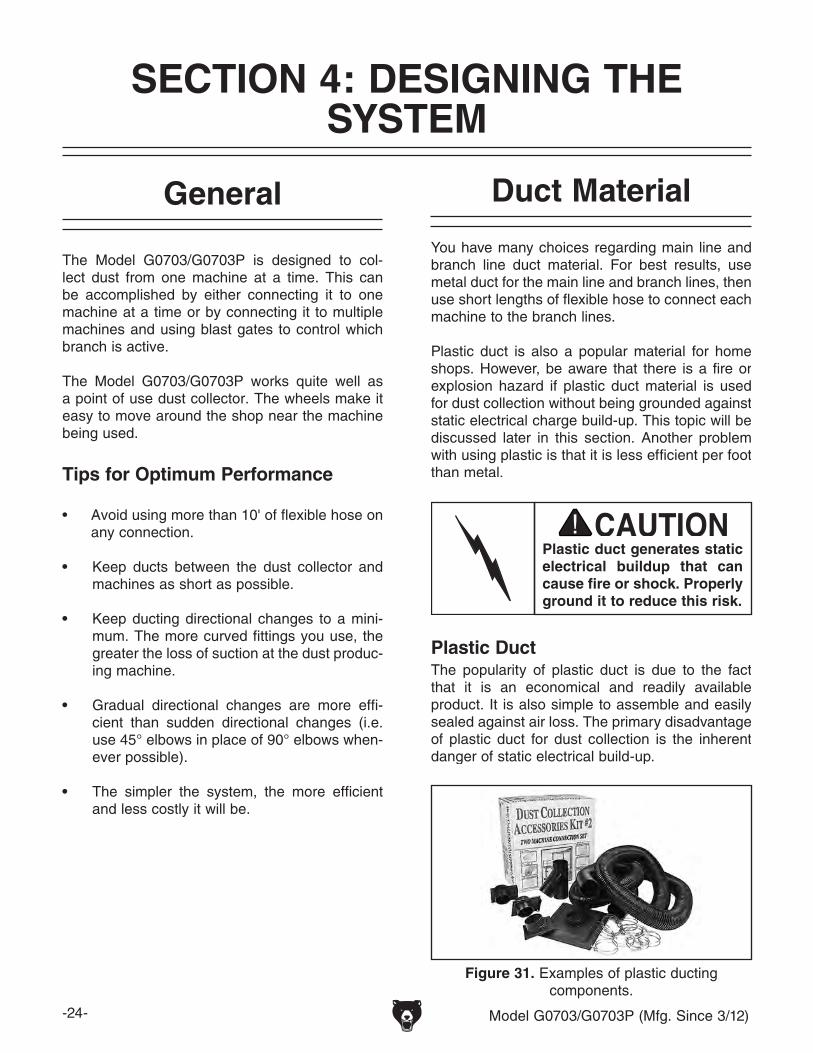
Plastic Duct
Figure 31. Examples of plastic ducting components.
The popularity of plastic duct is due to the fact that it is an economical and readily available product. It is also simple to assemble and easily sealed against air loss. The primary disadvantage of plastic duct for dust collection is the inherent danger of static electrical build-up.
The Model G0703/G0703P is designed to col-lect dust from one machine at a time. This can be accomplished by either connecting it to one machine at a time or by connecting it to multiple machines and using blast gates to control which branch is active.
The Model G0703/G0703P works quite well as a point of use dust collector. The wheels make it easy to move around the shop near the machine being used.
Tips for Optimum Performance
• Avoid using more than 10' of flexible hose on any connection.
• Keep ducts between the dust collector and machines as short as possible.
• Keep ducting directional changes to a mini-mum. The more curved fittings you use, the greater the loss of suction at the dust produc-ing machine.
• Gradual directional changes are more effi-cient than sudden directional changes (i.e. use 45° elbows in place of 90° elbows when-ever possible).
• The simpler the system, the more efficient and less costly it will be.
Model G0703/G0703P (Mfg. Since 3/12) -25-
There are a number of options when it comes to metal duct, but metal duct that is specially manu-factured for dust collection is the best choice. When selecting your metal duct, choose high quality metal duct with smooth welded internal seams that will minimize airflow resistance. This type of duct usually connects to other ducts or elbows with a simple, self-sealing clamp, is very quick and easy to assemble, and can be readily dismantled and re-installed. This is espe-cially important if you ever need to change things around in your shop or add more tools.
Avoid inferior metal duct that requires you to cut it to length and snap it together. This type of duct is time consuming to install because it requires you to seal all the seams with silicone and screw the components on the ends with sheet metal screws. Another disadvantage is the rough internal seams and crimped ends that unavoidably increase static pressure loss.
There are also many kinds of pure plastic flexible hose, such as non-perforated drainage type hose and dryer vent hose. Drainage type hose, while being economical, does not quite have the flex-ibility required for dust collection. The inside of the duct is also deeply corrugated and can increase the static pressure loss by as much as 50% over smooth wall duct. Dryer vent hose, while being completely flexible, is non-resistant to abrasion and has a tendency to collapse in a negative pressure system. We DO NOT recommend using dryer vent hose in your dust collection system.
If using flex-hose, you should choose one of the many types that are designed specifically for the movement of solid particles, i.e. dust, grains, and plastics. However, the cost of specifically designed flexible duct can vary greatly. Grizzly offers polyethylene hose, which is well suited for the removal of particulate matter, especially saw-dust, since it is durable and completely flexible. Polyethylene is also very economical and avail-able in a wide variety of diameters and lengths for most applications.
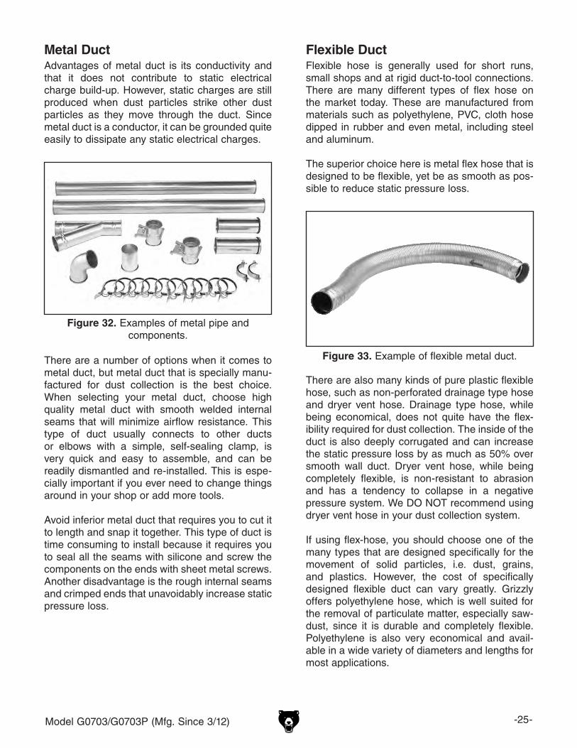
Figure 33. Example of flexible metal duct.
Flexible DuctFlexible hose is generally used for short runs, small shops and at rigid duct-to-tool connections. There are many different types of flex hose on the market today. These are manufactured from materials such as polyethylene, PVC, cloth hose dipped in rubber and even metal, including steel and aluminum.
The superior choice here is metal flex hose that is designed to be flexible, yet be as smooth as pos-sible to reduce static pressure loss.
Metal DuctAdvantages of metal duct is its conductivity and that it does not contribute to static electrical charge build-up. However, static charges are still produced when dust particles strike other dust particles as they move through the duct. Since metal duct is a conductor, it can be grounded quite easily to dissipate any static electrical charges.
Figure 32. Examples of metal pipe and components.
-26- Model G0703/G0703P (Mfg. Since 3/12)
System Design Step 3. Sketch a Basic Duct Layout
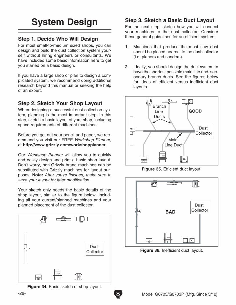
Step 1. Decide Who Will DesignFor most small-to-medium sized shops, you can design and build the dust collection system your-self without hiring engineers or consultants. We have included some basic information here to get you started on a basic design.
If you have a large shop or plan to design a com-plicated system, we recommend doing additional research beyond this manual or seeking the help of an expert.
Dust Collector
Figure 34. Basic sketch of shop layout.
Step 2. Sketch Your Shop LayoutWhen designing a successful dust collection sys-tem, planning is the most important step. In this step, sketch a basic layout of your shop, including space requirements of different machines.
Before you get out your pencil and paper, we rec-ommend you visit our FREE Workshop Planner, at http://www.grizzly.com/workshopplanner.
Our Workshop Planner will allow you to quickly and easily design and print a basic shop layout. Don't worry, non-Grizzly brand machines can be substituted with Grizzly machines for layout pur-poses. Note: After you're finished, make sure to save your layout for later modification.
Your sketch only needs the basic details of the shop layout, similar to the figure below, includ-ing all your current/planned machines and your planned placement of the dust collector.
Figure 35. Efficient duct layout.
Main Line Duct
BranchLine Ducts
GOOD
Dust Collector
Figure 36. Inefficient duct layout.
BAD
Dust Collector
For the next step, sketch how you will connect your machines to the dust collector. Consider these general guidelines for an efficient system:
1. Machines that produce the most saw dust should be placed nearest to the dust collector (i.e. planers and sanders).
2. Ideally, you should design the duct system to have the shortest possible main line and sec-ondary branch ducts. See the figures below for ideas of efficient versus inefficient duct layouts.
Model G0703/G0703P (Mfg. Since 3/12) -27-
3. Directional changes should be kept to a mini-mum. The more directional change fittings you use directly increases the overall resis-tance to airflow.
4. Gradual directional changes are more effi-cient than sudden directional changes (i.e. use the largest corner radius possible when changing hose or pipe direction).
5. Each individual branch line should have a blast gate immediately after the branch to control suction from one machine to another.
6. The simpler the system, the more efficient and less costly it will be.
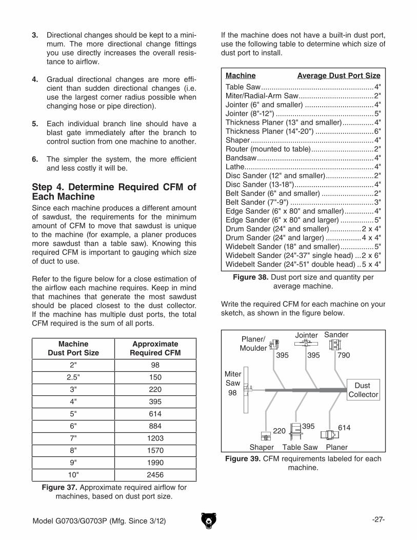
Step 4. Determine Required CFM of Each MachineSince each machine produces a different amount of sawdust, the requirements for the minimum amount of CFM to move that sawdust is unique to the machine (for example, a planer produces more sawdust than a table saw). Knowing this required CFM is important to gauging which size of duct to use.
Refer to the figure below for a close estimation of the airflow each machine requires. Keep in mind that machines that generate the most sawdust should be placed closest to the dust collector. If the machine has multiple dust ports, the total CFM required is the sum of all ports.
Figure 37. Approximate required airflow for machines, based on dust port size.
Machine Dust Port Size
Approximate Required CFM
2" 98
2.5" 150
3" 220
4" 395
5" 614
6" 884
7" 1203
8" 1570
9" 1990
10" 2456
If the machine does not have a built-in dust port, use the following table to determine which size of dust port to install.
Figure 38. Dust port size and quantity per average machine.
Machine Average Dust Port Size
Table Saw ......................................................4"Miter/Radial-Arm Saw ....................................2"Jointer (6" and smaller) .................................4"Jointer (8"-12") ...............................................5"Thickness Planer (13" and smaller) ...............4"Thickness Planer (14"-20") ............................6"Shaper ...........................................................4"Router (mounted to table) ..............................2"Bandsaw ........................................................4"Lathe ..............................................................4"Disc Sander (12" and smaller) .......................2"Disc Sander (13-18") ......................................4"Belt Sander (6" and smaller) .........................2"Belt Sander (7"-9") ........................................3"Edge Sander (6" x 80" and smaller) ..............4"Edge Sander (6" x 80" and larger) ................5"Drum Sander (24" and smaller) ...............2 x 4"Drum Sander (24" and larger) .................4 x 4"Widebelt Sander (18" and smaller) ................5"Widebelt Sander (24"-37" single head) ...2 x 6"Widebelt Sander (24"-51" double head) ..5 x 4"
Figure 39. CFM requirements labeled for each machine.
395
395
614
790395
220
98
Table Saw
Planer/Moulder
MiterSaw
Jointer Sander
PlanerShaper
Dust Collector
Write the required CFM for each machine on your sketch, as shown in the figure below.
-28- Model G0703/G0703P (Mfg. Since 3/12)
Determining Main Line Duct Size
Figure 40. Main line size labeled on sketch.
395
395
614
790395
220
98
Dust Collector
5" 6" 7"
Table Saw
Planer/Moulder
MiterSaw
Jointer Sander
PlanerShaper
Figure 41. Branch line duct sizes labeled.
395
395
614
790395
220
98
4"
4"
4" 6"
4" 4" 5"
5" 6" 7"
Table Saw
MiterSaw
Jointer Sander
PlanerShaper
Planer/Moulder
Dust Collector
The general rule of thumb for a main line duct is that the velocity of the airflow must not fall below 3500 FPM.
For small/medium sized shops, using the inlet size of the dust collector as the main line duct size will usually keep the air velocity above 3500 FPM and, depending on your system, will allow you to keep multiple branches open at one time.
Mark your drawing, as shown in the figure below, but using the inlet size for your dust collector as the main line.
The general rule of thumb for a branch line duct is that the velocity of the airflow must not fall below 4000 FPM.
For small/medium sized shops, using the dust port size from the machine as the branch line duct size will achieve the correct velocity in most appli-cations. However, if the dust port on the machine is smaller than 4", make the branch line 4" and neck the line down right before the dust port.
Note: Systems with powerful dust collectors work better if multiple blast gates are left open. This also allows you to run two machines at once. Experiment with different combinations of blast gates open/closed to find the best results for your system.
Write your determined branch line sizes on your drawing, as shown in the following figure.
Determining Branch Line Duct Size
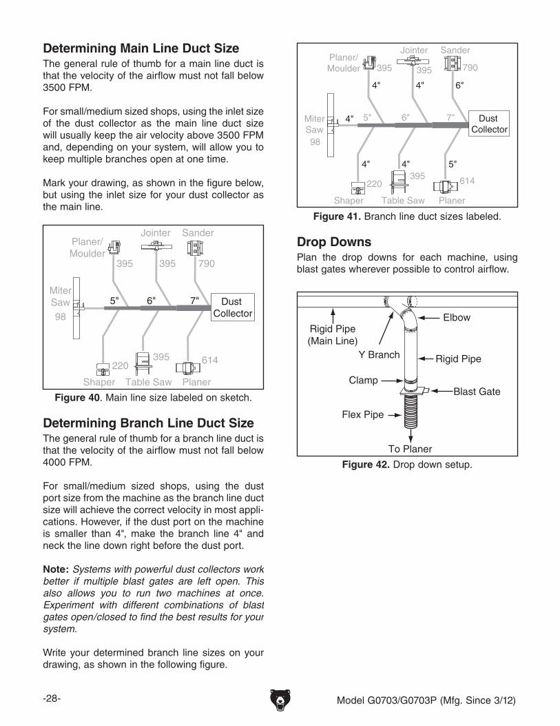
Plan the drop downs for each machine, using blast gates wherever possible to control airflow.
To Planer
Blast Gate
Flex Pipe
Rigid Pipe
Rigid Pipe (Main Line)
Elbow
Clamp
Y Branch
Figure 42. Drop down setup.
Drop Downs
Model G0703/G0703P (Mfg. Since 3/12) -29-
Figure 44. Static pressure loss tables.
Duct Dia.
Approximate Static Pressure
Loss Per Foot of Rigid Pipe
Approximate Static Pressure Loss Per Foot of Flex Pipe
Main Lines
at 3500 FPM
Branch Lines
at 4000 FPM
Main Lines
at 3500 FPM
Branch Lines
at 4000 FPM
2" 0.091 0.122 0.35 0.453
2.5" 0.08 0.107 0.306 0.397
3" 0.071 0.094 0.271 0.352
4" 0.057 0.075 0.215 0.28
5" 0.046 0.059 0.172 0.225
6" 0.037 0.047 0.136 0.18
7" 0.029 0.036 0.106 0.141
8" 0.023 0.027 0.08 0.108
9" 0.017 0.019 0.057 0.079
Fitting Dia.
90˚ Elbow
45˚ Elbow
45˚ Wye(Y)
90˚ Wye(Y)
3" 0.47 0.235 0.282 0.188
4" 0.45 0.225 0.375 0.225
5" 0.531 0.266 0.354 0.236
6" 0.564 0.282 0.329 0.235
7" 0.468 0.234 0.324 0.216
8" 0.405 0.203 0.297 0.189
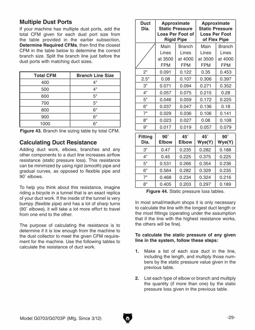
In most small/medium shops it is only necessary to calculate the line with the longest duct length or the most fittings (operating under the assumption that if the line with the highest resistance works, the others will be fine).
To calculate the static pressure of any given line in the system, follow these steps:
1. Make a list of each size duct in the line, including the length, and multiply those num-bers by the static pressure value given in the previous table.
2. List each type of elbow or branch and multiply the quantity (if more than one) by the static pressure loss given in the previous table.
Adding duct work, elbows, branches and any other components to a duct line increases airflow resistance (static pressure loss). This resistance can be minimized by using rigid (smooth) pipe and gradual curves, as opposed to flexible pipe and 90˚ elbows.
To help you think about this resistance, imagine riding a bicycle in a tunnel that is an exact replica of your duct work. If the inside of the tunnel is very bumpy (flexible pipe) and has a lot of sharp turns (90˚ elbows), it will take a lot more effort to travel from one end to the other.
The purpose of calculating the resistance is to determine if it is low enough from the machine to the dust collector to meet the given CFM require-ment for the machine. Use the following tables to calculate the resistance of duct work.
Calculating Duct Resistance
Figure 43. Branch line sizing table by total CFM.
Total CFM Branch Line Size
400 4"
500 4"
600 5"
700 5"
800 6"
900 6"
1000 6"
Multiple Dust PortsIf your machine has multiple dust ports, add the total CFM given for each dust port size from the table provided in the earlier subsection, Determine Required CFMs, then find the closest CFM in the table below to determine the correct branch size. Split the branch line just before the dust ports with matching duct sizes.
-30- Model G0703/G0703P (Mfg. Since 3/12)
Figure 45. Additional factors affecting static pressure.
Figure 46. Totaling static pressure numbers.
Main Line6" Rigid Pipe (0.037) at 20' ................ 0.740
Branch Line4" Rigid Pipe (0.075) at 10' ................ 0.7504" Flex Pipe (0.28) at 5' ........................ 1.400
Elbows/Branches6" 45˚ Y-Branch ................................ 0.3294" 45˚ Elbow ........................................ 0.225
Additional FactorsSeasoned Filter ................................ 1.000
Total Static Pressure Loss ................ 4.444
Additional Factors Static Pressure
Seasoned (well used)
Dust Collection Filter1"
Entry Loss at Large
Machine Hood2"
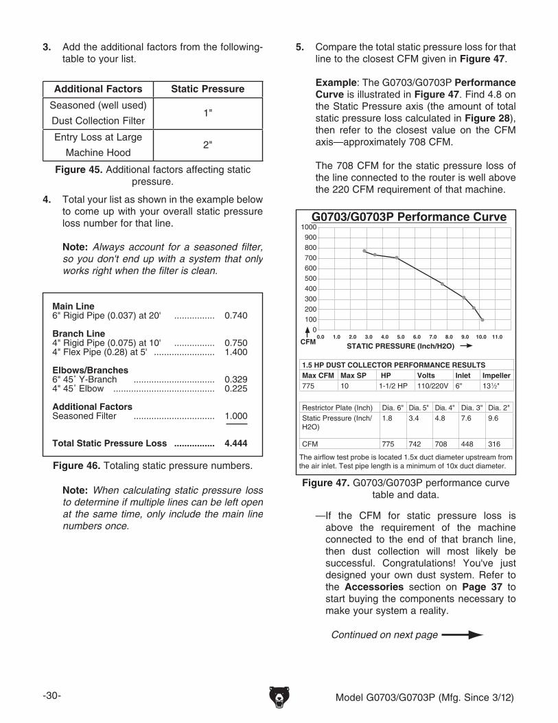
4. Total your list as shown in the example below to come up with your overall static pressure loss number for that line.
Note: Always account for a seasoned filter, so you don't end up with a system that only works right when the filter is clean.
Note: When calculating static pressure loss to determine if multiple lines can be left open at the same time, only include the main line numbers once.
3. Add the additional factors from the following-table to your list.
5. Compare the total static pressure loss for that line to the closest CFM given in Figure 47.
Example: The G0703/G0703P Performance Curve is illustrated in Figure 47. Find 4.8 on the Static Pressure axis (the amount of total static pressure loss calculated in Figure 28), then refer to the closest value on the CFM axis—approximately 708 CFM.
The 708 CFM for the static pressure loss of the line connected to the router is well above the 220 CFM requirement of that machine.
— If the CFM for static pressure loss is above the requirement of the machine connected to the end of that branch line, then dust collection will most likely be successful. Congratulations! You've just designed your own dust system. Refer to the Accessories section on Page 37 to start buying the components necessary to make your system a reality.
The airflow test probe is located 1.5x duct diameter upstream from the air inlet. Test pipe length is a minimum of 10x duct diameter.
G0703/G0703P Performance Curve1000900800700600500400300200100
00.0 1.0 2.0 3.0 4.0 5.0 6.0 7.0 8.0 9.0 10.0 11.0
CFM STATIC PRESSURE (Inch/H2O)
1.5 HP DUST COLLECTOR PERFORMANCE RESULTSMax CFM Max SP HP Volts Inlet Impeller775 10 1-1/2 HP 110/220V 6" 13 1⁄2"
Restrictor Plate (Inch) Dia. 6" Dia. 5" Dia. 4" Dia. 3" Dia. 2"Static Pressure (Inch/H2O)
1.8 3.4 4.8 7.6 9.6
CFM 775 742 708 448 316
Figure 47. G0703/G0703P performance curve table and data.
Performance curve
Model G0703/G0703P (Mfg. Since 3/12) -31-
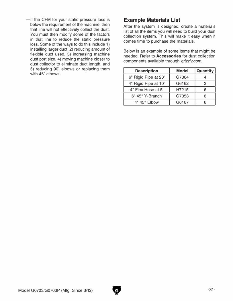
—If the CFM for your static pressure loss is below the requirement of the machine, then that line will not effectively collect the dust. You must then modify some of the factors in that line to reduce the static pressure loss. Some of the ways to do this include 1) installing larger duct, 2) reducing amount of flexible duct used, 3) increasing machine dust port size, 4) moving machine closer to dust collector to eliminate duct length, and 5) reducing 90˚ elbows or replacing them with 45˚ elbows.
Description Model Quantity
6" Rigid Pipe at 20' G7364 4
4" Rigid Pipe at 10' G6162 2
4" Flex Hose at 5' H7215 6
6" 45° Y-Branch G7353 6
4" 45° Elbow G6167 6
Example Materials ListAfter the system is designed, create a materials list of all the items you will need to build your dust collection system. This will make it easy when it comes time to purchase the materials.
Below is an example of some items that might be needed. Refer to Accessories for dust collection components available through grizzly.com.
-32- Model G0703/G0703P (Mfg. Since 3/12)
System Grounding
Since plastic hose is abundant, relatively inex-pensive, easily assembled and air tight, it is a very popular material for conveying dust from woodworking machines to the dust collector. We recommend using flexible hose (flex-hose) to connect the woodworking machine to the dust collector. However, plastic flex-hose and plastic duct are an insulator, and dust particles moving against the walls of the plastic duct create a static electrical build up. This charge will build until it discharges to a ground. If a grounding medium is not available to prevent static electrical build up, the electrical charge will arc to the nearest grounded source. This electrical discharge may cause an explosion and subsequent fire inside the system.
To protect against static electrical build up inside a non-conducting duct, a bare copper wire should be placed inside the duct along its length and grounded to the dust collector. You must also confirm that the dust collector is continuously grounded through the electrical circuit to the elec-tric service panel.
If you connect the dust collector to more than one machine by way of a non-conducting branching duct system and blast gates, the system must still be grounded as mentioned above. We recom-mend inserting a continuous bare copper ground wire inside the entire duct system and attaching the wire to each grounded woodworking machine and dust collector.
Be sure that you extend the bare copper wire down all branches of the system. Do not forget to connect the wires to each other with wire nuts when two branches meet at a “Y” or “T” connec-tion.
Ensure that the entire system is grounded. If using plastic blast gates to direct air flow, the ground-ing wire must be jumped (see the figure below) around the blast gate without interruption to the grounding system.
We also recommend wrapping the outside of all plastic ducts with bare copper wire to ground the outside of the system against static electrical build up. Wire connections at Y’s and T’s should be made with wire nuts.
Attach the bare ground wire to each stationary woodworking machine and attach to the dust collector frame with a ground screw as shown in the figure below. Ensure that each machine is continuously grounded to the grounding terminal in your electric service panel.
External Ground Wire
Internal Ground Wire
Flex-Hose
Ground Screw
Figure 49. Flex-hose grounded to machine.
Plastic BlastGate
CopperGround Wire
Metal Duct
Figure 48. Ground jumper wire when using plastic blast gates and metal duct.
Always guard against stat-ic electrical build up by grounding all dust collec-tion lines.
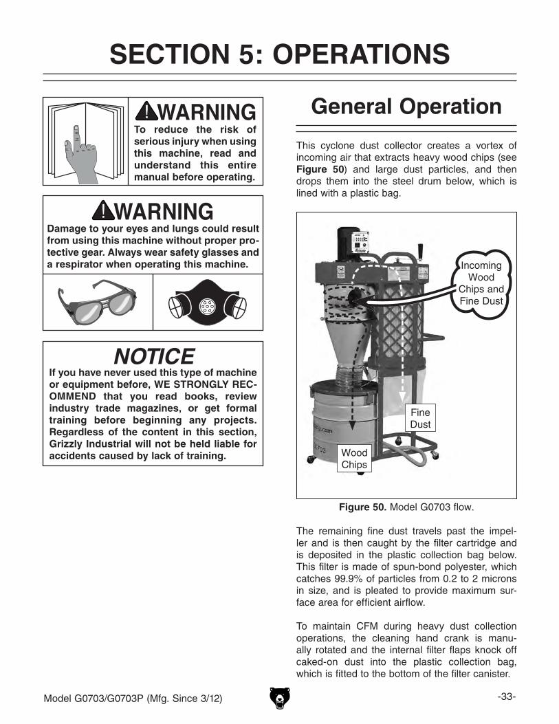
Model G0703/G0703P (Mfg. Since 3/12) -33-
SECTION 5: OPERATIONS
Damage to your eyes and lungs could result from using this machine without proper pro-tective gear. Always wear safety glasses and a respirator when operating this machine.
To reduce the risk of serious injury when using this machine, read and understand this entire manual before operating.
NOTICEIf you have never used this type of machine or equipment before, WE STRONGLY REC-OMMEND that you read books, review industry trade magazines, or get formal training before beginning any projects. Regardless of the content in this section, Grizzly Industrial will not be held liable for accidents caused by lack of training.
General Operation
This cyclone dust collector creates a vortex of incoming air that extracts heavy wood chips (see Figure 50) and large dust particles, and then drops them into the steel drum below, which is lined with a plastic bag.
Figure 50. Model G0703 flow.
The remaining fine dust travels past the impel-ler and is then caught by the filter cartridge and is deposited in the plastic collection bag below. This filter is made of spun-bond polyester, which catches 99.9% of particles from 0.2 to 2 microns in size, and is pleated to provide maximum sur-face area for efficient airflow.
To maintain CFM during heavy dust collection operations, the cleaning hand crank is manu-ally rotated and the internal filter flaps knock off caked-on dust into the plastic collection bag, which is fitted to the bottom of the filter canister.
Incoming Wood
Chips and Fine Dust
Fine Dust
WoodChips
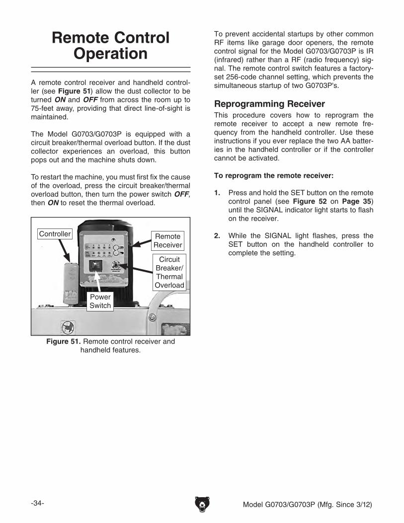
-34- Model G0703/G0703P (Mfg. Since 3/12)
Remote Control Operation
A remote control receiver and handheld control-ler (see Figure 51) allow the dust collector to be turned ON and OFF from across the room up to 75-feet away, providing that direct line-of-sight is maintained.
The Model G0703/G0703P is equipped with a circuit breaker/thermal overload button. If the dust collector experiences an overload, this button pops out and the machine shuts down.
To restart the machine, you must first fix the cause of the overload, press the circuit breaker/thermal overload button, then turn the power switch OFF, then ON to reset the thermal overload.
Figure 51. Remote control receiver and handheld features.
Remote Receiver
Controller
To prevent accidental startups by other common RF items like garage door openers, the remote control signal for the Model G0703/G0703P is IR (infrared) rather than a RF (radio frequency) sig-nal. The remote control switch features a factory-set 256-code channel setting, which prevents the simultaneous startup of two G0703P's.
To reprogram the remote receiver:
1. Press and hold the SET button on the remote control panel (see Figure 52 on Page 35) until the SIGNAL indicator light starts to flash on the receiver.
2. While the SIGNAL light flashes, press the SET button on the handheld controller to complete the setting.
This procedure covers how to reprogram the remote receiver to accept a new remote fre-quency from the handheld controller. Use these instructions if you ever replace the two AA batter-ies in the handheld controller or if the controller cannot be activated.
Reprogramming Receiver
Circuit Breaker/Thermal Overload
Power Switch
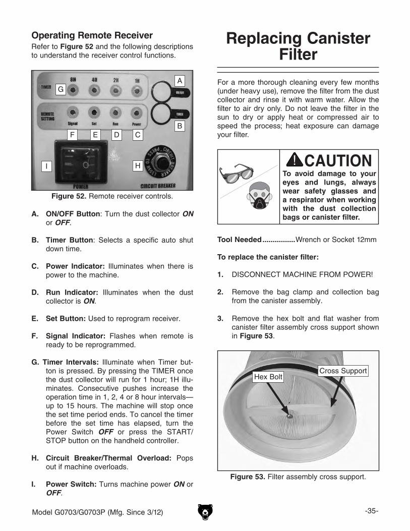
Model G0703/G0703P (Mfg. Since 3/12) -35-
Operating Remote ReceiverRefer to Figure 52 and the following descriptions to understand the receiver control functions.
A. ON/OFF Button: Turn the dust collector ON or OFF.
B. Timer Button: Selects a specific auto shut down time.
C. Power Indicator: Illuminates when there is power to the machine.
D. Run Indicator: Illuminates when the dust collector is ON.
E. Set Button: Used to reprogram receiver.
F. Signal Indicator: Flashes when remote is ready to be reprogrammed.
G. Timer Intervals: Illuminate when Timer but-ton is pressed. By pressing the TIMER once the dust collector will run for 1 hour; 1H illu-minates. Consecutive pushes increase the operation time in 1, 2, 4 or 8 hour intervals—up to 15 hours. The machine will stop once the set time period ends. To cancel the timer before the set time has elapsed, turn the Power Switch OFF or press the START/STOP button on the handheld controller.
H. Circuit Breaker/Thermal Overload: Pops out if machine overloads.
I. Power Switch: Turns machine power ON or OFF.
Figure 52. Remote receiver controls.
A
B
I
CF
H
E D
GFor a more thorough cleaning every few months (under heavy use), remove the filter from the dust collector and rinse it with warm water. Allow the filter to air dry only. Do not leave the filter in the sun to dry or apply heat or compressed air to speed the process; heat exposure can damage your filter.
To avoid damage to your eyes and lungs, always wear safety glasses and a respirator when working with the dust collection bags or canister filter.
Tool Needed ................Wrench or Socket 12mm
To replace the canister filter:
1. DISCONNECT MACHINE FROM POWER!
2. Remove the bag clamp and collection bag from the canister assembly.
Replacing Canister Filter
3. Remove the hex bolt and flat washer from canister filter assembly cross support shown in Figure 53.
Figure 53. Filter assembly cross support.
Hex BoltCross Support
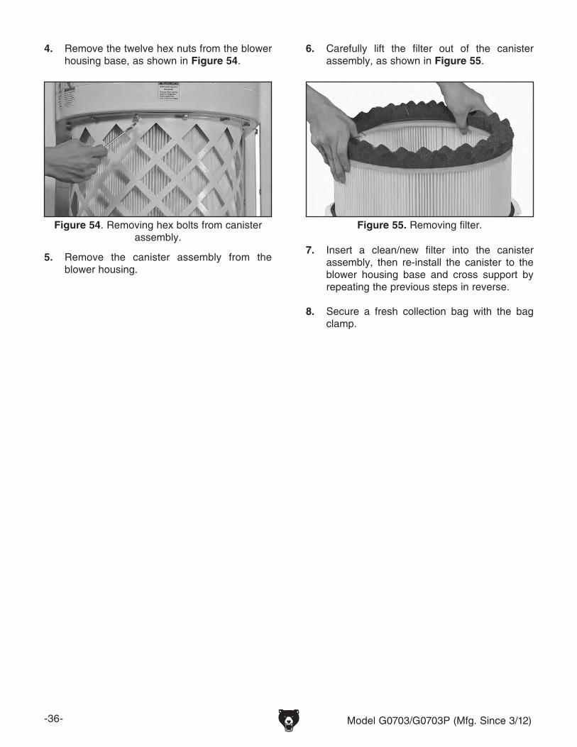
-36- Model G0703/G0703P (Mfg. Since 3/12)
4. Remove the twelve hex nuts from the blower housing base, as shown in Figure 54.
Figure 54. Removing hex bolts from canister assembly.
5. Remove the canister assembly from the blower housing.
6. Carefully lift the filter out of the canister assembly, as shown in Figure 55.
7. Insert a clean/new filter into the canister assembly, then re-install the canister to the blower housing base and cross support by repeating the previous steps in reverse.
8. Secure a fresh collection bag with the bag clamp.
Figure 55. Removing filter.
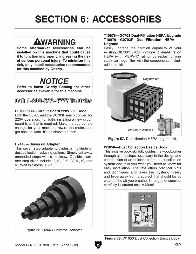
Model G0703/G0703P (Mfg. Since 3/12) -37-
SECTION 6: ACCESSORIESACCESSORIES
P0703P088—Circuit Board 220V 256 CodeBoth the G0703 and the G0703P easily convert for 220V operation. For both, installing a new circuit board is all that is required. Make the appropriate change for your machine, rewire the motor, and get back to work. It’s as simple as that!
Some aftermarket accessories can be installed on this machine that could cause it to function improperly, increasing the risk of serious personal injury. To minimize this risk, only install accessories recommended for this machine by Grizzly.
NOTICERefer to latest Grizzly Catalog for other accessories available for this machine.
H2443—Universal AdapterThis seven step adapter provides a multitude of dust collection reducing options. Simply cut away unneeded steps with a hacksaw. Outside diam-eter step sizes include 1", 2", 2.5", 3", 4", 5", and 6". Wall thickness is 1⁄8".
Figure 56. H2443 Universal Adapter.
T10878—G0703 Dual-Filtration HEPA UpgradeT10879—G0703P Dual-Filtration HEPA UpgradeEasily upgrade the filtration capability of your existing G0703/G0703P cyclone to dual-filtration HEPA (with MERV-17 rating) by replacing your stock cartridge filter with the components includ-ed in this kit.
Figure 57. Dual-filtration HEPA upgrade kit.
Kit Shown Installed
Upgrade Kit
W1050—Dust Collection Basics BookThis incisive book skillfully guides the woodworker through all the steps necessary in the design and construction of an efficient central dust collection system and tells you what you need to know for easy installation. The text offers practical hints and techniques and takes the mystery, misery and hype away from a subject that should be as clear as the air you breathe. 64 pages of concise, carefully illustrated text. A Must!
Figure 58. W1050 Dust Collection Basics Book.
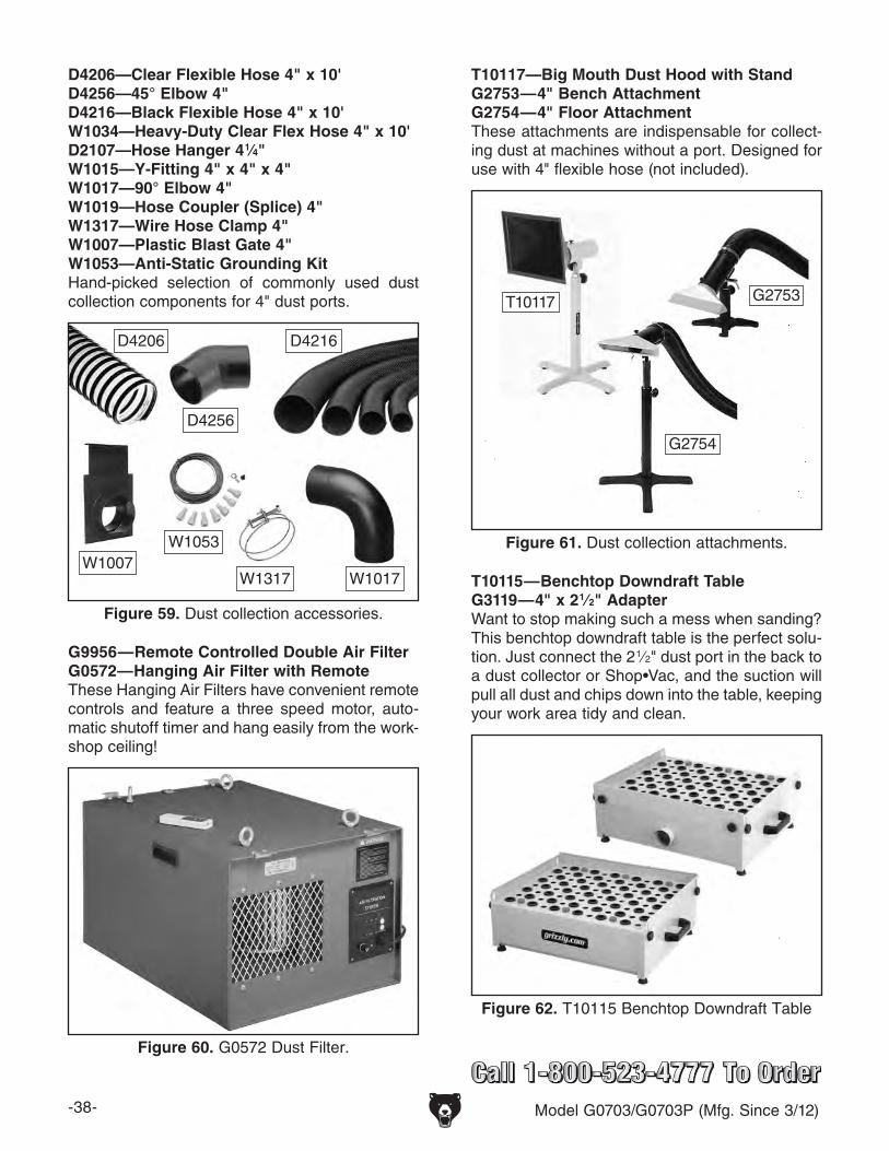
-38- Model G0703/G0703P (Mfg. Since 3/12)
T10115—Benchtop Downdraft TableG3119—4" x 2 1⁄2" AdapterWant to stop making such a mess when sanding? This benchtop downdraft table is the perfect solu-tion. Just connect the 2 1⁄2" dust port in the back to a dust collector or Shop•Vac, and the suction will pull all dust and chips down into the table, keeping your work area tidy and clean.
Figure 62. T10115 Benchtop Downdraft Table
D4206—Clear Flexible Hose 4" x 10'D4256—45° Elbow 4"D4216—Black Flexible Hose 4" x 10'W1034—Heavy-Duty Clear Flex Hose 4" x 10'D2107—Hose Hanger 4 1⁄4"W1015—Y-Fitting 4" x 4" x 4"W1017—90° Elbow 4"W1019—Hose Coupler (Splice) 4"W1317—Wire Hose Clamp 4"W1007—Plastic Blast Gate 4"W1053—Anti-Static Grounding KitHand-picked selection of commonly used dust collection components for 4" dust ports.
Figure 59. Dust collection accessories.
D4206
D4256
W1317
D4216
W1007W1017
W1053 Figure 61. Dust collection attachments.
T10117—Big Mouth Dust Hood with StandG2753—4" Bench AttachmentG2754—4" Floor AttachmentThese attachments are indispensable for collect-ing dust at machines without a port. Designed for use with 4" flexible hose (not included).
T10117 G2753
G2754
G9956—Remote Controlled Double Air FilterG0572—Hanging Air Filter with RemoteThese Hanging Air Filters have convenient remote controls and feature a three speed motor, auto-matic shutoff timer and hang easily from the work-shop ceiling!
Figure 60. G0572 Dust Filter.
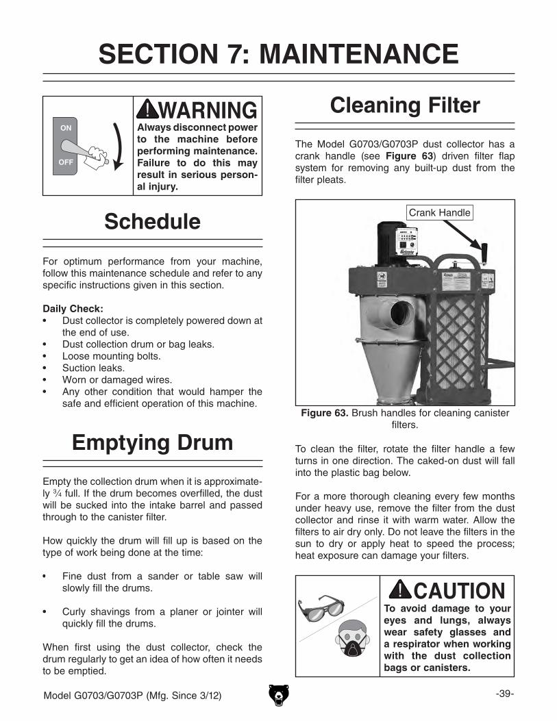
Model G0703/G0703P (Mfg. Since 3/12) -39-
SECTION 7: MAINTENANCE
Always disconnect power to the machine before performing maintenance. Failure to do this may result in serious person-al injury.
For optimum performance from your machine, follow this maintenance schedule and refer to any specific instructions given in this section.
Daily Check:• Dust collector is completely powered down at
the end of use.• Dust collection drum or bag leaks.• Loose mounting bolts.• Suction leaks.• Worn or damaged wires.• Any other condition that would hamper the
safe and efficient operation of this machine.
Schedule
Emptying Drum
Empty the collection drum when it is approximate-ly 3⁄4 full. If the drum becomes overfilled, the dust will be sucked into the intake barrel and passed through to the canister filter.
How quickly the drum will fill up is based on the type of work being done at the time:
• Fine dust from a sander or table saw will slowly fill the drums.
• Curly shavings from a planer or jointer will quickly fill the drums.
When first using the dust collector, check the drum regularly to get an idea of how often it needs to be emptied.
The Model G0703/G0703P dust collector has a crank handle (see Figure 63) driven filter flap system for removing any built-up dust from the filter pleats.
Cleaning Filter
To avoid damage to your eyes and lungs, always wear safety glasses and a respirator when working with the dust collection bags or canisters.
To clean the filter, rotate the filter handle a few turns in one direction. The caked-on dust will fall into the plastic bag below.
For a more thorough cleaning every few months under heavy use, remove the filter from the dust collector and rinse it with warm water. Allow the filters to air dry only. Do not leave the filters in the sun to dry or apply heat to speed the process; heat exposure can damage your filters.
Figure 63. Brush handles for cleaning canister filters.
Crank Handle
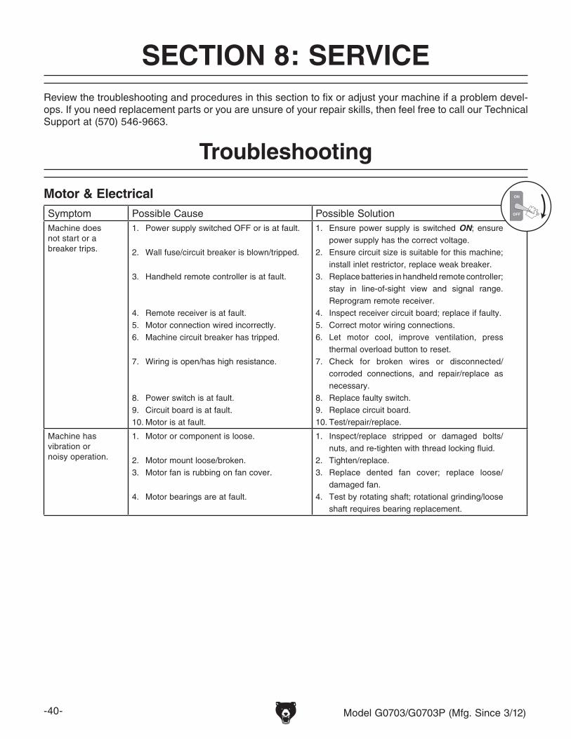
-40- Model G0703/G0703P (Mfg. Since 3/12)
Review the troubleshooting and procedures in this section to fix or adjust your machine if a problem devel-ops. If you need replacement parts or you are unsure of your repair skills, then feel free to call our Technical Support at (570) 546-9663.
SECTION 8: SERVICE
Troubleshooting
Motor & ElectricalSymptom Possible Cause Possible SolutionMachine does not start or a breaker trips.
1. Power supply switched OFF or is at fault.
2. Wall fuse/circuit breaker is blown/tripped.
3. Handheld remote controller is at fault.
4. Remote receiver is at fault.5. Motor connection wired incorrectly.6. Machine circuit breaker has tripped.
7. Wiring is open/has high resistance.
8. Power switch is at fault.9. Circuit board is at fault.10. Motor is at fault.
1. Ensure power supply is switched ON; ensure power supply has the correct voltage.
2. Ensure circuit size is suitable for this machine; install inlet restrictor, replace weak breaker.
3. Replace batteries in handheld remote controller; stay in line-of-sight view and signal range. Reprogram remote receiver.
4. Inspect receiver circuit board; replace if faulty.5. Correct motor wiring connections.6. Let motor cool, improve ventilation, press
thermal overload button to reset.7. Check for broken wires or disconnected/
corroded connections, and repair/replace as necessary.
8. Replace faulty switch.9. Replace circuit board.10. Test/repair/replace.
Machine has vibration or noisy operation.
1. Motor or component is loose.
2. Motor mount loose/broken.3. Motor fan is rubbing on fan cover.
4. Motor bearings are at fault.
1. Inspect/replace stripped or damaged bolts/nuts, and re-tighten with thread locking fluid.
2. Tighten/replace.3. Replace dented fan cover; replace loose/
damaged fan.4. Test by rotating shaft; rotational grinding/loose
shaft requires bearing replacement.
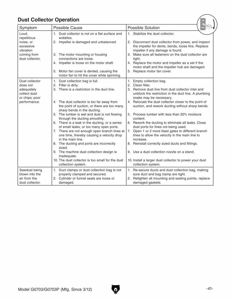
Model G0703/G0703P (Mfg. Since 3/12) -41-
Symptom Possible Cause Possible SolutionLoud, repetitious noise, or excessive vibration coming from dust collector.
1. Dust collector is not on a flat surface and wobbles.
2. Impeller is damaged and unbalanced.
3. The motor mounting or housing connections are loose.
4. Impeller is loose on the motor shaft.
5. Motor fan cover is dented, causing the motor fan to hit the cover while spinning.
1. Stabilize the dust collector.
2. Disconnect dust collector from power, and inspect the impeller for dents, bends, loose fins. Replace impeller if any damage is found.
3. Make sure all fasteners on the dust collector are tight.
4. Replace the motor and impeller as a set if the motor shaft and the impeller hub are damaged.
5. Replace motor fan cover.
Dust collector does not adequately collect dust or chips; poor performance.
1. Dust collection bag is full.2. Filter is dirty.3. There is a restriction in the duct line.
4. The dust collector is too far away from the point of suction, or there are too many sharp bends in the ducting.
5. The lumber is wet and dust is not flowing through the ducting smoothly.
6. There is a leak in the ducting, or a series of small leaks, or too many open ports.
7. There are not enough open branch lines at one time, thereby causing a velocity drop in the main line.
8. The ducting and ports are incorrectly sized.
9. The machine dust collection design is inadequate.
10. The dust collector is too small for the dust collection system.
1. Empty collection bag.2. Clean filter.3. Remove dust line from dust collector inlet and
unblock the restriction in the duct line. A plumbing snake may be necessary.
4. Relocate the dust collector closer to the point of suction, and rework ducting without sharp bends.
5. Process lumber with less than 20% moisture content.
6. Rework the ducting to eliminate all leaks. Close dust ports for lines not being used.
7. Open 1 or 2 more blast gates to different branch lines to allow the velocity in the main line to increase.
8. Reinstall correctly sized ducts and fittings.
9. Use a dust collection nozzle on a stand.
10. Install a larger dust collector to power your dust collection system.
Sawdust being blown into the air from the dust collector.
1. Duct clamps or dust collection bag is not properly clamped and secured.
2. Cylinder or funnel seals are loose or damaged.
1. Re-secure ducts and dust collection bag, making sure duct and bag clamp are tight.
2. Retighten all mounting and sealing points, replace damaged gaskets.
Dust Collector Operation

-42- Model G0703/G0703P (Mfg. Since 3/12)
SHOCK HAZARD. Working on wiring that is con-nected to a power source is extremely dangerous. Touching electrified parts will result in personal injury including but not limited to severe burns, electrocution, or death. Disconnect the power from the machine before servicing electrical com-ponents!
MODIFICATIONS. Modifying the wiring beyond what is shown in the diagram may lead to unpre-dictable results, including serious injury or fire. This includes the installation of unapproved after-market parts.
WIRE CONNECTIONS. All connections must be tight to prevent wires from loosening during machine operation. Double-check all wires dis-connected or connected during any wiring task to ensure tight connections.
CIRCUIT REQUIREMENTS. You MUST follow the requirements at the beginning of this manualwhen connecting your machine to a power source.
WIRE/COMPONENT DAMAGE. Damaged wires or components increase the risk of serious per-sonal injury, fire, or machine damage. If you notice that any wires or components are damaged while performing a wiring task, replace those wires or components.
MOTOR WIRING. The motor wiring shown inthese diagrams is current at the time of printingbut may not match your machine. If you find thisto be the case, use the wiring diagram inside the motor junction box.
CAPACITORS/INVERTERS. Some capacitorsand power inverters store an electrical charge for up to 10 minutes after being disconnected from the power source. To reduce the risk of being shocked, wait at least this long before working on capacitors.
EXPERIENCING DIFFICULTIES. If you are expe-riencing difficulties understanding the information included in this section, contact our Technical Support at (570) 546-9663.
Wiring Safety Instructions
The photos and diagrams included in this section are best viewed in color. You can view these pages in color at www.grizzly.com.
These pages are current at the time of printing. However, in the spirit of improvement, we may make chang-es to the electrical systems of future machines. Compare the manufacture date of your machine to the one stated in this manual, and study this section carefully.
If there are differences between your machine and what is shown in this section, call Technical Support at (570) 546-9663 for assistance BEFORE making any changes to the wiring on your machine. An updated wiring diagram may be available. Note: Please gather the serial number and manufacture date of your machine before calling. This information can be found on the main machine label.
SECTION 9: WIRINGwiring
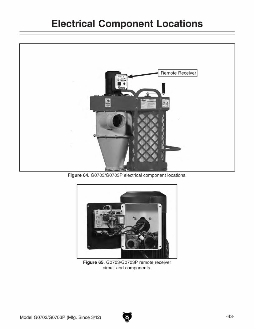
Model G0703/G0703P (Mfg. Since 3/12) -43-
Electrical Component Locations
Figure 64. G0703/G0703P electrical component locations.
Figure 65. G0703/G0703P remote receiver circuit and components.
Remote Receiver
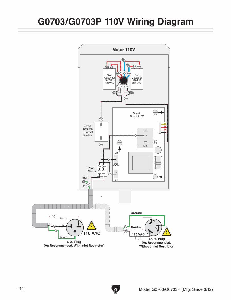
-44- Model G0703/G0703P (Mfg. Since 3/12)
G0703/G0703P 110V Wiring Diagram
Motor 110V
1 23 4
RunCapacitor40MFD250VAC
StartCapacitor300MFD125VAC
Power Switch
Circuit Breaker/ThermalOverload
Circuit Board 110V
L2
L1
COM
M2
M1
GND
Hot
Neutral
Ground
110 VAC
G
WNeutral
Hot
Ground
110 VAC
5-20 Plug(As Recommended, With Inlet Restrictor)
L5-30 Plug(As Recommended,
Without Inlet Restrictor)
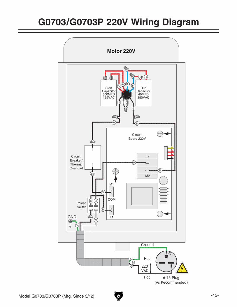
Model G0703/G0703P (Mfg. Since 3/12) -45-
G0703/G0703P 220V Wiring Diagram
Motor 220V
Power Switch
Circuit Breaker/ThermalOverload
Circuit Board 220V
L2
L1
COM
M2
M1
2
RunCapacitor40MFD250VAC
StartCapacitor300MFD125VAC
4
31
Hot
Hot
Ground
6-15 Plug(As Recommended)
220VAC
G
GND
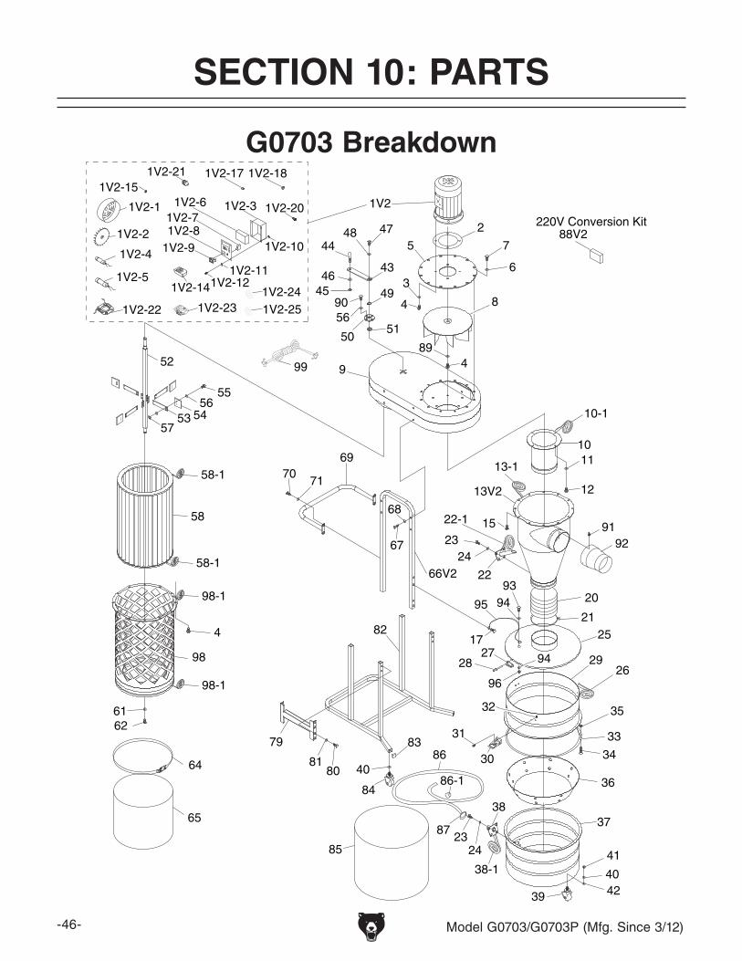
-46- Model G0703/G0703P (Mfg. Since 3/12)
1V2
2
3
4
5
6
7
8
9
10
10-1
11
12
13-1
13V2
15
20
21
22
22-1
25
26
2728 29
30
31
32
33
34
35
36
3738
38-1
39
40
41
42
43
44
4546
4748
49
5051
52
53 54
55
56
57
61
4
98
58-1
58-1
98-1
58
62
64
65
66V2
67
68
6970
71
79
8081
82
83
84
85
86
86-1
87
89
90
9192
939495
96
4
2324
94
17
2423
40
56
99
98-1
1V2-1
1V2-2
1V2-31V2-61V2-71V2-8
1V2-9 1V2-10
1V2-111V2-12
1V2-4
1V2-5
1V2-211V2-15
1V2-22
1V2-241V2-23 1V2-25
1V2-17
1V2-20
1V2-18
1V2-14
220V Conversion Kit88V2
G0703 Breakdown
SECTION 10: PARTS
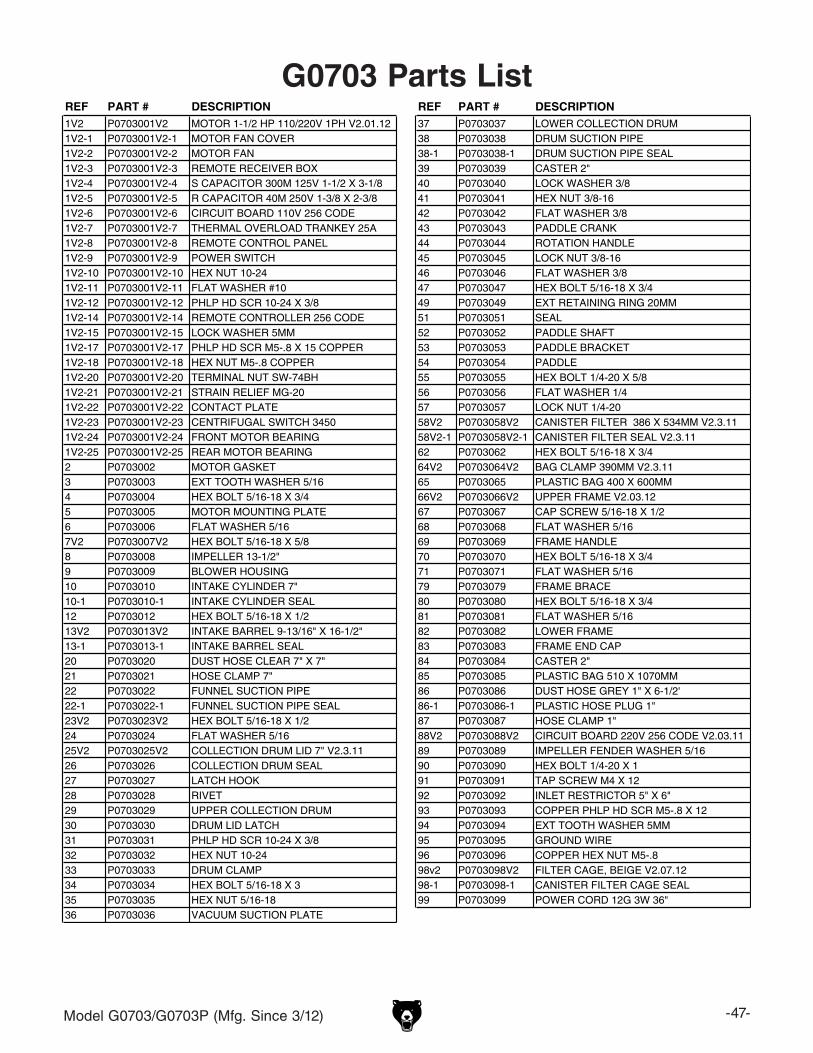
Model G0703/G0703P (Mfg. Since 3/12) -47-
REF PART # DESCRIPTION REF PART # DESCRIPTION1V2 P0703001V2 MOTOR 1-1/2 HP 110/220V 1PH V2.01.12 37 P0703037 LOWER COLLECTION DRUM1V2-1 P0703001V2-1 MOTOR FAN COVER 38 P0703038 DRUM SUCTION PIPE1V2-2 P0703001V2-2 MOTOR FAN 38-1 P0703038-1 DRUM SUCTION PIPE SEAL1V2-3 P0703001V2-3 REMOTE RECEIVER BOX 39 P0703039 CASTER 2"1V2-4 P0703001V2-4 S CAPACITOR 300M 125V 1-1/2 X 3-1/8 40 P0703040 LOCK WASHER 3/81V2-5 P0703001V2-5 R CAPACITOR 40M 250V 1-3/8 X 2-3/8 41 P0703041 HEX NUT 3/8-161V2-6 P0703001V2-6 CIRCUIT BOARD 110V 256 CODE 42 P0703042 FLAT WASHER 3/81V2-7 P0703001V2-7 THERMAL OVERLOAD TRANKEY 25A 43 P0703043 PADDLE CRANK1V2-8 P0703001V2-8 REMOTE CONTROL PANEL 44 P0703044 ROTATION HANDLE1V2-9 P0703001V2-9 POWER SWITCH 45 P0703045 LOCK NUT 3/8-161V2-10 P0703001V2-10 HEX NUT 10-24 46 P0703046 FLAT WASHER 3/81V2-11 P0703001V2-11 FLAT WASHER #10 47 P0703047 HEX BOLT 5/16-18 X 3/41V2-12 P0703001V2-12 PHLP HD SCR 10-24 X 3/8 49 P0703049 EXT RETAINING RING 20MM1V2-14 P0703001V2-14 REMOTE CONTROLLER 256 CODE 51 P0703051 SEAL1V2-15 P0703001V2-15 LOCK WASHER 5MM 52 P0703052 PADDLE SHAFT1V2-17 P0703001V2-17 PHLP HD SCR M5-.8 X 15 COPPER 53 P0703053 PADDLE BRACKET1V2-18 P0703001V2-18 HEX NUT M5-.8 COPPER 54 P0703054 PADDLE1V2-20 P0703001V2-20 TERMINAL NUT SW-74BH 55 P0703055 HEX BOLT 1/4-20 X 5/81V2-21 P0703001V2-21 STRAIN RELIEF MG-20 56 P0703056 FLAT WASHER 1/41V2-22 P0703001V2-22 CONTACT PLATE 57 P0703057 LOCK NUT 1/4-201V2-23 P0703001V2-23 CENTRIFUGAL SWITCH 3450 58V2 P0703058V2 CANISTER FILTER 386 X 534MM V2.3.111V2-24 P0703001V2-24 FRONT MOTOR BEARING 58V2-1 P0703058V2-1 CANISTER FILTER SEAL V2.3.111V2-25 P0703001V2-25 REAR MOTOR BEARING 62 P0703062 HEX BOLT 5/16-18 X 3/42 P0703002 MOTOR GASKET 64V2 P0703064V2 BAG CLAMP 390MM V2.3.113 P0703003 EXT TOOTH WASHER 5/16 65 P0703065 PLASTIC BAG 400 X 600MM4 P0703004 HEX BOLT 5/16-18 X 3/4 66V2 P0703066V2 UPPER FRAME V2.03.125 P0703005 MOTOR MOUNTING PLATE 67 P0703067 CAP SCREW 5/16-18 X 1/26 P0703006 FLAT WASHER 5/16 68 P0703068 FLAT WASHER 5/167V2 P0703007V2 HEX BOLT 5/16-18 X 5/8 69 P0703069 FRAME HANDLE8 P0703008 IMPELLER 13-1/2" 70 P0703070 HEX BOLT 5/16-18 X 3/49 P0703009 BLOWER HOUSING 71 P0703071 FLAT WASHER 5/1610 P0703010 INTAKE CYLINDER 7" 79 P0703079 FRAME BRACE10-1 P0703010-1 INTAKE CYLINDER SEAL 80 P0703080 HEX BOLT 5/16-18 X 3/412 P0703012 HEX BOLT 5/16-18 X 1/2 81 P0703081 FLAT WASHER 5/1613V2 P0703013V2 INTAKE BARREL 9-13/16" X 16-1/2" 82 P0703082 LOWER FRAME13-1 P0703013-1 INTAKE BARREL SEAL 83 P0703083 FRAME END CAP20 P0703020 DUST HOSE CLEAR 7" X 7" 84 P0703084 CASTER 2"21 P0703021 HOSE CLAMP 7" 85 P0703085 PLASTIC BAG 510 X 1070MM22 P0703022 FUNNEL SUCTION PIPE 86 P0703086 DUST HOSE GREY 1" X 6-1/2'22-1 P0703022-1 FUNNEL SUCTION PIPE SEAL 86-1 P0703086-1 PLASTIC HOSE PLUG 1"23V2 P0703023V2 HEX BOLT 5/16-18 X 1/2 87 P0703087 HOSE CLAMP 1"24 P0703024 FLAT WASHER 5/16 88V2 P0703088V2 CIRCUIT BOARD 220V 256 CODE V2.03.1125V2 P0703025V2 COLLECTION DRUM LID 7" V2.3.11 89 P0703089 IMPELLER FENDER WASHER 5/1626 P0703026 COLLECTION DRUM SEAL 90 P0703090 HEX BOLT 1/4-20 X 127 P0703027 LATCH HOOK 91 P0703091 TAP SCREW M4 X 1228 P0703028 RIVET 92 P0703092 INLET RESTRICTOR 5" X 6"29 P0703029 UPPER COLLECTION DRUM 93 P0703093 COPPER PHLP HD SCR M5-.8 X 1230 P0703030 DRUM LID LATCH 94 P0703094 EXT TOOTH WASHER 5MM31 P0703031 PHLP HD SCR 10-24 X 3/8 95 P0703095 GROUND WIRE32 P0703032 HEX NUT 10-24 96 P0703096 COPPER HEX NUT M5-.833 P0703033 DRUM CLAMP 98v2 P0703098V2 FILTER CAGE, BEIGE V2.07.1234 P0703034 HEX BOLT 5/16-18 X 3 98-1 P0703098-1 CANISTER FILTER CAGE SEAL35 P0703035 HEX NUT 5/16-18 99 P0703099 POWER CORD 12G 3W 36"36 P0703036 VACUUM SUCTION PLATE
G0703 Parts List
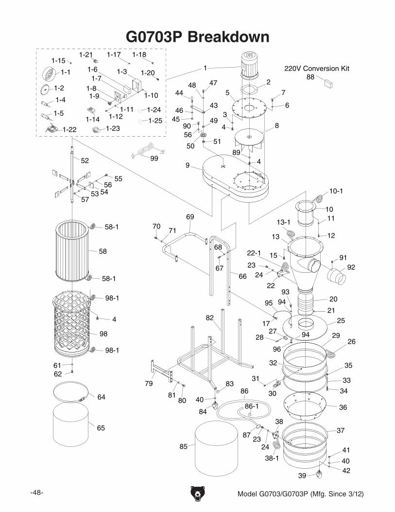
-48- Model G0703/G0703P (Mfg. Since 3/12)
G0703P Breakdown
1
2
3
4
5
6
7
8
9
10
10-1
11
12
13-1
13
15
20
21
22
22-1
25
26
2728 29
30
31
32
33
34
35
36
3738
38-1
39
40
41
42
43
44
4546
4748
49
5051
52
53 54
55
56
57
61
4
98
58-1
58-1
98-1
58
62
64
65
6667
68
6970
71
79
8081
82
83
84
85
86
86-1
87
89
90
9192
939495
96
4
2324
94
17
2423
40
56
220V Conversion Kit88
98-1
1-1
1-2
1-31-61-7
1-81-9 1-10
1-111-12
1-4
1-5
1-211-15
1-22
1-24
1-231-25
1-17
1-20
1-18
1-14
99
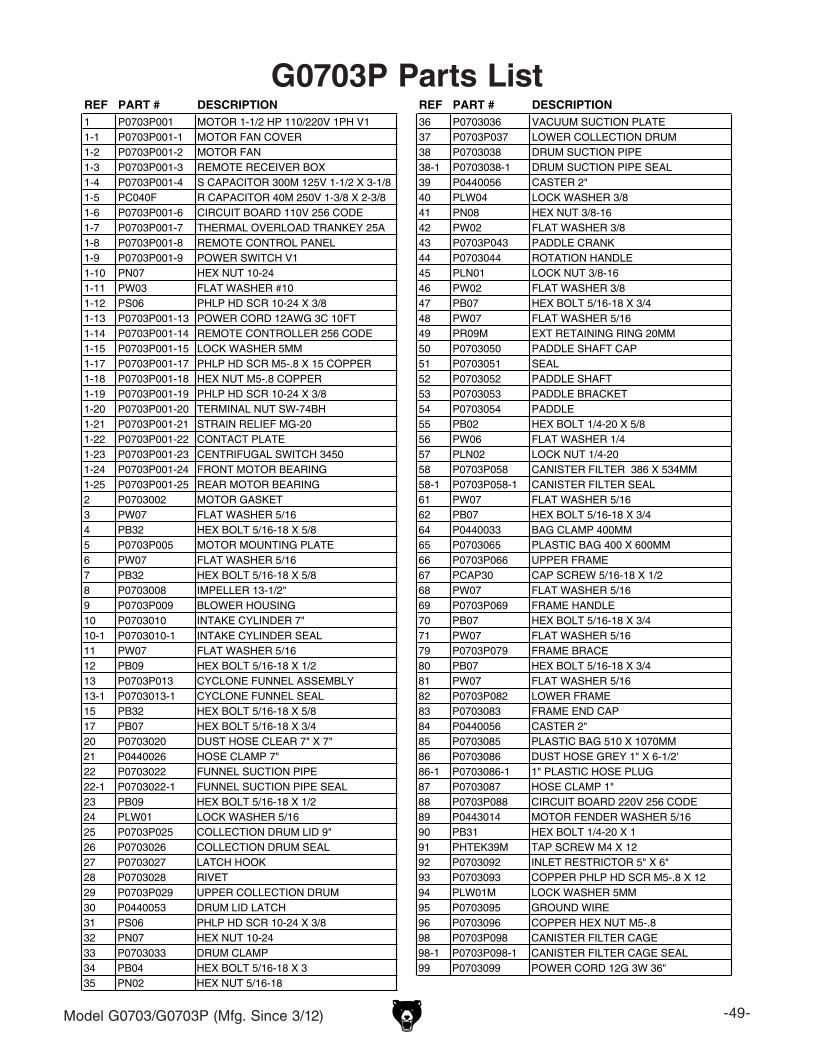
Model G0703/G0703P (Mfg. Since 3/12) -49-
G0703P Parts ListREF PART # DESCRIPTION REF PART # DESCRIPTION1 P0703P001 MOTOR 1-1/2 HP 110/220V 1PH V1 36 P0703036 VACUUM SUCTION PLATE1-1 P0703P001-1 MOTOR FAN COVER 37 P0703P037 LOWER COLLECTION DRUM1-2 P0703P001-2 MOTOR FAN 38 P0703038 DRUM SUCTION PIPE1-3 P0703P001-3 REMOTE RECEIVER BOX 38-1 P0703038-1 DRUM SUCTION PIPE SEAL1-4 P0703P001-4 S CAPACITOR 300M 125V 1-1/2 X 3-1/8 39 P0440056 CASTER 2"1-5 PC040F R CAPACITOR 40M 250V 1-3/8 X 2-3/8 40 PLW04 LOCK WASHER 3/81-6 P0703P001-6 CIRCUIT BOARD 110V 256 CODE 41 PN08 HEX NUT 3/8-161-7 P0703P001-7 THERMAL OVERLOAD TRANKEY 25A 42 PW02 FLAT WASHER 3/81-8 P0703P001-8 REMOTE CONTROL PANEL 43 P0703P043 PADDLE CRANK1-9 P0703P001-9 POWER SWITCH V1 44 P0703044 ROTATION HANDLE1-10 PN07 HEX NUT 10-24 45 PLN01 LOCK NUT 3/8-161-11 PW03 FLAT WASHER #10 46 PW02 FLAT WASHER 3/81-12 PS06 PHLP HD SCR 10-24 X 3/8 47 PB07 HEX BOLT 5/16-18 X 3/41-13 P0703P001-13 POWER CORD 12AWG 3C 10FT 48 PW07 FLAT WASHER 5/161-14 P0703P001-14 REMOTE CONTROLLER 256 CODE 49 PR09M EXT RETAINING RING 20MM1-15 P0703P001-15 LOCK WASHER 5MM 50 P0703050 PADDLE SHAFT CAP1-17 P0703P001-17 PHLP HD SCR M5-.8 X 15 COPPER 51 P0703051 SEAL1-18 P0703P001-18 HEX NUT M5-.8 COPPER 52 P0703052 PADDLE SHAFT1-19 P0703P001-19 PHLP HD SCR 10-24 X 3/8 53 P0703053 PADDLE BRACKET1-20 P0703P001-20 TERMINAL NUT SW-74BH 54 P0703054 PADDLE1-21 P0703P001-21 STRAIN RELIEF MG-20 55 PB02 HEX BOLT 1/4-20 X 5/81-22 P0703P001-22 CONTACT PLATE 56 PW06 FLAT WASHER 1/41-23 P0703P001-23 CENTRIFUGAL SWITCH 3450 57 PLN02 LOCK NUT 1/4-201-24 P0703P001-24 FRONT MOTOR BEARING 58 P0703P058 CANISTER FILTER 386 X 534MM1-25 P0703P001-25 REAR MOTOR BEARING 58-1 P0703P058-1 CANISTER FILTER SEAL2 P0703002 MOTOR GASKET 61 PW07 FLAT WASHER 5/163 PW07 FLAT WASHER 5/16 62 PB07 HEX BOLT 5/16-18 X 3/44 PB32 HEX BOLT 5/16-18 X 5/8 64 P0440033 BAG CLAMP 400MM5 P0703P005 MOTOR MOUNTING PLATE 65 P0703065 PLASTIC BAG 400 X 600MM6 PW07 FLAT WASHER 5/16 66 P0703P066 UPPER FRAME7 PB32 HEX BOLT 5/16-18 X 5/8 67 PCAP30 CAP SCREW 5/16-18 X 1/28 P0703008 IMPELLER 13-1/2" 68 PW07 FLAT WASHER 5/169 P0703P009 BLOWER HOUSING 69 P0703P069 FRAME HANDLE10 P0703010 INTAKE CYLINDER 7" 70 PB07 HEX BOLT 5/16-18 X 3/410-1 P0703010-1 INTAKE CYLINDER SEAL 71 PW07 FLAT WASHER 5/1611 PW07 FLAT WASHER 5/16 79 P0703P079 FRAME BRACE12 PB09 HEX BOLT 5/16-18 X 1/2 80 PB07 HEX BOLT 5/16-18 X 3/413 P0703P013 CYCLONE FUNNEL ASSEMBLY 81 PW07 FLAT WASHER 5/1613-1 P0703013-1 CYCLONE FUNNEL SEAL 82 P0703P082 LOWER FRAME15 PB32 HEX BOLT 5/16-18 X 5/8 83 P0703083 FRAME END CAP17 PB07 HEX BOLT 5/16-18 X 3/4 84 P0440056 CASTER 2"20 P0703020 DUST HOSE CLEAR 7" X 7" 85 P0703085 PLASTIC BAG 510 X 1070MM21 P0440026 HOSE CLAMP 7" 86 P0703086 DUST HOSE GREY 1" X 6-1/2'22 P0703022 FUNNEL SUCTION PIPE 86-1 P0703086-1 1" PLASTIC HOSE PLUG22-1 P0703022-1 FUNNEL SUCTION PIPE SEAL 87 P0703087 HOSE CLAMP 1"23 PB09 HEX BOLT 5/16-18 X 1/2 88 P0703P088 CIRCUIT BOARD 220V 256 CODE24 PLW01 LOCK WASHER 5/16 89 P0443014 MOTOR FENDER WASHER 5/1625 P0703P025 COLLECTION DRUM LID 9" 90 PB31 HEX BOLT 1/4-20 X 126 P0703026 COLLECTION DRUM SEAL 91 PHTEK39M TAP SCREW M4 X 1227 P0703027 LATCH HOOK 92 P0703092 INLET RESTRICTOR 5" X 6"28 P0703028 RIVET 93 P0703093 COPPER PHLP HD SCR M5-.8 X 1229 P0703P029 UPPER COLLECTION DRUM 94 PLW01M LOCK WASHER 5MM30 P0440053 DRUM LID LATCH 95 P0703095 GROUND WIRE31 PS06 PHLP HD SCR 10-24 X 3/8 96 P0703096 COPPER HEX NUT M5-.832 PN07 HEX NUT 10-24 98 P0703P098 CANISTER FILTER CAGE33 P0703033 DRUM CLAMP 98-1 P0703P098-1 CANISTER FILTER CAGE SEAL34 PB04 HEX BOLT 5/16-18 X 3 99 P0703099 POWER CORD 12G 3W 36"35 PN02 HEX NUT 5/16-18
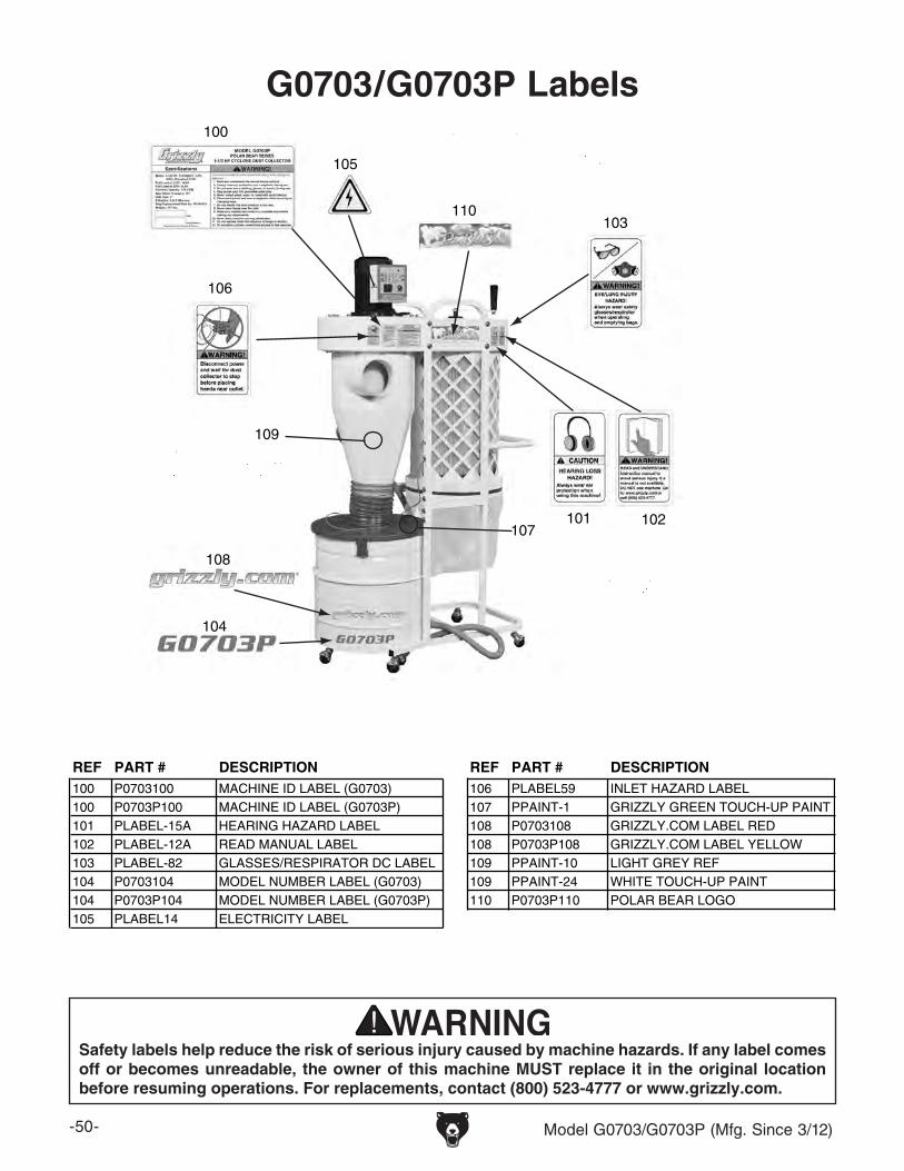
-50- Model G0703/G0703P (Mfg. Since 3/12)
G0703/G0703P Labels
REF PART # DESCRIPTION REF PART # DESCRIPTION100 P0703100 MACHINE ID LABEL (G0703) 106 PLABEL59 INLET HAZARD LABEL100 P0703P100 MACHINE ID LABEL (G0703P) 107 PPAINT-1 GRIZZLY GREEN TOUCH-UP PAINT101 PLABEL-15A HEARING HAZARD LABEL 108 P0703108 GRIZZLY.COM LABEL RED102 PLABEL-12A READ MANUAL LABEL 108 P0703P108 GRIZZLY.COM LABEL YELLOW103 PLABEL-82 GLASSES/RESPIRATOR DC LABEL 109 PPAINT-10 LIGHT GREY REF104 P0703104 MODEL NUMBER LABEL (G0703) 109 PPAINT-24 WHITE TOUCH-UP PAINT104 P0703P104 MODEL NUMBER LABEL (G0703P) 110 P0703P110 POLAR BEAR LOGO105 PLABEL14 ELECTRICITY LABEL
Safety labels help reduce the risk of serious injury caused by machine hazards. If any label comes off or becomes unreadable, the owner of this machine MUST replace it in the original location before resuming operations. For replacements, contact (800) 523-4777 or www.grizzly.com.
100
101
110
102
103
104
106
105
107
109
108

CU
T A
LON
G D
OT
TE
D L
INE
Name _____________________________________________________________________________
Street _____________________________________________________________________________
City _______________________ State _________________________ Zip _____________________
Phone # ____________________ Email _________________________________________________
Model # ____________________ Order # _______________________ Serial # __________________
WARRANTY CARD
The following information is given on a voluntary basis. It will be used for marketing purposes to help us develop better products and services. Of course, all information is strictly confidential.
1. How did you learn about us? ____ Advertisement ____ Friend ____ Catalog ____ Card Deck ____ Website ____ Other:
2. Which of the following magazines do you subscribe to?
3. What is your annual household income? ____ $20,000-$29,000 ____ $30,000-$39,000 ____ $40,000-$49,000 ____ $50,000-$59,000 ____ $60,000-$69,000 ____ $70,000+
4. What is your age group? ____ 20-29 ____ 30-39 ____ 40-49 ____ 50-59 ____ 60-69 ____ 70+
5. How long have you been a woodworker/metalworker? ____ 0-2 Years ____ 2-8 Years ____ 8-20 Years ____20+ Years
6. How many of your machines or tools are Grizzly? ____ 0-2 ____ 3-5 ____ 6-9 ____10+
7. Do you think your machine represents a good value? _____Yes _____No
8. Would you recommend Grizzly Industrial to a friend? _____Yes _____No
9. Would you allow us to use your name as a reference for Grizzly customers in your area? Note: We never use names more than 3 times. _____Yes _____No
10. Comments: _____________________________________________________________________
_________________________________________________________________________________
_________________________________________________________________________________
_________________________________________________________________________________
____ Cabinetmaker & FDM____ Family Handyman____ Hand Loader____ Handy____ Home Shop Machinist____ Journal of Light Cont.____ Live Steam____ Model Airplane News____ Old House Journal____ Popular Mechanics
____ Popular Science____ Popular Woodworking____ Precision Shooter____ Projects in Metal____ RC Modeler____ Rifle____ Shop Notes____ Shotgun News____ Today’s Homeowner____ Wood
____ Wooden Boat____ Woodshop News____ Woodsmith____ Woodwork____ Woodworker West____ Woodworker’s Journal____ Other:

TAPE ALONG EDGES--PLEASE DO NOT STAPLE
FOLD ALONG DOTTED LINE
FOLD ALONG DOTTED LINE
GRIZZLY INDUSTRIAL, INC.P.O. BOX 2069BELLINGHAM, WA 98227-2069
PlaceStampHere
Name_______________________________
Street_______________________________
City______________State______Zip______
Send a Grizzly Catalog to a friend:

WARRANTY & RETURNSGrizzly Industrial, Inc. warrants every product it sells for a period of 1 year to the original purchaser from the date of purchase. This warranty does not apply to defects due directly or indirectly to misuse, abuse, negligence, accidents, repairs or alterations or lack of maintenance. This is Grizzly’s sole written warranty and any and all warranties that may be implied by law, including any merchantability or fitness, for any par-ticular purpose, are hereby limited to the duration of this written warranty. We do not warrant or represent that the merchandise complies with the provisions of any law or acts unless the manufacturer so warrants. In no event shall Grizzly’s liability under this warranty exceed the purchase price paid for the product and any legal actions brought against Grizzly shall be tried in the State of Washington, County of Whatcom.
We shall in no event be liable for death, injuries to persons or property or for incidental, contingent, special, or consequential damages arising from the use of our products.
To take advantage of this warranty, contact us by mail or phone and give us all the details. We will then issue you a “Return Number,’’ which must be clearly posted on the outside as well as the inside of the carton. We will not accept any item back without this number. Proof of purchase must accompany the merchandise.
The manufacturers reserve the right to change specifications at any time because they constantly strive to achieve better quality equipment. We make every effort to ensure that our products meet high quality and durability standards and we hope you never need to use this warranty.
Please feel free to write or call us if you have any questions about the machine or the manual.
Thank you again for your business and continued support. We hope to serve you again soon.