cycleflo ii pneumatic pump controller - graco inc.€¦ · • make sure all electrical work is...
TRANSCRIPT
Instructions/Parts List
CycleFlo II 309004C
ENGPneumatic Pump Controller Controls pump speed for precise batching, metering, and dosing of fluids at high or low pressures and flow rates.
Not for use in explosive atmospheres.
Part No. 195265 120 psi (0.8 MPa, 8 bar) Maximum Air Working Pressure
Integrated Air Valves with Silenced Exhaust
Infinite Cycle Rate Adjustment Between 10 and 200 cpm
Standard 120 VAC Power
Important Safety Instructions Read all warnings and instructions in this manual. Save these instructions.
Table of Contents Warnings . . . . . . . . . . . . . . . . . . . . . . . . . . . . . . . . . . . . . . . . . . . . . . . . . . . . . . . 3 General Description. . . . . . . . . . . . . . . . . . . . . . . . . . . . . . . . . . . . . . . . . . . . . . 5 Installation . . . . . . . . . . . . . . . . . . . . . . . . . . . . . . . . . . . . . . . . . . . . . . . . . . . . . . . 5
Electrical Connections . . . . . . . . . . . . . . . . . . . . . . . . . . . . . . . . . . . . . . . . . . . . 6 Pneumatic Connections. . . . . . . . . . . . . . . . . . . . . . . . . . . . . . . . . . . . . . . . . . . 6
Setup & Adjustment. . . . . . . . . . . . . . . . . . . . . . . . . . . . . . . . . . . . . . . . . . . . . . 8
Cycles Per Minute (CPM) Rate . . . . . . . . . . . . . . . . . . . . . . . . . . . . . . . . . . . . . 8 Adjustment . . . . . . . . . . . . . . . . . . . . . . . . . . . . . . . . . . . . . . . . . . . . . . . . . . . . .
8
Operation. . . . . . . . . . . . . . . . . . . . . . . . . . . . . . . . . . . . . . . . . . . . . . . . . . . . . . 9
Priming the Pump. . . . . . . . . . . . . . . . . . . . . . . . . . . . . . . . . . . . . . . . . . . . . . . . 9 Remote Operation Procedures . . . . . . . . . . . . . . . . . . . . . . . . . . . . . . . . . . . . . 9
Troubleshooting . . . . . . . . . . . . . . . . . . . . . . . . . . . . . . . . . . . . . . . . . . . . . . . . 9 Parts. . . . . . . . . . . . . . . . . . . . . . . . . . . . . . . . . . . . . . . . . . . . . . . . . . . . . . . . . . 10 Typical Installation Diagram. . . . . . . . . . . . . . . . . . . . . . . . . . . . . . . . . . . 11 Technical Data . . . . . . . . . . . . . . . . . . . . . . . . . . . . . . . . . . . . . . . . . . . . . . . . . . 12 Mounting Hole Layout. . . . . . . . . . . . . . . . . . . . . . . . . . . . . . . . . . . . . . . . . . . . 13 Graco Warranty. . . . . . . . . . . . . . . . . . . . . . . . . . . . . . . . . . . . . . . . . . . . . . . . . 14 Graco Phone Number . . . . . . . . . . . . . . . . . . . . . . . . . . . . . . . . . . . . . . . . . . . 14
2 309004
Warning Symbol Caution Symbol
This symbol alerts you to the possibility of serious injury or death if you do not follow the instructions.
This symbol alerts you to the possibility of damage to or destruction of equipment if you do not follow the instructions.
Equipment Misuse Hazard Equipment misuse can cause the equipment to rupture or malfunction and result in serious injury. • This equipment is for professional use only. • Read all instruction manuals, tags, and labels before operating the equipment. • Use the equipment only for its intended purpose. If you are uncertain about usage, call
your Graco distributor. • Other than for installation purposes do not alter or modify this equipment. Use only
genuine Graco parts and accessories. • Check equipment daily. Repair or replace worn or damaged parts immediately. • Do not exceed the maximum working pressure of the lowest rated system component. • Route hoses away from traffic areas, sharp edges, moving parts, and hot surfaces. Do
not expose Graco hoses to temperatures above 200 F (93 C) or below 0 F (-18 C). • Do not lift pressurized equipment. • Comply with all applicable local, state, and national fire, electrical and safety
regulations.
3 309004

Fire, Explosion, and Electric Shock Hazard Improper grounding, poor air ventilation, open flames, or sparks can cause a hazardous condition and resulting fire or explosion and serious injury. • Ground the equipment. • Proper grounding dissipates static electricity generated in the equipment. • This equipment is not intended for intrinsically safe areas. • Keep the dispense area free of debris, including solvent, rags, and gasoline. • If there is any static sparking or you feel an electric shock while using the equipment,
stop operating immediately. Do not use the equipment until you have identified and corrected the problem.
• Make sure all electrical work is performed only by a qualified electrician. • Have any checks, installation or service to electrical equipment performed by a
qualified electrician only. • Make sure all electrical equipment is installed and operated in compliance with local
and applicable codes. • Make sure power is disconnected when servicing and repairing equipment. • Keep liquids away from the electrical components. • Disconnect electrical power at the main switch before servicing the equipment. • Never exceed maximum wattage of the supply unit.
4 309004
General Description The CycleFlo II is a pneumatic pump controller that allows precise control over the cycle rate of the pump and therefor the flow rate. The pump cycle is initiated by a 120 volt signal. The pump cycle may be initiated by some other piece of equipment such as a timer or a pH controller. An isolation relay may be required in some installations. Always follow local and applicable electrical codes. The CycleFlo II will halt the pump cycle whenever the 120 volt signal is removed.
Installation Electrical Connections An access hole with a strain relief installed has been provided for the external power connection. Due to the unique requirements of each installation, access holes have not been provided for the other optional external wiring
connections such as the external air supply valve signal. Have a qualified electrician determine the proper strain relief, wire type, and wire size for your particular application. When positioning or adding access holes, be careful not to damage any internal components. Failure to use the proper strain relief, wire type and wire size can cause damage to internal components or personal injury.
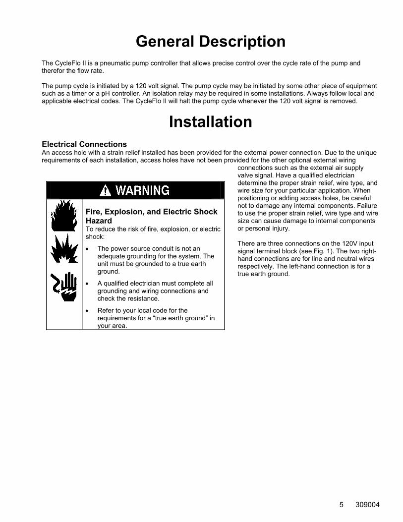
Fire, Explosion, and Electric Shock Hazard To reduce the risk of fire, explosion, or electric shock:
• The power source conduit is not an adequate grounding for the system. The unit must be grounded to a true earth ground.
• A qualified electrician must complete all grounding and wiring connections and check the resistance.
• Refer to your local code for the requirements for a “true earth ground” in your area.
There are three connections on the 120V input signal terminal block (see Fig. 1). The two right-hand connections are for line and neutral wires respectively. The left-hand connection is for a true earth ground.
5 309004
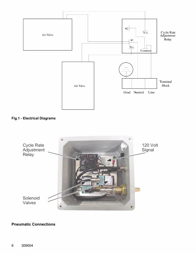
Fig.1 - Electrical Diagrams
Pneumatic Connections
6 309004
Cycle Rate Adjustment Relay
Solenoid Valves
120 Volt Signal
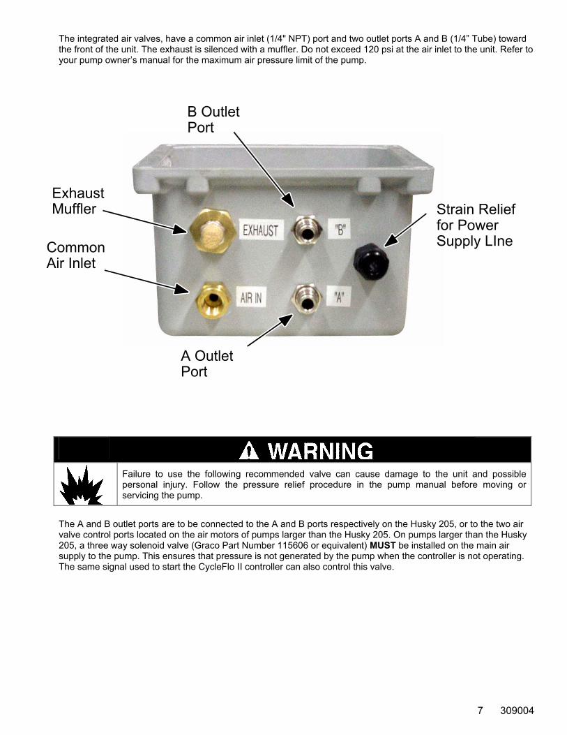
The integrated air valves, have a common air inlet (1/4" NPT) port and two outlet ports A and B (1/4” Tube) toward the front of the unit. The exhaust is silenced with a muffler. Do not exceed 120 psi at the air inlet to the unit. Refer to your pump owner’s manual for the maximum air pressure limit of the pump.
Failure to use the following recommended valve can cause damage to the unit and possible personal injury. Follow the pressure relief procedure in the pump manual before moving or servicing the pump.
The A and B outlet ports are to be connected to the A and B ports respectively on the Husky 205, or to the two air valve control ports located on the air motors of pumps larger than the Husky 205. On pumps larger than the Husky 205, a three way solenoid valve (Graco Part Number 115606 or equivalent) MUST be installed on the main air supply to the pump. This ensures that pressure is not generated by the pump when the controller is not operating. The same signal used to start the CycleFlo II controller can also control this valve.
7 309004
B Outlet Port
Exhaust Muffler
Common Air Inlet
Strain Relief for Power Supply LIne
A Outlet Port
Setup & Adjustment
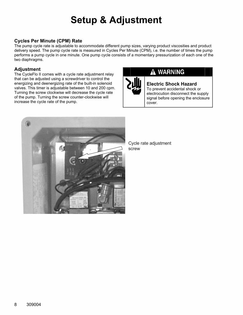
Cycles Per Minute (CPM) Rate The pump cycle rate is adjustable to accommodate different pump sizes, varying product viscosities and product delivery speed. The pump cycle rate is measured in Cycles Per Minute (CPM), i.e. the number of times the pump performs a pump cycle in one minute. One pump cycle consists of a momentary pressurization of each one of the two diaphragms. Adjustment The CycleFlo II comes with a cycle rate adjustment relay that can be adjusted using a screwdriver to control the energizing and deenergizing rate of the built-in solenoid valves. This timer is adjustable between 10 and 200 cpm. Turning the screw clockwise will decrease the cycle rate of the pump. Turning the screw counter-clockwise will increase the cycle rate of the pump.
Cycle rate adjustmentscrew
Electric Shock Hazard To prevent accidental shock or electrocution disconnect the supply signal before opening the enclosure cover.
8 309004
Operation Priming the Pump Prime the pump by applying a 120 Volt signal to the controller to allow the temporary operation of the pump. This cycle rate may be increased or decreased to facilitate pump priming. Shut off electrical supply before making adjustments.
Operation Procedures The controller and pump are now ready for operation. The pump will cycle at the preset rate any time a 120 Volt signal is supplied to the controller.
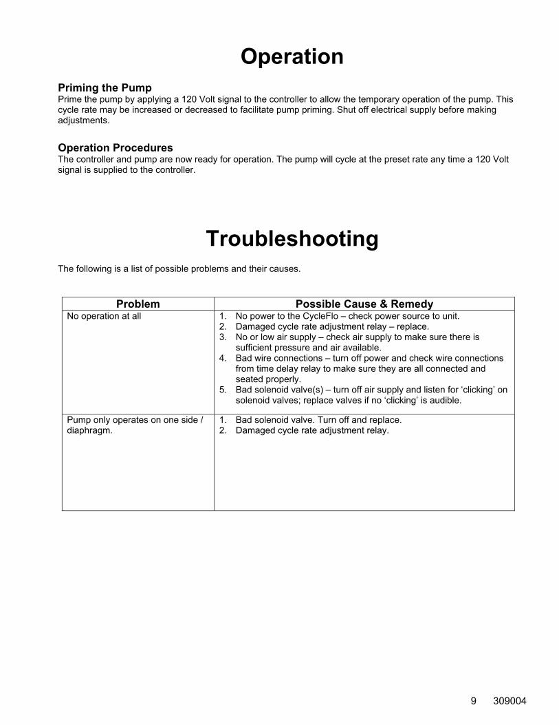
Troubleshooting The following is a list of possible problems and their causes.
Problem Possible Cause & Remedy No operation at all 1. No power to the CycleFlo – check power source to unit.
2. Damaged cycle rate adjustment relay – replace. 3. No or low air supply – check air supply to make sure there is
sufficient pressure and air available. 4. Bad wire connections – turn off power and check wire connections
from time delay relay to make sure they are all connected and seated properly.
5. Bad solenoid valve(s) – turn off air supply and listen for ‘clicking’ on solenoid valves; replace valves if no ‘clicking’ is audible.
Pump only operates on one side / diaphragm.
1. Bad solenoid valve. Turn off and replace. 2. Damaged cycle rate adjustment relay.
9 309004
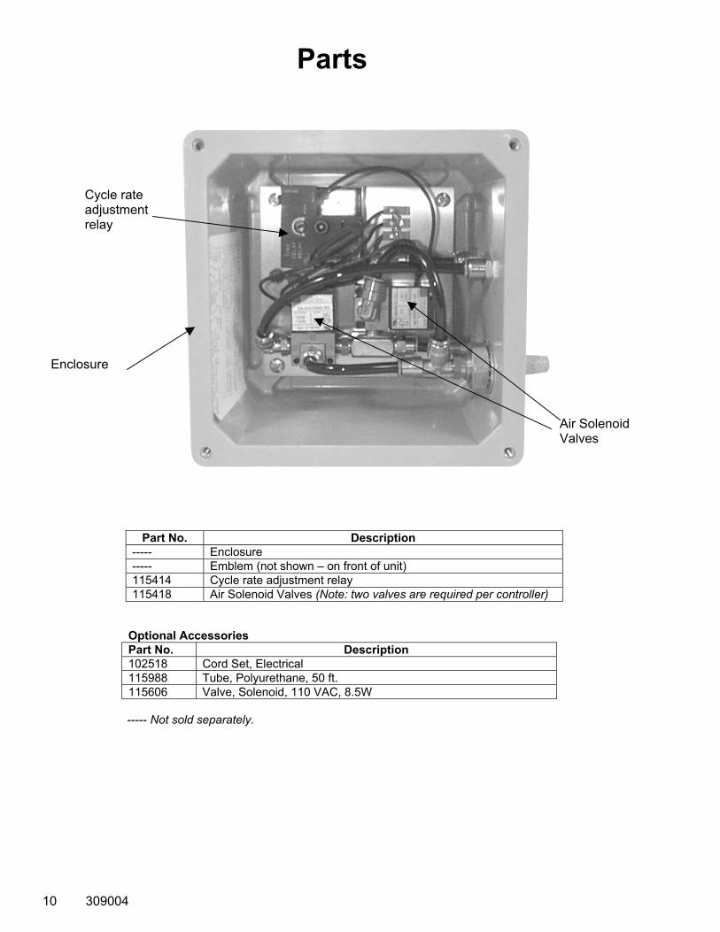
Parts
Cycle rate adjustment relay
Air Solenoid Valves
Enclosure
Part No. Description ----- Enclosure ----- Emblem (not shown – on front of unit) 115414 Cycle rate adjustment relay 115418 Air Solenoid Valves (Note: two valves are required per controller)
Optional Accessories Part No. Description 102518 Cord Set, Electrical 115988 Tube, Polyurethane, 50 ft. 115606 Valve, Solenoid, 110 VAC, 8.5W
----- Not sold separately.
10 309004
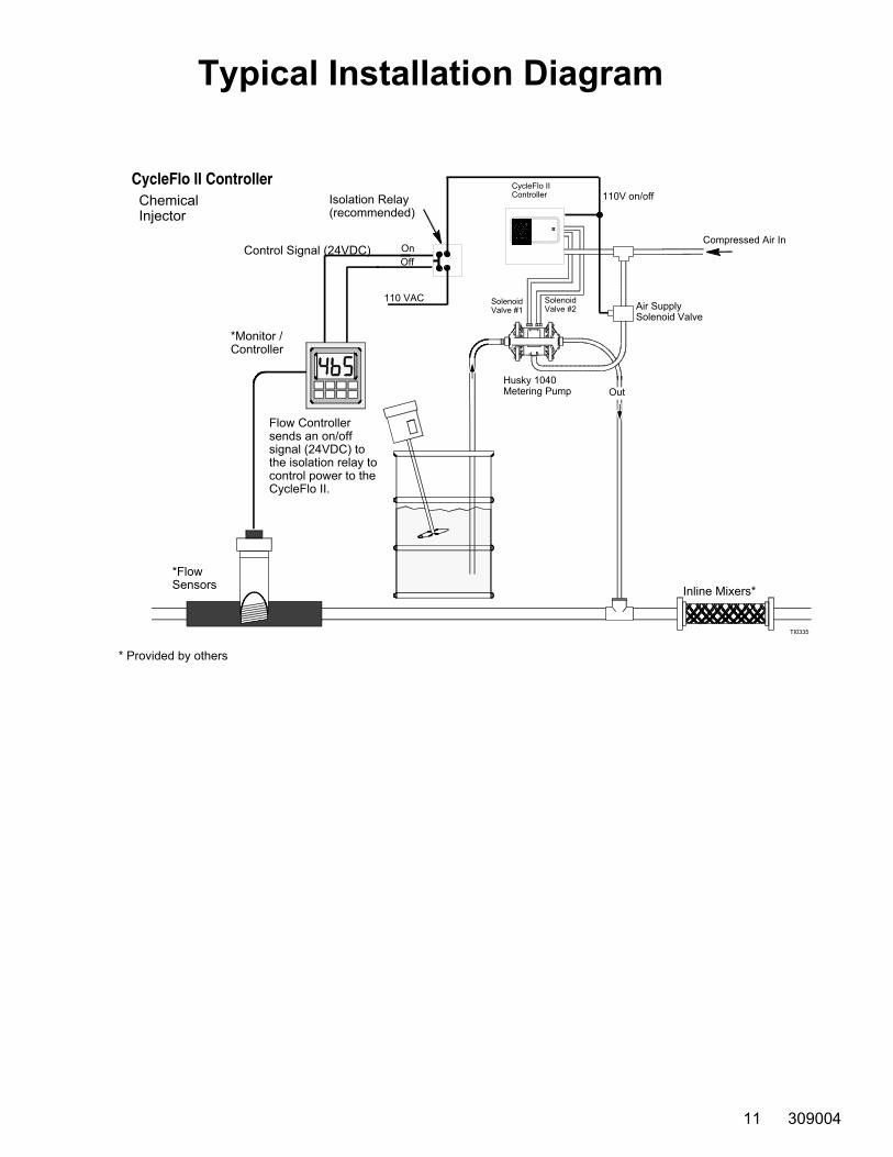
Typical Installation Diagram
*FlowSensors
* Provided by others
*Monitor / Controller
Flow Controller sends an on/offsignal (24VDC) to the isolation relay to control power to the CycleFlo II.
Inline Mixers*
OnOff
Control Signal (24VDC)
110 VAC
Isolation Relay(recommended)
CycleFlo II Controller 110V on/off
SolenoidValve #1
SolenoidValve #2 Air Supply
Solenoid Valve
Out Husky 1040Metering Pump
Compressed Air In
CycleFlo II ControllerChemicalInjector
TI0335
11 309004
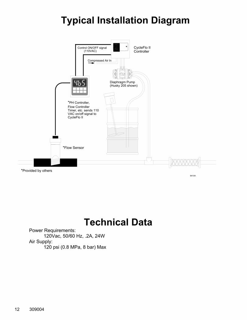
Typical Installation Diagram
9410A
CycleFlo IIController
Compressed Air In
Diaphragm Pump(Husky 205 shown)
*PH Controller,Flow ControllerTimer, etc. sends 110 VAC on/off signal to CycleFlo II
Control ON/OFF signal (110VAC)
*Flow Sensor
*Provided by others
Technical Data Power Requirements: 120Vac, 50/60 Hz, .2A, 24W Air Supply: 120 psi (0.8 MPa, 8 bar) Max
12 309004
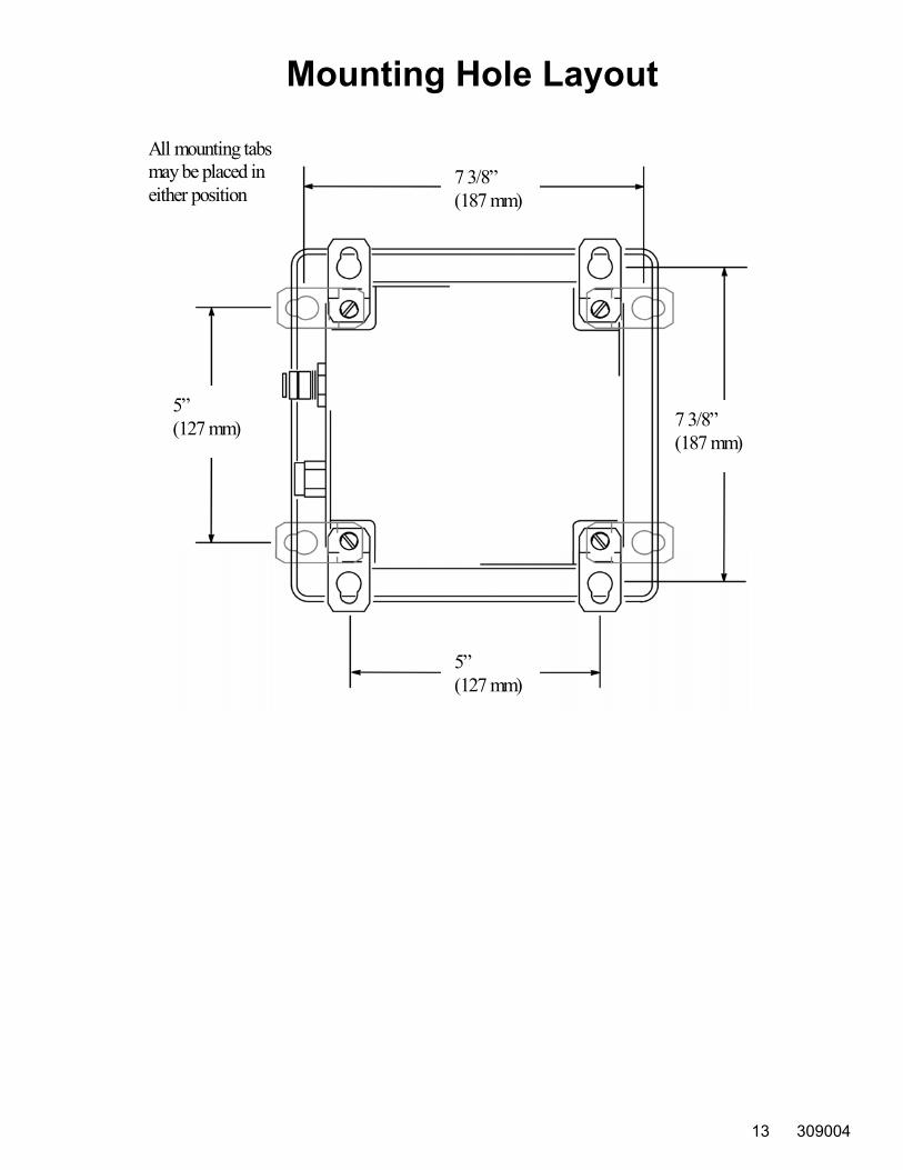
Mounting Hole Layout
All mounting tabsmay be placed ineither position
7 3/8”(187 mm)
5”(127 mm) 7 3/8”
(187 mm)
5”(127 mm)
13 309004

Graco Standard Warranty Graco warrants all equipment referenced in this document which is manufactured by Graco and bearing its name to be free from defects in material and workmanship on the date of sale by an authorized Graco distributor to the original purchaser for use. With the exception of any special, extended, or limited warranty published by Graco, Graco will, for a period of twelve months from the date of sale, repair or replace any part of the equipment determined by Graco to be defective. This warranty applies only when the equipment is installed, operated and maintained in accordance with Graco's written recommendations. This warranty does not cover, and Graco shall not be liable for general wear and tear, or any malfunction, damage or wear caused by faulty installation, misapplication, abrasion, corrosion, inadequate or improper maintenance, negligence, accident, tampering, or substitution of non-Graco component parts. Nor shall Graco be liable for malfunction, damage or wear caused by the incompatibility of Graco equipment with structures, accessories, equipment or materials not supplied by Graco, or the improper design, manufacture, installation, operation or maintenance of structures, accessories, equipment or materials not supplied by Graco. This warranty is conditioned upon the prepaid return of the equipment claimed to be defective to an authorized Graco distributor for verification of the claimed defect. If the claimed defect is verified, Graco will repair or replace free of charge any defective parts. The equipment will be returned to the original purchaser transportation prepaid. If inspection of the equipment does not disclose any defect in material or workmanship, repairs will be made at a reasonable charge, which charges may include the costs of parts, labor, and transportation. THIS WARRANTY IS EXCLUSIVE, AND IS IN LIEU OF ANY OTHER WARRANTIES, EXPRESS OR IMPLIED, INCLUDING BUT NOT LIMITED TO WARRANTY OF MERCHANTABILITY OR WARRANTY OF FITNESS FOR A PARTICULAR PURPOSE. Graco's sole obligation and buyer's sole remedy for any breach of warranty shall be as set forth above. The buyer agrees that no other remedy (including, but not limited to, incidental or consequential damages for lost profits, lost sales, injury to personal property, or any other incidental or consequential loss) shall be available. Any action for breach of warranty must be brought within two (2) years of the date of sale. GRACO Makes no warranty and disclaims all implied warranties of merchantability and fitness for a particular purpose in connection with accessories, equipment, materials or components sold but not manufactured by GRACO. These items sold, but not manufactured by Graco (such as electric motors, switches, hose, etc.), are subject to the warranty, if any, of their manufacturer. Graco will provide purchaser with reasonable assistance in making any claim for breach of these warranties. In no event will Graco be liable for indirect, incidental, special or consequential damages resulting from Graco supplying equipment hereunder, or the furnishing, performance, or use of any products or other goods sold hereto, whether due to a breach of contract, breach of warranty, the negligence of Graco, or otherwise. FOR GRACO CANADA CUSTOMERS The parties acknowledge that they have required that the present document, as well as all documents, notices and legal proceedings entered into, given or instituted pursuant hereto or relating directly or indirectly hereto, be drawn up in English. Les parties reconnaissent avoir convenu que la rédaction du présent document ainsi que de tous les documents, avis et procédures judiciaires exécutés, donnés ou intentés à la suite de ou en rapport, directement ou indirectement, avec les procédures concernées sera en Anglais.
Graco Phone Number
For the latest information about Graco products, visit www.graco.com. TO PLACE AN ORDER, contact your Graco distributor, or call this number to identify the distributor closest to you: Phone: 612-623-6921 or Toll Free: 1-800-328-0211 Fax: 612-378-3505
All written and visual data contained in this document reflects the latest product information available at the time of publication. Graco reserves the right to make changes at any time without notice.
This manual contains English. MM 309004
Graco Headquarters: Minneapolis International Offices: Belgium, China, Japan, Korea
GRACO INC. P.O. BOX 1441 MINNEAPOLIS, MN 55440-1441
Copyright 1999, Graco Inc. is registered to ISO 9001 www.graco.com Revised 09/2009
14 309004