cycle car with moto wheel
TRANSCRIPT

1920 Briggs & Stratton Cycle Car
with
Motor Wheel Drive
Copyright 2006Everett Moore
Everett MooreP.O. Box 1705
Cottonwood, AZ 86326
1

I originally built the Briggs and StrattonCycle Car without the conventional motorwheel drive. This was done to create an sim-ple, easy to build car for the beginningbuilder. It required no welding or machinework other than simply cutting a few piecesof steel to length.
This little car functioned fine, but was notwithout the peculiarities of one-wheel drive. Iwas not totally satisfied and became inspiredto build a motor-wheel to power it.
Rather than build another Cycle Car fromscratch, I decided to alter the existing one toaccept the motor-wheel. I kept in mind thatmany of you have built from the originaldesign and I wanted to make it as easy aspossible to alter yours to accept the motor-wheel.
Some further modifications were madeincluding changing from a hand brake leverto a conventional, foot operated, brake. Withthe exception of moving the equalizer assem-bly, all the original brake parts were used. Idid re-design the brake band anchor bracketsto provide a better geometry for clamping thebrake band, resulting in an improvement instopping power.
The motor-wheel is a self-contained unitthat attaches to the chassis board with 2brackets that allow it to pivot up and down,thereby maintaining constant contact withthe road. The only other attachment to car isthe throttle cable. This cable terminates cen-trally below the front edge of the seat and iscontrolled by hand. We chose to simplify thedesign on the motor-wheel and only used acentrifugal clutch.
The motor-wheel was designed with theidea that the builder could adapt it to aboutanything, similar to what was done with the
original Smith Motor-Wheel. Since a cen-trifugal clutch was used, it eliminated thenecessity for a lever, linkage, etc. to lift themotor-wheel off the road for starting.
A Worksman wheel and Kevlar tire wasused on the motor-wheel. Power was provid-ed to the wheel by using a 15 inch, “V” beltsheave as used on a Whizzer Motor Bike.These sheaves and mounting brackets areavailable from Whizzer dealers or directlyfrom Whizzer.
The most difficult task in building themotor-wheel is getting the belt sheavemounted concentrically on the wheel. Sometrial and error may be necessary.
Upon completion, some adjustment wasnecessary to the jack shaft to get the propertension on the “V” belt. We managed to get bywithout using a spring-loaded idler pulley tokeep the belt tight, although that could be anoption.
The entire car was completed in time for ashake-down cruise in the Cottonwood, AZChristmas Parade. It performed flawlesslyand finished the parade with it’s two passen-gers plus dog!
These plans were done with three possibleend results in mind.
1) Modifying an existing Cycle Car builtfrom our original plans.
2) Building a completely new Cycle Car fromthe beginning.
3) Build only the motor/wheel unit for adapt-ing to a personal project.
Enjoy and email me if you have any ques-tions. [email protected]
2
Foreword

"Tattoo the above quotes on your brain" asErnest used to say. Better yet, paint them assigns to hang in your shop where you can lookat them every time the going gets rough.
It was with this incentive that the manu-al you're holding was done. With its nearly200 different parts not even a simple cyclecar is necessarily easy. However, ifapproached one part at a time, the jobbecomes much easier.
Sometimes when you buy a set of plans fora project such as this, all you get is a copy ofa magazine article or everything crowdedonto a few sheets of paper.
In this manual you will find a completedrawing of each part — nothing is left for you— no guess work! A lot of parts are simply apiece of bar stock, angle or tubing cut tolength with one or more holes drilled in it.
This is not to imply that you can't go offthe beaten trail and modify or redesign toyour own desires. To do so is encouraged.
The idea that this horseless carriage couldbe approached as a class project crossed ourmind. Since it utilizes several machine shopoperations, each student could be assigned afew parts to do according to their ability andskills. When completed, let the auto body
shop do the painting. Then drive in the home-coming parade! The Industrial Arts Deptwins, hands down!
The same could apply to friends or neigh-bors who join together to build each a carwith different ones making all of certainparts.
A few tools I consider a necessity (eitherowning or having access to) and they are: acut-off saw, a drill press, a hand grinder, anaccurate square (combination & large carpen-ter's square), a bottle of layout blue and themeans of accurately-scribing layout lines onthe stock. Always center punch all holesbefore drilling.
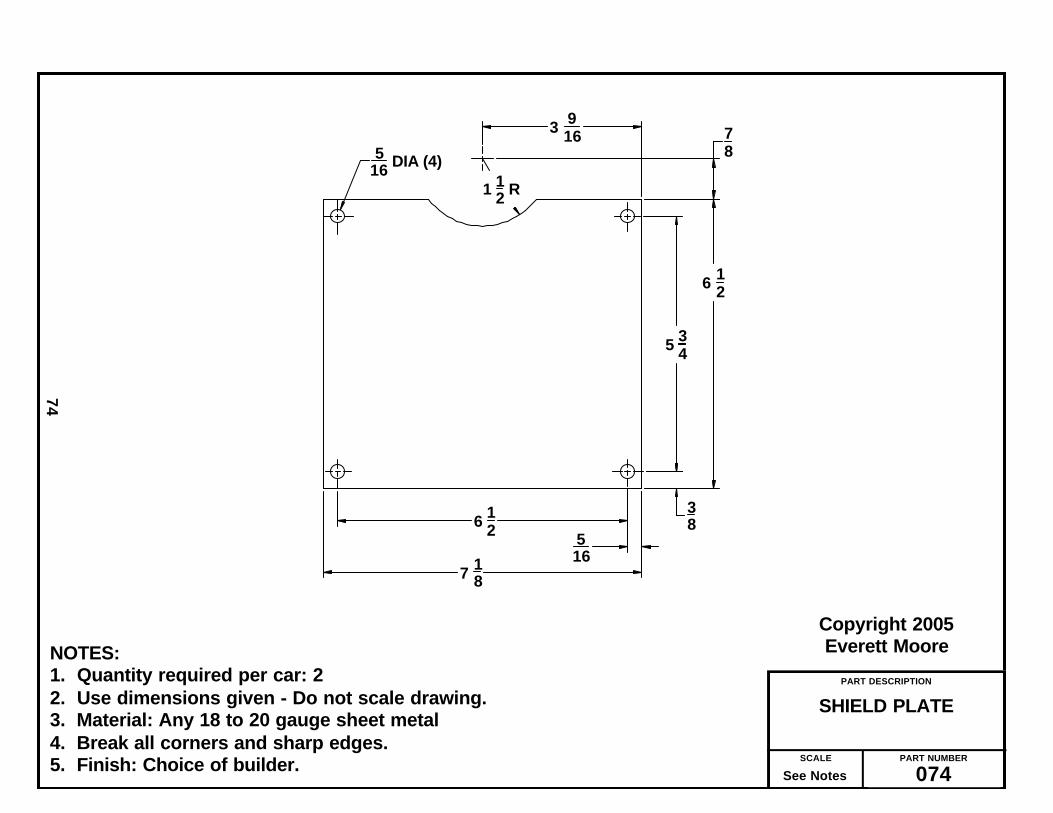
The motor-wheel unit does require somebasic welding on the frame. The jack shaftmount was build from individual parts boltedtogether (Erector Set style). Note that shieldplates were used for safety on this unit.
Before you start making scrap iron, studythis manual and drawings. Obtain catalogsfrom suppliers and if you have access to theinternet, look at and bookmark the supplierswe have referenced.
Plan where you are going to work on yourcar. Although desirable, a large shop isn'tnecessary. Henry Ford utilized a coal shed for
3
Introduction
“Nothing is particularly hardif you divide it into small jobs.”
— Henry Ford
“Before everything else,getting ready is the secret of success.”
— Henry Ford

his first horseless carriage, the Quadricycle.And, while Henry said “plan ahead,” he evenhad to knock out the existing door and add alarger one just to get his car outside!
Visit your local steel supplier. Dependingon your location, you may have access to awell-stocked supplier. If you live in a ruralarea, look for a welding shop that might havesome scrap or be willing to order for you.
— What Tools Will You Need? —
Tools, while making any job easier, cannotreplace skill in the hands using them. Thelist of tools that follows are what I considersufficient to build the “Red Bug.”
1. A good floor-standing drill press. Includes a drill press vice and drill bitset.
2. A quality table saw.3. A good metal chop saw.4. An electric hand drill (3/8)5. A bellhangers drill bit (1/4)6. A set of Forstner drills.7. A hand jig saw.8. A drum sander (either individual or
attachment for drill press.9. A hand, belt sander is very useful.
10. A bench grinder or hand grinder for smoothing metal parts.
11. A good tap and die set (both NC & NF)12. A box of Band Aids!13. Arc welder — or have welding done.
— Start with the wooden parts —
It is only a suggestion that you start withthe wooden parts. The chassis is not unlikethe foundation when building a house. Sincemost other components rely on it for align-ment, care must be exercised when laying outthe various locations on the chassis.
Set the frame on a couple of saw horses.Every time you enter your shop you will seeit and it will trigger your mind to the ideathat, "By golly I'm really building a car - fromscratch - by myself". "I wonder when the nextparade in town is." Also, since the chassis isbasically a 2 x 8 ft piece of 3/4 plywood, itmakes an excellent place to sit down andmake other small parts. Seeing you car takeshape is a thrill you'll never forget.
On the original Briggs & Stratton CycleCar, the chassis was constructed from six 31/2” wide boards of (I would guess) 1” thickoak or hickory. If you have such available, goahead and substitute for the plywood I used.
I used a 2 x 8 sheet of 3/4 plywood andadded “phony” slats by gluing 3 1/2 widestrips of 1/4 plywood to the top surface. Ifound this arrangement to be a bit “flexible”with a payload of 450 lbs. Therefore, a sup-port, made from a 2x4, was added to each onthe underside.
_______________
4
The Original 1920 Briggs and Stratton Cycle Car

5
The Finished Cycle CarFeaturing the Motor Wheel

Let’s Make Sawdust First
I would recommend that all the woodenparts be sawed out at the same time. Thiswill reduce the large sheets of plywood into,smaller, more manageable pieces. In some ofthe next pages you will find rough, cutoutdimensions.
Rip all similar width pieces at the samesaw setting. Start with the widest and pro-ceed to the smaller ones.
You might consider finishing the seat,cushion bases and seat support first and setthem aside for final painting.
You will note how the axles are made bygluing pieces of 3/4 inch plywood together toget the desired thickness. The front axle isstraight forward gluing together of 3 identi-cal pieces. Whether you cut the profile of thefront axle in the individual pieces or aftergluing, is up to you.
Note how the rear axle has a dado (1 x 1)to hold the 1” square axle tube at assembly.You can come close to this dado by sawing thefiller pieces as shown. However, because ofthe varying thickness of purchased plywood,you will most likely have to “fine tune” thedado for a good fit to the steel tube. This fitshould be close enough to allow epoxying thetube at final assembly. The tube must beflush to top surface of axle after assembly.
The foot rest is, likewise, made by gluingtogether two pieces of 3/4 inch plywood.
The fun piece is the steering shaft supportwhich, because of its shape, I call the “dogbone.” Like the front axle, you might want tosaw the 2 individual pieces before gluingtogether. A good drum sander is very usefulin the finishing of this part. Save the drillinguntil after the gluing is done.
While I didn’t specify any corner round-ing, I personally used a hand router and a1/4” round over bit to make a lot of edges“look pretty.”
I, also, spared a lot of little detail on the
wood parts because I find most people withany degree of a home workshop will usuallyhave sufficient woodworking skills to suffice.
I recommend that any finished wood partbe left without paint at this time. You shouldcompletely finish, assemble and test driveyour car and only then disassemble andpaint.
_______________
6
The Making and Assembly Processes
A city version of the Cycle Car was madelater, using electric power for use in large
estates as personal transportation.It was call the “Red Bug.” We named ours
Red Bug, likewise.

PART DESCRIPTION
SHEET - 1PLYWOOD CUTTING
PART NUMBER
007SCALE
See Notes
Copyright 2006Everett Moore
7
NOTES:1. Quantity required per car: 12. Use dimensions given - Do not scale drawing.3. Material: 3/4 Plywood - full 4 x 8 sheet.4. Saw cuts have been allowed for.
40 14
1534
front axle front axle front axle
rear axle rear axle
CHASSIS
seat support front
foot rest
foot rest
rear axle
seat support front
seat supportside
seat supportside
24
3
5 14
24 22 12 15 34 15 34
22 12
31 3/4 31 3/4 31 3/4 4 14
3 12
38 3
2 12
3 34
48
seat support botton
86
96

PART DESCRIPTION
SHEET - 2PLYWOOD CUTTING
PART NUMBER
008SCALE
See Notes
Copyright 2004Everett Moore
8
NOTES:1. Quantity required per car: 12. Use dimensions given - Do not scale drawing.3. Material: 1/4 Plywood - full sheet
3 12 ( X6 )
2 12
floor slat x 6
floor slat x 6
floor slat x 6
floor slat x 6
floor slat x 6
floor slat x 6

PART DESCRIPTION
SHEET - 3, SEATPLYWOOD CUTTING
PART NUMBER
009SCALE
See Notes
Copyright 2004Everett Moore
9
NOTES:1. Quantity required per car: 12. Use dimensions given - Do not scale drawing.3. Material: 3/4 Plywood
17.00
16.00
8.00
1.75
44.00
17.00 17.00
40.00
Back
Side Side
Bottom
Seat Back Strip
48.00
48.00

PART DESCRIPTION
TOP VIEWCHASSIS —
PART NUMBER
010SCALE
See Notes
Copyright 2005Everett Moore
010
NOTES:1. Quantity required per car: 12. Use dimensions given - Do not scale drawing.3. Material: 3/4” Plywood — Imitation Slats = 1/4” Plywood.4. All hole dia’s to be 3/8” except those marked “x” which are 1/4”.5. Some hole dia’s are called out on hole patterns.6. See text for more drilling instructions.7. Break all corners and sharp edges.8. Finish: Choice of builder.
8
15 12
20 27
48 12
72
4 14 7 78
2
2 116
2 116
18 R
10 516
10 516
6 58
1 14
Center Line Rear Axle
Center Line Front Axle
10 (ref) 1
1Hole Pattern "A"
4 R
Hole Pattern "B"
xx
x x
xx
xx
Center Line of Chassis
2
20 3 Center on groove
*
*
*
*
Dims marked with ( * ) apply to both front and rear axle mounting holes.
Hole Pattern "D"
42.00
4
1 12 R
86
x
x
4

PART DESCRIPTION
SHEET 2CHASSIS - TOP VIEW
PART NUMBER
011SCALE
See Notes
Copyright 2005 - Everett Moore
011
HOLE PATTERN LAYOUTSUse dimensions given - Do not scale drawing.
38 DIA - 2 Holes
3
1 12
38 R
3 12
38 DIA - 2 Holes
1 383
2 12
5 1238 R
14 DIA - 2 Holes
1 12
Cut relief to clear 1/4" flat washer Cut thru 1/4" imitation slat - 2 places
A B
DHole patterns “C” & “E” are not used.

PART DESCRIPTION
PIVOT SHAFTMOTOR WHEEL
PART NUMBER
012SCALE
See Notes
Copyright 2005Everett Moore
12
NOTES:1. Quantity required per car: 12. Use dimensions given - Do not scale drawing.3. Material: .750 dia CRS.4. Break all corners and sharp edges.5. Finish: Choice of builder.
10 3812
12
18 DIA (2)
18 R .750 dia CRS

PART DESCRIPTION
FOOT REST
PART NUMBER
013SCALE
See Notes
Copyright 2004Everett Moore
013
NOTES:1. Quantity required per car: 12. Use dimensions given - Do not scale drawing.3. Material: 3/4 Plywood. Glue 2 pieces together.4. Break all corners and sharp edges.5. Finish: Choice of builder.
6
38 DIA - 2 Holes
36
1 12
1 R
3 R1 12
6
1
1 12
7 34
3
20 12
3 R

PART DESCRIPTION
SUB - ASSEMBLYFRONT AXLE
PART NUMBER
014SCALE
See Notes
Copyright 2004Everett Moore
014
NOTES:1. Quantity required per car: 12. Use dimensions given - Do not scale drawing.3. Material: 3/4 Plywood (3 pieces glued together)4. Break all corners and sharp edges.5. Finish: Choice of builder.
2 12
4 14
2 1478
1 18
Center Line of Chassis
10 516
2 116 2 1
16
10 516
2 14 78
38 DIA - 8 holes 2 14 (ref)
3 1316 both ends
13 1316 both ends
31 342 34 - 4 plcs
1" Dia. C'bore to depth shown - Typical 4 Places

PART DESCRIPTION
ASSEMBLYREAR AXLE
PART NUMBER
015SCALE
See Notes
Copyright 2004Everett Moore
015
NOTES:1. Quantity required per car: 12. Use dimensions given - Do not scale drawing.3. Material: 3/4 plywood (3 pieces), 1/4” plywood (1 piece) Cut to dims shown.
1” square x .120 wall steel tubing - 34.750 long4. Glue plywood pieces together as shown. When dry, epoxy steel tube in
to dimensions shown. Tube and plywood to be flush at top.5. Plywood thickness can vary. Therefore it may be necessary to touch up the
1” dado on the table saw to make a snug but loose fit between steel and wooden axle.
6. Break all corners and sharp edges.7. Finish: Choice of builder.
1 14 1 14 Center line
10 516
2 116 2 1
16
10 516
34 34
1 12
1 12 38 DIA - 4 holes
14 DIA - 12 holes
2 122 12
3 12
1 916 (ref - both ends)31 34
1 14 - Typical 6 places
Sq tube & plywood surfaces to be flush this entire surface34 78
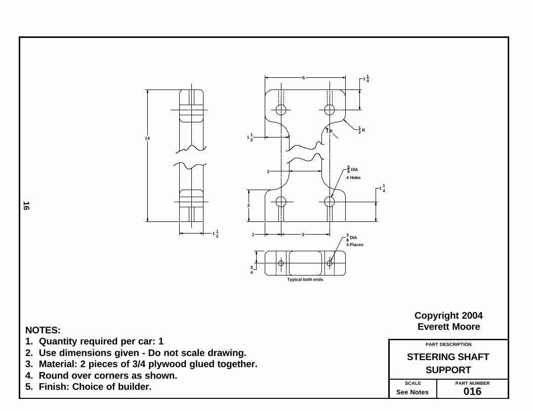
PART DESCRIPTION
SUPPORTSTEERING SHAFT
PART NUMBER
016SCALE
See Notes
Copyright 2004Everett Moore
16
NOTES:1. Quantity required per car: 12. Use dimensions given - Do not scale drawing.3. Material: 2 pieces of 3/4 plywood glued together.4. Round over corners as shown.5. Finish: Choice of builder.
1 14
2
11 12
58 DIA
3
4 Places
34
Typical both ends
4 Holes
1 R12 R
1 12
2
5
14
1 14
38 DIA

PART DESCRIPTION
ASSEMBLYSEAT SUPPORT
PART NUMBER
017SCALE
See Notes
Copyright 2004Everett Moore
17
NOTES:1. Quantity required per car: 12. Use dimensions given - Do not scale drawing.3. Material: 3/4” Plywood.4. Glue & screw together.5. Finish: Choice of builder.
15 34
22 12
24
7 78
20
2 2 (REF)
38 DIA - 2 Holes
3 34
6
5 14
4 12

PART DESCRIPTION
SEAT ASSEMBLY
PART NUMBER
018SCALE
See Notes
Copyright 2004Everett Moore
18
NOTES:
1. Use dimensions shown. Do not scale drawing.2. Material: 3/4 in. plywood.3. Referring to this drawing and drawing XXX, cut two slots to accept corner brackets.4. Fit parts - glue - reinforce with screws and corner brackets.
15 34
40
4 R
4 R
80°
44
15
16
1 14
2
17
15
16 516
Front corner top viewTypical two places
3 12
o
1 R
8

PART DESCRIPTION
SEAT - REAR DETAIL
PART NUMBER
019SCALE
See Notes
Copyright 2004Everett Moore
19
NOTES:
1. Cut two slots as shown. Use router preferably. However, multiple holes can bedrilled and connected with jig saw. Slot should only be wide enough to acceptthe bracket. Prototype used 1/4 in.
2. Drill 1/4 dia holes thru seat back & arm rests and secure brackets with 1/4 - 20bolts, fender washers and nuts. Place nuts on outside.
Cut slot thru seat back to accept corner bracketboth sides
4 in corner reinforcing bracketfasten to rear of seat, extend thru slotfasten to outside of arm rest. ( 2 places )
Rear view of seat
Detail of seat back reinforcement
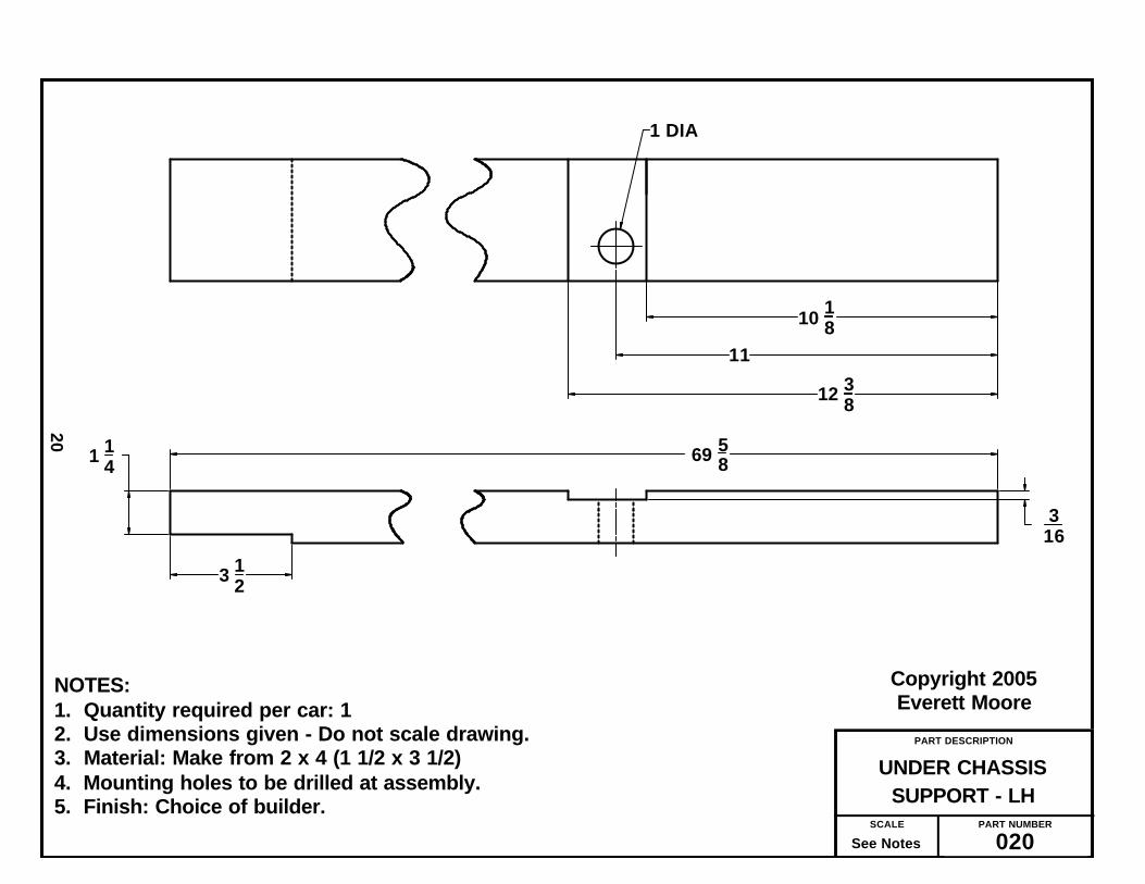
PART DESCRIPTION
SUPPORT - LHUNDER CHASSIS
PART NUMBER
020SCALE
See Notes
Copyright 2005Everett Moore
20
NOTES:1. Quantity required per car: 12. Use dimensions given - Do not scale drawing.3. Material: Make from 2 x 4 (1 1/2 x 3 1/2)4. Mounting holes to be drilled at assembly.5. Finish: Choice of builder.
10 1811
12 38
3 12
1 14 69 58
316
1 DIA

PART DESCRIPTION
SUPPORT - RHUNDER CHASSIS
PART NUMBER
021SCALE
See Notes
Copyright 2005Everett Moore
21
NOTES:1. Quantity required per car: 12. Use dimensions given - Do not scale drawing.3. Material: Make from 2 x 4 (1 1/2 x 3 1/2)4. Mounting holes to be drilled at assembly.5. Finish: Choice of builder.
1
10 1811
12 38
69 58
316
1 DIA

If you haven’t already, you might want tocut the 1” square tube to required length andfinish the rear axle per drawing No. 015.
Be sure to align your chop saw so as to cutas near to 90 degrees as possible. I nevertrust the marks provided and prefer to use asquare to do this.
I recommend cutting all bar stock, anglesand motor-wheel parts to the required lengthat one time. Next, remove any burrs andsharp edges with a hand file.
To layout the hole locations, you shouldhave a small bottle of layout blue. You needonly apply it to the approximate area wherethe holes will be. Accurately locate the holeswith a good square and scale. Scribe lineswith a scriber and center punch beforedrilling holes.
When all holes are drilled, using either abench grinder or hand grinder, form theradius’ called out on the drawings. These arenot critical and in some cases are more forappearance than anything else.
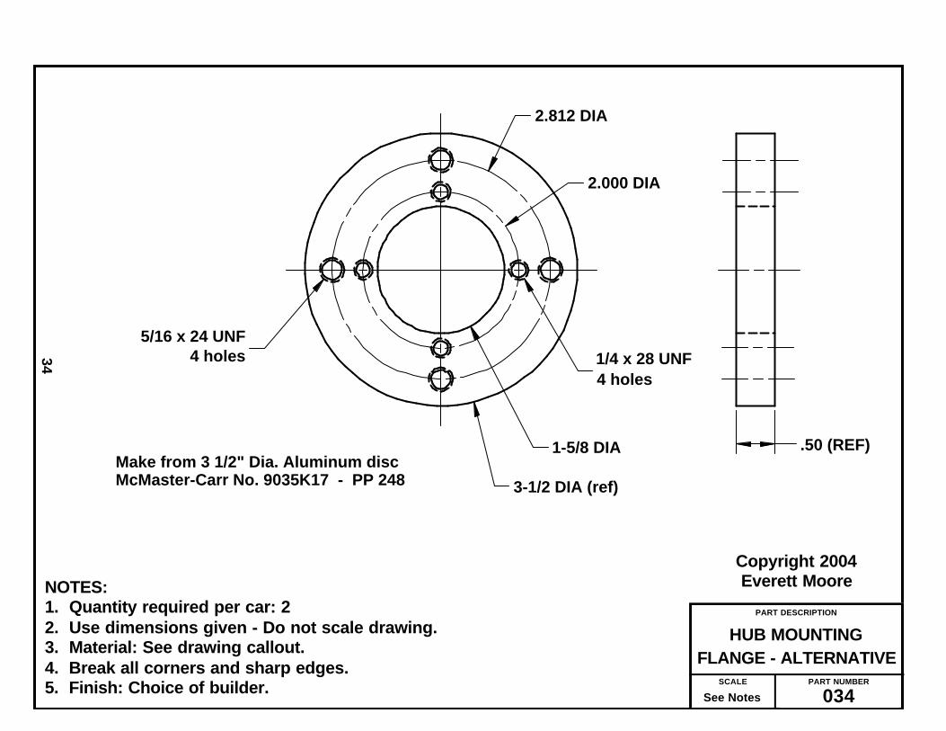
One of the more difficult parts will be thetwo hub mounting flanges, Drawing No. 034.Layout and scribe the hole locations withyour square and compass or use the card-board tool described in Drawing No. 035.
Using the appropriate tap drill, drill andthen tap holes per drawing. If you have neverused a tap before, do two things — 1) Use acutting fluid to lubricate the tap while cut -ting (I use WD-40) 2) Every couple or threeturns of the tap, stop and backup a turn tobreak the chip and free the tap again.
Don’t force the tap, back up, and go again.Nothing will make a grown man cry quickerthan breaking a tap flush with the work, usu-ally on the last hole of a nearly completedpart! Make an effort to start the tap perpen-dicular to the the part.
After completing drilling and tapping, allthat’s left to do is cutting the center hole. Insticking with my criteria established at thebeginning, I did this without using a lathe. Of
course, if you have a lathe, by all means useit!
I used a 1-5/8” dia. metal cutting hole saw,cutting half way on one side and turning thepart over and finishing from the other side.
Since the hole could be a bit smaller, if youhave a 1-9/16” dia saw or want to use a flycutter, use it.
The only tapped holes remaining are onthe chain tightener anchor blocks and thetubular nuts (use in the steering shaft sup-port AKA “Dog Bone.”)
All the techniques of tapping used on theprevious parts, apply here, also.
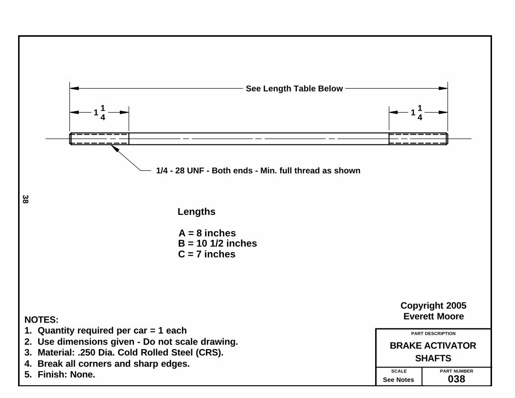
While into tread cutting, you might aswell cut the threads on all parts made fromround CRS. From your tap and die set chosethe appropriate die and die stock (the handlethat holds the die) and, after cutting the rodsto length, cut the threads per drawings No.038 and 039.
The remaining metal work entails modify-ing a purchased part, such as cross drillingand pressing in a roll-pin, drill and tappingor, in one case, cutting threads with a die.
One part, the brake activator guide, PartNo. 041 requires drilling and tapping pluspressing in two bearings.
Other modifications are self-explanatoryas per the drawing.
Now is a good time to examine all yourparts by comparing them to the drawing.Remove any burrs found, de-grease and setaside for the initial assembly process.
Collect all the motor-wheel parts and setup for welding or, if desired, taken, togetherwith drawing, to a welder for completing themotor-wheel frame.
Only after making sure that parts fit andfunction as intended, should they be de-greased, primed and painted with the finishof your choice.
_______________
22
The Making of Metal Parts

PART DESCRIPTION
MOUNTING BRACKETFRONT SPINDLE
PART NUMBER
023SCALE
See Notes
Copyright 2004Everett Moore
23
NOTES:1. Quantity required per car: 42. Use dimensions given - Do not scale drawing.3. Material: 1/4 X 1-1/2 Steel Bar Stock.4. Break all corners and sharp edges.5. Finish: Choice of builder.
.750
2.250
4.125
1 12 R
1 12
1116
5 58
.375 DIA (2)
.625 DIA

PART DESCRIPTION
BRAKE ARMINTERMEDIATE
PART NUMBER
024SCALE
See Notes
Copyright 2005Everett Moore
24
NOTES:1. Quantity required per car: 12. Use dimensions given - Do not scale drawing.3. Material: 1/4 x 1” steel bar stock.4. Break all corners and sharp edges.5. Finish: Builder’s choice.
3.50
.50 R
.312 DIA
.50
.250 DIA4 holes
7.00
8.00
9.00
10.00 (ref)

PART DESCRIPTION
MOUNTING BRACKETBRAKE PEDAL
PART NUMBER
025SCALE
See Notes
Copyright 2006Everett Moore
25
NOTES:1. Quantity required per car: 12. Use dimensions given - Do not scale drawing.3. Material: Make from purchased part per drawing callout.4. Break all corners and sharp edges.5. Finish: Builders choice.
1116 1 12
58
516 DIA
.625 Dia (ref)
PP 242

PART DESCRIPTION
WASHER PLATE
PART NUMBER
026SCALE
See Notes
Copyright 2005Everett Moore
26
NOTES:1. Quantity required per car = (4)2. Use dimensions given - Do not scale drawing.3. Material: 1/8 x 1 Bar stock.4. Break all corners and sharp edges.5. Finish: Choice of builder.
38 1 14
2
932 DIA
12
1

PART DESCRIPTION
ASSEMBLYBRAKE PEDAL
PART NUMBER
027SCALE
See Notes
Copyright 2005Everett Moore
27
NOTES:1. Quantity required per car: 12. Weld components as shown.3. Material: 1/4 X 1 Steel bar stock & .625 dia CRS.4. Finish: Choice of builder.
3.75
18
316.50
1.00
1.00
1.00
1 58
414 R
34
7 78
3 316
.125 dia
.625 dia CRS
Weld all around
.250 DIA
.625 DIA
3 holes
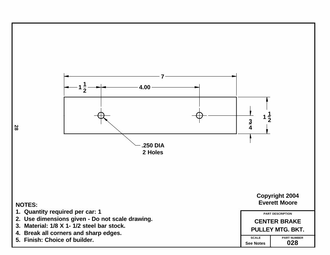
PART DESCRIPTION
PULLEY MTG. BKT.CENTER BRAKE
PART NUMBER
028SCALE
See Notes
Copyright 2004Everett Moore
28
NOTES:1. Quantity required per car: 12. Use dimensions given - Do not scale drawing.3. Material: 1/8 X 1- 1/2 steel bar stock.4. Break all corners and sharp edges.5. Finish: Choice of builder.
7
4.001 12
.250 DIA2 Holes
34
1 12

PART DESCRIPTION
PULLEY MTG. BKT.OUTBOARD BRAKE
PART NUMBER
029SCALE
See Notes
Copyright 2004Everett Moore
29
NOTES:1. Quantity required per car: 1 Left Hand & 1 Right Hand.2. Use dimensions given - Do not scale drawing.3. Material: 1/8 X 1- 1/2 Steel Bar Stock4. Twist bend as shown to allow brake cable to go under chassis board.4. Break all corners and sharp edges.5. Finish: Choice of builder.
1 12 4.50 6.00
13
11 12
12°
34
1 12
.250 DIA
.375 DIA2 Holes
Twisting bend to be within this area
LH as shown (Qty 1)
18 R
RH to be mirrow image (Qty 1)
A =
B =
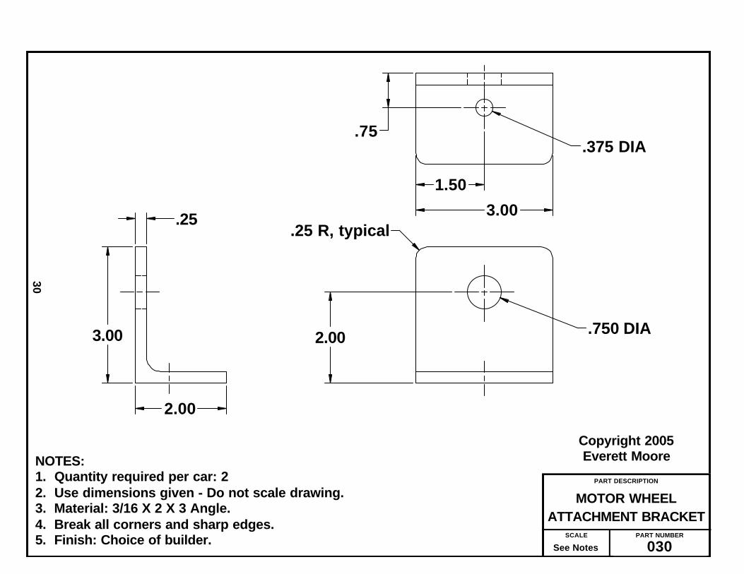
PART DESCRIPTION
ATTACHMENT BRACKETMOTOR WHEEL
PART NUMBER
030SCALE
See Notes
Copyright 2005Everett Moore
30
NOTES:1. Quantity required per car: 22. Use dimensions given - Do not scale drawing.3. Material: 3/16 X 2 X 3 Angle.4. Break all corners and sharp edges.5. Finish: Choice of builder.
.375 DIA
.25 R, typical.25
1.50
3.00
2.003.00
2.00
.75
.750 DIA

PART DESCRIPTION
MOUNTING BKT - LHBRAKE ANCHOR
PART NUMBER
031SCALE
See Notes
Copyright 2005Everett Moore
31
NOTES:1. Quantity required per car: 12. Use dimensions given - Do not scale drawing.3. Material: 3/16 X 2 X 2 Angle.4. Break all corners and sharp edges.5. Finish: Choice of builder.
.375 DIA
1 12
1
22
3 HOLES 5
5 34
78
12
14 R
12 R

PART DESCRIPTION
MOUNTING BKT - RHBRAKE ANCHOR
PART NUMBER
032SCALE
See Notes
Copyright 2005Everett Moore
32
NOTES:1. Quantity required per car: 12. Use dimensions given - Do not scale drawing.3. Material: 3/16 X 2 X 2 angle4. Break all corners and sharp edges.5. Finish: Choice of builder.
.375 DIA
3 HOLES
1 12
121
2
2
78
5
5 34
14 R 1
2 R

PART DESCRIPTION
LEVER MTG BKTINTERMEDIATE BRAKE
PART NUMBER
033SCALE
See Notes
Copyright 2005Everett Moore
33
NOTES:1. Quantity required per car: 12. Use dimensions given - Do not scale drawing.3. Material: 3/16 - 2 x 3 Angle & 3/16 x 1 1/2 bar stock.4. Break all corners and sharp edges.5. Finish: Choice of builder.
4
1 12
3
1434
1 12
412 (ref)
516 DIA Weld
1
2
12
3
38 DIA
14 R (typical)
2 Holes
PART DESCRIPTION
FLANGE - ALTERNATIVEHUB MOUNTING
PART NUMBER
034SCALE
See Notes
Copyright 2004Everett Moore
34
NOTES:1. Quantity required per car: 22. Use dimensions given - Do not scale drawing.3. Material: See drawing callout.4. Break all corners and sharp edges.5. Finish: Choice of builder.
Make from 3 1/2" Dia. Aluminum discMcMaster-Carr No. 9035K17 - PP 248
5/16 x 24 UNF4 holes
2.812 DIA
2.000 DIA
1/4 x 28 UNF4 holes
1-5/8 DIA
3-1/2 DIA (ref)
.50 (REF)

PART DESCRIPTION
WHEEL/FLANGE DRILLCARDBOARD TOOL
PART NUMBER
035SCALE
See Notes
Copyright 2004Everett Moore
35
NOTES:1. Quantity required per car: 12. Use dimensions given - Do not scale drawing.3. Material: Cardboard such as on back of writing tablets, poster board, etc.4. Cut stack of small disks to be snug fit in wheel bearing hole. (approx 1.375).5. Glue stack of small disks concentrically on large disk. This stack must be
sufficient to firmly locate tool in wheel hub.6. Make small pin hole at intersection of all 8 hole locations.
3 12 DIA
2 1316 DIA
1 1332 R
2 DIA
1 R
1 1132 DIA
*
Location of pin holesTypical 8 places

PART DESCRIPTION
COMP0NENT PIECESWHEEL SUPPORT
PART NUMBER
036SCALE
See Notes
Copyright 2005Everett Moore
36
NOTES:1. Quantity required per car = 2 each2. Use dimensions given - Do not scale drawing.3. Material: 3/16 x 2 bar stock.4. Break all corners and sharp edges.5. Finish: Finished after final weldment.
1.00 R
.750 DIA
.50 R
.50 R
8 12 (ref)
Mat'l = 3/16 bar stock
C B A
5 126 12
7 12
22
2

PART DESCRIPTION
TUBULAR NUT
PART NUMBER
037SCALE
See Notes
Copyright 2004Everett Moore
37
NOTES:1. Quantity required per car: 42. Use dimensions given - Do not scale drawing.3. Material: 5/8 Dia CRS4. Break all corners and sharp edges.5. Finish: Choice of builder.
58 DIA
5/16 - 24 UNF
34
1 12
PART DESCRIPTION
SHAFTSBRAKE ACTIVATOR
PART NUMBER
038SCALE
See Notes
Copyright 2005Everett Moore
38
NOTES:1. Quantity required per car = 1 each2. Use dimensions given - Do not scale drawing.3. Material: .250 Dia. Cold Rolled Steel (CRS).4. Break all corners and sharp edges.5. Finish: None.
1/4 - 28 UNF - Both ends - Min. full thread as shown
See Length Table Below
Lengths
A = 8 inchesB = 10 1/2 inchesC = 7 inches
1 141 14

PART DESCRIPTION
TIE RODS - A & B
PART NUMBER
039SCALE
See Notes
Copyright 2004Everett Moore
39
NOTES:1. Quantity required per car: 1 “A” & 1 “B”2. Use dimensions given - Do not scale drawing.3. Material: Per drawing callout.4. Break all corners and sharp edges.5. Finish: Choice of builder.6. Assemble each Tie Rod with lock nut and ball end on each end. Screw on
far enough to keep together as a unit. Do not tighten until final assembly.
Make from 3/8 dia CRS
3/8 - 24 UNF - Min 1-1/2" full thd - both ends
3/8 - 24 Nut (4 req"d)
Tie Rod "A" = 7 in. Long
Tie Rod "B" = 23 3/8 long
3/8 - 24 Ball end - No. PP 203 (4 req'd)

PART DESCRIPTION
DIAGONAL BRACE
PART NUMBER
040SCALE
See Notes
Copyright 2005Everett Moore
40
NOTES:1. Quantity required per car: 22. Use dimensions given - Do not scale drawing.3. Material: 1/8 X 3/4 bar stock.4. Break all corners and sharp edges.5. Finish: Choice of builder.
8 2132
38
38
34
9 1332
.250 dia - 2 holes38 R

PART DESCRIPTION
GUIDEBRAKE ACTIVATOR
PART NUMBER
041SCALE
See Notes
Copyright 2004Everett Moore
41
NOTES:1. Quantity required per car: 12. Use dimensions given - Do not scale drawing.3. Material: Per drawing callout. The builder has lattitude to utilize what ever
is on hand to build this guide. 4. Break all corners and sharp edges.5. Press bearings in flush with flange (both ends). The .250 hole thru bearings
must be aligned and free for movement of activator shaft. This may require running drill through holes after assembly.
6. Finish: Choice of builder.
58
34 1 12
3" (ref)
1 14 (ref) 12
14 (ref)
1/4 - 28 UNF - 2 holes
.375 DIA - thru both ends
1 (ref)
PP 242
PP 243 (2)
14 DIA
See notes

PART DESCRIPTION
LINKBRAKE ACTIVATOR
PART NUMBER
042SCALE
See Notes
Copyright 2004Everett Moore
42
NOTES:1. Quantity required per car: 12. Use dimensions given - Do not scale drawing.3. Material: Make from PP 244 - No. 6065K131 (McMaster - Carr)4. Break all corners and sharp edges.5. Finish: Choice of builder.
.250 DIA 1/4 -28 UNF
1 12Min full thd
3 (ref)
PP 244
Make from Rod End Blank, McMaster Carr No. 6065K131

PART DESCRIPTION
ANCHOR BOLTBRAKE BAND
PART NUMBER
043SCALE
See Notes
Copyright 2004Everett Moore
43
NOTES:1. Quantity required per car: 22. Use dimensions given - Do not scale drawing.3. Material: Make from 3/8 x 24 UNF bolt.4. Cross drill .125 dia as shown.5. Break all corners and sharp edges.6. Press roll pin thru bolt flush with opposite side.7. Finish: Choice of builder.
2 14
12
1/8 x 3/4 Roll pin1
1 in. before threads

PART DESCRIPTION
ANCHOR PINBRAKE BAND
PART NUMBER
044SCALE
See Notes
Copyright 2004Everett Moore
44
NOTES:1. Quantity required per car: 22. Use dimensions given - Do not scale drawing.3. Material: .375 dia. Cold rolled steel (CRS) or make from Cable Pins,
Part. No. 13663 (Northern Tool)4. Break all corners and sharp edges.5. Press roll pin thru until flush with with opposite side.6. Finish: Choice of builder.
12
1/8 x 3/4 Roll pin1
.375 DIA - CRS
38 (ref)
.125 Dia.

PART DESCRIPTION
MODIFICATIONREAR HUB
PART NUMBER
045SCALE
See Notes
Copyright 2004Everett Moore
45
NOTES:1. Quantity required per car: 22. Material: Per callout on drawing.3. Carefully remove bearing from one side.4. Use dimensions given - Do not scale drawing.5. Remove burrs after drilling.6. Finish: Paint metal exposed by drilling. Color: Choice of builder.
on 2.000 dia BC4 holes, evenly spaced
Only hub is shown for clarity.
17/64 Dia.
Rear Wheel (Purchased Part No. 206)

PART DESCRIPTION
PLATEPIVOT SUPPORT
PART NUMBER
046SCALE
See Notes
Copyright 2005Everett Moore
46
NOTES:1. Quantity required per car: 22. Use dimensions given - Do not scale drawing.3. Material: 3/16 x 3 bar stock.4. Break all corners and sharp edges.5. Finish: Finished at welded assembly.
1
4 12
1
3
12 R

PART DESCRIPTION
THROTTLE MTG BKT
PART NUMBER
047SCALE
See Notes
Copyright 2004Everett Moore
47
NOTES:1. Quantity required per car = 12. Use dimensions given - Do not scale drawing.3. Material: 1 x 1/8 Aluminum bar stock.4. Finish: Natural
38 2 14
1 12
3
12
1
38 DIA
316 DIA 2 holes

PART DESCRIPTION
A & BSTEERING SHAFT
PART NUMBER
048SCALE
See Notes
Copyright 2004Everett Moore
48
NOTES:1. Quantity required per car: 1 each.2. Use dimensions given - Do not scale drawing.3. Material: Make from purchased parts per drawing callout.4. Break all corners and sharp edges.5. Finish: Choice of builder.
SHAFT "A" (1 Req'd)
SHAFT "B" (1 Req'd)
PP 232
Make from PP 233
15 12
24 (REF)

You will find that there are some partsthat can best be assembled as a sub-assemblyand then, be attached to the final assembly asa unit.
Starting at the front of the car: the frontaxle can be done as a sub-assembly per draw-ing No. 054.
The brake mechanism as depicted ondrawing No. 050 can be partially assembledas a sub- assembly.
The motor wheel itself is a sub-assemblywith some of its components put together assub-assemblies.
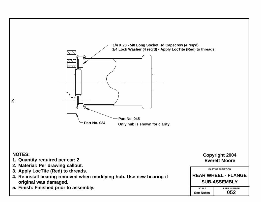
The next two sub-assemblies are a bitmore difficult. Referring to drawing No. 052,you will see how the adapter, Part No. 034 isattached to a rear wheel. While we do notpower either wheel, both wheels have brakedrums and require both rear wheels to havethis adapter attached.
Originally, we fastened the adapter andwheel with 1/4-28 socket-head cap screwsand split lockwasher. However, this tended toloosened up..
Therefore, we now recommend that, inaddition to the lockwasher, the threads becoated with LocTite (Red), making a semi-
permanent assembly.The inner bearing of the wheel had to be
removed for the drilling of the four holes asshown in drawing No. 045. The bearing is notreplaced until after the mounting flange hasbeen attached.
Doing the above described assemblyrequires working in very tight quarters. Along, ball end allen wrench is used to insertand turn the Allen Head screws from theopening in the opposite bearing.
After applying LocTite, tighten all fourscrews as tight as you can get them — justshort of breaking the ball end off yourwrench. Hopefully, this is the last time youhave to do this.
With the two rear wheels thus done, youmight as well proceed to finishing up the rearwheels by attaching the discs and brakedrums per drawing No. 053.
The purpose of these discs is to help keepthe brake bands in place.
The front axle can either be sub-assem-bled separately or after it is attached to thechassis board. I prefer the latter. In eithercase it is depicted on drawing No. 054.
49
The Sub-Assembly Process

PART DESCRIPTION
ASSEMBLYBRAKE ACTIVATOR
PART NUMBER
050SCALE
See Notes
Copyright 2006Everett Moore
50
NOTES:1. Quantity required per car: 13. Material: Per drawing callout4. Finish: Choice of builder.5. Add a compression spring to area indicated to achieve desired
brake return.6. Adjust so that when lever No. 024 is upright (as shown)
there’s sufficient release of brake bands.7. Adjust brake pedal No. 027 to suit operator.
042
1/4 - 28 Hex Nut (4)
PP 214 )ref)
On final assembly, useLoctite (blue) on coupling nut
033 038A
038B
024
025
027038C
PP 214 (5)PP 240 (5)PP 241 (5)
PP 214 (ref)PP 240 (ref)PP 241 (ref)
041
See Notes
Note: It may be necessaryto file clevis in this areafor free turning of pulley
PP 235 (1)
On final assembly, useLoctite (blue) on these 2 capscrews
PP 231

PART DESCRIPTION
JACKSHAFTMOTOR WHEEL
PART NUMBER
051SCALE
See Notes
Copyright 2006Everett Moore
51
NOTES:1. Quantity required per car: 12. Use dimensions given - Do not scale drawing.3. Material: .750 Dia CRS with full keyway4. Break all corners and sharp edges.5. Finish: None
11 34
.750 DIA (ref)
.050 R (typical)
PART DESCRIPTION
SUB-ASSEMBLYREAR WHEEL - FLANGE
PART NUMBER
052SCALE
See Notes
Copyright 2004Everett Moore
52
NOTES:1. Quantity required per car: 22. Material: Per drawing callout. 3. Apply LocTite (Red) to threads.4. Re-install bearing removed when modifying hub. Use new bearing if
original was damaged.5. Finish: Finished prior to assembly.
1/4 X 28 - 5/8 Long Socket Hd Capscrew (4 req'd)
Only hub is shown for clarity.Part No. 045
Part No. 034
1/4 Lock Washer (4 req'd) - Apply LocTite (Red) to threads.

PART DESCRIPTION
GUIDE DISC & DRUM REAR WHEEL ASS’Y -
PART NUMBER
053SCALE
See Notes
Copyright 2006Everett Moore
53
NOTES:1. Quantity required per car: 22. Material: Per callout on drawing.3. Finish: Parts are pre-finished at assembly
5/16 x 24 UNF - 7/8 Long Socket Head C'Screw
4 each req'd
Wheel Sub-Assembly Part No. 052Brake Drum - PP No. 223
5/16 Lock Washer Plus use LocTite (red)
075

PART DESCRIPTION
ASSEMBLYFRONT AXLE
PART NUMBER
054SCALE
See Notes
Copyright 2004Everett Moore
54
NOTES:1. Quantity required per car: 12. Use dimensions given - Do not scale drawing.3. Material: Per drawing callout.4. Break all corners and sharp edges.5. Finish: Parts to be finished before assembly.6. Add 3/8 fender washers to lower spindle brackets as necessary to obtain
proper fit of spindle.
PP 202 PP 228 (2)
PP 201 PP 228 (2)
023 (4) 014
Adjust spacing between brackets, if needed, by placing large, fender washers between lower brackets and wood.

PART DESCRIPTION
BASE ANGLEJACKSHAFT
PART NUMBER
055SCALE
See Notes
Copyright 2005Everett Moore
55
NOTES:1. Quantity required per car: 22. Use dimensions given - Do not scale drawing.3. Material: 1/8 x 1 angle.4. Break all corners and sharp edges.5. Finish: Choice of builder.
2 34 6 1212
1 6
9 34
58
12
.250 Dia - 2 holes
.312 dia - 2 holes
12 R
A = Left side as shown
B = Right side mirrow image of left

PART DESCRIPTION
UPRIGHT ANGLESJACKSHAFT
PART NUMBER
056SCALE
See Notes
Copyright 2005Everett Moore
56
NOTES:1. Quantity required per car: 2 of A & 2 of B2. Use dimensions given - Do not scale drawing.3. Material: 1/8 x 1 angle.4. Break all corners and sharp edges.5. Finish: Choice of builder.
12 2
7 3438 (ref)
12
.250 Dia
Dimensions are same for both parts
12 R
B = Left (2)
A = Right (2)

PART DESCRIPTION
MOUNTING PLATEBEARING
PART NUMBER
057SCALE
See Notes
Copyright 2005Everett Moore
57
NOTES:1. Quantity required per car: 22. Use dimensions given - Do not scale drawing.3. Material: 1/8 x 3 bar stock.4. Break all corners and sharp edges.5. Finish: Choice of builder.
12
3 141 25
32 1 2532
6 12
7 12
12
34
2
3
.250 Dia - 4 holes
7/16 Dia - 2 holes
1 DiaBearing Mounting Plate (2)

PART DESCRIPTION
BOTTOM VIEWCHASSIS ASSEMBLY -
PART NUMBER
058SCALE
See Notes
Copyright 2006Everett Moore
58
NOTES:1. Quantity required per car: 12. Parts locate per previously drilled holes.3. Material: Per drawing callout.4. Assemble per intructions in text.
PP 236
054
039A
039B
010
020
021
029A PP 235
029B PP 235
015
050 028
PP 235 (2)
026
026

PART DESCRIPTION
TOP VIEWCHASSIS ASSEMBLY -
PART NUMBER
059SCALE
See Notes
Copyright 2006Everett Moore
59
NOTES:1. Quantity required per car: 12. Parts locate per previously drilled holes.3. Material: Per drawing callout.4. Assemble per intructions in text.5. ** Throttle cable exit location determined by engine used.
030 (2)
065 013
For brake detail see drawing 050
017
Attach brake actuator ass'y (below) with 1.4-28 x 1" caoscrews & washers Bolt heads must not interfer with Seat support (017). Secure with LocTite (Blue).
**
PP 251 (ref)

PART DESCRIPTION
SIDE VIEWCHASSIS ASSEMBLY
PART NUMBER
060SCALE
See Notes
Copyright 2006Everett Moore
60
NOTES:1. Dis-assemble pillow blocks No. PP 204 and re-assemble with oil cup out
side instead of top hole. This will allow extreme movement of bearingnecessary to match angle of steering shaft.
2. Position the steering shaft to clear front axle by 1/4” and secure in placewith Collars PP 212 and Bearings PP 229.
3. Attach seat to support with 2-1/2” removable pin hinges (2)4. Throttle cable to be mounted 1” below top edge of seat support.
016 037 (4)
068
018
PP 226 PP227
Mtg. flange included with 048B
048B
PP 204 (2)
PP 212 (2) PP 229 (2)
PP 234
048A
For brake detail see drawing 050
For detail see drawing 061
See notes
067
030 (2) (ref)
14
PP 251
047
Length of throttle cable extending and wire end bendingto be determined when engine wheel is mounted

PART DESCRIPTION
SHAFT ASS’Y DETAILSTIE ROD - STEERING
PART NUMBER
061SCALE
See Notes
Copyright 2004Everett Moore
61
NOTES:1. Assemble as shown.2. End of steering shaft to be 1/4” from front axle.2. Use shim washers as shown to premit maximum tie rod travel.3. Secure nuts with LocTite (blue)
PP XXX (typical)
PP XXX (typical)
Apply LocTite (Blue) 2 places
PP 210 (typical)
PP 211 (typical)
Apply LocTite (Blue) 2 places
1/4

PART DESCRIPTION
FINAL WELDMENTMAIN FRAME
PART NUMBER
062SCALE
See Notes
Copyright 2005Everett Moore
62
NOTES:1. Quantity required per car: 12. Use dimensions given - Do not scale drawing.3. Material: Per drawing callout.4. Engine mounting plate is P/N AZ8190 from Manufacturers Supply5. Break all corners and sharp edges.5. Finish: Choice of builder.
5 1217
125 38
1 1/2 x 1 1/2 x .120 Sq Tube 2 pieces - 5 3/8 Lg.
5 (ref)
1" x 1" x .120 Sq Tube - 8 3/8 Lg.
Weld according to accepted welding practices
063 RH
063 LH
046 (2)
PP 250

PART DESCRIPTION
SIDE WELDMENTMAIN FRAME
PART NUMBER
063SCALE
See Notes
Copyright 2005Everett Moore
63
NOTES:1. Quantity required per car: 2, 1 RH & 1LH2. Use dimensions given - Do not scale drawing.3. Material: Per drawing callouts.4. Break all corners and sharp edges.5. Finish: Finished at final welded assembly.
1 1/2 x 1 1/2 x .120 Sq Tubing
Weld
Right side shownLeft side is mirrow image
32 12
036-C
036-B
036-A
046 (2)
073

PART DESCRIPTION
INSTALLATIONBRAKE BAND
PART NUMBER
064SCALE
See Notes
Copyright 2005Everett Moore
64
NOTES:1. Quantity required per car: 2 (left and right)2. Loosely assemble anchor bolt (043) at this stage. Final adjustment are
made to it and brake cable after rear wheels are mounted.3. Secure brake cable with standard clamp from hardware store.4. Roll-pins of parts 043 and 044 are positioned approximately as shown.
PP 224 (2)
031 (Left ) 032 (Right )
043
044

PART DESCRIPTION
DETAILSAXLE - HUBCAP
PART NUMBER
065SCALE
See Notes
Copyright 2004Everett Moore
65
NOTES:
1. Use dimensions shown. Do not scale drawing.2. Axle = 3/4 dia CRS cut oversize (48”) - Push axle thru axle tube on frame - Install shim
washers and 1 wheel as show above - Install 1 hub cap, cross drill, install cotterpin - Install shim washers and 2nd wheel - Allowing extra length for hub cap,cut off - Install hub cap - cross drill - Install 2nd cotter pin.
3. Add or remove 1/32 shim washers to allow wheels to turn freely without excess-sive end play.
1/8 shim washer
1/32 shim washer (as needed)
Make from 1/2 in pipe capDrill out to 3/4 dia. - cross drill 5/32 dia.
Attach entire assembly to axle with 5/32 cotter pin
See notes about axle length
053 (2) (wheel)

PART DESCRIPTION
ASSEMBLYDRIVE WHEEL
PART NUMBER
066SCALE
See Notes
Copyright 2006Everett Moore
66
NOTES:1. Quantity required per car: 12. Material: Worksman Wheel, Tire, Tube & Strip. Whizzer Motorbike Sheave.
Callouts refer to purchased part list.3. Finish: Parts are plated.4. Using Clips (PP 239), mount Sheave (PP 238) to spokes of wheel. Use care
to get sheave concentric with axle/hub.
A
ASection A - A
PP 207 PP 216 PP 220 PP 221
PP 238 PP 239 (9)

PART DESCRIPTION
SEAT CUSHION BASE
PART NUMBER
067SCALE
See Notes
Copyright 2004Everett Moore
67
NOTES:1. Quantity required per car: 12. Use dimensions given - Do not scale drawing.3. Material: 1/2 inch plywood - 1/4 - 20 x 5/16 “T” nuts (4) - PP 2494. Break all corners and sharp edges.5. Finish: None.6. Suggest using 2 in. of foam covered with appropriate upholstery material
stretched tight and stapled in back. Be sure and not cover up the mountingholes. Alternate: Take to an upholstery shop and let them cover it.
Section A - A 4:1
7 14 21
35 12
AA
11
14
1 12
5/16 dia C'bore 1" dia 1/16 deep
Press 1/4 - 20 "T" nut flushTypical 4 places

PART DESCRIPTION
CUSHION BASESEAT BACK
PART NUMBER
068SCALE
See Notes
Copyright 2004Everett Moore
68
NOTES:1. Quantity required per car: 12. Use dimensions given - Do not scale drawing.3. Material: 1/2 inch plywood - 1/4 - 20 x 5/16 “T” nuts (3) - PP 2494. Break all corners and sharp edges.5. Finish: None.6. Suggest using 2 in. of foam covered with appropriate upholstery material
stretched tight and stapled in back. Be sure and not cover up the mountingholes. Alternate: Take to an upholstery shop and let them cover it.
Section A - A 4:1
Press 1/4 - 20 "T" nut flush
AA
Typical 3 places
7 12
3 34
32
16
5 12
43
4 R
1 R
5/16 dia C'bore 3/4" dia 1/16 deep

PART DESCRIPTION
ASSEMBLYJACKSHAFT
PART NUMBER
069SCALE
See Notes
Copyright 2006Everett Moore
69
NOTES:1. Quantity required per car: 12. Material: Per drawing call out.3. After alignment of sprockets and pulleys, secure all setscrews. At final
assembly, secure all setscrews with LocTite (blue).4. Finish: n/a
070 B
070 A
051
PP 245
076

PART DESCRIPTION
SUPPORT ASSY, A & BJACKSHAFT
PART NUMBER
070SCALE
See Notes
Copyright 2006Everett Moore
70
NOTES:1. Quantity required per car: 2, 1 LH (A) & 1 RH (B)2. Material: Per drawing callout.3. Use 1/4 hardware except mounting bearing, which is 7/16.4. Use Nylon insert locknuts on all hardware.5. Finish: Parts are individually finished before assembly.
A = Left hand as shownB = Right hand to be mirrow image
074
040
055 A
056 A056 B057 PP 205

PART DESCRIPTION
FINAL ASSEMBLYMOTOR WHEEL
PART NUMBER
071SCALE
See Notes
Copyright 2006Everett Moore
71
NOTES:1. Quantity required per car: 12. Material: Per drawing callout.
060
Sprocket & Pulley not shown on Jackshaft for clarity
066062
Final jackshaft - belt - chain alignmentand tension adjustment per drawing No. 072
PP 215
PP 237
PP 252
PP 222 PP 230
For wheel and Axle assembly see Drawing No. 077

PART DESCRIPTION
ADJUSTMENTJACKSHAFT SUPPORT
PART NUMBER
072SCALE
See Notes
Copyright 2005Everett Moore
72
NOTES:1. Loosely mount to dimensions shown.2. Use dimensions given - Do not scale drawing.3. Material: Per drawing callout.
12 Initial Adjustment
2
5/16 x 24 All thread rod (2" lgth) 4 reqd.5/16 x 24 Nylon insert lock nut - 4 reqd.5/16 x 24 hex jam hut - 8 reqd.5/16 x 24 hex nut - 4 reqd.
See text foradjustment instructions
063 (ref)
070A (left side)070B (right side)(ref)

PART DESCRIPTION
MOUNTING ANGLEJACKSHAFT
PART NUMBER
073SCALE
See Notes
Copyright 2005Everett Moore
73
NOTES:1. Quantity required per car: 22. Use dimensions given - Do not scale drawing.3. Material: 1/8 x 1 angle.4. Break all corners and sharp edges.5. Finish: Finished after welded assembly.
1 6
8
12
.312 Dia
PART DESCRIPTION
SHIELD PLATE
PART NUMBER
074SCALE
See Notes
Copyright 2005Everett Moore
74
NOTES:1. Quantity required per car: 22. Use dimensions given - Do not scale drawing.3. Material: Any 18 to 20 gauge sheet metal4. Break all corners and sharp edges.5. Finish: Choice of builder.
5 34
386 12 5
16
6 12
7 18
78
3 916
1 12 R
516 DIA (4)

PART DESCRIPTION
GUIDE DISCBRAKE BAND
PART NUMBER
075SCALE
See Notes
Copyright 2005Everett Moore
75
NOTES:1. Quantity required per car: 22. Use dimensions given - Do not scale drawing.3. Material: Make from Northern sprocket p/s 1361 (PP 217)4. Break all corners and sharp edges.5. Finish: Choice of builder.
6.75 DIA
2.813 DIA
.281 DIA4 holes on a 2.813 dia BC
2.00 DIA
Make from 1/8 steel plate or machine teeth off a 60 tooth - #35 sprocket (Northern #1361)

PART DESCRIPTION
WELDED ASSEMBLYDRIVEN SPROCKET
PART NUMBER
076SCALE
See Notes
Copyright 2006Everett Moore
76
NOTES:1. Quantity required per car: 12. Use dimensions given - Do not scale drawing.3. Material: Per parts callout.4. Break all corners and sharp edges.5. Finish: Choice of builder.
PP 219
PP 218
Weld all around
#41 - 54 teeth - 8 3/4 Dia (ref)

PART DESCRIPTION
MOUNTING DETAILSDRIVE WHEEL
PART NUMBER
077SCALE
See Notes
Copyright 2005Everett Moore
77
NOTES:1. Quantity required per car: 12. Use shim washers (PP 246 & pp 247) to center wheel in frame.3. When axle bolt (PP 253) is tightened, the proper amount of shim washer willprovide a slight pre-loading on wheel bearings. ( Just enough to remove anyside play of wheel.
PP 253
PP 246 PP 247
062 (ref)
066 (ref)
5/8 - 11 Nylon stop nut

78

79
Photo shows 3/4 dia hole 1 inch down ¢ered in seat support front (017). Whenrouting throttle cable, keep sharp bend to aminimum.
This photo shows push-pull throttle (PP251) and Throttle mounting plate (047) fas-tened to front of seat support (017).
Photo above shows throttle cable exitingthe seat support box. This hole is drilled 1inch down from top edge and inward tomatch engine used.
The centrifigal clutch (PP 237) is shownabove. Note how it is retained to enginecrankshaft by a large fender washer and 5/16capscrew.
Thus, it is imparative that your enginehave the end of crankshaft drilled andtapped. This is common with most engines.

Vendor Code = FB Foley-BelsawP.O. Box 419593Kansas City, Mo 641411-800-821-3452
Vendor Code = G * W. W. Grainger, Inc.Website: www.grainger.com
Vendor Code = McC ** McMaster-CarrWebsite: www.mcmaster.com
Vendor Code = MS Manufacturer’s SupplyP.O. Box 167Dorchester, WI 544251-800-826-8563Website: www.mfgsupply.com
Vendor Code = NT Northern Tool & Equipment1-800-556-7885Website: www.NorthernTool.com
Vendor Code = SEW Small Engine Warehouse765-768-6725Website: www.smallenginewarehouse.com
Vendor Code = GKG Go-Kart Galaxy1-903-340-1965Website: www.gokartgalaxy.com
Vendor Code = AS Aircraft Spruce & Specialty Co.1-877-477-7823Website: http://www.aircraftspruce.com
Vendor Code = W Worksman1-888-394-3353
Vendor Code = WZ Whizzer U.S.A., Inc.1-972-484-9555Website: http://www.whizzermotorbike.com
* W. W. Grainger has outlets in most larger cities. You need to contact the one closest to you.Look in a phone book for a larger city near you.
** McMaster-Carr has several locations. They have such a user friendly website that theeasiest way to order from them is on the internet.
Always check our website: www.smallcarplans.com for links to the latest in suppliers.
80

PP No. Qty Description Vendor Code Catalog No.
201 1 Spindle, RH MS AZ2518
202 1 Spindle, LH MS AZ2519
203 4 Ball Joint, 3/8 - 24 MS 10-2214
204 2 Pillow Block, 5/8” Bronze G 2X529
205 2 Flange Mt. Pillow Block, 3/4” Ball Bearing NT 1805
206 4 Pneumatic Spoked Wheel, 26” NT 145123
207 1 Heavy Duty Wheel 26” W 329A
208 10 Shim Washer, 5/8 X 1 OD X .031 McC 3088A433
209 10 Shim Washer, 5/8 X 1 OD X .125 McC 3088A513
210 10 Shim Washer, 3/8 ID X 5/8 OD X .062 McC 3088A466
211 10 Shim Washer, 3/8 ID X 5/8 OD X .125 McC 3088A511
212 2 Collar, 5/8 ID MS AZ8554
213 (left blank)
214 5 Clevis, 1/4 - 28 MS AZ8354
215 1 Engine, B&S - 5.5 hp Intek or Equiv. SEW 126312
216 1 Tire, Kevlar Belted 26” W 4922AKV
217 2 Sprocket, #35 - 60 Tooth NT 1361
218 1 Sprocket, #41 - 54 Tooth NT 1363
219 1 Sprocket Hub SC 1-2343-E
220 1 Heavy Duty Tube 26” W 6023A
221 1 Rim Strip W 1017
222 10 ft. #41 Roller Chain NT 136510
223 2 4” Brake Drum MS 4-485
224 2 4” Brake Band w/pin MS 4-486
225 1 Steel shaft with Keyway 3/4” OD x 12” McC 1497K161
226 1 12” Steering Wheel MS 4-9396
227 1 Steering Wheel Cap Assembly GKG 1877
228 4 King Pin Bushing (nylon) MS AZ8215
81

PP No. Qty Description Vendor Code Catalog No.
229 2 Bronze Bushing - 5/8 ID - 3/4 OD x 1 Lg McC 6391K243
230 1 Connect Link - #41 Chain McC 6261K192
231 1 Coupling Nut - 1/4 x 28 McC 90977A140
232 1 24” Steering Shaft w/o pitman arms welded MS AZ1868-24
233 1 22” Steering Shaft w/ pitman arms welded MS AZ1867-22
234 1 5/8 x 5/8 Coupling SC 1320-0016
235 5 Control Cable Pulley AS A-124
236 15 ft Control Cable - 3/32 x 7x19 AS 05-04000
237 1 Centrifigal Clutch, Hilliard Ex Duty MS H3441
238 1 Sheave WZ 2973
239 9 Sheave Mounting Bkt/w screws WZ N-3018
240 5 Clevis Pin MS AZ8355
241 5 Cotter Pin MS AZ8419
242 2 Spindle Bracket MS AZ8171
243 2 Bronze Bearing - 1/4 ID - 3/8 OD Flanged McC 6338K413
244 1 Rod End Blank McC 6065K131
245 1 V Pulley - 1/2 w x 3.00 OD - 3/4 bore SC 1-2721
246 10 Shim Washer, 3/4 ID x 1 1/8 OD x 1/32 McC 3088A434
247 10 Shim Washer, 3/4 ID x 1 1/8 OD x 1/8 McC 3088A514
248 2 Aluminum Disc, 3 1/2 OD x 1/2 thick McC 9035K17
249 7 Tee Nut, 1/4 - 20 x 5/16 High McC 90975A025
250 1 Engine Mounting Plate MS AZ8190
251 1 Push-Pull Throttle Control FB EGR5960237
252 1 V belt - 4 L 620 (62”) **
253 1 Shoulder Bolt - .750 x 5.50 Socket Head McC 91259A857
** It is recommended that V Belt be purchased locally should a different size be required.
82

Building The 1920Briggs & Stratton CycleCar With Motor Wheel