cyber security for der, adr, and ami - eprismartgrid.epri.com/doc/20150821/3_cyber secuirty for...
TRANSCRIPT

© 2015 Electric Power Research Institute, Inc. All rights reserved.
EPRI Seminar: Integrated Grid Concept
and Technology Development
Tokyo Japan, August 20, 2015
Galen Rasche, Senior Program Manager,
Cyber Security
Cyber Security for
DER, ADR, and AMI

2© 2015 Electric Power Research Institute, Inc. All rights reserved.
Agenda
Security Trends and Challenges
Failure Scenarios for DER, ADR, and AMI
Identifying Cyber Security Requirements

3© 2015 Electric Power Research Institute, Inc. All rights reserved.
Security Trends and Challenges
4© 2015 Electric Power Research Institute, Inc. All rights reserved.
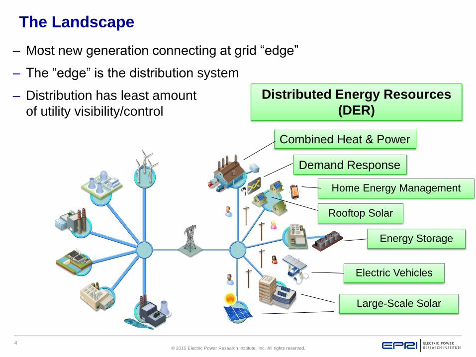
The Landscape
– Most new generation connecting at grid “edge”
– The “edge” is the distribution system
– Distribution has least amount
of utility visibility/control
Distributed Energy Resources
(DER)
Combined Heat & Power
Demand Response
Home Energy Management
Rooftop Solar
Electric Vehicles
Large-Scale Solar
Energy Storage

5© 2015 Electric Power Research Institute, Inc. All rights reserved.
Trends Impacting Security
Changing regulation
Attacks from nation states and terrorist
organizations
Connections with more business players
Reliance on external communications
Increased capability of field equipment

6© 2015 Electric Power Research Institute, Inc. All rights reserved.
Threat Model
Adversaries with intent
Insiders or outsiders, groups or individuals
Failure in people, processes, and technology,
including human error
Loss of resources, in particular key employees or
communications infrastructure
Accidents
Natural hazards as they impact cyber security
Economic
Criminals
Malicious
Criminals
Recreational
Criminals
Activist
Groups
Terrorists
Hazards
Threat Agents

7© 2015 Electric Power Research Institute, Inc. All rights reserved.
Failure Scenarios for DER, ADR, and AMI

8© 2015 Electric Power Research Institute, Inc. All rights reserved.
National Electric Sector Cybersecurity Organization Resource:
Failure Scenario Report
Includes malicious and non-malicious events
Format:
– Failure scenario description
– Relevant vulnerabilities
– Impact to grid operations
– Potential mitigations
NESCOR report includes many smart grid
scenarios:
– AMI: 32 scenarios
– DER: 25 scenarios
– ADR: 7 scenarios
– Distribution grid management: 16 scenarios
Electric Sector Failure Scenarios and Impact Analyses
9© 2015 Electric Power Research Institute, Inc. All rights reserved.
Failure Scenarios - Continued
Provide structure for modeling threats and indicators of
compromise
Can be leveraged as part of a risk assessment process
Support cyber security tabletop exercises
High-level - must be tailored to each organization
10© 2015 Electric Power Research Institute, Inc. All rights reserved.
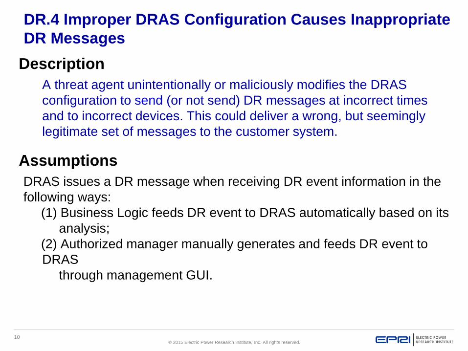
DR.4 Improper DRAS Configuration Causes Inappropriate
DR Messages
Description
A threat agent unintentionally or maliciously modifies the DRAS
configuration to send (or not send) DR messages at incorrect times
and to incorrect devices. This could deliver a wrong, but seemingly
legitimate set of messages to the customer system.
Assumptions
DRAS issues a DR message when receiving DR event information in the
following ways:
(1) Business Logic feeds DR event to DRAS automatically based on its
analysis;
(2) Authorized manager manually generates and feeds DR event to
DRAS
through management GUI.
11© 2015 Electric Power Research Institute, Inc. All rights reserved.
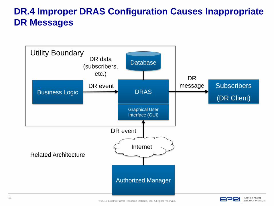
DRAS
Graphical User
Interface (GUI)
Subscribers
(DR Client)
Authorized Manager
Internet
Business Logic
Database
DR event
DR event
DR
message
DR data
(subscribers,
etc.)
Related Architecture
Utility Boundary
DR.4 Improper DRAS Configuration Causes Inappropriate
DR Messages

DR.4 Improper DRAS Configuration Causes Inappropriate DR Messages (3/4)
Possible peak energy demand; loss
of public confidence
Client receives
unintended DR message
– may continue operating
at peak demand or
curtails energy loads
Unintended DR
message is sent out
to DR Client
6
DRAS host is
compromised by
malware
Unintended DR
event is injected
into DRAS
5
Threat agent
misconfigures
DRAS to generate
unauthorized DR
event
3 4
No immediate detection;
Delayed diagnosis
13
Threat Agent Obtains
Legitimate Credentials for
Business Logic system
12
Threat Agent Gains
Access to Network
that hosts Business
Logic system
Threat agent
misconfigures
Business Logic to
feed unauthorized
DR event to DRAS
14
Threat agent creates
unauthorized DR
event via DRAS GUI
15

13© 2015 Electric Power Research Institute, Inc. All rights reserved.
Potential Mitigations
1 - See common sub tree Threat Agent Gains Access to Network <specific
network>
2 - See common sub tree Threat Agent Obtains Legitimate Credentials for
<system or function>
3 - Generate alerts on changes to configurations on DRAS; Detect unauthorized
configuration changes; Create audit log of DR messages generated; Require
second-level authentication to change configuration
5, 6 - Validate inputs, specifically the reasonableness of DR event
7 - See common sub tree Threat Agent Finds Firewall Gap
8 - See common sub tree Authorized Employee Brings Malware into <system or
network>
9, 11 - Require application whitelisting
11 - Conduct penetration testing; Perform security testing; Maintain patches in
DRAS host; Maintain anti-virus
DR.4 Improper DRAS Configuration Causes Inappropriate
DR Messages
14© 2015 Electric Power Research Institute, Inc. All rights reserved.
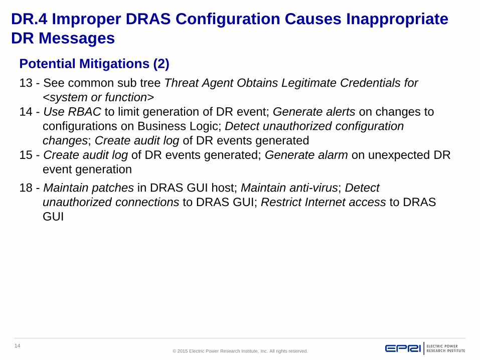
Potential Mitigations (2)
13 - See common sub tree Threat Agent Obtains Legitimate Credentials for
<system or function>
14 - Use RBAC to limit generation of DR event; Generate alerts on changes to
configurations on Business Logic; Detect unauthorized configuration
changes; Create audit log of DR events generated
15 - Create audit log of DR events generated; Generate alarm on unexpected DR
event generation
18 - Maintain patches in DRAS GUI host; Maintain anti-virus; Detect
unauthorized connections to DRAS GUI; Restrict Internet access to DRAS
GUI
DR.4 Improper DRAS Configuration Causes Inappropriate
DR Messages

15© 2015 Electric Power Research Institute, Inc. All rights reserved.
Identifying Cyber Security Requirements
16© 2015 Electric Power Research Institute, Inc. All rights reserved.
Market
Enterprise
Operation
Station
Field
Process
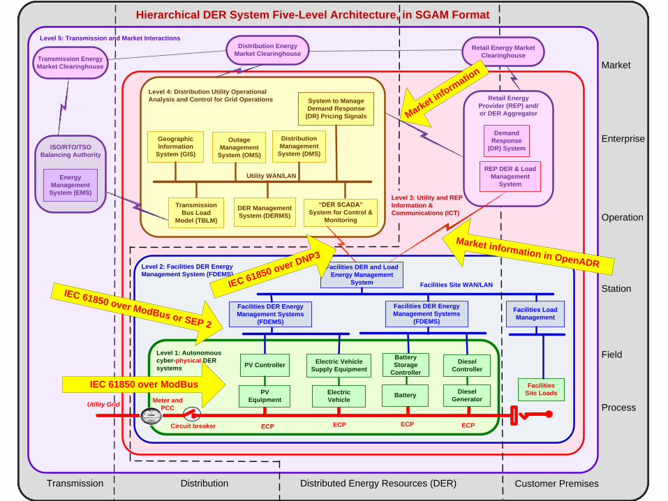
Hierarchical DER System Five-Level Architecture, in SGAM Format
Distributed Energy Resources (DER) Customer PremisesTransmission Distribution
Market
Enterprise
Operation
Station
Field
Process
Hierarchical DER System Five-Level Architecture, in SGAM Format
Utility Grid
Facilities
Site Loads
Circuit breaker
Meter and
PCC
Level 1: Autonomous
cyber-physical DER
systems
PV
Equipment
Electric
Vehicle
PV ControllerElectric Vehicle
Supply Equipment
Battery
Storage
Controller
BatteryDiesel
Generator
Diesel
Controller
Distributed Energy Resources (DER) Customer PremisesTransmission Distribution
ECP ECPECPECP
Market
Enterprise
Operation
Station
Field
Process
Hierarchical DER System Five-Level Architecture, in SGAM Format
Utility Grid
Facilities
Site Loads
Circuit breaker
Meter and
PCC
Level 2: Facilities DER Energy
Management System (FDEMS)
Level 1: Autonomous
cyber-physical DER
systems
Facilities DER Energy
Management Systems
(FDEMS)
Facilities Site WAN/LAN
Facilities DER Energy
Management Systems
(FDEMS)
Facilities DER and Load
Energy Management
System
PV
Equipment
Electric
Vehicle
PV ControllerElectric Vehicle
Supply Equipment
Battery
Storage
Controller
BatteryDiesel
Generator
Diesel
Controller
Distributed Energy Resources (DER) Customer PremisesTransmission Distribution
ECP ECPECPECP
Facilities Load
Management
Market
Enterprise
Operation
Station
Field
Process
Hierarchical DER System Five-Level Architecture, in SGAM Format
Level 4: Distribution Utility Operational
Analysis and Control for Grid Operations
“DER SCADA”
System for Control &
Monitoring
Utility Grid
Facilities
Site Loads
Circuit breaker
Meter and
PCC
Level 2: Facilities DER Energy
Management System (FDEMS)
Level 1: Autonomous
cyber-physical DER
systems
Facilities DER Energy
Management Systems
(FDEMS)
Facilities Site WAN/LAN
Facilities DER Energy
Management Systems
(FDEMS)
Facilities DER and Load
Energy Management
System
PV
Equipment
Electric
Vehicle
PV ControllerElectric Vehicle
Supply Equipment
Battery
Storage
Controller
BatteryDiesel
Generator
Diesel
Controller
Distributed Energy Resources (DER) Customer PremisesTransmission Distribution
ECP ECPECPECP
Level 3: Utility and REP
Information &
Communications (ICT)
Retail Energy
Provider (REP) and/
or DER Aggregator
REP DER & Load
Management
System
Facilities Load
Management
Market
Enterprise
Operation
Station
Field
Process
Hierarchical DER System Five-Level Architecture, in SGAM Format
Level 4: Distribution Utility Operational
Analysis and Control for Grid Operations
DER Management
System (DERMS)
Distribution
Management
System (DMS)
Outage
Management
System (OMS)
System to Manage
Demand Response
(DR) Pricing Signals
Transmission
Bus Load
Model (TBLM)
“DER SCADA”
System for Control &
Monitoring
Utility Grid
Facilities
Site Loads
Circuit breaker
Meter and
PCC
Level 2: Facilities DER Energy
Management System (FDEMS)
Level 1: Autonomous
cyber-physical DER
systems
Facilities DER Energy
Management Systems
(FDEMS)
Facilities Site WAN/LAN
Utility WAN/LAN
Facilities DER Energy
Management Systems
(FDEMS)
Facilities DER and Load
Energy Management
System
PV
Equipment
Electric
Vehicle
PV ControllerElectric Vehicle
Supply Equipment
Battery
Storage
Controller
BatteryDiesel
Generator
Diesel
Controller
Distributed Energy Resources (DER) Customer PremisesTransmission Distribution
ECP ECPECPECP
Geographic
Information
System (GIS)
Level 3: Utility and REP
Information &
Communications (ICT)
Retail Energy
Provider (REP) and/
or DER Aggregator
REP DER & Load
Management
System
Facilities Load
Management
Market
Enterprise
Operation
Station
Field
Process
Transmission Energy
Market Clearinghouse
ISO/RTO/TSO
Balancing Authority
Hierarchical DER System Five-Level Architecture, in SGAM Format
Level 4: Distribution Utility Operational
Analysis and Control for Grid Operations
DER Management
System (DERMS)
Distribution
Management
System (DMS)
Outage
Management
System (OMS)
System to Manage
Demand Response
(DR) Pricing Signals
Transmission
Bus Load
Model (TBLM)
“DER SCADA”
System for Control &
Monitoring
Utility Grid
Facilities
Site Loads
Circuit breaker
Meter and
PCC
Level 2: Facilities DER Energy
Management System (FDEMS)
Level 1: Autonomous
cyber-physical DER
systems
Level 5: Transmission and Market Interactions
Facilities DER Energy
Management Systems
(FDEMS)
Facilities Site WAN/LAN
Utility WAN/LAN
Facilities DER Energy
Management Systems
(FDEMS)
Facilities DER and Load
Energy Management
System
PV
Equipment
Electric
Vehicle
PV ControllerElectric Vehicle
Supply Equipment
Battery
Storage
Controller
BatteryDiesel
Generator
Diesel
Controller
Distributed Energy Resources (DER) Customer PremisesTransmission Distribution
ECP ECPECPECP
Geographic
Information
System (GIS)
Energy
Management
System (EMS)Level 3: Utility and REP
Information &
Communications (ICT)
Retail Energy
Provider (REP) and/
or DER Aggregator
Demand
Response
(DR) System
REP DER & Load
Management
System
Facilities Load
Management
Distribution Energy
Market ClearinghouseRetail Energy Market
Clearinghouse
IEC 61850 over DNP3
IEC 61850 over ModBus or SEP 2
Market information in OpenADR
Market i
nform
ation
IEC 61850 over ModBus

17© 2015 Electric Power Research Institute, Inc. All rights reserved.
NIST Interagency Report (NISTIR) 7628, Guidelines for Smart
Grid Cyber Security
What it IS
– May be used as a guideline to evaluate the overall cyber security
risks to a Smart Grid system
– Each organization must develop its own cyber security strategy
(including a risk assessment methodology) for the Smart Grid
What it IS NOT
– It does not prescribe particular solutions
– It is not mandatory
Version 1.0 Rev 1 published September 2014
– http://nvlpubs.nist.gov/nistpubs/ir/2014/NIST.IR.7628r1.pdf
18© 2015 Electric Power Research Institute, Inc. All rights reserved.
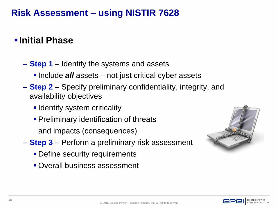
Risk Assessment – using NISTIR 7628
Initial Phase
– Step 1 – Identify the systems and assets
Include all assets – not just critical cyber assets
– Step 2 – Specify preliminary confidentiality, integrity, and
availability objectives
Identify system criticality
Preliminary identification of threats
and impacts (consequences)
– Step 3 – Perform a preliminary risk assessment
Define security requirements
Overall business assessment

19© 2015 Electric Power Research Institute, Inc. All rights reserved.
DER Logical Reference Model Extended/Modified from the NISTIR
7628 Spaghetti Diagram
19 - Energy
Market
Clearinghouse U20
29a - DER
SCADA 27 - Distribution
Management
System (DMS)
U9
5 - Customer Energy
Management
System (CDEMS)
U45
31 - ISO/RTO
Operations
U57
U56
U58
25 - Distributed
Generation &
Storage
Management
(DERMS)
U62
U65
U52
Service
Providers
Operations
Customer
Distribution
Markets
Transmission
Bulk
Generation
Domain Color Key
D06
D02
D04 D05
D03
41a - Retail
Energy
Provider (REP)
17 - Geographic
Information
System (GIS)
U102
D01
32 - Load Management
System / Demand-
Response Management
System (LM/DR)
36 -Outage
Management
System (OMS)
U11
U27
U106
D07
4a - DER
System
Controller D08
4b – DER
Device
6a - Electric
Vehicle Service
Element (EVSE) D09
6b - Electric
Vehicle (EV)

20© 2015 Electric Power Research Institute, Inc. All rights reserved.
Hierarchical DER Architecture Mapped to the NISTIR 7628
Utility
Grid
Customer
Site LoadMeter and
PCC
19 - Energy
Market
Clearinghouse
U20
29a - DER
SCADA
27 - Distribution
Management
System (DMS)
U9
5 - Facilities Energy
Management
System (FDEMS)
6a - Electric
Vehicle Supply
Equipment (EVSE)
4a - DER
System
Controller
U45
31 - ISO/RTO
Operations
U56
U58
25 - Distributed
Generation & Storage
Management
(DERMS)
U62
U65
U52
D03
D02
D04
D05
U92
U106
41a - Retail
Energy
Provider (REP)
17 - Geographic
Information
System (GIS)
U102
D01
32 - Load Management
System / Demand-
Response Management
System (LM/DR)
36 -Outage
Management
System (OMS)
U11U27
D06
D07
Level 5: Transmission
Operations
Level 4: Distribution Utility
DER Operational Analysis
Level 2: Facilities DER
Energy Management
(FDEMS)
Level 1: Autonomous
DER Generation and
Storage
Level 3: Utility and REP DER
Information and Communications
Technology (ICT)
Multi-Level Hierarchical DER Architecture
D08D09
6b - Electric
Vehicle (EV)4b – DER
Device
30 - Energy
Management
System
U87

21© 2015 Electric Power Research Institute, Inc. All rights reserved.
NISTIR 7628 – Preliminary Security Objectives

22© 2015 Electric Power Research Institute, Inc. All rights reserved.
Risk Assessment – using NISTIR 7628
Acquisition/Development Phase
– Step 4 – Detailed system design
Identify interfaces and interconnected systems
Tailor the NISTIR 7628 diagrams
– Step 5 - Detailed risk assessment
Expand upon initial risk assessment
– More detailed threat and impact
assessment
– Vulnerability assessment
– Define system level risks

23© 2015 Electric Power Research Institute, Inc. All rights reserved.
EPRI Cyber Security Resources
Electric Sector Failure Scenarios and Impact Analyses
Analysis of Selected Electric Sector High Risk Failure
Scenarios
Guidelines for Leveraging NESCOR Failure Scenarios in
Cyber Security Tabletop Exercises
Integrating Electricity Subsector Failure Scenarios into a
Risk Assessment Methodology
Cyber Security for DER Systems
NESCOR Guide to Penetration Testing for Electric Utilities
Cyber Security Strategy Guidance for the Electric Sector

24© 2015 Electric Power Research Institute, Inc. All rights reserved.
Moving Forward…
Cyber security supports both the reliability and
privacy of the Smart Grid
Address interconnected systems – both IT and
control systems
– Cyber security needs to be addressed in all
systems, not just critical assets
– Augment existing protection controls, as applicable
Continuously monitor and assess the security status
Acknowledge will be some security breaches
– Focus on response and recovery
– Fail secure
Address both safety and security

25© 2015 Electric Power Research Institute, Inc. All rights reserved.
Questions
26© 2015 Electric Power Research Institute, Inc. All rights reserved.
Together…Shaping the Future of Electricity