cvs controls ltd electric chemical pump
TRANSCRIPT

CVS Controls Ltd Electric Chemical Pump
The CVS Controls Electric Chemical pump is an energy efficient and environmentally smart alternative solution for todays demanding chemical injection applications.
Applications:
1. Designed for the introduction of demulsifiers, corrosion inhibitors, de-scaling agents, solvents and oxygen scavengers.
2. Water treatment
3. Methanol Injection in gas pipelines
4. Injection of surfactant (soap) into low pressure gas wells with high water content
Innovative:
CVS Controls has developed an AC and DC powered servo drive electric chemical pump. The linear servo drive actuator forces a plunger through several options of packing with discharge pressures up to 6000 psi. Available in 110 – 240 Vac 50/60 Hz and 12- 24 Vdc. CSA approved Class 1, Div 2, Group A, B, C and D T4 temperature rating -40°C to 65°C with ingress protection of IP65. Additional certifications include CE. Pump rate is controlled by a speed control dial which controls the pump from 0 strokes per minute to its maximum 60 strokes per minute. The electric pumps are capable of discharge pressures up to 6000 psi while maintaining 60 strokes per minute.
AC Electric Chemical Pump
Head Office 3900 101 Street Edmonton, Alberta T6E 0A5 Canada Office: (780) 437-3055 Fax: (780) 436-5461
Calgary Sales Office 3516 114 Avenue SE Calgary, Alberta T2Z 3V6 Canada Office: (403) 250-1416 Fax: (403) 291-9487
Website: www.cvs-controls.com Email: [email protected]

2 | P a g e
Quick Start Guide – CVS Controls AC Electric Servo Pump
Input Voltage (AC models): 100 - 240 Vac, 1 Ф, 50/60 Hz
Drive Model Drive Description Input Continuous Current (A rms)
T2X090 90mm linear actuator 6.3
• Use 14 AWG wire for input power and PE (ground) connections using approved
conductors only.
• External means of approved power disconnect (switch) must be used prior to the pump
AC input connections supplied by the customer.
• Ensure speed control dial on the back of the pump is turned fully counterclockwise
before turning on the main power disconnect. This will ensure the pump does not
start when the power is initially turned on.
C- C+ and R2 R1 connections not used in
CVS pump
Internal Power Terminal Block Connections Pump Operation
1. Turn on main power disconnect. The pump will retract and go to the home position.
Slowly turn the speed control clockwise until your desired pump strokes per minute is
obtained. The pump flow rate is calculated using a standard rate gauge as used with
pneumatic pumps. Turning the speed control 270° clockwise will give the maximum
pump speed.
2. In the event the pump stops simply turn off the main power disconnect for 30 seconds,
then turn the power on. The pump will automatically clear the faults return to its home
position and begin pumping again. If it faults again please contact your CVS Controls
representative.
C- C+ PE R2 R1 L2 L1 PE
AC Input 100-240
Vac
Cover Removed
PE

3 | P a g e
Safety Considerations
Warnings and Cautions As with any electro-mechanical device, safety must be considered during the installation and operation of your CVS Controls Electric Servo Pump. Throughout this manual you will see paragraphs marked with CAUTION and WARNING signs as shown below:
“WARNING” indicates the information following is essential to avoiding a safety hazard.
“CAUTION” indicates the information following is necessary for avoiding a risk of damage to the product or other equipment.
General
Failure to follow safe installation guidelines can cause death or serious injury. The voltages used in the product can cause severe electric shock and/or burns and could be lethal. Extreme care is necessary at all times when working with or adjacent to the product. The installation must comply with all relevant safety legislation in the country of use. The forces
created by actuator could be lethal or cause severe injury if proper protection is not provided to keep personnel away from moving components.
System Design and safety for personnel
The actuator is intended as a component for professional incorporation into complete equipment or a system. If installed incorrectly, the actuator may present a safety hazard. The actuator uses high voltages and currents, carries a high level of stored electrical energy, and is used to control equipment which can cause injury. Close attention is required to the
electrical installation and the system design to avoid hazards either in normal operation or in the event of equipment malfunction. System design, installation, commissioning and maintenance must be carried out by personnel who have the necessary training and experience. They must read this safety information and this manual carefully. None of the functions or features of the CVS Controls Electric Servo Pump may be used to ensure safety of personnel, i.e. they must not be used for safety-related functions. For example the actuators enable / disable, brake, stop/start and forward/reverse functions are not sufficient for use in safety-critical applications without additional independent channels of protection. Careful consideration must be given to the functions of the actuator which might result in a hazard, either through their intended behavior or through incorrect operation due to a fault. In any application where a malfunction of the actuator or its control system could lead to or allow damage, loss or injury, a risk analysis must be carried out, and where necessary, further measures taken to reduce the risk.- for example a failsafe brake in case of loss of actuator braking power.
WARNING
CAUTION
WARNING
WARNING

4 | P a g e
Never attempt to connect or disconnect the actuator with power applied.
Dangerous voltages are present. Damage to equipment and injury to personnel can result. Refer to the following warnings on supply isolation and stored energy discharge time for more information.
Supply isolation
The AC supply or high voltage DC supply must be removed from the actuator using an approved isolation device or disconnect before any maintenance is performed except adjustments to the settings or parameters as specified in the manual.
Risk of Electric Shock. Allow 3 minutes for Discharge Time.
The actuator contains capacitors that remain charged to a potentially lethal voltage for up to 3 minutes after the supply has been removed. Do not touch power wiring or terminals until this discharge time has expired.
If connected by plug and socket
A special hazard may exist where the actuator is incorporated into a system connected to the AC supply by a plug and socket. The pins of the plug are not generally isolated from the charge stored in the bus capacitor, so must be considered electrically “hot” until the discharge time has expired. It is the responsibility of the user to avoid any possibility of
electric shock from the pins when they are accessible.
Grounding - High Leakage Current
The drive must be grounded by a conductor sufficient to carry all possible fault current in the event of a fault. This equipment has high earth leakage current. You must comply with local safety regulations with respect to minimum size and special installation requirements on the protective earth conductor for high leakage current equipment. The intsructions for ground
connections shown in this manual must be followed.
Compatibility with Residual Current-operated Protection Device (RCD)
This product can cause a DC current in the protective earthing conductor. Where a residual current –operated protective (RCD) or monitoring (RCM) device is used for protection in case of direct or indirect contact, only an RCD or RCM of Type B is allowed on the supply side of this product.
Hot Surface – Risk of Burn.
Exposed surfaces of the actuator may exceed 70 degrees C under normal operation and can take a long time to cool, resulting in a risk of burns when touched.
WARNING
WARNING
3-Minutes
WARNING
WARNING
CAUTION
WARNING

5 | P a g e
CSA Certified Product The CVS Controls Electric Servo Pump is marked as shown after passing a rigorous set of design and testing criteria developed by CSA International (C22.2 No. 139). This label indicates that CSA certifies this product to be safe when installed according to the installation guidelines and used with the scope of the product specifications. The conditions of acceptability required by CSA are:
• Drive input maximum continuous operating ratings:
Input Voltage (AC models): 100-240 Vac, 1 Ф, 50/60 Hz
Drive Model Drive Description Input Continuous Current (Arms)
T2X090 90mm linear actuator 6.3
• Installation Requirements
- Hazardous Location (Class I Division 2 Group A, B, C, D) installations – ½” rigid
conduit with NPT connections and use UL approved copper only wires, 14 AWG,
300 Vac minimum rating, and 105º C minimum rating shall be used.
- For other non-hazardous locations:
• Use the above connection method, or
• Cable with connector assemblies, or
• Cables with cable glands are permitted.
For additional information on cable installations or part numbers contact CVS Controls Ltd.
• If a customer requires an additional +24 Vdc power supply to provide power then it must be a recognized or listed Class 2 Power Supply.
• Branch circuit protection must be provided. Reference the manual’s electrical installation section for fuse and circuit breaker options. Note: branch circuit protection must be located outside of the hazardous location environment,
• The full load ratings are at 25C ambient temperature.
• These conditions of acceptability only apply to units with a CSA mark on the product label.

6 | P a g e
General Specifications
CVS Controls Electric Servo Pump Overview This manual applies to 90mm frame size with 110 - 240VAC input power. All of the required power components and motion processor are contained in the actuator housing.
CVS Controls Electric Servo Pump Basic Block Diagram
Input 8
Input 7
Input 6
Input 5
Input 4
Input 3
Input 2
Input 1
Output 4
Output 3
Output 2
Output 1
RS-485
Logic Power Supply
BUS + BUS -
AC Power 100V AC to 240V AC
Control Logic Supply (optional) 24 V DC +/- 10 %
PE
Analog Input
Analog Output
24V I/O Supply

7 | P a g e
Drive Specification for all CVS Controls Electric 110 - 240 Volt Models
Drive Specifications
Input Voltage, Bus and Logic
100 to 240 Volts ac nominal +/-10%
Control Logic supply (Optional)
24 V dc +/- 10% - Class 2 or isolating source protected by 4A maximum fuse 0.5 A dc max load
I/O Power Supply 24 V dc +/- 10% - Class 2 or isolating source protected by a 4A maximum fuse
Enclosure Rating Class 1, Div 2, Group A, B, C, and D-T4.
Digital Inputs 8 – opto isolated, 12 to 30 V dc for ON state, 0 to 1V dc for OFF state, common return at “I/O Power Supply” “common” terminal Programmable functions
Digital Outputs 4 – opto isolated 100 mA continuous, short circuit protected, powered from “I/O Power Supply” with 1V maximum drop from supply voltage, programmable functions
Analog Input 0-10 Volts or +/- 10 Volts differential input, 12 bit resolution, programmable as position, velocity command currently used with the potentiometer to control pump rate.
Analog Output 0-10 Volts at up to 20 mA, 12 bit resolution, programmable function
Serial Interface Optically isolated RS-485, Modbus RTU protocol, 38.4kbaud max
Commutation Sinusoidal, 10kHz PWM
Position Resolution
0.001 revolution (with analog hall feedback)
Accuracy + / - 0.002 revolution (with analog hall feedback)
Environmental Maximum Operating temperature range -40° C to 65° C
Ordering Configuration
MODEL PLUNGER SIZE PACKING SEAT/O-RING
CVS ECP AC
1/4" Buna Buna
3/8” Fluorosilicone Fluorosilicone
1/2" Viton Viton
Teflon Teflon
Kalrez Kalrez
Hard
Example: CVS ECPAC-14-F-K CVS Electric Chemical Pump AC, with 1/4" Plunger, Fluorosilicone Packing and Kalrez Seats

8 | P a g e
Grounding Fixed Protective Earth (PE) connections are required for human safety as well as proper operation. PE connections must not be fused or interrupted. Failure to follow proper PE wiring can cause death or serious injury. This equipment has high earth leakage current and requires a redundant PE connection to comply with EU Low Voltage Directive.
There are three PE terminals on the actuator, two on the main terminal block under the wiring access cover, and a grounding screw on the rear. Always use the PE terminal next to the L1 terminal on the main terminal block. Either remaining terminal may be used for a redundant PE connection where needed. For actuators with connectors, the rear grounding screw can be used as a second PE connection. RF emissions may be best limited by using the rear grounding screw as a second PE connection.
Grounding Schematic
Grounding Diagram
WARNING
If cable is used EMC type cable glands must be used. Connect both ends of the cable braided shield to the enclosure.
Customer enclosure
Fuse Incoming AC Supply
Fuse Single Point PE Connection (Located in End User Enclosure)
Control Logic Power Supply 24 V
PE
PE
External PE (Conductor Connection #10 screw)
External PE (Conductor Connection)
Power Cable (Two Conductors for PE Connection)

9 | P a g e
Shielding To provide immunity from radio frequency (rf) interference and to minimize rf emissions, the power and I/O wiring or cables must be shielded. Metallic conduit (solid or flexible) can serve as a shield. Shields must be connected to the enclosure at the entry / exit point. This is most easily accomplished with EMC type cable glands.
Avoid Loose Conductive Material Always apply tape or heat shrink to the end of the shield to prevent strands of the braided shield from breaking off and shorting internal electronics or compromising spacing.
NPT Connections The Power and I/O wiring access holes are machined for ½ inch NPT fittings. Teflon tape or the equivalent must be used to seal the NPT thread connections to maintain CSA Class 1 DIV 2 enclosure ratings.
AC Input Power CVS Controls Electric Servo Pumps require 100 Vac to 240 Vac (nominal) single phase 50/60 Hz to operate. An explosion proof rated switch for the area must be installed before the pump. If any service is being done to the pump this switch must be turned to the off position and locked out.
Power Terminal Wiring Refer to the diagram below for connections to the main power terminal block.
Check All Connections Before Applying Power Connecting AC Power to any terminals other than L1 and L2 will severely damage the actuator and such damage is not covered by warranty. Connecting a 24 Vdc source to L1, L2, R1 or R2 in error can result in a shock hazard or damage at connected equipment. R1 and R2 may connect only to a braking resistor (not used for the CVS Controls Electric Pump)
Dangerous Voltages Present After Main Power Removed Connecting AC Power to any terminals other than L1 and L2 will severely damage the actuator and such damage is not covered by warranty. Connecting a 24 Vdc source to L1, L2, R1 or R2 in error can result in a shock hazard or damage at connected equipment. R1 and R2 may connect only to a braking resistor (not used for the CVS Controls Electric Pump)
Use Correct Wires and Terminations for Power Wiring in CSA Installations. Braking resistor connections R1 and R2 remain at dangerous voltage after disconnection of AC Power. Power must be “Off” for a minimum of 6 minutes before touching these terminals.
CAUTION
WARNING
WARNING
CAUTION
Tape or heat shrink applied to cable end

10 | P a g e
The terminals are lever actuated spring terminals that retain high and constant contact force on any wire through thermal cycling and do not require measured torque to avoid over tightening or under-tightening. To operate, use a small flat bladed screwdriver in the indentation in the lever. Press straight down with only enough force to open the clamp, insert the wire, and release the force on the lever. Check that the wire is in position with insulation partly into the lead-in window, but not into the clamp area.
C- C+ and R2 R1 connections not used in
CVS pump
Internal Power Terminal Block Connections Dangerous Voltages Present On Connector Pins #4 and #5 (NOT USED FOR CVS CONTROLS SERVO ELECTRIC PUMP)
Pins #4 and #5 connect to terminals R1 and R2 for use with a braking resistor and have dangerous voltages present under normal operation and for up to 6 minutes after main power is disconnected. Conductors attached to these pins must be terminated at the user end of the cable to avoid shorting even when a braking resistor is not used.
Over Temperature Protection CSA approved motor over temperature sensing is not provided by the drive.
The motor contains a CSA recognized temperature sensor embedded in the stator windings which opens when the stator temperature reaches 130⁰C. This sensor is permanently
connected to the CVS Controls Electric Servo Pump and will generate an Actuator Over temperature fault.
WARNING
C- C+ PE R2 R1 L2 L1 PE
AC Input 100-240
Vac
Cover Removed
PE

11 | P a g e
The drive also provides motor over temperature protection by limiting the continuous current to the motor. The continuous current limits are set at the factory and cannot be adjusted. These limits are set to keep the stator below 130⁰C while in a stall condition at 25⁰C Deg ambient.
Additional over temperature protection is provided by a sensor in the drive electronics which generates a fault when the board reaches 100⁰C.
The factory default setting for action when reaching over temperature and continuous over current limits is to immediately disable the drive to provide drive, motor/actuator or customer tooling protection.
Do not continue normal operation after reaching temperature or current limits. If the fault action is other than DISABLE, the user must disable the drive as soon as possible if any of these conditions occur. Failure to act on these conditions can cause permanent damage to the drive or motor/actuator. Such damage will not be covered under warranty.
Maintenance Procedures for Re-Greasing
Maintenance Procedure for Roller Screw Re-Greasing
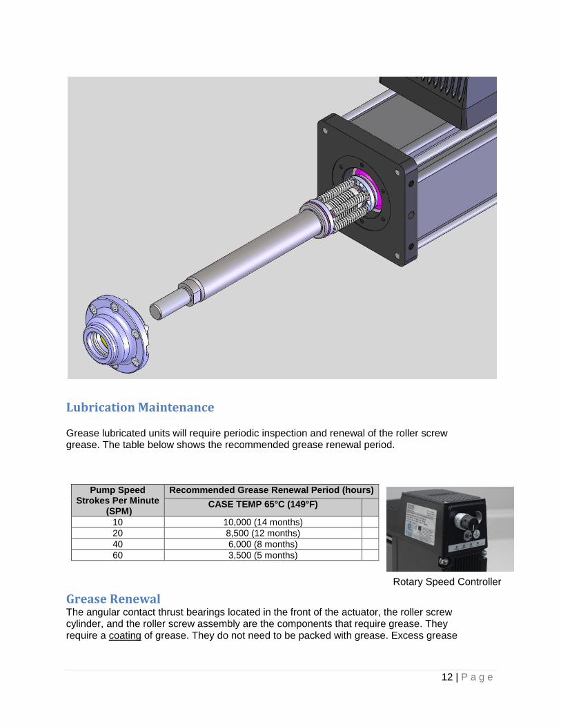
Disassembly Refer to the exploded view on the following page. 1.) Remove the actuator assembly from the machine by disconnecting the cables, main rod coupling clip and actuator mounting bolts on the fluid head yoke. The coupler and anti rotate device can remain attached to the shaft for maintenance of the drive.
The end cap houses the servo drive and control. Extreme care should be taken when removing the tie rod nuts or tie rods so as not to twist or pull on the drive section of the actuator. Do not disconnect the wiring between the drive and the actuator.
2) Remove the screws holding the seal gland to the face plate. With the screws removed, pull the seal gland off. Pry spots are located on each side of the gland to aid in removal.
3.) When the seal gland is removed, the open end of the roller screw internally threaded cylinder (ITC) is visible. The roller screw can be removed by turning it counter clockwise and threading it out of the cylinder. It may be necessary to keep the roller screw cylinder from turning to remove the screw.
CAUTION
12 | P a g e
Lubrication Maintenance Grease lubricated units will require periodic inspection and renewal of the roller screw grease. The table below shows the recommended grease renewal period.
Pump Speed Strokes Per Minute
(SPM)
Recommended Grease Renewal Period (hours)
CASE TEMP 65°C (149°F)
10 10,000 (14 months)
20 8,500 (12 months)
40 6,000 (8 months)
60 3,500 (5 months)
Grease Renewal The angular contact thrust bearings located in the front of the actuator, the roller screw cylinder, and the roller screw assembly are the components that require grease. They require a coating of grease. They do not need to be packed with grease. Excess grease
Rotary Speed Controller

13 | P a g e
requires more torque from the motor when returned to operation, and does not improve the lubrication of the unit. The CVS Controls servo actuators are shipped from the factory fully greased and ready for installation. CVS Controls recommends using Mobilith SHC 220, a high performance, extreme-pressure grease. The unique physical properties of the synthetic base oil provides outstanding protection against wear, rust, corrosion and high or low-temperature degradation. Mobilith SHC allows for very low starting and running torque values. Its operating range is -40 degrees C to 177 degrees C (-40 degrees F to 350 degrees F).
1.) Use a brush to work approximately 0.5 in3 of grease for every 3 inches of stroke length into the roller screw cylinder. Be sure to cover all of the threaded areas of the cylinder. 2.) Use a brush to work grease in to the roller screw assembly. Be sure to cover all the threaded surfaces of the screw assembly. This can be accomplished by applying grease to a few places on the roller screw assembly and rotating the components repeatedly in both directions to work the grease into the assembly.
Reassembly 1.) Rethread the roller screw into the internally threaded cylinder (ITC). It is a multiple start screw, and this is not always easy. DO NOT FORCE THE ROLLER SCREW INTO THE CYLINDER. It is best to have the actuator vertical with the open end of the roller screw cylinder facing up. Position the roller screw above the cylinder so that it is aligned axially with the ITC. Slowly turn the roller screw 1/4 to 1/2 a turn counterclockwise with it in contact with the ITC. This will help to align the threads on the roller screw with the threads in the ITC. Rotate the roller screw clockwise and it should begin to thread into the cylinder. If it does not turn freely, remove it and begin again. When threading the screw into the cylinder, it will roll freely into the actuator. When it reaches the portion of the cylinder that contains the motor magnets, the roller screw will be more difficult to turn because of the magnetic field of the magnets. THIS IS NORMAL. Continue to thread the roller screw into the cylinder. When it reaches the bottom, it will become difficult to turn and the motor and bearings will begin to rotate with it. The roller screw is now fully inserted into the cylinder. 2.) Place a small amount of seal lubricant on the inside surface of the seal/bushing assembly. 3.) Carefully slide the bushing/seal assembly over the actuator rod end. The seal is a tight fit on the rod end. Take care not to damage the seal on the threads of the extending rod. Standard T2M Series rods have a chamfer to provide a lead in for replacement of the seal and bushing. The mounting screws should have a low or medium strength thread locker added, such as Loctite 222MS. The mounting screws torque values are 27 in-lbs (2.25 lbf-ft, 3.05 N-m) 4.) Ensure the rod has been threaded all the way to the end. Reinstall the yoke and fluid head assembly. Slide the plunger into the coupler and insert the retaining clip.

14 | P a g e
Dimensions: CVS ECP-AC (Inches)
0
25
50
75
100
125
150
175
200
225
250
275
300
0 5 10 15 20 25 30 35 40 45 50 55 60
Vo
lum
e P
um
pe
d L
itre
s p
er
Day
Pump Rate Strokes per Minute (1" Stroke Length)
Electric Chemical Pump Volume Chart
1/4" Plunger
3/8" Plunger
1/2" Plunger

15 | P a g e
CVS Electric Chemical Pump- Injection Head Assembly
Material Pressure, PSIG
1/4" 3/8" 1/2"
Buna-N 1500 1500 1500
Hard 6000 6000 3500
Viton 3500 3500 3500
Teflon 1500 1500 1500
Flouro 1500 1500 1500
Pump Model Numbers CVS Electric Chemical Pump – AC/DC
Item Description Material Ductile
w/SST Trim All SST Trim
Ductile
w/SST Trim All SST Trim
Ductile
w/SST Trim All SST Trim
HEAD ASSY. NO. CVS-LE-0166 CVS-LE-0755 CVS-LE-0203 CVS-LE-0756 CVS-LE-0496 CVS-LE-0732
1 Body CVS-C-0275 CVS-C-0291 CVS-C-0276 CVS-C-0425 CVS-C-0272 CVS-C-0349
2*
Plunger 17-4PH CVS-A-6269 CVS-A-6269 CVS-A-6270 CVS-A-6270 CVS-A-6271 CVS-A-6271
Plunger, Cryo-Treated CVS-A-
1745/CT
CVS-A-
1745/CT
3 Plunger Packing
Gland 303 SST CVS-A-1463 CVS-A-1463 CVS-A-0957 CVS-A-0957 CVS-A-1219 CVS-A-1219
4*
Plunger Packing**
(See table below for
max. discharge press.)
Buna-N
Hard
Viton
Teflon
Flourosilicone
CVS-A-1461
CVS-A-2295
CVS-A-4102
CVS-A-1642
CVS-A-1461/FS
CVS-A-1461
CVS-A-2295
CVS-A-4102
CVS-A-1642
CVS-A-1461/FS
CVS-A-1456
CVS-A-1875
CVS-A-4101
CVS-A-1234
CVS-A-1456/FS
CVS-A-1456
CVS-A-1875
CVS-A-4101
CVS-A-1234
CVS-A-1456/FS
CVS-A-0959
CVS-A-1874
CVS-A-4103
CVS-A-1012
CVS-A-0959/FS
CVS-A-0959
CVS-A-1874
CVS-A-4103
CVS-A-1012
CVS-A-0959/FS
5*
O-Ring, Suction &
discharge (included in
items 9 & 14)
Buna-N
Viton
Flourosilicone
CVS-A-0479
CVS-A-2580
CVS-A-0479/FS
CVS-A-0479
CVS-A-2580
CVS-A-0479/FS
CVS-A-0479
CVS-A-2580
CVS-A-0479/FS
CVS-A-0479
CVS-A-2580
CVS-A-0479/FS
CVS-A-0479
CVS-A-2580
CVS-A-0479/FS
CVS-A-0479
CVS-A-2580
CVS-A-0479/FS
6 Top Bushing 302 SST CVS-A-1496 CVS-A-1496 CVS-A-1496 CVS-A-1496 CVS-A-1496 CVS-A-1496
7* Spring 316 SST CVS-A-0077 CVS-A-0077 CVS-A-0077 CVS-A-0077 CVS-A-0077 CVS-A-0077
8* 3/8” SST Ball 316 SST CVS-A-0054 CVS-A-0054 CVS-A-0054 CVS-A-0054 CVS-A-0054 CVS-A-0054
9*
Top Seat Assembly
303 SST
CVS-B-0737 CVS-B-0737 CVS-B-0737 CVS-B-0737 CVS-B-0737 CVS-B-0737
Top Seat Assembly
(Metal to Metal) CVS-A-0806 CVS-A-0806 CVS-A-0806 CVS-A-0806 CVS-A-0806 CVS-A-0806
10* 1/4” SST Ball 316 SST CVS-A-0126 CVS-A-0126 CVS-A-0126 CVS-A-0126 CVS-A-0126 CVS-A-0126
11 Priming Valve 303 SST CVS-A-1497 CVS-A-1497 CVS-A-1497 CVS-A-1497 CVS-A-1497 CVS-A-1497
12 Plunger Pkg. Gland
Nut 303 SST CVS-A-4104 CVS-A-4104 CVS-A-4104 CVS-A-4104 CVS-A-4104 CVS-A-4104
13*
Suction Ball - 3/8”
316 SST
CVS-A-0054 CVS-A-0054 CVS-A-0054 CVS-A-0054 CVS-A-0054 CVS-A-0054
Suction Ball - 1/2”
(use with CVS-A-0771
metal to metal bottom
seat only)
CVS-A-0053 CVS-A-0053 CVS-A-0053 CVS-A-0053 CVS-A-0053 CVS-A-0053
14*
Bottom Seat
303 SST
CVS-B-0736 CVS-B-0736 CVS-B-0736 CVS-B-0736 CVS-B-0736 CVS-B-0736
Bottom Seat
Metal to Metal
(use with CVS-A-0053
1/2” ball only)
CVS-A-0771 CVS-A-0771 CVS-A-0771 CVS-A-0771 CVS-A-0771 CVS-A-0771
15 Locknut Brass CVS-A-0225 CVS-A-0225 CVS-A-0225 CVS-A-0225 CVS-A-0225 CVS-A-0225
PACKING SET
STACK HEIGHTS
1/4" , 3/8", 1/2" HEADS

16 | P a g e
Head Office 3900 101 Street Edmonton, Alberta T6E 0A5 Canada Office: (780) 437-3055 Fax: (780) 436-5461
Calgary Sales Office 3516 114 Avenue SE Calgary, Alberta T2E 6Z3 Canada Office: (403) 250-1416 Fax: (403) 291-9487
Website: www.cvs-controls.com Email: [email protected]
July 2019