cutting tool technology - · pdf filethis review is organized into the following sections: 1)...
TRANSCRIPT
AMT Certification Program - Study Guide
September 2013 (S.G. 09.13) Page 1 (Cutting Tool Technology) Chapter 9
CHAPTER
CUTTING TOOL TECHNOLOGY
9.1 Introduction 9.2 Glossary 9.3 Workpiece Materials 9.4 Cutting Tool Materials 9.5 Principals of Machining 9.6 Basic Machining Processes 9.7 Workholding Considerations 9.8 Special Applications & Part Runoffs 9.9 CNC Tool Management 9.10 Abrasive Tools & Machining 9.11 Non-Traditional Machining 9.12 Review Questions
9.1 Introduction This review is organized into the following sections: 1) Workpiece Materials, 2) Cutting Tool Materials, 3) Principles of Machining, 4) Special Applications and Part Runoffs, 5) Basic Machining Process, 6) NC Tool Management, 7) Abrasive Tools and Machining and 8) Non-Traditional Machining. It is intended to be a brief overview of each area. Additional independent study in each area is recommended to prepare properly for the certification exam.
9
AMT Certification Program - Study Guide
September 2013 (S.G. 09.13) Page 2 (Cutting Tool Technology) Chapter 9
9.2 Glossary
Annealing - A heat treatment process to reduce hardness or brittleness, relieve stresses, improve machinability, facilitate cold working, or produce a desired microstructure or properties. The process consists of heating to a suitable temperature, which is dependent upon the type of annealing, followed by slow cooling.
Alloy - A metal containing additions of other metallic or non-metallic elements to enhance specific properties such as strength and corrosion resistance.
Boring - A precision machining process for generating internal cylindrical forms by removing metal with single point or multiple-edge tools. The process is most often used with the workpiece held stationery with a rotating cutting tool.
Bond - The material that holds the abrasive grain in place in the form of a grinding wheel.
Brittleness - The quality of a material that leads to fracture without appreciable plastic deformation. Brittleness is the opposite of plasticity.
Broach - A multi-tooth, bar-like cutting tool; the teeth are shaped to give a desired surface or contour, and cutting results from each tooth projecting farther than the preceding one.
Broaching - A metal removal technique for internal or external machining of flat, round or contoured surfaces using a multi-tooth cutting tool that is pushed or pulled in relation to the workpiece being machined. Each tooth on the cutting tool (broach) is generally higher than the preceding tooth and as a result the depth of cut increases as the operation progresses.
Burnishing - The very heavy rubbing of two surfaces, where one is much harder than the other. The result being that the softer surface has been flattened and its surface finish altered. Normally utilized in high production finishing operations (i.e., hole finishing via roller burnishing).
Case hardening - A process of surface hardening involving a change in the composition of the outer layer of an iron base alloy followed by appropriate thermal treatment. Typical case hardening processes are 1) carburizing, 2) cyaniding, 3) carbonitriding and 4) nitriding.
Cast iron - A generic term for a large group of cast ferrous alloys containing over 2% carbon and 1% silicone.
Cast steel - Steel in the form of castings, characterized by a grain structure produced by solidification. Two general groups are carbon steel and alloy steel. Carbon steel castings contain carbon, manganese, silicon, phosphorus and sulfur. Alloy steel castings contain alloying elements such as manganese, chromium, nickel, molybdenum, vanadium.

AMT Certification Program - Study Guide
September 2013 (S.G. 09.13) Page 3 (Cutting Tool Technology) Chapter 9
Ceramic tool - A cutting tool tip made from metallic oxides. These tips are normally supplied as indexable inserts.
Chip Control - The chip removal process creates chips or excess removed material that can interfere with the machining process either during the actual cutting procedure or by the excess of chips in and around the machine tool. Thus chip control is the direction of chips into areas where there is no interference with or influence on the machining process.
Chip Removal - Relates to the machining process of producing a part piece by removing unwanted material on interior or exterior surfaces. The workpiece is the end result of chip removal.
Cutoff tool - A tool used on bar-feed type lathes to separate the finished piece from the bar stock.
Depth of cut - The distance into the workpiece material that the tool cuts on each pass. Dressing - A conditioning process performed on an abrasive grinding wheel to remove unwanted material and expose new, sharp abrasive grain.
Drilling - The production or enlarging of holes by rotary relative motion of the workpiece and a sharpened tool known as a drill bit. The cutting tool, the workpiece, or both may rotate, with the tool generally being fed along its long axis.
Ductility - The ability of a metal to undergo substantial amounts of plastic deformation before fracture. It can also be described as the plasticity shown by a metal under pulling, or tensional load.
Face (of a cutting tool) - The surface, against which the chips bear, as they are severed in turning or planing operations, is called the face.
Face milling - Milling flat surfaces perpendicular to the rotational axes of the milling cutter or cutting tool.
Feedrate - The speed of relative motion between the tool and workpiece in the main direction of cutting.
Fixture - A device used to hold a part such that its reference axes are in a defined orientation with respect to the reference axes of a tool.
Flank - The flank is that end surface adjacent to the cutting edge and below it when the tool is in a horizontal position as for turning.
Free machining - A term used to describe metals having alloying additions, such as lead, manganese, or sulfur, that reduce the tool force required in machining operations.
Friability - This term refers to the ability of the abrasive (e.g., grinding wheel) to fracture.
AMT Certification Program - Study Guide
September 2013 (S.G. 09.13) Page 4 (Cutting Tool Technology) Chapter 9
Grain size - This refers to a number, which corresponds to the mesh size used for sizing the abrasive grain. The mesh number refers to the fraction of an inch that the wire mesh is spaced for sizing the abrasive grain.
Grain - An individual crystal in a metal or alloy.
Grinding - Removing material from a workpiece with a grinding wheel or coated abrasives.
Group technology - A method by which classification and coding schemes are used to identify and aggregate related part numbers so that design and manufacturing efforts can take advantage of their similarities.
Hard Turning - An extension of the single point tool turning or lathe process of machining that embodies the use of very hard cutting tools taking light depths of cut on hardened steel workpieces. Hard turning can be considered somewhat competitive to grinding and the process requires rigid machine tools, well-prepared cutting tools and accurate servo drive systems.
Hardening - Any process of increasing hardness of metal by suitable treatment, usually involving heating and cooling.
Hardness - The ability of a metal to withstand indentation or penetration. Two primary methods are used to determine hardness - Brinell and Rockwell.
High Speed Machining - A machining process usually, but not always associated with milling, that incorporates spindle RPM’s and feed rates well beyond those used with normal milling and is used in machining nonferrous materials. High speed machining is also discussed in Chapter 10, Machine Tool Design.
Honing - An abrasive process usually performed on internal cylindrical surfaces, which employs bonded abrasive stones in a special holder to remove stock and improve surface finish.
Laser assisted machining - The use of a laser beam to heat and soften a metal workpiece just ahead of a cutting tool to make the workpiece easier to machine.
Lead - When a threaded part is rotated about its axis with respect to a fixed mating thread, the lead is the axial distance moved by the part in relation to the amount of angular rotation. The basic lead is commonly specified as the distance to be moved in one complete rotation. It is necessary to distinguish lead from measurements of pitch as uniformity of pitch measurements does not ensure uniformity of lead.
Lot size - A quantity of items or workpieces to be produced at a given time.
Machinability - The relative ease with which materials can be shaped by cutting, drilling, or other chip-forming processes.
Malleability - The ability of a metal to be flattened, hammered, or rolled without fracture. It can also be described as the plasticity shown by a metal under a compressive load.
AMT Certification Program - Study Guide
September 2013 (S.G. 09.13) Page 5 (Cutting Tool Technology) Chapter 9
Milling - A machining process that removes material from a workpiece by relative motion between a workpiece and a rotating cutter having multiple cutting edges.
Normalizing - A process in which an iron-base alloy is heated to a temperature above the transformation range and subsequently cooled in still air at room temperature.
Pallet - Device which serves as a standardized conveyance for the part.
Pitch - The pitch of a thread having uniform spacing is the distance, measured parallel to its axis, between corresponding points on adjacent thread form plane and on the same side of the axis. Pitch is equal to lead divided by the number of thread starts.
Pitch diameter - On a straight thread the thread diameter is the diameter of the pitch cylinder. On a taper thread, the pitch diameter at a given position on the thread axis is the diameter of the pitch cone at that position.
Plasticity - The ability of a metal to be extensively deformed without fracture or rupture.
Quenching - Quick cooling after a heat-treating process.
Rake angle - A metal cutting tool is said to have rake when the tool face or surface against which the chips bear as they are being severed, is inclined for the purpose of either increasing or diminishing the keenness or bluntness of the edge. The magnitude of the rake is most conveniently measured by two angles called the back rake and the side rake angle.
Positive rake - The orientation of a cutting tool whose cutting edge leads the surface of the face. Negative rake - The orientation of a cutting tool whose cutting edge lags the surface of the face.
Reaming - Reaming is a machining function using rotary, fluted cutting tools (reamers) to enlarge, smooth or finish size holes - normally, a secondary operation after drilling. The finish hole size is determined by the diameter of the reamer. Light chip loads and high rigidity are basic needs in this machining operation.
Relief angle - The angle between a relieved surface and a tangential plane at a cutting edge. Nose relief - The relief angle under the nose radius or tip.
Setup - Entity consisting of one or more parts mounted in specific orientation(s) on a single fixture.
Spark-out - A grinding term, which refers to the condition at the end of a grind cycle when machining forces are minimized and there is no further feed.
Stock - Workpiece material to be removed.
Strength - A property of metal that allows it to resist permanent change in shape when loads are applied. The four types of strength are 1) tensile, 2) shear, 3) compressive and 4) ultimate.

AMT Certification Program - Study Guide
September 2013 (S.G. 09.13) Page 6 (Cutting Tool Technology) Chapter 9
Stress relieving - A process to relieve internal residual stresses in a metal object by heating the object to a suitable temperature and holding for a proper time at that temperature. This process may be applied to relieve stresses induced by casting, quenching, normalizing, machining, cold working or welding.
Surface hardening - A heating, cooling or surface penetration method to provide a surface that is harder than the internal sections of the metal.
Tapping - Forming an internal screw thread in a hole or other part by means of a tap.
Tempering - Reheating of previously heated, hardened or normalized material for the purpose of decreasing the hardness, minimizing stresses, improving ductility, and increasing toughness.
Tensile strength - The ability of a metal to resist being pulled apart by opposing forces acting in a straight line.
Threading - Any of several processes used to produce standard spiral grooves on a cylindrical internal or external surface. Turning, boring, milling, grinding, or rolling may produce threads.
Thread rolling (thread forming) - A simple cold forging process for producing threads on cylindrical or conical workpieces by displacing material rather than by removing material as in thread cutting or thread grinding.
Toughness - The ability of a metal to resist, or absorb, sudden shocks or loads without breaking.
Turning - A machining process in which a workpiece is held and rotated against a single point tool to form flat or contoured surfaces concentric with the longitudinal axis of the workpiece.
Truing - A shaping process performed on an abrasive wheel to restore shape, roundness and concentricity.
Vitrified - This is a bonding system (for grinding wheels) which is very brittle and is achieved by firing a mixture of abrasive and feldspar or silica in a kiln like a piece of pottery.
Wear resistance - The ability of a metal to resist abrasion. In most cases, the harder the metal, the better it resists wear.

AMT Certification Program - Study Guide
September 2013 (S.G. 09.13) Page 7 (Cutting Tool Technology) Chapter 9
9.3 Workpiece Materials
MATERIAL PROPERTIES Workpiece materials are selected based primarily on the end use of the workpiece. The characteristics of a material are called its properties. They fall into 3 categories:
1. Chemical properties (e.g., oxidation & interaction with other materials), 2. Physical properties (e.g., thermal [melting temp & thermal expansion], electrical
& magnetic) and, 3. Mechanical properties (e.g. hardness, strength, elasticity & coefficient of
friction).
This study guide will be confined to information regarding metals since they are the most common materials found in workpieces. Metals can be placed into two groups: 1) ferrous and 2) non-ferrous. Here are some common metals ranked by group:
Ferrous Non-Ferrous Iron Aluminum Steel Magnesium Steel Alloys: Copper
Nickel steel Non Ferrous Alloys: Vanadium steel Brass Tungsten steel Bronze Others Monel
Normally, the mechanical properties are of primary consideration for the application of the workpiece. However, all three areas can become considerations in determining the machi-nability of the workpiece. The best situation is where material properties for both 1) work-piece application and 2) workpiece machinability have been optimized. Machinability will be discussed in more detail later.
MATERIAL CLASSIFICATIONS Advances in material science have made available new materials to the product designer. Workpiece metals can include cast irons, steels (carbon, alloy, tool, stainless, cast, etc.), aluminum, copper, cooper-tin alloys (bronzes), copper-zinc alloys (brasses), magnesium, titanium, high-temperature alloys (include Inconel and cobalt), and many other combina-tions. Standard material classification systems exist for some of these materials such as carbon steels, alloy steels, stainless steels, aluminum and magnesium in order to make specifying materials easier. The more exotic materials may use a description along with a

AMT Certification Program - Study Guide
September 2013 (S.G. 09.13) Page 8 (Cutting Tool Technology) Chapter 9
Brinell hardness (BHN) or tensile strength rating to determine identification. Consideration in this study guide will be limited to the more common metals.
Carbon and Alloy Steels The SAE (Society of Automotive Engineers) and AISI (American Iron and Steel Insti-tute) maintain an almost identical numbering scheme for the carbon and alloy steels. The numbering system is based on the chemical composition of the material. The numbering system defines the: 1) types and amount of alloying element in the steel and, 2) percentage of carbon in the steel. An alloy is defined as "a metal containing additions of other metallic or non-metallic elements to enhance specific properties such as strength and corrosion resistance." The first two digits define the common alloys found in steels, which are carbon, nickel, manganese, molybdenum and chromium. The last two digits indicate the percentage of carbon in the steel in tenths and hundredths of one percent.
SAE/AISI First 2 Digits
Common Alloying Elements
10 Plain Carbon 11,12 Carbon w/sulfur & phosphorous 13 Manganese 23, 25 Nickel 31, 32, 33, 34 Nickel-Chromium 40, 44 Molybdenum Steel 50, 51, 52 Chromium Steel 61 Chromium-Vanadium Steel
The production method used in the manufacture of steels and alloys falls into three categories: 1) cold worked, 2) hot worked, and 3) cast. If a letter precedes the classifi-cation code it refers to the production process used in making the steel.
A - basic open-hearth alloy steel C - basic open-hearth carbon steel B - acid Bessemer carbon steel D - electric furnace steel

AMT Certification Program - Study Guide
September 2013 (S.G. 09.13) Page 9 (Cutting Tool Technology) Chapter 9
Examples of SAE/AISI numbers for steels are as follows:
First two digits (type and amount of alloying element)
Last two or three digits (% of carbon in the steel in tenths and hundredths of one percent)
SAE/AISI 10120
10 plain carbon
120 1.20% of carbon
SAE/AISI 4042
40 molybdenum
42 0.42% of carbon in the steel
Alloying elements are found in varying degrees of content in steel and are referred to as low (max. 5%), medium (5 to 10%) or high (10% or more) alloy. Each alloying element has its own usefulness to the alloy. Here are a few common examples:
Boron: Increases hardenability
Carbon: Increases tensile strength and toughness Decreases ductility
Chromium: Improves depth hardness and wear resistance Resists corrosion
Lead: Reduces cutting friction, improves machinability Manganese Improves hardness and wear resistance
Molybdenum: Improves depth hardness Improved strength at high temperatures
Nickel: Increases tensile strength and toughness Decreases' ductility (better ductility than carbon) Improves machinability
Phosphorus: Reduces toughness Increases formability at high temperatures
Sulfur: Improves machinability Found in 11XX steels which are called "Free-Machining" steels
Tool Steel & Stainless Steel Workpieces can be made of tool steels and stainless steels. These steels are much harder to machine and require special tooling and machining considerations. Tool steels are very tough and extremely tolerant of shock, heat and wear. They contain high levels of carbon, cobalt and tungsten. Stainless steels are another special alloy steel. They contain over 12% chromium, which makes them very hard and resistant to corrosion. Stainless steels have three forms: 1) ferrous, 2) martensitic and 3) austenitic. Stainless steels also have their own classification codes. The machine tool salesman should be familiar with the classification codes of both tool steel and stainless steel and the characteristics of each type. Refer to a machinist handbook for the complete coding system and characteristics.
AMT Certification Program - Study Guide
September 2013 (S.G. 09.13) Page 10 (Cutting Tool Technology) Chapter 9
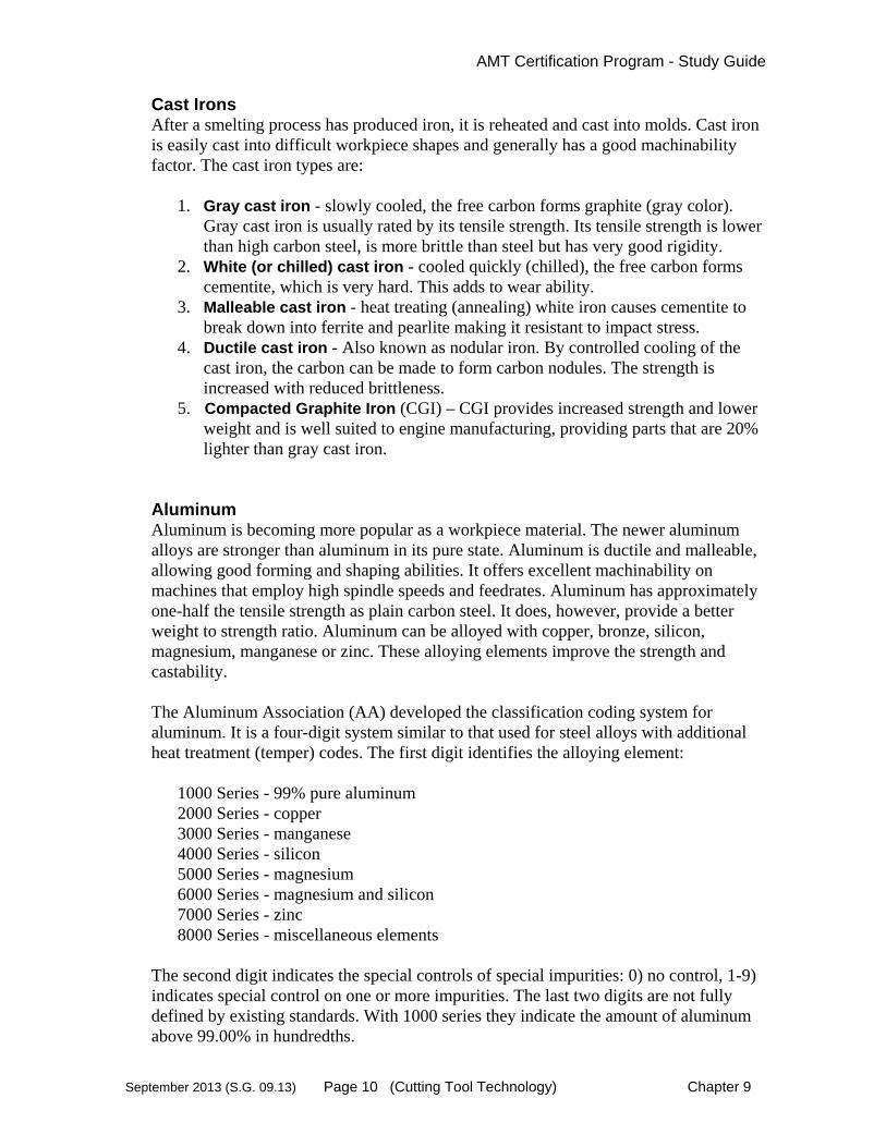
Cast Irons After a smelting process has produced iron, it is reheated and cast into molds. Cast iron is easily cast into difficult workpiece shapes and generally has a good machinability factor. The cast iron types are:
1. Gray cast iron - slowly cooled, the free carbon forms graphite (gray color).
Gray cast iron is usually rated by its tensile strength. Its tensile strength is lower than high carbon steel, is more brittle than steel but has very good rigidity.
2. White (or chilled) cast iron - cooled quickly (chilled), the free carbon forms cementite, which is very hard. This adds to wear ability.
3. Malleable cast iron - heat treating (annealing) white iron causes cementite to break down into ferrite and pearlite making it resistant to impact stress.
4. Ductile cast iron - Also known as nodular iron. By controlled cooling of the cast iron, the carbon can be made to form carbon nodules. The strength is increased with reduced brittleness.
5. Compacted Graphite Iron (CGI) – CGI provides increased strength and lower weight and is well suited to engine manufacturing, providing parts that are 20% lighter than gray cast iron.
Aluminum Aluminum is becoming more popular as a workpiece material. The newer aluminum alloys are stronger than aluminum in its pure state. Aluminum is ductile and malleable, allowing good forming and shaping abilities. It offers excellent machinability on machines that employ high spindle speeds and feedrates. Aluminum has approximately one-half the tensile strength as plain carbon steel. It does, however, provide a better weight to strength ratio. Aluminum can be alloyed with copper, bronze, silicon, magnesium, manganese or zinc. These alloying elements improve the strength and castability. The Aluminum Association (AA) developed the classification coding system for aluminum. It is a four-digit system similar to that used for steel alloys with additional heat treatment (temper) codes. The first digit identifies the alloying element:
1000 Series - 99% pure aluminum 2000 Series - copper 3000 Series - manganese 4000 Series - silicon 5000 Series - magnesium 6000 Series - magnesium and silicon 7000 Series - zinc 8000 Series - miscellaneous elements
The second digit indicates the special controls of special impurities: 0) no control, 1-9) indicates special control on one or more impurities. The last two digits are not fully defined by existing standards. With 1000 series they indicate the amount of aluminum above 99.00% in hundredths.

AMT Certification Program - Study Guide
September 2013 (S.G. 09.13) Page 11 (Cutting Tool Technology) Chapter 9
First digit (Type and amount of alloy)
Second digit (Control of special individual impurities)
Last two digits (The last two digits are not standardized for all designations)
1030 1 - Alum.of 99.00% or greater
0 - No special control of individual impurities
30 - Amount of Alum.above 99.00% in hundredths.
2014 2 - copper alloying element
0 - No special control of individual impurities
14 - Identifies additional alloys
The machine tool sales engineer needs a working knowledge of these numbering systems in order to understand the machine and tooling requirements when analyzing customer's needs and preparing proposals. Heat Resistant Super Alloys (HRSA) and Titanium Increased alloy content (Co more so than Ni), results in better resistance to heat, increased tensile strength and higher corrosive resistance. It can be annealed, solution heat treated, aged, rolled, forged and cast. HRSA materials can be split into three groups:
ickel‐based alloys. ron‐based alloys. Cobalt‐based alloys.
The physical properties and machining behavior of these alloys vary considerably, due to the chemical composition and the precise metallurgical processing it receives during manufacture. Annealing and aging are particularly influential on the machining properties. The cutting forces and power requirements are high.
HEAT TREATMENT Both ferrous and non-ferrous metals can be heat-treated. Heat-treating is used to change the properties of the metal to make it more suitable for its application. The following heat treatment processes can be used on each type of metal group.
Heat Treatment Process
Ferrous Metals (Steels)
Non-Ferrous Metals
Annealing Yes Most Normalizing Yes No

AMT Certification Program - Study Guide
September 2013 (S.G. 09.13) Page 12 (Cutting Tool Technology) Chapter 9
Hardening Yes Some Tempering Yes No Case Hardening Yes No
Each heat treatment process affects a different characteristic in the metal such as:
1. Improve machinability. 5. Increase or decrease malleability. 2. Increase or reduce hardness. 6. Increase or reduce wear resistance. 3. Relieve stresses. 7. Increase or reduce brittleness. 4. Increase or decrease ductility. 8. Increase shock resistance.
The five main heat-treating methods are 1) Annealing, 2) Normalizing, 3) Hardening, 4) Tempering, and 5) Case Hardening. A definition of each process is found in the glossary. The machine tool sales engineer should study the specific effects of each method.
Notes

AMT Certification Program - Study Guide
September 2013 (S.G. 09.13) Page 13 (Cutting Tool Technology) Chapter 9
9.4 Cutting Tool Materials
The development of new cutting tool materials has had a continual and profound impact on manufacturing productivity. New materials have forced machine tool designs to change, plants to change processing methods and new workpiece materials to be considered. The ultimate success of the machining process revolves around the events at the tool point. The characteristics of the tool material are therefore critical. There are five important qualities that cutting tools need to perform their job.
1. Hot hardness - ability to maintain hardness and a sharp edge at high tempera-tures.
2. Resistance to thermal shock - ability to withstand the cyclic heating and cooling produced while cutting.
3. Lack of affinity - ability to resist chemical fusion with the workpiece at high temperatures.
4. Resistance to oxidation - ability to resist the destruction of chemical oxidation at high temperatures.
5. Toughness - ability to withstand the cutting forces and shock loads.
No one tool has all of these qualities. Therefore, each tool must be carefully selected based on the application variables. The most common types of cutting tool materials in use today are:
High-Speed Steel - wrought (HSS) High-Speed Steel - powdered metal (HSS) Cast Alloy (Cobalt-based) Carbides:
Tungsten carbide (WC) Titanium carbide (TiC) Tantalum carbide (TaC)
Coated Carbides:Titanium carbide coating (TiC) Titanium nitride coating (TiN) Hafnium nitride coating (HfN) Aluminum Oxide coating (Al2O3)
Ceramics: Plain ceramics Composite ceramics (Cermets)
Cubic Boron Nitride (CBN) Diamonds:
Single-crystal (natural) Polycrystalline (man-made) (PCD)

AMT Certification Program - Study Guide
September 2013 (S.G. 09.13) Page 14 (Cutting Tool Technology) Chapter 9
APPLICATION CONSIDERATIONS A brief comparison of key material qualities (below) clearly shows that the cutting tool material must be selected based on the cutting situation.
Toughness Hardness Wear Resist. Cut Speed High-Speed steel Carbide (Tungsten) Ceramics Diamonds
There is no exact correlation for combinations of workpiece material, surface speed and tool material. While application charts indicate basic guidelines, the shop provides the final "trial and error" laboratory. Patience is the rule for optimizing the tooling type and grade for any given process. During this process the problems and failures become important signals along the path to increased machinability. A good tooling application guide can recommend specific steps for each symptom. Symptoms include 1) abrasion or flankwear, 2) cratering, 3) chipping, 4) built-up edge (BUE), 5) edge deformation, 6) thermal cracking and, 7) fractures.
High-Speed Steel tooling is used on applications requiring extreme toughness such as severe interrupted cuts and machining of exotic materials. High-speed steels are also useful for formed tools since they are easily ground to shape. As toughness decreases, the tool becomes more brittle and should be used in applications with minimal mechanical shock, such as interrupted cuts. This holds true for many carbides, ceramics, CBN and diamond materials. These tools also require a rigid machine, a solid tool holder and strong setup to achieve optimum results. These harder, less tough, tools are best used in high-speed, high temperature machining and are excellent for finishing. Ceramics generally consist of aluminum oxides mixed with small quantities of metals. Ceramic tools have the advantage of being more chemically inactive than carbides, yielding less affinity with workpiece metals. Diamond products are not well suited for machining steels due to affinity problems. Diamonds work well with copper, aluminum, plastics, graphite and concrete. Carbide tools are formed by compressing carbide aggregate (small pieces) and powdered cobalt. It is then subjected to a high heat sintering process, which melts the cobalt. The cobalt becomes the bonding agent. The carbide tip or insert must be held in a holder. Some tips and inserts are brazed or welded into a holder while others are held mechanically. Inserts and tips are normally ground to produce a consistent and sharp edge. In many cases, a honed edge at the junction of the top face and side face is used to provide a consistent cutting edge that resists chipping and fracturing. The common term is to provide a small consistent predetermined "wear land". Changing the amount of carbide aggregate and cobalt change the cutting characteristics of the tool. Inserts can be found in a variety of shapes that include round, square, parallelogram, triangle, pentagon, hexagon, octagon and
AMT Certification Program - Study Guide
September 2013 (S.G. 09.13) Page 15 (Cutting Tool Technology) Chapter 9
custom shapes. The round and square inserts are the strongest. Inserts can have single or multiple cutting faces and some can be flipped over to provide additional cutting faces on the other side. Coated Carbide inserts are a popular way to increase tooling performance. Coatings are usually Titanium carbide, Tungsten carbide, Hafnium nitride or Aluminum oxide. Coatings are applied by several methods to achieve different thickness and characteristics (sometimes multiple layers are applied). Coatings can add strength, stability and lubricity, improve wear, and lessen affinity. New technologies in cutting tools include advances in four areas. These are 1) control of microstructure, 2) development of more composites, 3) improved coatings and, 4) improved superhard materials. Already, new coatings for carbide inserts as well as whisker technology, using thin slivers of glass material, promise increased application opportunities and productivity.
Classification System Both US and ISO international classifications exist for carbides. As manufacturing becomes more global the ISO designation may appear on customer specifications. The US C-System is based on a nomenclature that ranges from C-1 to C-8. The ISO standard uses P, M, and K ranges to classify carbides. High-speed steels are classified by M or T code ranges. The M code indicates a molybdenum additive; the T code indicates a tungsten additive. Refer to charts found in machining handbooks or carbide manufacturer's manuals to gain familiarity to the codes and applications for carbides and high-speed steel. Toolholders So far our discussion has only concerned the tool insert. Critical to the success of the tool is the holder that carries, supports and possibly stores the tool insert. The tool holder, by nature, adds one or more joints between the tool tip and the machine, making rigidity the key factor, especially with carbides, ceramics and superhard inserts. Any number of designs can retain tips and inserts: 1) brazing or welding, 2) pin lock, 3) clamp lock or some combination. The mounting surface must accommodate the shape of the insert and may also affect tool geometry such as additional rake angle. Tool holders differ significantly between turning, milling, drilling and boring applications. Turning uses a stationary tool holder while in milling, drilling and boring the tool rotates. Tool holders may be of the integral type - connecting directly to the machine spindle, cross-slide or turret or they may be part of a modular tooling system that allows different tool modules to be interchanged with each other.
Modular Tooling Systems (MTS) are very popular on lathes and gaining popularity on other machines. Automatic tool changers on CNC machines have increased the use of modular-type quick-change tooling. The toolholder assembly must be held in the spindle or cross-slide in a rigid fashion. Typically, both straight-shank and taper flange attachment systems have been popular depending upon the machine and application. Tool holders have a classification coding system, which defines the insert pocket, holding mechanism and body design. Milling cutter bodies are identified by a code that specifies 1) vendor, 2) style or rake angle, 3) hand, 4)

AMT Certification Program - Study Guide
September 2013 (S.G. 09.13) Page 16 (Cutting Tool Technology) Chapter 9
diameter, 5) insert style, 6) clearance, 7) insert IC, 8) lead angle and, 9) pitch. Other industry standards apply to tool holders in areas such as taper shank design. Additional information on toolholders can be found in the “Basic Machining Processes” chapter.
Machining Center Standard Toolholders - The connection of cutting tool holders to the spindle of a machining center or dedicated milling or boring machine tool is generally done with a tapered shank type toolholder. The steepness of the taper and size of the tool holder at the gauge line (the major diameter) identify the toolholder. Industry standards prevail in defining the exact taper configuration. Two standard American tapers are the BT and CAT shank toolholders. European and Japanese Standards are also available. Tapers sizes have been 20, 30, 40, 45, 50 and the rarely used #60. Refer to Figure 1. These tapered toolholders require a matching taper in the spindle of the machine tool and as the taper size increases so does the weight and cost. Each taper size has standard dimensions for manufacturing and quality identification purposes. A new proprietary toolholder called the “Big-Plus” will fit in BT spindles, but locates on both the taper and spindle bar face. This allows additional rigidity and higher rotational speeds. Machining Center HSK Spindles and Toolholders - The fit between the toolholder and the machine tool spindle is critical in the performance of the machining process and the inexact fit of a toolholder will, in certain cases, limit the production rates and quality of a workpiece. German automotive manufacturers seeking increased metal removal rates in milling and drilling operations developed a new tool holder taper called “HSK” which replaces, when desired, the standard tapers described above. HSK toolholders and tool shanks are not as steep nor is the toolholder as large as a comparable #30, 40 or 50-tapered tool holders. Locking of the toolholder in the spindle tends to slightly deform the toolholder, thus insuring a stronger metal-to-metal fit. The toolholder, when locked, rests against the spindle face with no clearance. This in turn provides higher rigidity, greater metal removal ability and improved accuracy in the machining process. HSK spindles and toolholders are generally more expensive due to the high precision and lower usage. The grinding of the OD of the toolholder and the ID of the spindle requires special gauges, inspection procedures and a tightly controlled manufacturing process. Coromant Capto – Features a 1/20 tapered tri-polygon connection, providing simultaneous taper and spindle face contact with the elastic deformation of the hollow tapered shank, similar to HSK and KM systems. It provides self-centering and alignment with a high torque stiffness due to the tri-polygon shape. The Capto shank has an 8% smaller diameter but a 20% longer shank than the HSK system. The tri-polygon shape eliminates the need for drive keys, balls and wedges,
RetentionKnob
TaperShank V Flange
Drill
Collet Nose
Fig. 1 – Machining Center Tool Holder
(Courtesy Decision Technology)

AMT Certification Program - Study Guide
September 2013 (S.G. 09.13) Page 17 (Cutting Tool Technology) Chapter 9
minimizing balancing issues. The radial and axial accuracy and repeatability are equivalent to the HSK and KM systems.
Additional Recommendations A machine tool sales engineer can do several things to help himself in the area of tooling.
First, if your distributorship or machine tool suppliers have an applications department, make sure that you use this resource. Establish good working relationships with these application engineers. Second, contact a good full-product tooling salesman who can be available for advice. Third, have several tooling catalogs for reference when the need arises. Fourth, subscribe to at least one tooling magazine to remain up-to-date about termi-nology and new tooling applications.
NOTES

AMT Certification Program - Study Guide
September 2013 (S.G. 09.13) Page 18 (Cutting Tool Technology) Chapter 9
9.5 Principals of Machining
The principles of machining are based on applying a tool to a workpiece, to remove the unwanted material (producing chips) and leaving a finished part. Each workpiece must be processed, which includes logical step-by-step instructions for holding, handling, machin-ing and inspection. This is a complex process involving the interaction of many variables. Common machining operations include, turning, drilling, tapping, milling, boring and grinding. This section will address the general principles of machining.
PROCESSING Processing a workpiece involves the design of the sequential operations performed by one or more machine tools to transform the workpiece from raw material to a finished component. A process engineer, tooling engineer, application engineer or programmer, performs this function. Most customers will have employees that support this manufacturing function. However, there are cases when the customer will request that the machine supplier provide a part process and time study for a specific workpiece, or family of workpieces, as part of their solution or proposal. In these cases, workpiece drawings should be obtained and forwarded to the application-engineering group (distributor or machine manufacturer). The successful vendor may be the one who best processes the workpiece and demonstrates a significant benefit to the customer regarding quality, productivity and the final economic justification. The art of manufacturing and machine-level processing is seldom taught in schools. In most cases it is an acquired skill (tribal knowledge) and depends on experience and creativity. For this reason, the processing solutions received by the customer from various vendors can vary widely in both processing steps and required processing time. A common question is “Where to start?” when it comes to part processing. Experienced process engineers study the part print and observe how the workpiece is dimensioned. Generally, most of the dimensions will be based from one or two workpiece faces or features. This initial clue will dictate that these “base” surfaces or features be machined first so that all other machined
Fig. 2 – Part Processing
(Courtesy Romi Machine Tools)

AMT Certification Program - Study Guide
September 2013 (S.G. 09.13) Page 19 (Cutting Tool Technology) Chapter 9
dimensions can be held to this known or qualified surface. It is similar to a building, where all the dimensions refer back to the foundation. After the base surface(s) or feature(s) have been machined, focus is then directed to “How and where will the part be held (fixtured) so as to reduce the number of setups and machine as many surfaces as possible in the shortest cycle time?” Roughing operations will precede finishing operations and the metal removal rates will be balanced so as to minimize part distortion during production. Application engineers must be able to plan which operations should be done first, second, third and so forth. It is obvious that a hole must be drilled before it is bored, however, the boring may be scheduled after all milling is complete to prevent part distortion due to milling heat or cutting forces. Reducing the number of setups also has a major effect on cycle time and quality. It is not uncommon that processing details will be changed once the workpiece goes into production. Minimal processing may only require calculating a cycle time to machine the workpiece. Additional processing will include 1) detailed consideration of the workpiece material and unmachined or "rough" part conditions, 2) analysis of tolerance requirements, 3) required fixturing and tooling, 4) part orientation in initial and subsequent set-ups, 5) type of machining operations, 6) estimated feeds, speeds and depths of cut per operation and, 7) part runoff, inspection and SPC considerations. Good processing details will increase a customer's confidence in the proposal. The sales engineer should review the proposed process with the application engineer to gain a basic understanding of the process design because it can be an integral part of selling a solution, not just a machine. Customers are impressed when sales engineers are able to relate the proposed process to their manufacturing needs. The sales engineer should be familiar with the processing analysis. Process Time Study #1 The following time study and processing example is for a simple turned workpiece. The entire workpiece will be completed on a 3-axis CNC lathe. Study the drawing and the process time study to understand each process step.
1-5/8 NOM. DIA.
2164
+.015- .000
38
+.015- .000
58
+.010- .000
notch must be centeredon bushing I.D. within.005 T.I.R.
Note: 2164
DIA.1.0101.013
Saw and sand finishacceptable
Fig. 3 – Process Time Study #1- Part Print
(Courtesy Ellison Technologies)
AMT Certification Program - Study Guide
September 2013 (S.G. 09.13) Page 20 (Cutting Tool Technology) Chapter 9
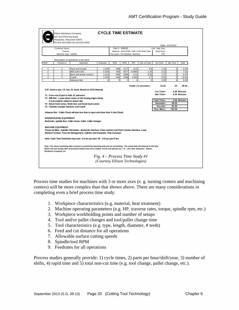
Process time studies for machines with 3 or more axes (e. g. turning centers and machining centers) will be more complex than that shown above. There are many considerations in completing even a brief process time study.
1. Workpiece characteristics (e.g. material, heat treatment) 2. Machine operating parameters (e.g. HP, traverse rates, torque, spindle rpm, etc.) 3. Workpiece workholding points and number of setups 4. Tool and/or pallet changes and tool/pallet change time 5. Tool characteristics (e.g. type, length, diameter, # teeth) 6. Feed and cut distance for all operations 7. Allowable surface cutting speeds 8. Spindle/tool RPM 9. Feedrates for all operations
Process studies generally provide: 1) cycle times, 2) parts per hour/shift/year, 3) number of shifts, 4) rapid time and 5) total non-cut time (e.g. tool change, pallet change, etc.).
Ellison Machinery Company CYCLE TIME ESTIMATEN27 W23750 Paul RoadPewaukee, Wisconsin 53072Ph:414-523-3400 Fax:414-523-3433
Date: 10/15/2002
Customer Name: Part #: 856632 CNC. Mfg. Eng.:
Contact: Material: 1018 DOM 1-5/8 x 5/16 Wall Tube Sales Eng.:
Machine Type: LB35M Part name: Pin Retainer Bushing File:
Description of operations to be done:Tool# Process # Operation Diameter SFM RPM IPR Dist. to Feed Cut Time Idle Time Total
1 1 Face end of part. 1.625 900 2117 0.01 0.5 1.42 3 4.422 2 Mill 21/64 Slot 0.334 400 4577 0.0065 1.25 2.52 5 7.523 3 Bore and break corners 1.012 900 3399 0.01 0.83 1.47 5 6.474 4 Cutoff 1.625 450 1058 0.004 0.7 9.92 5 14.92 Advance Bar 0 0 0 0 0 0.00 6 6.00
Totals ( in seconds ) 15.33 24 39.33
Cut Time= 0.26 MinutesIdle Time= 0.40 Minutes
Total Time= 0.66 Minutes
Seconds= 39.33 Pcs /Hr= 91.54
Pcs / 8hrs= 732.35
O.D. stock is size, I.D. has .01 stock. Based on 1018 Material.
T1 - Face end of part to hold .01 tolerance.T2 - Mill Slot - 1 pass down center of slot leaving edges sharp. A tool could be added to deburr slot.T3 - Break front corner, finish bore and break back corner.T4 - Chamfer Outside Diameter and Cutoff.
Advance Bar - Collet Chuck will take less time to open and close than 3-Jaw Chuck.
WORKHOLDING EQUIPMENT:Barfeeder, spindle liner, Collet chuck, Collet, Collet changer.
MACHINE EQUIPMENT:Chuck Air Blow , Spindle Orientation, Barfeeder interface, Parts Catcher and Parts Catcher interface, Load Monitor Function, Tool Life Management, Cylinder and Drawtube, Chip Conveyor.
Note: Cycle Time Reduction may save 3-6 sec per part. 60 - 132 pcs per 8 hrs.
Note: The above machining data is based on preliminary planning only and are not binding. The actual data will depend on the final fixture and tool design after all technical details have been settled. Feeds and speeds are + or - 10% time allowance. Ellison Machinery Company, Inc.
Fig. 4 – Process Time Study #1 (Courtesy Ellison Technologies)

AMT Certification Program - Study Guide
September 2013 (S.G. 09.13) Page 21 (Cutting Tool Technology) Chapter 9
THE MACHINE TOOL The machine tool provides 1) support and rigidity for the workpiece, 2) rigidity for the tool, 3) force to move the tool and workpiece and, 4) directional control for the cutting process. Major considerations in the machining process are 1) rigidity, 2) spindle horsepower, 3) spindle RPM, 4) end thrust capabilities and, 5) spindle nose, tool and workpiece clearances.
CHIP FORMATION The formation of the chip is at the heart of the metalcutting process. As the tool moves into and across the workpiece it appears that it cuts or slices the chip away from the part. Actually, the tool pushes the metal in front of the tip causing a build up of forces along a shear plane. The workpiece material compression causes deformation along the shear plane and eventually fractures or "slips" up in stacked sheets like a "deck of cards" forming the chip (reference illustration). The chip is not the only metal that is deformed. Since the deformation radiates in all directions from the tool tip the surface left on the workpiece is also affected. Therefore, both the chip and the remaining workpiece surface (surface finish) are formed at the same time. The friction caused by the shear forces creates extremely high temperatures. Good tooling application directs most of the heat into the chip where it is carried away. However, resid-ual heat build-up in the tool and workpiece must be reckoned with. Excessive heat can cause tool cratering, fracturing, welding and wear. Workpiece heat can distort the part and affect the surface finish. Since heat is directed to the chip, proper chip removal is essential, to avoid heat transfer to critical machine tool elements. Three primary actions or parameters affect chip formation:
Cutting speed is the rate of travel of the tool in the forward direction of the cut. On a lathe, rotating the spindle produces cutting speed. On a mill, it is produced by the spindle rotation. Surface speed per minute is normally measured in feet per minute and is the distance the tool travels across the workpiece surface in one minute. Depth-of-cut is how far the tool penetrates into the workpiece. Feed is the rate that the tool point is forced into the workpiece sideways, normally parallel to the axis of rotation or perpendicular to the direction of cutting. Feed
Workpiece
Tool
Chip
Direction
Shear PlaneFeed
Fig. 6 – Chip Formation

AMT Certification Program - Study Guide
September 2013 (S.G. 09.13) Page 22 (Cutting Tool Technology) Chapter 9
determines the thickness of the chip. Machining optimization normally begins with trying to maximize the feed rate during the roughing operations.
Three primary machining forces also affect chip formation:
Cutting force is the force required to rotate the workpiece (turning) or the cutter (milling, drilling & boring) and corresponds to the cutting speed. Radial force is the force required to keep the tool in the workpiece and corresponds to the depth-of-cut. Feed force is the force required to feed the tool into the workpiece and corresponds to the feed.
The relationships between these six parameters (directions and forces) are all critical in the chip forming process. Adjusting and optimizing these parameters are necessary in achiev-ing metalcutting success. The interaction of these parameters with one another should be studied in a good metalcutting text. Troubleshooting charts often make recommended adjustments to these parameters based on problems experienced.
TOOL GEOMETRY Tool tips and inserts are manufactured in a variety of shapes and sizes. Tool geometry, however, goes beyond these basic sizes and shapes. Each tool is manufactured, or later reground, with specific angles on the face, top and sides to produce different effects while cutting. In addition, indentations and/or protrusions may be added for chip breaking control and coolant access. The illustration shows an orthogonal tool where the cutting edge is parallel to the surface of the workpiece and perpendicular to the direction of feed. Some tools are oblique where the end or side cutting edge is at an angle to the direction of cutting and not parallel to the workpiece. Remember, in many cutting operations, such as turning, cutting is taking place on two sides (or faces) of the tool at the same time (end and side). Some of the elementary angles and dimensions are as follows:
Rake angle (Back & Side Rake)
Relief or Clearance angle (End & Side)
Edge angle (End & Side)
Side cutting & Lead angles
Nose Radius
Rake is the relationship of the tool face (surface on which the chips bear) as it is inclined. The magnitude is measured by two angles called the back rake and the side rake angle.
Workpiece
Tool
DirectionDepth-of-CutFeed
Face
Flank
Fig. 7 – Tool Geometry
AMT Certification Program - Study Guide
September 2013 (S.G. 09.13) Page 23 (Cutting Tool Technology) Chapter 9
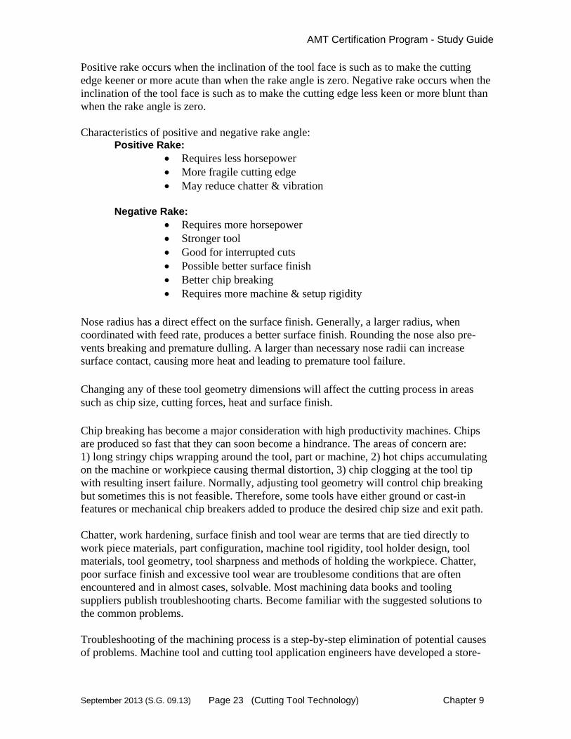
Positive rake occurs when the inclination of the tool face is such as to make the cutting edge keener or more acute than when the rake angle is zero. Negative rake occurs when the inclination of the tool face is such as to make the cutting edge less keen or more blunt than when the rake angle is zero. Characteristics of positive and negative rake angle:
Positive Rake: Requires less horsepower More fragile cutting edge May reduce chatter & vibration
Negative Rake:
Requires more horsepower Stronger tool Good for interrupted cuts Possible better surface finish Better chip breaking Requires more machine & setup rigidity
Nose radius has a direct effect on the surface finish. Generally, a larger radius, when coordinated with feed rate, produces a better surface finish. Rounding the nose also pre-vents breaking and premature dulling. A larger than necessary nose radii can increase surface contact, causing more heat and leading to premature tool failure. Changing any of these tool geometry dimensions will affect the cutting process in areas such as chip size, cutting forces, heat and surface finish. Chip breaking has become a major consideration with high productivity machines. Chips are produced so fast that they can soon become a hindrance. The areas of concern are: 1) long stringy chips wrapping around the tool, part or machine, 2) hot chips accumulating on the machine or workpiece causing thermal distortion, 3) chip clogging at the tool tip with resulting insert failure. Normally, adjusting tool geometry will control chip breaking but sometimes this is not feasible. Therefore, some tools have either ground or cast-in features or mechanical chip breakers added to produce the desired chip size and exit path. Chatter, work hardening, surface finish and tool wear are terms that are tied directly to work piece materials, part configuration, machine tool rigidity, tool holder design, tool materials, tool geometry, tool sharpness and methods of holding the workpiece. Chatter, poor surface finish and excessive tool wear are troublesome conditions that are often encountered and in almost cases, solvable. Most machining data books and tooling suppliers publish troubleshooting charts. Become familiar with the suggested solutions to the common problems. Troubleshooting of the machining process is a step-by-step elimination of potential causes of problems. Machine tool and cutting tool application engineers have developed a store-

AMT Certification Program - Study Guide
September 2013 (S.G. 09.13) Page 24 (Cutting Tool Technology) Chapter 9
house of experience that is essential in the ongoing process of successful machine tool sales. The application engineer should become the sale engineer's best friend.
MACHINABILITY Machinability is loosely defined as "The relative ease with which materials can be shaped by cutting, drilling, or other chip-forming processes." It is not an exact measurement or calculation due to the fact that it is dependent on both material and machining factors. The best situation occurs when material properties for both 1) workpiece application and 2) workpiece machinability, have been optimized.
Common Machinability Factors:
Material and Workpiece 1. Hardness 5. Microstructure 2. Tensile properties 6. Shape & dimension of workpiece 3. Carbon content 7. Abrasiveness 4. Chemical additives 8. Rigidity of workpiece
Machining Process
1. Tool life & wear 4. Cutting speed 2. Surface finish 5. Tool geometry 3. Cutting speed & force 6. Power consumption
Machinability charts for various materials are available in machining handbooks and from tooling suppliers. Due to the variation of the above factors, these charts should be used based on suggested ranges of machinability - not exact calculations. Several machinability tests have been established in an attempt to standardize the conditions and variables under which materials are to be rated. These tests are not agreed upon by all industry experts but can indicate relative performance from one material to another. Most ratings are relative to an established machinability rating of 100% based on SAE B-1112 (free-machining) steel. In comparison, titanium will have approximately 12 to 15% and aluminum 700 to 1000% machinability ratings. The application of the many technical aspects of cutting tool technology is only found in the actual machining process. This process requires the use of turning, milling, grinding, drilling, thread production and many other machining techniques.
CHIP CONTROL AND MANAGEMENT
The requirements of chip control and management largly depends on the type of material being machined and the amount of chips being produced.
Non‐ferrous materials ‐ aluminum can produce a large amount of chips that are light weight and they do not flow easily into the chip conveyance system. Special flood coolant systems are typically added to the machine tool to wash down the internal machine covers

AMT Certification Program - Study Guide
September 2013 (S.G. 09.13) Page 25 (Cutting Tool Technology) Chapter 9
during the machining process. Air blows, air blasts systems are also sometimes utilized to remove chips from the part or machine components. Abrasive or hard materials – required protective covers, special way wipers, air purges to machine components and vacuum systems should be considered to protect the machine tool to ensure long life. Ferrous materials ‐ these materials can require a combination of the solutions required for non‐ferrous and abrasive or hard materials.
Chip control within the machining process is not limited to only the internal machine components. Evacuation of the chips from the machining area should also be considered. Chip transfer conveyors such as a coil converyor or screw conveyor are sometimes incorporated into machining centers to move the chips to an eventual external chip conveyor. Depending on whether the chips produced are very fine, fine, c‐shaped or stringy long chips influences the selection of the chip conveyor. If the machine has an Automatic Tool Changer (ATC), a drum‐type chip conveyor may be a viable option to collect the very fine chips that could clog a thru‐spindle coolant system or prematurely wear the spindle.
See the chart below for an example of proper chip conveyor selection.
Fig. 8 – Proper Chip Conveyor Selection
(Courtesy of Okuma America)
COOLANT
AMT Certification Program - Study Guide
September 2013 (S.G. 09.13) Page 26 (Cutting Tool Technology) Chapter 9
Coolant performs several functions 1) physically pushes the chips from the cut to prevent them from attaching to the tool 2) lubricates the cutting process 3) assists in transferring heat from the tool to the chips being evacuated. High pressure coolant (typically in the range of 1,000 psi) can increase machine uptime. The benefits of high pressure coolant include increased machining rates and tool breakage control. High pressure coolant is useful for high speed drilling where chip evacuation is needed to insure proper or prolonged tool life. High pressure coolant is useful for turning high temp alloys or anytime extreme heat can be generated during the machining process. Coolant volume (gallons per minute) is a key specification to move chips from the cut and machining area and to remove heat from the machining process. High pressure coolant places a heavy load on the cutting fluid and the highest quality coolant is recommended. Applying high pressure to inferior coolant can result in foaming. Foaming reduces chip evacuation, lowering tool life and productivity. It can also flood a production floor with foam producing a safety hazard.
NOTES

AMT Certification Program - Study Guide
September 2013 (S.G. 09.13) Page 27 (Cutting Tool Technology) Chapter 9
9.6 Basic Machining Processes
TURNING & MILLING The word “machining” is a generic term applied to material removal. The term “metal cutting” refers to the process or processes in which excess material is removed from a part piece by a cutting type tool that is harder than the material being machined and through a process of extensive plastic deformation or use of a controlled fracture. The primary function of machining is to form a chip leaving the part piece as the by-product of the machining process. Metal cutting is customarily separated from non-traditional machining which is discussed in section 9.11 of this chapter of the Study Guide. In addition machining can be separated into:
Single point machining - associated with turning (OD), boring (ID) and facing operations, as well as shaping or planing.
Multipoint machining – associated with milling, drilling, sawing, broaching and grinding.
The two most common metal cutting processes are Turning and Milling and are further explained in the chart below:
TURNING MILLING Shape of workpiece Cylinder Prismatic (box-shaped)
Rotation Workpiece rotates Cutter rotates Cutting tool Single point Multiple cutting edges
Machining Centers & Spindle-Type Tooling There are many machining-center part programs requiring 30 or more different tools for their execution, and the programmer must know and be familiar with every one of the tools that he specifies. The contouring capability on many modern CNC’s permits end mills to be frequently substituted for large special boring tools in finishing large IDs. This approach is generally more economical. In many respects, the cutting tool determines the final dimensions of a workpiece. Consider a boring bar. The NC control unit may position the centerline of the boring bar exactly as it should be for machining the part.
Fig. 9 – Traditional Milling (Courtesy Decision Technology)

AMT Certification Program - Study Guide
September 2013 (S.G. 09.13) Page 28 (Cutting Tool Technology) Chapter 9
However, if the cutting tool insert has been improperly set, the bore will be either undersize or oversize. NC cannot control this. It can do nothing more than accurately position the machine spindle. Because an expensive machining center carries a high burden rate and because the setting of tools on the machining center may involve long periods of time, it is often deemed advisable to preset all tools of this type off the machine by a qualified person. The tools are preset into holders that are precision-made so that when the holders are inserted into the machine tool spindle the entire holder and cutting tool setup will be well within the programmer's working tolerance. High-quality toolholders will last a long time, but not forever. Over time, the holder's bore may become bell-mouthed and/or elliptical. This is usually not too obvious. Consequently, all toolholders and setscrews need to be inspected periodically. For less chatter when taking heavy cuts in sand castings and other tough materials, step-milling cutters often provide the answer. A number of configurations are available that mount teeth or blades irregularly, such as wavy-fluted end mills, stepped-blade face or shell mills, or differential blade face mills. For new-machine acquisitions, consider whether a machine will be needed that will accommodate an occasional overly long boring bar, or an extra-large diameter face mill (with adjacent pockets in matrix empty). Consider also whether the machine can be tooled for a completely different operation thereby eliminating use of a second machine. Turning & Lathe-Type Tooling Generally speaking, the part programs that are executed on a lathe or turning center involve only a limited number of cutting tools. Drills, reamers and boring bars do most of the ID (inside diameter) operations, and such tools are subject to pretty much the same guidelines as apply on other NC machine tools. Single-point lathe tools do some of the ID work and virtually all OD (outside diameter) operations such as turning, facing, grooving, and so on. Form tools are not commonly used anymore because of the contouring capability of today's CNCs. The machine tool design, and especially the tool turret configuration, may influence the selection of tooling. There are several approaches to the single-point lathe tool group:
First is preset tooling, a variation of insert-type tooling, where the toolholder incorporates the means for adjusting length or other characteristics. Tool adjustments to the exact dimensions stipulated by the part programmer are made in a special measuring machine or device. In one variation of this concept, the adjustment is made within a tool block, which permits use of standard straight-shanked tools. Preset tooling is made to either commercial or precision tolerances. Preset tooling is still used by many plants, but the tool compensation features of modern CNCs for lathes combined with the use of qualified tooling have substantially reduced the use of preset tooling.
AMT Certification Program - Study Guide
September 2013 (S.G. 09.13) Page 29 (Cutting Tool Technology) Chapter 9
Second is qualified tooling, which is made to much tighter tolerances than commercial grade tooling. Both toolholders and carbide or ceramic inserts are qualified to specific tight tolerances, providing an overall tight tolerance band. The more progressive NC users have almost universally accepted qualified tooling. Machine builders are designing for such tooling, and a specific machine may have slots provided in the turret face to accommodate certain size tools. With qualified tools, except for possibly the most precise cuts, two tools of the same designation are going to cut identically and a tool will cut the same after each index of the insert.
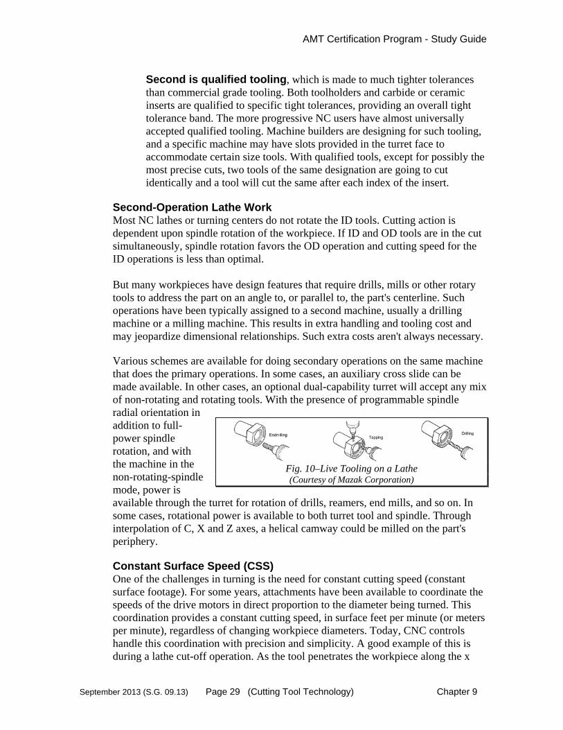
Second-Operation Lathe Work Most NC lathes or turning centers do not rotate the ID tools. Cutting action is dependent upon spindle rotation of the workpiece. If ID and OD tools are in the cut simultaneously, spindle rotation favors the OD operation and cutting speed for the ID operations is less than optimal. But many workpieces have design features that require drills, mills or other rotary tools to address the part on an angle to, or parallel to, the part's centerline. Such operations have been typically assigned to a second machine, usually a drilling machine or a milling machine. This results in extra handling and tooling cost and may jeopardize dimensional relationships. Such extra costs aren't always necessary. Various schemes are available for doing secondary operations on the same machine that does the primary operations. In some cases, an auxiliary cross slide can be made available. In other cases, an optional dual-capability turret will accept any mix of non-rotating and rotating tools. With the presence of programmable spindle radial orientation in addition to full-power spindle rotation, and with the machine in the non-rotating-spindle mode, power is available through the turret for rotation of drills, reamers, end mills, and so on. In some cases, rotational power is available to both turret tool and spindle. Through interpolation of C, X and Z axes, a helical camway could be milled on the part's periphery. Constant Surface Speed (CSS) One of the challenges in turning is the need for constant cutting speed (constant surface footage). For some years, attachments have been available to coordinate the speeds of the drive motors in direct proportion to the diameter being turned. This coordination provides a constant cutting speed, in surface feet per minute (or meters per minute), regardless of changing workpiece diameters. Today, CNC controls handle this coordination with precision and simplicity. A good example of this is during a lathe cut-off operation. As the tool penetrates the workpiece along the x
Fig. 10–Live Tooling on a Lathe (Courtesy of Mazak Corporation)

AMT Certification Program - Study Guide
September 2013 (S.G. 09.13) Page 30 (Cutting Tool Technology) Chapter 9
axis, the spindle speed is automatically increased to maintain a constant relationship of cutting speed (surface feet per minute) between the tool tip and the workpiece. Benefits include uniform surface finish and predictable tool wear. Quick-Change Lathe Tooling In the early eighties, an entirely new approach to lathe tooling began to make its appearance in the form of complete systems that must be provided for in the design of the lathe. Both ID and OD tools are included. Typically, the cutting unit itself looks much like its usual indexable-insert predecessor at the outboard end but, instead of a long steel shank, the insert holder is a stubby block that forms half of a unique coupling as shown in Figure 10. Clamping force is typically provided automatically by a drawbar. This type of system lends itself to automatic tool change, with many tools held in a storage matrix for ready retrieval upon programmed command. Several manufacturers now offer similar two-part block tooling systems. That part of the tool that is a semi-permanent resident in the tool turret constitutes a clamping unit into which the smaller traveling unit must be seated, registered and clamped. Several schemes have been developed for achieving the degree of registration accuracy required in a universal system. Similarly, systems have been introduced for automated quick change of chucks and upper chuck jaws on lathes (and grinding machines). Lathe Centers One advantage of lathe machining is being able to make shafts that are straight and concentric by turning them between centers. Some of the centers used on lathes are live centers (contain ball bearings), dead centers (solid) and half centers (top half is cut away). A dead center is the most economical, the live center allows for smooth rotation and low friction and the half center can be used when clearance is needed to machine the end of a part. Swiss-Type Automatic Screw Machines This unique turning machine is not, strictly speaking, a screw machine. Unlike a conventional screw machine, it uses single-point tools and a sliding headstock that feeds the stock through an adjustable carbide-lined guide bushing into the stationary cutting tools. These machines are typically used for precision instrument-type work with a range of 1/32 to 3/8” diameter stock capacity and 1/32” to 2-3/4” turning lengths. It is capable of producing long, slender, and complex contoured parts with a high degree of accuracy. Workpiece characteristics include bearing surfaces on small shafts typical of watches, electric meters and instruments. These machines are produced in both cam-actuated and CNC control configurations.
MULTI-TASK MACHINE TOOLING
AMT Certification Program - Study Guide
September 2013 (S.G. 09.13) Page 31 (Cutting Tool Technology) Chapter 9
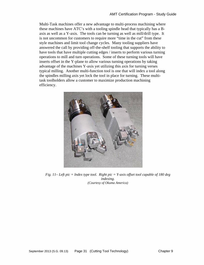
Multi-Task machines offer a new advantage to multi-process machining where these machines have ATC’s with a tooling spindle head that typically has a B-axis as well as a Y-axis. The tools can be turning as well as mill/drill type. It is not uncommon for customers to require more “time in the cut” from these style machines and limit tool change cycles. Many tooling suppliers have answered the call by providing off-the-shelf tooling that supports the ability to have tools that have multiple cutting edges / inserts to perform various turning operations to mill and turn operations. Some of these turning tools will have inserts offset in the Y-plane to allow various turning operations by taking advantage of the machines Y-axis yet utilizing this axis for turning verses typical milling. Another multi-function tool is one that will index a tool along the spindles milling axis yet lock the tool in place for turning. These multi-task toolholders allow a customer to maximize production machining efficiency.
Fig. 11– Left pic = Index type tool. Right pic = Y-axis offset tool capable of 180 deg indexing.
(Courtesy of Okuma America)

AMT Certification Program - Study Guide
September 2013 (S.G. 09.13) Page 32 (Cutting Tool Technology) Chapter 9
DRILLING & HOLE-MAKING Drilling is making or enlarging holes with a rotating tool fed into a stationary workpiece. Drills may also be used on a lathe in which case the workpiece rotates and the drill does not. Studies have indicated that the average machining center job is made up of 20 percent milling, 10 percent boring and 70 percent hole making, in machine cycle time. So, it would seem that the greatest gain in productivity can generally be achieved by placing the emphasis on making holes.
Twist Drills Drills are the most common cutting tools used in NC. HSS twist drills can be very troublesome if the user doesn't insist on the best-precision drills versus standard drills. A standard drill can vary considerably in lip height, flute spacing, web thickness, straightness and contouring of drill point. Even if its diameter is within tolerance, it's going to walk if its drill point is off center. Precision drills are a must, and the sharpening of worn drills must be to the same high standards. Helical (spiral) Tip Drills Helical-tipped drills, also called S-shaped drills. They have a point that is generated by reducing the drill point from a chisel edge to a helical (spiral) point. This produces an S-shaped chisel with a radiused crown effect. The highest point is at the center of the drill axis. This S-shaped chisel creates a continuous cutting edge extending from margin to margin across the web. These drills can be very productive in CNC applications.
Advantages are:
Self-centering capability. Reduction of thrust in some cases. Improved hole geometry. Improved hole size.
Disadvantages are: Possible burrs caused at hole breakthrough. Weaker than straight chisel points. Faster dulling when drilling hard materials. Special machines are used to grind points.
Indexable-Insert Drills Most successful NC users employ carbide-insert drills wherever possible. Other than permitting higher feeds and/or providing longer life, a major advantage of carbide-insert drills and other tools is that the tool is of constant length. When dull, the inserts are indexed to a new edge and the tool returned to service. When all cutting edges are used up, the insert is replaced. The tool and the toolholder are both left intact.
Fig. 12 -
Twist Drill
AMT Certification Program - Study Guide
September 2013 (S.G. 09.13) Page 33 (Cutting Tool Technology) Chapter 9
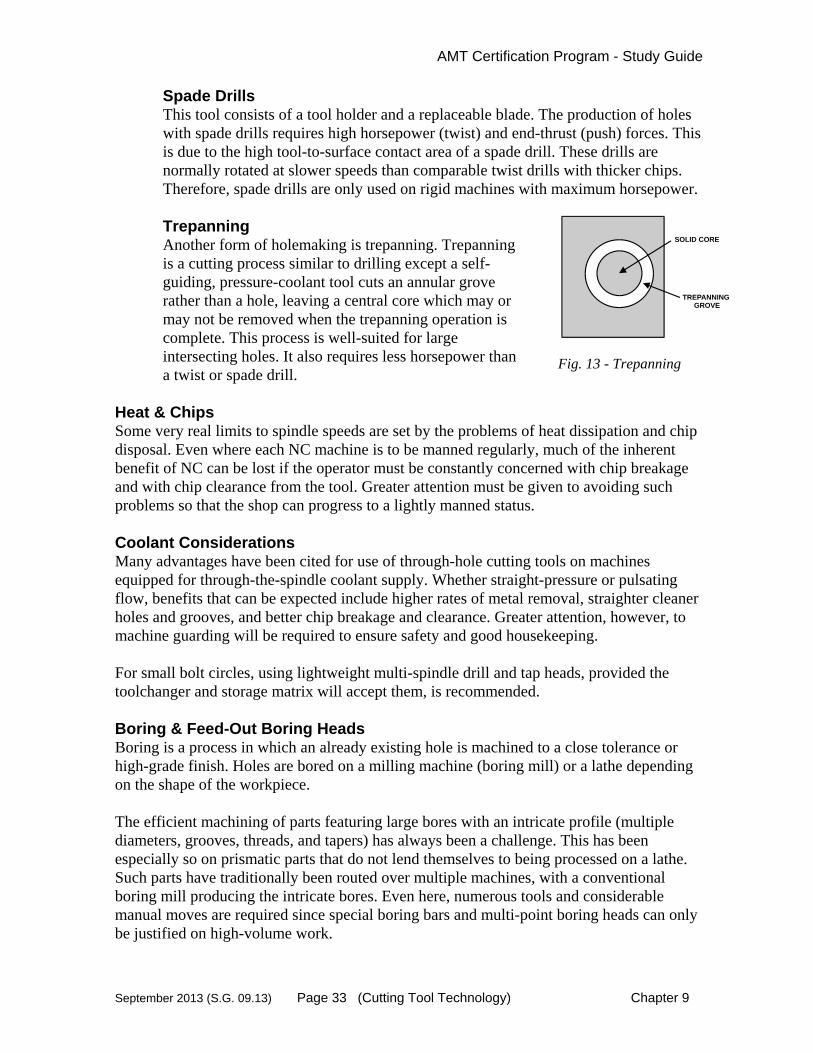
Spade Drills This tool consists of a tool holder and a replaceable blade. The production of holes with spade drills requires high horsepower (twist) and end-thrust (push) forces. This is due to the high tool-to-surface contact area of a spade drill. These drills are normally rotated at slower speeds than comparable twist drills with thicker chips. Therefore, spade drills are only used on rigid machines with maximum horsepower. Trepanning Another form of holemaking is trepanning. Trepanning is a cutting process similar to drilling except a self-guiding, pressure-coolant tool cuts an annular grove rather than a hole, leaving a central core which may or may not be removed when the trepanning operation is complete. This process is well-suited for large intersecting holes. It also requires less horsepower than a twist or spade drill.
Heat & Chips Some very real limits to spindle speeds are set by the problems of heat dissipation and chip disposal. Even where each NC machine is to be manned regularly, much of the inherent benefit of NC can be lost if the operator must be constantly concerned with chip breakage and with chip clearance from the tool. Greater attention must be given to avoiding such problems so that the shop can progress to a lightly manned status. Coolant Considerations Many advantages have been cited for use of through-hole cutting tools on machines equipped for through-the-spindle coolant supply. Whether straight-pressure or pulsating flow, benefits that can be expected include higher rates of metal removal, straighter cleaner holes and grooves, and better chip breakage and clearance. Greater attention, however, to machine guarding will be required to ensure safety and good housekeeping. For small bolt circles, using lightweight multi-spindle drill and tap heads, provided the toolchanger and storage matrix will accept them, is recommended. Boring & Feed-Out Boring Heads Boring is a process in which an already existing hole is machined to a close tolerance or high-grade finish. Holes are bored on a milling machine (boring mill) or a lathe depending on the shape of the workpiece. The efficient machining of parts featuring large bores with an intricate profile (multiple diameters, grooves, threads, and tapers) has always been a challenge. This has been especially so on prismatic parts that do not lend themselves to being processed on a lathe. Such parts have traditionally been routed over multiple machines, with a conventional boring mill producing the intricate bores. Even here, numerous tools and considerable manual moves are required since special boring bars and multi-point boring heads can only be justified on high-volume work.
SOLID CORE
TREPANNINGGROVE
Fig. 13 - Trepanning

AMT Certification Program - Study Guide
September 2013 (S.G. 09.13) Page 34 (Cutting Tool Technology) Chapter 9
In order to speed up production on boring mills, a class of boring heads that feature an adjustable-diameter tool slide perpendicular to the spindle centerline came into existence. The tool can be mounted to perform ID operations or OD operations. Tool diameter settings are achieved automatically by CNC. Radial feed of the tool slide is achieved by power feed. Much attention has been given to broadening the application of feed-out boring and facing heads to various CNC machines, including machining centers with automatic tool changing. The goal has been to fully program the U-axis tool slide and coordinate its feed with feed of the Z-axis machine spindle to produce tapers and contour bores. Combining the operations of boring and facing on a machining center permits a mostly prismatic part to be completed in one setup, thus reducing tooling and increasing productivity. Using a standard machining center toolholder adapter, one popular model feed-out head (Figure 14) can be interchanged in and out of the machine spindle just as any other tool assembly. To provide power to the head's tool slide, an auxiliary compact DC servo drive and feedback unit is mounted permanently to the machine adjacent to the spindle. When the head is loaded into the spindle, it also engages the drive unit, which secures the main body of the head in non-rotating oriented position. Radial motion of the tool slide can then be executed by U-axis command from the CNC, like any other machine axis. On some CNC’s, which do not provide for a U axis, control of the feed-out head's tool slide is shared with another axis. This usually limits the application of the head to straight bores and facing operations. To perform contours and tapers, the control must provide simultaneous U- and Z-axis interpolation.
HONING Honing is a process similar to boring in that an existing hole is enlarged to a precise size or polished to a smooth finish. Honing differs in that abrasive stones, instead of a boring tool, remove the stock. The type of abrasive stones used for honing will vary according to the hardness of the workpiece material and the amount of stock that must be removed. Often honing is used when a very close tolerance is required. A hole of several inches diameter can be honed to within .0005” - a better solution than boring, trepanning, or milling. On larger holes, above 4 inches diameter, honing can produce surfaces with respect to roundness and straightness within .001” to .0005”.
Standard V-FlangeToolholder Adaptor
Couples to Servodrive Unit
Linear Tool Slide on Rotating Inner Body
StationaryMain Head Body
Fig. 14 - This programmable boring and
facing head is easily interchanged between tool storage and machine spindle by typical
automatic toolchange systems. (Courtesy Gardner Publications)

AMT Certification Program - Study Guide
September 2013 (S.G. 09.13) Page 35 (Cutting Tool Technology) Chapter 9
Honing is the final machining step in the making of automobile engine block cylinder bores. The engine block is first machined then heat-treated. This hardens the material but also distorts the cylinder bore. Hardened holes are difficult to machine so excess stock is removed by honing. The honing process removes enough stock to produce a hole that is straight, a precise diameter and possessing a high-grade finish. All these qualities are essential to the operation of the completed automobile engine.
THREADING Threading is the process used to make standard spiral grooves on a cylindrical internal or external surface. There are many different kinds of threads; Unified inch, metric, and pipe threads, to name a few. To insure uniformity, manufacturers have developed precise standards for each type of thread. Because of this, thread making requires high standards of quality control. Its diameter and pitch determine the size of a thread. For example, a 1/2-13 inch threaded hole will accept a bolt that is approximately 1/2 inch in diameter. The 13 refers to the thread pitch which is 1/13 of an inch or .077. Lead is another term used to describe thread size. The lead of a thread is the amount it moves into a hole in one rotation. In the case of the 1/2-13 bolt the lead would be the same as the pitch - .077 inch, assuming that there was one start on the thread. Threads on the outside diameter (O.D.) of a part can be made on a lathe, a thread grinder, or by thread rolling. Inside diameter threads (I.D.) are usually made with a drill and tap, on a lathe or mill, or by thread grinding. Larger diameter threads can also be machined by utilizing a helical thread milling tool. To make a threaded hole a machinist selects the right size drill by consulting a chart for the thread he is making. A 1/2-13 thread requires a .4375 hole, which can be made with a 7/16- inch drill. Once the hole has been drilled to the correct depth a thread-cutting tool called a tap will be driven into the hole. The teeth on the tap will cut the helical groove we call a thread. Thread rolling is a process that is used to make large quantities of threaded fasteners. Threads are formed on cylindrical blanks that are rolled between hardened dies that have been machined to produce the desired thread size. Material on the blank is displaced rather than removed as in thread cutting or grinding. Thread rolling produces a thread that is hard, strong, and resistant to stripping.
GRINDING
Fig. 15 – Threaded Bar

AMT Certification Program - Study Guide
September 2013 (S.G. 09.13) Page 36 (Cutting Tool Technology) Chapter 9
Grinding machines are designed to imitate the action of a lathe (turning) or a mill. The difference with grinding is that the cutting tool is a rotating abrasive wheel. Because of this a grinder can machine very hard material and produce a superior surface finish. A more detailed description of grinding is given in the chapter titled Abrasive Tools and Machining. Refer to the chapter titled “Abrasive Tools & Machining” for more information on grinding. In the machine tool industry, each year sees the advent of more complex machines. A basic knowledge of machining process can help the machine tool sales engineer to understand these complex products.
NOTES

AMT Certification Program - Study Guide
September 2013 (S.G. 09.13) Page 37 (Cutting Tool Technology) Chapter 9
9.7 Workholding Considerations
WORKHOLDING & FIXTURES
Just as important as the toolholder is the workholding device. In fact, workholding is the most important item next to the cutting tool itself. On a machine tool, the workholding device grips the workpiece and presents it to the cutting tool for machining. The workpiece must be held with rigidity and alignment with respect to the machine tool if the part is to be properly machined. Workholders are used in: 1) turning, 2) boring, 3) milling, 4) drilling, 5) grinding and many other metalcutting and metalforming operations. Here is a review the basic functions of the workholder.
Hold the workpiece in proper location and alignment.
Hold the workpiece with the necessary rigidity to accommodate the cutting process. This must be done with little or no workpiece distortion.
Facilitate a rapid changeover of the workpiece. Allow rapid and positive loading and unloading
of workpieces. Reduce setup time of the workpiece. Facilitate a number of workpiece geometry
variations. This allows a family of parts to be machined in the fewest number of fixtures.
Easily adaptable to multiple machines. Workholding and fixture design is one of the most creative aspects of applying machine tools. It is both a science and an art honed by years of shop experience. Workpieces can be held by many means. The most common are mechanical, vacuum and magnetic and take one of the following common forms:
Collets Chucks Between centers Mandrels Clamps Vises Fixtures Jigs Magnetic plates
“The first function of a workholder is to establish the
correct relationship between the machine tool and the workpiece.”
Carr Lane Mfg.
Machine(Table)
Workpiece
Cutting Tool3
Tool Holder2
Machine(Spindle)
1
Workholder(Fixture)
5
4
6
Fig. 16 – Elements of Metalcutting
(Courtesy Decision Technology)

AMT Certification Program - Study Guide
September 2013 (S.G. 09.13) Page 38 (Cutting Tool Technology) Chapter 9
In addition to those above, creative solutions will involve many other devices and techniques. Workholders can be constructed from pre-designed or modular components or custom designed and fabricated.
Rotating Workpiece Workholders In turning and cylindrical grinding operations the workpiece is either machined between centers or in a chucking operation. Workholding devices such as collets, face drivers, mandrels, chucks and chucking fixtures will be selected based on the part configuration and machining operations. Some of the challenges include unsymmetrical or long parts (vibration), off-center turning, hollow stock and single-setup full OD turning.
Chucks The most common workholder on turning machines are chucks. The chuck must be sized for the lathes spindle nose configuration, rpm and swing. Rotational speed must be carefully specified because chucks have upper RPM limits. Centrifugal forces can pull the jaws outward and allow the workpiece to dislodge. Chucks are also used on some grinding machines that do chucking grinding.
3 & 6-Jaw Chucks The most common type of workholding for turning. Used for parts with a cylindrical griping surface. Most are centralizing.
2-Jaw & 4-Jaw Chucks Used for non-round and irregular shaped parts that must rotate on a centerline. Each jaw adjusts independently and balancing is required. Most are compensating.
Indexing Chucks For workpieces that have intersecting axes, such as valve and u-joint bodies. Jaws are custom made. Rotational speeds are limited.
Magnetic Chucks Grips irregularly shaped workpieces that have at least one flat surface. Limited to Ferrous workpieces and rotational speeds are limited.
Chuck Jaws Master jaws are those built-in to the chuck body. Top jaws are those jaws which affix to the master jaws via a serrated or geared surface and locking mechanism. Top jaws can a) clamp inward to grab outside diameters or b) clamp outward to grab inside diameters.
3-Jaw 4-Jaw
Fig. 17 – Chucks (Source: Fundamentals of Machining
& Machine Tools)

AMT Certification Program - Study Guide
September 2013 (S.G. 09.13) Page 39 (Cutting Tool Technology) Chapter 9
Automatic or Power Chucks The primary use is on CNC machines with foot-switch or control panel actuation. Most are powered by a draw bar or draw tube within the spindle. These chucks reduce load/unload time.
Thru-Hole Chucks Thru-hole chucks are commonly used on bar-feed equipped lathes.
Collets Collet chucks are the most rigid and accurate method of workholding on a turning machine. Collets clamp accurately on smooth or pre-machined outer diameter surfaces without damaging, marking or distorting the partpiece.
Standard Round Collets A popular workholder for round, cylindrical bar or slugs and generally used with bar feed. Square and Hex Collets A popular workholder for small, prismatic parts. Multi-Size Collets Used when a range of diameters is present. Spindle-Mounted Collets Direct Mount - Collets mount directly into the machine spindle. This requires a machine designed to receive collets. Adapter Mount - Collets mount into an adapter which is bolted to the spindle nose. Collet Chucks A chuck with an internal collet built-in instead of jaws. Collet chucks generally have higher clamping forces than a collet alone.
Between Centers Similar to many cylindrical grinding workholding configurations, this setup uses centers at both ends and a drive dog to transfer rotational power to the workpiece. They are used on parts where a chuck or collet is not practical. A face driver allows machining or grinding all the way to the end of the part.
Mandrels (arbors & expansion collets) It grips a workpiece on an inner diameter. They are good for thin-wall parts such as tubing and allow machining access to the entire outer surface. Face plates These are specially-fixtured face plates utilizing bolt and clamp attachments.

AMT Certification Program - Study Guide
September 2013 (S.G. 09.13) Page 40 (Cutting Tool Technology) Chapter 9
For use with large or non-round and irregular shaped parts that must rotate on a centerline, typical of VTL’s (vertical turning machines).
Tailstocks Tailstocks are used to support the end opposite the chuck or collet. This is a necessary accessory for turning long workpieces such as shafts. They can have a live or dead center.
Steady Rests Steady rests provide additional support for workpieces that lack rigidity such as those that are long and thin. They are generally located between the chuck/collet and the tailstock or can be located near the end of a workpiece (without a tailstock) to allow machining of the end of the part. Wear pads or rotating bearings are applied where they contact the workpiece.
Stationary Workpiece Workholders Stationary workpieces typical of milling, drilling and boring operations require a stationary fixture. Many times these are custom-engineered and assembled based on the workpiece configuration and required operations. Challenges include designing a fixture that adequately holds the workpiece but allows machining access to as much of the part as possible. Also, load-unload, clamping pressures, part distortion, chip removal, fixture cleanliness and part family flexibility are important considerations. The sales engineer should be familiar with the basic types and considerations for fixturing.
Clamps The most basic workholder for retaining a prismatic workpiece. Clamps can be either manually or hydraulically operated. Basic clamp types are:
Strap clamp Cam clamp Toggle-action clamp Hold down clamp Push-pull clamp Latch clamp
T-Slot (Tenon Slot) base plate or machine table Used for the simple retention of T-bolts in a machine table. They allow a reference for one axis.
Vises
CLAMP
WORKPIECE
MACHINE TABLE
Fig.18 - Strap Clamp Source: Decision Technology
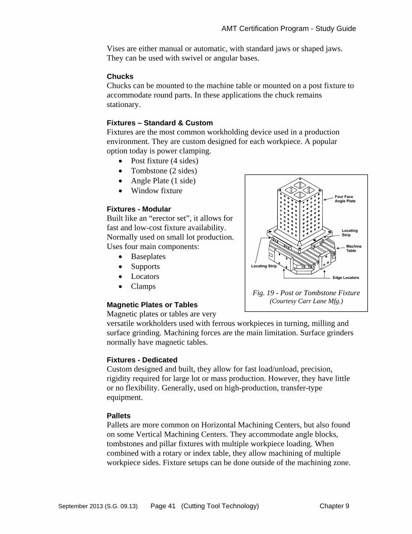
AMT Certification Program - Study Guide
September 2013 (S.G. 09.13) Page 41 (Cutting Tool Technology) Chapter 9
Vises are either manual or automatic, with standard jaws or shaped jaws. They can be used with swivel or angular bases.
Chucks Chucks can be mounted to the machine table or mounted on a post fixture to accommodate round parts. In these applications the chuck remains stationary.
Fixtures – Standard & Custom Fixtures are the most common workholding device used in a production environment. They are custom designed for each workpiece. A popular option today is power clamping.
Post fixture (4 sides) Tombstone (2 sides) Angle Plate (1 side) Window fixture
Fixtures - Modular Built like an “erector set”, it allows for fast and low-cost fixture availability. Normally used on small lot production. Uses four main components:
Baseplates Supports Locators Clamps
Magnetic Plates or Tables Magnetic plates or tables are very versatile workholders used with ferrous workpieces in turning, milling and surface grinding. Machining forces are the main limitation. Surface grinders normally have magnetic tables. Fixtures - Dedicated Custom designed and built, they allow for fast load/unload, precision, rigidity required for large lot or mass production. However, they have little or no flexibility. Generally, used on high-production, transfer-type equipment.
Pallets Pallets are more common on Horizontal Machining Centers, but also found on some Vertical Machining Centers. They accommodate angle blocks, tombstones and pillar fixtures with multiple workpiece loading. When combined with a rotary or index table, they allow machining of multiple workpiece sides. Fixture setups can be done outside of the machining zone.
Fig. 19 - Post or Tombstone Fixture (Courtesy Carr Lane Mfg.)
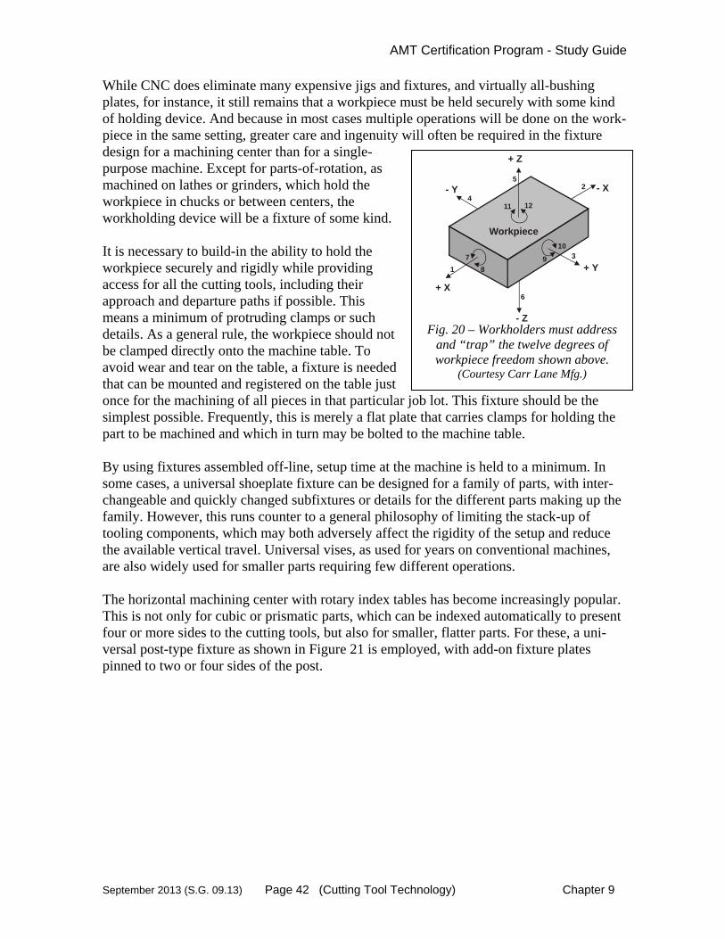
AMT Certification Program - Study Guide
September 2013 (S.G. 09.13) Page 42 (Cutting Tool Technology) Chapter 9
While CNC does eliminate many expensive jigs and fixtures, and virtually all-bushing plates, for instance, it still remains that a workpiece must be held securely with some kind of holding device. And because in most cases multiple operations will be done on the work-piece in the same setting, greater care and ingenuity will often be required in the fixture design for a machining center than for a single-purpose machine. Except for parts-of-rotation, as machined on lathes or grinders, which hold the workpiece in chucks or between centers, the workholding device will be a fixture of some kind. It is necessary to build-in the ability to hold the workpiece securely and rigidly while providing access for all the cutting tools, including their approach and departure paths if possible. This means a minimum of protruding clamps or such details. As a general rule, the workpiece should not be clamped directly onto the machine table. To avoid wear and tear on the table, a fixture is needed that can be mounted and registered on the table just once for the machining of all pieces in that particular job lot. This fixture should be the simplest possible. Frequently, this is merely a flat plate that carries clamps for holding the part to be machined and which in turn may be bolted to the machine table. By using fixtures assembled off-line, setup time at the machine is held to a minimum. In some cases, a universal shoeplate fixture can be designed for a family of parts, with inter-changeable and quickly changed subfixtures or details for the different parts making up the family. However, this runs counter to a general philosophy of limiting the stack-up of tooling components, which may both adversely affect the rigidity of the setup and reduce the available vertical travel. Universal vises, as used for years on conventional machines, are also widely used for smaller parts requiring few different operations. The horizontal machining center with rotary index tables has become increasingly popular. This is not only for cubic or prismatic parts, which can be indexed automatically to present four or more sides to the cutting tools, but also for smaller, flatter parts. For these, a uni-versal post-type fixture as shown in Figure 21 is employed, with add-on fixture plates pinned to two or four sides of the post.
+ X
- Z
+ Y
- X
+ Z
- Y
Workpiece
1
2
3
4
5
6
7
8
9
10
11 12
Fig. 20 – Workholders must address
and “trap” the twelve degrees of workpiece freedom shown above.
(Courtesy Carr Lane Mfg.)

AMT Certification Program - Study Guide
September 2013 (S.G. 09.13) Page 43 (Cutting Tool Technology) Chapter 9
Fig. 21 - A two- or four-sided universal post-type fixture with multiple predrilled mounting and locating holes for attaching part-dedicated fixture plates, greatly
extends the utility of a horizontal machining center, especially when the CNC has multiple-part program storage and alternate part program features.
(Courtesy Gardner Publications) The post-type fixture, which has the required mass for support against cutting forces, is left on the machine. The add-on fixture plates that carry the clamps can be light in weight, made from aluminum tooling plate, and easy to move and store. Especially on higher-volume work, there is renewed interest in clamping automatically--pneumatically or hydraulically; in order to further speed up loading and unloading. Aside from aerospace, the early applications of NC were primarily low-volume work; so auto-matic clamping was seldom used.
MODULAR FIXTURING Modular systems employ standard interchangeable base plates, subplates, mounting or riser blocks, clamping elements, and so on. In some systems, each element can be used with any other component to build a fixture. Each system employs a particular method to locate and mount the various attachments and accessories: a matrix of precision positioned holes, tee-slot arrangement, or slotted grid. The latter two are very adaptable in positioning components but do not lend themselves to
Fixture Plate
Workpiece
Rotary Index Table

AMT Certification Program - Study Guide
September 2013 (S.G. 09.13) Page 44 (Cutting Tool Technology) Chapter 9
precision repeatability when redundant fixtures are required or a fixture is rebuilt for a second run. A system that features the precision hole scheme favors high repeatability, but may not be as flexible when it comes to clamping. The precision positioned-hole-matrix method may use dowel holes, a combination of tapped and dowel holes, or just tapped holes. The advantages of modular fixturing include the shortened time required to design and build a fixture for a new product's entrance into production, and the savings in maintenance and storage. When a fixture has completed its mission, it can be disassembled and the components returned to inventory ready for use in another fixture.
NOTES

AMT Certification Program - Study Guide
September 2013 (S.G. 09.13) Page 45 (Cutting Tool Technology) Chapter 9
9.8 Special Applications & Part Runoffs
This study guide cannot be a substitute for detailed knowledge and work experience in the varied applications of cutting tool technology. Traditional machining operations normally include, turning, drilling, reaming, tapping, milling, boring and grinding. Less prevalent are the special applications of broaching, burnishing, threading, hobbing and sawing. The sales engineer should be familiar with the basic process in all of these metalcutting applications. In addition, he or she should also have knowledge in the specialized areas of gear making and threadcutting, which are not specifically covered in this text. Knowledge of cutting tool capabilities will enhance the machine tool sales engineer's position as a problem-solver with customers. A growing trend is for the customer to request not only a machine, but detailed processing, complete tooling and fixturing with a part runoff in the builder's plant. Occasionally, an additional runoff may be requested after installation in the customer's plant. This requirement can add considerable complexity to a machine sale, but provides valuable service to customers. Since workpiece processing is the heart of the manufacturing planning process, this value-added service should be taken seriously and cautiously. Qualified process and tooling engineers will be required to tackle this type of project. The sales engineer may act as a project manager in some cases and should communicate frequently with the project engineers. The proposal process may include logical step-by-step instructions for holding, handling, machining and inspection. The metalcutting process is complex and involves the interaction of many variables such as:
1. Detailed consideration of the workpiece material and "rough" part conditions. 2. Analysis of tolerance requirements. 3. Required fixturing and tooling. 4. Part orientation in initial and subsequent set-ups. 5. Type of machining operations, 6. Estimated feeds, speeds and depths of cut per operation. 7. Machine rigidity. 8. Verification of part machining. Frequently, the machine tool supplier will be
required to produce acceptable workpieces on the machine prior to final acceptance and payment. All proposals and subsequent contracts must clarify any guarantees regarding both cycle-times and tolerances.
9. Statistical Process Control may be applied to part tolerances which will place greater demand on the machine configurations

AMT Certification Program - Study Guide
September 2013 (S.G. 09.13) Page 46 (Cutting Tool Technology) Chapter 9
Normally, it is difficult to make guarantees once the customer assumes ownership of the machine and the supplier is no longer in control of the process. While guarantees may no longer apply after installation and runoff, it is in the best interest of the sales engineer to work with the customer in obtaining the desired production results. This will lead to additional orders in the future. While this portion of Volume II is followed by a very brief review of the grinding process, we encourage further study into the application of cutting tools. Please refer to the list of "Suggested Reading" in this volume. Please note this reading list includes subscriptions to trade publications that concentrate on specific areas of machine tool use. An additional source of continuing education is the many technical seminars sponsored by the SME (Society of Manufacturing Engineers) and other metalworking engineering societies. Active membership in one or more of these organizations is strongly recom-mended.
AMT Certification Program - Study Guide
September 2013 (S.G. 09.13) Page 47 (Cutting Tool Technology) Chapter 9
9.9 CNC Tool Management
(Portions adapted from and used with permission of Modern Machine Shop Magazine)
The best NC machine tool cannot remove metal from a workpiece unless there is a cutting tool in its spindle or turret and unless there is a fixture or chuck to hold the workpiece. And the machine won't be very productive without a great deal of thought and planning going into the proper selection and proper use of the tooling. One long-time trend has been that of combining operations; machining centers and turning centers. In recent years, success has been achieved in adding milling to a turning center or turning to a machining center, which had already largely replaced the standard milling machine. First-time NC users quickly come face-to-face with a very important fact of NC life. The tooling required can represent a very substantial additional investment. Good tooling is not only required, it is essential to reaping the full benefits of numerical control. If that first NC machine is a machining center with automatic tool changer and carrying up to several hundred tools in its storage matrix, the initial tooling costs will be impressive. And a big chunk of those costs will be for toolholders. The NC machining center is a multi-function machine. It will end mill, face mill, drill, bore and tap; it will perform nearly all of the required operations on a workpiece. Consequently, the cutting tools will cover a wide range of sizes, but they must all be made to look alike as far as the machine spindle and the tool change arm are concerned. In order for tools to be switched in and out of the spindle automatically, tools must have a collar or flange for the tool change arm to grab. Also, there must be a stud or other provision for the tool to be held securely in the spindle, by power drawbar for instance. The cost of adding these features directly on each and every cutting tool would be pro-hibitive, so a system of look-alike toolholders is necessary, Figure 22. Complete tooling systems are available from various suppliers. A particular system will have several basic styles of toolholders; arbor, fixed-lock, collet; to accommodate the broad range of cutting tools that may be needed. Adapters may or may not be needed for specific tools. The cutting tool and its holder are assembled off-line, and the entire tool assembly is loaded into the machine's tool storage matrix and subsequently selected and transferred automatically into the spindle as directed by the part program. Even though toolholders can be a sizable cost item, they can be justified as a long-term investment. For that 60+-tool machining center, the user needs not only the 60+ toolholders that would be on the machine at a given time but also enough additional toolholders to provide for the

AMT Certification Program - Study Guide
September 2013 (S.G. 09.13) Page 48 (Cutting Tool Technology) Chapter 9
constantly changing mix of parts to be machined. Some of the toolholders will be in transit between machine and toolroom. Some will be in the toolroom while tools are being reground and while tool kits are being made up for new parts being introduced into pro-duction. If such provisions are not made, the machine will be standing idle much of the time waiting for tools.
Fig. 22--For easy interchange of cutting tools on a specific machining center, externally alike toolholders are used. So that the same toolholder can be used on various machines and thereby keep tool inventories and tool handling costs to a minimum, most toolholders presently being made conform to an industry standard: ANSI B5.50 for tapered shank, V-flange toolholders. Dimensions are critical on flange, shank and retention knob. The ANSI standard covers six basic sizes from No. 30 through No. 60. Each machine will accept only one size: No. 50 is commonly used on horizontal machining centers that have from 30horsepower and higher. (Courtesy Gardner Publications)
TOOL MANAGEMENT PROGRAM Tool management involves good tooling policies, cost-effective part programming, stra-tegic use of tooling on the machine, and sound tool-related practices in toolroom, part programming, tool design, purchasing and possibly other off-line operations. The tool management program, of course, should embrace fixturing as well as cutting tools and other small tooling. Considerable computer software now exists to facilitate the various tasks of tool manage-ment. Some of this relates primarily to what happens on, at, or near the machine tool. But what happens elsewhere, off line, in support of good tooling on or at the machine, is also vital; and the computerization of those elements of tool management will be dealt with in a later chapter.
CUTTING TOOL POLICY The important point to consider is the vital necessity to have standards and procedures that are completely understood by the part programmer, shop supervisor, setup man, operator, and all others. The role and responsibilities of each in determining that the right cutting tool gets in the machine tool should be established as a matter of policy. These standards and procedures should all be firmly established before the CNC machine is made operational.
Gage Line
gV-Flange (Gripped by ToolInterchan e Arm)
Opposed Slots in Flange(for Drive and Orientation)
Hub(forToolSupport)
ID to SuitTool orAdaptor
Tapered Shank (to FitMachine Spindle)
Threaded-In Retention Knob(Typically Held by Power Drawbar)

AMT Certification Program - Study Guide
September 2013 (S.G. 09.13) Page 49 (Cutting Tool Technology) Chapter 9
A sound cutting tool policy is stated in the following four basic, important rules:
1. Have a set of cutting tool dimensional standards and make certain that all tools (except necessary specials) are purchased to these standards and are re-ground to the next size standard.
2. Use the shortest and most rigid cutting tool that can be applied to the job. More
loss of accuracy on NC machines comes from twist drills that walk because of improperly ground points; from long, weak drills that bend and wander; and from long end mills that flex and subsequently machine out of tolerance, than from any other source. Thus, cutting tool standards should concentrate on short, rigid tools.
3. Have rigidly determined policies about tool setting, regrinding and compensa-
tion. Who has the right to make tool compensations, set grinding standards and establish settings? Are settings to be made on the machine by the operator or off the machine by the operator, setup man, or toolroom? There should be clearly defined policies that are understood by the entire manufacturing division.
4. Use carbide and especially carbide indexable-insert type tools wherever possible
in preference to high-speed steel. (This is not to exclude ceramics or other advanced tool materials where appropriate.) The potentially higher productivity of NC machine tools, and the investment in such equipment, demands a longer and more constant wear life. Using indexable inserts eliminates a lot of time in regrinding tools and substantially reduces tool-setting time.
TOOL IDENTIFICATION Today, a CNC feature (usually called tool identification) permits the part program to call up a tool from the storage matrix by a tool assembly number five- to eight-digits long. (Some newer CNC units can accommodate longer numbers). Each number applies to a uniquely different tool. The operator via the CNC keyboard or remote tool management console assigns the tool assembly number to a specific pocket in the tool storage matrix either by tool data tape or. The use of tool assembly identification (I.D.) in this manner permits identical tools, with the same I.D., to be assigned to different pockets in the tool matrix, providing the basis for redundant tool selection.
AUTOMATIC TOOL IDENTIFICATION Two methods of automatic tool identification have now come into use. The first is the bar code designation. It is very similar to the bar codes used on products in stores with modern checkout lanes. As the code is passed over a scanner, it is read and the name and price of the item are automatically calculated, and displayed.

AMT Certification Program - Study Guide
September 2013 (S.G. 09.13) Page 50 (Cutting Tool Technology) Chapter 9
When used on machining centers, a bar code is established for each tool classification. The tool code is either etched or engraved on the tool. Another method uses a Radio Frequency ID chip in the tool holder and a Radio Frequency reader to automatically transfer data to the CNC. When the part program calls for a specific tool, the control unit searches for a particular tool code rather than calling for a specific location in the tool matrix. In this manner, the tool location in the matrix can be random. The tool does not have to be placed in a desig-nated pocket. The second automatic tool identification method makes use of a computer microchip embedded in the tool or in the holder shank. The microchip is programmed off-line with the tool identification number and other special information such as length or diameter compensation factors. The chip is read on the machine tool by a sensor head and all compensation or offset data is automatically entered into the CNC.
AUTOMATIC TOOL COMPENSATION Precision surface-sensing probes also are coming into use. In one type of application, the cutting tools are directed against the machine-mounted probe(s). At the moment of contact, the position of the machine tool slide(s) is recorded in the CNC and that data is processed by the control's computer to relate the tool's cutting edge to the programmed dimension. In another instance, the probe itself is mounted in a toolholder and placed in the machining center's tool storage matrix. When called for, it is transferred into the machine spindle and directed to probe a feature of the workpiece such as a surface or a hole. The probed information is then processed by the CNC to either redirect the cutting tools to compensate for any deviations or to relate the cutting tools to the physical location of the workpiece. Such probing applications require a CNC with a special compensating software routine.
SEMIAUTOMATIC COMPENSATION - TOOL LENGTH & DIAMETER
Some CNC units offer another method of setting tool compensation. A tool is mounted in the spindle or turret station and then brought into machining position. The operator jogs it against a reference stop and its position is automatically recorded in the control. With this information the control's computer modifies all part program statements to take into account the length of the drill, diameter of the end mill, location of the insert, and so on. Figure 23 illustrates one such feature.

AMT Certification Program - Study Guide
September 2013 (S.G. 09.13) Page 51 (Cutting Tool Technology) Chapter 9
Fig.23 - With semiautomatic tool compensation, the pro-grammer figures the same basic tool length for all tools and the operator at setup time aligns each tool in turn against a fixed reference point on the machine. At the press of a button, the CNC calculates the difference between the tool's actual length and the basic tool length and enters that differential into memory as a compensation value. (Courtesy Gardner Publications)
TOOL LENGTH COMPENSATION
This software permits a certain number of Z-axis compensation or correction values for fine tuning of tool length, or more commonly for minor part or setup variations. The trim value is typically allowable in increments of 0.0001 inch up to 1.0000 inch and is input by the operator.
CUTTER DIAMETER COMPENSATION (MILLING) This software feature basically alters a milling cutter's programmed centerline path to compensate for a small difference in cutter diameter. On most CNCs, it is effective on vir-tually any cut made using either linear or circular interpolation in the X-Y plane but does not affect the programmed third-axis moves. Typically, compensation is in increments of 0.0001 inch up to 1.0000 inch. In addition to permitting use of cutters that have been sharpened to a smaller diameter, the cutter diameter compensation (CDC) feature may also permit:
1. Using a larger or smaller tool already in the machine's storage matrix. 2. Backing off for a preliminary rough cut where excessive stock is present. 3. Compensating for unexpected tool or part deflection, if the deflection is constant
throughout the programmed path.
CompensationValue
Fixed Reference Point Basic Tool

AMT Certification Program - Study Guide
September 2013 (S.G. 09.13) Page 52 (Cutting Tool Technology) Chapter 9
TOOL NOSE RADIUS COMPENSATION (TURNING) This software feature basically alters the programmed path of a single-point tool to compensate for a difference in the tool’s nose radius. In turning operations such as straight faces or straight diameters, the tool nose radius has little or no effect on the final part dimension. However, when turning contoured parts, the tool contacts the part at multiple nose locations. The programmed tool path calculations are always based on a specific nose radius dimension. If the nose radius changes due to using a tool different than that programmed, a tool nose radius compensation must be used. This technique is especially useful for finishing operations on contoured parts.
TOOL LIFE MONITOR This software feature enables the CNC to keep track of the total time spent in actual feed cycle by each tool on the machine. By continuously accumulating this time and comparing it with a life expectancy value programmed into the CNC for that tool, the remaining tool usage time is computed automatically. While the tool is active, the remaining usage time is displayed and when that time runs out, an alert message signals that action must be taken.
REDUNDANT TOOL With this software feature, tools that are common to most part programs or otherwise see heavy usage can have identical backup tools in the tool storage matrix. Combined with tool usage monitor, this feature causes the CNC to automatically substitute an identical tool at the first opportunity when a tool's usage has expired. This would normally be the next time the specific tool identification is called by the part program. The redundant tool feature could also be linked to torque sensing or some other sophisti-cated device for indicating need for tool replacement. This is more economical and safer than using a predetermined tool life expectancy.
FIXTURE OFFSETS Among the features available on various CNCs to facilitate setup and workholding, the fixture offsets feature is of outstanding importance; especially for critical work. They allow the operator to compensate for a dimensional error in the fixture or its location, or in the part. It permits the operator to enter a separate error value in each of the axes involved.
Tool Nose Radius Compensation
Fig. 24 – Nose Radius
Compensation

AMT Certification Program - Study Guide
September 2013 (S.G. 09.13) Page 53 (Cutting Tool Technology) Chapter 9
This feature is invaluable where work is located on a rotary index table as shown in Figure 25. If the operator finds the fixture is off center, a one-time correction in X, Y and Z-axes through fixture offsets will permit machining to proceed on all sides of the part as if the fixture were on center. At each index, the tables will automatically zero shifts as needed. Also, a part may have some feature like a boss (to be hollow milled) or a cored hole (to be drilled) that may vary in position from lot to lot, but not piece to piece within the lot. The part programmer can put a fixture-offset code on the machining of that feature. When the first piece of a new lot comes through, the operator determines the error in position of that part feature and enters the appropriate value or values through the CNC keyboard. On all subsequent pieces of that job lot, the machine will automatically zero shift for those operations. Or, the programmer might be faced with a situation where the relationship of a small group of part features, one to the other, is more precise and more important than overall part feature relationships.
Fig. 25 - Fixture offsets are H-coded, two-digit words; if 16 offsets are available, the offset designation ranges from H00 to H16. For each H-code designated in the part program, separate offset values can be established for up to three axes. Offset values remain in effect until canceled by a new H-code or end of program. When very close tolerance work is fixtured on a rotary index table, separate H-codes may be assigned to each major index position whether machining on four sides or using a post-type fixture for multiple setups. For most work, one set of offsets may suffice. For very close tolerances, it may be necessary to calculate different offsets for workpiece A and for workpiece B. (Y-axis offset is not shown here.) (Courtesy Gardner Publications)
TOOLING DOCUMENTATION Good communications and documentation are essential to CNC success. The basic objective is to have an accessible and readable record of everything pertaining to processing a part. All concerned need a common, clear basic understanding of what is going to happen, what is happening, and what has happened. What is important is that all tooling-related activities be subject to a well-structured discipline. The result will be good, effective tool management.
180
270 90
0
Z Offset
Rotary Index Table
X Offset
Index Table Centerline
Workpiece A
Workpiece B
Post Type Fixture

AMT Certification Program - Study Guide
September 2013 (S.G. 09.13) Page 54 (Cutting Tool Technology) Chapter 9
9.10 Abrasive Tools & Manufacturing
Abrasive machining is probably the oldest form of metalcutting, dating back to the Stone Age. It is the process of removing workpiece material by means of the small cutting edges of abrasive grains. Today, this process is best typified by grinding but also includes other processes such as lapping, polishing, honing, abrasive belt and abrasive cutoff. Grinding is the single most, widely used metalcutting process in industry. Grinding offers many benefits and therefore finds a wide range of applications. These benefits can be summarized as follows:
1. Excellent surface finish. 5. Rough & finish in one operation. 2. Variable stock removal rates. 6. Simplified work holding. 3. High-precision size control. 7. Machining of hard steels & 4. Form production via the wheel. superalloys.
Grinding machines fall into 6 basic groups: 1) Surface grinders, 2) Disc grinders, 3) Center-type cylindrical grinders, 4) Internal cylindrical grinders, 5) Centerless grinders, and 6) Tool-and-cutter grinders. Surface grinders can have either horizontal or vertical spindles in combination with either reciprocating or rotary tables. There are many variations of the above machine types as well as special machines such as thread grinders.
1. Surface grinders - produce precisely flat surfaces on a workpiece. 2. Disc grinders - for deburring, grinding chamfers, and rough tool sharpening. 3. Center-type cylindrical grinders - for grinding the OD (outside diameter)
of a part that can be held between centers. 4. Internal cylindrical grinders - for grinding the ID (inside diameter) of a part
held on a rotating chuck. 5. Centerless grinders - for grinding the OD of cylindrical parts that cannot be
held between centers. 6. Tool and cutter grinders - for precise sharpening of metal cutting tools.
ABRASIVE TYPES Up until 100 years ago the only abrasives in use were abrasives found naturally in the envi-ronment. Some of these are still in use today. In the 1890's two new man-made abrasives came on the scene: 1) Silicon Carbide and 2) Aluminum Oxide. These two have been very popular and still account for approximately 90% of the abrasives used today in America. Aluminum oxide is the single most used abrasive comprising almost 70% of our domestic market. The 1950's saw the next leap forward with GE developing both Cubic Boron
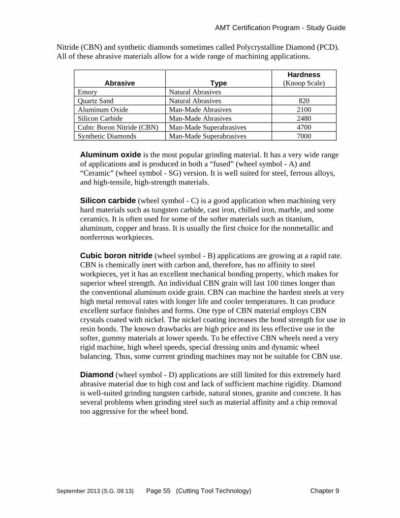
AMT Certification Program - Study Guide
September 2013 (S.G. 09.13) Page 55 (Cutting Tool Technology) Chapter 9
Nitride (CBN) and synthetic diamonds sometimes called Polycrystalline Diamond (PCD). All of these abrasive materials allow for a wide range of machining applications.
Abrasive
Type
Hardness (Knoop Scale)
Emory Natural Abrasives Quartz Sand Natural Abrasives 820 Aluminum Oxide Man-Made Abrasives 2100 Silicon Carbide Man-Made Abrasives 2480 Cubic Boron Nitride (CBN) Man-Made Superabrasives 4700 Synthetic Diamonds Man-Made Superabrasives 7000
Aluminum oxide is the most popular grinding material. It has a very wide range of applications and is produced in both a “fused” (wheel symbol - A) and “Ceramic” (wheel symbol - SG) version. It is well suited for steel, ferrous alloys, and high-tensile, high-strength materials. Silicon carbide (wheel symbol - C) is a good application when machining very hard materials such as tungsten carbide, cast iron, chilled iron, marble, and some ceramics. It is often used for some of the softer materials such as titanium, aluminum, copper and brass. It is usually the first choice for the nonmetallic and nonferrous workpieces. Cubic boron nitride (wheel symbol - B) applications are growing at a rapid rate. CBN is chemically inert with carbon and, therefore, has no affinity to steel workpieces, yet it has an excellent mechanical bonding property, which makes for superior wheel strength. An individual CBN grain will last 100 times longer than the conventional aluminum oxide grain. CBN can machine the hardest steels at very high metal removal rates with longer life and cooler temperatures. It can produce excellent surface finishes and forms. One type of CBN material employs CBN crystals coated with nickel. The nickel coating increases the bond strength for use in resin bonds. The known drawbacks are high price and its less effective use in the softer, gummy materials at lower speeds. To be effective CBN wheels need a very rigid machine, high wheel speeds, special dressing units and dynamic wheel balancing. Thus, some current grinding machines may not be suitable for CBN use. Diamond (wheel symbol - D) applications are still limited for this extremely hard abrasive material due to high cost and lack of sufficient machine rigidity. Diamond is well-suited grinding tungsten carbide, natural stones, granite and concrete. It has several problems when grinding steel such as material affinity and a chip removal too aggressive for the wheel bond.

AMT Certification Program - Study Guide
September 2013 (S.G. 09.13) Page 56 (Cutting Tool Technology) Chapter 9
WHEEL SELECTION When selecting the correct grinding wheel for a machining application a number of factors must be considered. These include, but are not limited to:
1. Mechanical and thermal shock. 2. Affinity of the workpiece material to the abrasive. 3. Hardness of the workpiece. 4. Shape and size of the abrasive grain. 5. Friability of the abrasive. 6. Wheel bonds, structure and speed. 7. Abrasive coatings. 8. Wheel form and dressing techniques.
WHEEL DRESSING The abrasive machining process requires that the abrasive product be friable. Friability refers to the expected nature of the abrasive to fracture during the grinding process. In other words, the wheel must wear down in order to expose new, sharp cutting edges. Since the form or shape of the grinding wheel is extremely important it is necessary to renew the face of the wheel on a regular basis. This process is called dressing and is accomplished by 1) crush, 2) diamond roll or 3) single-point diamond profile dressing. CNC controlled machines can be programmed to use a dressing station in forming a new wheel profile.
WHEEL BALANCING Grinding wheel spindle vibration can adversely affect surface finish, part geometry, wheel wear, grinder burn and productivity. A number of factors can contribute to wheel imbalance situations, such as out-of-roundness and coolant issues. Wheels should be spun without coolant to evacuate the coolant from the wheel. When wheels are stationary, remaining coolant settles at the bottom of the wheel and can cause severe out-of-balance during startup of wheel rotation. Three common ways to balance the grinder spindle are: 1) arbor weights, 2) servo motor mechanical weight systems and 3) sophisticated, automatic wheel balancing. This third system is a “no moving parts” solution that uses a spindle-mounted unit with four (one per quadrant) hollow chambers filled with a liquid/gas substance such as Halon. The on-board microprocessor directs electrical power to heating elements imbedded in the hollow chamber on the “heavy” side of the unit. The heating element vaporizes the high-density fluid (i.e. Halon), forcing it to the chamber on the opposite side. This chamber is cooler and the gas condenses back to a liquid, resulting in a balanced condition. Balancing is normally required when a surface finish of 50 micro inches or lower is required.
WHEEL IDENTIFICATION

AMT Certification Program - Study Guide
September 2013 (S.G. 09.13) Page 57 (Cutting Tool Technology) Chapter 9
Two similar classification-coding (USA) schemes apply to grinding wheels. The first is for standard bonded-abrasive wheels and the second is for superabrasive wheels. This makes selection a simple process once the machining requirements have been established. For example, a wheel designation of C70M7V is charted below. The sales engineer will be most concerned with the 1) Abrasive type; 2) Grain size; 3) Grade; 4) Structure; and 5) Bond type.
Standard Bonded-Abrasive Wheels Prefix Abrasive
Type Grain Size
Grade Structure Bond Type Mfgr's. Record
47 C 70 M 7 V 42 Mfg.'s
code for A
Aluminum Coarse
8 Soft A
Dense 1
V-Vitrified S-Silicate
Mfg.'s private
specific abrasive
C Silicon
R-Rubber B-Resonid
code (optional)
(optional) carbide Fine 600
Hard Z
Open 15
(optional)
E-Shellac O-
Oxychloride
(For a complete chart refer to an abrasive catalog or reference manual)
Superabrasive Wheels Prefix Abrasive
Type Grain Size
Grade Concen-tration
Bond Type
Depth of Abrasive
Mfgr's. Record
50 B 36 L 75 V 1/8 32 Mfg.'s
code for B
CBN Coarse
8 Soft A
Mfg’s code may
V-Vitrified M-Metal
Mfg.'s private
specific abrasive
D Diamond
be number or symbol
R-Resin
code (optional)
(optional) Fine 600
Hard Z
(For a complete chart refer to an abrasive catalog or reference manual)
COATED ABRASIVES Coated abrasives are another popular abrasive application. These “tooling” items consist of various abrasive grains mounted to flexible sheets, discs, rolls and belts to provide a number of grinding, finishing and polishing capabilities. Obviously, the bonding technology is critical to a successful application. Coated abrasive materials include aluminum oxide, zircona alumina, silicon carbide, superabrasives, garnet, emery, crocus and flint. Coated abrasives are used on automatic, semiautomatic, in-line and other mass production equipment.

AMT Certification Program - Study Guide
September 2013 (S.G. 09.13) Page 58 (Cutting Tool Technology) Chapter 9
9.11 Non-Traditional Machining
LASER, EDM, ECM & WATER JET
Non-traditional machining includes a host of unique processes too varied to completely discuss in this Study Guide. Four common non-traditional methods will be discussed which are: 1) Laser Beam Machining - LBM, 2) Water Jet or Hydrodynamic Machining, 3) Elec-trical Discharge Machining - EDM, and 4) Electrochemical Machining - ECM.
LASER BEAM MACHINING (LBM) Laser beam technology uses monochromatic light to do a variety of machining operations. Cutting, hole-making, welding, heat treating, alloying, cladding, coating, scribing, deflash-ing, stripping, marking and measuring are all being done with lasers. The laser beam is either continuous or pulsed depending on the application. The laser beam actually melts, and then vaporizes most metals. Simultaneous to this a stream of gas (usually oxygen) is directed to the operation to blow the residue away. In some cases the gas is selected because of its reaction to the workpiece material. Laser machining units require a large power source, which dictates a large power supply station. The best metal applications are those, which are thin. CNC control systems have allowed laser machines to be consistent and easily controlled. Some laser machining advantages are:
1. Reduced cutting forces. 2. Better chip management. 3. Little noise and vibration. 4. Handles complex shapes. 5. Small heat-affected zone (10 to 20% of kerf). 6. Narrow kerf (small as 0.004). 7. No fumes in steel (some in plastic). 8. Good for shallow blind holes. 9. Accurate welding of thin sheets

AMT Certification Program - Study Guide
September 2013 (S.G. 09.13) Page 59 (Cutting Tool Technology) Chapter 9
HYDRODYNAMIC MACHINING (HDM) & WATER JET MACHINING (WJM)
Hydrodynamic Machining and its lower pressure version called Water Jet Machining use the force of a high-pressure stream of water to remove workpiece material. If sharp work-piece edges are a requirement (easier on soft parts) then Polymers are added (e.g., glycerin) are added to the water to improve jet coherency. Cutting force is determined by jet velocity, which is determined by water pressure and nozzle size. Cutting and slitting of thin metallic and non-metallic parts are the preferred applications. Look for workpiece materials such as wood, paper, asbestos, plastics, gypsum, leather, felt, rubber, nylon, fiberglass, carpet, ceramic sheet, stone and concrete. Benefits of this type of machining include little or no tool wear, low noise and heat, small kerf, low side forces (minimal fixturing) and ability to cut complex shapes. CNC con-trolled, 2 axis machines are predominant, but 3-axis control allows exact control of nozzle standoff distance on contoured surfaces. Considerations are water filtration and nozzle standoff distances. Normally these machines are custom built based on the application.
ELECTRICAL DISCHARGE MACHINING (EDM)
Electrical Discharge Machining is a major departure from other machining processes. Workpiece material is removed by erosion (melting and vaporization) causes by an electrical discharge (spark) between the electrode (acting as a tool) and the workpiece. The electrode does not touch the workpiece. The workpiece must be electrically conductive because it
acts as the opposite electrode in the process. The workpiece is submerged in a dielectric fluid, which initially acts as an insulator between the electrode and workpiece. As the charge builds up on the electrode it reached a strength that ionizes the dielectric fluid (breaks down insulating qualities) and the spark jumps across to the workpiece. One of the primary purposes of the dielectric fluid is to flush the residual machining particles out of the spark gap. Primary applications for EDM can be found in the tool and die, mold making, electronic and aerospace industries. Any requirements for odd shaped holes, intricate cavities, slots and
Tool (electrode)
Workpiece
Dielectric
Fig. 26 - Ram-Type EDM (Courtesy Decision Technology)
Fig. 27 -Wire EDM (Source: Fundamentals of
Machining & Machine Tools)

AMT Certification Program - Study Guide
September 2013 (S.G. 09.13) Page 60 (Cutting Tool Technology) Chapter 9
contours, and small fragile parts lend themselves to EDM. It is especially useful for machining very hard materials such as tool steel. Remember that the workpiece must be electrically conductive. CNC controls make contouring cavity work accurate and programmable.
ELECTROCHEMICAL MACHINING (ECM) In Electrochemical Machining, the metal removal process is accomplished by electrolytic means, which combines electrical energy and chemicals to cause a reverse plating action. The mechanics of the process include a cathode tool that is formed in the shape desired on the workpiece. The workpiece becomes the anode and an electrically charged electrolytic fluid (electrically conductive - usually sodium chloride) flows between the cathode tool and the anode workpiece. The erosion of surface atoms takes place after the electrolyte breaks down the metallic surface bonds on the workpiece. The shaped cathode tool penetrates as the erosion, or reverse plating, takes place leaving its shape impressed on the workpiece. ECM has a wide variety of applications. Hard metals with irregular internal or external features are good candidates for this process. ECM can perform sawing, wire cutting, trepanning, surfacing, drilling, turning and deburring.
NOTES

AMT Certification Program - Study Guide
September 2013 (S.G. 09.13) Page 61 (Cutting Tool Technology) Chapter 9
9.12 Review Questions
These review questions are provided for study purposes only and are not on the CMTSE certification exam. Correctly answering these questions does not guarantee a passing exam grade.
1. The annealing process affects a steel workpiece by: 1. increasing surface hardness. 2. increasing machinability. 3. changing the nickel content. 4. decreasing the workpiece size. 2. EDM uses what process to remove metal? 1. Abrasive 2. Cutting 3. Erosion 4. Reverse plating 3. A reamer is a rotary cutting tool used for: 1. cutting bar stock for chucking work. 2. broaching a keyhole slot. 3. milling threads in a large diameter hole. 4. accurately finishing a hole to a specified size. 4. Stainless steel is high in what alloying element? 1. Magnesium 2. Nickel 3. Sulfur 4. Chromium 5. In the designation C100K14V, the letter V - according to the standard grinding wheel
marking system - refers to: 1. grade. 2. grain. 3. abrasive type. 4. bond type. 6. High-speed steel would be better than ceramic tooling for: 1. interrupted cuts. 2. machining stainless steel. 3. turning centers. 4. high feedrate machining.

AMT Certification Program - Study Guide
September 2013 (S.G. 09.13) Page 62 (Cutting Tool Technology) Chapter 9
7. A non-ferrous metal is: 1. low-carbon steel. 2. white cast iron. 3. magnesium. 4. tungsten steel. 8. At a constant feedrate, improved surface finish would most likely be a result of: 1. increasing depth-of-cut. 2. increasing nose radius. 3. increasing horsepower. 4. removing any chip-breakers. 9. A good method of making threads in a large (12" dia.) hole is: 1. broaching. 2. 3-axis contour milling. 3. using a floating tap. 4. using high-speed formed tools. 10. In SAE 4150 the "50" refers to the: 1. type of alloying element. 2. Rockwell hardness. 3. carbon content. 4. sulfur content. 11. Which of the following is not a direct result of tool chatter? 1. Poor surface finish 2. Diminished tool life 3. Coolant contamination 4. Compromised workpiece dimensional tolerance 12. Machine mounted surface-sensing probes are usually used to: 1. assist in adaptive control of machine spindle. 2. monitor machine slide position. 3. determine tool length compensation automatically. 4. detect machine vibration.

AMT Certification Program - Study Guide
September 2013 (S.G. 09.13) Page 63 (Cutting Tool Technology) Chapter 9
ANSWERS TO REVIEW QUESTIONS 1. (2) 2. (3) 3. (4) 4. (4) 5. (4) 6. (1) 7. (3) 8. (2) 9. (2) 10. (3) 11. (3) 12. (3)

AMT Certification Program - Study Guide
September 2013 (S.G. 09.13) Page 64 (Cutting Tool Technology) Chapter 9
Notes