customized measuring instruments in ... - m-tec … · customized measuring instruments in modular...
TRANSCRIPT

C US TO M I Z E D M E A SU R I N G I N S T R U M E N T S I N M O D U L A R S Y S T E M S

2
The advantages of this modular system- quick, easy handling, individual setting
options and intelligent combinations with different components- offer the user
both cost benefits as well as numerous possible applications.
This testing apparatus is equipped for extensive measurements for all turning
and milling parts. The product range includes systems for measurement of
different diameters, heights, hole sizes, distances, concentricity and a new multi-
function measuring table.
The devices may be customized as per
individual specifications on request.
www.m-tec-messsysteme.com
BUILT ON EXPERIENCE, INNOVATION AND PRECISION

3
MODULES
THE M-TEC SYSTEM
from page 6
from page 4
from page 20
from page 22
from page 24
COMPONENTS
EXAMPLES AND OPERATING INSTRUCTIONS
ASSEMBLIES
All assemblies and modules are delivered by default without measuring
equipment.
Upon request, the assemblies can be also equipped with measuring clock or
incremental push buttons.
Storage cases can be supplied on request.
BEISPIELFOTO
PLEASE NOTE
Measuring suitcase
Contents
1X Auxiliary support pad MD-4020
2X Measuring bracket U-profile MD-5000
2X Measuring bracket L-profile MD-5010
1X Universal swivel arm MD-3010
1X Basic profile MD-2000
2X Angle bracket MD-3020
1X Gap gauge 0-50 mm MD-5030
1X Measuring plate Ø 50mm KM-1013
1X Profile column MD-3000
1X Master sample
Assembly tools
INH
ALT
SVER
ZEI
CH
NISTABLE OF CONTENTS

4
The modular measurement technology always
consists of hard-anodized aluminium basic profile
with steel side parts and different accessories in
order to perform a first simple measurement.
The modular system of M-TEC offers the right solution for almost
every application.
It can also be used with all latest measuring clocks and electronic
sensors with a clamping shaft of φ 8mm. You can also use
micrometer gauge for radial run-out measurement in boreholes.
The measurement of diameters, run-out, heights, holes, distances
and roundness by arranging different intelligent components,
guarantee cost savings and above all, simple and precise
measurement processes.
The construction of a measuring device is composed of a basic
profile with combinable modules together, which can be adjusted
quickly and easily (the modules can be installed with just one
tool).
The devices are calibrated with a gauge and are at all times in
the workshop (on the machine) to support the worker in giving
immediate proof of the quality of his products.
You can make several measurements with one measuring device
in smallest possible place, thus saving valuable space on the
machine.
A gain of affordable production safety directly in the
manufacturing, results in fewer complaints and employee
satisfaction.
Supplements for different modules are available:
Centering points
Measuring clock holder
Measuring bracket L-Profile
Measuring bracket U-Profile
Angle bracket
Brass coating to prevent damage on the test
piece
ASSEMBLIES
MODULES DETAILS
THE
M-T
EC S
YSTE
M CUSTOMIZED MEASURING INSTRUMENTS IN MODULAR SYSTEMS

5
1. MEASURE UPPER GROOVE
3. MEASURE INTERMEDIATE GROOVE
4./5. MEASURE HEIGHT AND LOWER GROOVE
2. MEASURE TOP DIAMETER
EXAMPLE: 5 MEASURING OPERATIONS IN ONE WORKPLACE

6
Basic profile in polished steel with steel side parts/ smoothly inclinable (360⁰)/ Working range 250mm
100
100
250
/ 500
100
40
15
40
50
80
80
70
40
20
250 /500/1000
250 / 500
Can be mounted on
Basic profile MD-2000
Smoothly adjustable
on a bracket
Universal swivel arm optional in aluminium/ steel/ stepless swivelling, can be used as a stopper for measuring gauge holderMD - 3010-0 in aluminium/ MD-3010-1 Universal swivel arm in steel
MD - 3000-1 Column profiles in aluminium | Column height 250mm with Universal swivel arm (MD-3010-1) in steel with clamping leverMD - 3000-0 Column profiles in aluminium | Column height 250mm with Universal swivel arm (MD-3010-0) in aluminium with clamping lever
MD - 2010-0 Basic profile in steel
MD - 2000-0 Basic profile of hard-anodized aluminium 80X40 with Steel side parts | smoothly inclinable (360⁰) | Working range 250mmMD - 2000-1 Basic profile of hard-anodized aluminium 80X40 with Steel side parts | smoothly inclinable (360⁰) | Working range 500mmMD - 2000-2 Basic profile of hard-anodized aluminium 80X40 with Steel side parts | smoothly inclinable (360⁰) | Working range 1000mm
THE
MO
DU
LES
7
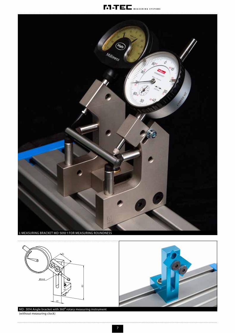
(without measuring clock)MD - 3014 Angle bracket with 360⁰ rotary measuring instrument
L-MEASURING BRACKET MD-5010-1 FOR MEASURING ROUNDNESS

8
80
50
14
20
Angular bracket completely optional in aluminium/ steelUse: Partial stopper in conjunction with measuring bolt and measuring gauge | Application on page 27
MD - 3020-0 in aluminium | MD-3020-1 Angular bracket in steel
Use: To fix the test specimen to prevent it from tilting or sliding away by manual rotation (for e.g. in concentricity measurement)
MD - 3012-0 in aluminium | MD-3012-1 in steel | Swivel arm with clutch
TOOTH-DEPTH MEASUREMENT WITH CONCENTRICITY TESTER BG-1020
Clampingnut

9
27
stroke min. 160mm
250
Linear device | continuous clamping of the moving slider, also vertically applicable | for usage description see page 27MD - 5041-0 centering linear guides in aluminium
Use: To test the concentricity of components with different diameters (Center of the test specimens is always the same)MD - 4025-0 in 2 mm Stainless steel and aluminium support for 2-40 mm diameter prism holder
SCHEDULED RUN-OUT MEASUREMENT FROM TWO SIDES | Please see page 27 for description

10
80
2050
80
2050
Use: To measure the test piece between points for acceptance of roundness and concentricityMD - 4010-0 Aluminium spring suspended centering tip
Use: To measure the test piece between points for acceptance of roundness and concentricity/ centering tip Ø 8mmMD - 4000-0 Aluminium centering tip (fixed)
DIAMETER AND RUN-OUT MEASUREMENT WITH ELECTRONIC SENSORS

11
Use: Measuring acceptance of large and heavy test pieces with center distance less than Ø 125mm. Continuously adjustable contact pressure. Centering tips in special sizes possible
Use: Measuring acceptance of large and heavy test pieces with center distance less than Ø 125mm. Continuously adjustable contact pressure. Centering tips in special sizes possible
MD - 4015-0 in Gray cast iron/ Tailstock with fixed centering tip Ø 16mm
MD - 4016 in Gray cast iron/ Tailstock spring supported
SCHEMATIC ASSEMBLY OF TAILSTOCK MD-4015 WITH SUPPORT KM-4015-6 ON BASE PROFILE MD-2000-0 FOR TWO HEIGHTS (60MM AND 100MM)

12
130
7012
30
Use: To measure diameter and radial run-outMD - 5000-0 in aluminium/ MD-5000-1 in steel | Measuring clamp U-profile for Ø 6-50mm
Use: To measure diameter and radial run-out of larger sizesMD - 5000-2 in steel | Measuring clamp U-profile for Ø 50-100mm
MEASUREMENT OF DIAMETER AND RUN-OUT IN A SINGLE DEVICE | COMPONENT Ø 90MM

13
80
30
7012
130
2030
74
90
Use: To measure concentricity errors below 135⁰ for e.g. determination of polygonal or tension errorMD - 5010-0 in aluminium | MD-5010-1 in steel | Measuring clamp L-profile
Use: Several diameter and groove measurements in one spindle/ for usage description please see page 24 - 26MD - 5020-0 in aluminium | MD-5020-1 in steel | Pendulum holder Ø 6-50mm
ADJUSTMENT OF PENDULUM HOLDER MD-5020-1
2 | ADJUSTING SCREW WITH COMPRESSION SPRING FOR ADJUSTMENT OF THE PRESSING FORCE
3 | MOUNTING AND CLAMPING OF THE PENDULUM HOLDER FOR HEIGHT ADJUSTMENT
1 | PIVOT POINT OF THE HOLDER

14

15
MULTI-POSITION MEASUREMENT OF ONE SPINDLE WITH 5 DIAMETERS AND THE TOTAL LENGTH

16
74
For diameters
between
Ø 1-40 mm
70
30
12
MD - 4031-0 Concentricity measuring device with O-Ring mounted bearing
RADIAL RUN-OUT MEASUREMENT OF A TEST PIECE
Continuously adjustable clamping bracket with run-out accuracy 0.003 mm
MD - 4020 in aluminium | MD-4020-1 auxiliary support in steel
17
100
Measuring range 24-83 mm
According to gauge slides
Hub: 60mm
100
24
24
22 30
80
66
12
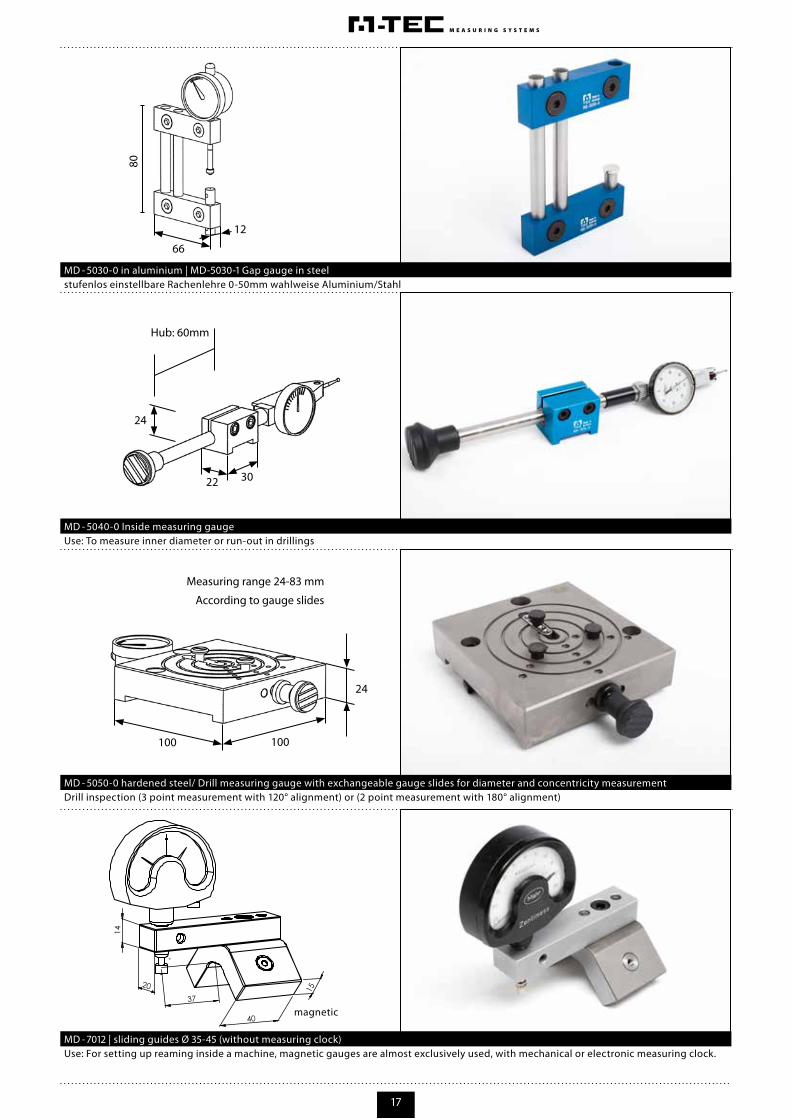
Use: To measure inner diameter or run-out in drillings
Drill inspection (3 point measurement with 120° alignment) or (2 point measurement with 180° alignment)
Use: For setting up reaming inside a machine, magnetic gauges are almost exclusively used, with mechanical or electronic measuring clock.
magnetic
MD - 5040-0 Inside measuring gauge
MD - 5050-0 hardened steel/ Drill measuring gauge with exchangeable gauge slides for diameter and concentricity measurement
MD - 7012 | sliding guides Ø 35-45 (without measuring clock)
stufenlos einstellbare Rachenlehre 0-50mm wahlweise Aluminium/StahlMD - 5030-0 in aluminium | MD-5030-1 Gap gauge in steel
18
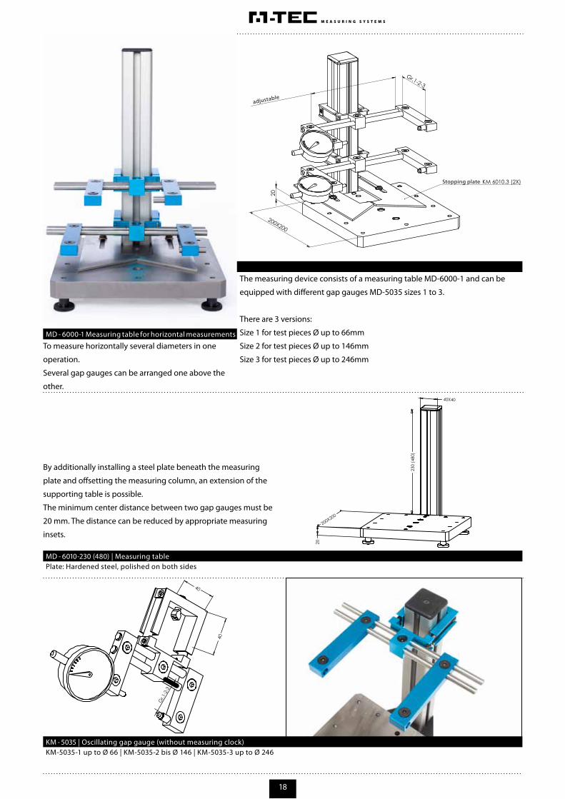
To measure horizontally several diameters in one
operation.
Several gap gauges can be arranged one above the
other.
The measuring device consists of a measuring table MD-6000-1 and can be
equipped with different gap gauges MD-5035 sizes 1 to 3.
There are 3 versions:
Size 1 for test pieces Ø up to 66mm
Size 2 for test pieces Ø up to 146mm
Size 3 for test pieces Ø up to 246mm
By additionally installing a steel plate beneath the measuring
plate and offsetting the measuring column, an extension of the
supporting table is possible.
The minimum center distance between two gap gauges must be
20 mm. The distance can be reduced by appropriate measuring
insets.
MD - 6000-1 Measuring table for horizontal measurements
KM-5035-1 up to Ø 66 | KM-5035-2 bis Ø 146 | KM-5035-3 up to Ø 246
Plate: Hardened steel, polished on both sides
KM - 5035 | Oscillating gap gauge (without measuring clock)
MD - 6010-230 (480) | Measuring table
adjustable
Stopping plate

19
Differential measuring tableMD - 6000-5
Sum-differential- measuring table with 2 electronic measuring sensors
20
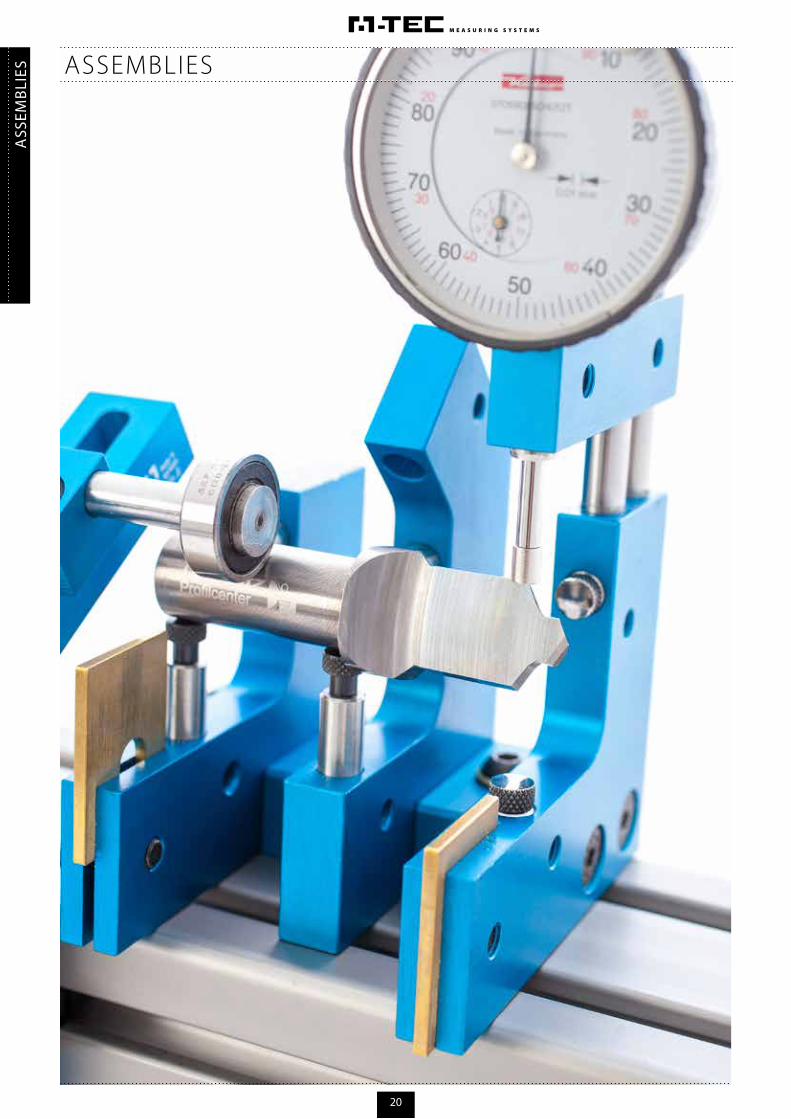
ASS
EMBL
IES ASSEMBLIES

21
The workpiece is clamped between 3 rollers and rolled without center.
By turning the handwheel, the component is brought into rotation.
Run-out test from 1mm to 40 mm is possible.
Run-out error 0.003mm
Measuring clock- mounting hole ∅ 8mm
Granite plate made of natural hard rock of the
highest quality and hardness. Measuring
column can contain any number of adjustable
swivel arms. Measurement area can be fully
utilized by the adjustable swivel arms. Slightly
adjustable in height and side.
Measuring table 200X200mm
Measuring column length 250mm or 500 mm
(optional in Al. or Granite)
Measuring clock mounting hole ∅ 8mm
Testing of run-out from outside, inside and flat surfaces
Swivel arm for runout measuring device
MD - 3011
Run-out measuring device
Extension MD - 3010
2X Universal swivel arm
Basic profile
KM - 1010
MD-3010
MD - 4031MD - 2000
BG - 1010
BG - 1020
CONCENTRICITY TESTING
MULTI-FUNCTION MEASURING TABLE
BG - 1020
BG - 1010
Measuring heights and distances

22
All components will be delivered with mounting material. For Al., granite and steel variants, see price list.
HOLDER FOR GAP GAUGE FOR MEASUREMENT OF SMALL PARTS
INDIVIDUAL PARTS
KM - 1020
KM - 1023
KM - 1047 KM - 5031-1KM - 4015-6
Distance plate
Support plate 2X
Support boltcut form
Gap gauge holderSupport 40 mm for tailstock MD-4015 (tip height 100 mm)
KM - 1021
KM - 1019Measuring ∅ 50mm
Centering point 2X
KM - 1046
KM - 1045Subject to freeassembly ofangle bracket
Support-stopperbolt with threadsize M2.5 4X
KM - 1013
KM - 1017Measuring ∅ 100mm
Gauging instrumentholder 90° 4X
KM - 1007
KM - 1010
KM - 1006Gauging instrument holder, rotatable 360° 4X
Extension ofuniversal swivel arm
Gauging instrumentholder parallel 4X
IND
IVID
UA
L PA
RTS
23
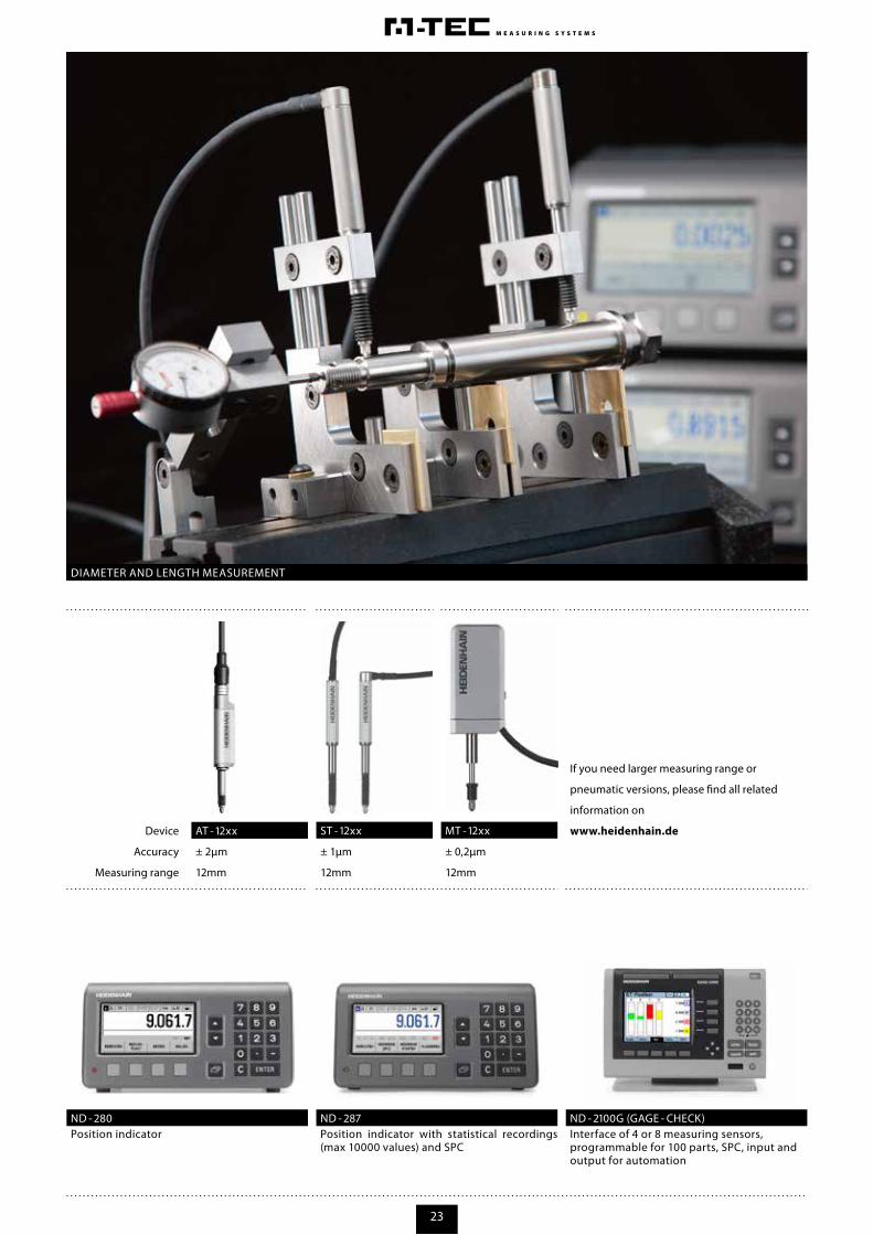
Position indicator with statistical recordings (max 10000 values) and SPC
Interface of 4 or 8 measuring sensors, programmable for 100 parts, SPC, input andoutput for automation
Position indicator
Device
Accuracy
Measuring range
± 2µm
12mm
± 1µm
12mm
± 0,2µm
12mm
If you need larger measuring range or
pneumatic versions, please find all related
information on
www.heidenhain.de
DIAMETER AND LENGTH MEASUREMENT
ND - 280 ND - 2100G (GAGE - CHECK)ND - 287
ST - 12xxAT - 12xx MT - 12xx

24
With this further sliding, the test piece reaches the highest point. The test piece will have reached the bottom stopper and, when
retracted, will show the highest point on the display gauge.
Slide the
test piece
further in
Place the test piece on the support plate and slide in on the
U-bracket
Slide in the
test piece
1
2 3
With display measuring devices (e.g. measuring
clock), naturally Ø of the highest point is
determined.
The measurement and adjustment of the master
piece is carried out in 3 steps
The adjustable brass plate (support) on the
measuring brackets U-Profile and LProfile help in
pre-positioning and protecting the work piece.
ADJUST DIAMETER AND TEST WITH DISPLAY MEASURING DEVICES IN U-BRACKET
INST
RUC
TIO
NS
FOR
USE

25
RUN-OUT MEASUREMENT OF A THREADED SHAFT, Ø 3MM AT SUPPORT POINTS

26
12
3
4
56
7
8
3 | CLAMPING SCREW AND ADJUSTABLE BOTTOM STOPPER FOR TEST PIECE
7 | CLAMPING SCREW TO FIX THE U-BRACKET ON THE BASE PROFILE
8 | CLAMPING SCREW FOR SMOOTH ADJUSTMENT OF INCLINATION OF THE BASE PROFILE
There are 2 variants from Ø 6-50mm and from Ø 50-100mm
For the correct setting of the U-bracket,please proceed as follows:
The center distance of U-bracket MD-5000 (from Ø 6-50mm) is 60mm
The center distance of U-bracket MD-1-5000 (from Ø 50-100mm) is 100mm
Mounting distance for bottom stopper = Grundabstand – (D/2) - 1mme.g. 54mm = 100mm – (90mm / 2) - 1mm
Mounting distance for supporting bolt = Center distance – (D/2)e.g. 55mm = 100mm – (90mm / 2)
4 | THE DOWEL PIN OF MD-5000 IS CYLINDRICAL WITH Ø 8MM OF MD-1-5000 A THREADED BOLT OF SIZE M8
1 | CLAMPING SCREW FOR HEIGHT ADJUSTMENT
2 | CLAMPING SCREW FOR MEASURING DEVICE
5 | CLAMPING SCREW FOR SUPPORTING BOLT
6 | SUPPORT PLATE FOR PRE-POSITIONING OF THE TEST PIECE
D=90mm
Center distance
Center distance
Mounting distance
for supporting bolt
D/2Mounting distance
of bottom stopper
DESCRIPTION: U-BRACKET

27
The linear guide is a portable element and serves to support the measuring equipment or other modules for tight installation situations
1 | PLACE THE TEST SPECIMEN AND HOLD IT BETWEEN CENTERING POINTS
2 | ROTATE THE TEST SPECIMEN >360° AND DETERMINE OVERALL RADIAL RUN-OUT
EXAMPLE: SCHEDULED RUN-OUT MEASUREMENT FROM TWO SIDES

M-Tec Measuring systems
Ohmstraße 9
91161 Hilpoltstein
Telefon 0 91 74 9 77 97-20
Telefax 0 91 74 9 77 97-30
www.m-tec-messsysteme.com
Fotos und Gestaltung: Oliver Frank Kommunikationsdesign HilpoltsteinStand: 04/12 Änderungen vorbehalten