c:\users\josemaria\documents\tfg\5. autocad\projecte etseib
TRANSCRIPT


ETSEIB - UPC
Josep Mª Mabres Anter
Design Calculations
TFG 2016-06-01
ETSEIB - UPC
Josep Mª Mabres Anter
Design Calculations
TFG 2016-06-01
AutoPIPE Vessel (Microprotol) procal V33.1.0.11 2 prodia2 V33.1.0.11 Bentley Systems, Inc.
Table of Contents
Table of Contents ................................................................................................................................................................ 2
Codes, Guidelines and Standards Implemented. .............................................................................................................. 4
Design Conditions. .............................................................................................................................................................. 5
Allowable stresses and safety factors ................................................................................................................................. 6
Shell (comp. 1) .................................................................................................................................................................. 6
Tube (comp. 2) .................................................................................................................................................................. 6
Test Pressure ....................................................................................................................................................................... 7
Tube layout. ......................................................................................................................................................................... 8
Tube layout report. ............................................................................................................................................................ 9
flow section. .....................................................................................................................................................................10
Pass Partition Plate. ........................................................................................................................................................11
Element(s) of geometry in internal pressure ....................................................................................................................12
Korbbogen Type Head (30.10) Internal pressure. ...........................................................................................................12
Conical shell (30.24) internal pressure. ...........................................................................................................................13
Korbbogen Type Head (25.12) Internal pressure. ...........................................................................................................14
Cylindrical shell under internal pressure. .......................................................................................................................15
Body flange(s) and cover(s) ...............................................................................................................................................16
Body Flange and Cover 25.01 in operation. ....................................................................................................................16
Body Flange and Cover 30.03 in operation. ....................................................................................................................18
Body Flange and Cover 25.01 in test. ..............................................................................................................................20
Body Flange and Cover 30.03 in test. ..............................................................................................................................21
Body Flange and Cover 3903 in test. ...............................................................................................................................22
Tubesheet(s) and Expansion Joint ....................................................................................................................................23
Tubesheet, Loading conditions 1 [corroded normal condition] AD 2000-Merkblatt B 5, 07.2012. ................................23
Tubesheet, Loading conditions 2 [corroded normal condition] AD 2000-Merkblatt B 5, 07.2012. ................................25
Tubesheet, Loading conditions 3 [corroded normal condition] AD 2000-Merkblatt B 5, 07.2012. ................................27
Tubesheet, Loading conditions T0 [test condition] AD 2000-Merkblatt B 5, 07.2012. ...................................................29
Tubesheet, Loading conditions 0T [test condition] AD 2000-Merkblatt B 5, 07.2012. ...................................................31
Tubes of the bundle. ...........................................................................................................................................................33
Tube of bundle in internal pressure. ................................................................................................................................33
Tube of bundle in external pressure. ................................................................................................................................33
Vessel under combination loading ....................................................................................................................................34
Model for stress analysis due to supporting. ....................................................................................................................34
Location of dominant stresses and worst cases. ...............................................................................................................35
Case 1 - Operation Int.Max.P. (Corroded Weight) . ........................................................................................................36
Maximum Allowable Working Pressure ..........................................................................................................................40
Maximum Allowable Working Pressure(Geometry). .......................................................................................................40
Maximum Allowable Working Pressure (Nozzles). ..........................................................................................................40
Maximum Allowable Working Pressure (tubes of bundle). ..............................................................................................41
Maximum Allowable Working Pressure (compartment). .................................................................................................41
Isolated Opening(s) ............................................................................................................................................................42
Isolated opening S2 [ in operation Int.P. ] (Shell Outlet) ............................................................................................42
Isolated opening S2 [ in test Int.P. ] (Shell Outlet) ......................................................................................................43
Isolated opening S1 [ in operation Int.P. ] (Shell Outlet) ............................................................................................44
Isolated opening S1 [ in test Int.P. ] (Shell Outlet) ......................................................................................................45
Isolated opening T2 [ in operation Int.P. ] (Channel Outlet) ......................................................................................46
Isolated opening T2 [ in test Int.P. ] (Channel Outlet) ................................................................................................47
Isolated opening T1 [ in operation Int.P. ] (Channel inlet) .........................................................................................48
Isolated opening T1 [ in test Int.P. ] (Channel inlet) ...................................................................................................49
Summary .............................................................................................................................................................................50
Summary of nozzles [ Location and Dimensions ]. ..........................................................................................................50
ETSEIB - UPC
Josep Mª Mabres Anter
Design Calculations
TFG 2016-06-01
AutoPIPE Vessel (Microprotol) procal V33.1.0.11 3 prodia2 V33.1.0.11 Bentley Systems, Inc.
Summary of nozzles [ Type, Adjacent Openings, Goose and Material ]. .........................................................................50
Summary of nozzles [ Type, Weight and Local Loads ]. ..................................................................................................50
Summaries of bundle. .......................................................................................................................................................51
Summary of Forged Items and Relevant Accessories. ......................................................................................................52
Summary of Geometry. .....................................................................................................................................................53
Summary of Weights, Capacities and Painting Areas. .....................................................................................................54
Summary of saddles..........................................................................................................................................................55
Summary of Foundation Loads ........................................................................................................................................55
ETSEIB - UPC
Josep Mª Mabres Anter
Design Calculations
TFG 2016-06-01
AutoPIPE Vessel (Microprotol) procal V33.1.0.11 4 prodia2 V33.1.0.11 Bentley Systems, Inc.
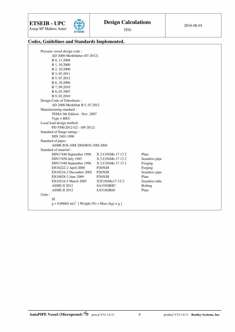
Codes, Guidelines and Standards Implemented.
Pressure vessel design code :
AD 2000-Merkblätter (07-2012)
B 0, 11.2008
B 1, 10.2000
B 2, 10.2000
B 3, 05.2011
B 5, 07.2012
B 6, 10.2006
B 7, 09.2010
B 8, 05.2007
B 9, 02.2010
Design Code of Tubesheets :
AD 2000-Merkblatt B 5, 07.2012
Manufacturing standard :
TEMA 9th Edition - Nov. 2007
Type = BKU
Local load design method:
PD 5500:2012 G2 - (09-2012)
Standard of flange ratings :
DIN 2401:1996
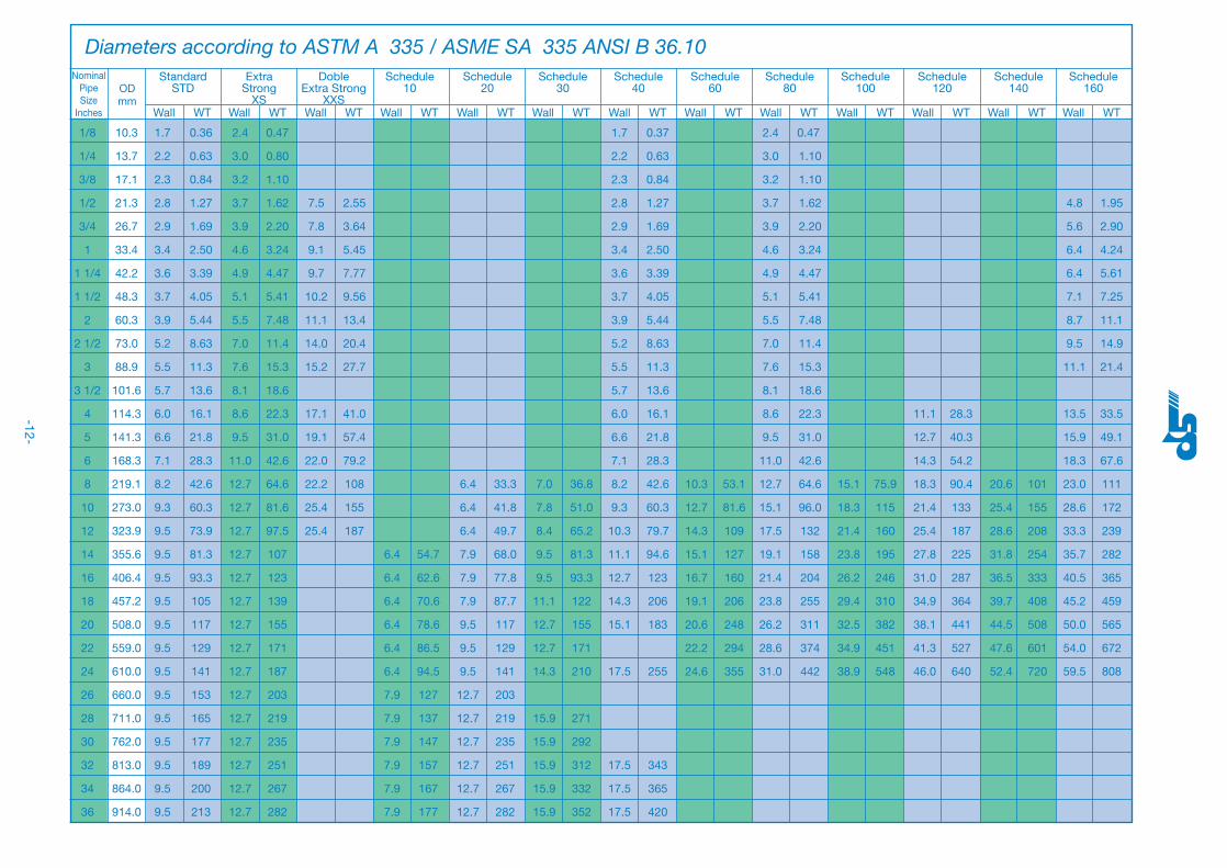
Standard of pipes:
ASME B36.10M-2004/B36.19M-2004
Standard of material :
DIN17440 September 1996 X 2 CrNiMo 17 13 2 Plate
DIN17458 July 1985 X 2 CrNiMo 17 13 2 Seamless pipe
DIN17440 September 1996 X 2 CrNiMo 17 13 2 Forging
EN10222-2 April 2000 P265GH Forging
EN10216-2 December 2002 P265GH Seamless pipe
EN10028-2 June 2009 P265GH Plate
EN10216-5 March 2005 X2CrNiMo17-12-2 Seamless tube
ASME II 2012 SA193GRB7 Bolting
ASME II 2012 SA516GR60 Plate
Units :
SI
g = 9,80665 m/s2 [ Weight (N) = Mass (kg) × g ]

ETSEIB - UPC
Josep Mª Mabres Anter
Design Calculations
TFG 2016-06-01
AutoPIPE Vessel (Microprotol) procal V33.1.0.11 5 prodia2 V33.1.0.11 Bentley Systems, Inc.
Design Conditions. Shell (comp. 1) Tube (comp. 2) /
Internal pressure : 0,8 MPa 1,2 MPa /
Requested MAWP : 0,8 MPa 1,2 MPa /
Design Temperature : 104,4 °C 260 °C /
Height of liquid : 0 mm 0 mm /
Operating fluid spec. gravity : 1 1 /
Corrosion : 0 mm 3,175 mm /
External pressure : /
Design temp., external : /
Test Pressure : /
Test fluid spec. gravity : 1 1 /
Insulation Thickness : 0 mm 0 mm /
Weight/density of insulation : 35 kg/m3 35 kg/m3 /
Construction Category : /
Nominal stress : 1 1 /

ETSEIB - UPC
Josep Mª Mabres Anter
Design Calculations
TFG 2016-06-01
AutoPIPE Vessel (Microprotol) procal V33.1.0.11 6 prodia2 V33.1.0.11 Bentley Systems, Inc.
Allowable stresses and safety factors
AD B0 / AD B6
f Allowable stress at design temperature.
Rm tensile strength.
Rp0.2 yield strength 0,2 %.
Rp1 yield strength 1 %.
R Average stress to cause rupture at the end of 100000 hours at design temperature.
Flanges
in operation f = f 1
In test and gasket seating f = f 1
Shell (comp. 1) Allowable stress at design temperature f
Materials Normal Conditions Exceptional and test
conditions Creep
Excluding bolting B0 B6 B0 B6 B0 B6
Carbon steel Rp0.2 / 1,5 Rp0.2 / 1,6 Rp0.2 / 1,05 Rp0.2 / 1,1 R / 1,5 R / 1,6
Stainless steel Rp1 / 1,5 Rp1 / 1,6 Rp1 / 1,05 Rp1 / 1,1 R / 1,5 R / 1,6
Copper alloy Rm / 3,5 Rm / 4 Rm / 2,5 Rm / 2,5 R / 3,5 R / 4
Aluminum Alloy Rp1 / 1,5 Rp1 / 1,6 Rp1 / 1,05 Rp1 / 1,1 R / 1,5 R / 1,6
Nickel alloy Rp0.2 / 1,5 Rp0.2 / 1,6 Rp0.2 / 1,05 Rp0.2 / 1,1 R / 1,5 R / 1,6
Titanium and Zirconium Rp0.2 / 1,5 Rp0.2 / 1,6 Rp0.2 / 1,05 Rp0.2 / 1,1 R / 1,5 R / 1,6
Cast Iron Rp0.2 / 2 Rp0.2 / 2 Rp0.2 / 1,4 Rp0.2 / 1,5 R / 2 R / 2
Bolting Standard Neckdown Standard Neckdown Standard Neckdown
Carbon steel Rp0.2 / 1,8 Rp0.2 / 1,5 Rp0.2 / 1,3 Rp0.2 / 1,1 R / 1,8 R / 1,5
Stainless steel Rp1 / 1,8 Rp1 / 1,5 Rp1 / 1,3 Rp1 / 1,1 R / 1,8 R / 1,5
Tube (comp. 2) Allowable stress at design temperature f
Materials Normal Conditions Exceptional and test
conditions Creep
Excluding bolting B0 B6 B0 B6 B0 B6
Carbon steel Rp0.2 / 1,5 Rp0.2 / 1,6 Rp0.2 / 1,05 Rp0.2 / 1,1 R / 1,5 R / 1,6
Stainless steel Rp1 / 1,5 Rp1 / 1,6 Rp1 / 1,05 Rp1 / 1,1 R / 1,5 R / 1,6
Copper alloy Rm / 3,5 Rm / 4 Rm / 2,5 Rm / 2,5 R / 3,5 R / 4
Aluminum Alloy Rp1 / 1,5 Rp1 / 1,6 Rp1 / 1,05 Rp1 / 1,1 R / 1,5 R / 1,6
Nickel alloy Rp0.2 / 1,5 Rp0.2 / 1,6 Rp0.2 / 1,05 Rp0.2 / 1,1 R / 1,5 R / 1,6
Titanium and Zirconium Rp0.2 / 1,5 Rp0.2 / 1,6 Rp0.2 / 1,05 Rp0.2 / 1,1 R / 1,5 R / 1,6
Cast Iron Rp0.2 / 2 Rp0.2 / 2 Rp0.2 / 1,4 Rp0.2 / 1,5 R / 2 R / 2
Bolting Standard Neckdown Standard Neckdown Standard Neckdown
Carbon steel Rp0.2 / 1,8 Rp0.2 / 1,5 Rp0.2 / 1,3 Rp0.2 / 1,1 R / 1,8 R / 1,5
Stainless steel Rp1 / 1,8 Rp1 / 1,5 Rp1 / 1,3 Rp1 / 1,1 R / 1,8 R / 1,5
ETSEIB - UPC
Josep Mª Mabres Anter
Design Calculations
TFG 2016-06-01
AutoPIPE Vessel (Microprotol) procal V33.1.0.11 7 prodia2 V33.1.0.11 Bentley Systems, Inc.
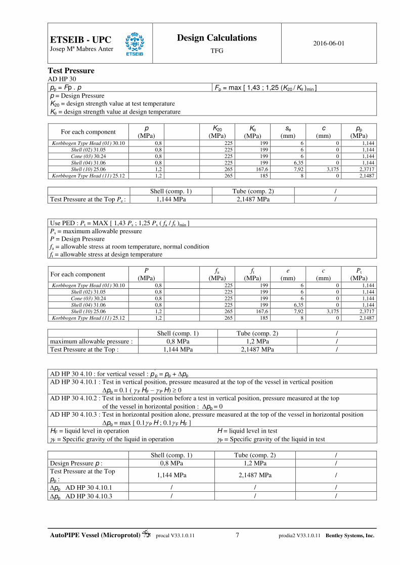
Test Pressure AD HP 30
pp = Fp . p Fp = max [ 1,43 ; 1,25 (K20 / K)min ]
p = Design Pressure K20 = design strength value at test temperature
K = design strength value at design temperature
For each component p
(MPa)
K20
(MPa) K
(MPa) se
(mm) c
(mm) pp
(MPa) Korbbogen Type Head (01) 30.10 0,8 225 199 6 0 1,144
Shell (02) 31.05 0,8 225 199 6 0 1,144
Cone (03) 30.24 0,8 225 199 6 0 1,144
Shell (04) 31.06 0,8 225 199 6,35 0 1,144
Shell (10) 25.06 1,2 265 167,6 7,92 3,175 2,3717
Korbbogen Type Head (11) 25.12 1,2 265 185 8 0 2,1487
Shell (comp. 1) Tube (comp. 2) /
Test Pressure at the Top Pe : 1,144 MPa 2,1487 MPa /
Use PED : Pt = MAX [ 1,43 Ps ; 1,25 Ps ( fa / ft )min ]
Ps = maximum allowable pressure P = Design Pressure fa = allowable stress at room temperature, normal condition ft = allowable stress at design temperature
For each component P
(MPa)
fa
(MPa) ft
(MPa) e
(mm) c
(mm) Pt
(MPa) Korbbogen Type Head (01) 30.10 0,8 225 199 6 0 1,144
Shell (02) 31.05 0,8 225 199 6 0 1,144
Cone (03) 30.24 0,8 225 199 6 0 1,144
Shell (04) 31.06 0,8 225 199 6,35 0 1,144
Shell (10) 25.06 1,2 265 167,6 7,92 3,175 2,3717
Korbbogen Type Head (11) 25.12 1,2 265 185 8 0 2,1487
Shell (comp. 1) Tube (comp. 2) /
maximum allowable pressure : 0,8 MPa 1,2 MPa /
Test Pressure at the Top : 1,144 MPa 2,1487 MPa /
AD HP 30 4.10 : for vertical vessel : p’p = pp + pp
AD HP 30 4.10.1 : Test in vertical position, pressure measured at the top of the vessel in vertical position
pp = 0.1 ( F HF – P H) 0
AD HP 30 4.10.2 : Test in horizontal position before a test in vertical position, pressure measured at the top
of the vessel in horizontal position :pp = 0
AD HP 30 4.10.3 : Test in horizontal position alone, pressure measured at the top of the vessel in horizontal position
pp = max [ 0.1 P H ; 0.1 F HF ]
HF = liquid level in operation H = liquid level in test
F = Specific gravity of the liquid in operation P = Specific gravity of the liquid in test
Shell (comp. 1) Tube (comp. 2) /
Design Pressure p : 0,8 MPa 1,2 MPa /
Test Pressure at the Top
pp : 1,144 MPa 2,1487 MPa /
pp AD HP 30 4.10.1 / / /
pp AD HP 30 4.10.3 / / /
ETSEIB - UPC
Josep Mª Mabres Anter
Design Calculations
TFG 2016-06-01
AutoPIPE Vessel (Microprotol) procal V33.1.0.11 8 prodia2 V33.1.0.11 Bentley Systems, Inc.
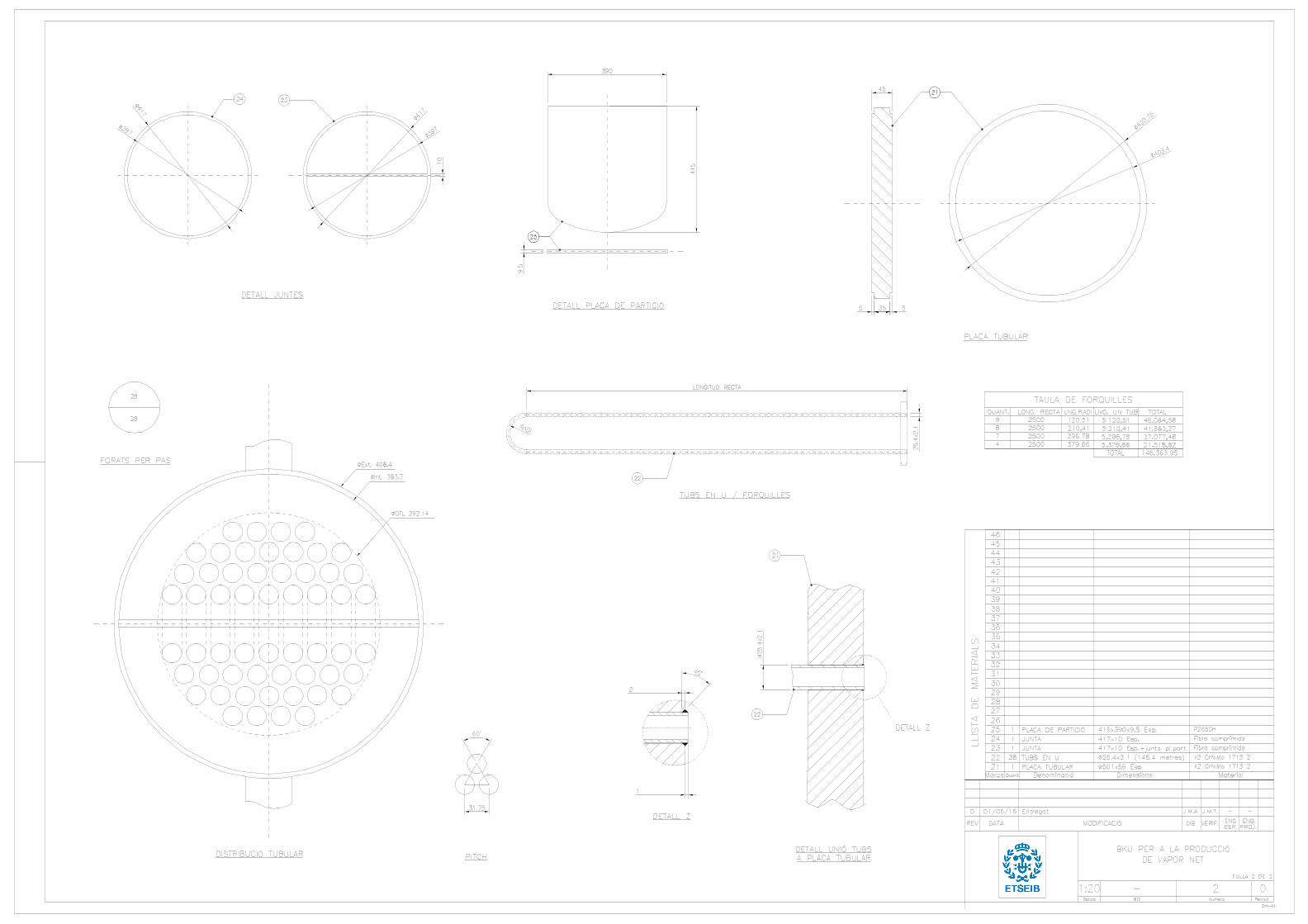
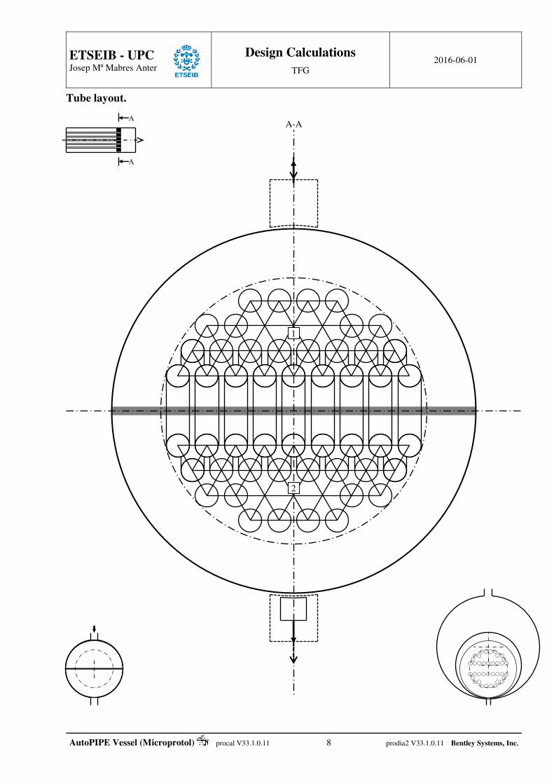
Tube layout.
A-A
1
2
A
A

ETSEIB - UPC
Josep Mª Mabres Anter
Design Calculations
TFG 2016-06-01
AutoPIPE Vessel (Microprotol) procal V33.1.0.11 9 prodia2 V33.1.0.11 Bentley Systems, Inc.
Tube layout report.
Shell inside diameter : 399,65 mm Outer tube limit diameter 292,14 mm Baffle Outside Diameter : 396,48 mm Tube Pitch : 31,75 mm Tube Diameter : 25,4 mm Number of Tubes : 56 Mean Deviation : 0 % Number of Tie Rods : 0 Variance Factor : 0 % Number of sealing strips : 0 Mean tolerance : 0 % Number of Sealing Rods : 0 Max. pass tolerance : 0 % Number of sliding rails : 0 Actual shell inlet free height : 0 mm Actual shell outlet free height : 65,84 mm
Pass number Number of Tubes Adj. Tol. Adj. Tol.
1 2
28 28
Tol. 1-2 : 0,00 %
No. of support plates = 0 Type no.. flow section
No. of baffles (Support Plate) = 0 / / /
Unsupported tube spans (calculated values) :
between two Tubesheets (both ends fixed) = / between a Tubesheet and a tube support (one end fixed, the other pinned) = 0 mm between two tube supports (both ends pinned) = 0 mm
Unsupported tube spans (fixed value) :
between a Tubesheet and a tube support (one end fixed, the other pinned) = /

ETSEIB - UPC
Josep Mª Mabres Anter
Design Calculations
TFG 2016-06-01
AutoPIPE Vessel (Microprotol) procal V33.1.0.11 10 prodia2 V33.1.0.11 Bentley Systems, Inc.
flow section. Minimum inside depth of channels.
The minimum cross-over area for flow between successive tube passes is at least equal to 1.3 times the flow area through the tubes of one pass. Channel inlet : 0 ≤ 319 mm Channel outlet (or rear box) : / (for a floating head , it’s the length of flange under the crown)
TEMA RGP-RCB-4.62 Shell or Bundle Entrance and Exit Areas.
Outer tube limit diameter : OTL = 292,14 mm Tube Pitch : Pt = 31,75 mm Factor indicating tube pitch type and orientation : F2 = 0,866
Tube outside diameter : Dt = 25,4 mm
Impingement plate length : Lp = 0 mm Impingement plate edge length : Ip = 0 mm
Fluid velocity Inlet Outlet
flow section area (nozzle) : V2n = 0 Jm3 0 Jm3
flow section area (shell cross section) : V2s = 0 Jm3 0 Jm3
flow section area (bundle) : V2b = 0 Jm3 0 Jm3
Shell inside diameter : Ds = 399,65 mm 399,65 mm Nozzle internal diameter : Dn = 0 mm 54,76 mm
RGP-RCB-4.621 + 4.622 Shell entrance or exit area Inlet Outlet
Factor indicating presence of impingement plate : F1 = 1 1 Free height at nozzle centerline : h1 = 0 mm 65,84 mm Free height at nozzle edge : h2 = h1-0.5[Ds-(Ds
2-Dn2)0.5] = 0 mm 63,95 mm
Average free height above tube bundle or impingement plate : h = 0.5(h1+h2) = 0 mm 64,89 mm
Requested : As,min = 2
22
4 n
sn
V
VD
= 0 mm2 2.355,1 mm2
calculated : As =
t
ttnn
PF
DPDFhD
2
2
14
= 0 mm2 11.707,8 mm2
Required free height at nozzle centerline : h1,min = 0 mm 11,47 mm
RGP-RCB-4.623 4.624 Bundle entrance or exit area Inlet Outlet
Effective chord distance across bundle : K = Area of Impingement Plate : Ap = Unrestricted longitudinal flow area : Al = Distance 1st Baffle : Bs =
Requested : Ab,min = 2
22
4 n
bn
V
VD
=
calculated : Ab = l
t
ttpsss A
PF
DPAKBOTLDB
2
=
Required baffle spacing : Bs,min =

ETSEIB - UPC
Josep Mª Mabres Anter
Design Calculations
TFG 2016-06-01
AutoPIPE Vessel (Microprotol) procal V33.1.0.11 11 prodia2 V33.1.0.11 Bentley Systems, Inc.
Pass Partition Plate. TEMA RCB-9.13.
Material : SA516GR60 Nominal thickness : tn = 9,5 mm Temperature : 260 °C Corrosion : RCB-1.518 Allowable stress : S = 120 MPa Pressure drop across plate : q = 0 MPa
RCB-9.132 : S
qBbt
5.1
Factor B Fixing
Table RCB-9.132 1 = Three sides fixed, one side simply supported
2 = Long sides fixed, short sides simply supported
tmin : Table RCB-9.131 (Carbon Steel)
3 = Short sides fixed, long sides simply supported
Roark’s Formulas 4 = semicircular plate, all edges fixed
RCB-9.133 : The plate shall be attached with fillet welds on each sides with a minimum leg of tleg = ¾ t.
Front Pass Partition Plate.
Fixing a (mm) b (mm) a/b B tmin (mm) t (mm) tleg (mm)
1 390,56 421,61 0,93 0,2675 9,50 0,00 0,00
treq = max [ max(t) ; max(tmin) ] = 9,5 mm The pass partition plate thickness is adequate.
ETSEIB - UPC
Josep Mª Mabres Anter
Design Calculations
TFG 2016-06-01
AutoPIPE Vessel (Microprotol) procal V33.1.0.11 12 prodia2 V33.1.0.11 Bentley Systems, Inc.
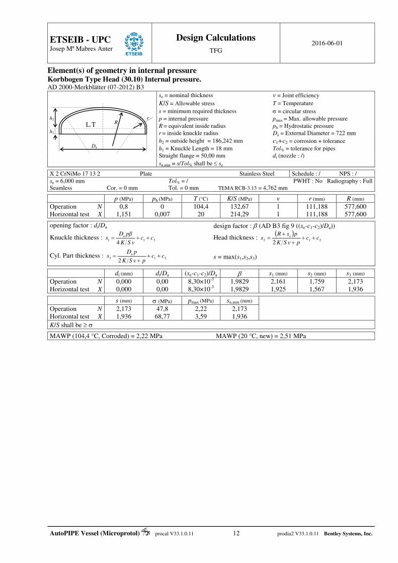
Element(s) of geometry in internal pressure Korbbogen Type Head (30.10) Internal pressure. AD 2000-Merkblätter (07-2012) B3 se = nominal thickness v = Joint efficiency
K/S = Allowable stress T = Temperature
s = minimum required thickness = circular stress
p = internal pressure pmax = Max. allowable pressure
R = equivalent inside radius ph = Hydrostatic pressure
r = inside knuckle radius Da = External Diameter = 722 mm
h2 = outside height = 186,242 mm c1+c2 = corrosion + tolerance
h1 = Knuckle Length = 18 mm Tol% = tolerance for pipes
Straight flange = 50,00 mm di (nozzle : /)
sn,min = s/Tol% shall be se X 2 CrNiMo 17 13 2 Plate Stainless Steel Schedule : / NPS : /
se = 6,000 mm Tol% = / PWHT : No Radiography : Full Seamless Cor. = 0 mm Tol. = 0 mm TEMA RCB-3.13 = 4,762 mm
p (MPa) ph (MPa) T (°C) K/S (MPa) v r (mm) R (mm)
Operation N Horizontal test X
0,8 1,151
0 0,007
104,4 20
132,67 214,29
1 1
111,188 111,188
577,600 577,600
opening factor : di/Da design factor : (AD B3 fig 9 ((se-c1-c2)/Da))
Knuckle thickness : 21a
14
ccvSK
pβDs Head thickness :
21
e2
2cc
pvSK
psRs
Cyl. Part thickness : 21a
32
ccpvSK
pDs
s = max(s1,s2,s3)
di (mm) di/Da (se-c1-c2)/Da s1 (mm) s2 (mm) s3 (mm)
Operation N Horizontal test X
0,000 0,000
0,00 0,00
8,30×10⁻³ 8,30×10⁻³
1,9829 1,9829
2,161 1,925
1,759 1,567
2,173 1,936
s (mm) (MPa) pmax (MPa) sn,min (mm)
Operation N Horizontal test X
2,173 1,936
47,8 68,77
2,22 3,59
2,173 1,936
K/S shall be MAWP (104,4 °C, Corroded) = 2,22 MPa MAWP (20 °C, new) = 2,51 MPa
r
L.T
Da
R
h1
h2

ETSEIB - UPC
Josep Mª Mabres Anter
Design Calculations
TFG 2016-06-01
AutoPIPE Vessel (Microprotol) procal V33.1.0.11 13 prodia2 V33.1.0.11 Bentley Systems, Inc.
Conical shell (30.24) internal pressure. AD 2000-Merkblätter (07-2012) B2
sn = nominal thickness = 6,00 mm r = Knuckle radius at large end = 0,00 mm p = internal pressure
= Half angle = 30 ° Flare radius at small end = 0,00 mm K/S = Nominal stress
T = Temperature Da1 = Large end diameter = 710,00 mm v = Joint efficiency
Cone height = 547,85 mm Small end diameter = 393,70 mm c1+c2 = corrosion + tolerance
X 2 CrNiMo 17 13 2 Plate PWHT : No Radiography : 10% Scope of application.
70° 70° 0.001 sc1c2 / Da1 0.1 0.01 r / Da1 0.15 8.1.2 Required thickness of cone.
sg = DK p/(2 K/S vp) (1 / cos)+c1+c2 DK = Da12(sl+r(1cos)+x2sin)
p (MPa) T (°C) K/S (MPa) c1+c2 (mm) v Dk (mm) sg (mm)
Large end Operation Horizontal test
0,8 1,151
104,4 20
132,67 214,29
0,00+0,00 0,00+0,00
0,85 0,85
676,66 678,52
2,78 2,48
Small end Operation Horizontal test
0,8 1,151
104,4 20
132,67 214,29
0,00+0,00 0,00+0,00
0,85 0,85
434,84 433,81
1,79 1,59
MAWP (104,4 °C, Corroded) = 1,81 MPa MAWP (20 °C, new) = 2,05 MPa
8.1.1 large end junction without knuckle.
sl : ( AD B2 Fig. 3.1 3.7 )
21la11 ccsDx
cos7.0 21la12 ccsDx
13 5.0 xx
sl (mm) Da1 (mm) x1(mm) x2(mm) x3 (mm)
Operation N Horizontal test X
3,57 3,32
722,00 722,00
50,78 48,97
38,20 36,83
25,39 24,48
8.1.1 Small end junction.
sl : ( AD B2 Fig. 3.8 )
21la11 ccsDx
cos7.0 21la12 ccsDx
13 5.0 xx
sl (mm) Da1 (mm) x1(mm) x2(mm) x3 (mm)
Operation N Horizontal test X
2,63 2,41
405,70 405,70
32,67 31,28
24,57 23,53
16,33 15,64
x1 x2
Da1
s l
sl
sg
DK
1.4 x2
DK sl
x1
sg
Da1

ETSEIB - UPC
Josep Mª Mabres Anter
Design Calculations
TFG 2016-06-01
AutoPIPE Vessel (Microprotol) procal V33.1.0.11 14 prodia2 V33.1.0.11 Bentley Systems, Inc.
Korbbogen Type Head (25.12) Internal pressure. AD 2000-Merkblätter (07-2012) B3 se = nominal thickness v = Joint efficiency
K/S = Allowable stress T = Temperature
s = minimum required thickness = circular stress
p = internal pressure pmax = Max. allowable pressure
R = equivalent inside radius ph = Hydrostatic pressure
r = inside knuckle radius Da = External Diameter = 406,4 mm
h2 = outside height = 106,542 mm c1+c2 = corrosion + tolerance
h1 = Knuckle Length = 24 mm Tol% = tolerance for pipes
Straight flange = 50,00 mm di (nozzle : /)
sn,min = s/Tol% shall be se P265GH Plate Carbon Steel Schedule : / NPS : /
se = 8,000 mm Tol% = / PWHT : No Radiography : Full Seamless Cor. = 0 mm Tol. = 0 mm TEMA RCB-3.13 = 7,938 mm
p (MPa) ph (MPa) T (°C) K/S (MPa) v r (mm) R (mm)
Operation N Horizontal test X
1,2 2,1525
0 0,0038
260 20
123,33 252,38
1 1
62,586 62,586
325,120 325,120
opening factor : di/Da design factor : (AD B3 fig 9 ((se-c1-c2)/Da))
Knuckle thickness : 21a
14
ccvSK
pβDs Head thickness :
21
e2
2cc
pvSK
psRs
Cyl. Part thickness : 21a
32
ccpvSK
pDs
s = max(s1,s2,s3)
di (mm) di/Da (se-c1-c2)/Da s1 (mm) s2 (mm) s3 (mm)
Operation N Horizontal test X
0,000 0,000
0,00 0,00
1,97×10⁻² 1,97×10⁻²
1,8 1,8
1,779 1,560
1,617 1,418
1,968 1,726
s (mm) (MPa) pmax (MPa) sn,min (mm)
Operation N Horizontal test X
1,968 1,726
29,88 53,6
4,95 10,14
1,968 1,726
K/S shall be MAWP (260 °C, Corroded) = 4,95 MPa MAWP (20 °C, new) = 7,1 MPa
r
L.T
Da
R
h1
h2
ETSEIB - UPC
Josep Mª Mabres Anter
Design Calculations
TFG 2016-06-01
AutoPIPE Vessel (Microprotol) procal V33.1.0.11 15 prodia2 V33.1.0.11 Bentley Systems, Inc.
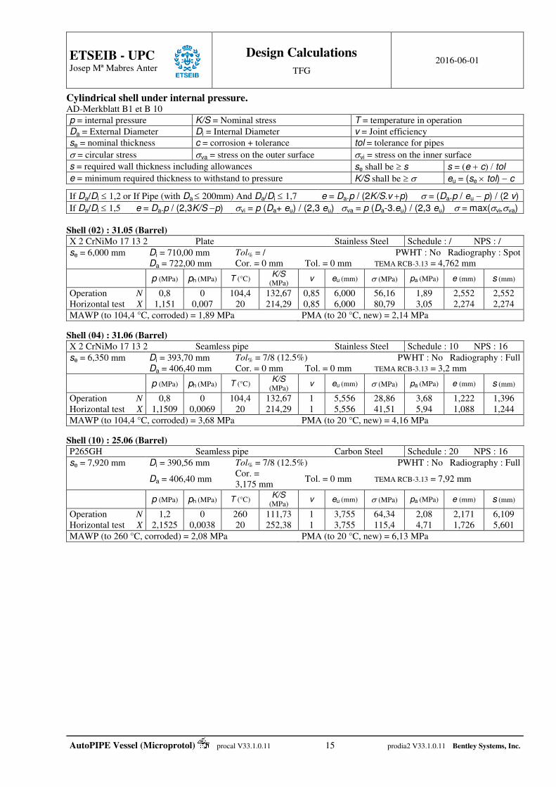
Cylindrical shell under internal pressure. AD-Merkblatt B1 et B 10
p = internal pressure K/S = Nominal stress T = temperature in operation
Da = External Diameter Di = Internal Diameter v = Joint efficiency
se = nominal thickness c = corrosion + tolerance tol = tolerance for pipes
= circular stress va = stress on the outer surface vi = stress on the inner surface
s = required wall thickness including allowances se shall be s s = (e c) tol
e = minimum required thickness to withstand to pressure K/S shall be eu = (se tol) c
If Da/Di 1,2 or If Pipe (with Da 200mm) And Da/Di1,7 e = Da.p / (2K/S.vp) = (Da.p / eu p) / (2 v)
If Da/Di1,5 e = Da.p / (2,3K/Sp) vi = p (Da+ eu) / (2,3 eu) va = p (Da-3.eu) / (2,3 eu) = max(viva)
Shell (02) : 31.05 (Barrel)
X 2 CrNiMo 17 13 2 Plate Stainless Steel Schedule : / NPS : /
se = 6,000 mm Di = 710,00 mm Tol% = / PWHT : No Radiography : Spot Da = 722,00 mm Cor. = 0 mm Tol. = 0 mm TEMA RCB-3.13 = 4,762 mm
p (MPa) ph (MPa) T (°C) K/S (MPa) v eu (mm) (MPa) pa (MPa) e (mm) s (mm)
Operation N Horizontal test X
0,8 1,151
0 0,007
104,4 20
132,67 214,29
0,85 0,85
6,000 6,000
56,16 80,79
1,89 3,05
2,552 2,274
2,552 2,274
MAWP (to 104,4 °C, corroded) = 1,89 MPa PMA (to 20 °C, new) = 2,14 MPa
Shell (04) : 31.06 (Barrel)
X 2 CrNiMo 17 13 2 Seamless pipe Stainless Steel Schedule : 10 NPS : 16
se = 6,350 mm Di = 393,70 mm Tol% = 7/8 (12.5%) PWHT : No Radiography : Full Da = 406,40 mm Cor. = 0 mm Tol. = 0 mm TEMA RCB-3.13 = 3,2 mm
p (MPa) ph (MPa) T (°C) K/S (MPa) v eu (mm) (MPa) pa (MPa) e (mm) s (mm)
Operation N Horizontal test X
0,8 1,1509
0 0,0069
104,4 20
132,67 214,29
1 1
5,556 5,556
28,86 41,51
3,68 5,94
1,222 1,088
1,396 1,244
MAWP (to 104,4 °C, corroded) = 3,68 MPa PMA (to 20 °C, new) = 4,16 MPa
Shell (10) : 25.06 (Barrel)
P265GH Seamless pipe Carbon Steel Schedule : 20 NPS : 16
se = 7,920 mm Di = 390,56 mm Tol% = 7/8 (12.5%) PWHT : No Radiography : Full
Da = 406,40 mm Cor. = 3,175 mm
Tol. = 0 mm TEMA RCB-3.13 = 7,92 mm
p (MPa) ph (MPa) T (°C) K/S (MPa) v eu (mm) (MPa) pa (MPa) e (mm) s (mm)
Operation N Horizontal test X
1,2 2,1525
0 0,0038
260 20
111,73 252,38
1 1
3,755 3,755
64,34 115,4
2,08 4,71
2,171 1,726
6,109 5,601
MAWP (to 260 °C, corroded) = 2,08 MPa PMA (to 20 °C, new) = 6,13 MPa

ETSEIB - UPC
Josep Mª Mabres Anter
Design Calculations
TFG 2016-06-01
AutoPIPE Vessel (Microprotol) procal V33.1.0.11 16 prodia2 V33.1.0.11 Bentley Systems, Inc.
Body flange(s) and cover(s) Body Flange and Cover 25.01 in operation. AD 2000-Merkblätter (07-2012) B8
Integral with hub
Design Pressure p = 1,2 MPa Corrosion : 3,17 mm
Design Temperature T = 260 °C Tolerance : 1,6 mm
Flange K/S = 104 MPa K20/S’ = 204,76 MPa
Material : P265GH E = 194.200 MPa E20 = 212.000 MPa
di = 390,56 mm da = 515 mm h = 32 mm sF = 12 mm h1 = 35 mm d4 = / Raised face (female) height : 5 mm
Bolt Material : SA193GRB7 KB/SB = 338,89 MPa KB20/SB’ = 556,92 MPa n = 20 = 1
dt = 473 mm dL = 17,5 mm d = 16 mm dK = 14,13 mm SD = 1,2
Shell Kv/Sv = 111,73 MPa KV20/SV’ = 176,67 MPa di = 390,56 mm s1 = 7,92 mm
dD = 406,91 mm b = 10 mm hD = 3 mm dDext = 416,91 mm
Gasket bD20 = 10 mm bD = 10 mm k0 = / k1 = 5 mm
KD20 = / KD = / k0KD = 10 N/mm X = / Corroded dimensions hF = 25,4 mm hA = 60,4 mm di = 396,91 mm s1 = 4,74 mm sF = 8,82 mm
42
iRB dpF = 14.847,6 daN 42
i
2
DFB ddpF = 757,6 daN
1DDDB kSdpF = 920,4 daN DBFBRBSB FFFF = 16.525,6 daN
FD= πdDk0KD = / D0DDV KkdF = 1.278,3 daN
SBDVDV
*
DVSBDV 8.02.0: FFFFFF = / DV
*
DVSBDV : FFFF = 1.278,3 daN
maxSBSBX FF = 16.525,6 daN
max
*
DVDVX FF = 1.278,3 daN Bolting
Actual bolt cross-section : 42
KB dnS = 3.134 mm2 SZ 4
Required area : BBSBBN / SKFS = 487,64 mm2 nSD π4 BNreq = 5,57 mm
c5 = 3 mm (Z(FSB/(Kn))0.5 ≤ 20)
42
5reqBN cDnS = 1.154,13 mm2 B20B20DVBNE / SKFS = 22,95 mm2
BSR =dt/n = 74,3 mm BSX = 5dL = 87,5 mm BSmin = 45 mm
FSO = FDVX = 1.278,3 daN
FSOmax = VO bDdD = 12.783,5 daN DIN 28090: VO = 10 MPa
Fsmax = BObDdD = 12.783,5 daN DIN 28090: BO = 10 MPa
FS = FSO(FRB+FFB) = -14.326,8 daN Bolt Load : FSO/n = 63,9 daN
Real bolt stresses : FSBX/SB = 52,7 MPa FSO/SB = 4,1 MPa Design parameters
v = 0,6 d L = vdL = 10,55 mm b = dadi2 d L = 96,98 mm sF = min(sF,hF/3) = 8,47 mm sm = (sF+s1)/2 = 6,78 mm
B1 = (hAhF)/hF = 1,378 > 1 (sF+s1)/b = 0,14 Configuration out of the scope
B = (1+2B1sm/b)/(1+2sm(B12+2 B1)/b) = /
Z = (di+sF)sF2 = 29.059,2 mm3 Z1 = 0.75 (di +s1)s1
2 = 6.782,45 mm3
aA = (dtdisF)/2 = 33,81 mm aD = (dtdD)/2 =33,04 mm aB = (dtdis1)/2 = 35,67 mm
s1
da
dt
dD
sF
hA
h
di
dL
aD a
A-A
B-B
hF
h1

ETSEIB - UPC
Josep Mª Mabres Anter
Design Calculations
TFG 2016-06-01
AutoPIPE Vessel (Microprotol) procal V33.1.0.11 17 prodia2 V33.1.0.11 Bentley Systems, Inc.
Design for bolting-up condition K/S = K20/S' F = FDV
Section A-A Section B-B
aK
FSW D = 2.063,03 mm3 a
K
FSW D = 2.063,03 mm3
b
ZWh
27.1F = 0 mm
b
ZWBh 1
F
27.1 = /
DIN 2505 (14a) W2505 = / DIN 2505 (14b) W2505 = 90.195,4 mm3 ≥ W
DIN 2505 9.2 Flange deflection in the bolt circle F = 0,01 mm tan-1(F/aD) = 0,02 ° Design for service condition K/S = K/S F = FSB
Section A-A Section B-B
aK
FSW A = 53.726,6 mm3 a
K
FSW B = 56.683,45 mm3
b
ZWh
27.1F = 20,1 mm
b
ZWBh 1
F
27.1 = /
DIN 2505 (14a) W2505 = / DIN 2505 (14b) W2505 = 89.845,55 mm3 ≥ W
DIN 2505 9.2 Flange deflection in the bolt circle F = 0,15 mm tan-1(F/aD) = 0,27 ° hFmin = (hF) max + tol = 21,7 mm

ETSEIB - UPC
Josep Mª Mabres Anter
Design Calculations
TFG 2016-06-01
AutoPIPE Vessel (Microprotol) procal V33.1.0.11 18 prodia2 V33.1.0.11 Bentley Systems, Inc.
Body Flange and Cover 30.03 in operation. AD 2000-Merkblätter (07-2012) B8
Integral with hub
Design Pressure p = 0,8 MPa Corrosion : 0 mm
Design Temperature T = 104,4 °C Tolerance : 1,6 mm
Flange K/S = 132,67 MPa K20/S’ = 214,29 MPa
Material : X 2 CrNiMo 17 13 2
E = 189.645 MPa E20 = 195.000 MPa
di = 393,7 mm da = 515 mm h = 32 mm sF = 10 mm h1 = 35 mm d4 = / Raised face (female) height : 5 mm
Bolt Material : SA193GRB7 KB/SB = 338,89 MPa KB20/SB’ = 556,92 MPa n = 20 = 1
dt = 473 mm dL = 17,5 mm d = 16 mm dK = 14,13 mm SD = 1,2
Shell Kv/Sv = 132,67 MPa KV20/SV’ = 150 MPa di = 393,7 mm s1 = 6,35 mm
dD = 406,91 mm b = 10 mm hD = 3 mm dDext = 416,91 mm
Gasket bD20 = 10 mm bD = 10 mm k0 = / k1 = 5 mm
KD20 = / KD = / k0KD = 10 N/mm X = / Corroded dimensions hF = 25,4 mm hA = 60,4 mm di = 393,7 mm s1 = 6,35 mm sF = 10 mm
42
iRB dpF = 9.738,9 daN 42
i
2
DFB ddpF = 664,5 daN
1DDDB kSdpF = 613,6 daN DBFBRBSB FFFF = 11.017 daN
FD= πdDk0KD = / D0DDV KkdF = 1.278,3 daN
SBDVDV
*
DVSBDV 8.02.0: FFFFFF = / DV
*
DVSBDV : FFFF = 1.278,3 daN
maxSBSBX FF = 16.525,6 daN
max
*
DVDVX FF = 1.278,3 daN Bolting
Actual bolt cross-section : 42
KB dnS = 3.134 mm2 SZ 4
Required area : BBSBBN / SKFS = 325,09 mm2 nSD π4 BNreq = 4,55 mm
c5 = 3 mm (Z(FSB/(Kn))0.5 ≤ 20)
42
5reqBN cDnS = 895,23 mm2 B20B20DVBNE / SKFS = 22,95 mm2
BSR =dt/n = 74,3 mm BSX = 5dL = 87,5 mm BSmin = 45 mm
FSO = FDVX = 1.278,3 daN
FSOmax = VO bDdD = 12.783,5 daN DIN 28090: VO = 10 MPa
Fsmax = BObDdD = 12.783,5 daN DIN 28090: BO = 10 MPa
FS = FSO(FRB+FFB) = -9.125,1 daN Bolt Load : FSO/n = 63,9 daN
Real bolt stresses : FSBX/SB = 52,7 MPa FSO/SB = 4,1 MPa Design parameters
v = 0,61 d L = vdL = 10,61 mm b = dadi2 d L = 100,08 mm sF = min(sF,hF/3) = 8,47 mm sm = (sF+s1)/2 = 8,18 mm
B1 = (hAhF)/hF = 1,378 > 1 (sF+s1)/b = 0,163 Configuration out of the scope
B = (1+2B1sm/b)/(1+2sm(B12+2 B1)/b) = /
Z = (di+sF)sF2 = 28.829,09 mm3 Z1 = 0.75 (di +s1)s1
2 = 12.098,26 mm3
aA = (dtdisF)/2 = 35,42 mm aD = (dtdD)/2 =33,04 mm aB = (dtdis1)/2 = 36,48 mm
s1
da
dt
dD
sF
hA
h
di
dL
aD a
A-A
B-B
hF
h1

ETSEIB - UPC
Josep Mª Mabres Anter
Design Calculations
TFG 2016-06-01
AutoPIPE Vessel (Microprotol) procal V33.1.0.11 19 prodia2 V33.1.0.11 Bentley Systems, Inc.
Design for bolting-up condition K/S = K20/S' F = FDV
Section A-A Section B-B
aK
FSW D = 1.971,33 mm3 a
K
FSW D = 1.971,33 mm3
b
ZWh
27.1F = 0 mm
b
ZWBh 1
F
27.1 = /
DIN 2505 (14a) W2505 = / DIN 2505 (14b) W2505 = 102.794,8 mm3 ≥ W
DIN 2505 9.2 Flange deflection in the bolt circle F = 0,01 mm tan-1(F/aD) = 0,02 ° Design for service condition K/S = K/S F = FSB
Section A-A Section B-B
aK
FSW A = 44.116,49 mm3 a
K
FSW B = 45.434,8 mm3
b
ZWh
27.1F = 16,49 mm
b
ZWBh 1
F
27.1 = /
DIN 2505 (14a) W2505 = / DIN 2505 (14b) W2505 = 102.687,6 mm3 ≥ W
DIN 2505 9.2 Flange deflection in the bolt circle F = 0,17 mm tan-1(F/aD) = 0,29 ° hFmin = (hF) max + tol = 18,09 mm
ETSEIB - UPC
Josep Mª Mabres Anter
Design Calculations
TFG 2016-06-01
AutoPIPE Vessel (Microprotol) procal V33.1.0.11 20 prodia2 V33.1.0.11 Bentley Systems, Inc.
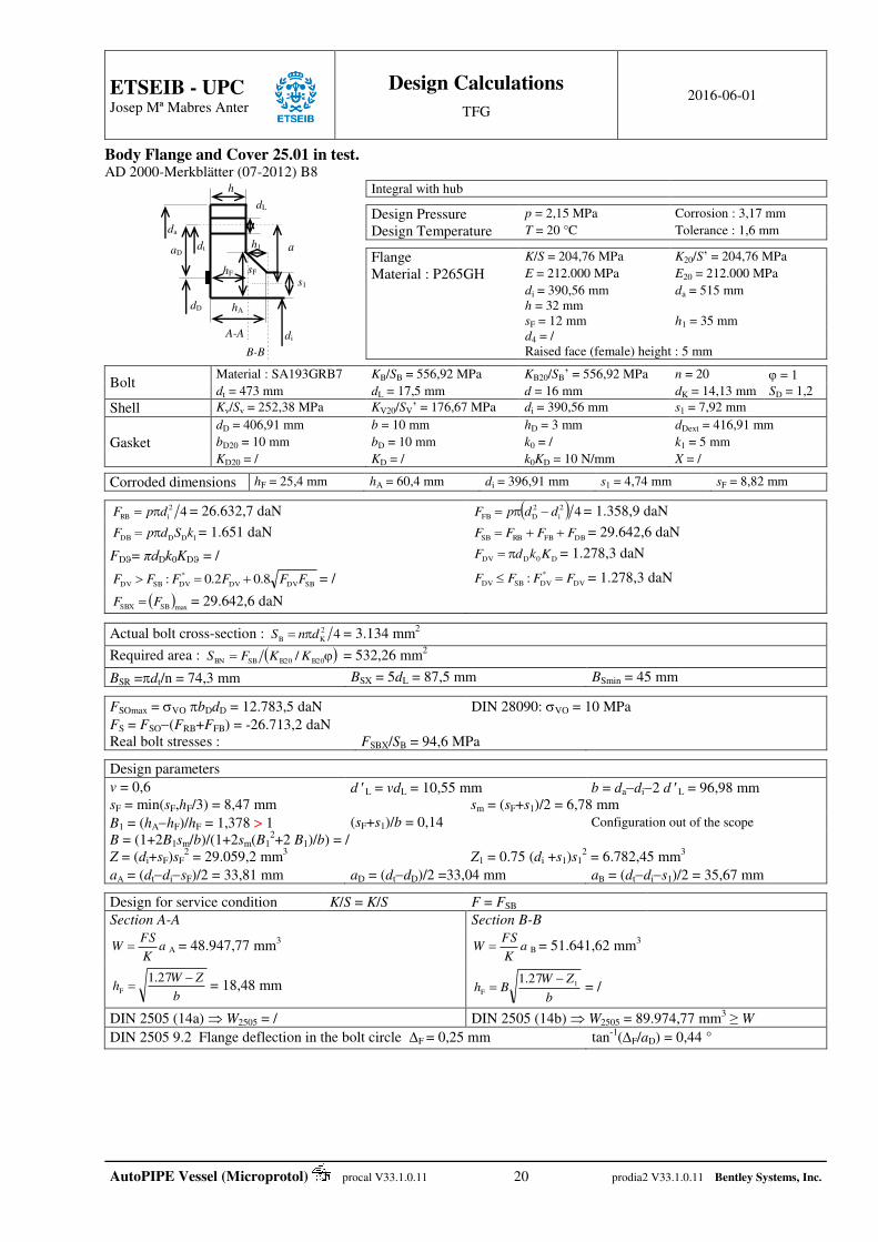
Body Flange and Cover 25.01 in test. AD 2000-Merkblätter (07-2012) B8
Integral with hub
Design Pressure p = 2,15 MPa Corrosion : 3,17 mm
Design Temperature T = 20 °C Tolerance : 1,6 mm
Flange K/S = 204,76 MPa K20/S’ = 204,76 MPa
Material : P265GH E = 212.000 MPa E20 = 212.000 MPa
di = 390,56 mm da = 515 mm h = 32 mm sF = 12 mm h1 = 35 mm d4 = / Raised face (female) height : 5 mm
Bolt Material : SA193GRB7 KB/SB = 556,92 MPa KB20/SB’ = 556,92 MPa n = 20 = 1
dt = 473 mm dL = 17,5 mm d = 16 mm dK = 14,13 mm SD = 1,2
Shell Kv/Sv = 252,38 MPa KV20/SV’ = 176,67 MPa di = 390,56 mm s1 = 7,92 mm
dD = 406,91 mm b = 10 mm hD = 3 mm dDext = 416,91 mm
Gasket bD20 = 10 mm bD = 10 mm k0 = / k1 = 5 mm
KD20 = / KD = / k0KD = 10 N/mm X = / Corroded dimensions hF = 25,4 mm hA = 60,4 mm di = 396,91 mm s1 = 4,74 mm sF = 8,82 mm
42
iRB dpF = 26.632,7 daN 42
i
2
DFB ddpF = 1.358,9 daN
1DDDB kSdpF = 1.651 daN DBFBRBSB FFFF = 29.642,6 daN
FD= πdDk0KD = / D0DDV KkdF = 1.278,3 daN
SBDVDV
*
DVSBDV 8.02.0: FFFFFF = / DV
*
DVSBDV : FFFF = 1.278,3 daN
maxSBSBX FF = 29.642,6 daN
Actual bolt cross-section : 42
KB dnS = 3.134 mm2
Required area : B20B20SBBN / KKFS = 532,26 mm2
BSR =dt/n = 74,3 mm BSX = 5dL = 87,5 mm BSmin = 45 mm FSOmax = VO bDdD = 12.783,5 daN DIN 28090: VO = 10 MPa
FS = FSO(FRB+FFB) = -26.713,2 daN
Real bolt stresses : FSBX/SB = 94,6 MPa Design parameters
v = 0,6 d L = vdL = 10,55 mm b = dadi2 d L = 96,98 mm sF = min(sF,hF/3) = 8,47 mm sm = (sF+s1)/2 = 6,78 mm
B1 = (hAhF)/hF = 1,378 > 1 (sF+s1)/b = 0,14 Configuration out of the scope
B = (1+2B1sm/b)/(1+2sm(B12+2 B1)/b) = /
Z = (di+sF)sF2 = 29.059,2 mm3 Z1 = 0.75 (di +s1)s1
2 = 6.782,45 mm3
aA = (dtdisF)/2 = 33,81 mm aD = (dtdD)/2 =33,04 mm aB = (dtdis1)/2 = 35,67 mm Design for service condition K/S = K/S F = FSB
Section A-A Section B-B
aK
FSW A = 48.947,77 mm3 a
K
FSW B = 51.641,62 mm3
b
ZWh
27.1F = 18,48 mm
b
ZWBh 1
F
27.1 = /
DIN 2505 (14a) W2505 = / DIN 2505 (14b) W2505 = 89.974,77 mm3 ≥ W
DIN 2505 9.2 Flange deflection in the bolt circle F = 0,25 mm tan-1(F/aD) = 0,44 °
s1
da
dt
dD
sF
hA
h
di
dL
aD a
A-A
B-B
hF
h1
ETSEIB - UPC
Josep Mª Mabres Anter
Design Calculations
TFG 2016-06-01
AutoPIPE Vessel (Microprotol) procal V33.1.0.11 21 prodia2 V33.1.0.11 Bentley Systems, Inc.
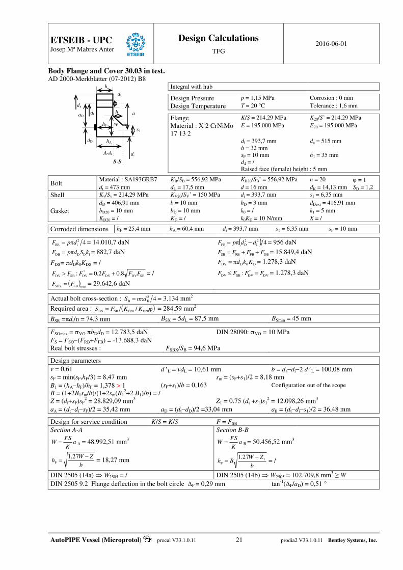
Body Flange and Cover 30.03 in test. AD 2000-Merkblätter (07-2012) B8
Integral with hub
Design Pressure p = 1,15 MPa Corrosion : 0 mm
Design Temperature T = 20 °C Tolerance : 1,6 mm
Flange K/S = 214,29 MPa K20/S’ = 214,29 MPa
Material : X 2 CrNiMo 17 13 2
E = 195.000 MPa E20 = 195.000 MPa
di = 393,7 mm da = 515 mm h = 32 mm sF = 10 mm h1 = 35 mm d4 = / Raised face (female) height : 5 mm
Bolt Material : SA193GRB7 KB/SB = 556,92 MPa KB20/SB’ = 556,92 MPa n = 20 = 1
dt = 473 mm dL = 17,5 mm d = 16 mm dK = 14,13 mm SD = 1,2
Shell Kv/Sv = 214,29 MPa KV20/SV’ = 150 MPa di = 393,7 mm s1 = 6,35 mm
dD = 406,91 mm b = 10 mm hD = 3 mm dDext = 416,91 mm
Gasket bD20 = 10 mm bD = 10 mm k0 = / k1 = 5 mm
KD20 = / KD = / k0KD = 10 N/mm X = / Corroded dimensions hF = 25,4 mm hA = 60,4 mm di = 393,7 mm s1 = 6,35 mm sF = 10 mm
42
iRB dpF = 14.010,7 daN 42
i
2
DFB ddpF = 956 daN
1DDDB kSdpF = 882,7 daN DBFBRBSB FFFF = 15.849,4 daN
FD= πdDk0KD = / D0DDV KkdF = 1.278,3 daN
SBDVDV
*
DVSBDV 8.02.0: FFFFFF = / DV
*
DVSBDV : FFFF = 1.278,3 daN
maxSBSBX FF = 29.642,6 daN
Actual bolt cross-section : 42
KB dnS = 3.134 mm2
Required area : B20B20SBBN / KKFS = 284,59 mm2
BSR =dt/n = 74,3 mm BSX = 5dL = 87,5 mm BSmin = 45 mm FSOmax = VO bDdD = 12.783,5 daN DIN 28090: VO = 10 MPa
FS = FSO(FRB+FFB) = -13.688,3 daN
Real bolt stresses : FSBX/SB = 94,6 MPa Design parameters
v = 0,61 d L = vdL = 10,61 mm b = dadi2 d L = 100,08 mm sF = min(sF,hF/3) = 8,47 mm sm = (sF+s1)/2 = 8,18 mm
B1 = (hAhF)/hF = 1,378 > 1 (sF+s1)/b = 0,163 Configuration out of the scope
B = (1+2B1sm/b)/(1+2sm(B12+2 B1)/b) = /
Z = (di+sF)sF2 = 28.829,09 mm3 Z1 = 0.75 (di +s1)s1
2 = 12.098,26 mm3
aA = (dtdisF)/2 = 35,42 mm aD = (dtdD)/2 =33,04 mm aB = (dtdis1)/2 = 36,48 mm Design for service condition K/S = K/S F = FSB
Section A-A Section B-B
aK
FSW A = 48.992,51 mm3 a
K
FSW B = 50.456,52 mm3
b
ZWh
27.1F = 18,27 mm
b
ZWBh 1
F
27.1 = /
DIN 2505 (14a) W2505 = / DIN 2505 (14b) W2505 = 102.709,8 mm3 ≥ W
DIN 2505 9.2 Flange deflection in the bolt circle F = 0,29 mm tan-1(F/aD) = 0,51 °
s1
da
dt
dD
sF
hA
h
di
dL
aD a
A-A
B-B
hF
h1

ETSEIB - UPC
Josep Mª Mabres Anter
Design Calculations
TFG 2016-06-01
AutoPIPE Vessel (Microprotol) procal V33.1.0.11 22 prodia2 V33.1.0.11 Bentley Systems, Inc.
Body Flange and Cover 3903 in test. AD 2000-Merkblätter (07-2012) B8
Backing Flange
Design Pressure p = 2,15 MPa Corrosion : 0 mm
Design Temperature T = 20 °C Tolerance : 1,6 mm
Flange K/S = 233,33 MPa K20/S’ = 233,33 MPa
Material : P265GH E = 212.000 MPa E20 = 212.000 MPa
di = 393,7 mm da = 515 mm h = 32 mm sF = / h1 = / d4 = 416,91 mm Flat face
Bolt Material : SA193GRB7 KB/SB = 556,92 MPa KB20/SB’ = 556,92 MPa n = 20 = 1
dt = 473 mm dL = 17,5 mm d = 16 mm dK = 14,13 mm SD = 1,2
Shell Kv/Sv = 214,29 MPa KV20/SV’ = 150 MPa di = 0 mm s1 = 0 mm
dD = 406,91 mm b = 10 mm hD = 3 mm dDext = 416,91 mm
Gasket bD20 = 10 mm bD = 10 mm k0 = / k1 = 5 mm
KD20 = / KD = / k0KD = 10 N/mm X = / Corroded dimensions hF = 30,4 mm hA = / d = / s1 = / sF = /
42
iRB dpF = 26.203,6 daN 42
i
2
DFB ddpF = 1.787,9 daN
1DDDB kSdpF = 1.651 daN DBFBRBSB FFFF = 29.642,6 daN
FD= πdDk0KD = / D0DDV KkdF = 1.278,3 daN
SBDVDV
*
DVSBDV 8.02.0: FFFFFF = / DV
*
DVSBDV : FFFF = 1.278,3 daN
maxSBSBX FF = 29.642,6 daN
max
*
DVDVX FF = 1.278,3 daN Bolting
Actual bolt cross-section : 42
KB dnS = 3.134 mm2 SZ 4
Required area : BBSBBN / SKFS = 532,26 mm2 nSD π4 BNreq = 5,82 mm
c5 = 3 mm (Z(FSB/(Kn))0.5 ≤ 20)
42
5reqBN cDnS = 532,26 mm2 B20B20DVBNE / SKFS = 22,95 mm2
BSR =dt/n = 74,3 mm BSX = 5dL = 87,5 mm BSmin = 45 mm
FSO = User Defined = 1.278,3 daN > FDV
FSOmax = VO bDdD = 12.783,5 daN DIN 28090: VO = 10 MPa
Fsmax = BObDdD = 12.783,5 daN DIN 28090: BO = 10 MPa
FS = FSO(FRB+FFB) = -26.713,2 daN Bolt Load : FSO/n = 63,9 daN
Real bolt stresses : FSBX/SB = 94,6 MPa FSO/SB = 4,1 MPa Design parameters
v = 0,61 d L = vdL = 10,61 mm b = dadi2 d L = 100,08 mm
a = (dtd4)/2 = 28,04 mm a = (dtdis1)/2 = / aD = (dtd4)/2 = 28,04 mm Design for bolting-up condition K/S = K20/S' F = FDV
aK
FSW D = 1.536,48 mm3
b
Wh
27.1F = 4,42 mm
Design for service condition K/S = K/S F = FSB
aK
FSW = 35.628,29 mm3
b
Wh
27.1F = 21,26 mm
2
i
2
4
SBF 27.1
dd
Fp
= 20,01 MPa ≤ 225 MPa
hF
a
di
dt
da
dL

ETSEIB - UPC
Josep Mª Mabres Anter
Design Calculations
TFG 2016-06-01
AutoPIPE Vessel (Microprotol) procal V33.1.0.11 23 prodia2 V33.1.0.11 Bentley Systems, Inc.
Tubesheet(s) and Expansion Joint Tubesheet, Loading conditions 1 [corroded normal condition] AD 2000-Merkblatt B 5, 07.2012.
AD B5 ch 6.7.2 Plate
Tubes Tubeside Shellside Tubeside Shellside
Pressure pi= 1,2 MPa pu= 0,8 MPa Corrosion c2i = 3,17 mm c2u = 0 mm Material X 2 CrNiMo 17 13 2 X2CrNiMo17-12-2
Design Temperature 260 °C 260 °C / /
Nominal stress K/S = 103,1 MPa
K20/S20 = / Kt/St = 100,9 MPa / /
Modulus of elasticity E =178.200 MPa Et = 179.200 MPa / / Nominal thicknesses sa = 43 mm st = 2,11 mm 3,76 mm 5,56 mm
Diameter Da = 416,91 mm da=25,4 mm di=21,18 m
m DIt = 398,89 mm DIc = 395,29 mm
Tolerance c1 = 1,6 mm
Pattern Rotated Triangular n = 56 Aro = / t = 31,75 mm Al = / Tubeside Shellside
Design Diameter : D1t = 406,91 mm D1c = 406,91 mm Partition groove depth : 0 mm 5 mm
d t = 473 mm dDc = 406,91 mm Peripheral extra thicknesses : 10 mm Central extra thicknesses xx: 5 mm
Design parameters
Exp. Length : l*w
2.1;2max a
*
wttta
*
a
d
s
l
K
K
E
Esdd
Ligament efficiencyt
dtv
*
a Tube cross-section :
4
2
i
2
at
ddA
l
*w d
*a v At
stationary Tubesheet 12 mm 24,25 mm 0,23629 154,25 mm2
Calculation of tube loads
Tensile load / inner tube : 4
i
2
iti
πpdF Compressive load / inner tube :
4
π i
2
ici
Maximum load / tube FR = max (Fti , Fci)
Fti Fci FR
423 N 0 N 423 N
Calculation of admissible loads per tube
In tensile/compressive case : tttTX SKAF = 15.569 N FR ≤ FTX
Tube-to-Tubesheet Joint
Minimum expanded length :
-Even lw1 = FR / [150 min(dadi , 0.1da)]
-With groove lw2 = FR / [300 min(dadi , 0.1da)] -With flange lw3 = FR / [400 min(dadi , 0.1da)] Welded tubes : -Minimum thickness of welded joints g = 0.4(FRS)/(daK)
lw1 lw2 lw3 g
1,11 mm 0,56 mm 0,42 mm /
Connection-manufacturing must respect code rules (AD B5 6.7.1.2 : lw mini = 12 mm)
sa
DIt dDt
dDc
sR
DIc
dt

ETSEIB - UPC
Josep Mª Mabres Anter
Design Calculations
TFG 2016-06-01
AutoPIPE Vessel (Microprotol) procal V33.1.0.11 24 prodia2 V33.1.0.11 Bentley Systems, Inc.
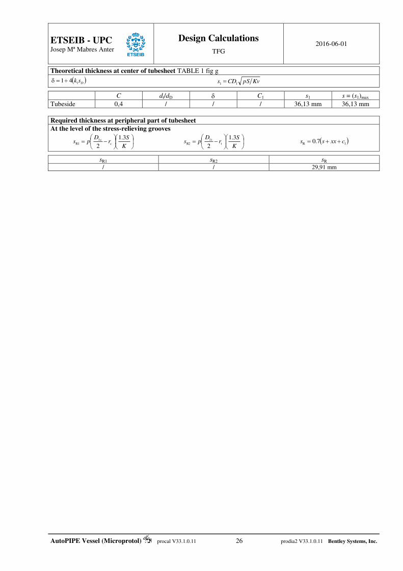
Theoretical thickness at center of tubesheet TABLE 1 fig g
D
sk141 KvpSCDs 11
C dt/dD C1 s1 s = (s1)max
Shellside Tubeside
0,4 0,4
/ /
/ /
/ /
29,5 mm 36,13 mm
36,13 mm
Required thickness at peripheral part of tubesheet
At the level of the stress-relieving grooves
K
Sr
Dps
3.1
2c
1cR1
K
Sr
Dps
3.1
2t
1tR2 1R 7.0 cxxss
sR1 sR2 sR / / 29,91 mm

ETSEIB - UPC
Josep Mª Mabres Anter
Design Calculations
TFG 2016-06-01
AutoPIPE Vessel (Microprotol) procal V33.1.0.11 25 prodia2 V33.1.0.11 Bentley Systems, Inc.
Tubesheet, Loading conditions 2 [corroded normal condition] AD 2000-Merkblatt B 5, 07.2012.
AD B5 ch 6.7.2 Plate
Tubes Tubeside Shellside Tubeside Shellside
Pressure pi= 1,2 MPa pu= 0 MPa Corrosion c2i = 3,17 mm c2u = 0 mm Material X 2 CrNiMo 17 13 2 X2CrNiMo17-12-2
Design Temperature 260 °C 260 °C / /
Nominal stress K/S = 103,1 MPa
K20/S20 = / Kt/St = 100,9 MPa / /
Modulus of elasticity E =178.200 MPa Et = 179.200 MPa / / Nominal thicknesses sa = 43 mm st = 2,11 mm 3,76 mm 5,56 mm
Diameter Da = 416,91 mm da=25,4 mm di=21,18 m
m DIt = 398,89 mm DIc = 395,29 mm
Tolerance c1 = 1,6 mm
Pattern Rotated Triangular n = 56 Aro = / t = 31,75 mm Al = / Tubeside Shellside
Design Diameter : D1t = 406,91 mm D1c = 406,91 mm Partition groove depth : 0 mm 5 mm
d t = 473 mm dDc = 406,91 mm Peripheral extra thicknesses : 10 mm Central extra thicknesses xx: 5 mm
Design parameters
Exp. Length : l*w
2.1;2max a
*
wttta
*
a
d
s
l
K
K
E
Esdd
Ligament efficiencyt
dtv
*
a Tube cross-section :
4
2
i
2
at
ddA
l
*w d
*a v At
stationary Tubesheet 12 mm 24,25 mm 0,23629 154,25 mm2
Calculation of tube loads
Tensile load / inner tube : 4
i
2
iti
πpdF Compressive load / inner tube :
4
π i
2
ici
Maximum load / tube FR = max (Fti , Fci)
Fti Fci FR
423 N 0 N 423 N
Calculation of admissible loads per tube
In tensile/compressive case : tttTX SKAF = 15.569 N FR ≤ FTX
Tube-to-Tubesheet Joint
Minimum expanded length :
-Even lw1 = FR / [150 min(dadi , 0.1da)]
-With groove lw2 = FR / [300 min(dadi , 0.1da)] -With flange lw3 = FR / [400 min(dadi , 0.1da)] Welded tubes : -Minimum thickness of welded joints g = 0.4(FRS)/(daK)
lw1 lw2 lw3 g
1,11 mm 0,56 mm 0,42 mm /
Connection-manufacturing must respect code rules (AD B5 6.7.1.2 : lw mini = 12 mm)
sa
DIt dDt
dDc
sR
DIc
dt
ETSEIB - UPC
Josep Mª Mabres Anter
Design Calculations
TFG 2016-06-01
AutoPIPE Vessel (Microprotol) procal V33.1.0.11 26 prodia2 V33.1.0.11 Bentley Systems, Inc.
Theoretical thickness at center of tubesheet TABLE 1 fig g
D
sk141 KvpSCDs 11
C dt/dD C1 s1 s = (s1)max
Tubeside 0,4 / / / 36,13 mm 36,13 mm
Required thickness at peripheral part of tubesheet
At the level of the stress-relieving grooves
K
Sr
Dps
3.1
2c
1cR1
K
Sr
Dps
3.1
2t
1tR2 1R 7.0 cxxss
sR1 sR2 sR / / 29,91 mm

ETSEIB - UPC
Josep Mª Mabres Anter
Design Calculations
TFG 2016-06-01
AutoPIPE Vessel (Microprotol) procal V33.1.0.11 27 prodia2 V33.1.0.11 Bentley Systems, Inc.
Tubesheet, Loading conditions 3 [corroded normal condition] AD 2000-Merkblatt B 5, 07.2012.
AD B5 ch 6.7.2 Plate
Tubes Tubeside Shellside Tubeside Shellside
Pressure pi= 0 MPa pu= 0,8 MPa Corrosion c2i = 3,17 mm c2u = 0 mm Material X 2 CrNiMo 17 13 2 X2CrNiMo17-12-2
Design Temperature 260 °C 260 °C / /
Nominal stress K/S = 103,1 MPa
K20/S20 = / Kt/St = 100,9 MPa / /
Modulus of elasticity E =178.200 MPa Et = 179.200 MPa / / Nominal thicknesses sa = 43 mm st = 2,11 mm 3,76 mm 5,56 mm
Diameter Da = 416,91 mm da=25,4 mm di=21,18 m
m DIt = 398,89 mm DIc = 395,29 mm
Tolerance c1 = 1,6 mm
Pattern Rotated Triangular n = 56 Aro = / t = 31,75 mm Al = / Tubeside Shellside
Design Diameter : D1t = 406,91 mm D1c = 406,91 mm Partition groove depth : 0 mm 5 mm
d t = 473 mm dDc = 406,91 mm Peripheral extra thicknesses : 10 mm Central extra thicknesses xx: 5 mm
Design parameters
Exp. Length : l*w
2.1;2max a
*
wttta
*
a
d
s
l
K
K
E
Esdd
Ligament efficiencyt
dtv
*
a Tube cross-section :
4
2
i
2
at
ddA
l
*w d
*a v At
stationary Tubesheet 12 mm 24,25 mm 0,23629 154,25 mm2
Calculation of tube loads
Tensile load / inner tube : 4
i
2
iti
πpdF Compressive load / inner tube :
4
π i
2
ici
Maximum load / tube FR = max (Fti , Fci)
Fti Fci FR
0 N 0 N 0 N
Calculation of admissible loads per tube
In tensile/compressive case : tttTX SKAF = 15.569 N FR ≤ FTX
Tube-to-Tubesheet Joint
Minimum expanded length :
-Even lw1 = FR / [150 min(dadi , 0.1da)]
-With groove lw2 = FR / [300 min(dadi , 0.1da)] -With flange lw3 = FR / [400 min(dadi , 0.1da)] Welded tubes : -Minimum thickness of welded joints g = 0.4(FRS)/(daK)
lw1 lw2 lw3 g
0 mm 0 mm 0 mm /
Connection-manufacturing must respect code rules (AD B5 6.7.1.2 : lw mini = 12 mm)
sa
DIt dDt
dDc
sR
DIc
dt

ETSEIB - UPC
Josep Mª Mabres Anter
Design Calculations
TFG 2016-06-01
AutoPIPE Vessel (Microprotol) procal V33.1.0.11 28 prodia2 V33.1.0.11 Bentley Systems, Inc.
Theoretical thickness at center of tubesheet TABLE 1 fig g
D
sk141 KvpSCDs 11
C dt/dD C1 s1 s = (s1)max
Shellside 0,4 / / / 29,5 mm 29,5 mm
Required thickness at peripheral part of tubesheet
At the level of the stress-relieving grooves
K
Sr
Dps
3.1
2c
1cR1
K
Sr
Dps
3.1
2t
1tR2 1R 7.0 cxxss
sR1 sR2 sR / / 25,27 mm
ETSEIB - UPC
Josep Mª Mabres Anter
Design Calculations
TFG 2016-06-01
AutoPIPE Vessel (Microprotol) procal V33.1.0.11 29 prodia2 V33.1.0.11 Bentley Systems, Inc.
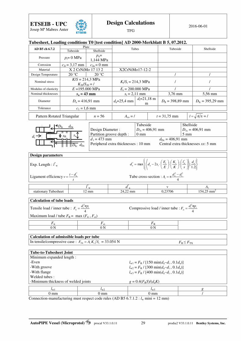
Tubesheet, Loading conditions T0 [test condition] AD 2000-Merkblatt B 5, 07.2012.
AD B5 ch 6.7.2 Plate
Tubes Tubeside Shellside Tubeside Shellside
Pressure pi= 0 MPa pu=
1,144 MPa
Corrosion c2i = 3,17 mm c2u = 0 mm Material X 2 CrNiMo 17 13 2 X2CrNiMo17-12-2
Design Temperature 20 °C 20 °C / /
Nominal stress K/S = 214,3 MPa
K20/S20 = / Kt/St = 214,3 MPa / /
Modulus of elasticity E =195.000 MPa Et = 200.000 MPa / / Nominal thicknesses sa = 43 mm st = 2,11 mm 3,76 mm 5,56 mm
Diameter Da = 416,91 mm da=25,4 mm di=21,18 m
m DIt = 398,89 mm DIc = 395,29 mm
Tolerance c1 = 1,6 mm
Pattern Rotated Triangular n = 56 Aro = / t = 31,75 mm Al = / Tubeside Shellside
Design Diameter : D1t = 406,91 mm D1c = 406,91 mm Partition groove depth : 0 mm 5 mm
d t = 473 mm dDc = 406,91 mm Peripheral extra thicknesses : 10 mm Central extra thicknesses xx: 5 mm
Design parameters
Exp. Length : l*w
2.1;2max a
*
wttta
*
a
d
s
l
K
K
E
Esdd
Ligament efficiencyt
dtv
*
a Tube cross-section :
4
2
i
2
at
ddA
l
*w d
*a v At
stationary Tubesheet 12 mm 24,22 mm 0,23706 154,25 mm2
Calculation of tube loads
Tensile load / inner tube : 4
i
2
iti
πpdF Compressive load / inner tube :
4
π i
2
ici
Maximum load / tube FR = max (Fti , Fci)
Fti Fci FR
0 N 0 N 0 N
Calculation of admissible loads per tube
In tensile/compressive case : tttTX SKAF = 33.054 N FR ≤ FTX
Tube-to-Tubesheet Joint
Minimum expanded length :
-Even lw1 = FR / [150 min(dadi , 0.1da)] -With groove lw2 = FR / [300 min(dadi , 0.1da)]
-With flange lw3 = FR / [400 min(dadi , 0.1da)] Welded tubes : -Minimum thickness of welded joints g = 0.4(FRS)/(daK)
lw1 lw2 lw3 g
0 mm 0 mm 0 mm /
Connection-manufacturing must respect code rules (AD B5 6.7.1.2 : lw mini = 12 mm)
sa
DIt dDt
dDc
sR
DIc
dt

ETSEIB - UPC
Josep Mª Mabres Anter
Design Calculations
TFG 2016-06-01
AutoPIPE Vessel (Microprotol) procal V33.1.0.11 30 prodia2 V33.1.0.11 Bentley Systems, Inc.
Theoretical thickness at center of tubesheet TABLE 1 fig g
D
sk141 KvpSCDs 11
C dt/dD C1 s1 s = (s1)max
Shellside 0,4 / / / 24,43 mm 24,43 mm
Required thickness at peripheral part of tubesheet
At the level of the stress-relieving grooves
K
Sr
Dps
3.1
2c
1cR1
K
Sr
Dps
3.1
2t
1tR2 1R 7.0 cxxss
sR1 sR2 sR / / 21,72 mm

ETSEIB - UPC
Josep Mª Mabres Anter
Design Calculations
TFG 2016-06-01
AutoPIPE Vessel (Microprotol) procal V33.1.0.11 31 prodia2 V33.1.0.11 Bentley Systems, Inc.
Tubesheet, Loading conditions 0T [test condition] AD 2000-Merkblatt B 5, 07.2012.
AD B5 ch 6.7.2 Plate
Tubes Tubeside Shellside Tubeside Shellside
Pressure pi=
2,149 MPa pu= 0 MPa
Corrosion c2i = 3,17 mm c2u = 0 mm Material X 2 CrNiMo 17 13 2 X2CrNiMo17-12-2
Design Temperature 20 °C 20 °C / /
Nominal stress K/S = 214,3 MPa
K20/S20 = / Kt/St = 214,3 MPa / /
Modulus of elasticity E =195.000 MPa Et = 200.000 MPa / / Nominal thicknesses sa = 43 mm st = 2,11 mm 3,76 mm 5,56 mm
Diameter Da = 416,91 mm da=25,4 mm di=21,18 m
m DIt = 398,89 mm DIc = 395,29 mm
Tolerance c1 = 1,6 mm
Pattern Rotated Triangular n = 56 Aro = / t = 31,75 mm Al = / Tubeside Shellside
Design Diameter : D1t = 406,91 mm D1c = 406,91 mm Partition groove depth : 0 mm 5 mm
d t = 473 mm dDc = 406,91 mm Peripheral extra thicknesses : 10 mm Central extra thicknesses xx: 5 mm
Design parameters
Exp. Length : l*w
2.1;2max a
*
wttta
*
a
d
s
l
K
K
E
Esdd
Ligament efficiencyt
dtv
*
a Tube cross-section :
4
2
i
2
at
ddA
l
*w d
*a v At
stationary Tubesheet 12 mm 24,22 mm 0,23706 154,25 mm2
Calculation of tube loads
Tensile load / inner tube : 4
i
2
iti
πpdF Compressive load / inner tube :
4
π i
2
ici
Maximum load / tube FR = max (Fti , Fci)
Fti Fci FR
757 N 0 N 757 N
Calculation of admissible loads per tube
In tensile/compressive case : tttTX SKAF = 33.054 N FR ≤ FTX
Tube-to-Tubesheet Joint
Minimum expanded length :
-Even lw1 = FR / [150 min(dadi , 0.1da)] -With groove lw2 = FR / [300 min(dadi , 0.1da)]
-With flange lw3 = FR / [400 min(dadi , 0.1da)] Welded tubes : -Minimum thickness of welded joints g = 0.4(FRS)/(daK)
lw1 lw2 lw3 g
1,99 mm 0,99 mm 0,75 mm /
Connection-manufacturing must respect code rules (AD B5 6.7.1.2 : lw mini = 12 mm)
sa
DIt dDt
dDc
sR
DIc
dt

ETSEIB - UPC
Josep Mª Mabres Anter
Design Calculations
TFG 2016-06-01
AutoPIPE Vessel (Microprotol) procal V33.1.0.11 32 prodia2 V33.1.0.11 Bentley Systems, Inc.
Theoretical thickness at center of tubesheet TABLE 1 fig g
D
sk141 KvpSCDs 11
C dt/dD C1 s1 s = (s1)max
Tubeside 0,4 / / / 33,47 mm 33,47 mm
Required thickness at peripheral part of tubesheet
At the level of the stress-relieving grooves
K
Sr
Dps
3.1
2c
1cR1
K
Sr
Dps
3.1
2t
1tR2 1R 7.0 cxxss
sR1 sR2 sR / / 28,05 mm
ETSEIB - UPC
Josep Mª Mabres Anter
Design Calculations
TFG 2016-06-01
AutoPIPE Vessel (Microprotol) procal V33.1.0.11 33 prodia2 V33.1.0.11 Bentley Systems, Inc.
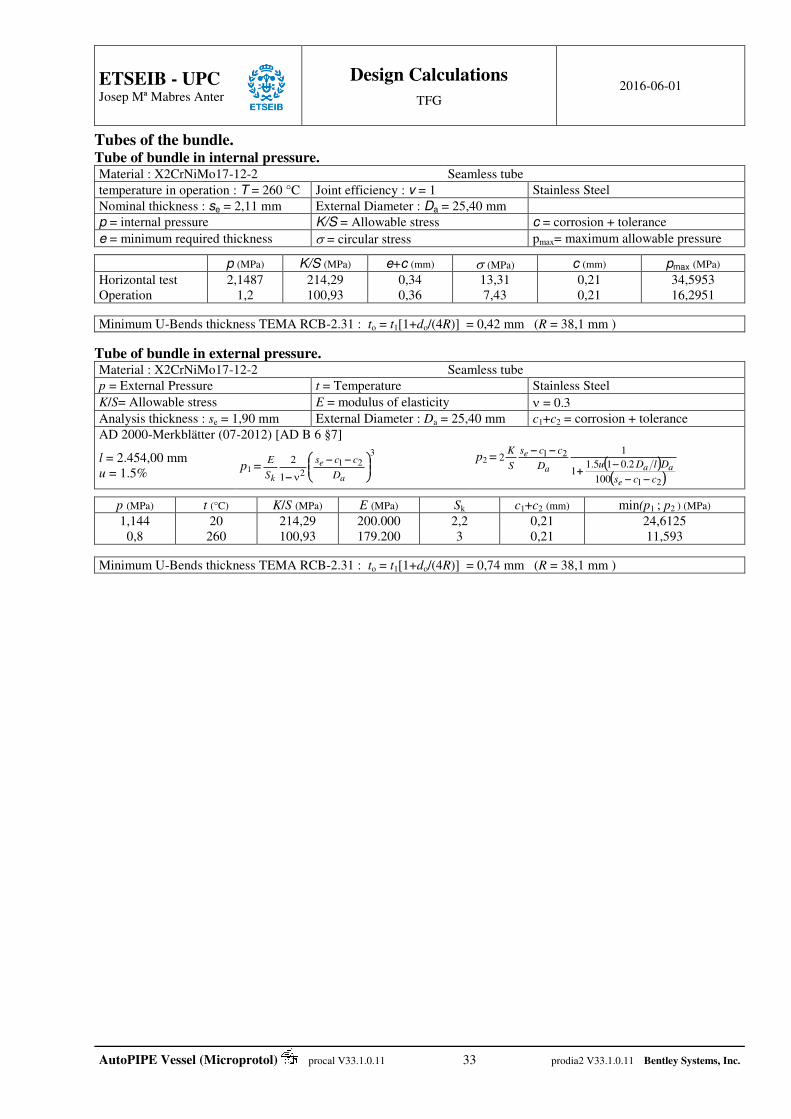
Tubes of the bundle. Tube of bundle in internal pressure. Material : X2CrNiMo17-12-2 Seamless tube
temperature in operation : T = 260 °C Joint efficiency : v = 1 Stainless Steel
Nominal thickness : se = 2,11 mm External Diameter : Da = 25,40 mm
p = internal pressure K/S = Allowable stress c = corrosion + tolerance
e = minimum required thickness = circular stress pmax= maximum allowable pressure
p (MPa) K/S (MPa) e+c (mm) (MPa) c (mm) pmax (MPa)
Horizontal test Operation
2,1487 1,2
214,29 100,93
0,34 0,36
13,31 7,43
0,21 0,21
34,5953 16,2951
Minimum U-Bends thickness TEMA RCB-2.31 : to = t1[1+do/(4R)] = 0,42 mm (R = 38,1 mm )
Tube of bundle in external pressure. Material : X2CrNiMo17-12-2 Seamless tube
p = External Pressure t = Temperature Stainless Steel
K/S= Allowable stress E = modulus of elasticity = 0.3
Analysis thickness : se = 1,90 mm External Diameter : Da = 25,40 mm c1+c2 = corrosion + tolerance
AD 2000-Merkblätter (07-2012) [AD B 6 §7]
l = 2.454,00 mm
u = 1.5% p1 =
321
21
2
a
e
k D
ccs
S
E
p2 = 21
21
100
2.015.11
12
ccs
DlDuD
ccs
S
K
e
aaa
e
p (MPa) t (°C) K/S (MPa) E (MPa) Sk c1+c2 (mm) min(p1 ; p2 ) (MPa)
1,144 0,8
20 260
214,29 100,93
200.000 179.200
2,2 3
0,21 0,21
24,6125 11,593
Minimum U-Bends thickness TEMA RCB-2.31 : to = t1[1+do/(4R)] = 0,74 mm (R = 38,1 mm )
ETSEIB - UPC
Josep Mª Mabres Anter
Design Calculations
TFG 2016-06-01
AutoPIPE Vessel (Microprotol) procal V33.1.0.11 34 prodia2 V33.1.0.11 Bentley Systems, Inc.
Vessel under combination loading Model for stress analysis due to supporting.
Reaction per support, bending moment and shear loads is done from a beam model simply supported, one of the support is fix at left or right of the beam.
The beam study use the reduction matrix method found on the Falk transmission matrix.
Boundary conditions allow solving slope and moment not affected when crossing the support.
External single load and moment are applied at their acting point and are considered as a discontinuity as an inertia or modulus of elasticity change. Distributed loads do not constitute a discontinuity.
Reference axis are : beam x on the right, y up with positive loads down, moments > 0 from x to y.
Shell own weight, liquid, and bundle are considered as distributed loads while head weight, flange and cover, floating head and nozzle are considered as concentrated loads.
Termination heads are removed and replaced as a concentrated load and an external moment. The resultant of the hydrostatic pressure applied to its location also result in an external moment.
For each study case, analysis is done for the vertical and/or horizontal plan. Saddle reactions and bending moment used for shell stresses check are the vector sum of the two plans. This also provides the new angle where the shell stress check must be done
Thermal effects are due to the friction factor at the bottom of the saddle and results in an additional moment at the
saddle location. Fixed saddle resists to all others. ( = 0,3)
Principal stresses are f1 = 0.5[ ]σθ + σz + (σθ – σz)2 + 4 2 and f2 = 0.5[ ]σθ + σz – (σθ – σz)
2 + 4 2 and general
primary membrane stress intensity is σeq = max( )| |f1–f2 ;| |f1+0.5p ;| |f2+0.5p , with σθ : circumferential stress , σz :
longitudinal stress and : shear stress.
Stresses in saddle are studied in the 3 axes.
For wind and earthquake design purpose, vibration period are evaluated from the general modal equation [k-ω².m] Φ = 0 and solving the eigenvectors and eigenvalues.
The flexibility matrix 1/k is found from the beam analysis method, using unit loads applied one after one at the masse location.
The dynamic matrix is found to be 1/g.1/k.m with g = acceleration due to gravity and m = mass matrix.
Eigenvectors correspond to the natural modes and eigenvalues to their frequencies.
Subtracting the contribution of the studied mode from the starting vector allows converging to higher modes
Dunkerley method is used for stacked vessels. This enables to find the global circular frequency to 1/ω2 = 2/ω12 where
ω1 is the circular frequency of one vessel. Finally the vibration period is T = 2π/ω
ETSEIB - UPC
Josep Mª Mabres Anter
Design Calculations
TFG 2016-06-01
AutoPIPE Vessel (Microprotol) procal V33.1.0.11 35 prodia2 V33.1.0.11 Bentley Systems, Inc.
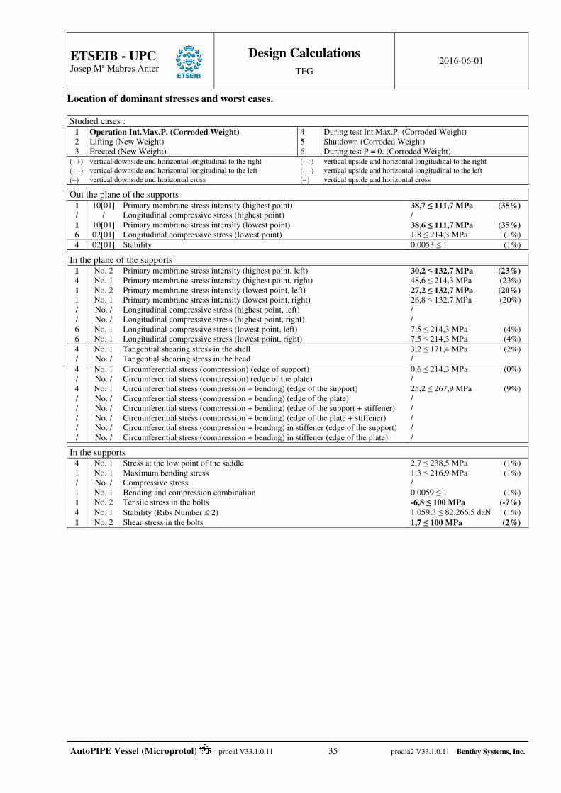
Location of dominant stresses and worst cases.
Studied cases : 1 2 3
Operation Int.Max.P. (Corroded Weight) Lifting (New Weight) Erected (New Weight)
4 5 6
During test Int.Max.P. (Corroded Weight) Shutdown (Corroded Weight) During test P = 0. (Corroded Weight)
() vertical downside and horizontal longitudinal to the right () vertical upside and horizontal longitudinal to the right
() vertical downside and horizontal longitudinal to the left () vertical upside and horizontal longitudinal to the left
() vertical downside and horizontal cross () vertical upside and horizontal cross Out the plane of the supports
1 10[01] Primary membrane stress intensity (highest point) 38,7 ≤ 111,7 MPa (35%) / / Longitudinal compressive stress (highest point) /
1 10[01] Primary membrane stress intensity (lowest point) 38,6 ≤ 111,7 MPa (35%) 6 02[01] Longitudinal compressive stress (lowest point) 1,8 ≤ 214,3 MPa (1%)
4 02[01] Stability 0,0053 ≤ 1 (1%) In the plane of the supports
1 No. 2 Primary membrane stress intensity (highest point, left) 30,2 ≤ 132,7 MPa (23%) 4 No. 1 Primary membrane stress intensity (highest point, right) 48,6 ≤ 214,3 MPa (23%) 1 No. 2 Primary membrane stress intensity (lowest point, left) 27,2 ≤ 132,7 MPa (20%) 1 No. 1 Primary membrane stress intensity (lowest point, right) 26,8 ≤ 132,7 MPa (20%) / No. / Longitudinal compressive stress (highest point, left) / / No. / Longitudinal compressive stress (highest point, right) / 6 No. 1 Longitudinal compressive stress (lowest point, left) 7,5 ≤ 214,3 MPa (4%) 6 No. 1 Longitudinal compressive stress (lowest point, right) 7,5 ≤ 214,3 MPa (4%)
4 No. 1 Tangential shearing stress in the shell 3,2 ≤ 171,4 MPa (2%) / No. / Tangential shearing stress in the head /
4 No. 1 Circumferential stress (compression) (edge of support) 0,6 ≤ 214,3 MPa (0%) / No. / Circumferential stress (compression) (edge of the plate) / 4 No. 1 Circumferential stress (compression + bending) (edge of the support) 25,2 ≤ 267,9 MPa (9%) / No. / Circumferential stress (compression + bending) (edge of the plate) / / No. / Circumferential stress (compression + bending) (edge of the support + stiffener) / / No. / Circumferential stress (compression + bending) (edge of the plate + stiffener) / / No. / Circumferential stress (compression + bending) in stiffener (edge of the support) / / No. / Circumferential stress (compression + bending) in stiffener (edge of the plate) /
In the supports
4 No. 1 Stress at the low point of the saddle 2,7 ≤ 238,5 MPa (1%) 1 No. 1 Maximum bending stress 1,3 ≤ 216,9 MPa (1%) / No. / Compressive stress / 1 No. 1 Bending and compression combination 0,0059 ≤ 1 (1%) 1 No. 2 Tensile stress in the bolts -6,8 ≤ 100 MPa (-7%) 4 No. 1 Stability (Ribs Number 2) 1.059,3 ≤ 82.266,5 daN (1%)
1 No. 2 Shear stress in the bolts 1,7 ≤ 100 MPa (2%)

ETSEIB - UPC
Josep Mª Mabres Anter
Design Calculations
TFG 2016-06-01
AutoPIPE Vessel (Microprotol) procal V33.1.0.11 36 prodia2 V33.1.0.11 Bentley Systems, Inc.
Case 1 - Operation Int.Max.P. (Corroded Weight) . Moments and loads in plane of saddles.
No.
Support saddles
Location (mm) Stiffness
(daN/mm)
Vertical Horizontal Combined
Reactions (daN)
Shear Force (daN)
Bending moments (daN∙m)
Reactions Transverse (daN)
Shear Force (daN)
Bending moments (daN∙m)
Reactions Longitudinal
(daN)
Reactions (daN)
Shear Force (daN)
Bending moments (daN∙m)
1 1.100,0 214,9 -143,0
71,9 -94,9
-137,6 0,0 0,0 0,0 75,9 214,9
-143,0 71,9
-94,9 -137,6
2 2.600,0 268,7 -90,1 178,7
-151,1 -108,4
0,0 0,0 0,0 -75,9 268,7 -90,1 178,7
-151,1 -108,4
Graph of bending moments and shear forces.
Periods and Center of Gravity.
Mode 1 2 3 4 5 Center of Gravity
Period 4,698832×10⁻³ s 3,400349×10⁻³ s 886,2236×10⁻⁶ s 631,3904×10⁻⁶ s 404,8907×10⁻⁶ s 1.936 mm
maximum Longitudinal Bending Stresses Verification.
Circumferential stress : = (P+P)R / t P : Hydrostatic pressure ft : allowable tensile stress
Longitudinal stress : z = Pm R / 2t M K12 / R2 t Pm : Pressure at the vessel equator fc : allowable compressive stress
General primary membrane stress intensity : eq = MAX( | - z | ; | z – 0.5 P |) K12 : Coef. EN 13445-3 (16.8-11)
Maximum allowable moment : Mmax = R2 t fc Pmax : allowable external pressure Component : 02[01] 31.05 P = 0,8 MPa
Maximum general primary membrane stress intensity : eq shall be ft
Location (mm) M (daN∙m) R (mm) K12 Pm (MPa) (MPa) z (MPa) eq (MPa) v ft (MPa)
2.599,0 - -151,1 358,0 1,2942 0,80 47,73 24,68 29,50 0,85 132,67 2.599,0 + -151,1 358,0 1,2942 0,80 47,73 23,06 29,03 0,85 132,67
Maximum longitudinal compressive stress : z < 0 |z| shall be MIN( ft ; fc ) Location (mm) M (daN∙m) R (mm) K12 Pm (MPa) z (MPa) v ft (MPa) fc (MPa)
0,0 - -1,8 358,0 1,2942 0,80 23,88 1 132,67 198,65 2.599,0 + -151,1 358,0 1,2942 0,80 23,06 1 132,67 198,65
Proof of stability : |P| / Pmax + |M| / Mmax shall be 1.0 (P > 0 P = 0) Location = 2.599 mm fc = 198,65 MPa M = -151,1 daN∙m Mmax = 47.990,7 daN∙m Pmax = +∞ MPa Stab. = 0,0031
100 daN∙m
Vertical
1 2
100 daN
1 2
1 daN∙m
Horizontal
1 daN
Moment
Shear

ETSEIB - UPC
Josep Mª Mabres Anter
Design Calculations
TFG 2016-06-01
AutoPIPE Vessel (Microprotol) procal V33.1.0.11 37 prodia2 V33.1.0.11 Bentley Systems, Inc.
Component : 03[02] 30.24 P = 0,8 MPa
Maximum general primary membrane stress intensity : eq shall be ft
Location (mm) M (daN∙m) R (mm) K12 Pm (MPa) (MPa) z (MPa) eq (MPa) v ft (MPa) 2.600,0 - -108,6 358,5 1,2942 0,80 47,80 28,26 33,72 0,85 132,67 2.600,0 + -108,6 358,5 1,2942 0,80 47,80 26,92 32,15 0,85 132,67
Maximum longitudinal compressive stress : z < 0 |z| shall be MIN( ft ; fc ) Location (mm) M (daN∙m) R (mm) K12 Pm (MPa) z (MPa) v ft (MPa) fc (MPa)
3.147,8 - -24,9 200,3 1,0000 0,80 15,80 1 132,67 354,21 3.147,8 + -24,9 200,3 1,0000 0,80 15,04 1 132,67 354,21
Proof of stability : |P| / Pmax + |M| / Mmax shall be 1.0 (P > 0 P = 0) Location = 2.600 mm fc = 198,14 MPa M = -108,6 daN∙m Mmax = 47.990,7 daN∙m Pmax = +∞ MPa Stab. = 0,0023
Component : 04[01] 31.06 P = 0,8 MPa
Maximum general primary membrane stress intensity : eq shall be ft
Location (mm) M (daN∙m) R (mm) K12 Pm (MPa) (MPa) z (MPa) eq (MPa) v ft (MPa) 3.147,8 - -24,9 200,4 1,0000 0,80 28,86 14,78 17,86 0,85 132,67 3.180,8 + -20,7 200,4 1,0000 0,80 28,86 14,13 17,10 0,85 132,67
Maximum longitudinal compressive stress : z < 0 |z| shall be MIN( ft ; fc )
Location (mm) M (daN∙m) R (mm) K12 Pm (MPa) z (MPa) v ft (MPa) fc (MPa) 3.180,8 - -20,7 200,4 1,0000 0,80 14,72 1 132,67 328,59 3.147,8 + -24,9 200,4 1,0000 0,80 14,07 1 132,67 328,59
Proof of stability : |P| / Pmax + |M| / Mmax shall be 1.0 (P > 0 P = 0) Location = 3.147,8 mm
fc = 328,59 MPa M = -24,9 daN∙m Mmax = 23.039,9 daN∙m Pmax = +∞ MPa Stab. = 0,0011
Component : 10[01] 25.06 P = 1,2 MPa
Maximum general primary membrane stress intensity : eq shall be ft
Location (mm) M (daN∙m) R (mm) K12 Pm (MPa) (MPa) z (MPa) eq (MPa) v ft (MPa) 3.343,8 - -7,0 201,3 1,0130 1,20 64,34 32,32 38,73 0,85 111,73 3.597,8 + 0,0 201,3 1,0130 1,20 64,34 32,17 38,55 0,85 111,73
Maximum longitudinal compressive stress : z < 0 |z| shall be MIN( ft ; fc ) Location (mm) M (daN∙m) R (mm) K12 Pm (MPa) z (MPa) v ft (MPa) fc (MPa)
3.597,8 - 0,0 201,3 1,0130 1,20 32,17 1 111,73 226,38 3.343,8 + -7,0 201,3 1,0130 1,20 32,02 1 111,73 226,38
Proof of stability : |P| / Pmax + |M| / Mmax shall be 1.0 (P > 0 P = 0) Location = 3.343,8 mm
fc = 226,38 MPa M = -7 daN∙m Mmax = 10.824,1 daN∙m Pmax = +∞ MPa Stab. = 0,0006

ETSEIB - UPC
Josep Mª Mabres Anter
Design Calculations
TFG 2016-06-01
AutoPIPE Vessel (Microprotol) procal V33.1.0.11 38 prodia2 V33.1.0.11 Bentley Systems, Inc.
Saddle No. 1
Calculation method : BS 5500 + Zick informations
Material of saddle : P265GH Distance A = 1.100 mm
Pressure : pm = 0,8 MPa Length L = 3.247,8 mm
Horizontal reaction (longitudinal) : RaHL = 75,9 daN Weight of saddle : Ws = 38,2 daN
Horizontal reaction (cross) : RaH = 0 daN Vertical Load : RaV = 214,9 daN
Maximum shear force : T = 143 daN Reaction at support : Q = 214,9 daN
Shell
Allowable stress f 132,7 MPa
Pad (not considered)
Allowable stress fr /
All. compres. stress fc 132,7 MPa Thickness t1 10 mm
Modulus of elasticity E 189.645 MPa Width br 200 mm
Thickness ts 6 mm Angle rA 132,7 °
Mean radius r 358 mm r = rA – 2.arctan (|RaH| / RaV) 132,7 °
Head
Allowable stress fe 132,7 MPa b2 = b1+10ts = 230 mm
Thickness te 6 mm A +12° = 132 °
Depth b 186,2 mm
Saddle
Yield Strength Leb 241 MPa
Stiffener
Allowable stress ff / Width b1 170 mm
Angle A 120 °
= A – 2.arctan (|RaH| / RaV) 120 °
Longitudinal stresses at the saddle
f3 =tsr1K
M
ts2
r.p2
4m
= 27,55 MPa / 29,21 MPa
eq = 27,95 MPa / 29,61 MPa ≤ f (132,67 MPa) If f3 < 0 (Compressive) : | f3 | ≤ fc (132,67 MPa)
f4 =tsr2K
M
ts2
r.p2
4m
= 21,82 MPa / 20,91 MPa
eq = 25,91 MPa / 26,83 MPa ≤ f (132,67 MPa) If f4 < 0 (Compressive) : | f4 | ≤ fc (132,67 MPa)
M4 = -94,89 daN∙m / -137,57 daN∙m K1 = 0,107 K2 = 0,192 = p.r / ts (p = 0,8 MPa)
shear stress
K3 = 1,1707 q =K3.T/(r.ts) = 0,78 MPa ≤ 106,13 MPa [Min(0.8 f , 0.06 E ts/r)]
Circumferential stresses
b2 = b1 + 10 . ts = 230 mm
K5 = 0,076 f5 = - K5.Q/(b2.ts) = -0,12 MPa |f5| ≤ f
K6 = 0,0529 f6 = -Q/(4ts.b2) - 3K6.Q/(2ts2) = -5,12 MPa |f6| ≤ 1.25 f
Design of saddle Stress due to horizontal reaction on the saddle (BS/PD5500 G.3.3.2.7)
K9 = 0,2035 H = K9 Q = 437 N Ab = 1.193,3 mm2 Sb = H / (2/3 Ab) = 0,55 MPa ≤ (90% Leb) (216,9 MPa)
Bending and compression stresses
Izz = 259,3792×106 mm4 Szz = Izz/v = 836.707 mm3 Ixx = 14,03877×106 mm4 Sxx = Ixx/v = 118.966,9 mm3 | Mzz | = 0 daN∙m Sbz = | Mzz | / Szz | Mxx | = 15,19 daN∙m Sbx = | Mxx | / Sxx Sbz = 0 MPa ≤ (90% Leb) (216,9 MPa) Sbx = 1,28 MPa ≤ (90% Leb) (216,9 MPa)
A = 8.900 mm2 fb = 160,67 MPa Sbc = RaV / A Sbc = 0 MPa ≤ (0.8 fb ) (128,53 MPa)
max(Sbz ; Sbx ) / (90% Leb) + Sbc / (0.8 fb ) ≤ 1
Stability of web plate [CODAP C9.3.2.7] [AD S3/2 6.1.1]
hb2 = 380,5 mm lb = 625,3 mm eba = 10 mm Eb = 205.645 MPa fb = 90% Leb = 216,9 MPa
b = fb 103 / Eb x = hb2 / lb Kb = 1,616 = 0,576 Qmax = lb eba fb = 78.179,4 daN

ETSEIB - UPC
Josep Mª Mabres Anter
Design Calculations
TFG 2016-06-01
AutoPIPE Vessel (Microprotol) procal V33.1.0.11 39 prodia2 V33.1.0.11 Bentley Systems, Inc.
Saddle No. 2
Calculation method : BS 5500 + Zick informations
Material of saddle : P265GH Distance A = 647,8 mm
Pressure : pm = 0,8 MPa Length L = 3.247,8 mm
Horizontal reaction (longitudinal) : RaHL = -75,9 daN Weight of saddle : Ws = 38,2 daN
Horizontal reaction (cross) : RaH = 0 daN Vertical Load : RaV = 268,7 daN
Maximum shear force : T = 178,7 daN Reaction at support : Q = 268,7 daN
Shell
Allowable stress f 132,7 MPa
Pad (not considered)
Allowable stress fr /
All. compres. stress fc 132,7 MPa Thickness t1 10 mm
Modulus of elasticity E 189.645 MPa Width br 200 mm
Thickness ts 6 mm Angle rA 132,66 °
Mean radius r 358,9 mm r = rA – 2.arctan (|RaH| / RaV) 132,66 °
Head
Allowable stress fe / b2 = b1+10ts = 230 mm
Thickness te / A +12° = 132 °
Depth b /
Saddle
Yield Strength Leb 241 MPa
Stiffener
Allowable stress ff / Width b1 170 mm
Angle A 120 °
= A – 2.arctan (|RaH| / RaV) 120 °
Longitudinal stresses at the saddle
f3 =tsr1K
M
ts2
r.p2
4m
= 29,77 MPa / 28,12 MPa
eq = 30,17 MPa / 28,52 MPa ≤ f (132,67 MPa) If f3 < 0 (Compressive) : | f3 | ≤ fc (132,67 MPa)
f4 =tsr2K
M
ts2
r.p2
4m
= 20,69 MPa / 21,61 MPa
eq = 27,16 MPa / 26,25 MPa ≤ f (132,67 MPa) If f4 < 0 (Compressive) : | f4 | ≤ fc (132,67 MPa)
M4 = -151,12 daN∙m / -108,43 daN∙m K1 = 0,107 K2 = 0,192 = p.r / ts (p = 0,8 MPa)
shear stress
K3 = 1,1707 q =K3.T/(r.ts) = 0,97 MPa ≤ 106,13 MPa [Min(0.8 f , 0.06 E ts/r)]
Circumferential stresses
b2 = b1 + 10 . ts = 230 mm
K5 = 0,076 f5 = - K5.Q/(b2.ts) = -0,15 MPa |f5| ≤ f
K6 = 0,0529 f6 = -Q/(4ts.b2) - 3K6.Q/(2ts2) = -6,4 MPa |f6| ≤ 1.25 f
Design of saddle Stress due to horizontal reaction on the saddle (BS/PD5500 G.3.3.2.7)
K9 = 0,2035 H = K9 Q = 547 N Ab = 1.196,4 mm2 Sb = H / (2/3 Ab) = 0,69 MPa ≤ (90% Leb) (216,9 MPa)
Bending and compression stresses
Izz = 277,3858×106 mm4 Szz = Izz/v = 894.793,1 mm3 Ixx = 28,12526×106 mm4 Sxx = Ixx/v = 191.819,3 mm3 | Mzz | = 0 daN∙m Sbz = | Mzz | / Szz | Mxx | = 15,19 daN∙m Sbx = | Mxx | / Sxx Sbz = 0 MPa ≤ (90% Leb) (216,9 MPa) Sbx = 0,79 MPa ≤ (90% Leb) (216,9 MPa)
A = 9.700 mm2 fb = 160,67 MPa Sbc = RaV / A Sbc = 0 MPa ≤ (0.8 fb ) (128,53 MPa)
max(Sbz ; Sbx ) / (90% Leb) + Sbc / (0.8 fb ) ≤ 1
Stability of web plate [CODAP C9.3.2.7] [AD S3/2 6.1.1]
hb2 = 381 mm lb = 626,9 mm eba = 10 mm Eb = 205.645 MPa fb = 90% Leb = 216,9 MPa
b = fb 103 / Eb x = hb2 / lb Kb = 1,613 = 0,575 Qmax = lb eba fb = 78.161,5 daN
Stresses in the bolts ( nb = 2 ; Sb = 225,2 mm2 )
Max. Tensile : bT = max{ 0 ; [ |Mzz| / (I/v) / nb – (RaV + WS) / nb / Sb ]} = -6,82 MPa ≤ 100 MPa
Max. Shear : bL = (RaHL / nb )/ Sb = 1,69 MPa ≤ 100 MPa
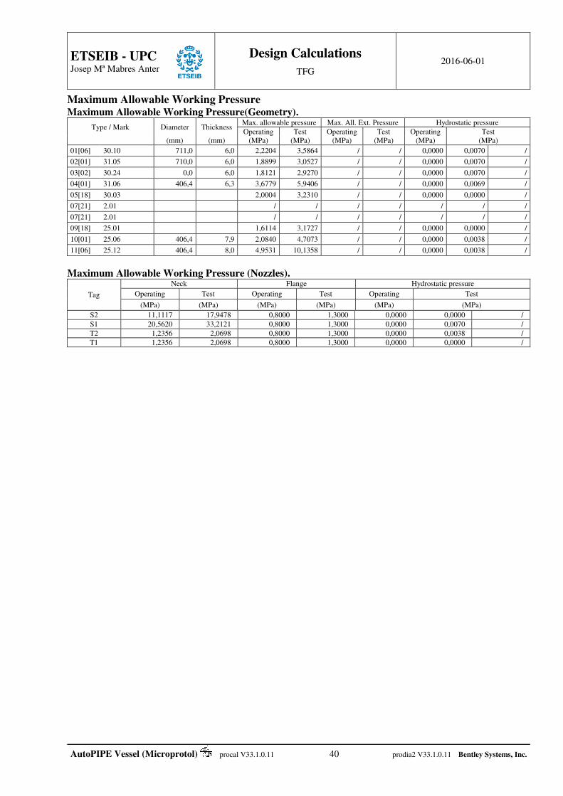
ETSEIB - UPC
Josep Mª Mabres Anter
Design Calculations
TFG 2016-06-01
AutoPIPE Vessel (Microprotol) procal V33.1.0.11 40 prodia2 V33.1.0.11 Bentley Systems, Inc.
Maximum Allowable Working Pressure Maximum Allowable Working Pressure(Geometry).
Type / Mark Diameter Thickness Max. allowable pressure Max. All. Ext. Pressure Hydrostatic pressure
Operating Test Operating Test Operating Test (mm) (mm) (MPa) (MPa) (MPa) (MPa) (MPa) (MPa)
01[06] 30.10 711,0 6,0 2,2204 3,5864 / / 0,0000 0,0070 /
02[01] 31.05 710,0 6,0 1,8899 3,0527 / / 0,0000 0,0070 /
03[02] 30.24 0,0 6,0 1,8121 2,9270 / / 0,0000 0,0070 /
04[01] 31.06 406,4 6,3 3,6779 5,9406 / / 0,0000 0,0069 /
05[18] 30.03 2,0004 3,2310 / / 0,0000 0,0000 /
07[21] 2.01 / / / / / / /
07[21] 2.01 / / / / / / /
09[18] 25.01 1,6114 3,1727 / / 0,0000 0,0000 /
10[01] 25.06 406,4 7,9 2,0840 4,7073 / / 0,0000 0,0038 /
11[06] 25.12 406,4 8,0 4,9531 10,1358 / / 0,0000 0,0038 /
Maximum Allowable Working Pressure (Nozzles).
Tag
Neck Flange Hydrostatic pressure
Operating Test Operating Test Operating Test
(MPa) (MPa) (MPa) (MPa) (MPa) (MPa)
S2 11,1117 17,9478 0,8000 1,3000 0,0000 0,0000 /
S1 20,5620 33,2121 0,8000 1,3000 0,0000 0,0070 /
T2 1,2356 2,0698 0,8000 1,3000 0,0000 0,0038 /
T1 1,2356 2,0698 0,8000 1,3000 0,0000 0,0000 /
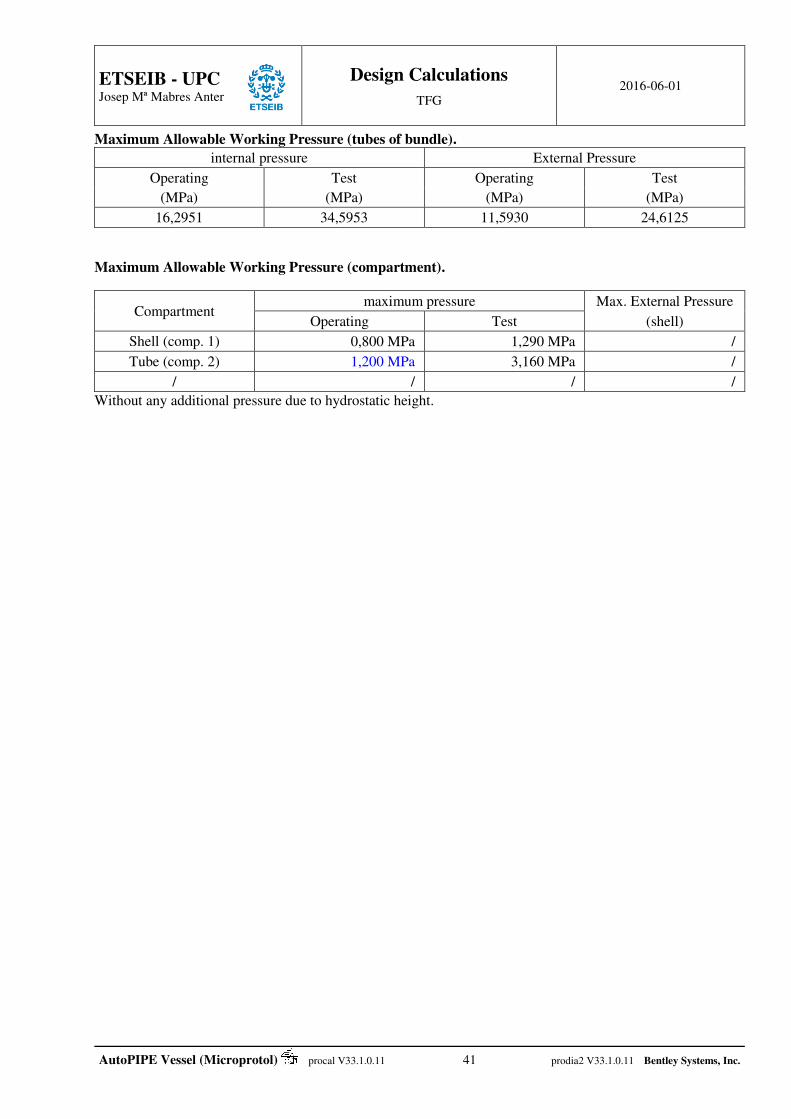
ETSEIB - UPC
Josep Mª Mabres Anter
Design Calculations
TFG 2016-06-01
AutoPIPE Vessel (Microprotol) procal V33.1.0.11 41 prodia2 V33.1.0.11 Bentley Systems, Inc.
Maximum Allowable Working Pressure (tubes of bundle).
internal pressure External Pressure
Operating Test Operating Test
(MPa) (MPa) (MPa) (MPa)
16,2951 34,5953 11,5930 24,6125
Maximum Allowable Working Pressure (compartment).
Compartment maximum pressure Max. External Pressure
Operating Test (shell)
Shell (comp. 1) 0,800 MPa 1,290 MPa /
Tube (comp. 2) 1,200 MPa 3,160 MPa /
/ / / /
Without any additional pressure due to hydrostatic height.
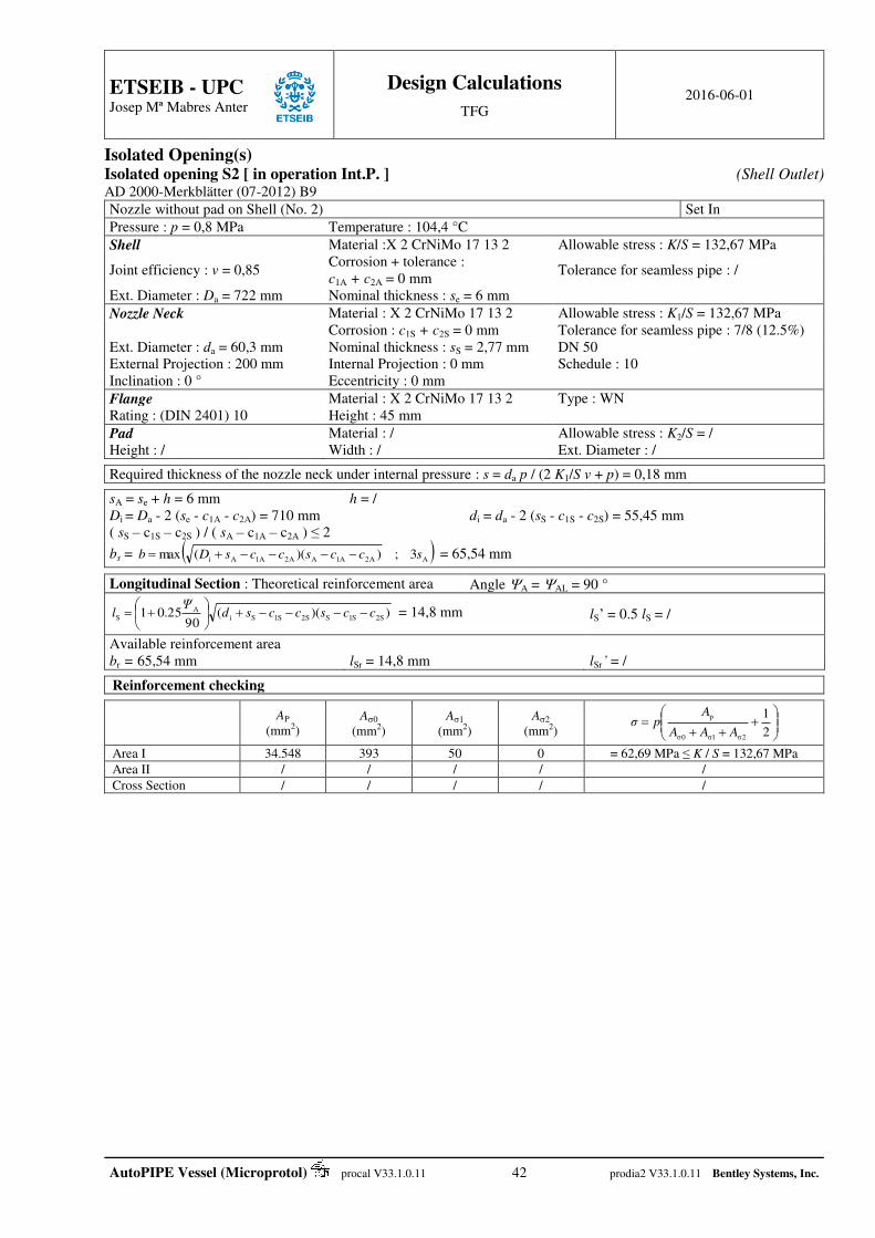
ETSEIB - UPC
Josep Mª Mabres Anter
Design Calculations
TFG 2016-06-01
AutoPIPE Vessel (Microprotol) procal V33.1.0.11 42 prodia2 V33.1.0.11 Bentley Systems, Inc.
Isolated Opening(s) Isolated opening S2 [ in operation Int.P. ] (Shell Outlet) AD 2000-Merkblätter (07-2012) B9
Nozzle without pad on Shell (No. 2) Set In
Pressure : p = 0,8 MPa Temperature : 104,4 °C
Shell Material :X 2 CrNiMo 17 13 2 Allowable stress : K/S = 132,67 MPa
Joint efficiency : v = 0,85 Corrosion + tolerance : c1A + c2A = 0 mm
Tolerance for seamless pipe : /
Ext. Diameter : Da = 722 mm Nominal thickness : se = 6 mm
Nozzle Neck Material : X 2 CrNiMo 17 13 2 Allowable stress : K1/S = 132,67 MPa Corrosion : c1S + c2S = 0 mm Tolerance for seamless pipe : 7/8 (12.5%) Ext. Diameter : da = 60,3 mm Nominal thickness : sS = 2,77 mm DN 50 External Projection : 200 mm Internal Projection : 0 mm Schedule : 10 Inclination : 0 ° Eccentricity : 0 mm
Flange Material : X 2 CrNiMo 17 13 2 Type : WN Rating : (DIN 2401) 10 Height : 45 mm
Pad Material : / Allowable stress : K2/S = / Height : / Width : / Ext. Diameter : /
Required thickness of the nozzle neck under internal pressure : s = da p / (2 K1/S v + p) = 0,18 mm
sA = se + h = 6 mm h = / Di = Da - 2 (se - c1A - c2A) = 710 mm di = da - 2 (sS - c1S - c2S) = 55,45 mm ( sS – c1S – c2S ) / ( sA – c1A – c2A ) ≤ 2
bs = AA2A1AA2A1Ai 3;))((max sccsccsDb = 65,54 mm Longitudinal Section : Theoretical reinforcement area Angle A = AL = 90 °
))((90
25.01 S2S1SS2S1SiA
S ccsccsdΨ
l
= 14,8 mm lS’ = 0.5 lS = /
Available reinforcement area br = 65,54 mm lSr = 14,8 mm lSr’ = /
Reinforcement checking
AP (mm2)
A0 (mm2)
A1 (mm2)
A2 (mm2)
2
1
2σ1σ0σ
p
AAA
Apσ
Area I 34.548 393 50 0 = 62,69 MPa ≤ K / S = 132,67 MPa
Area II / / / / /
Cross Section / / / / /

ETSEIB - UPC
Josep Mª Mabres Anter
Design Calculations
TFG 2016-06-01
AutoPIPE Vessel (Microprotol) procal V33.1.0.11 43 prodia2 V33.1.0.11 Bentley Systems, Inc.
Isolated opening S2 [ in test Int.P. ] (Shell Outlet) AD 2000-Merkblätter (07-2012) B9
Nozzle without pad on Shell (No. 2) Set In
Pressure : p = 1,144 MPa Temperature : 20 °C
Shell Material :X 2 CrNiMo 17 13 2 Allowable stress : K/S = 214,29 MPa
Joint efficiency : v = 0,85 Corrosion + tolerance : c1A + c2A = 0 mm
Tolerance for seamless pipe : /
Ext. Diameter : Da = 722 mm Nominal thickness : se = 6 mm
Nozzle Neck Material : X 2 CrNiMo 17 13 2 Allowable stress : K1/S = 214,29 MPa Corrosion : c1S + c2S = 0 mm Tolerance for seamless pipe : 7/8 (12.5%) Ext. Diameter : da = 60,3 mm Nominal thickness : sS = 2,77 mm DN 50 External Projection : 200 mm Internal Projection : 0 mm Schedule : 10 Inclination : 0 ° Eccentricity : 0 mm
Flange Material : X 2 CrNiMo 17 13 2 Type : WN Rating : (DIN 2401) 10 Height : 45 mm
Pad Material : / Allowable stress : K2/S = / Height : / Width : / Ext. Diameter : /
Required thickness of the nozzle neck under internal pressure : s = da p / (2 K1/S v + p) = 0,16 mm
sA = se + h = 6 mm h = / Di = Da - 2 (se - c1A - c2A) = 710 mm di = da - 2 (sS - c1S - c2S) = 55,45 mm ( sS – c1S – c2S ) / ( sA – c1A – c2A ) ≤ 2
bs = AA2A1AA2A1Ai 3;))((max sccsccsDb = 65,54 mm Longitudinal Section : Theoretical reinforcement area Angle A = AL = 90 °
))((90
25.01 S2S1SS2S1SiA
S ccsccsdΨ
l
= 14,8 mm lS’ = 0.5 lS = /
Available reinforcement area br = 65,54 mm lSr = 14,8 mm lSr’ = /
Reinforcement checking
AP (mm2)
A0 (mm2)
A1 (mm2)
A2 (mm2)
2
1
2σ1σ0σ
p
AAA
Apσ
Area I 34.548 393 50 0 = 89,65 MPa ≤ K / S = 214,29 MPa
Area II / / / / /
Cross Section / / / / /
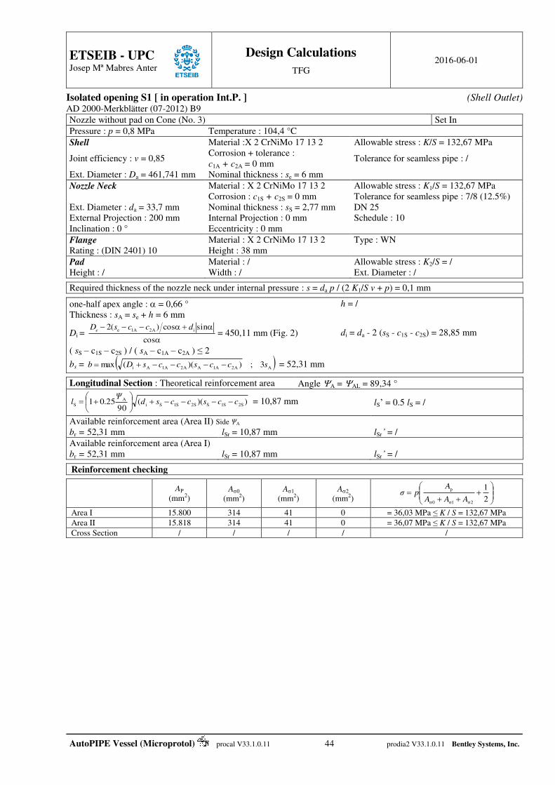
ETSEIB - UPC
Josep Mª Mabres Anter
Design Calculations
TFG 2016-06-01
AutoPIPE Vessel (Microprotol) procal V33.1.0.11 44 prodia2 V33.1.0.11 Bentley Systems, Inc.
Isolated opening S1 [ in operation Int.P. ] (Shell Outlet) AD 2000-Merkblätter (07-2012) B9
Nozzle without pad on Cone (No. 3) Set In
Pressure : p = 0,8 MPa Temperature : 104,4 °C
Shell Material :X 2 CrNiMo 17 13 2 Allowable stress : K/S = 132,67 MPa
Joint efficiency : v = 0,85 Corrosion + tolerance : c1A + c2A = 0 mm
Tolerance for seamless pipe : /
Ext. Diameter : Da = 461,741 mm Nominal thickness : se = 6 mm
Nozzle Neck Material : X 2 CrNiMo 17 13 2 Allowable stress : K1/S = 132,67 MPa Corrosion : c1S + c2S = 0 mm Tolerance for seamless pipe : 7/8 (12.5%) Ext. Diameter : da = 33,7 mm Nominal thickness : sS = 2,77 mm DN 25 External Projection : 200 mm Internal Projection : 0 mm Schedule : 10 Inclination : 0 ° Eccentricity : 0 mm
Flange Material : X 2 CrNiMo 17 13 2 Type : WN Rating : (DIN 2401) 10 Height : 38 mm
Pad Material : / Allowable stress : K2/S = / Height : / Width : / Ext. Diameter : /
Required thickness of the nozzle neck under internal pressure : s = da p / (2 K1/S v + p) = 0,1 mm
one-half apex angle : = 0,66 ° h = /
Thickness : sA = se + h = 6 mm
Di =
cos
sincos)(2 iA2A1e dccsDe = 450,11 mm (Fig. 2) di = da - 2 (sS - c1S - c2S) = 28,85 mm
( sS – c1S – c2S ) / ( sA – c1A – c2A ) ≤ 2
bs = AA2A1AA2A1Ai 3;))((max sccsccsDb = 52,31 mm Longitudinal Section : Theoretical reinforcement area Angle A = AL = 89,34 °
))((90
25.01 S2S1SS2S1SiA
S ccsccsdΨ
l
= 10,87 mm lS’ = 0.5 lS = /
Available reinforcement area (Area II) Side ΨA br = 52,31 mm lSr = 10,87 mm lSr’ = /
Available reinforcement area (Area I) br = 52,31 mm lSr = 10,87 mm lSr’ = /
Reinforcement checking
AP (mm2)
A0 (mm2)
A1 (mm2)
A2 (mm2)
2
1
2σ1σ0σ
p
AAA
Apσ
Area I 15.800 314 41 0 = 36,03 MPa ≤ K / S = 132,67 MPa
Area II 15.818 314 41 0 = 36,07 MPa ≤ K / S = 132,67 MPa
Cross Section / / / / /

ETSEIB - UPC
Josep Mª Mabres Anter
Design Calculations
TFG 2016-06-01
AutoPIPE Vessel (Microprotol) procal V33.1.0.11 45 prodia2 V33.1.0.11 Bentley Systems, Inc.
Isolated opening S1 [ in test Int.P. ] (Shell Outlet) AD 2000-Merkblätter (07-2012) B9
Nozzle without pad on Cone (No. 3) Set In
Pressure : p = 1,151 MPa Temperature : 20 °C
Shell Material :X 2 CrNiMo 17 13 2 Allowable stress : K/S = 214,29 MPa
Joint efficiency : v = 0,85 Corrosion + tolerance : c1A + c2A = 0 mm
Tolerance for seamless pipe : /
Ext. Diameter : Da = 461,741 mm Nominal thickness : se = 6 mm
Nozzle Neck Material : X 2 CrNiMo 17 13 2 Allowable stress : K1/S = 214,29 MPa Corrosion : c1S + c2S = 0 mm Tolerance for seamless pipe : 7/8 (12.5%) Ext. Diameter : da = 33,7 mm Nominal thickness : sS = 2,77 mm DN 25 External Projection : 200 mm Internal Projection : 0 mm Schedule : 10 Inclination : 0 ° Eccentricity : 0 mm
Flange Material : X 2 CrNiMo 17 13 2 Type : WN Rating : (DIN 2401) 10 Height : 38 mm
Pad Material : / Allowable stress : K2/S = / Height : / Width : / Ext. Diameter : /
Required thickness of the nozzle neck under internal pressure : s = da p / (2 K1/S v + p) = 0,09 mm
one-half apex angle : = 0,66 ° h = /
Thickness : sA = se + h = 6 mm
Di =
cos
sincos)(2 iA2A1e dccsDe = 450,11 mm (Fig. 2) di = da - 2 (sS - c1S - c2S) = 28,85 mm
( sS – c1S – c2S ) / ( sA – c1A – c2A ) ≤ 2
bs = AA2A1AA2A1Ai 3;))((max sccsccsDb = 52,31 mm Longitudinal Section : Theoretical reinforcement area Angle A = AL = 89,34 °
))((90
25.01 S2S1SS2S1SiA
S ccsccsdΨ
l
= 10,87 mm lS’ = 0.5 lS = /
Available reinforcement area (Area II) Side ΨA br = 52,31 mm lSr = 10,87 mm lSr’ = /
Available reinforcement area (Area I) br = 52,31 mm lSr = 10,87 mm lSr’ = /
Reinforcement checking
AP (mm2)
A0 (mm2)
A1 (mm2)
A2 (mm2)
2
1
2σ1σ0σ
p
AAA
Apσ
Area I 15.800 314 41 0 = 51,83 MPa ≤ K / S = 214,29 MPa
Area II 15.818 314 41 0 = 51,89 MPa ≤ K / S = 214,29 MPa
Cross Section / / / / /

ETSEIB - UPC
Josep Mª Mabres Anter
Design Calculations
TFG 2016-06-01
AutoPIPE Vessel (Microprotol) procal V33.1.0.11 46 prodia2 V33.1.0.11 Bentley Systems, Inc.
Isolated opening T2 [ in operation Int.P. ] (Channel Outlet) AD 2000-Merkblätter (07-2012) B9
Nozzle without pad on Shell (No. 10) Set In
Pressure : p = 0,8 MPa Temperature : 104,4 °C
Shell Material :P265GH Allowable stress : K/S = 111,73 MPa
Joint efficiency : v = 1 Corrosion + tolerance : c1A + c2A = 4,165 mm
Tolerance for seamless pipe : 7/8 (12.5%)
Ext. Diameter : Da = 406,4 mm Nominal thickness : se = 7,92 mm
Nozzle Neck Material : P265GH Allowable stress : K1/S = 150,67 MPa Corrosion : c1S + c2S = 3,175 mm Tolerance for seamless pipe : 7/8 (12.5%) Ext. Diameter : da = 60,3 mm Nominal thickness : sS = 3,91 mm DN 50 External Projection : 200 mm Internal Projection : 0 mm Schedule : STD Inclination : 0 ° Eccentricity : 0 mm
Flange Material : P265GH Type : WN Rating : (DIN 2401) 10 Height : 45 mm
Pad Material : / Allowable stress : K2/S = / Height : / Width : / Ext. Diameter : /
Required thickness of the nozzle neck under internal pressure : s = da p / (2 K1/S v + p) = 0,16 mm
sA = se + h = 7,92 mm h = / Di = Da - 2 (se - c1A - c2A) = 398,89 mm di = da - 2 (sS - c1S - c2S) = 59,81 mm ( sS – c1S – c2S ) / ( sA – c1A – c2A ) ≤ 2
bs = AA2A1AA2A1Ai 3;))((max sccsccsDb = 38,88 mm Longitudinal Section : Theoretical reinforcement area Angle A = AL = 90 °
))((90
25.01 S2S1SS2S1SiA
S ccsccsdΨ
l
= 4,81 mm lS’ = 0.5 lS = /
Available reinforcement area br = 38,88 mm lSr = 4,81 mm lSr’ = /
Reinforcement checking
AP (mm2)
A0 (mm2)
A1 (mm2)
A2 (mm2)
2
1
2σ1σ0σ
p
AAA
Apσ
Area I 14.024 146 2 0 = 76,02 MPa ≤ K / S = 111,73 MPa
Area II / / / / /
Cross Section / / / / /
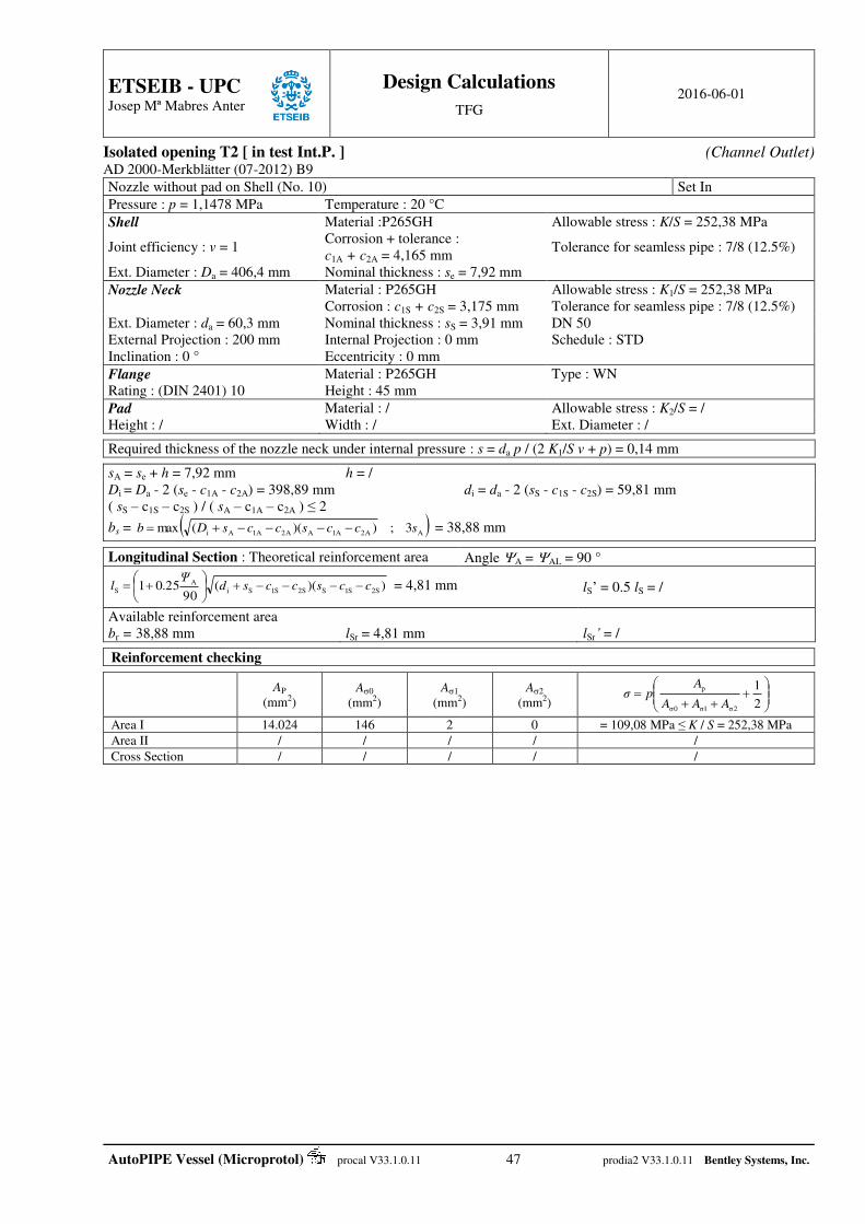
ETSEIB - UPC
Josep Mª Mabres Anter
Design Calculations
TFG 2016-06-01
AutoPIPE Vessel (Microprotol) procal V33.1.0.11 47 prodia2 V33.1.0.11 Bentley Systems, Inc.
Isolated opening T2 [ in test Int.P. ] (Channel Outlet) AD 2000-Merkblätter (07-2012) B9
Nozzle without pad on Shell (No. 10) Set In
Pressure : p = 1,1478 MPa Temperature : 20 °C
Shell Material :P265GH Allowable stress : K/S = 252,38 MPa
Joint efficiency : v = 1 Corrosion + tolerance : c1A + c2A = 4,165 mm
Tolerance for seamless pipe : 7/8 (12.5%)
Ext. Diameter : Da = 406,4 mm Nominal thickness : se = 7,92 mm
Nozzle Neck Material : P265GH Allowable stress : K1/S = 252,38 MPa Corrosion : c1S + c2S = 3,175 mm Tolerance for seamless pipe : 7/8 (12.5%) Ext. Diameter : da = 60,3 mm Nominal thickness : sS = 3,91 mm DN 50 External Projection : 200 mm Internal Projection : 0 mm Schedule : STD Inclination : 0 ° Eccentricity : 0 mm
Flange Material : P265GH Type : WN Rating : (DIN 2401) 10 Height : 45 mm
Pad Material : / Allowable stress : K2/S = / Height : / Width : / Ext. Diameter : /
Required thickness of the nozzle neck under internal pressure : s = da p / (2 K1/S v + p) = 0,14 mm
sA = se + h = 7,92 mm h = / Di = Da - 2 (se - c1A - c2A) = 398,89 mm di = da - 2 (sS - c1S - c2S) = 59,81 mm ( sS – c1S – c2S ) / ( sA – c1A – c2A ) ≤ 2
bs = AA2A1AA2A1Ai 3;))((max sccsccsDb = 38,88 mm Longitudinal Section : Theoretical reinforcement area Angle A = AL = 90 °
))((90
25.01 S2S1SS2S1SiA
S ccsccsdΨ
l
= 4,81 mm lS’ = 0.5 lS = /
Available reinforcement area br = 38,88 mm lSr = 4,81 mm lSr’ = /
Reinforcement checking
AP (mm2)
A0 (mm2)
A1 (mm2)
A2 (mm2)
2
1
2σ1σ0σ
p
AAA
Apσ
Area I 14.024 146 2 0 = 109,08 MPa ≤ K / S = 252,38 MPa
Area II / / / / /
Cross Section / / / / /

ETSEIB - UPC
Josep Mª Mabres Anter
Design Calculations
TFG 2016-06-01
AutoPIPE Vessel (Microprotol) procal V33.1.0.11 48 prodia2 V33.1.0.11 Bentley Systems, Inc.
Isolated opening T1 [ in operation Int.P. ] (Channel inlet) AD 2000-Merkblätter (07-2012) B9
Nozzle without pad on Shell (No. 10) Set In
Pressure : p = 0,8 MPa Temperature : 104,4 °C
Shell Material :P265GH Allowable stress : K/S = 111,73 MPa
Joint efficiency : v = 1 Corrosion + tolerance : c1A + c2A = 4,165 mm
Tolerance for seamless pipe : 7/8 (12.5%)
Ext. Diameter : Da = 406,4 mm Nominal thickness : se = 7,92 mm
Nozzle Neck Material : P265GH Allowable stress : K1/S = 150,67 MPa Corrosion : c1S + c2S = 3,175 mm Tolerance for seamless pipe : 7/8 (12.5%) Ext. Diameter : da = 60,3 mm Nominal thickness : sS = 3,91 mm DN 50 External Projection : 200 mm Internal Projection : 0 mm Schedule : STD Inclination : 0 ° Eccentricity : 0 mm
Flange Material : P265GH Type : WN Rating : (DIN 2401) 10 Height : 45 mm
Pad Material : / Allowable stress : K2/S = / Height : / Width : / Ext. Diameter : /
Required thickness of the nozzle neck under internal pressure : s = da p / (2 K1/S v + p) = 0,16 mm
sA = se + h = 7,92 mm h = / Di = Da - 2 (se - c1A - c2A) = 398,89 mm di = da - 2 (sS - c1S - c2S) = 59,81 mm ( sS – c1S – c2S ) / ( sA – c1A – c2A ) ≤ 2
bs = AA2A1AA2A1Ai 3;))((max sccsccsDb = 38,88 mm Longitudinal Section : Theoretical reinforcement area Angle A = AL = 90 °
))((90
25.01 S2S1SS2S1SiA
S ccsccsdΨ
l
= 4,81 mm lS’ = 0.5 lS = /
Available reinforcement area br = 38,88 mm lSr = 4,81 mm lSr’ = /
Reinforcement checking
AP (mm2)
A0 (mm2)
A1 (mm2)
A2 (mm2)
2
1
2σ1σ0σ
p
AAA
Apσ
Area I 14.024 146 2 0 = 76,02 MPa ≤ K / S = 111,73 MPa
Area II / / / / /
Cross Section / / / / /

ETSEIB - UPC
Josep Mª Mabres Anter
Design Calculations
TFG 2016-06-01
AutoPIPE Vessel (Microprotol) procal V33.1.0.11 49 prodia2 V33.1.0.11 Bentley Systems, Inc.
Isolated opening T1 [ in test Int.P. ] (Channel inlet) AD 2000-Merkblätter (07-2012) B9
Nozzle without pad on Shell (No. 10) Set In
Pressure : p = 1,144 MPa Temperature : 20 °C
Shell Material :P265GH Allowable stress : K/S = 252,38 MPa
Joint efficiency : v = 1 Corrosion + tolerance : c1A + c2A = 4,165 mm
Tolerance for seamless pipe : 7/8 (12.5%)
Ext. Diameter : Da = 406,4 mm Nominal thickness : se = 7,92 mm
Nozzle Neck Material : P265GH Allowable stress : K1/S = 252,38 MPa Corrosion : c1S + c2S = 3,175 mm Tolerance for seamless pipe : 7/8 (12.5%) Ext. Diameter : da = 60,3 mm Nominal thickness : sS = 3,91 mm DN 50 External Projection : 200 mm Internal Projection : 0 mm Schedule : STD Inclination : 0 ° Eccentricity : 0 mm
Flange Material : P265GH Type : WN Rating : (DIN 2401) 10 Height : 45 mm
Pad Material : / Allowable stress : K2/S = / Height : / Width : / Ext. Diameter : /
Required thickness of the nozzle neck under internal pressure : s = da p / (2 K1/S v + p) = 0,14 mm
sA = se + h = 7,92 mm h = / Di = Da - 2 (se - c1A - c2A) = 398,89 mm di = da - 2 (sS - c1S - c2S) = 59,81 mm ( sS – c1S – c2S ) / ( sA – c1A – c2A ) ≤ 2
bs = AA2A1AA2A1Ai 3;))((max sccsccsDb = 38,88 mm Longitudinal Section : Theoretical reinforcement area Angle A = AL = 90 °
))((90
25.01 S2S1SS2S1SiA
S ccsccsdΨ
l
= 4,81 mm lS’ = 0.5 lS = /
Available reinforcement area br = 38,88 mm lSr = 4,81 mm lSr’ = /
Reinforcement checking
AP (mm2)
A0 (mm2)
A1 (mm2)
A2 (mm2)
2
1
2σ1σ0σ
p
AAA
Apσ
Area I 14.024 146 2 0 = 108,71 MPa ≤ K / S = 252,38 MPa
Area II / / / / /
Cross Section / / / / /
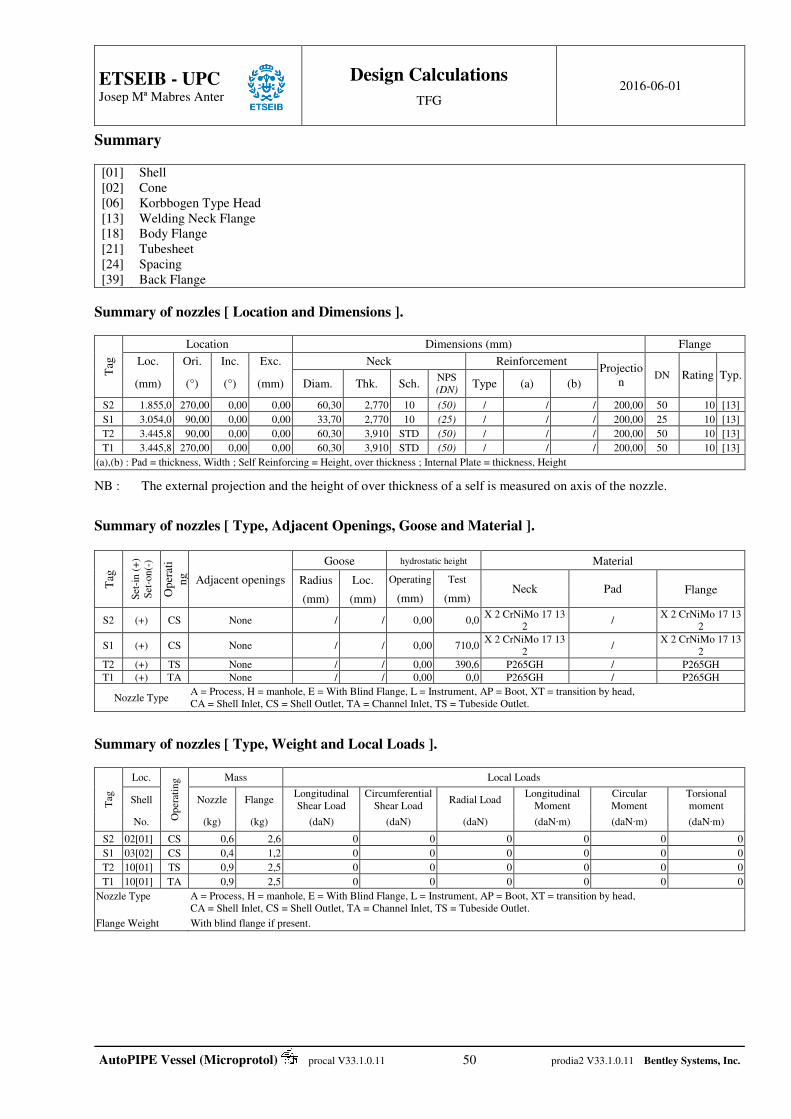
ETSEIB - UPC
Josep Mª Mabres Anter
Design Calculations
TFG 2016-06-01
AutoPIPE Vessel (Microprotol) procal V33.1.0.11 50 prodia2 V33.1.0.11 Bentley Systems, Inc.
Summary
[01] [02] [06] [13] [18] [21] [24] [39]
Shell Cone Korbbogen Type Head Welding Neck Flange Body Flange Tubesheet Spacing Back Flange
Summary of nozzles [ Location and Dimensions ].
Tag
Location Dimensions (mm) Flange
Loc. Ori. Inc. Exc. Neck Reinforcement Projectio
n DN Rating Typ.
(mm) (°) (°) (mm) Diam. Thk. Sch. NPS (DN)
Type (a) (b)
S2 1.855,0 270,00 0,00 0,00 60,30 2,770 10 (50) / / / 200,00 50 10 [13]
S1 3.054,0 90,00 0,00 0,00 33,70 2,770 10 (25) / / / 200,00 25 10 [13]
T2 3.445,8 90,00 0,00 0,00 60,30 3,910 STD (50) / / / 200,00 50 10 [13]
T1 3.445,8 270,00 0,00 0,00 60,30 3,910 STD (50) / / / 200,00 50 10 [13]
(a),(b) : Pad = thickness, Width ; Self Reinforcing = Height, over thickness ; Internal Plate = thickness, Height
NB : The external projection and the height of over thickness of a self is measured on axis of the nozzle.
Summary of nozzles [ Type, Adjacent Openings, Goose and Material ].
Tag
Set
-in
(+
) S
et-o
n(-
)
Op
erat
in
g
Adjacent openings
Goose hydrostatic height Material
Radius Loc. Operating Test Neck Pad Flange
(mm) (mm) (mm) (mm)
S2 (+) CS None / / 0,00 0,0 X 2 CrNiMo 17 13
2 /
X 2 CrNiMo 17 13 2
S1 (+) CS None / / 0,00 710,0 X 2 CrNiMo 17 13
2 /
X 2 CrNiMo 17 13 2
T2 (+) TS None / / 0,00 390,6 P265GH / P265GH
T1 (+) TA None / / 0,00 0,0 P265GH / P265GH
Nozzle Type A = Process, H = manhole, E = With Blind Flange, L = Instrument, AP = Boot, XT = transition by head, CA = Shell Inlet, CS = Shell Outlet, TA = Channel Inlet, TS = Tubeside Outlet.
Summary of nozzles [ Type, Weight and Local Loads ].
Tag
Loc.
Op
erat
ing Mass Local Loads
Shell Nozzle Flange Longitudinal Shear Load
Circumferential Shear Load
Radial Load Longitudinal
Moment Circular Moment
Torsional moment
No. (kg) (kg) (daN) (daN) (daN) (daN∙m) (daN∙m) (daN∙m)
S2 02[01] CS 0,6 2,6 0 0 0 0 0 0
S1 03[02] CS 0,4 1,2 0 0 0 0 0 0
T2 10[01] TS 0,9 2,5 0 0 0 0 0 0
T1 10[01] TA 0,9 2,5 0 0 0 0 0 0
Nozzle Type A = Process, H = manhole, E = With Blind Flange, L = Instrument, AP = Boot, XT = transition by head, CA = Shell Inlet, CS = Shell Outlet, TA = Channel Inlet, TS = Tubeside Outlet.
Flange Weight With blind flange if present.

ETSEIB - UPC
Josep Mª Mabres Anter
Design Calculations
TFG 2016-06-01
AutoPIPE Vessel (Microprotol) procal V33.1.0.11 51 prodia2 V33.1.0.11 Bentley Systems, Inc.
Summaries of bundle. Baffles and Support Plates.
Transverse : No = / Thickness = / Diameter = / Holes = / Total weight = / Material = /
Locations : / Support : No = / Thickness = / Diameter = / Holes = / Total weight = / Material = /
Locations : / Longitudinal : No = / Thickness = / Width = / Total length = / Total weight = / Material = /
(Location , length) : /
Partition Plates.
Front box Total weight = 10,5 kg Material = SA516GR60
Rear box Total weight = / Material = /
Impingement plate, tubes by-pass and sealing strips.
Plate : No = / Thickness = / length = / Material = / Total weight = /
Tubes : No = / Thickness = / Diameter = / Material = / Total weight = /
Sealing Strips : No = / Thickness / Width / Material = / Total weight = /
Sliding Rails.
Quantity = 0 Height / Diameter = / Material = / Type = / Width = / Total weight = /
Tie Rods, spacers and Dummy Tubes.
Bar Stays : No = / Diameter = / Total weight = / Material = /
Spacer : Thk. = / Diameter = / Total weight = / Material = /
Dummy Tubes No = / Diameter = / Total weight = / Material = /
Miscellaneous.
/ No = / Thickness = / Total weight = / Material = /
Summary of bends.
Row Number of bends
Weight Thickness Bending radius Straight Length Circumferential
Length
1 9 6,2 kg 2,11 mm 38,10 mm 2.500,00 mm 5.119,69 mm
2 8 6,3 kg 2,11 mm 65,60 mm 2.500,00 mm 5.206,08 mm
3 7 6,4 kg 2,11 mm 93,09 mm 2.500,00 mm 5.292,46 mm
4 4 6,6 kg 2,11 mm 120,59 mm 2.500,00 mm 5.378,84 mm Total number of bends = 28 Total weight = 178,3 kg
Length ( thk = 2,11 mm ) = 146,3 m
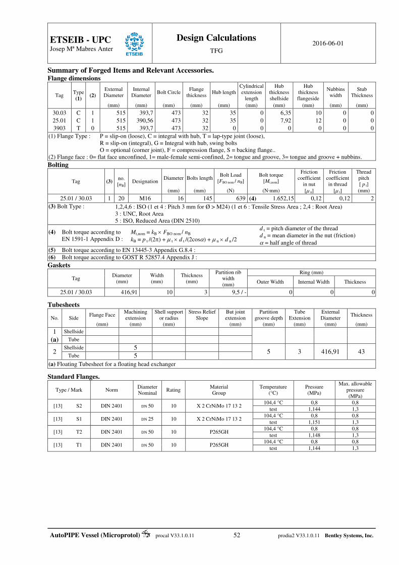
ETSEIB - UPC
Josep Mª Mabres Anter
Design Calculations
TFG 2016-06-01
AutoPIPE Vessel (Microprotol) procal V33.1.0.11 52 prodia2 V33.1.0.11 Bentley Systems, Inc.
Summary of Forged Items and Relevant Accessories. Flange dimensions
Tag Type (1)
(2) External Diameter
Internal Diameter
Bolt Circle Flange
thickness Hub length
Cylindrical extension
length
Hub thickness shellside
Hub thickness flangeside
Nubbins width
Stub Thickness
(mm) (mm) (mm) (mm) (mm) (mm) (mm) (mm) (mm) (mm)
30.03
25.01
3903
C
C
T
1
1
0
515
515
515
393,7
390,56
393,7
473
473
473
32
32
32
35
35
0
0
0
0
6,35
7,92
0
10
12
0
0
0
0
0
0
0
(1) Flange Type : P = slip-on (loose), C = integral with hub, T = lap-type joint (loose), R = slip-on (integral), G = Integral with hub, swing bolts O = optional (corner joint), F = compression flange, S = backing flange.. (2) Flange face : 0= flat face unconfined, 1= male-female semi-confined, 2= tongue and groove, 3= tongue and groove + nubbins.
Bolting
Tag (3) no. [nB]
Designation Diameter Bolts length
Bolt Load [FBO nom / nB]
Bolt torque [Mt,nom]
Friction coefficient
in nut
[ n]
Friction coefficient in thread
[ t]
Thread pitch [ p t]
(mm) (mm) (N) (N∙mm) (mm)
25.01 / 30.03 1 20 M16 16 145 639 (4) 1.652,15 0,12 0,12 2
(3) Bolt Type : 1,2,4,6 : ISO (1 et 4 : Pitch 3 mm for Ø > M24) (1 et 6 : Tensile Stress Area ; 2,4 : Root Area) 3 : UNC, Root Area 5 : ISO, Reduced Area (DIN 2510)
(4) Bolt torque according to EN 1591-1 Appendix D :
Mt,nom = kB FBO nom / nB
kB = p t /(2) + t d t /(2cos) + n d n /2
d t = pitch diameter of the thread d n = mean diameter in the nut (friction)
= half angle of thread
(5) Bolt torque according to EN 13445-3 Appendix G.8.4 :
(6) Bolt torque according to GOST R 52857.4 Appendix J :
Gaskets
Tag Diameter
(mm) Width (mm)
Thickness (mm)
Partition rib width (mm)
Ring (mm)
Outer Width Internal Width Thickness
25.01 / 30.03 416,91 10 3 9,5 / - 0 0 0 Tubesheets
No. Side Flange Face
Machining extension
Shell support or radius
Stress Relief Slope
But joint extension
Partition groove depth
Tube Extension
External Diameter
Thickness
(mm) (mm) (mm) (mm) (mm) (mm) (mm) (mm)
1 (a)
Shellside
Tube
2 Shellside 5
5 3 416,91 43 Tube 5
(a) Floating Tubesheet for a floating head exchanger Standard Flanges.
Type / Mark Norm Diameter Nominal
Rating Material Group
Temperature (°C)
Pressure (MPa)
Max. allowable pressure (MPa)
[13] S2 DIN 2401 DN 50 10 X 2 CrNiMo 17 13 2 104,4 °C 0,8 0,8
test 1,144 1,3
[13] S1 DIN 2401 DN 25 10 X 2 CrNiMo 17 13 2 104,4 °C 0,8 0,8
test 1,151 1,3
[13] T2 DIN 2401 DN 50 10 P265GH 104,4 °C 0,8 0,8
test 1,148 1,3
[13] T1 DIN 2401 DN 50 10 P265GH 104,4 °C 0,8 0,8
test 1,144 1,3
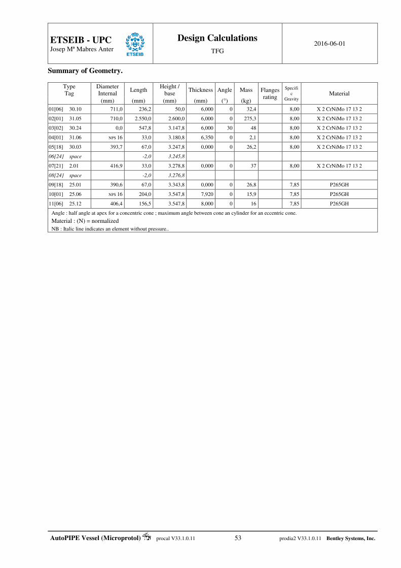
ETSEIB - UPC
Josep Mª Mabres Anter
Design Calculations
TFG 2016-06-01
AutoPIPE Vessel (Microprotol) procal V33.1.0.11 53 prodia2 V33.1.0.11 Bentley Systems, Inc.
Summary of Geometry.
Type Tag
Diameter Internal
Length Height /
base Thickness Angle Mass Flanges
rating
Specific
Gravity Material
(mm) (mm) (mm) (mm) (°) (kg)
01[06] 30.10 711,0 236,2 50,0 6,000 0 32,4 8,00 X 2 CrNiMo 17 13 2
02[01] 31.05 710,0 2.550,0 2.600,0 6,000 0 275,3 8,00 X 2 CrNiMo 17 13 2
03[02] 30.24 0,0 547,8 3.147,8 6,000 30 48 8,00 X 2 CrNiMo 17 13 2
04[01] 31.06 NPS 16 33,0 3.180,8 6,350 0 2,1 8,00 X 2 CrNiMo 17 13 2
05[18] 30.03 393,7 67,0 3.247,8 0,000 0 26,2 8,00 X 2 CrNiMo 17 13 2
06[24] space -2,0 3.245,8
07[21] 2.01 416,9 33,0 3.278,8 0,000 0 37 8,00 X 2 CrNiMo 17 13 2
08[24] space -2,0 3.276,8
09[18] 25.01 390,6 67,0 3.343,8 0,000 0 26,8 7,85 P265GH
10[01] 25.06 NPS 16 204,0 3.547,8 7,920 0 15,9 7,85 P265GH
11[06] 25.12 406,4 156,5 3.547,8 8,000 0 16 7,85 P265GH
Angle : half angle at apex for a concentric cone ; maximum angle between cone an cylinder for an eccentric cone.
Material : (N) = normalized
NB : Italic line indicates an element without pressure..
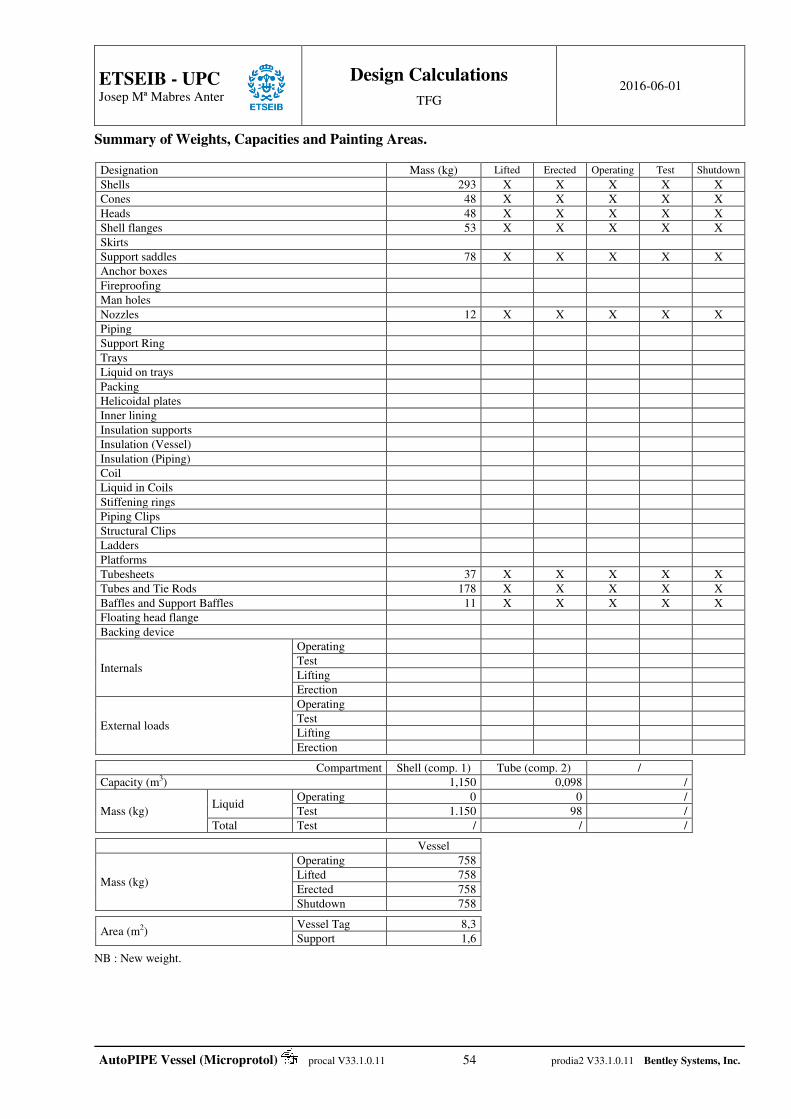
ETSEIB - UPC
Josep Mª Mabres Anter
Design Calculations
TFG 2016-06-01
AutoPIPE Vessel (Microprotol) procal V33.1.0.11 54 prodia2 V33.1.0.11 Bentley Systems, Inc.
Summary of Weights, Capacities and Painting Areas.
Designation Mass (kg) Lifted Erected Operating Test Shutdown
Shells 293 X X X X X
Cones 48 X X X X X
Heads 48 X X X X X
Shell flanges 53 X X X X X
Skirts
Support saddles 78 X X X X X
Anchor boxes
Fireproofing
Man holes
Nozzles 12 X X X X X
Piping
Support Ring
Trays
Liquid on trays
Packing
Helicoidal plates
Inner lining
Insulation supports
Insulation (Vessel)
Insulation (Piping)
Coil
Liquid in Coils
Stiffening rings
Piping Clips
Structural Clips
Ladders
Platforms
Tubesheets 37 X X X X X
Tubes and Tie Rods 178 X X X X X
Baffles and Support Baffles 11 X X X X X
Floating head flange
Backing device
Internals
Operating
Test
Lifting
Erection
External loads
Operating
Test
Lifting
Erection
Compartment Shell (comp. 1) Tube (comp. 2) /
Capacity (m3) 1,150 0,098 /
Mass (kg) Liquid
Operating 0 0 /
Test 1.150 98 /
Total Test / / /
Vessel
Mass (kg)
Operating 758
Lifted 758
Erected 758
Shutdown 758
Area (m2) Vessel Tag 8,3
Support 1,6 NB : New weight.
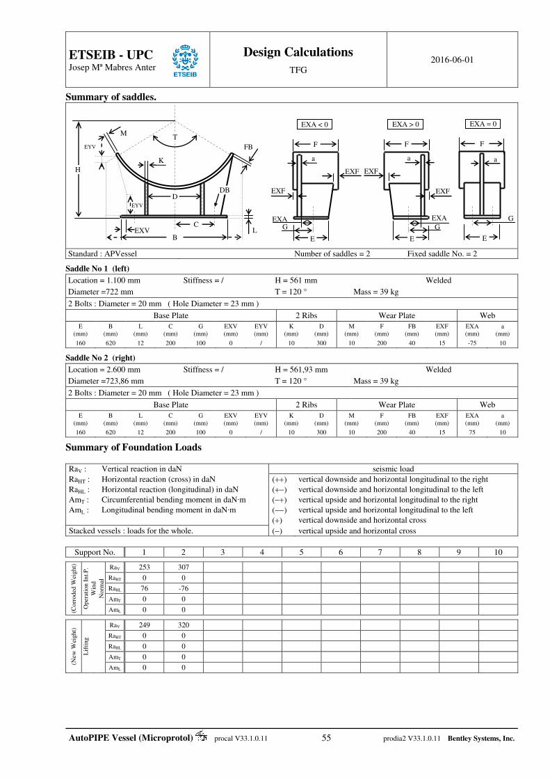
ETSEIB - UPC
Josep Mª Mabres Anter
Design Calculations
TFG 2016-06-01
AutoPIPE Vessel (Microprotol) procal V33.1.0.11 55 prodia2 V33.1.0.11 Bentley Systems, Inc.
Summary of saddles.
Standard : APVessel Number of saddles = 2 Fixed saddle No. = 2 Saddle No 1 (left)
Location = 1.100 mm Stiffness = / H = 561 mm Welded
Diameter =722 mm T = 120 ° Mass = 39 kg
2 Bolts : Diameter = 20 mm ( Hole Diameter = 23 mm )
Base Plate 2 Ribs Wear Plate Web
E (mm)
B (mm)
L (mm)
C (mm)
G (mm)
EXV (mm)
EYV (mm)
K (mm)
D (mm)
M (mm)
F (mm)
FB (mm)
EXF (mm)
EXA (mm)
a (mm)
160 620 12 200 100 0 / 10 300 10 200 40 15 -75 10 Saddle No 2 (right)
Location = 2.600 mm Stiffness = / H = 561,93 mm Welded
Diameter =723,86 mm T = 120 ° Mass = 39 kg
2 Bolts : Diameter = 20 mm ( Hole Diameter = 23 mm )
Base Plate 2 Ribs Wear Plate Web
E (mm)
B (mm)
L (mm)
C (mm)
G (mm)
EXV (mm)
EYV (mm)
K (mm)
D (mm)
M (mm)
F (mm)
FB (mm)
EXF (mm)
EXA (mm)
a (mm)
160 620 12 200 100 0 / 10 300 10 200 40 15 75 10 Summary of Foundation Loads RaV : Vertical reaction in daN seismic load
RaHT : Horizontal reaction (cross) in daN () vertical downside and horizontal longitudinal to the right
RaHL : Horizontal reaction (longitudinal) in daN () vertical downside and horizontal longitudinal to the left
AmT : Circumferential bending moment in daN∙m () vertical upside and horizontal longitudinal to the right
AmL : Longitudinal bending moment in daN∙m () vertical upside and horizontal longitudinal to the left
() vertical downside and horizontal cross
Stacked vessels : loads for the whole. () vertical upside and horizontal cross
Support No. 1 2 3 4 5 6 7 8 9 10
(Corr
oded
Wei
ght)
Oper
atio
n I
nt.
P.
Win
d
Norm
al
RaV 253 307
RaHT 0 0
RaHL 76 -76
AmT 0 0
AmL 0 0
(New
Wei
ght)
Lif
ting
RaV 249 320
RaHT 0 0
RaHL 0 0
AmT 0 0
AmL 0 0
a
EXA
F
E
EXA < 0
G
EXF
EXF
a
EXA
F
E
EXA > 0
G
EXF
EXF
a
G
F
E
EXA = 0
D
K
B
C L
H
M
FB
EXV
EYV
DB
EYV
T
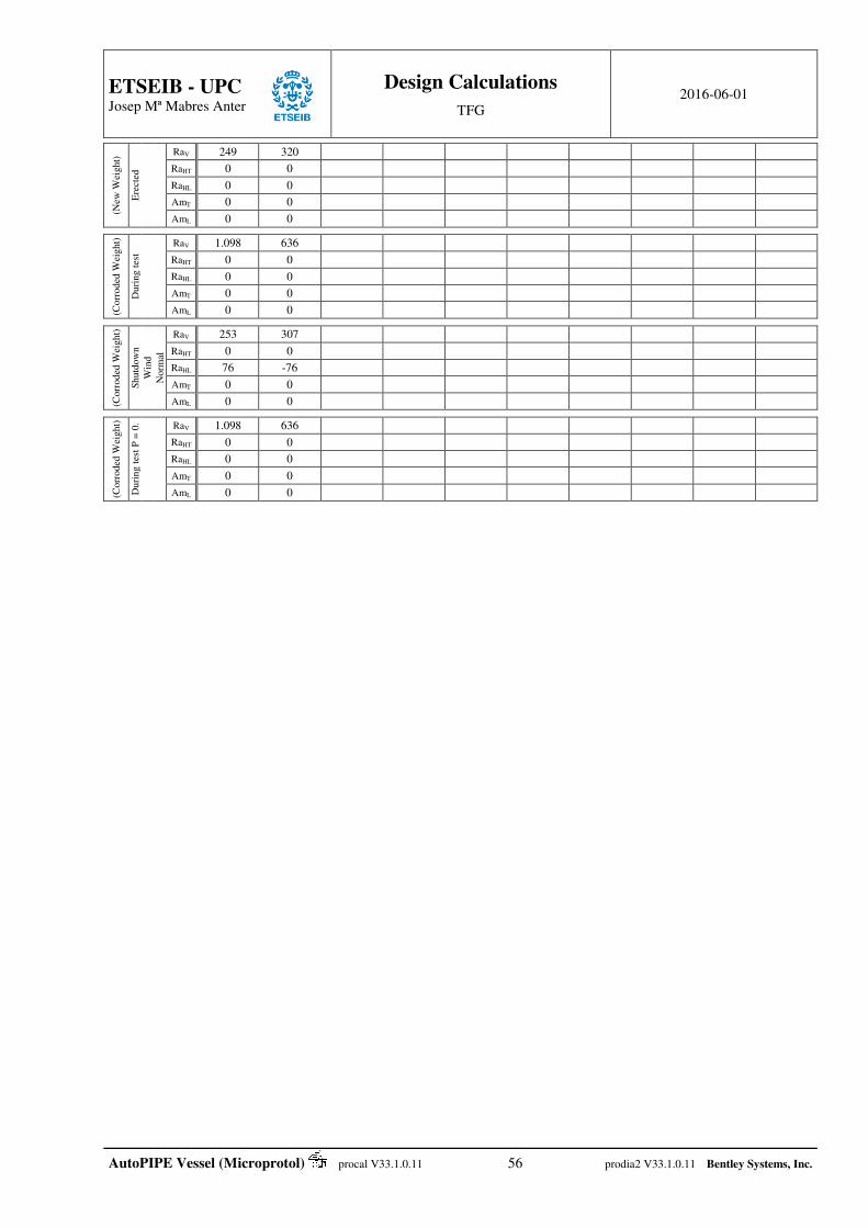
ETSEIB - UPC
Josep Mª Mabres Anter
Design Calculations
TFG 2016-06-01
AutoPIPE Vessel (Microprotol) procal V33.1.0.11 56 prodia2 V33.1.0.11 Bentley Systems, Inc.
(New
Wei
ght)
Ere
cted
RaV 249 320
RaHT 0 0
RaHL 0 0
AmT 0 0
AmL 0 0
(Corr
oded
Wei
ght)
Duri
ng t
est
RaV 1.098 636
RaHT 0 0
RaHL 0 0
AmT 0 0
AmL 0 0
(Corr
oded
Wei
ght)
Shutd
ow
n
Win
d
Norm
al
RaV 253 307
RaHT 0 0
RaHL 76 -76
AmT 0 0
AmL 0 0
(Co
rroded
Wei
ght)
Du
ring t
est
P =
0.
RaV 1.098 636
RaHT 0 0
RaHL 0 0
AmT 0 0
AmL 0 0