curtain wall issues, problems and solutions
TRANSCRIPT
CURTAIN WALL ISSUES, PROBLEMS,AND SOLUTIONS
KARIM P. ALLANA, RRC, RWC, PE; ANDDON CARTER
ALLANA BUICK & BERS, INC.990 Commercial Street, Palo Alto, CA 94303
Phone: 650-543-5638 • Fax: 650-354-8828 • E-mail: [email protected]
S Y M P O S I U M O N B U I L D I N G E N V E L O P E T E C H N O L O G Y • O C T O B E R 2 0 1 2 A L L A N A • 9 7

ABSTRACT
Curtain walls are taken for granted, even by design professionals. All curtain wall sys-tems and materials present unique challenges in appearance, design, installation, mainte-nance, and repair. These issues will be addressed by the presenter with real-life, practicalexamples backed by engineering expertise. The primary focus will be glass curtain walls andwindow walls, including failures. The presentation is based on the authors’ case studies ofthe failures of curtain walls, windows, sealants, and flashings, providing useful informationon design failures and testing. Included are definitions of curtain wall types, various sys-tems and components, and differences between stick and unitized curtain walls.
SPEAKER
KARIM P. ALLANA, RRC, RWC, PE — ALLANA BUICK & BERS, INC.
With more than 25 years of experience in construction engineering, forensic investiga-tion, and design, KARIM ALLANA, RRC, RWC, PE, is CEO and senior principal of AllanaBuick & Bers, Inc. He earned his BS in civil engineering from Santa Clara University and isa licensed professional engineer in California, Hawaii, Nevada, and Washington. Allana hasbeen in the AE and construciton fields for over 30 years, specializing in forensic analysisand sustainable construction of roofing, waterproofing, and the building envelope. He hasacted as a consultant and expert witness in 200-plus construction defect projects and is afrequent speaker and presenter at professional forums.
NONPRESENTING COAUTHOR
DON CARTER — ALLANA BUICK & BERS, INC.
A senior curtain wall consultant with Allana Buick & Bers, DON CARTER has more than45 years of experience in the assessment, design, and construction administration of store-front, curtain walls, and glazing systems. Carter was previously a senior consultant withIBA Consultants and worked on the majority of high rises built in the greater Miami areasince 1995. Prior to that, he was a test engineer with a construction research laboratory anda project manager with Permastellisa Group (formerly Glassalum International).
9 8 • A L L A N A S Y M P O S I U M O N B U I L D I N G E N V E L O P E T E C H N O L O G Y • O C T O B E R 2 0 1 2

S Y M P O S I U M O N B U I L D I N G E N V E L O P E T E C H N O L O G Y • O C T O B E R 2 0 1 2 A L L A N A • 9 9
INTRODUCTIONCurtain wall design and installation can
be taken for granted, even by architects,engineers, and experienced contractors.However, all curtain wall systems and mate-rials present unique challenges in appear-ance, design, installation, maintenance,and repair. These issues and potential prob-lems will be addressed in this paper, withreal-life, practical examples backed by engi-neering expertise.
The paper is based on the authors’ casestudies of the failures of curtain walls, win-dows, sealants, and flashings, providinguseful information on design failures andtesting. Included are definitions of curtainwall types, various systems and compo-nents, and differences between stick andunitized curtain walls. Included is anoverview of curtain wall types, definitions ofvarious systems and components, and dif-ferences between curtain walls, windowwalls, and storefronts. Testing, design stan-dards, and the use of mock-ups are woventhroughout the presentation.
Curtain walls consist of many materialsfound in high-rise steel or concrete build-ings and even two-story wood-framed build-ings. Typical curtain wall materials includethe following:
• Aluminum extrusions are the load-bearing element of most moderncurtain wall systems and are avail-able in different alloys as the designloads and safety factors require.
• Glass (vision and spandrel)• Aluminum panels in sheet, plate or
aluminum composites• Stone—typically granite—due to its
superior resistance to wind load com-pared to marble or other products
• Glass-fiber-reinforced concrete (GFRC)panels
• Louvers• Operable windows
Each type of curtain wall system ormaterial presents its own unique appear-ance, design, installation, maintenance,and repair challenges, to be addressed bythe author. The primary focus will be glass
curtain walls; however,window walls, windows,and storefront systemsare also covered.
As architecturalappeal and applicationshave increased, thecomplexities of dealingwith energy usage dy-namics, rain and wind,and durability have be-come ever more difficultfor the designer. Theauthor reviews the im-plication of differentstyles, materials, man-ufacturers, and instal-lation methods.
DEFINITION ANDDESCRIPTION OFCURTAIN WALLSYSTEMS
A curtain wall is theexterior façade of abuilding that 1) spanstwo or more floors inheight; and 2) is non-structural, i.e., does notsupport any loadsexcept for its own gravi-ty load, while transfer-ring wind and other loads to the buildingstructure via connections to each floor,columns, or the roof. Thus, “curtain”implies that the wall is hung from the build-ing’s structural frame, generally the edge ofthe slab.
Curtain walls, as well as other exteriorglazing systems must be properly designedto address the following:
• Structural integrity• Movement (thermal, seismic, and
differential)• Weathertightness• Condensation• Thermal insulation (curtain walls
only)• Firesafing (curtain walls only)
Other project- or site-specific considera-
tions such as the following need to beaddressed:
• Sound transmission• Hurricane-borne debris resistance• Bomb blast resistance
See Figure 1.As the curtain wall is mostly nonstruc-
tural, it can be made of a lightweight mate-rial, reducing construction costs throughstandardization of installation, fast-trackmethods, and reduced load on the buildingframe, leading to lower structural costs.Another great advantage is that when glassis used as the curtain wall, natural light canpenetrate into the building.
Curtain wall frames are commonlyinfilled with glass but can be infilled withstone veneer, metal panels, operable vents,
CURTAIN WALL ISSUES, PROBLEMS,AND SOLUTIONS
Figure 1 – Exposed view of curtain wall components.

and other components.Today, curtain wall systems are typically designed with extruded
aluminum members, although the first curtain walls were made ofsteel.
THE BASIC GLAZING SYSTEMSCurtain Wall
Prefab or assembled units attached to the structure as describedpreviously. Recent improvements in design do not require “dropping”the building from a swing stage to install sealants. Older designsrequired this expensive last step to weatherproofing the joinerybetween pre-assembled units.
Window WallHorizontal bands (ribbons) of fixed/operable windows, today most-
ly factory-assembled and glazed; connected between floors or otherstructural elements such as precast concrete.
WindowsIndividual units—fixed or operable—set in a wall. These are some-
times referred to as punched windows, connected to studframing, CMU, or precast concrete.
StorefrontTypically stick-built floor to ceiling, include entrance doors
and vestibules. Field installed from the floor; frames first, thenglass placed in the frame. Note that storefronts may containoperable windows but should not be used at elevations toohigh above the first floor, due to their relatively weak struc-tural capacity. Note that a monumental lobby or entrance withclear vertical spans over 12 ft. will require a stronger—i.e.,deeper—structural member in order to resist wind loads.
BRIEF HISTORY OF CURTAIN WALLSCurtain Walls Through History
The oldest curtain walls consisted of many different typesof materials: thick masonry, brick, terra cotta, and wood. Thelimitation on all these materials was weight, seriously limitingthe height to which they could be built. The other limitation onthese older types of curtain walls was that not much lightcould penetrate. Prior to the middle of the nineteenth century,buildings were constructed with the exterior walls of the build-ing, typically masonry supporting the load of the entire struc-ture. The development and widespread use of structural steel(and later, reinforced concrete) allowed relatively smallcolumns to support large loads. Grad-ually, designers wereable to determine how to design exterior walls to be nonload-bearing and thus much lighter and more open. This allowedincreased use of glass as an exterior façade and the modern-day curtain wall.
Glass Curtain Walls in the United StatesThe first glass curtain wall in the United States reportedly
was designed by the architect Louis S. Curtiss and installed in1909 in Kansas City on the Boley Clothing Company building.That building is now listed on the National Register of HistoricPlaces and is still in use (Figure 2).
Another building that is sometimes credited as being thefirst glass curtain wall building, the Hallidie building in San
Figure 3 – Hallidie building, San Francisco, CA. Source:WorldArchitectureMap.org and Wikipedia.
Figure 2 – Boley Clothing Company building, Kansas City,MO. Source: Wikipedia.
1 0 0 • A L L A N A S Y M P O S I U M O N B U I L D I N G E N V E L O P E T E C H N O L O G Y • O C T O B E R 2 0 1 2

Francisco, which was constructed nineyears later in 1918, is still in operation andhouses the Northern California Chapter ofthe American Institute of Architects (AIA).Although not the first glass curtain wallbuilding, it is a good example of a modernistbuilding with a curtain wall (Figure 3). Notethe steel mullions (vertical members) andother support members. Glass was typical-ly held in place with clips and weather-proofed with glazing compound.
The first curtain wall installed in NewYork City, in the Lever House building(Skidmore, Owings, and Merrill, 1952), wasa major innovation in the extensive use ofsteel mullions (Figure 4).
In the 1960s, there was the first wide-spread use of aluminum extrusions forload-bearing mullions. Aluminum offers theunique advantage of being able to be easilyextruded into nearly any shape required fordesign and aesthetic purposes. Customshapes can be designed and manufacturedwith relative ease, although each newdesign brings new complexities in installa-tion, testing, and maintenance, discussedlater in this article.
Granite-Clad Curtain Walls in the U.S.Figure 5 depicts the Bell Atlantic Tower
in Philadelphia, clad in glass and 65% gran-ite. The stone for this 500,000-sq.-ft. cur-tain wall was quarried in Sweden, thenshipped in blocks to Italy, where it wasfabricated into 3-cm-thick infill panelswith polished, honed, and flamed finish-es. The granite panels were then shippedto Miami, installed into 10,500 unitizedpanels, and shipped to Philadelphia byflatbed trailers, where floors 3 through42 were wrapped in curtain wall at therate of two floors per week.
Other Curtain Walls Around theWorld
Two other unique examples of cur-tain walls are the Torre Mayor buildingin Mexico City and the Espirito SantoPlaza, an office building in Miami. Thefirst building, shown in Figure 6, mea-sures 738 ft., consisting of 55 stories.Due to Mexico City’s location in a knownearthquake area, it was designed towithstand an earthquake measuring 9on the Richter Scale. It was built with 96hydraulic dampers installed diagonallyin the elevator shafts, perpendicular tothe diamond or X-patterned bracingsteel faintly visible through the convex
Figure 6 – Torre Mayor building,Mexico City. Source: Teratec, Inc.
Figure 4 –Lever House,New YorkCity. Source:Wikipedia.
Figure 5 –Bell Atlantic
Tower,Philadelphia,
PA. Source:Building
Design andConstruction
Magazine.
S Y M P O S I U M O N B U I L D I N G E N V E L O P E T E C H N O L O G Y • O C T O B E R 2 0 1 2 A L L A N A • 1 0 1

façade in Figure 6. In January 2003, a 7.6magnitude earthquake shook Mexico City,but the building was not damaged, andmany occupants were unaware of thequake. This curtain wall provided designchallenges due to sloped and reverse-slopeglazing and the building face curvature,achieved with segmented panels.
Figure 7 is a photo of the Espirito SantoBuilding, the 36-story Miami building, thearchitecture of which is based loosely onthe Saint Louis Arch. Design and installa-tion challenges faced in this building alsoincluded sloped glazing, the conical façade,hundreds of custom extrusions, a very largenumber of complicated construction de-tails, thousands of fabrication documentsheets, and extensive laboratory testing,including large- and small-missile impact.Design wind loads for the curtain wall were+140/-180 psf. The design and construc-tion of this building was aided by 3-D mod-eling.
TYPES OF CURTAIN WALL SYSTEMSStick Systems
The original glass curtain wall structur-al framing was hot-rolled steel sections,erected in piece-by-piece fashion or in“sticks.” As noted previously, the use of
steel sections—highly sus-ceptible to rust—was aban-doned in favor of tubularaluminum extrusions. Notonly is aluminum “rust-proof,” it can be easilyextruded into more complexshapes than would be possi-ble with steel. The improvedweatherability of aluminum,combined with this ability toaddress complex architec-tural detailing, has made itthe material of choice today.See Figure 8.
Stick system assembliestend to be a more attractivesystem for smaller two- tothree-story jobs becausedelivery is quicker and thesystems are more afford-able. Installers need to takeinto consideration that allthe critical joints are sealedat the jobsite and may besubject to dirt, wind, andother environmental conta-minants. However, there aresome disadvantages to the
stick-built installation of curtain walls:• Thermal movement joints. The main
load-bearing vertical mullions arenormally installed in lengths span-ning two floors, with splice jointsnecessarily occurring in the glazed
areas—typically the spandrel glaz-ing. On a typical 2.5-in. system,glazed with insulated glass, the edge-clearance requirements for the glass,plus frame fabrication tolerance andglass size tolerance, translate into amaximum 0.5-in. splice joint. Whenthe +50% movement capacity of thesilicone sealant in the joint is fac-tored into the equation, the resultingtotal movement that the 0.5-in. jointcan accommodate is +0.25 inch.Thus, for this 2.5-in.-face-dimen-sion, off-the-shelf standard system(spanning two 12.5-ft. floors, withthermal expansion and contractionat the industry-standard 180ºF sur-face temperature), the thermal move-ment is approximately 0.1875 of aninch, leaving only .0625 in. for othertolerances, such as fabrication anderection.
• Differential floor live-load deflec-tions/axial shortening of steelcolumns on high rises due to gravityload, or long-term creep of high-riseconcrete structures due to sus-tained gravity loads. The typical 2.5-in. face dimension standard sys-tems, as demonstrated above, can-not factor these movements into the0.5-in. thermal expansion jointevery 25 ft. These added movementsare generally calculated by thestructural engineer to fall between
Figure 7 – Espirito Santo Building, Miami. Noteconical shape and complexity of building face.Source: Viracon, Inc.
Figure 8 – Stick assembly under construction.
1 0 2 • A L L A N A S Y M P O S I U M O N B U I L D I N G E N V E L O P E T E C H N O L O G Y • O C T O B E R 2 0 1 2
Expansion Joints
0.1250 and 0.25 in. This is one rea-son why typical double-span, 2.5-in.stick systems are acknowledged byresponsible manufacturers as notbeing applicable to high-rise build-ings. Designers and end-users alikeshould recognize all movements, in-cluding seismic, which could provedetrimental to the wall’s long-termperformance. (Note: If the designerallows for double horizontal,caulked stack joints every 25 ft.,then this type of system could beengineered to handle many types ofmovements, not including seismicmovements.)
• Lateral seismic displacement vs.glass breakage. The stick system,having tubular vertical mullions, canonly accommodate lateral displace-ment of the glass openings withinthe glass rabbet or pocket. The glassmust float within the pockets whenthe original square or rectangular-shaped opening becomes trapezoidalin the displaced position, withoutmaking contact with the mullions.Also note that should any floor becantilevered, a vertical component ofseismic displacement has been intro-duced that must now be considered.In the 2006 IBC, there is a require-ment that no glass fall out of a build-ing during a seismic event. Thedesigner must:
— Minimize the height of the tallestlite of glass
— Increase the mullion face dimen-sions
— Specify all glass to be heat-strengthened or annealed, lami-nated glass having one face ad-hered to the frame (one face ofeach laminated lite in a double-laminated insulated glass unit[IGU]) with a silicone sealant
The standard sticksystem cannot meetthis code requirementin Zone 4 when theseismic drift is H/50(H = height) or 2% andthe nonlaminatedglass height is >5.5 ft.Note that at H/50, a12.5-ft. floor spacingwill yield a 3-in. later-al displacement ateach succeeding floor.
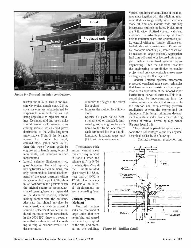
Unitized Systems(Modular)
Unitized curtainwalls are composed oflarge units that areassembled and glazedin the factory, shippedto the site, and erect-ed on the building.
Vertical and horizontal mullions of the mod-ules mate together with the adjoining mod-ules. Modules are generally constructed onestory tall and one module wide but mayincorporate multiple modules. Typical unitsare 5 ft. wide. Unitized curtain walls canalso have the advantages of speed, lowerfield installation costs, and enhanced qual-ity control within an interior climate con-trolled fabrication environment. Considera-ble economic benefits (i.e., lower costs canbe realized on larger projects). Appropriatelead time will need to be factored into a pro-ject timeline, as unitized systems requireengineering. Often the additional cost forthe engineering is prohibitive to smallerprojects and only economically makes senseon larger projects. See Figure 9.
Modern unitized systems incorporatepressured-equalized rain screen principlesthat have enhanced resistance to rain pen-etration via separation of the inboard vaporbarrier from the wetted surfaces. This is ac-complished by incorporating into thedesign, interior chambers that are vented tothe exterior side, thus creating pressureequilibrium between the exterior and thechambers. This design minimizes develop-ment of a static water head created duringperiods of rainfall driven by high winds(Figures 10 and 11).
The unitized or panelized systems over-come the disadvantages of the stick systemdescribed earlier by the following:
• Thermal movement, production, and
Figure 9 – Unitized, modular construction.
Figure 10 – Mullion detail.
S Y M P O S I U M O N B U I L D I N G E N V E L O P E T E C H N O L O G Y • O C T O B E R 2 0 1 2 A L L A N A • 1 0 3
Preglazed unit
Hoist
SpandrelVision

erection tolerances, differential floor deflections, and columnshortening/long-term creep are all addressed in dimensioning thestack joint (i.e., the joint on each floor where the upper unit isstacked atop the lower unit). (See Figure 11.)
• Seismic displacement is addressed via the tipping motion of adja-cent units as the two-piece male and female mating vertical mul-lions slide vertically, relative to each other, as the floor abovemoves left/right relative to the floor below. Using edge blocking inthe vertical glazing rabbets (glass to aluminum) enables theunits/panels to retain their rectangular shape and prevents edge-
of-glass contact with the frame. This retention ofthe glass within the opening is further enhancedif the perimeter of each lite is fully adhered to theframe with structural silicone adhesive. (SeeFigures 10 and 11.)
MOUNTING AND INSTALLATIONStick-Assembly Curtain Walls
Vertical mullions spanning two floors are typ-ically anchored with steel or aluminum clipangles mounted on the face of the slab by weld-ing to a hot-rolled screed angle or by expansionbolts/epoxy bolts into reinforced concrete. Thedead load/wind load anchor has horizontal slotsfor adjusting the mullion cantilever in and out,while the wind-load-only anchor has vertical slotsto bolt the mullion with slip pads to allow forthermal movement. Embedded “Halfen” channelsor tubes cast into the slab can replace welding orfield hammer drilling of the slab.
Unitized Curtain WallsTypical connections are to the top of a slab
cast with a recessed pocket and Halfen embeddedinserts. An extruded aluminum or formed-steelangle plate is then bolted to the insert and can-tilevered off the slab, toed up to engage with amating anchor bolted to each side of the units.The mating frame-hook anchors contain jack
Figure 11 – Stackjoint detail.
Figure 12 – Anchor detail. (Note: This project did not require a pocket on topof slab due to computer flooring, and the slab insert was custom-made.)
1 0 4 • A L L A N A S Y M P O S I U M O N B U I L D I N G E N V E L O P E T E C H N O L O G Y • O C T O B E R 2 0 1 2
Lock Bolt

bolts used to raise the units to the correctelevation. The bottom of each unit nestswithin the head of the lower unit, and a lockbolt is used so the units do not “walk” afterinstallation. In all applications—stick orunitized—curtain walls must be can-tilevered outboard of the slab to allow roomfor AISC or ACI tolerances for steel and con-crete erection, plus differences in as-builtfloor registration, one above the next. Toaccommodate this buildup of clearances, itis not uncommon to design clearances fromthe back of the mullion to the face of theslab of 2.5 in., +/-1.5 in. (Figure 12).
Window WallThis horizontal ribbon of fixed or opera-
ble windows is always connected betweenslabs or other construction such as studframing, CMU, precast, or GFRC. The wind-load transfer occurs at each end of the ver-tical mullions and jambs, with the deadload transferred at the sill. Industry bestpractice dictates the use of continuous sillflashing or extruded sill starters/sill cans,the latter of which not only provide accessto seal the fastener penetrations, but alsomechanically lock the frame sills to resistwind loads. Depending on the height of thewindow wall, an extruded head recep-tor/head can be required as a means ofanchorage, also allowing vertical/lateralmovements. In all cases, the window wallhead condition and jamb condition requireproper integration with surrounding water-proofing. Figure 13 depicts a typical windowwall sill.
WindowsSimilar to window walls, this system is
always connected on all four sides to thesurrounding construction, and best prac-tice requires sill flashing or sill receptorsand head flashings, integrated with adja-cent waterproofing. Both “equal leg” and“unequal leg” windows can be installed withclips all around, allowing minimal verticalthermal expansion, while unequal leg orflanged frames can be connected throughthe flange to the structure. It is also impor-tant that they be properly detailed to transi-tion or integrate with the adjacent water-proofing.
StorefrontAs the name implies, this system is best
employed as display windows and en-trances at sidewalk elevations, recessedfrom the exterior face of any upper floors,
for protection from rain cascading down thewalls above. Storefront systems are general-ly rated as the lowest performing systems,with reference to air and water penetrationin particular, and, secondarily, regardingstructural capacity. Similar to window wall,storefronts are connected at head and sill,and often connected on all four sides to theadjacent construction. They must haveflashings designed into the storefront,including pan flashings under entry doorthresholds when storefronts are installed ator near the exterior face of the building. Thebetter-performing storefrontsystems incorporate extrud-ed sill starters or cans underthe fixed glass areas. As withwindow walls and windows,head flashings are requiredand must also be integratedwith the adjacent water-proofing.
ENERGYPERFORMANCE
As the model buildingcodes become increasinglyrestrictive concerning energyconsumption, the designcommunity must avail itselfof existing and emergingtechnologies in both glazingsystems and glass. As re-cently as 2010, the Amer-ican Society of Heating,
Refrigerating, and Air-Conditioning Engi-neers (ASHRAE) considered revising itsstandard 90.1, which establishes minimumrequirements for energy-efficient designs forbuildings other than low-rise, to lower theallowed percentage of vision glazing in exte-rior walls from 40% to 30% of the floor area.Much to the benefit of raw-glass producers,glass fabricators, window and curtain wallmanufacturers, and glazing contractors,this reduction in allowed vision glazing hasnot yet been adopted.
The aforementioned beneficiaries of
Figure 13 – Window wall sill detail.
Figure 14 – Thermal separator detail.
S Y M P O S I U M O N B U I L D I N G E N V E L O P E T E C H N O L O G Y • O C T O B E R 2 0 1 2 A L L A N A • 1 0 5

ASHRAE’s failure to act had been, for quitesome time, aggressively investing in newtechnologies to reduce energy consumptionin new construction. In glazing, for example,
• Triple-pane insulating glass• Low-E (low emissivity) coatings on
one or more surfaces of an IGU• Argon and krypton gas-filled IGUs• Warm-edge spacers in IGUS• Electronically tintable glass
For generation of electricity• Photovoltaic glass units (PVGU)
For the aluminum framing• Thermal separators such as PVC or
elastomeric gaskets (Figure 14)• Poured and debridged polyurethane
thermal breaks (Figure 15)• Glass-reinforced polyamide thermal
breaks (Figure 16)• Structural silicone glazing (SSG),
two-side or four-side (Figure 17)
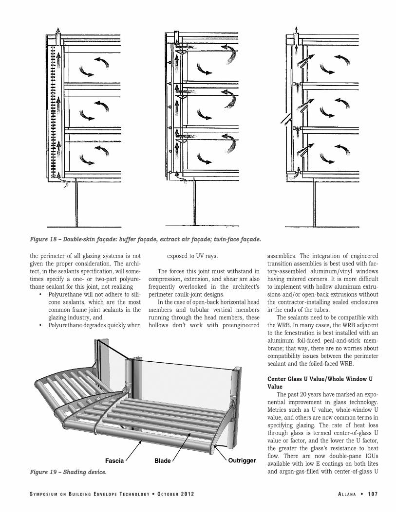
For the exterior wall design• Double-skin façade (DFS) as in
Figure 18• Shading devices (Figure 19)
Critical to the en-ergy performance ofthe curtain wall arethese three attri-butes:
• Continuity of the air barrier• Center glass “U” value/whole-win-
dow “U” value• Solar heat gain coefficient (SHGC)
Continuity of the Air BarrierThe air barrier within the curtain wall
system—from the exterior face of glassacross glazing gaskets/sealants to theframe—and from the frame, across fluid-applied sealant joints to the weather-resis-tive barrier (WRB) in the adjacent construc-tion, must be uninterrupted. Often, thechoice of sealant(s) plus the joint design at
1 0 6 • A L L A N A S Y M P O S I U M O N B U I L D I N G E N V E L O P E T E C H N O L O G Y • O C T O B E R 2 0 1 2
Figure 15 – Poured and debridged polyurethane thermalbreaks detail.
Figure 16 – Glaze-reinforced polyamide thermal breaksdetail.
Figure 17 – Structural silicone glazing (SSG) detail.
the perimeter of all glazing systems is notgiven the proper consideration. The archi-tect, in the sealants specification, will some-times specify a one- or two-part polyure-thane sealant for this joint, not realizing
• Polyurethane will not adhere to sili-cone sealants, which are the mostcommon frame joint sealants in theglazing industry, and
• Polyurethane degrades quickly when
exposed to UV rays.
The forces this joint must withstand incompression, extension, and shear are alsofrequently overlooked in the architect’sperimeter caulk-joint designs.
In the case of open-back horizontal headmembers and tubular vertical membersrunning through the head members, thesehollows don’t work with preengineered
assemblies. The integration of engineeredtransition assemblies is best used with fac-tory-assembled aluminum/vinyl windowshaving mitered corners. It is more difficultto implement with hollow aluminum extru-sions and/or open-back extrusions withoutthe contractor-installing sealed enclosuresin the ends of the tubes.
The sealants need to be compatible withthe WRB. In many cases, the WRB adjacentto the fenestration is best installed with analuminum foil-faced peal-and-stick mem-brane; that way, there are no worries aboutcompatibility issues between the perimetersealant and the foiled-faced WRB.
Center Glass U Value/Whole Window UValue
The past 20 years have marked an expo-nential improvement in glass technology.Metrics such as U value, whole-window Uvalue, and others are now common terms inspecifying glazing. The rate of heat lossthrough glass is termed center-of-glass Uvalue or factor, and the lower the U factor,the greater the glass’s resistance to heatflow. There are now double-pane IGUsavailable with low E coatings on both litesand argon-gas-filled with center-of-glass U
S Y M P O S I U M O N B U I L D I N G E N V E L O P E T E C H N O L O G Y • O C T O B E R 2 0 1 2 A L L A N A • 1 0 7
Figure 19 – Shading device.
Figure 18 – Double-skin façade: buffer façade, extract air façade; twin-face façade.
values as low as 0.20 or R-5. For whole-window “U” value, including glass andframe, the National Fenestration RatingCouncil (NFRC) has developed a procedure,NFRC 100, for determining the fenestrationproduct U value. This whole-window Uvalue is commonly higher than the center-of-glass U value. A high-performance, dou-ble-glazed window can have U values of0.30 or lower. As the description of U valueimplies, low U values are most important inheating-dominated climates, although theyare also beneficial in cooling-dominated cli-mates.
Solar Heat-Gain Coefficient (SHGC)Solar heat gain coefficient (SHGC) is the
fraction of incident solar radiation passingthrough a window, both directly transmittedand absorbed, then released inward. SHGCis expressed as a number between 0 and 1.The lower the SHGC of a window assembly,the less solar heat it transmits. The nation-ally recognized SHGC rating method is theNFRC 200 procedure for determining fenes-tration product solar heat gain coefficientand visible transmittance at normal inci-dence. Whole-window SHGC is lower thanglass only SHGC, and is generally below 0.7.While solar heat gain can provide free heatin winter, it can also lead to overheating insummer. To best balance solar heat gainwith an appropriate SHGC, the designermust consider climate, orientation, shadingconditions, and other factors.
CURTAIN WALL TESTPROCEDURES
Testing can occur at various stages of aproject, including preconstruction mock-upstages and forensic investigations for possi-ble defect analysis. The curtain wall testprocedures outlined in this section are lab-oratory performance testing and not field-testing procedures for installed fenestrationsystems. There is a wide array of testingprocedures available to the designer andinstaller, including the following.
Air Infiltration – ASTM E283Static pressure test to measure air infil-
tration through the specimen by evacuatingair from the test chamber, typically mea-sured at 6.24 psf. for architectural productsand 1.57 psf. for one- to two-story residen-tial. The maximum allowed industry stan-dard for architectural fixed glazing is 0.06cfm at 6.24 psf.
Static Water Infiltration – ASTM E331Static pressure test to determine leak
resistance through the specimen by spray-ing water at a uniform rate of 5 gals./hr./sq. ft., while simultaneously evacuating airfrom the test chamber at the specified watertest pressure (WTP). Typically, the WTP isspecified at 20% of the positive design windload, but not less than 6.24 psf. (defaultpressure for architectural rated systemsand 2.86 psf. for residential systems).Allana Buick & Bers recommends WTP at20% (recommended by AAMA) of positivedesign wind pressure (Pd), but not less than12 psf. (for any curtain wall taller than tenfloors).
Dynamic Water Infiltration – AAMA501.1
Dynamic test using the same rate ofwater delivery in ASTM E331 but using anaircraft engine to provide real-world positivepressure to the specimen’s exterior. WTPdetermined in the same manner as above.
Structural Testing – ASTM E3301. Testing via static air pressure at
both the (+) and (-) Pd while mea-suring frame and glass deflections.Industry standarddeflection limitsa. For spans up to
12.5 ft. = L/175b. For spans >12.5
ft. and up to 40ft. = L/240 + 0.25
c. For glass = 1.0in. (NOTE: Inh i g h - v e l o c i t yhurricane zones[HVHZ]), thislimit does notapply, providedthe glassstrength analysisperformed perASTM E1300proves that theprobability ofbreakage due towind pressuredoes not exceed 8lts/1000 for ver-tical glazing andsloped glazing≤15 degrees fromvertical; forsloped glazing>15 degrees from
vertical, the probability of break-age may not exceed 1 lt/1000.
2. After passing the structural tests atPd, the specimens must pass thetest or proof load that provides thissafety factor:a. For vertical glazing and sloped
glazing ≤15 degrees from verti-cal, Pd is multiplied by 1.5.
b. For sloped glazing >15 degrees,Pd is multiplied by 2.0.
c. Deflections are not recorded,and the specimens pass whenthere is no glass breakage andthe permanent set (deformation)is ≤0.2% of span for architectur-al products and ≤0.4% for resi-dential products.
d. Sloped glazing in areas subjectto snow accumulation musthave the wind pressure Pd in-creased by a factor representingexpected snow load.
e. Seismic or Wind-induced Inter-story Drift – AAMA 501.4 – Statictest method focuses primarily onchanges in serviceability of thespecimen after horizontal rack-ing at the design displacement
1 0 8 • A L L A N A S Y M P O S I U M O N B U I L D I N G E N V E L O P E T E C H N O L O G Y • O C T O B E R 2 0 1 2
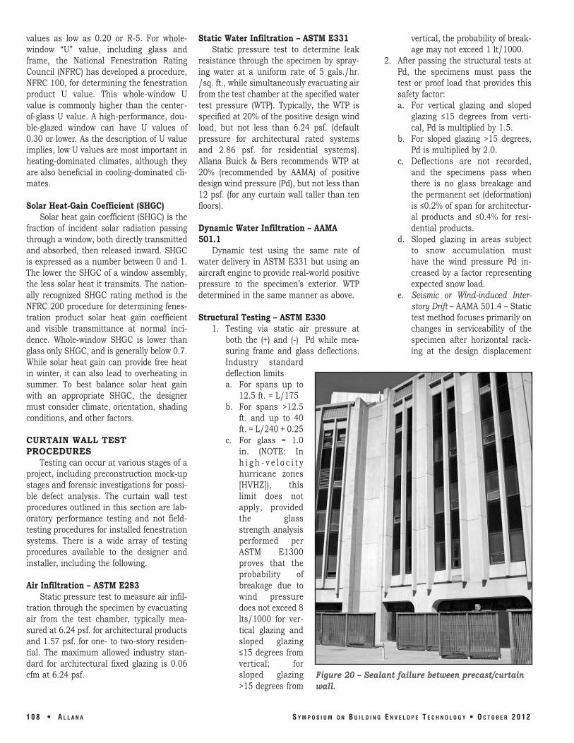
Figure 20 – Sealant failure between precast/curtainwall.

(Dp), after which thespecimen is subjected torepeat air and watertests. Then, after the“proof” test at 1.5 Pd,501.4 is repeated at 1.5Dp. Pass/fail criteria aredependent upon thebuilding’s use and occu-pancy.
Other Tests1. AAMA 501.5 – Thermal
Cycling2. AAMA 501.6 – Seismic Drift
Causing Glass Fallout3. AAMA 501.7 – Vertical
Seismic Displacement4. ASTM E1886 and E1996 –
Large and Small MissileImpact and Cycling
5. Blast resistance6. Window-washing tie-back
load test
FORENSIC CASE STUDIESSealant Failures
The linear coefficient of thermal expansion of aluminum is dou-ble that of concrete. Narrow vertical aluminum-strip windows wereinstalled four floors high between precast concrete panels (see Figure20). The sealant at the window jambs failed and caused water infil-tration.
The sealant joint at the window jambs was not designed wideenough to accommodate the resulting shear forces from differentialthermal movement (see Figure 21). These joints were even too nar-row to preclude replacing the existing sealant with one having twicethe extension capacity of the original.
Perimeter sealant failure was proven and documented via test-ing. This failure was addressed by this remedial process.
The most cost-effective remedy to this leaking problem was to
S Y M P O S I U M O N B U I L D I N G E N V E L O P E T E C H N O L O G Y • O C T O B E R 2 0 1 2 A L L A N A • 1 0 9
Figure 21 – Sealant joint width too narrowto handle shear in sealant.
Figure 23 – Segmented window wall.
Figure 22 – Precured sealantcan handle 200% extension.
Typicalaluminumspandreland vents
overlay the failed sealant with precured sili-cone with at least four times the extensioncapacity of the original sealant (see Figure22). One half inch of each edge of the pre-cured silicone was adhered to the alu-minum and concrete with silicone sealant.
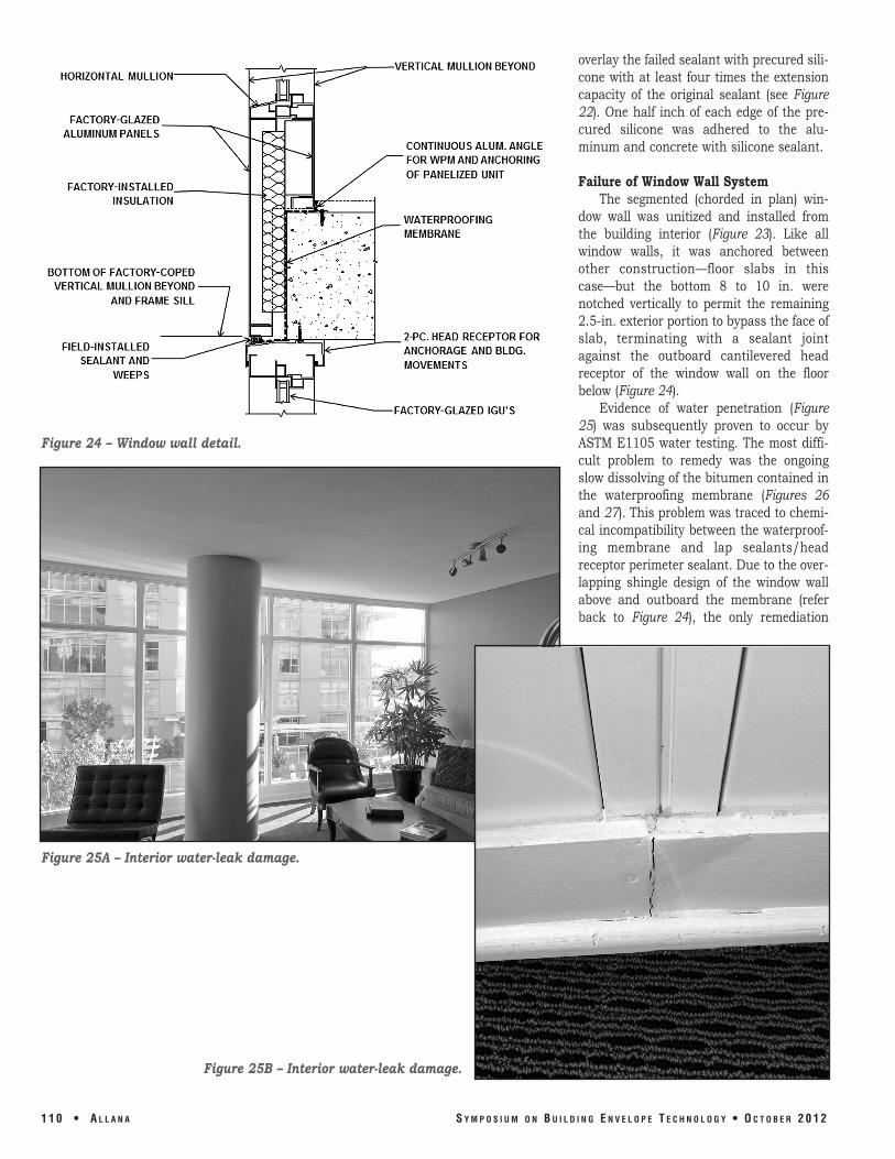
Failure of Window Wall SystemThe segmented (chorded in plan) win-
dow wall was unitized and installed fromthe building interior (Figure 23). Like allwindow walls, it was anchored betweenother construction—floor slabs in thiscase—but the bottom 8 to 10 in. werenotched vertically to permit the remaining2.5-in. exterior portion to bypass the face ofslab, terminating with a sealant jointagainst the outboard cantilevered headreceptor of the window wall on the floorbelow (Figure 24).
Evidence of water penetration (Figure25) was subsequently proven to occur byASTM E1105 water testing. The most diffi-cult problem to remedy was the ongoingslow dissolving of the bitumen contained inthe waterproofing membrane (Figures 26and 27). This problem was traced to chemi-cal incompatibility between the waterproof-ing membrane and lap sealants/headreceptor perimeter sealant. Due to the over-lapping shingle design of the window wallabove and outboard the membrane (referback to Figure 24), the only remediation
1 1 0 • A L L A N A S Y M P O S I U M O N B U I L D I N G E N V E L O P E T E C H N O L O G Y • O C T O B E R 2 0 1 2
Figure 24 – Window wall detail.
Figure 25A – Interior water-leak damage.
Figure 25B – Interior water-leak damage.

possible is to demolish and replace theentire window wall and membrane.
CONCLUSIONThe modern curtain wall, having
reached a high level of sophistication with-in the past five decades, continues to evolvein response to architectural design coupledwith energy conservation and energy pro-duction.
The recent exponential improvements inglass technology, combined with more energy-efficient framing systems, bode well forowners and designers who strive to improvethe built environment through reductionsin carbon emissions, maximizing daylight-ing without increasing energy consumption,reducing glare, and increasing thermalcomfort.
However, as curtain wall constructionhas evolved, new considerations and issueshave arisen as evidenced by the case stud-ies. As we continue this evolution to meetnew, more demanding performance re-quirements, it can be anticipated that moreconsiderations and challenges will arise.
S Y M P O S I U M O N B U I L D I N G E N V E L O P E T E C H N O L O G Y • O C T O B E R 2 0 1 2 A L L A N A • 1 1 1
Figure 26 – Bitumen membranemelting.
Figure 27 – Interior stainsfrom melting bitumen.
Typicalthrough-wall vent
Bitumenmelting of the
southsegmentedwindow wall
system