cursor 13 mar gb - powertech engines inc -- authorized ...€¦ · cursor 13 series c13 ens m33 c13...
TRANSCRIPT

copertina cursor 13 series 26-10-2006 10:58 Pagina 1
Colori compositi
C M Y CM MY CY CMY K
USE AND MAINTENANCEUSO E MANUTENZIONEUTILISATION ET ENTRETIENBETRIEB UND WARTUNGUSO Y MANTENIMIENTO
CURSOR 13 SERIES
Publication edited byMarketing - Adv. & PromotionPrint L31900013 - 10/06
MARINE ENGINES

1
EN
GL
ISH
CURSOR 13 SERIES
C13 ENS M33C13 ENT M50C13 ENT M77
USE AND MAINTENANCE
FOREWORDThank you for choosing IVECO MOTORS and congratulations foryour choice of engine.Before carrying out any operation involving the engine and itsequipment, please read carefully the instructions contained in thismanual. Compliance with them is the best way to guarantee a perfectand durable operation of your engine.
The contents of this manual only refer to the standard configurationof the engine and the pictures are given only as an indication. Someinstructions provided describe the sequence to be applied in order toobtain engine's and relevant equipment's expected performance. Insome cases they depend upon the configuration of controls and fittingsof the boat on which the engine is installed. Although they may differfrom the contents of this manual, please refer to yard instructions orto a specific manual thereof.The information contained herein are updated as of the date of theirpublishing.The Manufacturer reserves the right of applying changes withoutnotice and at any time, for technical or commercial reasons and inorder to make engines compliant with the law requirements of thedifferent countries.The Manufacturer waives any liability for any errors or omissions.
The IVECO MOTORS Customer Service Network competence andprofessionalism of the Customer Service Network is always availablewherever you are.

2
TABLE OF CONTENTS Page
GENERAL . . . . . . . . . . . . . . . . . . . . . . . . . . . . . . . . . . . . . . . . . . . . . .3Guarantee . . . . . . . . . . . . . . . . . . . . . . . . . . . . . . . . . . . . . . . . . . . . . .3Spare parts. . . . . . . . . . . . . . . . . . . . . . . . . . . . . . . . . . . . . . . . . . . . . .3Liabilities. . . . . . . . . . . . . . . . . . . . . . . . . . . . . . . . . . . . . . . . . . . . . . . .3Safety . . . . . . . . . . . . . . . . . . . . . . . . . . . . . . . . . . . . . . . . . . . . . . . . . .3C13 ENS M33 engines technical data . . . . . . . . . . . . . . . . . . . . . . .4C13 ENT M50 engines technical data . . . . . . . . . . . . . . . . . . . . . . .6C13 ENT M77 engines technical data . . . . . . . . . . . . . . . . . . . . . . .8Labels . . . . . . . . . . . . . . . . . . . . . . . . . . . . . . . . . . . . . . . . . . . . . . . . .10USE . . . . . . . . . . . . . . . . . . . . . . . . . . . . . . . . . . . . . . . . . . . . . . . . . . .11Preliminary testing. . . . . . . . . . . . . . . . . . . . . . . . . . . . . . . . . . . . . . .11Starting and stopping the engine . . . . . . . . . . . . . . . . . . . . . . . . . . .11Starting and stopping the engine from an analog instrument panel .. . . . . . . . . . . . . . . . . . . . . . . . . . . . . . . .12Recognizing alarm statuses . . . . . . . . . . . . . . . . . . . . . . . . . . . . . . .15Starting and stopping the engine from digital instrument panel . . . . . . . . . . . . . . . . . . . . . . . . . . . . . . . . . .16Recognizing alarm statuses . . . . . . . . . . . . . . . . . . . . . . . . . . . . . . .18Safety and monitoring system . . . . . . . . . . . . . . . . . . . . . . . . . . . . .21Engine management from C13 ENT M50 relay box . . . . . . . . . .29Engine management from C13 ENT M77 relay box . . . . . . . . . .30For a correct use of the engine. . . . . . . . . . . . . . . . . . . . . . . . . . . .31Special warnings . . . . . . . . . . . . . . . . . . . . . . . . . . . . . . . . . . . . . . . .32Running-in . . . . . . . . . . . . . . . . . . . . . . . . . . . . . . . . . . . . . . . . . . . . .33Refuelling . . . . . . . . . . . . . . . . . . . . . . . . . . . . . . . . . . . . . . . . . . . . . .34INSPECTIONS AND MAINTENANCE . . . . . . . . . . . . . . . . . . .35Maintenance staff . . . . . . . . . . . . . . . . . . . . . . . . . . . . . . . . . . . . . . .35Accident prevention . . . . . . . . . . . . . . . . . . . . . . . . . . . . . . . . . . . . .35Frequency . . . . . . . . . . . . . . . . . . . . . . . . . . . . . . . . . . . . . . . . . . . . .36Prescriptions . . . . . . . . . . . . . . . . . . . . . . . . . . . . . . . . . . . . . . . . . . .38How to. . . . . . . . . . . . . . . . . . . . . . . . . . . . . . . . . . . . . . . . . . . . . . . .38Moving The Engine . . . . . . . . . . . . . . . . . . . . . . . . . . . . . . . . . . . . . .49Exhaust parts dismissal . . . . . . . . . . . . . . . . . . . . . . . . . . . . . . . . . . .49LONG ENGINE INACTIVITY . . . . . . . . . . . . . . . . . . . . . . . . . . .50
Page
Engine Preparation For Long Inactivity Periods . . . . . . . . . . . . . . .50Commissioning After An Extended Period Of Inactivity . . . . . . .50Instructions for first startup or after an extended period of inactivity . . . . . . . . . . . . . . . . . . . . . . . . . . . . . . . 51ENGINE FAILURES. . . . . . . . . . . . . . . . . . . . . . . . . . . . . . . . . . . . . . 52EMERGENCY ON BOARD . . . . . . . . . . . . . . . . . . . . . . . . . . . . . . 53APPENDIX . . . . . . . . . . . . . . . . . . . . . . . . . . . . . . . . . . . . . . . . . . . . . . . .Oil viscosity compared to ambient temperatures.On board panels requirements.

3
EN
GL
ISH
GENERAL
GUARANTEEIn order to obtain the engine best performance and to make use ofIVECO MOTORS guarantee it is necessary to strictly observe theinstruction contained in this manual. Failure to do so may cause theguarantee to become invalid.
SPARE PARTSIn order to maintain the original integrity of the engine, it is essential touse only IVECO MOTORS genuine spare parts.Using non genuine spare parts may cause the guarantee to decay andwaives any IVECO MOTORS liability for the entire life of the engine.
LIABILITIESThe Manufacturer's liability is subject to the execution of the controland maintenance interventions contained and described in this manual,the performance of which shall be duly proven. Should anyextraordinary maintenance intervention be required, it shall be carriedout by qualified staff at IVECO MOTORS authorized shop, using thespecific instruments and equipment.
SAFETYThe following information is provided in order to bring the attentionto the use of the engine in order to prevent any damage to people andproperties arising out of misconduct.
Engines should be used exclusively for the applications stated bythe manufacturer.
Any tampering, modifications, or use of non-original par ts mayjeopardize the safety of service personnel and boat users;absolutely avoid any change to cables or units of the engine orto connect it to foreign electric networks.
Pay attention to the moving parts of the engine, to those with hightemperature and to the circuits with pressurized fluids, as theelectric equipment is subject to voltage and electric currents.
Engine exhaust gases can be dangerous for health.
Engine displacement should take place with suitable lifting means,using the special eyelets provided.
Do not commission the engine before having met the safetyrequirements provided for the boat on which is has been installedand observe local rules and regulations.
Any required intervention in order to improve use andconservation of the engine should be carried out exclusively byIVECO MOTORS approved staff.
See INSPECTIONS AND MAINTENANCE for further safetyreccomandations.

4
C13 ENS M33 ENGINE TECHNICAL DATAThe technical acronym and the serial number are specified on thenameplate which - based on the model - can be found on differentparts of the engine: flywheel casing, tappet cover, coolant pan.
(*)Flywheel net power compliant with ISO 3046-1 standard. Testingconditions: T 25°C; atmospheric pressure 100 kPa; relativehumidity 30%.
Acronym C13 ENS M33
Engine family F3B
Cycle 4-Stroke Diesel
Number and arrangementof cylinders 6, in line
Stroke boring 135 x 150 mm
Total diplacement 12,800 cm3
Air supply Boosted (TC)
Injection method Direct EUI with electronic management
Engine rotation direction Counterclockwise (from flywheel side)
Weight without liquids 2,965.22 lb
Electrical system 24 V
Battery/iescapacitybreakaway current
120 Ah or higher900 A or higher
Available ratings (*) C13 ENS M33
D 243 kW (330 CV) @ 1800 rpm
WARNING
It is strictly forbidden to alterate the above mentioned features andmore specifically to change the information stored in the electronicunits of the injection system or the engine and relevant fitting features.Any non observance of the above shall null any warranty and IVECOMOTORS liability.
5
EN
GL
ISH
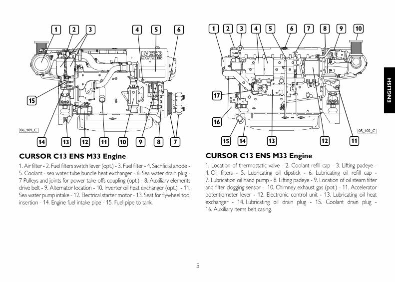
CURSOR C13 ENS M33 Engine1. Air filter - 2. Fuel filters switch lever (opt.) - 3. Fuel filter - 4. Sacrificial anode -5. Coolant - sea water tube bundle heat exchanger - 6. Sea water drain plug -7 Pulleys and joints for power take-offs coupling (opt.) - 8. Auxiliary elementsdrive belt - 9. Alternator location - 10. Inverter oil heat exchanger (opt.) - 11.Sea water pump intake - 12. Electrical starter motor - 13. Seat for flywheel toolinsertion - 14. Engine fuel intake pipe - 15. Fuel pipe to tank.
CURSOR C13 ENS M33 Engine1. Location of thermostatic valve - 2. Coolant refill cap - 3. Lifting padeye -4. Oil filters - 5. Lubricating oil dipstick - 6. Lubricating oil refill cap -7. Lubrication oil hand pump - 8. Lifting padeye - 9. Location of oil steam filterand filter clogging sensor - 10. Chimney exhaust gas (pot.) - 11. Acceleratorpotentiometer lever - 12. Electronic control unit - 13. Lubricating oil heatexchanger - 14. Lubricating oil drain plug - 15. Coolant drain plug -16. Auxiliary items belt casing.
06_101_C 05_102_C

6
C13 ENS M50 ENGINE TECHNICAL DATAThe technical acronym and the serial number are specified on thenameplate which - based on the model - can be found on differentparts of the engine: flywheel casing, tappet cover, coolant pan.
(*)Flywheel net power compliant with ISO 3046-1 standard. Testingconditions: T 25°C; atmospheric pressure 100 kPa; relativehumidity 30%.
Sigla C13 ENT M50
Engine family F3B
Cycle 4-Stroke Diesel
Number and arrangementof cylinders 6, in line
Stroke boring 135 x 150 mm
Total diplacement 12,800 cm3
Air supply Boosted and Aftercooled(TCA or TAA)
Injection method Direct EUI with electronic management
Engine rotation direction Counterclockwise (from flywheel side)
Weight without liquids 2,965.22 lb
Electrical system 24 V
Battery/iescapacitybreakaway current
120 Ah or higher900 A or higher
Available ratings (*) C13 ENT M50
C 382 kW (520 CV) @ 2000 rpm
D 368 kW (500 CV) @ 2000 rpm
WARNING
It is strictly forbidden to alterate the above mentioned features andmore specifically to change the information stored in the electronicunits of the injection system or the engine and relevant fitting features.Any non observance of the above shall null any warranty and IVECOMOTORS liability.

7
EN
GL
ISH
Motore CURSOR C13 ENT M501. Air filter - 1. Fuel filters switch lever (opt.) - 3. Fuel filter - 4. Air-sea waterheat exchanger - 5. Sacrificial anode - 6. Sacrificial anode - 7. Coolant - seawater tube bundle heat exchanger - 8. Sea water drain plug - 9 Pulleys andjoints for power take-offs coupling (opt.) - 10. Auxiliary elements drive belt -11. Alternator location - 12. Inverter oil heat exchanger (opt.) - 13. Sea waterpump intake - 14. Electrical starter motor - 15. Seat for flywheel toolinsertion - 16. Engine fuel intake pipe - 17. Fuel pipe to tank.
Motore CURSOR C13 ENT M501. Location of thermostatic valve - 2. Coolant refill cap - 3. Liftingpadeye - 4. Oil filters - 5. Lubricating oil dipstick - 6. Lubricating oil refillcap - 7. Lubrication oil hand pump - 8. Lifting padeye - 9. Location ofoil steam filter and filter clogging sensor - 10. Chimney exhaust gas (pot.) -11. Accelerator potentiometer lever - 12. Central electronic unit -13. Lubricating oil heat exchanger - 14. Lubricating oil drain plug - 15. Seawater spillage drainage duct - 16. Auxiliary items belt casing - 17. Coolant drainplug.
05_101_C
05_102_C

8
C13 ENT M77 ENGINE TECHNICAL DATAThe technical acronym and the serial number are specified on thenameplate which - based on the model - can be found on differentparts of the engine: flywheel casing, tappet cover, coolant pan.
(*)Flywheel net power compliant with ISO 3046-1 standard. Testingconditions: T 25 °C; atmospheric pressure 100 kPa; relativehumidity 30%.
Acronym C13 ENT M77
Engine family F3B
Cycle 4-Stroke Diesel
Number and arrangementof cylinders 6, in line
Stroke boring 135 x 150 mm
Total displacement 12,800 cm3
Air supply Boosted and Aftercooled(TCA or TAA)
Injection method Direct EUI with electronic management
Engine rotation direction Counterclockwise (from flywheel side)
Weight without liquids 3,042.33 lb
Electrical system 24 V
Battery/iescapacitybreakaway current
120 Ah or higher900 A or higher
Available ratings (*) C13 ENT M77
A1 567 kW (770 CV) @ 2300 rpm
A2 515 kW (700 CV) @ 2300 rpm
B 442 kW (600 CV) @ 2300 rpm
C 397 kW (540 CV) @ 2300 rpm
WARNING
It is strictly forbidden to modify the above mentioned features andmore specifically to change the information stored in the electronicunits of the injection system or the features of the engine and relevantfittings. Any non observance of the above shall null any warranty andIVECO MOTORS liability.

9
EN
GL
ISH
CURSOR C13 ENT M77 Engine1. Air filter - 1. Fuel filters switch lever (opt.) - 3. Fuel filter - 4. Air-sea waterheat exchanger - 5. Sacrificial anode - 6. Sacrificial anode - 7. Coolant - seawater tube bundle heat exchanger - 8. Sea water drain plug - 9 Pulleys andjoints for power take-offs coupling (opt.) - 10. Auxiliary elements drive belt -11. Alternator location - 12. Inverter oil heat exchanger (opt.) - 13. Sea waterpump intake - 14. Electrical starter motor - 15. Seat for flywheel toolinsertion - 16. Engine fuel intake pipe - 17. Fuel pipe to tank.
CURSOR C13 ENT M77 Engine1. Location of thermostatic valve - 2. Coolant refill cap - 3. Liftingpadeye - 4. Oil filters - 5. Lubricating oil dipstick - 6. Lubricating oil refillcap - 7. Lubrication oil hand pump - 8. Lifting padeye - 9. Location ofoil steam filter and filter clogging sensor - 10. Chimney exhaust gas (pot.) -11. Accelerator potentiometer lever - 12. Air filter - 13. Lubricating oil heatexchanger - 14. Lubricating oil drain plug - 15. Sea water spillage drainageduct - 16. Auxiliary items belt casing - 17. Coolant drain plug.
05_103_C 05_104_C

10
LABELSBelow you can find the explanation of the caution labels located onthe engine.NOTE: Labels with an exclamative point highlight a potentialdanger.
Lifting point (engine only).
Fuel refill plug(on tank, if available).
Lubricant refill plug.
Lubricating oil dipstick.
Burn hazard: Pressurised hot water expulsion.
Burn hazard: High temperature parts.
Fire hazard: Fuel presence.
Hazard of collision and contactwith moving parts: Presence of fans, pulleys, belts or other.

11
EN
GL
ISH
USE
PRELIMINARY TESTINGBefore each engine startup:
Make sure that the sea water intake valve is open. Dry operation ofthe pump would cause in few seconds irreparable damages to theinternal rotor.
Check technical fluids level (fuel, engine oil and coolant).
STARTING AND STOPPING THE ENGINE
For boats equipped with instrument panel notmanufactured by IVECO MOTORSStart-up and shut-down modes described on the following pages areapplicable if an IVECO MOTORS instrument panel is installed onboard. Should the boat be equipped with a customized dashboardwhich has been manufactured at the Yard or by the Boat builder, suchprocedures may change based on the panel's specific features. In suchcases please observe the Yard's startup/stop sequences and read theindication instruments as specified in the relevant documentation.
Engines equipped with pre-lubrication electricsystemThe pre-lubrication feature is started by acting on the power switch ofthe electrical system and the relevant warning light lits up.The engine startup sequence described in the following pages shalltake place after the required pre-lubrication time has elapsed and thewarning light is turned off or only after the warning light has gone out.
- Electronic pre-lubrication and transfer unit -
Pre-lubrication of engine parts can also be carried out in manual mode.If necessary, proceed as follows: 1. Ensure that the ignition key switch is turned off (STOP).2. Check that switch B on the pre-lubrication electronic unit is in “EV OFF” position, then press the adjacent pushbutton A towards “DISCHARGE”. 3. Keep the pushbutton pressed long enough to allow complete pre- lubrication. 4. Start the engine as described on the following pages.
WARNING!
Before starting up the engine make sure no comburentvapour or gas is in the engine room.
04_037_C
A B

12
ENGINE START-UP AND SHUT-DOWN FROM IVECO MOTORS ANALOGUE INSTRUMENT PANEL
Start-up procedure from main panelMake sure that the electric switch with ENGINE ROOM - BRIDGElabel on the Relay box unit, (usually located in the engine room) isturned to BRIDGE, then proceed as follows:
1. Lift the key switch safety cover (8), insert the key and turn it to theright, to 8B position.
2. Check that the analog instruments provide acceptable reading withthe values of the relevant physical parameters (temperature,battery voltage and oil pressure).
3. Wait for the acoustic alarm to stop and that the alarm warnings (5)on the signaling module are switched off (except for "alternatoranomaly" and "oil low pressure"). At the same time check thattesting of indicators is successful (see relevant section as regardstest reading and module indication instructions).
4. Turn the key to 8C position and realeas it without acceleratingwhen the engine has started.
5. Check that the analog instruments provide acceptable reading withthe new values of the relevant physical parameters (temperature,battery voltage and oil pressure).
6. In case startup fails, you can resume startup position only afterreleasing the key and after turning the switch 8A to the stopposition.
1. Coolant temperature indicator - 2. Tachometer and hour counter -3. Voltmeter - 4. Horn - 5. Alarms and signaling module 6. Engine oilpressure indicator - 7. Panel instruments light switch - 8. Key switch forengine startup/stop - 9. Engine stop push button - 10. Horn silencingpush button.
1
2
3
45
67
89
10
04_354_N
8A 8B
8C04_356_N
Switch key detail
13
EN
GL
ISH
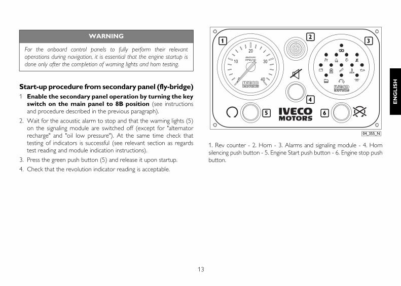
Start-up procedure from secondary panel (fly-bridge)1 Enable the secondary panel operation by turning the key
switch on the main panel to 8B position (see instructionsand procedure described in the previous paragraph).
2. Wait for the acoustic alarm to stop and that the warning lights (5)on the signaling module are switched off (except for "alternatorrecharge" and "oil low pressure"). At the same time check thattesting of indicators is successful (see relevant section as regardstest reading and module indication instructions).
3. Press the green push button (5) and release it upon startup.
4. Check that the revolution indicator reading is acceptable.
1. Rev counter - 2. Horn - 3. Alarms and signaling module - 4. Hornsilencing push button - 5. Engine Start push button - 6. Engine stop pushbutton.
WARNING
For the onboard control panels to fully perform their relevantoperations during navigation, it is essential that the engine startup isdone only after the completion of warning lights and horn testing.
5
1 32
6
4
04_355_N

14
Engine stopBefore stopping the engine it is recommended to keep it running atidle and unloaded for few minutes; this will allow for a uniformreduction of temperature and avoid harmful thermal shocks.
A. To stop the engine from IVECO MOTORS main panel, turn thekey switch to the stop position 8A or act on any similar control ifyour boat is equipped with a customized dashboard.
B. To stop the IVECO MOTORS secondary panel press the red pushbutton (6) located on it.
To stop the IVECO MOTORS main panel for the engines equippedwith "in eccitazione" device (available upon request or prescribed bycertification authorities), press the red push button(9).
To restart the engine from the main panel:
1. Turn the key switch to the stop position 8A to reset any paneloperation enabled.
2. Proceed as shown.
To restart the engine from the secondary panel:
1. Make sure the panel is enabled (key switch on the main panelturned to 8B).
2. Press the green push button (5) and release it when it has started,making sure that the revolution indicator reading is acceptable.

15
EN
GL
ISH
RECOGNIZING ALARM STATUSESIVECO MOTORS onboard panels equipped with analog instrumentsinclude an electronic module with indicator lights and interface circuits,timing and saving of alarms.The figure shows the module quadrant and the legend contains themeaning of the alarm pictorial corresponding to each light indicator; insome engine type and relevant fitting are not equipped with all of thefeatures mentioned herein.Moreover these instructions may change based on the technicalfeatures provided by the boat manufacturer.
OperationBy rotating the key switch to 8B position the alarms and signalingmodule performs a 5 seconds efficiency test of all light indicators,except for those concerning “Pre-lubrication”, “Pre-post heating”,“EDC system fault”, and the horn beeps.The beep may be silenced before the end of the test, by pushing therelevant button.During the startup phase and for the next 15 seconds, any alarmfunction is inhibited; after such time interval each alarm conditiondetected by sensors on the engine causes the relevant indicator toblink and a simultaneous sound signal. The horn silencing obtained bypressing the relevant push button causes the non-blinking indicator toturn on and saves the alarm until the next engine stop.
1. Maximum allowed speed (on request) - 2. Water in the fuel pre-filter- *3. Engine coolant low level - 4. Alternator anomaly - *5. Oilfilter clogging - *6. Oil vapors filter clogging - *7. Pre-lubricationrunning - 8. Air filter clogging - *9. Fuel filter clogging - 10. Coolant hightemperature - 11. Oil low pressure - *12. Pre-post heating - 13. EDCinjection system fault.
*Alarm features not available with standard fitting.
12 12
11101334
5 6 8 9
7
04_234_N

16
ENGINE START-UP AND SHUT-DOWN FROM IVECO MOTORS DIGITAL INSTRUMENT PANEL(Not applicable to C13 ENT M77 engine )
Startup procedure from main panel Make sure that the electric switch with ENGINE ROOM - BRIDGE labelon the Relay box unit, (usually located in the engine room) is turned toBRIDGE, then proceed as follows:
1. Lift the key switch safety cover (8), insert the key and turn it to theright, to 8B position.
2. Check that the analog instruments provide acceptable reading withthe new values of the relevant physical parameters.
3. Wait for the acoustic alarm to stop and that the warning lights (5)on the signaling module are switched off (except for "alternatoranomaly" and "oil low pressure"). At the same time check thattesting of indicators is successful (see relevant sectionRECOGNIZING ALARM STATUSES).
4. Turn the key to 8C position and release it without acceleratingwhen the engine has started.
5. Check that the analog instruments provide acceptable reading withthe new values of the relevant physical parameters (temperature,battery voltage and oil pressure).
6. In case startup fails, you can resume startup position only afterreleasing the key and after turning the switch 8A to stop position.
1. Engine coolant temperature indicator - 2. Lubrication circuitpressure indication - 3. Service and alarm signals - 4. Revolutioncounter - 5. Air booster pressure indicator - 6. Voltmeter -7. Alphanumeric display - 8. Engine start/stop key switch - 9. Accessoryfunctions programming key - 10. Additional information slide selectionkey - 11. “Programmed maintenance” reset key - 12. Horn silencer -13. Horn.
1
2
4
6
5
89111213
3 3
10
7
04_357_N
8A 8B
8C04_356_N
Switch key detail

17
EN
GL
ISH
Startup procedure from secondary panel or fly-bridge1. Enable the secondary panel operation by turning the key switch on
the main panel to 8B position (see instructions described in theprevious paragraph).
2. Wait for the acoustic alarm to stop and that the warning lights (5)on the signaling module are switched off (except for "alternatoranomaly" and "oil low pressure"). At the same time check thattesting of indicators is successful (see relevant sectionRECOGNIZING ALARM STATUSES).
3. Press the green START (11) push button and release it when theengine has started. Check that instruments and analogic reading areacceptable.
1. Engine coolant temperature indicator - 2. Lubrication circuitpressure indication - 3. Service and alarm signals- 4. Revolutioncounter - 5. Air booster pressure indicator - 6. Voltmeter -7. Alphanumeric display - 8. Engine stop button - 9. Additional
information slide selection key - 10. Horn silencer - 11. Engine startbutton.
1
2
6
5
3 3
4
7
1011 9 8
04_358_N

18
Engine stopBefore stopping the engine it is recommended to keep it running atidle and unloaded for few minutes; this will allow for a uniformreduction of temperature and avoid harmful thermal shocks.
A. From the main panel: rotate the key switch to the stop 8Aposition.
B. From the secondary panel: press the red STOP push button(8) located on it.
To restart the engine from the main panel:
1. Turn the key switch to the stop position 8A to reset any paneloperation enabled.
2. Proceed as shown in the relevant paragraph.
To restart the engine from the secondary panel:
1. Make sure the panel is enabled (key switch on the main panelturned to 8B).
2. Press the green START (11) push button and release it when theengine has started. Check that instruments and analogic reading areacceptable.
RECOGNIZING ALARM STATUSESThe following the legend contains the meaning of the alarm pictorialcorresponding to each light indicator on the main and secondary panel;in some engine type and relevant fitting are not equipped with all of thefeatures mentioned herein. Moreover these instructions may changebased on the technical features provided by the boat manufacturer.
* Alarm features not available with standard fitting.
* Clogging oil vapor filter
Alternator anomaly
Low oil pressure
High temperature ofcoolant
Overrun
*Low levelofcoolant
EDC engine control system failure
* Clogging air filter
Maintenance interval expiry
* Clogging oil filter
* Pre-lubrication running
* Pre-post heating
* Clogging fuel filter
Waterin the fuel filter
04_359_N

19
EN
GL
ISH
OperationBy rotating the key switch to 8B position the module performs a 5seconds efficiency test of all light indicators, except for thoseconcerning “Pre-lubrication”, “Pre-post heating”, “EDC system fault”,and the horn beeps. The beep may be silenced before the end of thetest, by pushing the relevant button.During the startup phase and for the next 15 seconds, any alarmfunction is inhibited; after such time interval each alarm conditiondetected by sensors on the engine causes the relevant indicator toblink and a simultaneous sound signal. The sound alarm silencingobtained by pressing the relevant push button causes the non-blinkingindicator to turn on and saves the alarm until the next engine stop.
Alfanumeric displayThe information provided by this indicator are:
• engine revolution speed
• total hours of operation (see note A)
• exhaust gases temperature (upon request)
• instant fuel consumption (see note B)
To select the requested information, press the "Slide selection" pushbutton available on the main and secondary panel.
Detail of the main panel
7. Alphanumeric display - 9. Accessory functions programming button -10. Accessory information slide selector - 11. Pushbutton to turn off“Service due” indicator - 12. Horn silencer.
(A)The electronics inside the panel is programmed in order tocombine the hours of operation to the release of the warning whenthe ordinary maintenance hours limit has been reached. Thisfeature requires that after each maintenance intervention, thecount is reset from the main panel as follows:
- Press and hold the "Prog" (9) and "Slide selection" (10) buttons,turn the key switch from 8A position to 8B and wait for the displayto show the previous data set (ex.: 600 hours). Release the buttonsand press only once the "Prog" button (9) to restart the new count.
9
7
12 11 10
04_360_N

20
In case the information set does not correspond to what provided forthe type of oil used (see REFUELLING and FREQUENCY), proceedas follows:
- After having displayed the hour information previously set, releasethe push buttons and repeatedly press only the "Slide selection"(10) button until the required information blinks (as detailed inFREQUENCY section), then press "Prog" (9) to confirm theinformation and start a new count.
(B)The information regarding the immediate fuel consumption requirethe correct programming of the maximum information enteredrelating to the engine performances. To check proceed as follows:
- Press and hold the "Prog" key (9) until the display reads themaximum value entered (ex.: 195 mg/trk), then release it andcompare the information with those provided in the tale below.
- In case it does not correspond, you can change it by repeatedlypressing the "Slide selection" (10) button until the required one itdisplayed (blinking mode).
- Press and hold the “Prog” (9) button until the engine revolutionspeed is displayed, meaning that the information has been saved.
In case of any mistake in the programming procedure, the displayreading will be "Pr. Err.". You will need to repeat the procedure.
C13 ENS M33
C13 ENT M50
C13 ENT M77
Maximum power(CV) Maximum insertion (mg/strk)
330
Maximum power(CV) Maximum insertion (mg/strk)
520 299
500 299
Maximum power(CV) Maximum insertion (mg/strk)
770
700
600
540

21
EN
GL
ISH
SAFETY AND MONITORING SYSTEMIn compliance with certification authority regulations, some vehiclesare equipped with a security system made up of specific sensorslocated on the engine and of a synoptic panel. The system monitorsengine operating parameters. Together with the monitoring function,system electronics sound an alarm when the thresholds considered tobe safe limits are exceeded and bring about emergency engine shut-down in the event of possible danger to those on board.System unit use and interpretation procedures refer to the equipmentin the standard IVECO MOTORS configuration. Informationassociated with functions that require connection to externalequipment, such as echosounding devices and GPS, is intentionallydisplayed in brief. Programming procedures that are the responsibilityof the Supplier or Assistance Service technicians are not shown. Referto the equipment Supplier’s manuals for information not given in thepresent document.
MonitoringThe display unit allows constant checking of engine parameters asrequired by type approval regulations for rapid detection of arisingfaults. Information contained in the unit memory permits events to beanalysed for a long period preceding an enquiry. Alarms triggered byexceeding the thresholds treated as the limit value of each parameterare signalled by a warning sound and the frame surrounding the boxcontaining information on the faulty parameter flashes.
1. Bar or round analogue gauges referring to the parameter, value andunit of measurement - 2. Recognition of pre-set alarm thresholds -3. Page number - 4. Membrane keys - 5. Warning lights - 6. Keyfunctions.
Information on pages displayed may vary according to the number andtype of engine installed.Key function varies according to the different displays.
05_035_C
1
36
2
5 4

22
Press the “<<” and “>>” keys to display in sequence the pagescontaining monitoring parameter information, including serviceintervals and optional information such as that shown below. The standard IVECO MOTORS configuration will identify thefollowing information:
Engine coolant pressure
(FRSHWATER PRESS)
Low engine coolant level
(LOW WATER LEVEL)
Low engine coolant pressure
(FRESHWATER LOW P)
High engine coolant temperature
Engine oil pressure
Absence of engine oil pressure
(LOW OIL PRESS)
Engine oil temperature (OIL TEMP)
Oil filter clog (OIL FILTER CLOG)
Presence of water in fuel (WATER IN FUEL)
Fuel pressure
Fuel filter clog (FUEL FILTER CLOG)
Injection system damage
Failed battery recharging (BATTERY WARNING)
Pre-lubrication in progress (PRELUBRICATING)*
System power supply voltage (VOLTMETER)
Exhaust gas temperature (EX GAS TEMP)
Engine revolution speed, from EDC system (ENGINE E)
Engine stop circuit fault (MAN STOP L FAULT)
Engine revolution speed, from sensor (ENGINE S)
Engine revolution speed sensor fault
(PICK-UP L FAULT)
Automatic engine stop circuit fault (AUTOSTOP L FAULT)
Air filter clog (AIR FILTER CLOG)
Reversing gear oil pressure (GEAR OIL PRESS)*
Absence of gear oil pressure (LOW GEAR OIL P)
Sea water circuit pressure (SEA WATER PRESS) *
*) Information only provided if the relevant components are present.
Alarm thresholds are set by Technical Assistance Service personneland require input of a password.
Setting display mode Interface options permit adjustment of brightness, contrast and imagepresentation mode, featuring reversal of light/dark.
1. Press the key “MENU” to display the quick choice window.
2. Press the “<<” and “>>” keys to highlight setting display mode.
“BRIGHTNESS”, “CONTRAST”, DAY/NIGHT”.
3. Press the “OK” key to confirm choice.
4. Use the “<<” and “>>” keys to change parameter settings.
5. Press the key “OK” again to confirm choice.
6. To exit “MENU” press the “CLR” key.

23
EN
GL
ISH
Advanced functions
Monitored parameters can be presented in different modes includinga graph with a time plot . Proceed as follows to select the mode :
1. Press the key “MENU” to display the quick choice window.
2. Use the “<<” and “>>” keys to select option “DATALOGGER”,inside the window.
3. Press the “OK” key to confirm and a second window will appearwith the options.
4. Select the required display mode by pressing the “<<” and “>>”keys (see below for the different options)
5. Press “OK” to confirm.
Display mode “GRAPHICS”: displays the parameter trend versus time; the“ZOOM” key allows the time interval shown on the display to bealtered.
1. Press the “<<” and “>>” keys to display the different parametergraphs.
2. Press the “CLR” key to exit current mode.
1. Parameter displayed - 2. Ends of the scale and unit ofmeasurement - 3. Meaning of the key (selection of period: last 15 min,1 hour, 6 hours, 24 hours) - 4. Duration of selected and displayedperiod.
05_124_C
1
05_126_C
4 3
2

24
“SAVE”: memorises the parameters detected by the system atspecific engine service intervals. The data is saved when the “OK”key is pressed. If pressed again, the data will be uploaded again .Memorised values can be displayed in all available forms.
“AUTO REC.”: modifies information registration modes; changescannot be made.
“HOURCOUNTER”: mode used to manage recording of effectivepower unit service time; information is displayed in the form ofhours (ENGINE) or statistics (STATISTIC). Data input is passwordprotected. The information can be used by Service Centrepersonnel to adjust the scheduling of servicing intervals. When inthis mode it is possible to select the “SERVICE RESET” option,displayed in the “Service interval display” section.
“FUELCOUNTER”: (not programmed)
“SERVICE ONLY”: mode used for programming restricted toTechnical Assistance Centre personnel, password-protected.
Service interval displayA list showing the number of engine service hours permitted beforeservicing is required is displayed with the basic functions. The pagesequence may be displayed using the “<<” and “>>” keys.The unit’s internal timer gives plenty of notice when services are dueby counting down through actual hours to reach negative values.After each service, the vessel user or vessel crew responsible formaintenance must reset the initial data display used for the countdown(see “Servicing interval reset” procedure). Only Technical Service personnel can amend the various timeintervals in hours.
1. Number of engine service hours - 2. Service hours remaining beforeservice is due (a minus sign indicates servicing is overdue
Service interval resetAt the end of a service the calculation information referring to thenumber of service hours before the next service should be reset;proceed as follows:
1. Press the key “MENU” to display the quick choice window.
2. Use “<<” and “>>” keys to select option “DATALOGGER”,inside the window.
1
2
05_125_C

25
EN
GL
ISH
3. Press the “OK” key to confirm and a second window will appearwith the options.
4. Select “HOURCOUNTER” mode by pressing the “<<” and“>>”keys and confirm with the “OK” key.
6. Use the “<<” and “>>” keys to select the “SERVICE RESET”option inside the new window.
7. Press “OK” to confirm and the list of scheduled services with thenumber of service hours left before servicing will appear, if a minussign (-) is displayed, servicing is overdue.
8. Use the “<<” and “>>” keys to highlight the entry relating to thelast service.
9. Press “OK” twice to confirm.
10.Check that the number of hours indicated as the maximum periodis displayed. If not, repeat the final steps of the procedure.
Alarm and safety managementThe system electronics check all the parameters for which monitoringis required in sequence, irrespective of the page displayed. There are2 lower and 2 upper pre-alarm and alarm thresholds for eachparameter, which sometimes coincide > The programmed thresholdsare displayed on the analogue bar indicator for the parameter (seediagram). Only Technical Service Assistance personnel can modifythreshold settings.
05_127_C
05_128_C
26
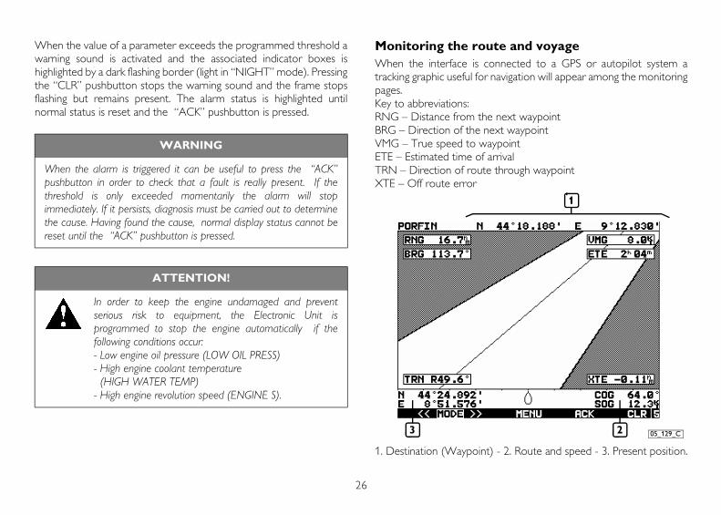
When the value of a parameter exceeds the programmed threshold awarning sound is activated and the associated indicator boxes ishighlighted by a dark flashing border (light in “NIGHT” mode). Pressingthe “CLR” pushbutton stops the warning sound and the frame stopsflashing but remains present. The alarm status is highlighted untilnormal status is reset and the “ACK” pushbutton is pressed.
Monitoring the route and voyage When the interface is connected to a GPS or autopilot system atracking graphic useful for navigation will appear among the monitoringpages.Key to abbreviations:RNG – Distance from the next waypointBRG – Direction of the next waypointVMG – True speed to waypointETE – Estimated time of arrivalTRN – Direction of route through waypointXTE – Off route error
1. Destination (Waypoint) - 2. Route and speed - 3. Present position.
WARNING
When the alarm is triggered it can be useful to press the “ACK”pushbutton in order to check that a fault is really present. If thethreshold is only exceeded momentarily the alarm will stopimmediately. If it persists, diagnosis must be carried out to determinethe cause. Having found the cause, normal display status cannot bereset until the “ACK” pushbutton is pressed.
ATTENTION!
In order to keep the engine undamaged and preventserious risk to equipment, the Electronic Unit isprogrammed to stop the engine automatically if thefollowing conditions occur:- Low engine oil pressure (LOW OIL PRESS)- High engine coolant temperature (HIGH WATER TEMP)- High engine revolution speed (ENGINE S).
1
23 05_129_C

27
EN
GL
ISH
Depth monitoring (Echosounder)When the interface is connected to an echosounder, the monitoringpages will display a graph showing seabed depth changes and therelative value in metres associated with a temperature value.
Low engine oil pressure sensor efficiency testIn compliance with certification authority regulations, systemequipment includes devices that check alarm operating efficiency. Anexample is the oil shut-off tap (2) on the “Low oil pressure” (WA)sensor fitting, used to check the efficiency of the associated function.
05_130_C05_131_C
1
2

28
Replacing the engine control unit To offer a higher level of safety during voyages on vessels equippedwith a single engine, it is necessary to provide a second auxiliaryelectronic engine control unit (1, diagram previous page) alongside theelectronic control unit to allow rapid replacement in case of damage.The procedure for removing and inserting the connectors required touse the auxiliary electronic unit is as follows
REMOVAL OF ECU CONNECTORS
INSERTION OF ECU CONNECTORS
80802A
80802B

29
EN
GL
ISH
MANAGING C13 ENS M33 - ENT M50 ENGINES FROM RELAY BOXThe following functions can be managed through the “Relay box” unit,which is usually installed close to the machine room :
Engine start-up and shut-down.
Control post selection: bridge or engine room.
Revolution speed increasing and decreasing.
Self-diagnosis test (only for Customer Service Network).
1. Control post selection - 2. Start/stop control - 3. Manual accelerator -4. Accelerator push button enabling (3) - 5. Blink code emission pushbutton - 6. EDC fault signaling led and blink code - 7. Diagnosis toolconnector.
Startup procedure1. Turn the switch to 1 ENGINE ROOM. The START-STOP (2) push
button nearby is enabled; this action disables any function ofon boardpanels located on the bridge and fly-bridge.
2. Press the 2 push button to ENGINE START position and release itupon startup.
Speed management procedure1. Turn the 4 switch to PTO ON position;
2. To speed up: press and hold the 3 button in the PTO+ positionuntil the required speed is reached, then release it.
3. To speed down: press and hold the 3 button in the PTO- positionuntil the required speed is reached, then release it.
Once the required speed has been reached, it will be maintained untilthe 4 switch is turned to PTO OFF position or the engine is stopped.
6 704_002_C
1 2 3 4 5
WARNING!
When the engine is rotating, do not operate the ENGINEROOM / BRIDGE switch.

30
Stop procedure1. Press the 2 push button to STOP position until the engine is
completely stopped.
2. Bring the switch 1 back to BRIDGE position to allow for the use ofcontrols located on the on board panels and to inhibit the use ofthe START-STOP button of the "Relay box".
Self-diagnosis procedureThe use of the CHECK (5) push button allows the Customer ServiceNetwork to read the self-diagnosis information save in the Engineelectronic control unit. The 6 LED will show the code by blinking.
MANAGING THE C13 ENT M77 ENGINE FROMRELAY BOXThe engine fitting includes a "Box relay" unit which is usually located nearthe engine room and which provides management of the followingfunctions:
Start and stop.
Control post selection: bridge or engine room.
Revolution speed increasing and decreasing.
Self-diagnosis test (only for Customer Service Network).
1. Control post selection - 2. Start/stop and manual speed-up control -3. This button is not active - 4. Led not used with this fitting - 5. Diagnosistool connector.
WARNING!
When the engine is rotating, do not operate the ENGINEROOM / BRIDGE switch.
1 2 3
4
5
04_074_N

31
EN
GL
ISH
Startup procedure1. Turn the switch to 1 ENGINE ROOM. The START-STOP (2) push
button nearby is enabled; this action disables any function ofon board panels located on the bridge.
2. Press the 2 push button to START position and release it untilstartup is obtained.
3. To speed down: press and hold the 2 button in the START positionuntil the required speed is reached, then release; if repeated actiontoggles speed up and speed down. The speed reached at eachchange will be maintained until the next change or the engine stop.
Stop procedure1. Press the 2 push button to STOP position until the engine is
completely stopped.
2. Bring the switch 1 back to BRIDGE position to allow for the use ofcontrols located on the on board bridge panels and to inhibit theuse of the START-STOP button of the "Relay box".
FOR A CORRECT USE OF THE ENGINEDo not extend the startup control when the engine is started.
Do not remain at the quay to wait for engine warm-up. Afterstartup slowly start navigation. The correct operating temperaturesare reached with the engine running at medium power.
Do not proceed too long at slow speed as it enhances theproduction of harmful engine emissions and does not guarantee itsbetter performance.
Engine speed-up and speed-down should be performed graduallyin order to allow a regular combustion and a better performanceof all engine organs.
Cruising maximum speed should not exceed 90% of maximumpower (see ENGINE TECHNICAL DATA).
During navigation check that:
• Engine coolant temperature does not reach alarm thresholds.
• Oil pressure is kept within the normal values provided.

32
SPECIAL WARNINGS
Coolant high temperatureIn case the temperature on the instrument is excessive or an alarm isoff, reduce speed and return to the harbor and check the sea waterintake and cooling circuits status. The following should also bechecked:
• water and alternator belts tensioning.
• thermostatic valve operation.
• cleaning of heat exchangers.
Low lubricant pressureIn case the pressure reading on the instrument is considered notsufficient or if a "Low oil pressure" led turns on, stop the engine andcheck the oil level. Refill if necessary (see section CHECKS andMAINTENANCE).Should signaling persist, return at low speed and contact an authorizedCustomer Care Center.
Water in the fuel pre-filterIt's a good habit to drain the water inside filters before the relevant ledturns on.Avoid using the engine when the tank contains only the reserve fuel;such condition fosters the formation of condensation and the suctionof sludge or air, causing the engine to stop.
Air filter clogging and inefficient exhaust circuitRegularly inspect the cleaning of air suction inlets and exhaust piping.Maintenance intervals contained in this manual only take intoaccount the performances of the engine parts and not of those partsmanufactured at the Yard or any other external intervention.
WARNING!
When the engine is hot, inside the cooling circuits apressure is generated which can cause the sudden exit ofthe hot liquid, generating burn hazards. Open the coolantpan refill cap only if necessary and exclusively when theengine is cold.
WARNING!
Use the utmost care when refueling and avoid liquid orsolid polluting agents to enter the tank. It is reminded thatsmoking or ignition of flames is prohibited during refueling.
WARNING!
Visually check that the exhaust circuit is not obstructed ordamaged in order to avoid formation of hazardous fumesinside the hull.

33
EN
GL
ISH
Battery or alternator recharging faultPeriodically check or have checked the cleaning, wear and tensioningcondition of the tensioning belt.
Anomalies in the electrical systemPeriodically check, especially during the winter, the cleaning andefficiency condition of batteries. Proceed by checking and refilling asdetailed in the CHECK AND MAINTENANCE section and observethe warning therein. In case batteries are replaced, observe thefeatures detailed in GENERAL section.
RUNNING-INThanks to the engine construction advanced technology, non specialrunning-in procedure is required. However it is recommended toavoid at least for the first 50 hours, using the engine at high speeds forextended periods of time.WARNING!
Tensioning parts are protected with safety casing. Removethem only when the engine is not running.
WARNING!
Contact a specialised office and check battery and recharging systemefficiency if the voltmeter indicates a voltage below 11 V (for 12 Vrated systems), or 22 V (for 24 V rated systems).

34
REFUELING
(*) Does not refer to C13 ENS M33 engine.
(1)Use a water and PARAFLU 11 mixture at 50% also during summer.As an alternative to PARAFLU 11, use a product complying withSAE J 1034 international standards.
(2)Use lubricants complying with the following international specifications:ACEA E3 - E5 (high power engines ), API CF - CH4 (associated to fuelswith a sulfide percentage of < 0,5%), MIL - L - 2104 F.
The grade of viscosity to be used in relation to environmenttemperature can be found in the table in the appendix.
The oil consumption is considered as acceptable up to a quantityequal to 0.5% of fuel consumption.
(3)The quantities shown refer to the first refueling and concern therefilling of engine, oil pan and filter.
(4) Use only commercially available diesel oil (complying with EN 590standard). Use of additives is recommended. Use of fuel derivedfrom the synthesis of organic substances and vegetable oils(Biodiesel) is not allowed.
Low temperature diesel oilThe DIN EN590 distinguished different classes of diesel oil andidentified the characteristics of those more suitable for being used atlow ambient temperatures.It is the Oil company's responsibility to observe the regulationsgoverning the distribution of fuels suitable to the climatic andgeographic conditions in the different countries.
Marine gear oil refuelingFor the quantity and type of oil to be used in the marine gear, consultthe manual supplied by the Manufacturer.
Parts to be refueled C13 ENT .... C13 ENSliters (kg)
Cooling circuit(1) 45
Cooling circuit(2):Total capacity(3)
Periodical replacementOil pan at minimum levelOil pan at maximum level
42 (38)38.5 (35)29 (26.3)36 (32.6)
Fuel tank(4) -
WARNING
Refuelling from drums or tanks may pollute diesel oil and thereforedamage the injection system. If necessary filter or settle impuritiesbefore refueling.

35
EN
GL
ISH
INSPECTIONS AND MAINTENANCE
MAINTENANCE STAFFEngine inspection and maintenance interventions described in thefollowing section require training, skills and the observance of thesafety regulations provided. Therefore only spacialized staff canperform them as specified below.
Inspections: shop operators or boat user if necessary.
Periodical maintenance: qualified staff, equippedwith suitable tools and protection gear. Interventionsmarked with a wrench (see picture).
Extraordinary maintenance: Authorized ServicingCenters' qualified staff having the specific technicalknow-how and equipment. Interventions marked witha wrench (see picture).
Authorized Servicing Centers are members of IVECO MOTORSCustomer Care Network.
ACCIDENT PREVENTIONAlways wear safety shoes and gear.
Do not wear loose garments, rings, bracelets and/or necklaces nearthe engines or moving parts.
Wear safety gloves and goggles when:
• refilling batteries with acid solution
• refueling with inibitors or deicers
• replacement or refueling of lubricant (hot engine oil can causeburns. Proceed with interventions only when it has reached atemperature lower than 50°C).
When performing interventions inside the engine housing, useutmost care when moving in order to avoid contact with rotatingor high temperature items.
Wear safety goggles when using compressed air (the maximumcleaning air pressure is 00 kPa (2 bar, 30 psi, 2 kg/cm2).
Wear a hard safety hat if you work in an area with suspended loads.
Use protective hand cream.
Immediately replace wet overalls.
Keep the engine always clean and eliminate oil, diesel and coolantstains.
Place greasy rags in fireproof containers.
Do not leave foreign bodies on the engine.
Use suitable and safety container for exhaust oil.
When the repair is finished, take the necessary steps to stop engineair suction in case, after start-up, an unrestrained increase of enginerevolution occurs.

36
FREQUENCY
The following frequencies take into account use factors that are typicalof the different uses of the engine. The most suitable maintenancefrequency will be specified by the maintenance staff based on the useand operating conditions of the engine.
WARNING!
Avoid performing maintenance near a power source:check that the equipment is efficiently grounded. Duringdiagnosis and maintenance operations make sure handsand feet are dry and always use insulating footboards.
Checks during periods of use Frequency
Engine lubricant level inspection Daily
Inverter lubricant level inspection Daily
Engine coolant level inspection Daily
Exhaust pipe/s integrity inspection Daily
Water drain from fuel pre-filter 150 hours (1)
Inspection/restoring battery electrolyte solution level and cleaning of terminals
Every six months
Periodical maintenance: Frequency
Air filter/s cleaning 300 hours (2) (7)
Zinc anodes corrosion 300 hours (4) (7)
Oil vapor filter status(an indicator may be available)
300 hours (7)
Condensation draining/suction from fuel tank/s
300 hours (1) (7)
Engine lubricant replacement 600 hours (5) (7)
Unidirectional valve efficiency checkpre-lubrication system
at each replacementlubricant
Oil filter/s replacement 600 hours (5) (7) (8)
Fuel filter/s replacement 600 hours (1) (7) (8)
Fuel pre-filter/s replacement 600 hours (1) (7)
Marine gear oil replacement see relevant information
Sea water intake inspection every year
Check belt tension and conditions every year
Coolant replacement 1200 hours or 2 years
Air filter replacement 2 years
Oil vapor filter replacement 2 years (5)

37
EN
GL
ISH
1) Maximum period for using good quality fuel (EN 590 standard). It isreduced based on the dependency on fuel contamination and on thealarm signals for filter clogging and/or water in the filter. The filterclogging warning requires its replacement. If the water in pre-filteralarm is not disabled after draining, the filter needs to be replaced.
2) Frequency is based on ambient and efficiency/wear conditions ofthe product. If the engine remains unused for long periods, performthe inspection before startup.
3) N.C.
4) Replace the anode only if corrosion exceeds 50% of zinc volume.
5) Frequency applicable to lubricants as provided in REFUELLINGtable.
6) Comburent air/sea water exchanger: clean both air and watersections; engine coolant/sea water exchanger: clean the sea watersection; inverter oil/sea water exchanger (if available): clean the seawater section.
7) To be performed every year even if the operating hours expectedare not met.
8) Use only filters with the following features:
- filtering degree < 12 μm
- filtering efficiency ß > 200.
Extraordinary maintenance Frequency
Check sea water pump rotor wear 1200 hours
Check the efficiency of the pre-post heating system (if available)
1200 hours
Valve-rocker arms play adjustment 1200 hours
Auxiliary elements belt replacement 1200 hours or 2 years
Cleaning of heat exchangers 1200 hours or 2 years (6)
Supercharger cleaning 1200 hours or 2 years (5)
WARNING
In case fuel sulfur percentage exceeds 0,5% or oils not meeting thespecifications provided in refueling table are used, oil, engine oil filterand oil vapor filter frequencies should be halved or adjusted to theengine use and operating conditions; for more information please referto maintenance staff.

38
PRESCRIPTIONSDo not disconnect battery power when the engine is running.
Do not perform arch soldering near the engine without havingremoved al electric connections and electronic units.
After each service, check that clamps have been securely replacedon terminals after disconnection of the battery.
After each maintenance involving disconnection of battery clamps,make sure they have been securely tightened on the relevant poles.
Do not start the engine using the battery charger.
Disconnect batteries from on board power source while they arebeing recharged.
Do not paint equipment, components and electrical connectors ofthe engine fitting.
Disconnect batteries from power source before any electricalintervention.
Before on board installation of any electronic equipment, contactthe Yard (two-way radio, echo sounder).
HOW TOEngine lubricant level inspectionTo avoid risk of burns only proceed when the engine is not runningand is cool.
Using the dip stick (1), that the oil quantity is included between"Min" and "Max" limits.
Refill if level is insufficient, using the hole on top of cylinder head.Remove the cap (2).
3205_008_C
1

39
EN
GL
ISHMarine gear lubricant level inspection
Check oil level in the marine gear. Follow the instructions provided inthe manual provided by the marine gear manufacturer.
Coolant level inspectionProceed only with engine not running and at low temperature to avoidany risk of burns.
Remove the filling pan pressure cap (3 in the previous page)
Visually check that the fluid level is a few centimetres below thefiller hole.
If necessary, top up the reservoir using a mixture as shown in theREFUELING table. Do not completely fill the reservoir.
Exhaust pipe/s integrity inspectionVisually check that the discharge system of exhaust gases is not cloggednot damaged.
Make sure there is no dangerous fumes inside the hull. Contact theYard if necessary.
Water drain from fuel pre-filterThe high risk of refueling with fuel polluted with foreign bodies andwater requires inspections to be performed even if no alarm istriggered on the on board panel.Proceed with engine not running.
Place a basin under the pre-filter inorder to collect liquids.
Unscrew the cock plug (1) located inthe pre-filter lower section; in somefittings the plug includes the diesel oilwater sensor.
Drain the liquid until it is detected as“diesel oil” only.
Manually close the plug by screwingcompletely.
Dispose drained liquids observingcurrent regulations in force.
Check the electrolyte solution level in batteriesProceed by placing the batteries on an horizontal plane.
Visually inspect that the liquid level is included between "Min" and"Max". If no reference marks is available, check that the liquid coversthe lead plates in the elements by approximately 5 mm (0.20 in).
If necessary refill only with distilled water those elements whoselevel is lower than the minimum.
Check that terminals and clamps are clean, securely tight andprotected with petroleum oil.
WARNINGS
After refilling make sure oil level does not exceed "Max" on the stick. Insert the dip stick all the way down and tighten the cap by turning
it clockwise until it comes to a full stop.
1 05_018_V

40
Some battery types are equipped with single cover for inspectionplugs. To access the items, use a lever as shown in the figure.
Air filter/s cleaningRemove the filter after removing retaining rod (1) and loosening thescrews (2) shown in the diagram.
Blow the filter with compressed and dehumidified air, from insideto outside (maximum pressure 200 kPa), or wash only with water.Avoid using detergents; do not use diesel oil.Replace if tearing is found.
Restore regular operating conditions after having placed the filter inits housing.
WARNING!
If all battery elements need topping up with a considerable quantityof distilled water, contact a specialised office and check battery andrecharging system efficiency.
WARNING!
Batteries contain sulfuric acid which is highly caustic andcorrosive. Wear safety gloves and goggles when refilling. Ifpossible, request specialized staff to perform the check.
Do not smoke nor start flames near the batteries duringchecks and make sure the room is suitably ventilated.
04_362_N
1
05_105_C
2
2

41
EN
GL
ISH
Zinc anodes corrosion inspectionProceed with engine not running and at low temperature:
Place the necessary basins in order to avoid water to spill off duringremoval of anodes.
Unscrew and remove anodes (se relevant location in ENGINETECHNICAL DATA).
Make sure corrosion does not involve over 50 % of zinc volume.Otherwise replace them.
Replace anodes in their housing and tighten to the required torque.
Oil vapor filter statusProceed only with engine not running and at low temperature to avoidany risk of burns.
With choke sensor:
If the sensor indicates that the filter is clogged, replace the filter asindicated in this document.
Without choke sensor:
Carry out disassembly as instructed for replacement..
Check that the filter element is free of deposits. Replace with anew element if deposits are present.
Refit the filter in its seat as described for replacement.
Engine lubricant replacementProceed only with engine not running and at low temperature to avoidany risk of burns.
Only with one hand pump:
Place a container to collect the exhaust oil under the hand pump(3) exit piping (2).
Open the extraction cock by vertically lifting the lever (1) B.
Unscrew the oil filler cap and operate the appropriate hand pump(3), provided for the extraction of the oil, until the oil pan iscompletely empty.
Refill oil through the hole provided on the cover. Refer toREFILLING table for the correct oil type. Tighten the plug.
4 3
A
B
1
2
05_005_C

42
Using the dip stick (4), that the oil quantity is included between"Min" and "Max" limits.
Close the cock by lowering back the lever (1) to A position.
Dispose oil observing current regulations in force.
With transfer electric system (optional)
The above operations can be performed by acting on the push buttonlocated on the electronic module. Fore safety reasons controls areenabled on only when the key switch is turned to 8A (stop).
Place under the cock (5) a container to collect the exhaust oil.
Open the cock (1) and press (A) towards DISCHARGE, until it isfully empty.
Connect the cock to the new oil container and press the buttontowards CHARGE until filling is completed.
Dispose oil observing current regulations in force.
Close the plug (1).
5 04_001_C
7
6
A
04_036_C

43
EN
GL
ISH
With transfer and pre-lubrication electric system (optional)The above operations can be performed by acting on the push buttonlocated on the electronic module. Fore safety reasons controls areenabled on only when the key switch is turner to 8A (stop).
Place under the cock (5 on next page) a container to collect theexhaust oil.
Turn the EV OFF/EV ON (B) switch to EV/ON, to the electricpump will be connected to the cock.
Open the cock (1) and press (A) to DISCHARGE, until it is fullyempty.
Connect the cock to the new oil container and press the buttontowards CHARGE until filling is completed.
To allow efficient operation of the pre-lubrication system, close thefiller/drainage tap and return switch B to the EV/OFF position.
Use the dipstick to check that the sump oil level is between the“MIN” and “MAX”.
Dispose oil observing current regulations in force.
Efficiency testing of one-way valve in the pre-lubrication system (image page 32)Proceed with engine not running.
Loosen the connection (6) and wait for the complete oil drain fromthe pre-lubrication piping.
Start the engine and check that no oil flows out of the valve (7).
Stop the engine and tighten the connection (6).
Replace the valve in case of oil leaks.
Oil filter replacementUse only filters with filtering degree equal to the above ones (seeFREQUENCY).
With traditional filter supportProceed only with engine not running and at low temperature to avoidany risk of burns, after emptying exhaust oil.
A B
04_037_C
WARNING!
Proceed with utmost care, considering the fluid hightemperature and the presence of moving parts. Always wearsuitable personal protection equipped.

44
Place under the cock (1) acontainer to collect the exhaustoil.
Remove filters.
Accurately clean surfaces.
Moist seals of the new filterswith some oil.
Manaully tighten until contact ismade, then tighten again for 3/4of turn.
Dispose drained liquidsobserving current regulations inforce.
With filter support and exclusion levers (optional)The support with exclusion lever allows replacing the filter also withrunning engine.
Rotate the lever (2) corresponding to the filter to be replaced, toCLOSED as shown on the relevant plates.
Proceed as with the traditional filter.
Bring the lever back to “OPEN” position.
WARNING!
Proceed with utmost care, considering the fluid hightemperature and the presence of moving parts. Always wearsuitable personal protection equipped.
05_006_C
1
WARNING!
Do not exclude both filters at the same time to avoid anydamage.
2 2
04_042_C

45
EN
GL
ISH
Fuel filter/s replacementProceed only with engine not running and at low temperature to avoidany risk of burns.Use only filters with filtering degree equal to the above ones (seeFREQUENCY).
With traditional filter support
Remove filter (1) by unscrewing it.
Moist seals of the new filters with diesel or engine oil.
Manually tighten until contact is made, then tighten again for 3/4 ofturn.
Loosen the bleeding connection on the filter support and act onthe hand pump of the pre-filter until fuel flows out without air.
Tighten the connection and start the engine acting on the pump,also during the first startup phases.
NOTE: to speed up automatic bleeding of residual air, loosen thefitting on the cylinder head (2) during the initial start-up, tightening itwhen start-up has taken place.Ensure that the fuel emerging from the fitting does not dirty theauxiliary drivebelt and is not dispersed into the atmosphere.
With filter support and switching lever (optional)The support with switching lever allows replacing the filter also withrunning engine.
Switch the lever (3, on next page) to A and replace the filter (5, onnext page).
Switch the lever (3, on next page) to B and replace the filter (4, onnext page).
Proceed as with the traditional filter.
Bring the lever back to central position to avoid limiting the fueldelivery to the injection system.
2
1
05_001_C
WARNING
Do not fill the new filter before placing in on the support, to avoidallowing impurities to enter and damage the circuit and the injectionsystem.

46
Fuel pre-filter/s replacementProceed only with engine not running and at low temperature to avoidany risk of burns.
Remove water presence sensor (3).
Unscrew the water sensor (3)from the old pre-filter.
Check that the new filter matchesthe engine requirements.
Moist seals of the new filters withdiesel or engine oil.
Manually tighten until contact ismade, then tighten again for 3/4 ofturn.
Replace the water sensor andcheck that threads match.
Unscrew the bleeding connection(2) act on the manual pump (1)on the pre-filter support until thecircuit is full.
Start the engine and keep itrunning at idle to remove airexcess.
Check pre-filter support (4) grounding.
WARNING!
Proceed with utmost care, considering the fluid hightemperature and the presence of moving parts. Always wearsuitable personal protection equipped.
5
3
4
04_041_C
A B
05_018_V
1
3
2
4

47
EN
GL
ISH
Check tension and conditions of auxiliary parts beltProceed only with engine not running and at low temperature to avoidany risk of burns.
Remove pulley protection.
Check that there are no tears in the belt and that it shows noobvious signs of wear and tear or of soiling from oil or fuel. Replacebelt if these signs are present.
Check tensioner efficiency by applying the tool to the tensioner asshown in the figure.
Replace casing and tighten fastenings.
Coolant replacementProceed only with engine not running and at low temperature to avoidany risk of burns.
Use basins to avoid coolant dispersion in the environment.
Remove plugs on the circuit and wait for it to bleed completely(see ENGINE TECHNICAL DATA for location). When empty,replace the plugs back in their seats replacing the gaskets.
Refill the circuit as described in REFILLING table.
Degas and refill the circuit as instructed in section PRESCRIPTIONSFOR FIRST START-UP.
Oil vapor filter replacementProceed only with engine not running and at low temperature to avoidany risk of burns.
Remove engine fittings to access filter housing.
Loosen screws, remove filter housing cover (1).
Remove and dispose the filter (2) observing current regulations inforce.
Slide the new filter, observing the assembling direction. Reinforcingitems (3) should be visible.
Replace the cover on its housing and replace the componentsremoved to restore the engine to its original specification.
05_070_C

48
Condensation draining/suction from fuel tank/sSea water intake inspectionCheck sea water pump rotor wearCheck the efficiency of the pre-post heating systemValve-rocker arms play adjustmentCleaning of heat exchangersSupercharger cleaning
See the marine gear Manufacturer's handbook.
WARNING!
The filter (2) has unidirectional efficiency and should beplaced with the two reinforcing items visible (3) as shown inthe picture.
84377
13 2
WARNING
Only IVECO MOTORS Servicing Centers or Yard staff may perform thefollowing operations.Please refer to the relevant technical and repair manuals.

49
EN
GL
ISH
MOVING THE ENGINEOnly Authorized Servicing Center staff can perform such operations.To lift only the engine use the eyelets specified herein in theENGINE TECHNICAL DATA section.Lift using a rocker arm and keep ropes parallel, using the eyeletsprovided simultaneously. Use in smaller quantities than specified is notpermitted. The engine lifting system should be suited to the engineweight and clearance. Make sure there is no interference between thelifting system and engine organs.Do not lift the engine before removing its transmission organs.
EXHAUST PARTS DISMISSALThe engine assembly includes parts and items which may causeecological damages if released in the environment.The materials listed should be delivered to special collection centers.Current regulations in different countries provide for severepunishment of transgressors.
Start-up batteries.
Exhaust lubricant oils.
Water and deicer mixtures.
Filters.
Cleaning auxiliary material (ex. greaser rugs or soaked with fuel).

50
LONG ENGINE INACTIVITY
ENGINE PREPARATION FOR LONG INACTIVITYPERIODSIn case of prolonged inactivity and order to avoid oxidation of internalparts of the engine and of some components of the injection system,prepare the engine as follows:
1. Drain the lubricant oil from the pan, after warming up the engine.
2. Fill with 30/M protective oil (or an oil compliant with MIL 2160Btype 2 specifications) until "minimum" level is reached on the dipstick. Start the engine and keep it running for 5 minutes.
3. Bleed the fuel from the injection circuit, the filter and from theinjection pump piping.
4. Connect the fuel circuit to a tank containing protective liquid CFB(ISO 4113) and run the engine for 2 minutes after cutting out theinjection system. This can be done by energizing terminal 50 on thestarter with positive voltage equal to the system rate voltage, usinga conductor.
5. Spray approximatively 80 g of protective oil 30/M (10 g per liter ofswept volume) on the supercharger suction intake, during theabove motoring.
6. Close with plugs or seal any opening.
7. Drain any residual 30/M oil. Store for future use (enough for 2preparations).
8. Apply ENGINE WITH NO OIL labels to the engine and on boardpanel.
9. Drain coolant, and place a label stating the operation has beencompleted.
In case of extended inactivity, repeat the above every 6 month, asfollows:
A) Drain from 30/M protective oil;
B) Repeat from step 2.
In case protection of engine external parts is required, spray allunpainted surfaces with OVER 19 AR protection liquid, avoiding belts,cable connections and electric parts.

51
EN
GL
ISH
COMMISSIONING AFTER AN EXTENDED PERIOD OF INACTIVITY1. Drain any residual 30/M protective oil.
2. Fill the engine with lubricating oil as provided in REFUELLING table.
3. Drain any protective liquid from the fuel circuit and follow theinstructions provided in point 3 ENGINE PREPARATION FORLONG INACTIVITY PERIODS.
4. Remove any closing and/or sealant. Connect the superchargerintake to the air filter.
5. Connect fuel circuits to the boat tank and follow the instructionsprovided in point 4 in ENGINE PREPARATION FOR LONGINACTIVITY PERIODS.
6. Check and refill the engine with coolant, as instructed.
7. Start the engine and keep it running until idle speed is stable.
8. Check that readings are acceptable and that no alarm is on.
9. Stop the engine.
10.Remove ENGINE WITH NO OIL labels from the engine and onboard panel.
FIRST START-UP AFTER LONG INACTIVITY PERIODS1. Refill the engine as provided in REFUELLING table.
2. Remove the sacrificial anode (1) and fill with 1.5 liters of water, inorder to start the sea water pump.
3. Place the anode back into its housing and tighten as provided.
4. Degas the cooling circuit as follows:
Leave the engine idling and carefully loosen the screw (2) positionedon the coolant reservoir beside the cap and the two screws (3)positioned on the exhaust manifold to help bleed any remaining air.After sufficient time, tighten the screws to the recommendedtorque, shut down the engine and recheck coolant level, topping upif necessary. Do not disperse in the environment any liquid.
2
1
3
05_001_C
52
ENGINE FAULTS
The electronic unit overseeing management and control of alloperation of the engine is capable of recognising any malfunctions thatmay occur, and of adopting strategies that will allow you to navigate infull safety.The event, signalled by light-up of the EDC MALFUNCTION indicatoron the on-board control panels, results in programmed limitation ofpower whitin certain threeshold, set accordind to the severity of thecase.In the case of temporary malfunctions the reduction in performancewill remain in force until the engine is stopped.
Fault in the accelerator electronic circuitWhen the CENTRAL ELECTRONIC UNIT detects any fault, thestrategies specified in "Accelerated minimum idle speed" sectionshould be adopted, in order to proceed with emergency navigation.Available operating modes are:
A. Accelerator lever “not responding”: revolution sets to 750 rpm toallow slow navigation and maneuvering operating only on theinverter, without accelerating.
B. The accelerator lever “responds partially”: engine speed with thelever at minimum is equal to 750 rpm. If you bring the acceleratorto half way of its travel, the speed progressively increases to 2000rpm. If you bring back the lever, speed will go rapidly back to 750rpm.
NOTE: The “A” mode allows using higher speeds and managingstart/stop functions as detailed in ENGINE OPERATION FROMRELAY BOX. Always, observe accident prevention precautions detailed inINSPECTIONS AND MAINTENANCE.
WARNING!
The engine electronic unit may adopt safety strategies anytime during navigation, whenever any risk condition for theengine is detected. When such conditions arise, proceed with utmost care,and check that everyone on board is holding on securely.
WARNING!
Engine operation from “Relay box” disables bridge controls;therefore from the bridge the only way to stop theengine is to act on the inverter disconnect lever.

53
EN
GL
ISH
EMERGENCY ON BOARD
The boat user, if observing the instructions contained in this manual,will always be acting in safe conditions.In case of accident, always request the immediate intervention ofrescue staff.The following is to be observed In case of emergency while waiting forrescue staff to arrive.
Engine brakedownWhen navigating with broken engine, use utmost care whenmaneuvering and check that people on board is holding on securely.(see ENGINE BRAKEDOWN).
FireExtinguish using the equipment on board as required by competentauthorities (current safety regulations provide for fire equipment onboard).
Burns1. Extinguish flames on clothing using:
• water;
• dust fire extinguisher;
• blankets or rolling the victim on the floor.
2. Do not remove pieces on fabric from skin.
3. In case of burning from liquids, immediately but carefully removesoaked clothes.
4. Cover the burn with special sterile bending.
Carbon oxide intoxicationn (CO)Carbon oxide contained in exhaust gases can be very dangerous.In closed rooms it is very dangerous because it can reach dangerousconcentration is a short time.In case of intoxication in a closed environment:
1. Immediately vent the room.
2. Hold your breath when entering the room, do not turn on light, oractivate any electric device including phones , to avoid explosions.
3. Bring the injured person outside.
Electrocution The electric system does not involve electrocution however in case ofshort circuit, some risk of burn may arise. In such case:
1. Turn away the tool causing the short circuit using suitably thermallyinsulated means.
2. Turn off the mains, if available.
Injures or fracturesSeek for immediate medical help.
1. In case of strong bleeding, press the wound until first aid arrives.
2. In case of fractures, do not move the part of the body involved andtransfer the patient very carefully, and only if extremely necessary.

54
Skin burnsThis may result from contact with acid substances.This usually happens when liquid flows out of the battery. In such case:
1. Remove any soaked clothing.
2. Wash throughly with water only the parts involved.
In case of eye contact with battery acid or lubricant or diesel oil: washthe eye with water for at least 20 minutes keeping your eyelids wideshut to that water flows over the ocular bulb (move the eye to everydirection for better washing).

55
EN
GL
ISH

56
ON BOARD PANELS REQUIREMENTSThe following refers to the original configuration of IVECO MOTORS equipment. The requirements and technical features of customizations may be different. Refer to the original manufacturer for further information.
(*) min. 9 V/max. 16 V referring to equipment for whichonly 12 V nominal voltage is provided.
IVECO MOTORS on board panels With analog instruments With digital instruments
Operating ambient conditions
Operating temperature range -10°C to +60°C -10°C to +60°C
Temperature limits during parking min. -20°C / max. +75°C min. -20°C / max. +75°C
Dust and rain protection degree (frontal) IP 65 – DIN 40050 – IEC 529 IP 66
Salt mist resistance (reference standard) IEC 60068-2-52 IEC 60068-2-52
Electric and electromagnetic characteristics
Operating voltage (excluding polarity inversions) min. 9 V / max. 32 V (*) min. 9 V / max. 32 V (*)
Maximum allowed over-voltage 60 V per 1 ms 60 V per 1 ms
Main panel maximum absorbed power 1.1 A (12 V) – 1 A (24 V) 310 mA (12 V) – 200 mA (24 V)
Secondary panel maximum absorbed power 400 mA (12 V) – 400 mA (24 V) 310 mA (12 V) – 200 mA (24 V)
Electromagnetic compatibility (reference standard) IEC 945 IEC 945
Cabling connectors requirements (reference standard) MIL 1344/1001 MIL 1344/1001
Cables requirements (reference standard)
Mechanical features
Resistance to vibrations (expressed in gravity acceleration) 1 g eff. max. -25-500 Hz (2g) 0.07 oz eff. max. -25-500 Hz
Resistance to shocks (expressed in gravity acceleration) 15 g - 1,5 ms - semi-sinusoidal wave 15 g - 1,5 ms - semi-sinusoidal wave
CEI 20/22 - CEI 20/38 - CEI 2000/532/CE