curriculum for electronics - christ university curriculum 2013-14.pdf · curriculum for electronics...
TRANSCRIPT

1
Curriculum for Electronics
UNDER GRADUATE DEPARTMENT OF
ELECTRONICS
CHRIST UNIVERSITY
BANGALORE – 560 029
2013 – 14 BATCH ONWARDS

2
Index
Title Page no.
1. Course objective 3
2. Course structure 4
3. Paper synopsis 5
4. Syllabus- semester I 7
5. Syllabus- semester II 10
6. Syllabus- semester III 14
7. Syllabus- semester IV 16
8. Syllabus- semester V 19
9. Syllabus- semester VI 23

3
CHRIST UNIVERSITY, BANGALORE-29
DEPARTMENT OF ELECTRONICS
APPROVED B.Sc. SYLLABUS
UNDER DEEMED UNIVERSITY SYSTEM (2013-14 BATCH ONWARDS)
SUBJECT: ELECTRONICS
Course Objective
The course aims at providing theoretical and practical exposure to a varied range of
electronics and communication technologies. It is diversified greatly in order to keep in
pace with recent trends and developments and the fast changing needs of the society.
The three years of study starts from the fundamentals of electronics, semiconductor
devices and applications, operational amplifiers and applications, digital electronics,
radio and television communication, satellite communication, fiber optic communication,
digital and advanced communication systems, microprocessor and microcontroller
applications, electronic instrumentation etc. Students are required to complete a project
work as a part of the curriculum.
After completing this three-year degree course, students can opt for higher studies; get
into R & D institutions like IISc, ISRO, DRDO, BEL, BHEL, ITI etc, electronics industry
or IT enabled service sections.
Methodology
Apart from conventional methods of teaching, audiovisual interactive sessions, CBT,
interaction with experts from Industry, quiz, seminars and Industry visits are adopted.
The lab sessions include systematic training in circuit designing, assembly,
measurements, trouble shooting and analysis. The individual and group projects carried
out by the students under the guidance of industry experts and teachers enable them to
develop confidence and competence in the application of electronics. Lab manuals are
prepared by the faculty and given to the students for reference.

4
COURSE STRUCTURE- ELECTRONICS UG
I SEMESTER
Course code Title Hours Marks Credits
ELE 131 Electronic Devices and Applications 4 100 3
ELE 151 Practical-I 2 50 1
II SEMESTER
Course code Title Hours Marks Credits
ELE 231 Operational Amplifiers and Linear
Integrated circuits
4 100 3
ELE 251 Practical-II 2 50 1
III SEMESTER
Course code Title Hours Marks Credits
ELE 331 Digital Electronics 4 100 3
ELE 351 Practical-III 2 50 1
IV SEMESTER
Course code Title Hours Marks Credits
ELE 431 Electronic Communication Systems 4 100 3
ELE 451 Practical-IV 2 50 1
V SEMESTER
Course code Title Hours Marks Credits
ELE 531 Computer Hardware and Verilog 3 100 2
ELE 532 Microprocessor and Interfacing 3 100 2
ELE 551 Practical-V 2 50 1
ELE 552 Practical-VI 2 50 1
VI SEMESTER
Course code Title Hours Marks Credits
ELE 631 Microcontroller and Applications 3 100 2
ELE 632 Electronic Instrumentation 3 100 2
ELE 651 Practical-VII 2 50 1
ELE 652 Practical-VIII 2 50 1

5
ELECTRONICS PAPERS
ELE 131: Electronic Devices and Applications
This paper enables the students to understand.
The basic methods of solving electrical dc networks using different network
theorems.
The designing of half wave rectifier, full wave rectifier, filter circuits and clippers
and clampers
The basic theory of bipolar junction transistor, various transistor-biasing
techniques and transistor applications
The principles of field effect transistor and applications, switching devices
ELE 231: Operational Amplifiers and Linear Integrated Circuits
This paper enables the students to understand
. The basic theory of differential amplifier and construction of Op-amp using
differential amplifiers
The Op-amp characteristics and applications
Basic principles of oscillators and applications
Principle and applications specialized ICs like 555 timer LM 317, 78xx and 79xx
series.
ELE 331: Digital Electronics
After completing this paper, students will be able to understand
Basics of number systems, codes, Boolean algebra and logic gates
Different logic families and characteristics
The design of combinational circuits
The design of sequential circuits and theory of various memory devices
ELE 431: Electronic Communication systems
This paper enables the students to understand
Principles of radio and television
The theory of transmission lines, Antennas
Basics of pulse ,digital and advanced communication systems
Theory and applications satellite communication
Theory and applications of optical fiber communication
ELE531: Computer Hardware and Verilog
This paper enables the students to understand
Fundamentals of PC and different part of a Computer
PC assembling and Disassembling

6
Basic concepts of verilog programming
Modules and various modeling techniques.
ELE 532:Microprocessor and Interfacing
This paper enables the students to understand
Basics of microcomputer and microprocessor 8085
Instruction set and Programming of microprocessor 8085
Interfacing with 8085
Features and modes of PPI 8255
ELE 631: Microcontroller and Applications
This paper enables the students to understand
Basics of microcontroller
Instruction set and Programming of microprocessor 8051
Interfacing with 8051
Features of PIC microcontroller
ELE 632: Electronic Instrumentation
This paper enables the students to understand
Performance characteristics and applications of electronic instruments
Principle and applications of electrical transducers
Signal conditioning concepts and circuits
Data acquisition and electronic instruments

7
CHRIST UNIVERSITY, BANGALORE-29
DEPARTMENT OF ELECTRONICS
APPROVED B.Sc. SYLLABUS ( 2012-13) ONWARDS
SUBJECT: ELECTRONICS
SEMESTER I
ELE 131: ELECTRONIC DEVICES AND APPLICATIONS (60hrs)
UNIT 1:DC Network Analysis (12hrs):
Review of passive components, Ohm’s law, voltage and current sources.
DC resistive networks: Transient response, RC circuit, charging & discharging of
capacitor in RC circuit, derivation for instantaneous charge, voltage and current in the
circuit. meaning of time constant , expression, graphical representation. numerical
problems.
RL circuit , growth and decay of current, derivation for instantaneous current in the
circuit. meaning of time constant , expression, graphical representation. numerical
problems.
Network Theorems: voltage divider theorem, current divider theorem , Kirchoff’s Laws
(loop equations only), superposition theorem, Thevenin’s theorem, Norton’s theorem,
conversions, maximum power transfer theorem – statement, explanation, numerical
examples.
UNIT 2: Diode Applications (13 hrs)
Semiconductor Diode: P-N junction, forward and reverse bias of a p-n junction, diode
symbol, V-I characteristics of p-n junction. dc forward resistance, ac forward resistance,
parameters of the p-n junction (breakdown voltage, knee voltage, maximum forward
current, peak inverse voltage, maximum power rating, bulk resistance).
Zener diode: Equivalent diagram of zener diode. zener and avalanche breakdown
mechanisms in diodes, zener diode characteristics. zener diode as voltage a regulator-
line and load regulation, expression for Rs(min), Rs(max), Iz(max), Iz(min) (no
derivation), numerical problems.
Rectifiers: Half wave rectifier, center tap full wave rectifier and bridge rectifier –circuit
diagram, working, input and output wave form, expression for Idc, Irms, ripple factor,
efficiency (no derivation), PIV of diode and frequency of output in each case. advantages
and disadvantages of each type of rectifiers, comparison of rectifier circuits, numerical
problems

8
Filter circuits :Types of filters: series inductor filter, shunt capacitor filter, LC filter, ∏
filter, circuit diagram, input and output wave form, expression for ripple factor (no
derivation), performance and comparison.
Voltage Multipliers: Half wave voltage doubler, full wave voltage doubler, voltage
tripler - circuit diagram and working.
Clipping circuits and Clamping circuits: Positive clipper, negative clipper, biased
clipper, and combinational clipper, circuit diagram and working, input and output wave
form, positive clamper and negative clamper, input and output wave forms, numerical
problems.
UNIT 3: Bipolar Junction Transistor (06 hrs)
Introduction to transistors-Transistor construction, transistor symbol, different methods
of transistor biasing, operation of NPN and PNP transistor, transistor currents, input and
output characteristics of CE configuration. comparison of CE, CB and CC configurations.
Transistor Biasing: Need for biasing, The dc operating point and load line, factors
affecting stability of Q point, stability factor definition.
Methods of transistor biasing: Fixed bias, fixed bias with emitter resistor and voltage
divider bias circuits-circuit diagram, explanation, derivation for operating point and
stability factor, advantages and disadvantages. Numerical problems
UNIT 4: Transistor Applications (14hrs)
Transistor as an amplifier: Classification of amplifiers. small signal operation of CE
amplifier: various circuit current, phase reversal, ac and dc equivalent circuits, re model,
derivation of input resistance, output resistance, current gain, voltage gain, power gain,.
hybrid parameters (qualitative), expression for hfe, hie, hre, hoe, numerical problems
Multistage Amplifiers: Introduction, gain of multistage amplifier, decibel gain .power
gain, types of coupling, analysis of a two stage RC coupled amplifier, frequency
response, expression for over all gain (no derivation) , band width, advantage and
disadvantage of RC coupling, direct coupled amplifier, frequency response, calculation of
voltage gain., advantages and disadvantages of direct coupling
Power Amplifiers: Introduction, difference between voltage and power amplifiers, ac
load line, classification of power amplifiers, Class A amplifier: power relation in Class A
amplifier, overall efficiency of class A amplifier, resistive load and transformer coupled,
over all efficiency of transformer coupled class A amplifier, limitations. Class B
amplifier: characteristics, push-pull operation, maximum efficiency of class B push –pull
amplifier, crossover distortion, and complementary symmetry amplifier, working
numerical examples
Transistor Tuned Amplifier: Need for tuned voltage amplifier, resonance- series and
parallel, impedance, resonance curve, characteristics of series resonance, single tuned
voltage amplifier, frequency response of single tuned voltage amplifier, advantage and

9
limitation of single tuned amplifiers, double tuned voltage amplifier, frequency response
of double tuned voltage amplifier, limitations and applications.
UNIT 5: Field –Effect Transistors (10 hrs)
Construction and working of JFET, drain characteristics, transfer characteristics, JFET
parameters, FET approximation- Shockley’s equation, CS FET amplifier, working,
comparison between BJT and JFET ,numerical examples.
MOSFET: Depletion type MOSFET, construction, working, drain and transfer
characteristics, symbol.
Enhancement type MOSFET, construction, working, drain and transfer characteristics,
symbol, MOSFET applications.
Switching devices: UJT-construction, working, characteristics, SCR–construction,
working, characteristics, diac, triac- characteristics and application.
Self study Topics (5 hours)
Energy band description of semiconductors. Intrinsic and extrinsic semiconductors, p
type semiconductor, concept of hole current , n type semiconductor, n type conductivity,
p type conductivity majority and minority charge carriers.
Special semiconductor devices- Tunnel diode, Varactor diode, Schottky diode, LEDs,
seven segment display, LCD, Photo diode, solar cell.
Recommended Text Books:
1. A.P Malvino, Principles of Electronics, 7th
ed.TMH, 2011.
2. Robert L Boylestad, Introductory circuit analysis, 5th
ed.,Universal Book Stall
2003.
3.R.S.Sedha, A Text book of Applied Electronics, 7th
ed., S.Chand and Company Ltd.
2011
Reference Books:
1. T.F. Bogart. Beasley, Electronic Devices and circuits, 6th
ed, Pearson Education, 2004.
2. N.N. Bhargava, D.C Kulshreshta, and S.C Gupta, Basic Electronics and Linear
Circuits, 40th
Reprint ,TMH, 2005.
3.Robert Boystead and Louis Nashelsky, Electronics Devices and circuit theory, 8th
ed,
Pearson Education, 2004
4. T.L.Floyd, Electronic Devices and circuits, 5th
ed.PHI, fifth , 2005.
5. V.K. Metha, Rohit Mehta, Principle of Electronics, 11th
ed., S.Chand and Company
Ltd, 2011
10
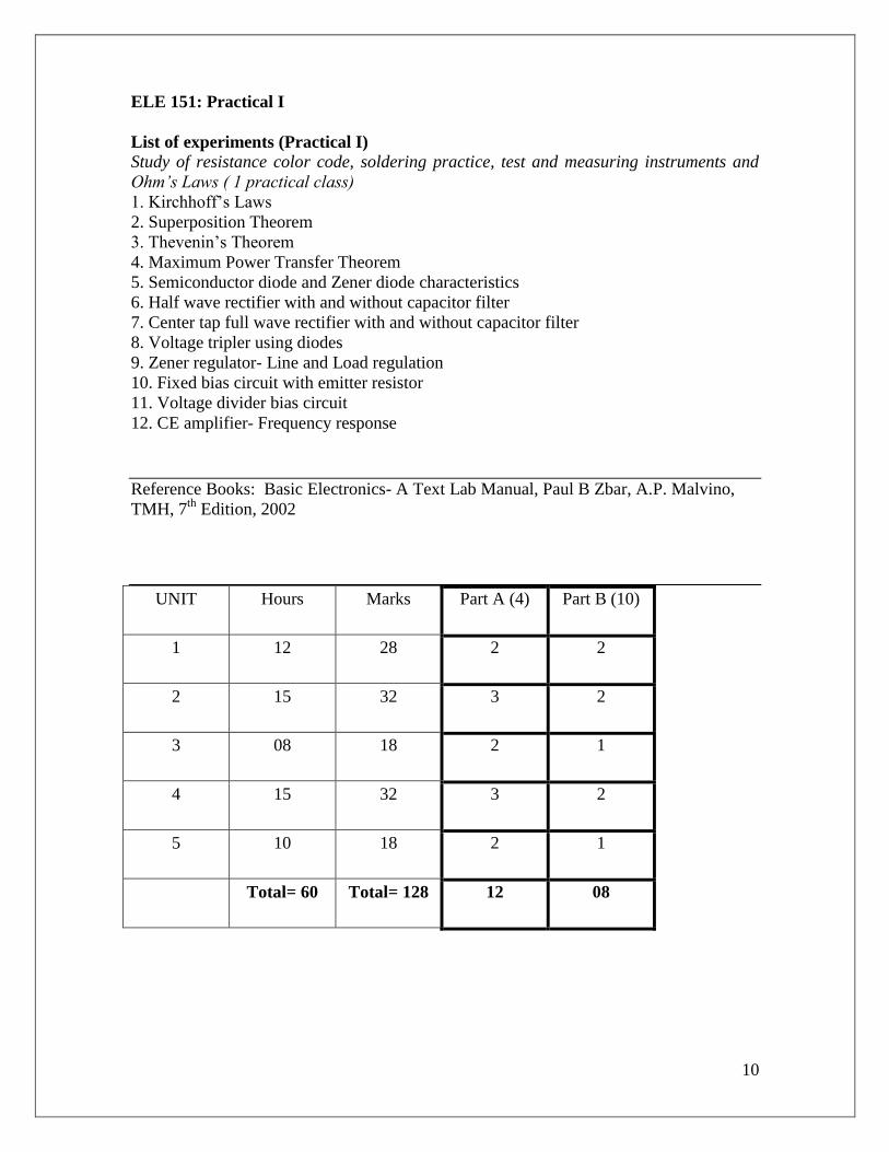
ELE 151: Practical I
List of experiments (Practical I)
Study of resistance color code, soldering practice, test and measuring instruments and
Ohm’s Laws ( 1 practical class)
1. Kirchhoff’s Laws
2. Superposition Theorem
3. Thevenin’s Theorem
4. Maximum Power Transfer Theorem
5. Semiconductor diode and Zener diode characteristics
6. Half wave rectifier with and without capacitor filter
7. Center tap full wave rectifier with and without capacitor filter
8. Voltage tripler using diodes
9. Zener regulator- Line and Load regulation
10. Fixed bias circuit with emitter resistor
11. Voltage divider bias circuit
12. CE amplifier- Frequency response
Reference Books: Basic Electronics- A Text Lab Manual, Paul B Zbar, A.P. Malvino,
TMH, 7th
Edition, 2002
UNIT Hours Marks Part A (4) Part B (10)
1 12 28 2 2
2 15 32 3 2
3 08 18 2 1
4 15 32 3 2
5 10 18 2 1
Total= 60 Total= 128 12 08

11
SEMESTER II
ELE 231: OPERATIONAL AMPLIFIERS AND LINEAR INTEGRATED
CIRCUITS
UNIT1: Differential amplifiers (5 hrs)
Differential amplifier, different types of circuit configurations, dc analysis - dual input
balanced output configurations, operating points(derivation), differential input resistance,
output resistance, voltage gain (expression, definition)) , comparison of different
configuration of differential amplifier, inverting and non inverting inputs, CMRR,
expression, current mirror circuit, differential amplifier with current mirrors, current
mirror as tail current, current mirror as active load.
UNIT 2 : Op-amp theory(10 hrs)
Op-amp block diagram, equivalent circuit, pin diagram of IC 741, specification,
characteristics of ideal and practical op-amp, op-amp parameters- input bias current,
input offset voltage, output offset voltage, slew-rate, open loop op-amp, limitations, op-
amp negative feedback, block diagram of a voltage series, voltage shunt, current series,
current shunt feedback circuits, inverting and non-inverting voltage feedback- circuit,
derivation for voltage gain(In terms of open loop voltage gain, in terms of feedback
resistance), input and output impedance (circuit diagram and derivations). virtual ground,
bandwidth..
UNIT 3: Op-amp applications (10 hrs)
Adder- inverting and non-inverting, subtractor, scale changer, buffer, comparator- basic
comparator, zero cross detector and Schmitt trigger, comparator characteristics,
numerical problems
Active Filters: Classification of filters, advantages of active filters, types of filters. first
order Butterworth filters: low pass, high pass, gain derivation and frequency response,
filter design (problems), frequency scaling ,second order Butterworth low pass and high
pass filters, voltage gain (no derivation), frequency response graph, band pass, band
reject and all pass filter, circuit diagrams and frequency response.
UNIT 4: Oscillator circuits (15 hrs)
Sinusoidal Oscillators:
Classification of oscillators, basic principle, block diagram of feedback circuit,
negative feedback, positive feedback explanation, expression of gain with positive
feedback, explanation of damped, growing and sustained oscillations with sine wave.
Barkhausen criterion for sustained oscillations. noise voltage as starting voltage.
concept of parallel resonance. LC tank circuit, principle , damped and undamped
oscillation, expression for frequency in terms of L & C. necessary conditions for
sustained oscillations.

12
Transistor Oscillators:
Hartley oscillator: Circuit diagram, explanation, circuit operation, expression for-
frequency of oscillation, feedback ratio, gain for sustained oscillation.(no derivation).
numerical problems.
Colpitt’s oscillator: Circuit diagram, explanation, circuit operation, expression for-
frequency of oscillation, feedback ratio, gain for sustained oscillation.(no derivation).
numerical problems.
Limitations of LC oscillators.
Op- amp Oscillators:
RC oscillators, basic principle of RC oscillators, phase shift oscillator- circuit diagram,
principle, working, expression for frequency of oscillation, feedback ratio, gain for
sustained oscillation (no derivation), numerical problems.
Wien bridge oscillator – circuit diagram, principle, working, expression for frequency of
oscillation, feedback ratio, gain for sustained oscillation (no derivation), numerical
problems.
Crystal oscillators- Piezo electric effect, equivalent circuit of crystal and applications.
Non-sinusoidal Oscillators:
Classification of non-sinusoidal oscillators, transistor as a switch, transistor
multivibrators, types of multivibrators.
astable multivibrator- circuit diagram, waveforms, circuit operation, ON time, OFF time
expressions, expression for frequency of oscillation, numerical problems. applications.
monostable multivibrator- circuit diagram, waveforms, circuit operation, expression for
pulse width. applications.
bistable multivibrator-. circuit diagram, waveforms, circuit operation, applications.
square wave generator using op-amp.
UNIT 5: Specialized IC applications (15 hrs)
IC 555 timer:
Pin diagram, functional block diagram, explanation
Astable multivibrator- circuit diagram, schematic diagram, waveforms, expressions for
charging time constant, discharging time constant, duty cycle and frequency of
oscillation, numerical problems. applications.
Mono-stable operations- circuit diagram, schematic diagram, waveforms, expressions for
pulse width. applications.
Voltage controlled oscillator, Schmitt trigger- circuit diagram, schematic diagram,
waveforms, saw tooth generator , circuit diagram, schematic diagram, waveforms,
Phase-locked loop - operating principle, block diagram, explanation. monolithic PLL-IC
565, pin diagram, functional block diagram 565 PLL, application in frequency
multipliers.

13
power amplifiers using power boosters. monolithic power amplifiers – LM 380 as power
audio amplifier.
voltage regulators, fixed and variable, 78xx series and 79xx series, working, pin out
diagram and applications.
IC LM 317 as a variable voltage regulator, numerical problems.
switching regulator-block diagram, explanation.
power supply- block diagram explanation, circuit diagram and explanation for +5V and
-5V supply design.
Self Study Topics (5 hrs)
Introduction to IC’s: Advantages, limitations, linear and digital ICs, examples, scale of
integration, development of ICs, fabrication techniques, latest trends in IC technology.
Special purpose op-amps- specification, characteristics and comparison, interpretation of
data sheets
Feedback in amplifiers, types of feedback, advantages and disadvantages, applications
Recommended Text Book:
Ramakanth Gayakwad, Operational amplifier and linear circuits, 3rd
ed.,PHI, 2005.
Reference Books:
1. T.F. Bogart and Beasley, Electronic devices and circuits, 6th
ed.,Pearson Education,
2004.
2. A.P Malvino, Electronics principles, 7th
ed.,TMH, 2011.
3. T. L. Floyd, Electronic devices and circuits, 5th
ed.,PHI, 2005.
4. Sedra and Smith, Micro electronics circuits , 5th
ed, Oxford University Press, 2001
ELE251: Practical II
List of experiments
1. Colpitts oscillator
2. Construction of regulated power supply using IC 7805 and IC 7905
3. Op-amp adder, subtractor and scale changer
4. Phase-shift oscillator using IC 741
5. Wien-bridge oscillator using IC 741
6. Op-amp comparator
7. Hartley oscillator
8. Astable multivibrator using transistors
9. Current and voltage regulation using IC LM 317
10 Op - amp inverting amplifier
11 Crystal oscillator
12. Monostable multivibrator using IC 555

14
Reference Books: Paul B Zbar, A.P. Malvino, Basic Electronics- A Text Lab Manual,
TMH, 7th
ed.,TMH, 2002
BLUE PRINT
II Semester
UNIT Hours Marks Part A (4) Part B (10)
1 5 14 1 1
2 15 32 3 2
3 10 18 2 1
4 15 32 3 2
5 15 32 3 2
Total= 60 Total= 128 12 08
SEMESTER III
ELE 331: DIGITAL ELECTRONICS ( 60 Hrs)
UNIT 1: Number systems: (6 hrs)
Decimal, binary, octal and hexadecimal and their inter conversion. digital codes, BCD
(8421) code, gray, excess 3, alphanumeric codes-ASCII, Arithmetic operation in binary
and hexadecimal, BCD addition, and excess 3 addition,
Sign magnitude conversion, 1’s and 2’s complements subtraction, signed number
arithmetic addition.
UNIT 2: Logic gates and Boolean algebra (12 hrs)
Positive and negative logic, basic logic gates, AND, OR and NOT gates, Boolean
algebra-laws and theorems, NAND and NOR gates, De-Morgan’s theorems, XOR and
XNOR gates- symbol, truth table, realization using basic gates, NAND and NOR gates
as universal gates. Simplification of logic expression using Boolean algebra, SOP and
POS expression, Karnaugh maps, K-map technique to solve 3 and 4 variable equations,
don’t care conditions.
UNIT 3: Pulse characteristics and logic families (10 hrs)

15
Pulse characteristics- ideal and practical pulse, rise time, fall time, turn on time, turn
OFF time, pulse width, duty cycle, classification of digital IC’s, characteristics of digital
IC’s- propagation delay, power dissipation, fan–in, fan–out, current and voltage
parameters, power supply requirements,
TTL families- characteristics, standard TTL NAND circuit with totem pole output,
comparison of propagation delay time and power dissipation of different TTL families,
MOS Logic (NMOS, PMOS) – characteristics, CMOS logic- NAND gate and NOR gate
inverter.
UNIT 4: Combinational logic circuits (13hrs) Arithmetic logic circuits –half adder, full adder, 4-bit parallel binary adder, half and full
subtractors, two bit and 4-bit magnitude comparators, IC 7485- pin diagram, decimal to
BCD encoder, priority encoder, applications, decoders, BCD to decimal decoder, BCD to
decimal decoder ( mention only).
Multiplexers-4: 1, 8:1 and logic diagram and truth table of each, applications,
Demultiplexers-1: 4, 1:8 and logic diagram and table of each, applications
Introduction to programmable logic devices-ROM organization-combinational circuit
implementation using ROM-programmable logic array(PAL)-PAL programming table –
implementation of Boolean function (half adder) using PAL-programmable logic
array(PLA)-PLA programming table - implementation of Boolean function using PLA-
comparison of programmable logic devices.
UNIT 5: Sequential logic circuits (13 hrs) Flip- flops – basic RS latch (NAND and NOR latches), clocked RS flip-flops, D flip- flop
and JK flip- flop, T flip-flop, edge triggering and level triggering,edge triggered master-
slave JK flip-flop, clear & preset inputs. IC 7473 and IC 7476, shift registers– 4 bit serial
in serial out, serial in parallel out, parallel in serial out, parallel in parallel out.
Counters: Asynchronous counters, logic diagram, truth table and timing diagrams of 3 bit
ripple counter, 4 bit up-down counter, mod n counters, 4-bit synchronous counter, decade
counter. IC 7490, synchronous 2-bit and 3-bit counter design using K-maps, ring counter,
Johnson counter, applications.
Self Study Topics (6hrs):
Digital Computer Fundamentals: Evolution of digital computers, computer generations,
single chip microcomputers, digital computers, personal computers, block diagram of
digital computers, hardware ,software and firm ware, computer languages, algorithms,
flowcharts, architecture of computers, operating systems.
Memory Devices: Introduction –primary and secondary memories, RAM –static and
dynamic, ROM, EPROM & EEPROM –memory capacity, advantage, disadvantage and
application, secondary memory, hard disc, CD ROM, memory capacity, advantage,
disadvantage and applications, basics of DVD and flash memory.
Recommended Text Books:
1. A Anand Kumar, Fundamentals of digital circuits, 3rd
ed.,PHI, 2011.
2. T.L.Floyd , Digital fundamentals, 8th
ed.,Universal Book Stall,2005.

16
Reference books:
1. R.P Jain , Modern Digital Electronics, 4th
ed.TMH , 2010.
2. M. Morris Mano, Digital logic and computer design, 4th
ed., PHI 2009
3. Malvino and Leach, Digital principles and application, 5th
ed., TMH, 2000.
4. Ronald J Tocci, Digital systems: principles and applications, 10th
ed.,Pearson
education, 2009.
5. A.P.Malvino and J.A. Brown, Digital Computer Electronics, 3rd
ed.,TMH, 2008
ELE 351: Practical III
List of experiments
1. Realization of basic gates using diode and transistor
2. Realization of basic gates using NAND gates using IC 7400
3. Realization of basic gates using NOR gates using IC 7402
4. Half adder and half subtractor using NAND gates
5. Full adder using IC 7486 and IC 7400
6. Binary to Gray code and Gray code to Binary conversion
7. Clocked RS, D Flip-flops using NAND gates
8. 4 –bit binary ripple up counter using IC 7476/74107
9. Decade counter using IC 7490.
10. Study of De-Multiplexer using IC 74154
11. Study of Multiplexer using IC 74150
Reference books:
1. Malvino and Leach, Experiments in Digital Electronics, 4th
ed. TMH, 2000.
2. K A Krishnamurthy, Digital Lab Primer, 3rd
ed., Pearson Education, 2003.
III semester: BLUE PRINT
UNIT Hours Marks Part A (04) Part B (10)
1 06 12 3 -
2 12 28 2 2
3 12 28 2 2
4 15 28 2 2

17
5 15 32 3 2
Total= 60 Total= 128 12 08
SEMESTER IV
ELE 431: ELECTRONIC COMMUNICATION SYSTEMS (60 hrs)
UNIT I: Modulation and Demodulation (12 hrs)
Introduction to communication system. ,block diagram of general communication system.
Concept of noise; types of noise –internal and external noise, signal to noise ratio, noise
figure.
Modulation-need for modulation, types of modulations. amplitude modulation –wave
form representation, expression for instantaneous voltage frequency spectrum.
modulation index, power relations-, modulation by several sine waves. generation of AM
principle, requirements. block diagram of AM transmitter ,function of different stages.
Frequency modulation- frequency deviation, carrier swing, modulation index ,deviation
ratio and percentage modulation. block diagram of FM Transmitter, comparison of AM
and FM , numerical problems.
Demodulation- need for demodulation. characteristics of radio receiver , AM Detectors,
diode and transistor detectors, SHD AM receiver-principle, block diagram with AGC,
FM receiver block diagram, FM detectors.
UNIT 2: Transmission lines, Antennas ( 6 hrs)
Transmission line–two wire parallel line, coaxial line ,wave guides optical fiber cable,
ideal transmission line. equivalent circuit of transmission line –diagrams for low
frequency and for high frequency equivalent .Primary and secondary constants,
transmission line parameters-definitions only
Antenna: radiation mechanism-evolution of the dipole from open circuited transmission
line, antenna equivalent circuits, elementary doublet, radiation pattern ,antenna
parameters-definitions only, various types of antennas and applications, antennas used in
mobile communications (qualitative).
UNIT 3: Television (9 hrs)
Introduction to TV-basic principles of picture transmission –scanning horizontal and
vertical scanning , interlaced scanning –explanation with diagram, requirements and
advantages .horizontal and vertical scanning frequencies and calculations-numerical
problems. progressive scanning, TV camera tube-vidicon –diagram, principle and
working, composite video signal-diagrammatic representation & explanation of various
components, blanking & synchronizing pulses, vestigial side band transmission –
explanation with diagram
TV Systems &Standards-NTSC,PAL &SECAM. comparison, basic principles of color
TV-primary and secondary colors, compatibility, color combinations-chromo &
luminescence processing as per PAL system-luminance equation, numerical problems.
Color TV transmitter and receiver -simplified block diagram of PAL color TV receiver –
function of each block.

18
Unit 4: Pulse , Digital and Advanced communications (13 hrs)
Pulse communication: Introduction, characteristics of data transmission circuits-Shannon
limit for information capacity bandwidth requirements, data transmission speeds,
sampling theorem, pulse modulation types-PAM, PWM, PPM, brief description,
waveforms, PCM-brief description and block diagram.
Digital communication–introduction to digital modulation. FSK, PSK and ASK- brief
description, waveforms, advantages disadvantages and applications. modems-
classifications, modes of modem operation.
Concept of cellular mobile communication-cell and cell splitting, frequency response,
roaming and hand off, block diagram of cellular mobile communication system,
simplified block diagram of cellular phone hand set, advantages and disadvantages.
Study of GSM & CDMA system: other wireless system: LAN, Wi-Fi, Blue Tooth
standards ,Wi-max (mention only), brief description of Long Term Evolution ( LTE), 3G,
4G technologies.
UNIT5: Satellite Communications ( 7 hrs)
Introduction and the need of a satellite, the launching of a satellite, the use of Kepler’s
laws in satellite communication, satellite orbits, satellite system-block diagram of satellite
sub systems (space segment), station keeping, attitude control, ground station (simplified
block diagram of earth station), uplink, downlink, cross-link ( no block diagrams)
transponder (C-band multi channel), satellite band width, frequency reuse, solar panels.
multiple access methods - TDMA, FDMA, and CDMA. ,GPS (qualitative only).
UNIT 6: Optical fiber Communications (7 hrs)
Introduction-need for optical fiber communication, block diagram of OFC system, core
and clad concept,
characteristics and classification of optical fiber, light propagation through optical fiber,
Light sources-requirements and examples. construction and working of unguided LASER
diode.
Photo detector –PN photo diode PIN photo diode requirements and examples,
construction and working of avalanche photo diode, advantages and disadvantages of
optical fiber communication, losses in optical fiber cables, applications of optical fiber
communication.
Topics for Self Study ( 6 hrs )
Radiation and propagation of waves: EM spectrum, terrestrial propagation of EM waves:
ground wave space wave (line of sight ) propagation, sky wave propagation, formation of
ionosphere, importance.
radio broadcasting stations in India (AM & FM), history of Indian satellites.
Modern trends in TV : Digital TV - composite digital standards - MPEG standard –
digital transmission - cable TV - cable frequencies –TV channels- co-axial cable for
CATV - cable distribution, DTH technology, applications, LCD TV, Plasma TV, HD TV,
LED TV.
Recommended Text Books:
1. Dennis Roddy & John Coolen, Electronic Communication, 4th
ed., PHI, 2002

19
2. George Kennedy & Bernad Davis, Electronic Communication systems, 4th
ed., TMH,
2005
3. Wayne Tomasi , Advanced Electronic Communication System, 6th
ed., PHI, 2005.
Reference Books:
1. Wayne Tomasi ,Electronic Communication systems:Fundamentals through advanced
,5th
ed., Pearson education, 2005
2. Louis Frenzel, Communication Electronics, 3rd
ed.,TMH, 2002.
ELE 451: Practical IV
List of Experiments:
1.Astable Multivibrator using IC 555
2.Amplitude modulator and demodulator
3.First order active low pass and high pass filter
4.Tuned amplifier
5.PWM and PPM using IC 555
6.FSK modulation using IC 555
7.ASK Modulation using Op-Amp
8. Frequency Mixer using IC 565
9.Optical fiber experiments -Characterization of 660 nm LED and study of fiber optic
intensity modulation system for analog transmission.
10. PAM using transistor.
Reference Books:
1.Poorna Chandra Rao & Sasikala, Handbook of experiments in electronics and
communication,2nd
ed. VIKAS publishing house, 2004.
2. Paul B Zbar, A.P.Malvino & M.A. Miller, Basic electronics-A text lab manual, 7th
ed.,ed.,TMH, 2002.
BLUE PRINT
UNIT Hours Marks Part A (04) Part B (10)
1 15 28 2 2
2 06 18 2 1
3 12 28 2 1
4 13 28 2 2
5 07 18 2 1

20
6 07 18 2 1
Total= 60 Total= 128 12 08
SEMESTER V
ELE 531: COMPUTER HARDWARE AND VERILOG (45 hrs)
UNIT 1: Computer hardware (15 hours)
Review of computer fundamentals, Basic block diagram, hardware, software, firmware,
interpreter, and assembler, microprocessors, memory, motherboards, power supply,
SMPS, floppy disc drive, hard disc drive, DVD ROM /CD writer, mouse, keyboard,
Modems, sound card, scanners, I/O Ports and devices, monitors, printers, laptops,
notebook, study of computer virus, anti virus, internet and e-mail.
UNIT 2: PC assembling and disassembling(10 hours)
Regular maintenance and trouble shooting , operating systems and application software
basics, installation of windows OS, Linux , Microsoft office products, Hard drive
installation, Installation of windows OS, Linux , Microsoft office products, Hard drive
installation and partitioning, copying files from one computer to another computer, CD-
ROM installation, Installation of printer, Serial device installation.
UNIT 3: Introduction to VERILOG (6 HOURS)
Introduction, representation of digital circuits in verilog, structural specification of logic
circuits, verilog syntax, behaviral specification of logic circuis, how not to write verilog
code, verilog for combinational circuits and sequential circuits,
UNIT 4: VERILOG design (14 hrs) Mmodelling concepts- top-down and bottom-up design methodology, modules,instances,
lexical conventions - data types: value set, nets and variables, vectors, strengths, implicit
net declarations, net initialisation, net types, regs, arrays, parameters. Expressions:
operators, operands, delay, maximum and minimum delay expressions. Modules and
ports, events, race conditions, assignments, gate level modelling, data flow modelling,
behavioral modelling, structural modelling.
Recommended Text Books:
1.Cheryl A. Schmit ,The complete Repair textbook, 3rd
ed., Dreamtech Publishers,.2002
2. Samir Palnikar, Verilog HDL guide to digit design and synthesis, 3rd
ed., Pearson
education, 2012.
3.N Mathivanan, Microprocessors, PC Hardware and Interfacing, 7th
ed.PHI, 2009.
Reference Books:

21
1. David Groth ,A+ Core Module Study Guide, 2nd
ed., BPB publications, 2003,
2. Stephan Brown and Zvonko Vranesic, Fundamentals of digital logic with Verilog
design, 2nd
ed., TMH, 2002
ELE 551: Practical V
List of Programs/Experiments:
1.Write a Verilog program to implement basic gates.
2.Write a Verilog program to implement half adder and full adder.
3.Write a Verilog program to implement half subtractor and full subtractor.
4.Write a Verilog program to implement 1x2mux.
5.Write a Verilog program to implement 2x1demux.
6.Write a Verilog program to implement D and JKFlip Flops
7.Write a Verilog program to implement Up and Down Counters.
8. Windows practicals
9. Study of CPU and Mother board parts
10.Study of HDD and keyboard circuit assembly
11. Study of printers and SMPS
12. Hardware assenbling and disassembling lab
UNIT Hours Marks Part A (4) Part B (10)
1 15 40 4 3
2 10 32 3 2
3 06 18 2 1
4 14 32 3 2
Total= 45 Total= 128 12 08
SEMESTER V
ELE 532: MICROPROCESSOR AND INTERFACING (45 hrs)
UNIT 1: Introduction to microprocessors(5 hrs)

22
Introduction to microprocessor, applications, basic block diagram, speed, word size,
memory capacity, classification, features of 8085, architecture of 8085-block diagram,
internal registers, register pairs, flags, stack pointer, program counter, ypes of Bbuses.
clock circuit, pin diagram of 8085.
The evolution of processors from 8085 to pentium and till date..
Instruction-operation code, operand, M
UNIT 2: 8085 Instruction set (15 hrs)
Instruction-operation code, operand, nemonics, instruction set, instruction classification,
addressing modes. data transfer and memory operations, arithmetic operations, increment
& decrement operations, logical operations, branch operations, stack operations, I/O and
machine control operations, interrupts. delay loops, use of counters, timing diagrams—
T- states, instruction cycle, machine cycle, op- code fetc , I/O read, I/O write, memory
read, memory write.
UNIT 3: Programming of 8085 (15 hrs)
Programs for data transfer and memory operations (direct & indirect addressing), addition
and subtraction of two 8-bit & 16- bit numbers, multiplication, display of smallest /
largest number in a given array of numbers, sorting of numbers in descending / ascending
order. number of 1’s and 0’s in a given byte, testing for zero condition. 1’s and 2’s
complement verification of truth tables of logic gates.
UNIT 4: Interfacing of 8085 (10 hrs)
Basic interfacing concepts, compatible ICs of P 8085, data transfer, synchronous I/O
data transfer using interrupts. memory interfacing—address decoding, interfacing RAM
and ROM, interfacings I/O devices—input port, output port, IN & OUT instructions,
interfacing input devices interfacing output devices (LED display interfacing-block
diagram),switch interfacing, programmable peripheral interface IC 8255—features, pin
diagram, functional block diagram, ports & their modes,
Recommended Text Book:
Ramesh S Gaonkar, Microprocessor Architecture, Programming and Applications with
8085, 4th
ed.,Wiley Eastern Limited, 2003
Reference Books:
1. B.Ram, Fundamentals of Microprocessor & Microcomputer, 4th
ed.,Danpat Rai
Publication, 2000
2. Aditya P Mathur, Introduction to Microprocessors, 3rd
ed.,TMH, 2000
ELE 552: Practical VI
List of Programs/Experiments:
(Any six programs)

23
1. Program to add & subtract two 8- bit numbers
2. Program to add two 16 bit numbers
3. Program to subtract two 16 – bit numbers
4. Program to multiply two 8-bit numbers
5. Program to find the square of an 8-bit number
6. Program to display the smallest number in a given array of numbers
7. Program to find the number of zeros and ones in a byte
8. Display of numbers from 00 to 99
Interfacing experiments (Any two experiments)
1. LED interfacing using PPI 8255
2. Square wave generator using PPI 8255
3.Switch interfacing
4.Relay interfacing
5 .Digital IC testing
6 .Digital multiplexer
Reference Books:
1. K A Krishnamurthy, Microprocessor Lab primer, 2nd
ed., Interline publishing Co,
2000.
2. B.Ram, ―Fundamentals of Microprocessor & Microcomputer‖, 7th
ed.,Danpat Rai
Publication, 2000
UNIT Hours Marks Part A (4) Part B (10)
1 05 18 2 1
2 15 42 3 3
3 15 42 3 3
4 10 26 4 1
Total= 45 Total= 128 12 08
SEMESTER VI

24
ELE 631: MICROCONTROLLER AND APPLICATIONS (45 Hrs)
UNIT 1: Introduction to Microcontrollers (3 hrs)
Introduction, basic building blocks of a micro controller, comparison between
microprocessor and micro controller, types of micro controllers Intel's MCS-51, Atmel
89Cxx, 89cxx51, PIC micro controller by Microchip. qualitative description of CISC and
RISC processors. Harvard and Von-Neumann Architectures.
UNIT 2: 8051 Microcontroller (15 hrs)
Salient features of 8051 uC, basic block diagram of 8051 uC, pin description- functions
of various pins of 8051.
Memory Organization – data and program memory.
Structure of internal data (RAM) memory- description of register banks, bit addressable
RAM area and general purpose (scratch pad) RAM in 8051 uC.
Brief description of external data memory and associated signals. block diagram
representation.
Program memory structure – internal program memory, block diagram representation,
address range and associated signals. external program memory, block diagram
representation, address range and associated signals. block schematic of interfacing of
external program memory.
Special Function Registers (SFRs) - bit addressable SFRs and byte addressable SFRs in
8051. brief description of each SFR.
Basic oscillator circuit, reset circuit for 8051. interrupt structure in 8051- interrupt
sources and their vectors (ISR address), initializing interrupts and interrupt priorities.
Qualitative description of timer/counters and serial communication.
UNIT 3: Instruction Set and Assembly Language Programming (12 Hrs)
Instruction format, addressing modes: immediate, register, direct, register indirect,
indexed and implied addressing modes. definition and example for each addressing
mode.
Instruction Set of 8051- Classification of instructions based on the function: data transfer
instructions, arithmetic instructions, logical instructions, branching operations, bit
processing (Boolean variable manipulation) instructions. brief description of each
instruction with examples.

25
Assembly language program examples: Data transfer operations with internal and
external memory, 8 and 16 bit arithmetic operations; addition, subtraction, multiplication
and division. logical operations, truth table verification, sorting of numbers in an array,
implementing BCD, hex decimal counters.
Introduction to Development tools, software simulators- qualitative only.
UNIT 4: Interfacing and Applications (10 hrs)
Introduction to interfacing. General structure of I/O Ports in 8051. internal structures of
Port0, Port1, Port2 and Port3, schematic representation, brief description of each.
Interfacing examples: Interfacing LED to 8051, circuit diagram, assembly language
program to flash LED with a suitable time delay.
Interfacing a 7 segment display unit to 8051, circuit diagram and assembly language
program to display 0 to 9 on the display unit. Interfacing of push button, relay- basic
circuit arrangement and assembly language programs.
Interfacing of LCD module with 8051. basic circuit, algorithm, interfacing a digital to
analog converter IC (DAC) to produce square, triangular and ramp waveforms. PWM
wave generation using 8051,qualitative description of advanced applications of micro-
controllers.
UNIT 5: Fundamentals of PIC Microcontroller (5 hrs)
Overview and features of 16C 6x/7x, functional blocks of PIC 16C61: ALU, CPU
Registers, FSR, INDF, program counter- brief description of each.
Pin diagram of PIC 16C61 and PIC 16C71,description of each pin.
Qualitative description of memory organization: program memory and data memory. PIC
RESET actions: Power On Reset, Brown Out reset, definitions, oscillator connections in
PIC, circuit schematic and description.
PIC 16F8XX Flash micro controllers- important features, advantages of flash memory,
qualitative description.
Recommended Text Books:
1. Muhammad Ali Mazidi and Janice G Mazidi & Rolin.D McKinlay, The 8051
microcontroller and embedded system, 2nd
ed.,Pearson Prentice Hall, 2008
2. Kenneth J Ayala, ―The 8051 microcontroller Architecture programming and
Applications, 2 ed., Pen Ram International Publishing PVT. Ltd, 2005

26
Reference Books:
1. Ajay Deshmukh, Micro controller, Theory and applications, PHI
2. Raj Kamal, Microcontroller Architecture programming Interfacing and system design,
Edition 2005 Pearson Education.
B.Ram, Fundamentals of Microprocessor & Microcomputer, 7th
ed.,Danpat Rai
Publication, 2000
3. Douglas V Hall, , Microprocessor and Interfacing, 3rd
ed.,TMH, 2000
ELE 651: Practical VII
List of Programs
1. Program to add & subtract two 16- bit numbers
2. Program to multiply& divide two 8-bit numbers
3. Program to display the smallest number in a given array of numbers.
4. Program to find the ascending /descending order of the numbers given in an array
5. Program to find the square of a 8 bit number
6. Program to implement BCD up counter from 00 to 99
7. Interfacing with keyboard
8. Interfacing with 7 segment LED
9. Interfacing with DAC/waveform generation
10. Interfacing with stepper motor
11. PWM generation
Blue Print
UNIT Hours Marks Part A (4) Part B (10)
1 03 08 2 -
2 15 42 3 3
3 12 32 3 2
4 10 32 3 2
5 05 14 1 1
Total= 45 Total= 128 12 08

27
ELE 632: ELECTRONIC INSTRUMENTATION (45 hrs)
UNIT 1: Introduction (5 hrs) Performance characteristics: static and dynamic. errors in measurement, types of errors,
sources of errors (qualitative), dynamic characteristics- speed, lag, fidelity and dynamic
error, dynamic response- zero order, II and I order instruments -expression, description
and examples.
UNIT 2: Transducers (14 hrs) Introduction, electrical transducers, advantages, selecting a transducers, classification of
transducers- passive, active, digital and analog types, definition and examples
Resistive transducers- strain gauge- theory, types- unbonded, bonded metal wire, foil and
semiconductor type, basic theory, advantages, disadvantages.
Thermistor- construction, types, resistance- temp characteristics, applications
Thermocouple- principle of operation, advantages and disadvantages, IC temperature
sensors LM 34/35 (mention only), resistance thermometer – construction, advantages,
limitations, inductive transducers-reluctance type- construction, working
Linear variable differential transformer (LVDT) - construction, working, advantages.
Capacitive transducer-principle, pressure transducer- construction, working.
Photo electric transducers, photovoltaic cell, photo diode and photo transistor- working
principle, applications, piezo electric transducer, working principle, applications.
UNIT 3: Signal Conditioning (8 hrs) Introduction, block diagram of signal conditioning, review of op-amp basics, op-amp
basic block diagram. voltage to current converter, current to voltage converter, expression
for output. Integrator, differentiator using IC 741 - derivation for output and waveforms.
practical differentiator, practical integrator
Basic Instrumentation amplifier- important features, differential instrumentation amplifier
using transducer bridge, output voltage derivation, logarithmic amplifier, circuit
description and output expression.
UNIT 4: Data Acquisition and Conversion (6 hrs)
Introduction, general data acquisition system (DAS), objective of DAS, single channel
and multi channel DAS block diagrams qualitative description.
Digital to analog converter- R-2R ladder and binary weighted ladder circuits, brief
analysis. D to A using op-amp summing amplifier. analog to digital converter- successive
approximation method, Flash ADC, block diagram explanation.
UNIT 5: Electronic Instruments (12 hrs)
Digital voltmeter- features, advantages and performance characteristics, digital voltmeter
types, ramp type digital voltmeter, dual slope type digital voltmeter,- block diagram,
working principle, advantages and disadvantages, digital multimeter, Electronic Counter,
frequency meter, capacitance meter- block diagram, working and applications, resolution

28
and sensitivity of digital multimeter,. oscilloscopes-analog dual trace type, block
description and principle of operation.
Storage oscilloscopes- analog and digital principle of operation. basic spectrum analyzer-
concept and block diagram, qualitative description.
Bio-Medical instrumentation- Bioelectric potentials, ECG, EEG, EMG, ultrasound,
pacemaker, X-ray machines
Recommended Text Books:
H.S.Kalsi, Electronic Instrumentation, 2nd Edition, TMH, 2005
Reference Books:
1. W.D. Cooper, A.D. Helfrick, Electronic Instrumentation and measuring Techniques,
3rd
ed.,, PHI, 2000
2. A.K. Sawhney, A Course in Electrical, Electronics Measurement and Instrumentation,
12th
ed.,Dhanpat Rai & sons,2000
3. C.S.Rangan, G.R.Sarma, VSV Mani, Instrumentation devices and systems, TMH, 2000
ELE 652: Practical VIII
PART A : Intrumentation Experiments ( 20 marks)
(Any FOUR experiments) – 4 practical classes.
List of Experiments:
1. Op-amp Integrator –Frequency response & waveforms.
2. Op-amp Differentiator –Frequency response & waveforms.
3. Capacitance Meter using IC555
4. Flash ADC – IC Quad op-amp.
5. Instrumentation amplifier.
PART B : Project Work ( 30 marks)
Project work to be completed in four classes
Students in a group of TWO will assemble one Electronic Project. The faculty members
will guide the students. Each student should write a brief report about the project
including the components used and their specification, working of the circuit and
applications and submit the same at the time of practical examinations duly certified by
the concerned faculty and HOD

29
Blue print
UNIT Hours Marks Part A (4) Part B (10)
1 5 12 3 -
2 14 38 2 3
3 08 24 1 2
4 06 18 2 1
5 12 36 4 2
Total= 45 Total= 128 12 08
Disclaimer: III year syllabus is subjected to the approval
of Board of studies.

30