current transformer - brdr. jørgensen · wound current transformer winding current transformers...
TRANSCRIPT

FOR THE SAFE MEASUREMENT OF CURRENTS
CURRENT TRANSFORMER
SAFE FLEXIBLE EASY
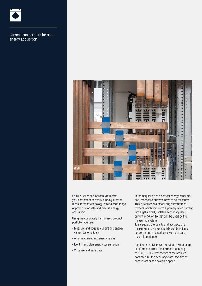
Current transformers for safe energy acquisition
In the acquisition of electrical energy consump-tion, respective currents have to be measured. This is realised via measuring current trans-formers which transform a primary rated current into a galvanically isolated secondary rated current of 5A or 1A that can be used by the measuring system.To safeguard the quality and accuracy of a measurement, an appropriate combination of converter and measuring device is of para-mount importance.
Camille Bauer Metrawatt provides a wide range of different current transformers according to IEC 61869-2 irrespective of the required nominal size, the accuracy class, the size of conductors or the available space.
Camille Bauer and Gossen Metrawatt, your competent partners in heavy current measurement technology, offer a wide range of products for safe and precise energy acquisition.
Using the completely harmonised product portfolio, you can:
• Measure and acquire current and energy values systematically
• Analyse current and energy values
• Identify and plan energy consumption
• Visualise and save data

Ideally suited to energy and current measuring devices
Compact design facilitates applications involving places hard to access and limited in space
Large selection of versions for new designs or subsequent integration into existing facilities
Different assembly options are available
Flexible use in circular conductors, copper bars, mounting rails or assembly plates
FLEXIBLE
Easy and time-saving assembly and installation
Easy and safe connection technology
Versatile assembly due to foot, rail and wall mounting
Free of maintenance
EASY
High measuring accuracy up to Class 0.2S
High safety due to galvanic isolation between measuring circuit and measuring device
High overload capacity
Compliance with IEC 61869-1 and IEC 61869-2
Robust break-proof plastic housing
Flame resistant and self-extinguishing according to UL94 V0
Primary bar mounting with insulating protection cap (touch-proof)
Touch and tamper protection of connections due to sealable covers or lockable plug terminals
SAFE
PAGE 4POWER SYSTEM MONITORING
CURRENT TRANSFORMERS
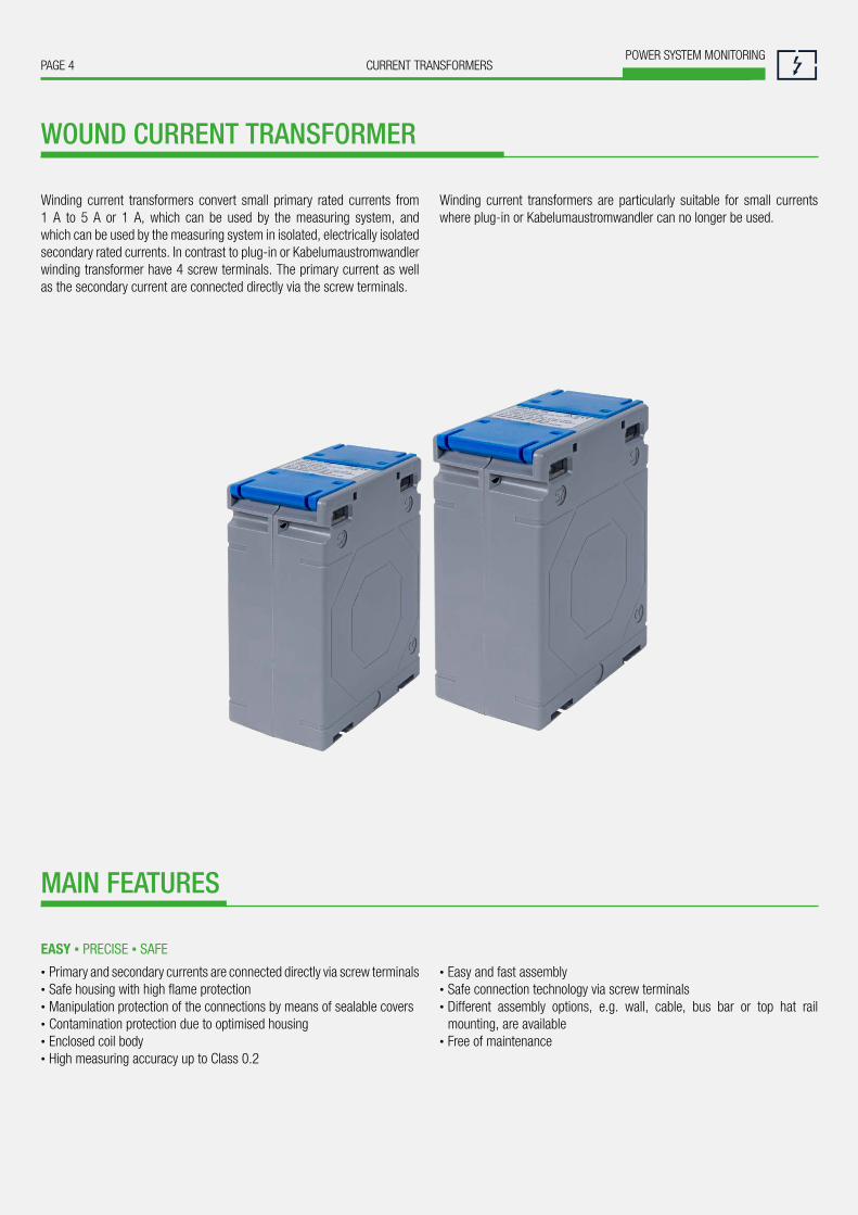
WOUND CURRENT TRANSFORMER
Winding current transformers convert small primary rated currents from 1 A to 5 A or 1 A, which can be used by the measuring system, and which can be used by the measuring system in isolated, electrically isolated secondary rated currents. In contrast to plug-in or Kabelumaustromwandler winding transformer have 4 screw terminals. The primary current as well as the secondary current are connected directly via the screw terminals.
Winding current transformers are particularly suitable for small currents where plug-in or Kabelumaustromwandler can no longer be used.
• Primary and secondary currents are connected directly via screw terminals • Safe housing with high flame protection • Manipulation protection of the connections by means of sealable covers • Contamination protection due to optimised housing • Enclosed coil body • High measuring accuracy up to Class 0.2
• Easy and fast assembly • Safe connection technology via screw terminals • Different assembly options, e.g. wall, cable, bus bar or top hat rail mounting, are available
• Free of maintenance
EASY ▪ PRECISE ▪ SAFE
MAIN FEATURES

PAGE 5CURRENT TRANSFORMERSPOWER SYSTEM MONITORING
safe ▪ flexible ▪ easy
TECHNICAL DATA
Type SIRAX CT100 SIRAX CT110
Width / height / depth 62 / 78 / 40 mm 74 / 98 / 45 mm
Primary current Ipr 1 A … 30 A 1 A … 60 A
Secondary current Isr 5 A or 1 A
Class of accuracy 0.2 0.5 0.2 0.5
Test voltage 3 kV; 50 Hz; 1 min
Nominal frequency 50 … 60 Hz
Rated insulation level Um 0.72 kV
Rated power Sr 1.0 VA 2.5 VA 1.5 VA 5 VA
Thermal short circuit current Ith 40 x INDynamic short circuit current Idyn 2.5 x IthInsulation class E (max. 120 °C)
Instrument security factor FS FS15 FS10 FS15 FS10
Housing material Polycarbonate
Flammability class UL94 V-0, self-extinguishing, not dripping, free of halogen
Ambient temperature -20 °C … +45 °C
Standard accepted IEC 61869-1; IEC 61869-2
Transformer type SIRAX CT100 SIRAX CT110
Accuracy class 0.2 0.5 0.2 0.5
Primary current Rated power / Instrument security factor (FS)
1 A 1 VA / FS15 2.5 VA / FS10 1.5 VA / FS15 5 VA / FS10
2.5 A 1 VA / FS15 2.5 VA / FS10 1.5 VA / FS15 5 VA / FS10
5 A 1 VA / FS15 2.5 VA / FS10 1.5 VA / FS15 5 VA / FS10
7.5 A 1 VA / FS15 2.5 VA / FS10 1.5 VA / FS15 5 VA / FS10
10 A 1 VA / FS15 2.5 VA / FS10 1.5 VA / FS15 5 VA / FS10
15 A 1 VA / FS15 2.5 VA / FS10 1.5 VA / FS15 5 VA / FS10
20 A 1 VA / FS15 2.5 VA / FS10 1.5 VA / FS15 5 VA / FS10
25 A 1 VA / FS15 2.5 VA / FS10 1.5 VA / FS15 5 VA / FS10
30 A 1 VA / FS15 2.5 VA / FS10 1.5 VA / FS15 5 VA / FS10
40 A – – 1.5 VA / FS15 5 VA / FS10
50 A – – 1.5 VA / FS15 5 VA / FS10
60 A – – 1.5 VA / FS15 5 VA / FS10

PAGE 6POWER SYSTEM MONITORING
CURRENT TRANSFORMERS
BUSHING-TYPE CURRENT TRANSFORMER
Bushing-type current transformers are used wherever high currents are to be acquired and processed. They are directly placed on the primary conductor (bus bar or conductor) through the opening. The secondary side (usually a measuring device, energy meter or display) is connected by front and rear connecting terminals.
Bushing-type current transformers constitute the most reliable, precise and cost-effective current transformer versions. However, the primary conductor must be disconnected for installation purposes. For this reason, they are more suitable for new facilities.
• Safe housing with high flame protection • Tampering protection due to sealable covers • Contamination protection due to optimised housing • Enclosed coil body • High measuring accuracy up to Class 0.2S • Large selection of nominal sizes and dimensions
• Easy and fast assembly • Safe connection technology via screw terminals • Suitable for circular conductors, copper rails, mounting rails • Different assembly options, e.g. wall, cable, bus bar or top hat rail mounting, are available
• Free of maintenance
PRECISE ▪ SAFE ▪ EASY
MAIN FEATURES
PAGE 7CURRENT TRANSFORMERSPOWER SYSTEM MONITORING
safe ▪ flexible ▪ easy
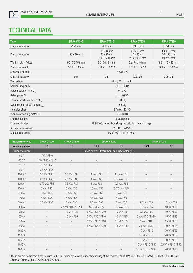
Type SIRAX CT200 SIRAX CT210 SIRAX CT220 SIRAX CT230
Circular conductor ∅ 21 mm ∅ 28 mm ∅ 30.5 mm ∅ 51 mm
Primary conductor 20 x 10 mm30 x 10 mm20 x 20 mm
2 x 15 x 10 mm
30 x 10 mm25 x 25 mm
2 x 20 x 10 mm
60 x 12 mm50 x 30 mm50 x 20 mm
Width / height / depth 50 / 70 / 51 mm 50 / 70 / 51 mm 62 / 78 / 40 mm 86 / 110 / 45 mm
Primary current Ipr 50 A … 300 A 100 A … 600 A 100 A … 800 A 300 A … 1600 A
Secondary current Isr 5 A or 1 A
Class of accuracy 0.5 0.5 0.2S; 0.5 0.2S; 0.5
Test voltage 4 kV; 50 Hz; 1 min
Nominal frequency 50 … 60 Hz
Rated insulation level Um 0.72 kV
Rated power Sr 1 … 20 VA
Thermal short circuit current Ith 60 x INDynamic short circuit current Idyn 2.5 x IthInsulation class E (max. 120 °C)
Instrument security factor FS FS5; FS10
Housing material Polycarbonate
Flammability class UL94 V-0, self-extinguishing, not dripping, free of halogen
Ambient temperature -20 °C … +45 °C
Standard accepted IEC 61869-1; IEC 61869-2
Transformer type SIRAX CT200 SIRAX CT210 SIRAX CT220 SIRAX CT230
Accuracy class 0.5 0.5 0.2S 0.5 0.2S 0.5
Primary current Rated power / Instrument security factor (FS)
50 A 1 VA / FS10 – – – – –
60 A * 1 VA / FS5 / FS10 – – – – –
75 A * 1.5 VA / FS5 – – – – –
80 A 2.5 VA / FS5 – – – – –
100 A * 2.5 VA / FS5 1.5 VA / FS5 1 VA / FS5 1.5 VA / FS5 – –
120 A * 2.5 VA / FS5 2.5 VA / FS5 1 VA / FS5 2.5 VA / FS5 – –
125 A * 3.75 VA / FS5 2.5 VA / FS5 1 VA / FS5 2.5 VA / FS5 – –
150 A * 5 VA / FS5 5 VA / FS5 1.5 VA / FS5 3.75 VA / FS5 – –
200 A 5 VA / FS5 5 VA / FS5 2.5 VA / FS5 5 VA / FS5 – –
250 A 5 VA / FS5 5 VA / FS5 2.5 VA / FS5 5 VA / FS5 – –
300 A * 7.5 VA / FS5 5 VA / FS5 2.5 VA / FS5 5 VA / FS5 1.5 VA / FS5 5 VA / FS5
400 A – 7.5 VA / FS5 / FS10 3.75 VA / FS5 7.5 VA / FS5 2.5 VA / FS5 10 VA / FS5
500 A – 10 VA / FS5 5 VA / FS5 / FS10 10 VA / FS5 2.5 VA / FS5 10 VA / FS5
600 A – 15 VA / FS5 5 VA / FS5 / FS10 15 VA / FS5 5 VA / FS5 / FS10 15 VA / FS5
750 A – – 5 VA / FS5 / FS10 15 VA / FS5 5 VA / FS10 15 VA / FS5
800 A – – 5 VA / FS5 / FS10 15 VA / FS5 7.5 VA / FS10 20 VA / FS5
1000 A – – – – 10 VA / FS10 20 VA / FS5
1200 A – – – – 10 VA / FS10 20 VA / FS5
1250 A – – – – 10 VA / FS10 20 VA / FS5
1500 A – – – – 10 VA / FS10 / FS5 20 VA / FS10 / FS5
1600 A – – – – 10 VA / FS10 / FS5 20 VA / FS5
TECHNICAL DATA
* These current transformers can be used in the 1A version for residual current monitoring of the devices SINEAX DM5000, AM1000, AM2000, AM3000, CENTRAX CU3000, CU5000 and LINAX PQ3000, PQ5000.

PAGE 8POWER SYSTEM MONITORING
CURRENT TRANSFORMERS
Due to their compact design and easy installation, split-core current transformers are particularly suited to applications involving places hard to access and limited in space. The separable cores also facilitate the installation on cables or bus bars. Wherever an interruption of the current path is problematic or a measuring device has to be retrofitted in an uncomplicated manner, split-core current transformers are the correct choice.
They transform primary rated currents into galvanically isolated secondary currents of 5 A or 1 A that can be used by the measuring system.The secondary side (usually a measuring device, display or control) is connected by terminals. The design ensures the safe assembly of the primary cable or bus bar in the current transformer which is confirmed by a clearly audible «clicking sound». An additional locking mechanism prevents accidental opening of the separable cores.
• Safe housing with high flame protection • Tampering protection due to sealable covers • Contamination protection due to closed housing • Separable coil body • Additional locking protection prevents accidental opening • Large selection of nominal sizes and dimensions
• Easy and fast assembly due to separable cores • Safe connection technology via screw terminals • Ideal for retrofitting in existing facilities without any interruption of the current supply
• Different assembly options, e.g. wall, cable, bus bar or top hat rail mounting, are available
FLEXIBLE ▪ SAFE ▪ EASY
SPLIT-CORE CURRENT TRANSFORMER
MAIN FEATURES

PAGE 9CURRENT TRANSFORMERSPOWER SYSTEM MONITORING
safe ▪ flexible ▪ easy
Type SIRAX CT300 SIRAX CT310 SIRAX CT320 SIRAX CT330
Internal dimensions 23 x 33 mm 55 x 85 mm 55 x 125 mm 85 x 172 mm
Width / height / depth 93 / 106 / 40 mm 125 / 158 / 40 mm 155 / 198 / 40 mm 195 / 245 / 40 mm
Primary current Ipr 100 A … 400 A 250 A … 2000 A 1600 A … 3000 A 2500 A … 5000 A
Secondary current Isr 5 A or 1 A
Class of accuracy 0.5; 1 0.5 0.5 0.5
Test voltage 4 kV; 50 Hz; 1 min
Nominal frequency 50 … 60 Hz
Rated insulation level Um 0.72 kV
Rated power Sr 1 … 20 VA
Thermal short circuit current Ith 60 x INDynamic short circuit current Idyn 2.5 x IthInsulation class E (max. 120 °C)
Instrument security factor FS FS10; FS15; FS30
Housing material Polycarbonate
Flammability class UL94 V-0, self-extinguishing, not dripping, free of halogen
Ambient temperature -20 °C … +45 °C
Standard accepted IEC 61869-1; IEC 61869-2
Transformer type SIRAX CT300 SIRAX CT310 SIRAX CT320 SIRAX CT330
Accuracy class 0.5 1 0.5 0.5 0.5
Primary current Rated power / Instrument security factor (FS)
100 A – 1.5 VA / FS10 – – –
150 A – 1.75 VA / FS10 – – –
200 A – 2.5 VA / FS10 – – –
250 A – 3.75 VA / FS10 1 VA / FS10 – –
300 A 2.5 VA / FS10 5 VA / FS10 2.5 VA / FS15 / FS10 – –
400 A 3.75 VA / FS10 6.25 VA / FS10 2.5 VA / FS10 – –
500 A – – 3.75 VA / FS10 – –
600 A – – 5 VA / FS10 – –
750 A – – 7.5 VA / FS10 – –
800 A – – 7.5 VA / FS10 – –
1000 A – – 10 VA / FS10 – –
1200 A – – 10 VA / FS10 – –
1250 A – – 10 VA / FS10 – –
1500 A – – 10 VA / FS10 – –
1600 A – – 10 VA / FS10 20 VA / FS10 –
2000 A – – 10 VA / FS10 20 VA / FS10 –
2500 A – – – 25 VA / FS10 25 VA / FS30
3000 A – – – 30 VA / FS10 30 VA / FS30
4000 A – – – – 30 VA / FS30
5000 A – – – – 30 VA / FS30
TECHNICAL DATA
PAGE 10POWER SYSTEM MONITORING
CURRENT TRANSFORMERS
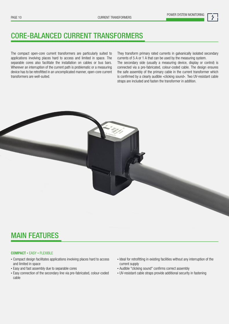
The compact open-core current transformers are particularly suited to applications involving places hard to access and limited in space. The separable cores also facilitate the installation on cables or bus bars. Wherever an interruption of the current path is problematic or a measuring device has to be retrofitted in an uncomplicated manner, open-core current transformers are well-suited.
They transform primary rated currents in galvanically isolated secondary currents of 5 A or 1 A that can be used by the measuring system.The secondary side (usually a measuring device, display or control) is connected via a pre-fabricated, colour-coded cable. The design ensures the safe assembly of the primary cable in the current transformer which is confirmed by a clearly audible «clicking sound». Two UV-resistant cable straps are included and fasten the transformer in addition.
• Compact design facilitates applications involving places hard to access and limited in space
• Easy and fast assembly due to separable cores • Easy connection of the secondary line via pre-fabricated, colour-coded cable
• Ideal for retrofitting in existing facilities without any interruption of the current supply
• Audible "clicking sound" confirms correct assembly• UV-resistant cable straps provide additional security in fastening
CORE-BALANCED CURRENT TRANSFORMERS
MAIN FEATURES
COMPACT ▪ EASY ▪ FLEXIBLE

PAGE 11CURRENT TRANSFORMERSPOWER SYSTEM MONITORING
safe ▪ flexible ▪ easy
Type SC30 SC40-B SC40-C SC50-E SC50-L
Internal dimensions 18 x 21 mm 18 x 19 mm 28 x 27.5 mm 42 x 43 mm 42 x 85 mm
Circular conductor ∅ 18 mm ∅ 18 mm ∅ 28 mm ∅ 42 mm 2 x ∅ 42 mm
Width / height / depth 36 / 50 / 48 mm 49 / 67 / 57 mm 49 / 67 / 57 mm 66 / 97 / 66 mm 66 / 139 / 66 mm
Primary current Ipr 60 A … 250 A 100 A … 250 A 200 A … 500 A 250 A … 1000 A
Secondary current Isr 1 A 5 A or 1 A
Cable length secondary line 3 m, 0.5 mm2 3 m, 0.5 mm2
0.5 m, 1.5 mm2
3 m, 0.5 mm2
0.5 m, 1.5 mm2
5 m, 0.5 mm2
3 m, 1.5 mm2
Class of accuracy 1; 3 0.5; 1 0.5; 1 0.5; 1 0.5; 1
Test voltage 3 kV; 50 Hz; 1 min
Nominal frequency 50 … 60 Hz
Rated insulation level Um 0.72 kV
Rated power Sr 0.2 … 1 VA
Thermal short circuit current Ith 60 x INDynamic short circuit current Icth 100 %
Insulation class E (max. 120 °C)
Housing material Polyamid (PA 6.6)
Flammability class UL94 V2, free of halogen
Ambient temperature -10 °C … +55 °C
Standard accepted IEC 61869-2
Transformer type SC30 SC40-B SC40-C SC50-E SC50-L
Secondary current 1 A 1 A 5A 1 A 5 A 1 A 5 A 1 A 5 A
Primary current Class Load Class Load Class Load Class Load Class Load Class Load Class Load Class Load Class Load
60 A 3 0.2 VA – – – – – – – – – – – – – – – –
75 A 3 0.2 VA – – – – – – – – – – – – – – – –
100 A 3 0.2 VA 1 0.2 VA – – – – – – – – – – – – – –
125 A 3 0.2 VA 1 0.2 VA – – – – – – – – – – – – – –
150 A 3 0.2 VA 1 0.2 VA 1 1 VA – – – – – – – – – – – –
200 A 1 0.2 VA 0.5 0.2 VA 1 1 VA 1 0.2 VA – – – – – – – – – –
250 A 1 0.2 VA 0.5 0.2 VA 0.5 1 VA 1 0.2 VA 1 1 VA 1 0.5 VA – – 1 0.5 VA – –
300 A – – – – – – 1 0.2 VA 1 1 VA 1 0.5 VA 1 0.5 VA 1 0.5 VA 1 0.5 VA
400 A – – – – – – 1 0.2 VA 1 1 VA 0.5 0.5 VA 1 0.5 VA 0.5 0.5 VA 1 0.5 VA
500 A – – – – – – 0.5 0.2 VA 1 1 VA 0.5 0.5 VA 1 0.5 VA 0.5 0.5 VA 1 0.5 VA
600 A – – – – – – – – – – 0.5 0.5 VA 0.5 0.5 VA 0.5 0.5 VA 0.5 0.5 VA
750 A – – – – – – – – – – 0.5 0.5 VA 0.5 0.5 VA 0.5 0.5 VA 0.5 0.5 VA
800 A – – – – – – – – – – 0.5 0.5 VA 0.5 0.5 VA 0.5 0.5 VA 0.5 0.5 VA
1000 A – – – – – – – – – – 0.5 0.5 VA 0.5 0.5 VA 0.5 0.5 VA 0.5 0.5 VA
TECHNICAL DATA

PAGE 12POWER SYSTEM MONITORING
CURRENT TRANSFORMERS
Bushing-type residual current transformers are used wherever very small currents are to be acquired and processed. They are directly placed on the primary conductor through the opening.
In conjunction with our device variants SINEAX DM5000, AMx000, CENTRAX CUx000 and LINAX PQx000, they can be used for residual and fault current monitoring of machines and plants.
• Highly sensitive current sensor for detecting smallest fault currents • Simple connection via 4-pole WAGO® spring-type terminal • High safety, thanks to integrated overvoltage protection • Flexible use due to a large frequency range • Easy and quick mounting
• Safe housing with high flame protection • Enclosed coil body
BUSHING-TYPE RESIDUAL CURRENT TRANSFORMER
MAIN FEATURES
EASY ▪ FLEXIBLE ▪ SAVE
PAGE 13CURRENT TRANSFORMERSPOWER SYSTEM MONITORING
safe ▪ flexible ▪ easy
TECHNICAL DATA
Type DACT-20 DACT-35 DACT-60 DACT-120
Primary conductor opening ∅ 20 mm ∅ 35 mm ∅ 60 mm ∅ 120 mm
Width / Height / Depth 82 / 63 / 30 mm 104.5 / 86.5 / 30 mm 135 / 117 / 37 mm 210 / 191.5 / 37 mm
Primary rated current Ipn 10 A
Secondary rated current Isn 0.0167 A
CT ratio 1:600
Rated burden 180 Ω / 50.2 mW
Accuracy class 1
Thermal nominal continuous current Icth 60 x Ipn / 1 s
Rct (75 °C) 5 ... 8 Ω
Rated voltage 800 V
Rated surge voltage 8 kV
Pollution degree 3
Operating frequency 30 Hz … 3 kHz
Rated insulation level Um 0.72 kV
Insulation class E
Secondary surge protection Suppressor diode P6KE68VA (integrated)
Insulation test voltage 3 kV; 50 Hz; 1 min
Housing protection class Housing: IP40; Terminal: IP20
Terminal connectionsSpring-loaded terminals, WAGO terminal 741-901; 4pole; 0,08 … 2.5 mm2
Stripping length of the connecting wires: 5 … 6 mm
Housing material Coycoloy C2100HF; RAL 3020
Flammability class UL94 V-0, self-extinguishing, non-dripping, halogen-free
Operating temperature -10 °C … +70 °C
Applied standards IEC 60664-1; IEC 60664-3
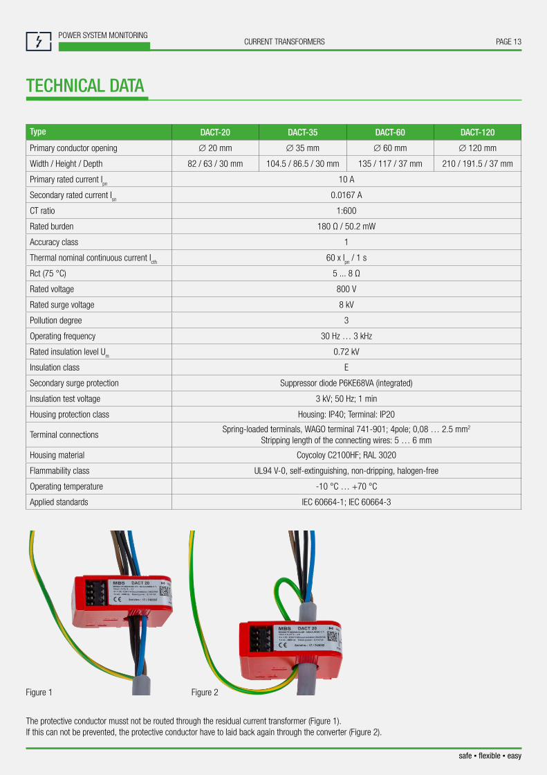
The protective conductor musst not be routed through the residual current transformer (Figure 1). If this can not be prevented, the protective conductor have to laid back again through the converter (Figure 2).
Figure 1 Figure 2
PAGE 14POWER SYSTEM MONITORING
CURRENT TRANSFORMERS
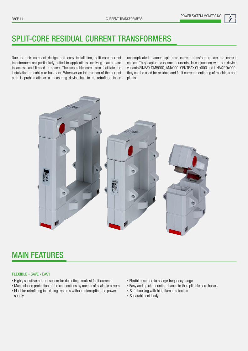
Due to their compact design and easy installation, split-core current transformers are particularly suited to applications involving places hard to access and limited in space. The separable cores also facilitate the installation on cables or bus bars. Wherever an interruption of the current path is problematic or a measuring device has to be retrofitted in an
uncomplicated manner, split-core current transformers are the correct choice. They capture very small currents. In conjunction with our device variants SINEAX DM5000, AMx000, CENTRAX CUx000 and LINAX PQx000, they can be used for residual and fault current monitoring of machines and plants.
• Highly sensitive current sensor for detecting smallest fault currents • Manipulation protection of the connections by means of sealable covers • Ideal for retrofitting in existing systems without interrupting the power supply
• Flexible use due to a large frequency range • Easy and quick mounting thanks to the splitable core halves • Safe housing with high flame protection • Separable coil body
SPLIT-CORE RESIDUAL CURRENT TRANSFORMERS
MAIN FEATURES
FLEXIBLE ▪ SAVE ▪ EASY

PAGE 15CURRENT TRANSFORMERSPOWER SYSTEM MONITORING
safe ▪ flexible ▪ easy
TECHNICAL DATA
Type KBU23D KBU58D KBU812D
Primary conductor opening 20 x 30 mm 50 x 80 mm 80 x 120 mm
Width / Height / Depth 93 / 106 / 34(58) mm 125 / 158 / 34(58) mm 155 / 198 / 34(58) mm
Primary rated current Ipn 10 A
Secondary rated current Isn 0.0167 A
Ratio 1:600
Rated burden 180 Ω
Accuracy class 1
Thermal nominal short circuit current ITH 60 x Icth / 1 s
Secondary rated apparent power 0.05 VA
Nominal frequency 50 Hz
Operating frequency 30 Hz ... 3 kHz
Rated insulation level Um 0.72 kV
Insulation class E
Insulation test voltage 3 kV; 50 Hz; 1 min
Housing protection class Housing: IP40; Terminal: IP20
Housing material Polycarbonate; RAL 7035; gray
Flammability class UL94 V-0, self-extinguishing, non-dripping, halogen-free
Operating temperature -5 °C … +45 °C
Applied standards IEC 61869-1; IEC 61869-2
PAGE 16POWER SYSTEM MONITORING
CURRENT TRANSFORMERS
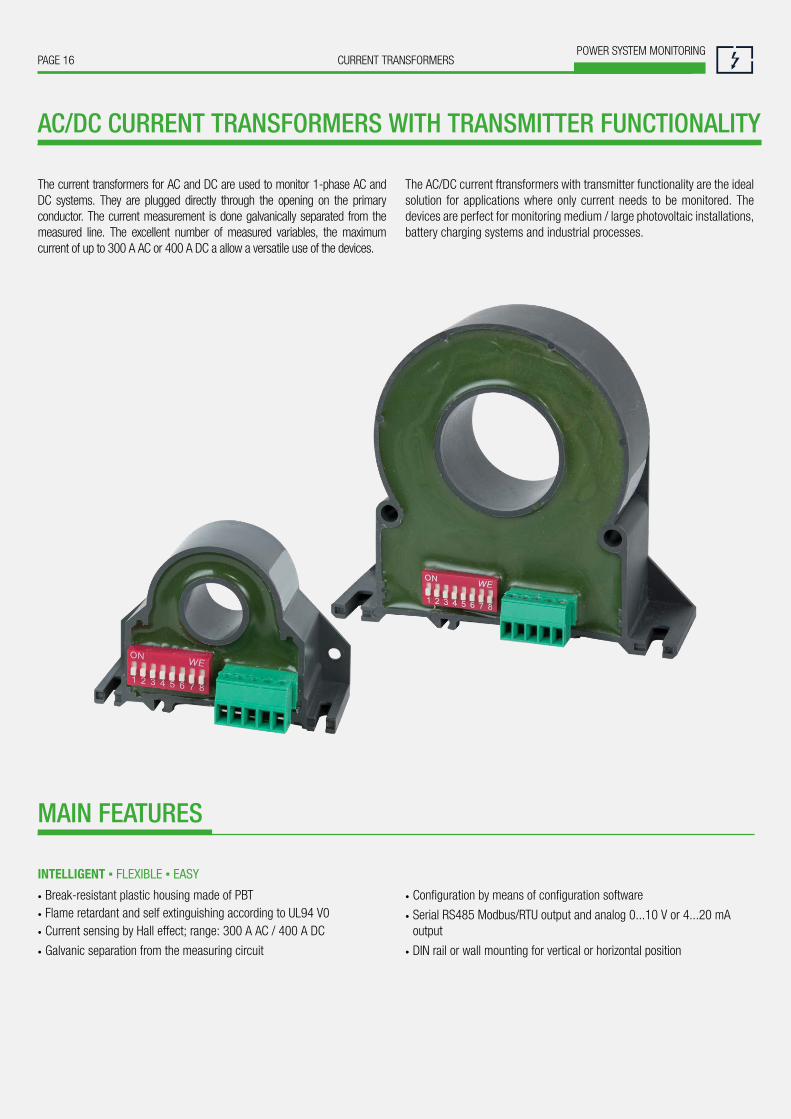
The current transformers for AC and DC are used to monitor 1-phase AC and DC systems. They are plugged directly through the opening on the primary conductor. The current measurement is done galvanically separated from the measured line. The excellent number of measured variables, the maximum current of up to 300 A AC or 400 A DC a allow a versatile use of the devices.
The AC/DC current ftransformers with transmitter functionality are the ideal solution for applications where only current needs to be monitored. The devices are perfect for monitoring medium / large photovoltaic installations, battery charging systems and industrial processes.
• Break-resistant plastic housing made of PBT • Flame retardant and self extinguishing according to UL94 V0 • Current sensing by Hall effect; range: 300 A AC / 400 A DC
• Galvanic separation from the measuring circuit
• Configuration by means of configuration software
• Serial RS485 Modbus/RTU output and analog 0...10 V or 4...20 mA output
• DIN rail or wall mounting for vertical or horizontal position
AC/DC CURRENT TRANSFORMERS WITH TRANSMITTER FUNCTIONALITY
MAIN FEATURES
INTELLIGENT ▪ FLEXIBLE ▪ EASY

PAGE 17CURRENT TRANSFORMERSPOWER SYSTEM MONITORING
safe ▪ flexible ▪ easy
TECHNICAL DATA
Type SIRAX BT7000 SIRAX BT7050 SIRAX BT7100 SIRAX BT7150
System type 1-phase AC/DC
Type of measure AC TRMS or DC
Dimensions 46.1 x 63 x 26.4 mm (without terminals) 89.1 x 99.25 x 28.5 mm (without terminals)
Installation form DIN rail mounting
Mounting position arbitrarily, vertically or horizontally
Max. cable diameter ∅ 14 mm ∅ 32 mm
Input range 50 A AC/DC 300 A AC/DC
Power supply 12 … 30 V DCpassive loop powered
11 … 30 V DC12 … 30 V DC
passive loop powered11 … 30 V DC
Absorption < 20 mA < 3.5 mA < 20 mA < 3.5 mA
Analog output 0 … 10 V DC 4 … 20 mA 0 … 10 V DC 4 … 20 mA
Digital output RS485 Modbus/RTU -- RS485 Modbus/RTU --
Band width DC or 20 … 2000 Hz
Accuracy 0.5 % F.S.
Resolution 12 bit
Temperature coefficient < 200 ppm/°C
Crest factor 2 1.4
Insulation test voltage 3 kV, 50 Hz, 1 min
Overload 2000 A (pulse); 300 A (continuos) 2000 A (pulse); 500 A (continuos)
Housing protection IP IP20
Connections Plug-in terminals 3.5 mm, 5 pol or 2 pol
Housing material PBT
Flammability UL94 V-0, self-extinguishing, non-dripping, halogen-free
Operating temperature -15 °C … +65 °C
Humidity 10 … 90 % (not condensing)
Programming Modbus RTU and software DIP switch Modbus RTU and software DIP switch

PAGE 18POWER SYSTEM MONITORING
CURRENT TRANSFORMERS
The power and energy meters for AC and DC are used to monitor 1-phase AC and DC systems up to a maximum current of up to 300 A AC and 400 A DC, and a maximum voltage of up to 800 V AC and 1000 V DC. They are plugged directly through the opening on the primary conductor. The current measurement is done galvanically separated from the measured line.
With the ability to measure currents with different frequency ranges, the AC/DC current transformers are the ideal solution for monitoring photovoltaic systems, battery charging systems, UPS systems, variable frequency drives and industrial processes.
• Break-resistant plastic housing made of PBT • Flame retardant and self extinguishing to UL94 V0 • Bidirectional energy measurement • Max. Input current up to 800 V AC / 1000 V DC • Max. Input voltage up to 300 V AC / 400 V DC
• Galvanic separation from the measuring circuit• Configuration by means of configuration software• Serial RS485 Modbus / RTU • DIN rail or wall mounting for vertical or horizontal position
CURRENT AND ENERGY METER FOR AC AND DC
MAIN FEATURES
INTELLIGENT ▪ FLEXIBLE ▪ EASY

PAGE 19CURRENT TRANSFORMERSPOWER SYSTEM MONITORING
safe ▪ flexible ▪ easy
TECHNICAL DATA
Type SIRAX BT7200 SIRAX BT7250 SIRAX BT7300 SIRAX BT7350
System type 1-phase AC/DC
Type of measure AC TRMS or DC
Dimensions 46.1 x 63 x 26.4 mm (without terminals) 89.1 x 99.25 x 28.5 mm (without terminals)
Installation form DIN rail mounting
Mounting position arbitrarily, vertically or horizontally
Max. cable diameter ∅ 14 mm ∅ 32 mm
Eingangsbereich Spannung 50 A AC/DC 300 A AC/DC
Eingangsbereich Strom 800 V AC / 1000 V DC 80 V AC / 100 V DC 800 V AC / 1000 V DC 80 V AC / 100 V DC
Ratio 1.0 standard (adaptable)
Hilfsenergie 9 … 30 V DC
Absorption < 1.3 W
Output range RS485 Modbus/RTU
Sampling rate 11kHz
Band width DC or 1 … 400 Hz
AccuracyVoltage, Current, Active power: < 0.5% F.S.
Frequency: ± 0.1 HzEnergy: ± 1%
Resolution 12 bit
Temperature coefficient < 200 ppm/°C
Crest factor 1.8 1.4
Input impedence 1 MΩ ±1 %
Insulation test voltage 3 kV;50 Hz, 1 min for voltage measurement / 4 kV; 50 Hz; 1 min for current measurement
Overvoltage categoryCATIII up to 600 VCATII up to 1000 V
CATIV up to 100 VCATIII up to 600 VCATII up to 1000 V
CATIV up to 100 V
Housing protection IP IP20
Connections Plug-in terminals 3.5 mm, 1x4 pol and 2x2 pol
Housing material PBT
Flammability UL94 V-0, self-extinguishing, non-dripping, halogen-free
Operating temperature -15 °C … +65 °C
Humidity 10 … 90 % (not condensing)
Programming Via DIP Switch, Modbus RTU and software

PAGE 20CURRENT TRANSFORMERSPOWER SYSTEM MONITORING
ROGOWSKI CURRENT SENSORS
Rogowski coils are air-core coils. The magnetic fi eld of the wrapped cur-rent-carrying conductors induces an alternating voltage in the coils which is proportional to the current. This is determined by integration of the voltage. For that an electronic circuit is required, which needs to be powered. The great advantage of Rogowski coils is the quick and easy installation, wi-
thout the need to disconnect current circuits. By means of switchable cur-rent measurement ranges almost any application may be covered without any variance. The principle also allows to measure fast current changes and harmonics a lot better than any conventional current transformer.
Integrator for measuring range option
• Quick and easy installation • Analysis of harmonics in power distribution • Measurement of dynamic currents
• Current measurement in melting processes • Test stands where test objects change often • Mobile measurements in power mains
MAIN FEATURES
EASY ▪ FLEXIBLE ▪ SAVE

PAGE 21CURRENT TRANSFORMERSPOWER SYSTEM MONITORING
DESCRIPTION ARTICLE NO.
APLUS: Rogowski current sensor, single phase, ACF3000_4/24, 2m 172 718
APLUS: Rogowski current sensor, single phase, ACF3000_30/24, 5m 173 790
ROGOWSKI CURRENT SENSORS
Typically the power supply of the Rogowski coils is done by means of bat-teries. But they have to be changed quite often and so this is not a solution which complies with industrial needs. To get around this, the multifunctional SINEAX CAM transformer is ready to provide this supply. There are different versions (3 V, 4.5 V, 6 V and 9 V) available to cover all the coils currently available on the market.
DESCRIPTION ARTICLE NO.
SINEAX CAM: Single phase, ACP FLEX 3000_5, 2m, Ø194mm, measurement ranges 30/300/3000 A, 9 V supply via CAM 169 426
SINEAX CAM: Three-phase, ACP FLEX 3003_5, 2m, Ø194mm, measurement ranges 30/300/3000 A, 9 V supply via CAM 169 434
The connection wires of these current sensors are equipped with endsplices and therefore can be directly connected to the screw terminalsof the CAM.
The connection wires of these current sensors are equipped with endsplices and therefore can be directly connected to the screw terminalsof the APLUS.
L1
L2
L3
N
easy ▪ flexible ▪ save

PAGE 22POWER SYSTEM MONITORING
CURRENT TRANSFORMERS
Current transformers supplement the measuring devices of Camille Bauer Metrawatt and Gossen Metrawatt in an ideal fashion. They transform high primary rated currents into smaller secondary rated currents for processing. These can then be acquired, visualised and further processed by measuring devices. Current transformers and measuring devices may be suitably combined. There is «no measuring device without a current transformer».
Camille Bauer Metrawatt and Gossen Metrawatt offer a broad product portfolio in the area of power system monitoring and energy management. The range includes products from basic transducers and multifunctional system components through to MID energy meters and energy data
management software. The measuring devices are suitable for front panel installation or top hat mounting and include extensive interface and communication options. We thus offer customers an optimum solution for data acquisition, visualising and analysis.
Our current transformers and measuring instruments may be used in almost any market segment or industry, e.g. energy generation and distribution, building engineering, manufacturing, hospital and medical engineering, computer centres and service providers.
EVERYTHING FROM ONE SOURCE
COMPLETE SOLUTIONS FOR POWER SYSTEM MEASUREMENT TECHNOLOGY
AM2000DM5SDM5000
Acqu
isiti
on
Data Management &Visualising
Measuring &Display
Sensor
cons
ulta
tion
& se
rvic
e
Visu
alis
ing
&An
alys
is
SMARTCOLLECT EMC
Current Transformer
MM1400 BM1200 AM1000
PAGE 23CURRENT TRANSFORMERSPOWER SYSTEM MONITORING
safe ▪ flexible ▪ easy
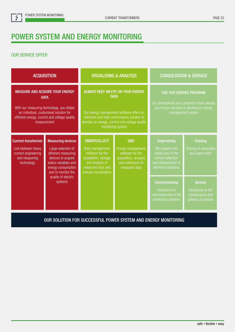
OUR SOLUTION FOR SUCCESSFUL POWER SYSTEM AND ENERGY MONITORING
ACQUISITION
MEASURE AND ACQUIRE YOUR ENERGY DATA
With our measuring technology, you obtain an individual, customised solution for
efficient energy, current and voltage quality measurement
Current transformer
Link between heavy current engineering
and measuring technology
Measuring devices
Large selection of different measuring devices to acquire
status variables and energy consumption and to monitor the quality of electric
systems
VISUALISING & ANALYSIS
ALWAYS KEEP AN EYE ON YOUR ENERGY DATA
Our energy management software offers an extensive and high-performance solution to
develop an energy, current and voltage quality monitoring system
SMARTCOLLECT
Data management software for the
acquisition, storage and analysis of
measured data and process visualization
EMC
Energy management software for the
acquisition, analysis and settlement of measured data
CONSULTATION & SERVICE
USE OUR SERVICE PROGRAM
Our professional and competent team assists you in your decision to develop an energy
management system
Engineering
We support and advise you in the correct selection
and development of technical solutions
Commissioning
Assistance in commissioning of the monitoring systems
Training
Training of associates and expert staff
Service
Assistance in the maintenance and
upkeep of systems
POWER SYSTEM AND ENERGY MONITORING
OUR SERVICE OFFER

Camille Bauer Metrawatt AGAargauerstrasse 7 ▪ 5610 Wohlen ▪ SwitzerlandTEL +41 56 618 21 11 ▪ FAX +41 56 618 21 21
www.camillebauer.com ▪ [email protected] Subj
ect t
o ch
ange
with
out n
otic
e ▪
SM
-104
4-00
0-01
-EN-
07.1
8