current distortion evaluation in traction 4q constant...
TRANSCRIPT

J. Electromagnetic Analysis & Applications, 2009, 3: 129-137 doi:10.4236/jemaa.2009.13021 Published Online September 2009 (www.SciRP.org/journal/jemaa)
Copyright © 2009 SciRes JEMAA
129
Current Distortion Evaluation in Traction 4Q Constant Switching Frequency Converters
M. BRENNA1, F. FOIADELLI1, M. ROSCIA2, D. ZANINELLI1
1The Politecnico di Milano–Department of Energy, Milano, Italy; 2Department of Tecnologie e Progettazione, Università di Bergamo, Bergamo, Italy. Email: {morris.brenna, federica.foiadelli, dario.zaninelli}@polimi.it, [email protected] Received April 14th, 2009; revised July 13th, accepted August 2nd, 2009.
ABSTRACT
The paper deals with the power quality analysis of interlaced four quadrant (4Q) converters with constant switching frequency. These are in fact the input stages of the locomotives and high speed trains supplied by 25 kV, 50 Hz and 15 kV, 16.7 Hz lines. Due to the high power needed for the trains circulation, the 4Q converter can absorb distorted cur-rents, whose harmonic content can affect the signaling systems and communication devices. The presence of more con-verters gives the opportunity, using dedicated commutation strategy, to interlace them in order to reduce the harmonic content in the absorbed current. In the paper a suitable model of more 4Q converters is developed. The control logic implemented in the model allows the evaluation of the harmonic contribution of both single converter and the interlaced configuration. The analysis is carried out through electromagnetic transient simulations.
Keywords: Four Quadrant (4Q) Converter, Interlacing, Traction Systems, Power Quality Analysis, Commutation Strategy
1. Introduction
The four quadrant converter (4Q) is the actual best choice to supply the DC voltage link from AC power contact line. A typology of distributed power high speed electric trains having as input stages more 4Q converters [1] has been considered.
The presence of more converters is necessary to guar-antee a good redundancy in case of failure and gives the opportunity, using dedicated control logics, to interlace them in order to reduce the harmonic content of the ab-sorbed current. The high power requested by the train for its acceleration in starting phase and for the auxiliary services needs high power converters that do not allow high switching frequencies. Consequently the absorbed current presents a high ripple value characterized by high harmonic current components that cannot be tolerated by the system. Indeed the track circuit used for signaling and communication for the traffic management and safety employs signal currents overlapped with the power ones. These currents can have low frequencies (50 Hz and 178 Hz) in the traditional signaling system, or they are in the audio frequencies range for the new European ERTMS/ETCS one. Therefore, the harmonics produced by the 4Q converter can disturb the communications of the track circuit, degrading the safety of the trains circu-
lation. On the other hand the 4Q converter has the main benefit to give a nearly sinusoidal line current in both directions of energy flow and the mitigation of reactive power drawn from the line. In fact the 4Q converter is based on the use of forced commutation switches (GTO, IGBT) and presents a sinusoidal current absorption in phase with the contact line voltage. Moreover, this con-verter is intrinsically bidirectional and then it can be used both for traction and regenerative braking phases.
The aim of this paper is an analysis of the current ab-sorbed by the high speed trains through a suitable model of more 4Q converters. Thanks to a control logic applied in this work, it is possible to interlace two or more con-verters in order to evaluate the harmonic contribution of both single converter and the interlaced configuration. The simulation results obtained with an electromagnetic analysis will be presented.
2. Mathematical Model of the 4Q Converter
The principle scheme reported in Figure 1 shows how the four-quadrant converter is structurally equal to a single phase voltage source inverter and employs the same switches used for the motor drives. This is an advantage

Current Distortion Evaluation in Traction 4Q Constant Switching Frequency Converters 130
because the various branches can have a modular con-struction [2]. The system includes: he transformer secondary side; four switches (GTO or IGBT), T1 ÷ T4; four freewheeling diodes D1 ÷ D4; a DC link with capacitive middle circuit C be-
tween the terminals AK and working at the im-posed voltage Vd=cost;
a second harmonic filter L2–C2 placed downstream the main bridge, tuned to a frequency f2=2·f1 dou-ble to the line one.
The system has two main purposes. The first one is the absorption from the contact line, at a voltage e1 and fre-quency f1, of a current having the fundamental harmonic i1 in phase with e1 and with low harmonic content, in order to respect the following conditions:
1
~1 distortion factorcos 1 power factor
(1)
The second purpose is the absorption from the line of a power with a mean value P1, pulsing at the frequency 2·f1 and the supply of the three-phase motor drive inverters connected to the dc link with a continuous power Pd.
In order to study the behaviour of this converter, the modelling process starts by a mathematical representation of the discrete operation modes of the converter. The discrete model describes each working mode through separate equations. Figure 2 shows a simplified repre-senttation of the two-level converter from which the discrete model is derived.
i1
e1 e2
T1
T2 T4
T3
D1
D2
D3
D4
M
K
N
A i
is
L2
C2
C Vd
+
-
Id
Figure 1. Principle scheme of a four-quadrant converter. e1=line voltage at a frequency f1; i1=line current
Figure 2. Equivalent circuit of a four-quadrant converter
In the equivalent circuit of Figure 2, the transformer secondary side is represented by: an ideal voltage generator (e2=e1/h, where h is the
transformer ratio); an inductance L, equivalent to the leakage trans-
former one; a resistances Rs mainly due to the switches; load resistances R0; DC link capacitance C.
Considering the state variables is and vc, the converter state equations are the following:
22 2 sin( )s c
diL R i v E t
20
C C
dtdv v
C idt R
(2)
where ω is the angular frequency. Rewriting these equa-tions in matricial format, it comes out:
2 2 2
0
10 s
1 1/0 0s
C C
i R iL Ed
v R vC dt
in( )t
(3)
or ExAxZ where x is the state vector and is its time derivative.
x
Taking into account that the converter is a two level type, there is another possible operation mode, described by the following matrix A:
0
1
1 1/sR
AR
(4)
Looking at the matrix A, it is possible to note that in these two operation modes the first element of the first row and the second one of the second row are the same. Therefore, the state equation can be rewritten to:
2
0
0 s
1/0 0sRL E
x xRC
in( )t
1
(5)
where depends from the operation mode and can as-sumes the value 1 or -1.
In this analysis, the switches resistance Rs has been ne-glected.
The transformer leakage reactance depends by the contact line frequency:
1 2X L f L (6)
and it causes a lagging phase shift of an angle ψ between the converter voltage 2V and the supply one 2E . Therefore the first harmonic component of voltages and current become:
2 2 1 2 2 1 2 2 12 sin , 2 sin , 2 sini I t e E t v V t (
where the rms value of the AC voltage v2 is related to th
7)
e DC one Vd through a proportional coefficient:
Copyright © 2009 SciRes JEMAA

Current Distortion Evaluation in Traction 4Q Constant Switching Frequency Converters 131
(8)
The a
whe
DC link voltage of the single-phase converter has significant ripple component at twice the supply fre-
quency. In fact, as it is possible to note in Figure 1 and reported in [3], the current i given by the 4Q converter to the middle circuit is composed by two components:
sd iIi
re:
22 cos sind
k EI k I
X
(9)
is the direct component of the i(t) r
esponsible of the power absorption, and
2 1cos 2si k I t (10)
is an harmonic at the frequency f2=2·f1, with the follow-ing rms value:
2s
k II 2 tan
2 2
k E
X
(11)
The is(t) is absorbed by the dat
orption the input current
edicated filter L2–C2 tuned frequency f2 so that into the dc section that feeds the
motor inverter flows the only continuous component Id. Referring to the control, a smart modulation [4] has
been applied, where the input current follows a suitable sinusoidal reference in order to have a sinusoidal absorp-tion, as explained in the following paragraph.
3. Current Modulation
In order to have a sinusoidal absfollows a suitable sinusoidal reference.
The AC reference current is obtained by multiplying the AC line voltage with a suitable equivalent conduc-tance, in accordance with
1( ) ( )i t G v t (12)
where i is the phasor of the AC phase current and 1v is
the fun amental component of the AC contact line volt-age.
The AC voltage contains the fundamental componentan
d
d the component v" corresponding to the perturbations
present in the AC line (i.e. harmonics), the Park vector of the AC voltage being
''1( ) ( ) ( )v t v t v t (13)
Thus, the instantanve
eous real power, expressed as Park ctor, is given by
* *( ) Ra ap t v i 1
"2 *1 1
e Re
Re
v i G v v
G v G v v
(14)
where is the complex conjugated value of *1v 1v .
id th e sin-gle phase converter, the AC - DC power balance is given
by
Cons ering null power losses associated wi th
*1( ) Re DC DCp t v v v i (15)
and the DC current, neglectipressed with
ng the ripple, can be ex-
*1
1
ReDC
v vv i G
DCv
(16)
Considering the currena non-linear relation between the DC voltage v , the con-tro
ts flowing through the DC bus, dc
l variable G and the load current iload is obtained
*1Re
2DC
load
v vdvCi G
dt
" *211
Re
DC
loadDC DC
v
v vvi G G
v v
(17)
Since V1 can be considered constant, the (17) can be linearized as follows:
2 21 1
2DCd v V VC
dt V
2
" *1Re
DCDC DC
loadDC
G G v dV
v vwhere d i G
V
(18)
d represents a perturbation, due to the AC line distur-bances and the DC ripple.
Its transfer function is
For the DC voltage control, a proportional–integral (PI)controller has been chosen.
IP DC
kG k F s v
s
(19)
where F(s) is the transfer functiorequired for reducing the DC bus ripple.
puting the val-ue
n of the low pass filter
The Equations (18) and (19) constitute the closed loop of the DC voltage control that allows com
s of the PI parameters. In a first approximation the transfer function F(s) can be neglected, obtaining
2 2DC
sv s d
V VC G2 1 1
2 P IDC DC DC
s s k kV V V
(20)
The denominator, considering a damping ratio of 0.707, constrains the PI controller parameters to respect the fol-lowing relations:
21 1
aP
VG Gk
V
nd I P
DC DC DC
k kV V C
(21)
4. Model of the System
retical analysis above de-he system has been imple-
In order to validate the theoscribed, a suitable model of tmented in the EMTP-ATP dynamic simulation tool. The data employed for the modelization refer to a real High Speed Train operating in Italy in 25kV–50Hz lines. This
22 cos dV k V
E
Copyright © 2009 SciRes JEMAA
Current Distortion Evaluation in Traction 4Q Constant Switching Frequency Converters
Copyright © 2009 SciRes JEMAA
132
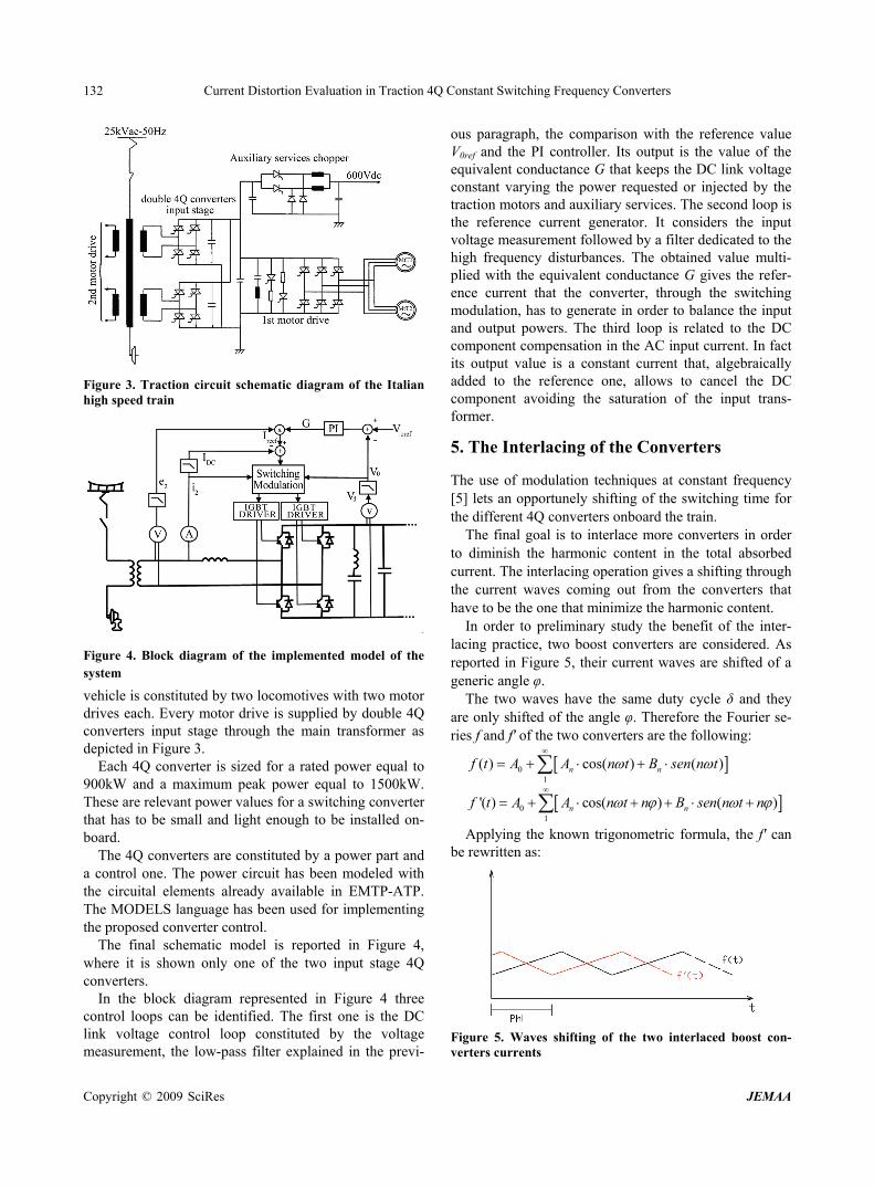
Figure 3. Traction circuit schematic diagram of the Italianhigh speed train
Figure 4. Block diagram of the implemented model of the system
ach. Every motor drive is supplied by double 4Q
um peak power equal to 1500kW. Th
l one. The power circuit has been modeled with th
the two input stage 4Q co
s can be identified. The first one is the DC lin
Interlacing of the Converters
requency [5] lets an opportunely shifting of the switching time for
l absorbed cu
s re
f the angle φ. Therefore the Fourier se-rie
vehicle is constituted by two locomotives with two motor drives econverters input stage through the main transformer as depicted in Figure 3.
Each 4Q converter is sized for a rated power equal to 900kW and a maxim
ese are relevant power values for a switching converter that has to be small and light enough to be installed on-board.
The 4Q converters are constituted by a power part and a contro
e circuital elements already available in EMTP-ATP. The MODELS language has been used for implementing the proposed converter control.
The final schematic model is reported in Figure 4, where it is shown only one of
nverters. In the block diagram represented in Figure 4 three
control loopk voltage control loop constituted by the voltage
measurement, the low-pass filter explained in the previ-
ous paragraph, the comparison with the reference value V0ref and the PI controller. Its output is the value of the equivalent conductance G that keeps the DC link voltage constant varying the power requested or injected by the traction motors and auxiliary services. The second loop is the reference current generator. It considers the input voltage measurement followed by a filter dedicated to the high frequency disturbances. The obtained value multi-plied with the equivalent conductance G gives the refer-ence current that the converter, through the switching modulation, has to generate in order to balance the input and output powers. The third loop is related to the DC component compensation in the AC input current. In fact its output value is a constant current that, algebraically added to the reference one, allows to cancel the DC component avoiding the saturation of the input trans-former.
5. The
The use of modulation techniques at constant f
the different 4Q converters onboard the train. The final goal is to interlace more converters in order
to diminish the harmonic content in the totarrent. The interlacing operation gives a shifting through
the current waves coming out from the converters that have to be the one that minimize the harmonic content.
In order to preliminary study the benefit of the inter-lacing practice, two boost converters are considered. A
ported in Figure 5, their current waves are shifted of a generic angle φ.
The two waves have the same duty cycle δ and they are only shifted o
s f and f' of the two converters are the following:
01
( ) cos( ) ( )n nf t A A n t B sen n t
01
)n n t n'( ) cos( ) (f t A A n t n B sen n
b
Applying the known trigonometric formula, the f' cae rewritten as:
n
Figure 5. Waves shifting of the two interlaced boost con-verters currents

Current Distortion Evaluation in Traction 4Q Constant Switching Frequency Converters 133
Figure 6. Behavior of the THD, varying the duty cycle δ and the shifting φ between the currents absorbed by the two boost
Applying the known trigonometric formula, the f' can
)
)
converters
be
here:
rewritten as:
w
'n cos( ) (
' cos( ) (n n
n n n
A A n B sen n
B B n A sen n
Considering that the current absorbed by the train is th
)
e sum of the currents absorbed by the two converters, the resulting function to consider for the THD calculus is given by the sum of the two functions, that means:
( ) ( ) '( )tf t f t f t
01
' '' cos( ) '' (n nA A n t B sen n t
with n'' 'n nA A A and n'' 'n nB B B .
his case the ab HD is define following: In t solute T d as
2
1nTHD Z (22)
with 2
it is possible to no e THD calculation the
first harmonic has been also considere referred to the sw
cycle δ, her
ha
THD is null for δ=0.5
he
2 2( '') ( '')n n nZ A B .
As te, in th
d , itching frequency, because all the ripple is an undesir-
able component. The THD so calculated is function of the shifting angle φ between the two waves and of the duty
e supposed the same for the two converters. In order to underline the THD dependence from the
parameters δ and φ, a simulation in Matlab environment
01
' cos( ) ' ( )n n
s been carried out. The (22) has been considered, varying the duty cycle between 0.1 and 0.9 and the shift-ing between 0 and 2π and supposing the current ripple amplitude equal to the 1% of the continuous component. The result is reported in Figure 6.
From Figure 6 it is possible to make some considera-tions. First of all, as expected, theand φ=π, because it is the only case in which the two tri-angle waves are symmetric and in opposite phase, there-fore all harmonics are cancelled.
From the optimal point, the THD initially grow fast, both varying δ and φ, underlining the fact that also small dissymmetry in the two converters switching diminish the advantages given by the interlacing. The optimal shifting φ is always equal to π and in this case the THD is always minor than the case of not interlaced converters (φ=0).
Finally, the THD is directly proportional to the ripple amplitude respect to the DC component, and for this t
'( )f t A A n t B sen n t
Copyright © 2009 SciRes JEMAA

Current Distortion Evaluation in Traction 4Q Constant Switching Frequency Converters 134
Figure 7. Shifting of the four switching frequencies
0 0.002 0.004 0.006 0.008 0.01 0.012 0.014 0.016 0.018 0.02-400
-300
-200
-100
0
100
200
300
400
500
t [s]
V [
V]
line voltage
Figure 8. Line voltage waveform measured on the secondary side of an auxiliary transformer
effective value
account the different typologies of inter-
mally running on
s coming out from the practical cases are operable locomotives and electro trains norhigher than the ones reported in Figure 6, considering the relevant current undulation due to the low switching fre-quencies.
Taking into
the railway lines, it is possible to note that after each input transformer there are 2 or 4 4Q converters. Each converter is supplied by a dedicated winding of the main transformer.
Copyright © 2009 SciRes JEMAA

Current Distortion Evaluation in Traction 4Q Constant Switching Frequency Converters 135
ch converter switching frequency has to be re
ain fr
g frequencies.
mutation instants are calculated st
Model for Harmonic Analysis and Simulation Results
the 4Q conve configu-
low short circuit level of the rail-w
due to the resonance phenomena alje
during a measurements survey
tude [%]
It comes out that, in order to have a good interlacing, the shift of ea
spectively equal to ½ or ¼ of the switching period. In this way the ripple of the current absorbed by the
transformer due to all the 4Q converters has the mequency equal to two or four times the switching one
with the advantages of a minor amplitude and easier fil-tration.
In Figure 7 is possible to note the shifting of the four switchin
Analyzing the smart modulation here applied, it is pos-sible to note as the com
arting from points on the reference current that have the same time distance. The interlacing can be easily ob-tained intercalating these time instants referred to the different converters.
6. 4Q Converters
In order to evaluate the harmonic contribution ofrters in single operation and in interlaced
ration, some numerical simulations are carried out, using ATP/EMTP program.
These converters are often supplied by a distorted in-put voltage, due to the
ay lines and a greater harmonic content allowed by the dedicated standards. A typical waveform measured on the secondary side of the transformer for auxiliary services ins reported in Figure 8.
The most significant components are reported in Table 1. This distortion is mainly
ong the line, also enhanced by the harmonic current in-cted by the trains. In order to have a correct operation of
the 4Q converters it is necessary to have a cleaner input voltage obtained installing LC filters in the input stage. Moreover, the greater components (>50th) are carefully
Table 1. Harmonic content of the line voltage recorded
Harmonics Order Frequency [Hz]
Harmonic Ampli-
1 50 100
3 150 7.14
15 750
1
25 1250 5.1
6.12
19 950 5.1
21 1050 2.76
23 1150 3.06
filtered to oid interferen signaling syIn this a alysis, each onverter has be
consideri the following characteristics: Hz;
equency: 500 Hz. e converter have been
, while the DC load with presents the current
ab
mines the input cur-re is
f the switches. This DC compo-ne
its
ach half period.
av ce with stem. n
ng 4Q c en studied
rated voltage of the contact line: 25 kV, 50 transformation ratio of the onboard transformer:
25/0.7 kV; DC link voltage: 1800 V; rated power: 900 kW; switching frThe power components of th
modeled with ideal switchescurrent generator. A negative value re
sorbed during the traction phase, while a positive one represents the regenerative braking.
In the controller are implemented two control loops. The first one gives the value of conductance G that
multiplied by the input voltage deternt reference. The value of the equivalent conductance G obtained through PI controller comparing the measure
of the DC link voltage with its reference in order to keep the DC voltage constant at its nominal value of 1800 V. The function of this controller is to guarantee the equiva-lence between the input power and the one absorbed by the load. In order to assure a uniform power absorption among the various converters, there is only one regulator for all the converters.
The second loop is necessary to cancel the DC com-ponent in the AC current that can be generated by the low switching frequency o
nts can be dangerous for the onboard transformer be-cause can saturate the magnetic core. Indeed this trans-former is not oversized due to the need to reduce its weight and volume. Therefore it is really sensible to the direct current component. Because the four 4Q converters are supplied by four independent transformer windings, it is necessary to adopt one of these regulators for each converter. In Figure 9 the current absorbed by one 4Q converter and its Fourier analysis are reported. It is pos-sible to note a high ten order components corresponding to the switching frequency, but also an appreciable third harmonic. This last one is due to the difficulty to follow up the sinusoidal reference having a so low switching frequency.
The interlacing of the four converters has really re-duced the harmonic content, as it is well represented in Figure 10, where the current absorbed at pantograph and
Fourier analysis are reported. In particular there are no more harmonics at the switching frequency, but there is still the third harmonic, due, as told before, to the low switching frequencies.
What told above is confirmed by Figure 11, where it is possible to note that there is a difficulty of the converter to switch at the end of e
Copyright © 2009 SciRes JEMAA

Current Distortion Evaluation in Traction 4Q Constant Switching Frequency Converters 136
0 5 10 15 20 25 300,0
0,2
0,4
0,6
0,8
1,0
harmonic order
Figure 9. Current absorbed by one 4Q converter and its Fourier analysis
cing in improving the current waveform, e out of service of one converter has been considered.
Th
es out again. In fact it is
e end of each ha
als with a power quality analysis regarding the modern interoperable high speed
ore four quadrant (4Q) converters.
In fact, in the
In order to better evaluate the contribution of the four converters interlath
is condition can occur during the train operation. The current absorbed at pantograph in this second case
with only three 4Q converters working and its Fourier analysis are reported in Figure 12.
It is possible to note the worst harmonic content re-spect to the previous case and, most of all, the contribu-tion of the switching frequency com
evident the presence of the ten order component. Re-garding the third harmonic, the situation is not changed, always due to the low switching frequency.
In Figure 13 is reported the shifting of the three switching frequencies and also in this case it is evident the difficulty of the converter to switch at th
lf period.
7. Conclusions
The paper dethe input stage of trains constituted by mIn fact, the use of the 4Q converter allows to overcome the limits imposed by traditional rectifier.
However, the high power needed for the train accelera-tion, in the order of 6000 kW per locomotive, does not allow to have high switching frequencies.
0 5 10 15 20 25 300,0
0,2
0,4
0,6
0,8
1,0
harmonic order Figure 10. Current at pantograph in case of four 4Q con-verters working and its Fourier analysis
Figure 11. Currents absorbed by all the four 4Q converter interlaced
quently the absorbed current presents a high rip le value not always tolerable by the system.
rrent at th
of the interlacing in improving the cur-re
recent realization they reach the maximum value of 500 Hz. Conse
pThe presence of more converters gives the opportunity,
using dedicated control logics, to interlace them in order to reduce the harmonic content of the absorbed cu
e pantograph. Computer simulations have been carried out using a
suitable model of more 4Q converters, for determining the contribution
nt waveform. First, the case of four interlaced 4Q converters has
Copyright © 2009 SciRes JEMAA

Current Distortion Evaluation in Traction 4Q Constant Switching Frequency Converters
Copyright © 2009 SciRes JEMAA
137
0 5 10 15 20 25 300,0
0,2
0,4
0,6
0,8
1,0
harmonic order
Figure 12. Current at pantograph in case of three 4Qverters working and its Fourier analysis
con-
Figure 13. Currents absorbed by three 4Q converterlaced
ed operation allows the reducing of the absorbed urrent ripple, since the equivalent switching frequen
erformances of the
REFERENCES
[1] G. W. Chang, en, “Modeling
ic systems for transportation,” (in
, F. Foiadelli, G. C. Lazaroiu, and D. Zaninelli,
Carmeli, F. Castelli Dezza, and G. Superti Furga,
urga,
Zaninelli, “Harmonic disturbances in
ics due to
asso, R. Lamedica, R. Manigrasso, G. Sani, G.
chi, F. Foiadelli, and D. Zaninelli, “Developments
Allan, B. Mellitt, and J. Taufiq, “A power
inter- Superti Furga, and E. Tironi, “Reference power network for the harmonic propagation analysis,” European Trans-actions on Electrical Power Engineering ETEP, Vol. 2, 1992.
[10] G. Burbeen analyzed. In particular the analysis shows that the nterlacc cy is of power quality studies in electric transportation system,”
Electrical Power Quality and Utilisation, Journal, Vol. 6, No. 2, 2005.
[11] S. Burdett, J.
four times the single converter one. However the low harmonic components, such as the third one, cannot be canceled by this solution, therefore they have to be fil-tered by traditional LC passive filters.
The second case analyzed regards a condition that can occur during the train operation such as the out of service of one converter. In this situation the p
fact
train are guarantee by the other three converters, even if it is not possible to completely cancel the harmonic com-ponent at the switching frequency.
H.-W. Lin, and S.-K. Chcharacteristics of harmonic currents generated by high-speed railway traction drive converters,” Transac-tions on Power Delivery, IEEE, Vol. 19, No. 2, pp. 766–773, April 2004.
[2] F. Perticaroli, “ElectrItalian), Casa Editrice Ambrosiana, Milano (Italy), Janu-ary 2001.
[3] M. Brenna“Four quadrant converter analysis for high speed trains,” 12th International Conference on Harmonics and Quality of Power–ICHQP’06, Cascais, Portugal, 1–6 October 2006.
[4] M. S. “Smart modulation: A new approach to power converter control,” EPE’01, Graz, Austria, 27–29 Aug. 2001.
[5] M. S. Carmeli, F. Castelli Dezza, and G. Superti F“Constant frequency current modulation algorithm based on linkage flux,” PESC’03, Power Electronics Specialists Conference, Acapulco, Mexico, 15–19 June 2003.
[6] F. Foiadelli, G. C. Lazaroiu, and D. Zaninelli, “Probabil-istic method for harmonic analysis in railway system,” 2005 IEEE PES General Meeting, San Francisco (USA), 12–17 June 2004.
[7] P. Pinato and D. electric traction system overhead lines,” IEEE X Interna-tional Conference on Harmonics and Quality of Power, Rio De Janeiro (Brasil), 6–9 October 2002.
[8] W. Runge, “Control of line harmonfour-quadrant-converter in AC tractive stock by means of filter and transformer,” in Proc. EPE’97, pp. 3.459–3.464, 1997.
[9] A. Cap
or and harmonic comparison of AC railway power electronic traction converter circuits,” Fifth European Conference on Power Electronics and Applications, pp. 235–240, 13–16 Sep. 1993.