culshaw, b. (2004) optical fibre sensors - applications and … · 2017-11-06 · (effectively a...
TRANSCRIPT

Culshaw, B. (2004) Optical fibre sensors - applications and potential. In:
7th International Conference on Optoelectronics, Fiber Optics and
Photonics, 2004-12-08 - 2004-12-11. ,
This version is available at https://strathprints.strath.ac.uk/39078/
Strathprints is designed to allow users to access the research output of the University of
Strathclyde. Unless otherwise explicitly stated on the manuscript, Copyright © and Moral Rights
for the papers on this site are retained by the individual authors and/or other copyright owners.
Please check the manuscript for details of any other licences that may have been applied. You
may not engage in further distribution of the material for any profitmaking activities or any
commercial gain. You may freely distribute both the url (https://strathprints.strath.ac.uk/) and the
content of this paper for research or private study, educational, or not-for-profit purposes without
prior permission or charge.
Any correspondence concerning this service should be sent to the Strathprints administrator:
The Strathprints institutional repository (https://strathprints.strath.ac.uk) is a digital archive of University of Strathclyde research
outputs. It has been developed to disseminate open access research outputs, expose data about those outputs, and enable the
management and persistent access to Strathclyde's intellectual output.
OPTICAL fibre sensors � applications and potential
B. Culshaw Dept of Electronic and Electrical Engineering, University of Strathclyde,
Royal College Building, 204 George Street, Glasgow G1 1XW, UK
ABSTRACT
Fibre optic sensors have progressed considerably during the past few years and are now establishing their potential as very real contenders in the environmental, structural monitoring and industrial sensing areas. This paper will explore some examples of these emerging applications and analyse the benefits which optical fibre technology offers within these measurement sectors. We shall then continue to explore emerging prospects which offer new opportunities for future research and exploitation.
1. INTRODUCTION
Fibre optic sensors are beginning to be regarded as a maturing technology and indeed whilst there are a multiplicity of actual applications and numerous small companies are servicing this emerging field, there is also a continuing interest in research and development advancing and evaluating new ideas for novel measurements to address new needs. Fibre optic sensors have contributed to almost all the areas of measurement science as physical measurements, chemical measurements, biochemical monitoring, radiation measurements and electromagnetic field measurements. The total market volume appears to be around the 200 million dollars per annum mark with a projected increase of an order of magnitude within the next three to five years[1]. On a global scale this is still rather modest and, given the fragmentation of the applications, it leads inevitably into predominantly small specialist companies serving the original needs. This diversity of applications is a great fascination but also can seriously fragment and confuse any discussion of the present and the potential of fibre optic sensor technologies. Consequently for this paper we shall concentrate on what we believe is the dominant sector both in terms of research endeavour and market potential � namely the measurement of physical parameters, predominantly strain, temperature and magnetic fields. The aims of the paper are to introduce the optical modulation phenomena which underlie the measurement principles involved in these sensor technologies, to illustrate this with a discussion of a few example applications and thereafter to examine the prospects, future applications niches and research opportunities.
2. PHYSICAL SENSING - THE BASIC PRINCIPLES
Fibre sensor technologies can be split into two broad categories � extrinsic and intrinsic (figure 1). In extrinsic sensors the measurand interacts with a region separated from the fibre optic feed and return paths. In the intrinsic sensor the fibre itself transduces the measurand into an optical signal. Most physical sensors � and all the examples which we shall consider here � rely on intrinsic interactions[2].
Figure 1: Fibre optic sensors: Basic intrinsic and extrinsic architectures

If we examine the intrinsic processes we find again that there two basic classes of interactions (figure 2). In linear processes (elastic scattering) the spectral content of the input light is identical to that of the output light with the observation that the side bands corresponding to the modulation are added. In non linear (in-elastic) processes the spectral domain of the optical signal is shifted. Both of these basic approaches are utilised extensively in physical parameter sensing.
Figure 2: Fibre optic sensors: Interfacing the measurand to linear and non-linear optical phenomena
The dominant linear process through which a physical parameter is modulated onto optical carrier within a fibre optic guide is that of changing the optical delay. The delay comprises a combination of the physical length of the fibre and its refractive index (indeed it is the product of the two). Any modulation introduced via external measurand then operates on this product. Consequently both changes in refractive index and changes in physical length must be considered. The details of this process have been presented by many authors and in summary the optical delay changes by approximately 1 part per million per microstrain of longitudinal strain and ten parts per million per degree C change in temperature. The delay also changes in response to pressure (of the order of 1 part per million per bar). Additionally birefringent changes in delay may be introduced through asymmetric mechanical forces through which one state of polarisation may be affected differently from the other. This secondary affect has certainly been observed and has been put to good use in for example acoustic wave front and vibration monitoring systems. However the operating mechanisms through which the birefringence modulation occurs are only really understood for quasi-static forces and dynamic calibrated instruments using birefringence modulation have yet to be realised. Finally we should recognise that typical application requirements need of the order of one part per million strain sensitivity for quasi-static measurands in the presence of the temperature coefficient of ten parts per million. This implies that temperature should be known with an accuracy of the order of 0.1ûC or alternatively temperature correction mechanisms should be employed. For dynamic strain signals, sensitivities in the nano to pico strain region are desirable but temperature effects are readily isolated through filtering.
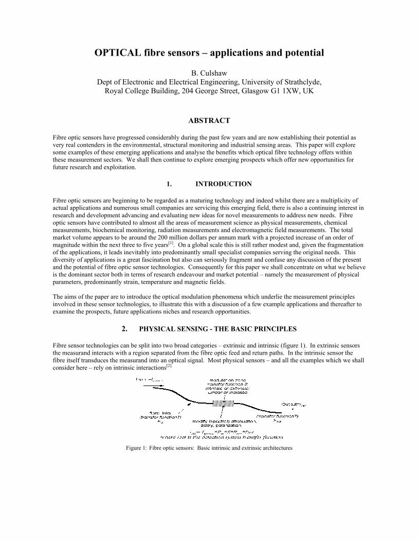
Non linear interactions are also important in physical parameter measurement and both Raman and Brillouin backscatter signals have been successfully exploited. Raman backscatter is typically used as a temperature measuring system and (figure 3) examining the spontaneous Raman scatter and measuring its intensity in equal bandwidths at frequencies symmetrical about the original optical excitation frequency gives a direct measure of temperature (see diagram). This mechanism has the enormous benefit of providing a strain insensitive thermal measurement.
In contrast, stimulated Brillouin is an excellent strain sensor (with temperature dependence as well). Some typical dependencies of the Brillouin backscatter frequency are shown in figure 4 for both temperature and strain variations. Again there is obvious cross talk and for reliable strain measurement temperature compensation is essential. The Brillouin scatter frequencies that are measured correspond to frequency offsets from the carrier introduced by phonon propagation in the fibre. The phonon propagation introduces in turn an effective backscattering diffraction grating (effectively a moving fibre Bragg grating), the period of which must be exactly half a wavelength of the optical signal in the fibre. Consequently Brillouin is effectively a measure of the acoustic velocity in the optical fibre.
The principal observations to draw from these very brief accounts of the basic principles are that physical measurands � notably temperature and strain � do affect the propagation characteristics of optical fibres and these effects can be used to
fibre links
����������������������������������
linear modulation
modulation zone
input
frequency f
output, at f
change intensity, delay, polarization, spectrum
modify (spectral) attenuation,
delay, polarization
����������������������������������
non-linear modulation
modulation zone
Raman, Brillouin, Kerr, Luminescence etc
output NOT at f
input
frequency f
monitor temperature and/or strain. Additionally most of the commonly used phenomena (optical delay and Raman and Brillouin scatter) have a substantial temperature coefficient. If these phenomena are to be used to measure strain then this temperature coefficient must be recognised and incorporated appropriately into the measurement protocol. Raman backscatter though does have the benefit that it can be configured to measure only temperature.
Figure 3: Inelastic scattering processes in optical fibres � Raman and Brillouin scatter illustrating spontaneous Raman and stimulated Brillouin with the former identifying the ratio metric technique for temperature measurement
Figure 4: Spontaneous Brillouin scatter for frequency off-sets measured at a wavelength of 1.55 µm for temperature and strain co-efficients
3. SYSTEM AND APPLICATION EXAMPLES
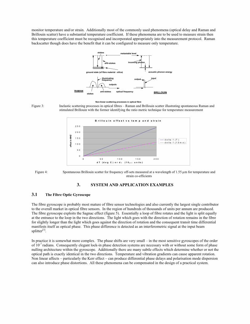
3.1 The Fibre Optic Gyroscope The fibre gyroscope is probably most mature of fibre sensor technologies and also currently the largest single contributor to the overall market in optical fibre sensors. In the region of hundreds of thousands of units per annum are produced. The fibre gyroscope exploits the Sagnac effect (figure 5). Essentially a loop of fibre rotates and the light is split equally at the entrance to the loop in the two directions. The light which goes with the direction of rotation remains in the fibre for slightly longer than the light which goes against the direction of rotation and the consequent transit time differential manifests itself as optical phase. This phase difference is detected as an interferometric signal at the input beam splitter[3].
In practice it is somewhat more complex. The phase shifts are very small � in the most sensitive gyroscopes of the order of 10-7 radians. Consequently elegant lock-in phase detection systems are necessary with or without some form of phase nulling architecture within the gyroscope. Additionally there are many subtle effects which determine whether or not the optical path is exactly identical in the two directions. Temperature and vibration gradients can cause apparent rotation. Non linear affects � particularly the Kerr effect � can produce differential phase delays and polarisation mode dispersion can also introduce phase distortions. All these phenomena can be compensated in the design of a practical system.
metastable level
incoming photon
stokes
anti-stokes
ground state (of fibre material - silica) acoustic phonon energy
illuminatingfrequency
outputs
stokesanti-stokes optical frequency
inputoutput
RAMANBRILLOUIN
Non-linear scattering processes in optical fibre
B r i l l o u i n o f f s e t v s t e m p a n d s t r a i n
0
5 0
1 0 0
1 5 0
2 0 0
2 5 0
0 5 0 1 0 0 1 5 0 2 0 0
d T ( d e g C ) o r d ε ( 1 0 µ ε u n i t s )
off
set
in M
HZ
d e lt a f ( T )
d e lt a f ( 1 0 m e )

Figure 5: The fibre optic gyroscope: Basic principles of the Sagnac effect and sample commercial gyroscope
The design process is though now complete and a variety of fibre gyroscopes with sensitivities ranging from a few to 10-3 degrees per hour to a few degrees per hour have been produced for a rich variety of applications. These applications range from navigational systems for sub sea vehicles to antenna pointing and stabilisation systems to missile guidance and heading correction in aircraft. Fibre loop lengths typically vary from a few tens of metres to several hundred metres and the fibre gyroscope is probably the only major market for significant lengths of single mode polarisation maintaining optical fibre wave guide[4]. It is important to appreciate why the fibre gyroscope is an attractive technology. First of all � and most important � it is cost competitive with rival approaches. However since the rival approaches are more well established, simply being cost competitive is insufficient. There must be performance benefits. The principal ones include a total lack of mechanical moving parts (no rotating precision bearings to wear out); the immunity of the scale factor of the gyroscope to high acceleration forces, the absence of any need for gimbals and mechanical correction systems (i.e. strapdown capabilities) and the inherent longterm reliability of all the components which comprise the fibre gyroscope and its mounting assemblies. The fibre gyroscope is an excellent example of fibre sensor technology action. It combines elegant optical principles with highly competent mechanical engineering and packaging to give a wide range of gyroscope performance parameters. Given the current state of competing gyroscope technologies, even with the emergence of MEMS, it seems likely that the fibre gyroscope will have a firm market presence for a considerable time to come.
Figure 6: The principles of the fibre Bragg grating
3.2 Fibre Bragg Gratings
The fibre gyroscope is configured to measure path difference between two counter rotating loops with very high precision. In contrast the fibre Bragg grating in effect measures the optical period of a structure written longitudinally into the optical fibre core. This period (figure 6) is ascertained by precisely measuring the wavelength which is reflected from the structure. The optical period depends upon both the physical distance between the periods in the structure and the refractive index in the way which was briefly outlined in section 2. When used as sensors the objective is to measure the value of the reflected wavelength or alternatively changes in this value referred back to a particular starting point in time. The fibre Bragg grating can be used to measure either temperature or strain (or indeed some combination of the two) and clearly, in order to achieve the microstrain resolution alluded to in the earlier discussion, wavelength
Polariser
Fibre loop
DC1 DC2
Architecture of the optical fibre gyroscope: DC is a directional coupler
rotation
������������
modulator
Polariser
Fibre loop
DC1 DC2
Architecture of the optical fibre gyroscope: DC is a directional coupler
rotation
������������
modulator

measurement precision of the order of picometers is essential for a typical central reflected wavelength of 1.5 µm. So this precision, whilst achievable, is difficult to repeat and requires constant recalibration to a referenced source(5). Fibre Bragg gratings have been extensively evaluated as strain measurement systems and there are numerous reasons why the Bragg grating is appealing as successor to the well-known electrical strain gauge. Of these perhaps the most persuasive is the ability (figure 7) to configure fibre Bragg gratings into networks comprising strings of elements with typically each operating through a different wavelength region or alternatively sufficiently separated in time for pulsed interrogation. Numerous such strings can be addressed through a single fibre optic switch � the number limited only by the necessary interrogation time for the strain gauge elements and this can be seconds or even minutes depending upon the particular circumstances. The great benefit is that the expensive wavelength monitoring unit can be shared amongst many tens of sensors thereby bringing the cost per point to a competitive value. The other major application advantage is that the fibre Bragg grating can be embedded into modern composite materials (figure 8) so that it is in intimate contact with the sample. This coupled with the fact that silica is elastic over a wide dynamic strain range (at least 1%) gives the technology particular benefits in the assessment of advanced materials such as glass and carbon fibre composites which are extensively used in the aerospace industry. Additionally extensive networks of Bragg gratings can be installed into a structure without the need for complex wiring harnesses and electrical power supplies. This very substantially simplifies both installation and maintenance in a practical environment.
Figure 7: Switched networks of fibre Bragg gratings
Figure 8: Embedding optical fibres in composite materials.
O p to e le c t r o n ic
in te r r o g a t io n
u n i t
S w itc h u n i t
F ib r e o p t ic l in k s
O p to e le c t r o n ic
in te r r o g a t io n
u n i t
B r a g g g r a t in g s e n s o r s :
e a c h a t d i f fe r e n t λ
S w itc h u n i t
F ib r e o p t ic l in k s
O p to e le c t r o n ic
in te r r o g a t io n
u n i t
S w itc h u n i t
F ib r e o p t ic l in k s
O p to e le c t r o n ic
in te r r o g a t io n
u n i t
B r a g g g r a t in g s e n s o r s :
e a c h a t d i f fe r e n t λ
S w itc h u n i t
F ib r e o p t ic l in k s

The strain and temperature coefficients of the reflected wavelength (again approximately 10ppm.°C-1 and 1ppm.µε-1) are intrinsically those which apply to the core of the fibre optic waveguide. The relatively large temperature coefficient yet again implies the need for temperature compensation and in many, possibly most, installations a temperature reference grating is build into the network to provide a thermal compensation signal. Fibre Bragg gratings have been installed and evaluated in a rich variety of structures predominantly as quasi static strain measurement devices. Some examples are shown in figure 9. Civil engineering, marine engineering and aerospace have perhaps attracted the greatest attention. In the civil engineering context it is usually the simple installation which dictates the use of Bragg grating sensors whilst in marine and aerospace the compatibility with highly technical material structures particularly carbon fibre is especially useful(6).
In carbon fibre composite panels
In the carbon masts of luxury yachts
Figure 9: Some examples of structures which have been instrumented with optical fibre Bragg gratings
as strain measuring devices.
The Bragg grating has also been the subject of extensive reliability studies of both the characteristics of the grating itself (which is affected compared to the original optical fibre by the photorefractive writing process) and of the interface between the fibre Bragg grating and the material have both been extensively studied and well characterised[7]. The principal remaining applications issue must address the compatibility of these sensor networks with real engineering requirements. The marine, aerospace or civil engineering community has yet to become fully accustomed to the availability of the extensive networks of measuring points which Bragg gratings afford. The rich characterisation which these networks of sensors allow on a structure needs to be assimilated into the usage and modelling philosophies which the applications communities utilise in damage assessment and usage monitoring activities. Whilst this utilisation is continually improving in the research community the actual user community is occasionally hesitant to learn more about its structure�s behaviour than legislation and reliability require. To date the Bragg grating has been part of a suite of instrumentation which has given comfort in procedures and processes during times of structural modifications or refurbishments. Certainly there is a role here and doubtless this role will expand as confidence in the basic technology increases and an appreciation of its application potential becomes more apparent.
3.3 Optical fibre interferometry
The Sagnac interferometer is probably the most widely used of optical fibre interferometers but other interferometric systems have been used to monitor physical parameters particularly both dynamic and static strain. The most usual architectures are optical fibre based Mach Zehnder or Michelson interferometers (figure 10) in which one arm of the interferometer is masked from the parameter to be measured and the other exposed. Phase modulation within the signal arm � essentially through the mechanisms outlined in section 2 � is detected using a suitably designed interferometer.

Usually the interferometer is biased to the quadrature point for maximum sensitivity using optical phase feed back on the reference arm, though occasionally other techniques such as phase ramping are used to assist in the detection process. Figure 10: Optical fibre interferometers: The Mach Zehnder and the Michelson configurations including the requirements for
the quadrature bias point.
The Mach Zehnder is the heart of most configurations of fibre optic hydrophone (figure 11). These are now produced as a commercial device and find applications both in sonar systems and seismic surveying the latter on and off shore. In common with the Bragg grating one of the great benefits of the Mach Zehnder hydrophone is that it can be configured into multiplexed architectures. Whilst these architectures are somewhat more complex than the Bragg grating equivalent they can, with the addition of optical amplification, operate with many 10s or even 100s of array elements[8]. In common with the Bragg grating this much simplifies interconnect between elements within an array so that the fibre array (see figure ? ) appears as little more than a cable with slight swellings (the hydrophones themselves) at appropriate points, the technology is particularly suited then to linear arrays. Sagnac interferometers have also been used as hydrophones.
Figure 11: Illustration of a fibre optic hydrophone system Clearly here rotation sensing is not the issue but introducing asymmetry into the disturbances on the fibre coil is most certainly important. The fibre optic Sagnac interferometer hydrophone is typically configured with one half of the hydrophone coil isolated from any potential disturbance.
The fibre optic Michelson has also found application � most notably as the SOFO [9]. In contrast to the hydrophone the SOFO is used for quasi-static strain/displacement monitoring and uses white light interferometry referenced against a mechanical displacement measurement to achieve accuracies and long term repeatabilities in displacement measurement of the order of a few microns. This can be realised with gauge lengths from a few 10s of centimetres up to 10 or more metres (figure 12). The SOFO is particularly suited to applications in civil engineering especially in concrete structures. Concrete is a highly inhomogeneous material so that localised strain measurements, as for example may be determined using strain gauges or Bragg gratings, are inadequate to generate a useful picture of structural performance and condition. The strain averaging capability afforded by SOFO is a much more reliable indicator. Several thousands SOFO sensors have now been installed, predominantly in Western Europe, and an extensive library of case study experience with these sensors is readily available.
F i g u r e 1 0
m a t c h e d e n d
m e a s u r a n d f i e l d
F i b r e s e n s i n g c o i l
i s o l a t e d c o i l
M a c h Z e h n d e r i n t e r f e r o m e t e r
p a t h d i f f e r e n c e
w a v e l e n g t h s
0 1
ou
tpu
t in
ten
sit
y
o u t p u t f r i n g e p a t t e r n
( d u a l b e a m )
p a t h d i f f e r e n c e
w a v e l e n g t h s
0 1
ou
tpu
t in
ten
sit
y
o u t p u t f r i n g e p a t t e r n
( d u a l b e a m )
O p e r a t i n g p o i n t s ( q u a d r a t u r e ) f o r m a x i m u m
s e n s i t i v i t y
Z e r o s e n s i t i v i t y p o i n t s
p a t h d i f f e r e n c e
w a v e l e n g t h s
0 1
ou
tpu
t in
ten
sit
y
o u t p u t f r i n g e p a t t e r n
( d u a l b e a m )
p a t h d i f f e r e n c e
w a v e l e n g t h s
0 1
ou
tpu
t in
ten
sit
y
o u t p u t f r i n g e p a t t e r n
( d u a l b e a m )
O p e r a t i n g p o i n t s ( q u a d r a t u r e ) f o r m a x i m u m
s e n s i t i v i t y
Z e r o s e n s i t i v i t y p o i n t s M i c h e l s o n i n t e r f e r o m e t e r
r e f l e c t o r s
M i c h e l s o n i n t e r f e r o m e t e r
r e f l e c t o r sr e f l e c t o r s
m e a s u r a n d f i e l d
r e f e r e n c e a r m
F i g u r e 1 1
( I l l u s t r a t i o n s f r o m E O
R e p o r t s S e p t e m b e r 2 0 0 0
: c o u r t e s y S P I E )

Figure 12: The principles of the SOFO white light Michelson interferometer for long gauge length strain measurements in civil engineering
3.4 Distributed physical sensing: Raman and brillouin scatter
Distributed sensing (figure 13) is an extremely powerful tool which is unique to optical fibre sensors. In distributed sensing the fibre itself forms the sensing element but the key lies in the interrogation technique � variations on the theme of optical fibre time domain reflectometry. This method enables a plot to be produced of the measurand of interest as a function of position along the length of the fibre. The measurand is averaged over an effective correlation length which is of the order of the pulse width (converted through the velocity of light in the fibre into a length) used in the OTDR. Typically resolutions of a metre or thereabouts can be expected over total ranges which can extend up to tens of kilometres.
Figure 13: Distributed sensor architectures using time domain reflectometry interrogation There have been numerous demonstrations of distributed sensing and some of these have matured into effective and competitive product. The most mature of these distributed sensing systems utilises spontaneous Raman backscatter as a distributed temperature probe. This technique, whilst in principle remarkably simple (measuring the ratio of the Stokes and anti-Stokes frequencies), can give simultaneously extremely useful thermal information. Temperature measurements capable
of resolving 1°C or better over convolution windows of the order of 1 metre in length can be relatively routinely achieved. Distributed Raman sensors now find application in long tunnels as fire alarms, in safety critical electrical equipment such as motor compartments and bearings in escalators in underground railway systems, long industrial process ovens for monitoring temperature gradients and profiles and numerous other specialised areas. The combination of hot-spot location and quantification with rapid response (a few seconds) and resolution to better than metres have made spontaneous Raman backscatter sensors a very powerful contender where temperature distributions or temperature alarms are required over large areas or long distances. Stimulated Brillouin scatter in contrast is, as we have already seen, both sensitive to temperature and strain effects. In practice stimulated Brillouin scatter has found most of its applications in strain sensing or more particularly in areas in which temperature variations are minimal (for instance sub-sea or underground). There are also some applications where anticipated strain changes can produce a far greater impact on the Brillouin scatter of set frequency signals than any anticipated temperature changes. Stimulated Brillouin scatter has been used for a considerable time to monitor optical fibre communication cables in underground ducts passing through regions subject to earth slippages through earthquake
s e n s o r a r r a y
s e n s o r s
o p t i c a l i n p u t
o u t p u t
P a s s i v e m u l t i p l e x i n g i n
n u m e r o u s a r c h i t e c t u r e s
( l a d d e r n e t w o r k h e r e )
s e n s o r a r r a y
s e n s o r s
o p t i c a l i n p u t
o u t p u t
s e n s o r a r r a y
s e n s o r s
o p t i c a l i n p u t
o u t p u t
s e n s o r a r r a y
s e n s o r s
o p t i c a l i n p u t
o u t p u t
P a s s i v e m u l t i p l e x i n g i n
n u m e r o u s a r c h i t e c t u r e s
( l a d d e r n e t w o r k h e r e )
m e a s u r a n d f i e l d
s i g n a lp r o c e s s i n g
d i s p l a y - m e a s u r a n da s f u n c t i o n o f p o s i t i o n
m o d u l a t e di n p u t l i g h t
D is t r i b u t e d s e n s in g
c o n c e p tm e a s u r a n d f i e l d
s i g n a lp r o c e s s i n g
d i s p l a y - m e a s u r a n da s f u n c t i o n o f p o s i t i o n
m o d u l a t e di n p u t l i g h t
m e a s u r a n d f i e l d
s i g n a lp r o c e s s i n g
d i s p l a y - m e a s u r a n da s f u n c t i o n o f p o s i t i o n
m o d u l a t e di n p u t l i g h t
m e a s u r a n d f i e l d
s i g n a lp r o c e s s i n g
d i s p l a y - m e a s u r a n da s f u n c t i o n o f p o s i t i o n
m o d u l a t e di n p u t l i g h t
D is t r i b u t e d s e n s in g
c o n c e p t

or subsidence. This technique has been most effect in providing advanced warning of, for example, imminent cable fracture. Stimulated Brillouin backscatter systems have also been applied sub-sea to monitoring high performance ropes and tethers and on land to monitoring oil pipelines. In all cases measuring potential disturbances over a long distance in very valuable installations has been the key theme in the use of Brillouin scatter. The monitoring equipment remains expensive (in the low 100s of 1,000s of US$) but its unique performance capability often over very long ranges is compelling when needed for security or integrity assessment. 3.5 Electro magnetic sensing
Voltage and current sensing particularly at high voltages (100s of kilovolts) is another niche in which fibre optic sensing has established very substantial benefits. The basic principles are shown in figure 14. Current sensing is almost invariably based on Faraday rotation usually in the optical fibre itself. Voltage sensing usually exploits the electro optic effect in a separate crystal coupled to the electric field which is to be measured. Both the electro optic effect and the Faraday effect are intrinsically extremely fast so that in principle measurements with bandwidths of gigahertz are feasible. In practice the bandwidth is limited by the interface between the electric field or magnetic field of interest and the optical fibre modulator[10].
Figure 14: Electric field and magnetic field sensing using optical fibres to determine voltage and current
waveforms in power transmission lines.
The established competing technology is however the current (or voltage) transformer. This is clearly a very traditional technique using mutual inductance between a primary and secondary coil as a coupling mechanism. Typically the primary coil is the current carrying conductor to be monitored. Consequently these sensing systems are inherently very limited in bandwidth � just to a few harmonics of the power line frequency. Additionally there is obviously an electrically conductive path involved in both the primary and secondary of such a transformer. The dielectric between the two windings must be extremely strong and insulation between the primary and secondary is a very considerable constraint in the design and implementation of transformer based current and voltage systems in the established network.
The optical fibre based system offers clear benefits in terms of both electrical bandwidth and inherent insulation between the measurement point and the monitoring point. There are many engineering issues to be resolved in the realisation of practical structures including the influence of vibration linearity in the output response, accuracy, sensitivity and repeatability. These have though now been addressed and several manufacturers now offer fibre optic instrumentation for power system measurement. The applications for fibre optic sensing in the power industry extend well beyond the monitoring of currents and voltages. Fibre optic sensors have found niches in looking for hot-spots in transformers, in temperature and strain measurement, in generators and turbines and in transformer oil contaminant assessment. All these sensor systems exploit the intrinsic electrical insulation features offered by the fibre optic medium with the attendant immunity to the high electric fields present in and around all these items of equipment and the frequent current and/or voltage transients.
������������������������
p o la r is e r
a n a ly s e r
E le c tr o (e le c t r ic f ie ld )
o r m a g n e t o ( c u r r e n t )
o p t ic c r y s t a l
I n p u t /o u t p u t le n s e sS e n s o r
h e a d
������������������������������������������������
p o la r is e r
a n a ly s e r
E le c tr o (e le c t r ic f ie ld )
o r m a g n e t o ( c u r r e n t )
o p t ic c r y s t a l
I n p u t /o u t p u t le n s e sS e n s o r
h e a d
���������������������������
C u r r e n t I
���������������
I n p u t
l ig h t
I n t e n s i t y
m o d u la t e d
o u t p u t
���������������������������
���������������������������
C u r r e n t I
������������������������������
I n p u t
l ig h t
I n t e n s i t y
m o d u la t e d
o u t p u t
��������������������
S in g le m o d e
o p t ic a l f ib r e
φ
I n p u t
l ig h t
I n p u t
p o la r is a t io nO u t p u t
p o la r is a t io n
φ = κ I
C u r r e n t I
����������������������������������������
S in g le m o d e
o p t ic a l f ib r e
φ
I n p u t
l ig h t
I n p u t
p o la r is a t io nO u t p u t
p o la r is a t io n
φ = κ I
C u r r e n t I

3.6 Application examples: some observations
The preceding sections have given some indication of the wide diversity of applications which physical sensors utilising fibre optic technology have settled into over the past few years. The applications are all very much niche oriented and all settle into relatively modest individual market sectors. Even the fibre gyroscope � the largest single technology � is available in tens of different variations depending on the application requirement.
4. PHYSICAL SENSORS USING OPTICAL FIBRES:
SOME THOUGHTS FOR THE FUTURE
Physical sensors based on fibre optic concepts have already found numerous specialised niche applications of which we have seen a number of examples in this paper. Future research and development could focus on several emerging areas. The photonic crystal fibre (figure 15) offers a mechanical as well as optical flexibility in design � though obviously at a cost in terms of technological complexity. There have been numerous suggestions that photonic crystal fibres could offer a new range of sensitivity and cross sensitivity options for mechanical sensing which have hitherto been precluded. These include, for example, increased radial compliance and the creation of sensitive geometries which have directional radial sensitivity. Additionally the exploitation of PCF at the photonic band gap edge could also enhance both strain and temperature sensitivity to external parameter changes.
Figure 15: The basic geometry of one of many types of photonic crystal fibres
Polymeric fibres have been little used in sensing though single mode polymer fibres are now available commercially. Polymers, whilst tolerant of large strains, tend to exhibit hysteresis and work hardening effects which have probably distracted from their potential as physical sensors. However to my knowledge no thorough evaluation of polymer fibres as sensors has yet been completed. Most certainly they will have very different temperature and strain co-efficients of phase delay and almost inevitably significantly different ratios of temperature and strain co-efficients. This could � perhaps � facilitate the combined temperature and strain measurements with good conditioning between the two. These measurements have been conducted using numerous geometries and several fibre materials throughout the years but have still proved elusive so strain and/or temperature isolated reference paths are often included in practical systems. There is also the mechanics of miniature systems. Optical fibres may facilitate measurements of mechanical properties of materials such as Young�s modulus, Poisson�s ratio and shear modulus with the capability to monitor and resolve variations within micrometer dimensions this could offer new insight into the design and realisation for MEMS systems and also into the properties of emerging structures fabricated in the micro and nano world. Intriguingly these small scale tools for mechanical measurements could readily be combined with high resolution chemical analysis using for example Raman and absorption spectroscopy.
Finally there is substantial opportunities for effective applications engineering. The relationship between the technologist and the user is complex and often frustrated by the need for mutual communication and understanding. There are undoubtedly opportunities for the currently available fibre optic sensor technology portfolio in industrial applications which have yet to be communicated between the two communities. However the very positive experience of the current well engineered systems within the user community is raising expanding awareness of the viability and applicability of fibre sensors stimulating optimism for the future. Patience though is an essential ingredient � sensor
Hollow core
photonic crystal
fibre
Open high field
central core: high
overlap integral
with gas in core
Hollow core
photonic crystal
fibre
Open high field
central core: high
overlap integral
with gas in core

technologies regardless of the market sector are slow to mature and require very careful implementation and testing since each is a little different from its neighbour. This diversity is however simultaneously a fascination and a challenge and is a major stimulus for a continuing interest in the discipline.
REFERENCES
1. D Krohn, �Fiber optic sensor consortium activities: Opportunities and barriers�, Proc. SPIE, Vol 5589, paper 6. Presented at Optics East, Philadelphia, October 2004.
2. B Culshaw and J P Dakin (eds.), Optical Fibre Sensors: Vol III Components and Subsystems and Vol IV
Applications Analysis and Future Trends, Artech House 1997 (Norwood Mass) 3. H.C. Lefèvre, The Optical Fibre Gyroscope, Artech House 1993 (Norwood, Mass). 4. E Udd (ed), Proc 15th International conference on Optical Fiber Sensors, Portland, Oregon, May 2002, pp1-22.
Proceedings published by IEEE/LEOS catalogue 02EX533. 5. A. Othonos and K. Kalli, Fiber Bragg Gratings, Artec House, Norwood, Mass 1999. 6. Proc. International Conference on Optical Fibre Sensors 14, 15, 16 (SPIE Vol 4185, FIEEE Cataolgue
02EX533, Academic Societies of Japan) and Proc EWOFS 2004 (SPIE vol 5502) are dominated by papers on the design and application of Fibre Bragg Gratings.
7. B Culshaw & Wolfgang Habel, �Fibre sensing: specifying components and systems�, Proc Symposium on
Optical Fibre Measurements 2004 (invited) pp 179-190, NIST Special Publication 1024, US Government Registry Office.
8. Michel Digonnet, B J Vakoc, C W Hodgson and G S Kino, �Acoustic fiber sensor arrays� (invited). Proc
EWOFS-04, pp.39-50 (SPIE vol., 5502) Santander, Spain, June 2004. 9. D Inaudi, �Testing performance and reliability of fiber optic sensing system for long term monitoring�, Proc.
EWOFS 04, p.552-555. 10. K Bohnart, P Gatus, H Brandle & A Khan, �Fibre optic current and voltage sensors for high voltage
substantions�, (invited). Proc. OFS(16), Nara, Japan, Oct 2003, pp. 752-755, Academic Societies of Japan, Tokyo 113-8622.