ct-gb-2008...ct-gb-2008 founded in 1969, ortea spa is now a leading manufacturer of voltage...
TRANSCRIPT

CT-GB-2008
Founded in 1969, ORTEA SpA is now a leading manufacturer of voltage stabilisers, magnetic components and electrical equipment. Such position has been reached thanks to the sound professional skills of its staff. Forty years in the business and ongoing technical research have made ORTEA a competitive and technologically up-to-date company. A close co-operation between design, production and marketing, allows for the needs of a constantly growing number of customers to be satisfied. In 1996 ORTEA joined the ICAR Group, which includes several European industrial units in the electro-technical field. A constant attention to market developments, pushes the company towards the improvement of established products and the design of new ones. Beside standard production, ORTEA is organised to be extremely flexible in developing and manufacturing special equipment according to user's specification, thanks to the experience gained by the Company over its many years of applied technological development. Such development now includes sophisticated computer hardware and software that enable the technical staff to draw up and to examine electrical and mechanical designs for each "custom product" on a quick and cost-effective basis. The belief that product quality and customer satisfaction are the core for a modern organisation, led to the implementation of an ISO 9001:2000 approved Quality System.
VOLTAGE STABILISERS 1

VOLTAGE STABILISERS 2

VOLTAGE STABILISERS Page
INTRODUCTION AND TECHNOLOGY 4
ELECTRODYNAMIC VOLTAGE STABILISERS WITH DIGITAL CONTROL 9
VEGA Single-phase voltage stabiliser from 0.3kVA up to 15kVA 11 ANTARES Single-phase voltage stabiliser from 7kVA up to 150kVA 14 ORION Three-phase voltage stabiliser from 2kVA up to 450kVA 17 SIRIUS Three-phase voltage stabiliser from 50kVA up to 4000kVA 25 TAURUS Three-phase voltage stabiliser from 800kVA up to 5000kVA 31
ELECTRODYNAMIC LINE CONDITIONERS WITH DIGITAL CONTROL
LYBRA Single-phase line conditioner from 0.3kVA up to 150kVA 35 ARIES Three-phase line conditioner from 2kVA up to 450kVA 39 DISCOVERY Three-phase line conditioner from 50kVA up to 4000kVA 43
STATIC VOLTAGE STABILISERS WITH DIGITAL CONTROL 47
GEMINI Single-phase voltage stabiliser from 0.5kVA up to 10kVA 48 AQUARIUS Three-phase voltage stabiliser from 3kVA up to 30kVA 49 ODYSSEY Three-phase digital network equalizer from 100kVA up to 1200kVA 50
DIAGRAMS 53
DIMENSIONS 57
ACCESSORIES 65
SPECIAL CONSTRUCTIONS
“CUSTOMISED” CONSTRUCTIONS 67
VOLTAGE REGULATING SYSTEMS 68
MAGNETIC PARTS
EXPOXY RESIN MV TRANSFORMERS 69
LV TRANSFORMERS 71
LV/MV REACTORS 75
VVOOLLTTAAGGEE SSTTAABBIILLIISSEERRSS
SSPPEECCIIAALL CCOONNSSTTRRUUCCTTIIOONNSS
MMAAGGNNEETTIICC PPAARRTTSS
rr r
This document is property of ORTEA SpA: it is compulsory to notify the Company Head Office and ask for authorisation before anyrelease or reproduction. ORTEA SpA shall not be held liable or responsible in any way whatsoever for unauthorised copies, alterations or additions made to the text or to the illustrations of this document. Any modification concerning Company logo, symbols of the certifications, nomenclature and official data is strictly p ohibited. For improvement purposes, the Company reserves the right to modify the p oducts described in this catalogue at any moment without p ior notice.
VOLTAGE STABILISERS 3
INTRODUCTION & TECHNOLOGY
IMPORTANCE OF VOLTAGE STABILISERSIMPORTANCE OF VOLTAGE STABILISERS
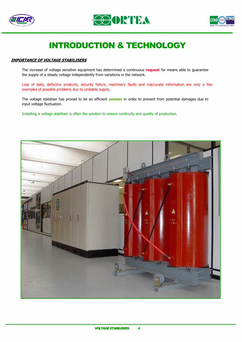
The increase of voltage sensitive equipment has determined a continuous request for means able to guarantee the supply of a steady voltage independently from variations in the network. Loss of data, defective products, security failure, machinery faults and inaccurate information are only a few examples of possible problems due to unstable supply.
The voltage stabiliser has proved to be an efficient answer in order to prevent from potential damages due to input voltage fluctuation.
Installing a voltage stabiliser is often the solution to ensure continuity and quality of production.
VOLTAGE STABILISERS 4
USE OF A VOLTAGE STABILISER USE OF A VOLTAGE STABILISER
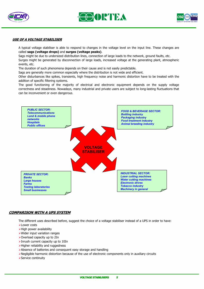
A typical voltage stabiliser is able to respond to changes in the voltage level on the input line. These changes are called sags (voltage drops) and surges (voltage peaks). Sags might be due to undersized distribution lines, connection of large loads to the network, ground faults, etc. Surges might be generated by disconnection of large loads, increased voltage at the generating plant, atmospheric events, etc. The duration of such phenomena depends on their cause and is not easily predictable. Sags are generally more common especially where the distribution is not wide and efficient. Other disturbances like spikes, transients, high frequency noise and harmonic distortion have to be treated with the addition of specific filtering systems. The good functioning of the majority of electrical and electronic equipment depends on the supply voltage correctness and steadiness. Nowadays, many industrial and private users are subject to long-lasting fluctuations that can be inconvenient or even dangerous.
PUBLIC SECTOR: Telecommunications Land & mobile phone networks Hospitals Public offices
PRIVATE SECTOR: Banks Large houses Farms Testing laboratories Small businesses
FOOD & BEVERAGE SECTOR: Bottling industry Packaging industry Food treatment industry Animal breeding industry
INDUSTRIAL SECTOR: Laser cutting machines Water cutting machines Electronic drives Tobacco industry Machinery in general
VOLTAGE STABILISER
COMPARISON WITH A UPS SYSTEMCOMPARISON WITH A UPS SYSTEM
The different uses described before, suggest the choice of a voltage stabiliser instead of a UPS in order to have:
Lower costs High power availability Wider input variation ranges Overload capacity up to 2In Inrush current capacity up to 10In Higher reliability and ruggedness Absence of batteries and consequent easy storage and handling Negligible harmonic distortion because of the use of electronic components only in auxiliary circuits Service continuity
VOLTAGE STABILISERS 5

CHOICE OF A VOLTAGE STABILISERCHOICE OF A VOLTAGE STABILISER
Generally speaking, a stabiliser can be chosen on the basis of a few elements: 1. NUMBER OF PHASES 2. RATED VOLTAGE 3. INPUT VARIATION RANGE 4. TYPE OF REGULATION 5. RATED POWER 6. INSTALLATION Once these six points have been established, any other optional request can be dealt with separately. 1. Number of phases
The stabiliser number of phases depends on the type of load: One 1-phase load: 1-phase stabiliser Combination of several 1-phase loads or 3-phase loads: 3-phase stabiliser or a 1-phase stabiliser on each load. 3-phase load: 3-phase stabiliser
2. Rated voltage
Always detect the nominal voltages that are supposed to be present at the input and at the output of the stabiliser. In case of 3-phase systems, provide with the line-to-line voltage value. Since there are different nominal voltages around the world, do not assume that YOUR nominal voltage is automatically known. The standard voltage stabiliser can operate with the following rated voltage:
RATED VOLTAGE 415 V ±15%
(353-415-477) 400V ±15%
(340-400-460)(323-380-437)
VOLTAGE STABILISER
VOLTAGE STABILISER
VOLTAGESTABILISER
by adjusting 415 V ±0.5%
the control card by adjusting
380 V ±0.5%
the control card standard setting
400 V ±0.5% 3. Input variation range
It’s key information for the choice and the design of the stabiliser. Establish the amplitude of the oscillation of the input voltage and always keep a safety margin on such percentage. The standard production can include stabilisers for symmetrical and asymmetrical input variation range. If the input voltage variation goes beyond the rated range, the difference between real and rated variation is transferred onto the output.
VOLTAGE STABILISERS 6

O U T P U T V O L T A G E W A V E F O R M
IN P U T V O L T A G E W A V E F O R M 4. Type of regulation
The three-phase voltage regulation can be performed in two different ways: independently on each phase. Used for 3-phase loads and 1-phase loads with until 100% unbalance and
unbalance input voltage rated. In this configuration the voltage stabiliser requires the neutral wire presence. averaged on the three phases. Used for 3-phase loads and 2-phase loads with 50% maximum unbalance and
balance input voltage rated. In this configuration the voltage stabiliser does not require the neutral wire presence.
1 -p h . lo a d
1 -p h . lo a d
1 -p h . lo a d
2 -p h . lo a d
3 -p h . lo a d
W 2O U T P U T
U 2 V 2 N
W 1
S T A B IL IS E R
IN P U TU 1 V 1 N
O U T P U TV 2U 2 W 2
3 -p h . lo a d
2 -p h . lo a d
S T A B IL IS E R
IN P U TV 1U 1 W 1
5. Rated power
Establish the power required to supply your load system and take into account an extra safety margin for possible future extensions. A voltage stabiliser power is expressed in kVA (kilovoltamperes), whilst load power is often given in kW (kilowatts). The link between these two measuring units is provided by the power factor (cosϕ):
ϕ=
coskW kVA
Remember the following: kVA = load voltage x load current (single-phase) kVA = x phase to phase load voltage x load current (three-phase) 3
If the power factor or the load power in kW cannot be easily established, measure the absorbed currents in order to allow for a correct design of the stabiliser. All the stabilisers are designed for the maximum input current.
VOLTAGE STABILISERS 7
6. Installation In order to provide with the best machine, it is recommended to inform about the installation condition. It is necessary to know:
IP protection degree Indoor or outdoor installation Installation site altitude and climatic properties Ambient temperature Possible environmental hazards such aggressive atmosphere, exposure to chemical components and so on.
AVAILABLE RANGEAVAILABLE RANGE ORTEA’s voltage stabiliser production covers an extensive range of standard types:
Single-phase electrodynamic line from 0.3 kVA to 150 kVA (VEGA, ANTARES and LYBRA) Three-phase electrodynamic line from 2 kVA to 5000 kVA (ORION, SIRIUS, TAURUS, ARIES and DISCOVERY) Single-phase static line from 0.5 kVA to 10 kVA (GEMINI) Three-phase static line from 3 kVA to 1000 kVA (AQUARIUS and ODYSSEY)
ADVANTAGESADVANTAGES Choosing an electromechanical voltage stabiliser means:
Smooth and reliable regulation from ±0.5% (electrodynamic voltage stabilisers) up to ±3%(static voltage stabilisers) output accuracy Admitted inrush current up to 10In Negligible introduction of harmonic distortion High efficiency High ratings
PERSONAL SAFETY PERSONAL SAFETY Access to the equipment can only be obtained by opening or dismantling the metal enclosure using appropriate tools; therefore, protection against direct contact inherently complies with IP21 class. Inside the equipment there are dangerous voltages. Access to the components for installation, setting, inspection and maintenance must be granted only to qualified personnel in charge of it. The stabiliser must not function without the earth connection. A circuit breaker should be installed upstream the equipment in accordance with the requirements of the International Standard IEC364 (CEI 64-8) “Electrical installations”. When manually handling is impossible, the stabilisers must be moved from the bottom exploiting the supporting pallet or from above through lifting lugs. The stabiliser must be used exclusively on the purpose for which it had been designed and built. Any other utilisation has to be considered as inappropriate and therefore dangerous. The Company will not be held liable for possible damages to people, animals and belongings due to incorrect use or installation.
VOLTAGE STABILISERS 8
ELECTRODYNAMIC STABILISERS WITH DIGITAL CONTROL
DESCRIPTION OF THE UNIT DESCRIPTION OF THE UNIT
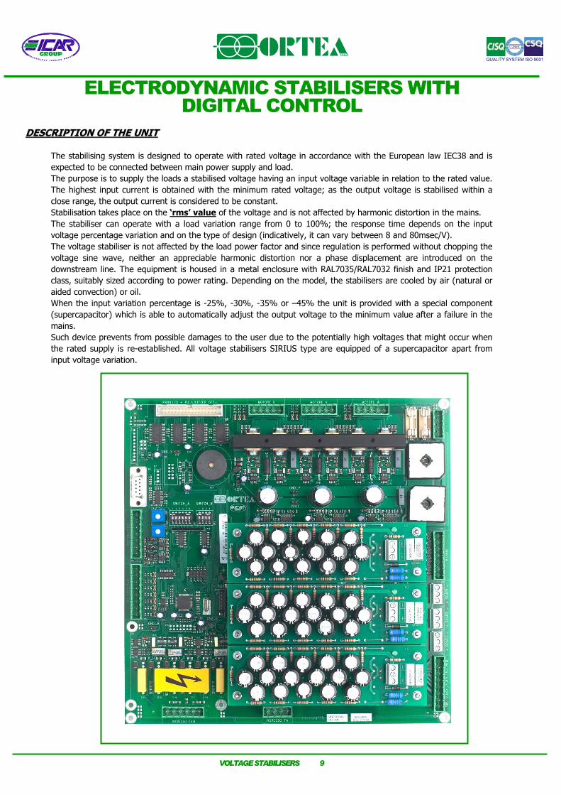
The stabilising system is designed to operate with rated voltage in accordance with the European law IEC38 and is expected to be connected between main power supply and load. The purpose is to supply the loads a stabilised voltage having an input voltage variable in relation to the rated value. The highest input current is obtained with the minimum rated voltage; as the output voltage is stabilised within a close range, the output current is considered to be constant. Stabilisation takes place on the ‘rms’ value of the voltage and is not affected by harmonic distortion in the mains. The stabiliser can operate with a load variation range from 0 to 100%; the response time depends on the input voltage percentage variation and on the type of design (indicatively, it can vary between 8 and 80msec/V). The voltage stabiliser is not affected by the load power factor and since regulation is performed without chopping the voltage sine wave, neither an appreciable harmonic distortion nor a phase displacement are introduced on the downstream line. The equipment is housed in a metal enclosure with RAL7035/RAL7032 finish and IP21 protection class, suitably sized according to power rating. Depending on the model, the stabilisers are cooled by air (natural or aided convection) or oil. When the input variation percentage is -25%, -30%, -35% or –45% the unit is provided with a special component (supercapacitor) which is able to automatically adjust the output voltage to the minimum value after a failure in the mains. Such device prevents from possible damages to the user due to the potentially high voltages that might occur when the rated supply is re-established. All voltage stabilisers SIRIUS type are equipped of a supercapacitor apart from input voltage variation.
VOLTAGE STABILISERS 9

MMAIN COMPONENTS AIN COMPONENTS The main components of the stabiliser are: 1. Buck/boost transformer
The buck/boost transformer is a standard dry-type transformer; the secondary winding is connected in series to the mains while the primary winding is supplied by the voltage regulator.
2. Voltage regulator
The voltage regulator consists of an autotransformer with continuously variable transformer ratio. The voltage intake varies depending on the position of the contacts; therefore the voltage supplied to the transformer primary winding also varies. Being the voltage across the regulator contacts (and consequently that on the secondary winding of the buck/boost transformer) either in phase or in opposition to the supply voltage, it is then added or subtracted to the supply voltage, thus compensating its variations.
3. AUXILIARY CIRCUIT WITH MICROPROCESSOR
The DSP (Digital Signal Processor) microprocessor-based control circuit (specifically designed for drives with totally digitalised signal) compares the output voltage value to the adjusted one. When the percentage variation is too high, the control drives the voltage regulator gearmotor. By doing so, the regulator rollers change their position thus varying the voltage drawn and supplied to the buck/boost transformer primary winding. All the above mentioned operation are automatic. The DSP microprocessor provides also for a SOFT-STOP system.
The voltage stabiliser can operate with input and output voltages different (380V/415V) from the rated voltage (400V). Such setting can be performed at the factory or at the Customer's premises by adjusting the dip-switches mounted on the electronic control card within the allowed range and according to the instructions described in the handbook. In the SIRIUS and TAURUS stabilisers, such setting can be performed by communicating directly with the microprocessor from a PC (through an RS232 interface). If the rated output voltage differs from the input voltage, a suitable step-up or step-down autotransformer should be installed in the equipment. However, the voltage stabiliser can work just as well after accepting that the range of input voltage variation is not symmetrical as long as it moves in positive or negative direction.
VOLTAGE STABILISERS 10
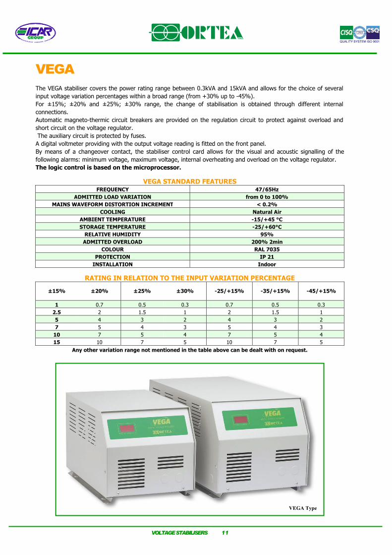
VEGA The VEGA stabiliser covers the power rating range between 0.3kVA and 15kVA and allows for the choice of several input voltage variation percentages within a broad range (from +30% up to -45%). For ±15%; ±20% and ±25%; ±30% range, the change of stabilisation is obtained through different internal connections. Automatic magneto-thermic circuit breakers are provided on the regulation circuit to protect against overload and short circuit on the voltage regulator. The auxiliary circuit is protected by fuses. A digital voltmeter providing with the output voltage reading is fitted on the front panel. By means of a changeover contact, the stabiliser control card allows for the visual and acoustic signalling of the following alarms: minimum voltage, maximum voltage, internal overheating and overload on the voltage regulator. The logic control is based on the microprocessor.
VEGA STANDARD FEATURES
RATING IN RELATION TO THE INPUT VARIATION PERCENTAGE
FREQUENCY 47/65Hz ADMITTED LOAD VARIATION from 0 to 100%
MAINS WAVEFORM DISTORTION INCREMENT < 0.2% COOLING Natural Air
AMBIENT TEMPERATURE -15/+45 °C STORAGE TEMPERATURE -25/+60°C
RELATIVE HUMIDITY 95%ADMITTED OVERLOAD 200% 2min
COLOUR RAL 7035 PROTECTION IP 21
INSTALLATION Indoor
±15% ±20% ±25% ±30% -25/+15% -35/+15% -45/+15%
1 0.7 0.5 0.3 0.7 0.5 0.32.5 2 1.5 1 2 1.5 1 5 4 3 2 4 3 2 7 5 4 3 5 4 3
10 7 5 4 7 5 4 15 10 7 5 10 7 5
Any other variation range not mentioned in the table above can be dealt with on request.
VEGA Type
VOLTAGE STABILISERS 11

VEGA ±20% ±15% AUTOMATIC SINGLE-PHASE VOLTAGE STABILISER
TYPE RATED POWER [kVA]
INPUT VOLTAGE
±20% ±15%
[V]
MAX INPUT
CURRENT [A]
OUTPUT VOLTAGE ±0.5%
[V]
RATED OUTPUT
CURRENT[A]
EFFICIENCY[%]
RESPONSE TIME
[ms/V] CABINET WEIGHT
[kg]
70-20 0.7 230 3.8 230 3 >94 12 12 16 100-15 1 230 5 230 4 >94 16 12 16 200-20 2 230 11 230 9 >96 12 12 23 250-15 2.5 230 12.5 230 11 >96 16 12 23 400-20 4 230 22 230 17.5 >97 12 12 28 500-15 5 230 25 230 22 >97 16 12 28 500-20 5 230 28 230 22 >98 12 13 41 700-15 7 230 35 230 31 >98 16 13 41 700-20 7 230 39 230 31 >98 12 13 47
1000-15 10 230 50 230 44 >98 16 13 47 1000-20 10 230 54 230 44 >98 12 13 55 1500-15 15 230 75 230 65 >98 16 13 55
VEGA ±30% ±25% AUTOMATIC SINGLE-PHASE VOLTAGE STABILISER
TYPE RATED POWER [kVA]
INPUT VOLTAGE
±30% ±25%
[V]
MAX INPUT
CURRENT [A]
OUTPUT VOLTAGE ±0.5%
[V]
RATED OUTPUT
CURRENT[A]
EFFICIENCY[%]
RESPONSE TIME
[ms/V] CABINET WEIGHT
[kg]
30-30 0.3 230 2 230 1.3 >96 8 12 16 50-25 0.5 230 3 230 2.2 >96 10 12 16
100-30 1 230 6.2 230 4 >97 8 12 23 150-25 1.5 230 9 230 6.5 >97 10 12 23 200-30 2 230 12.4 230 9 >98 8 12 28 300-25 3 230 18 230 13 >98 10 12 28 300-30 3 230 18.6 230 13.5 >98 8 13 41 400-25 4 230 23 230 17.5 >98 10 13 41 400-30 4 230 24.8 230 18 >98 8 13 47 500-25 5 230 29 230 22 >98 10 13 47 500-30 5 230 31 230 22 >98 8 13 55 700-25 7 230 41 230 31 >98 10 13 55
VEGA +15%/–25% AUTOMATIC SINGLE-PHASE VOLTAGE STABILISER
TYPE RATED POWER [kVA]
INPUT VOLTAGE
+15% -25% [V]
MAX INPUT
CURRENT [A]
OUTPUT VOLTAGE+/-0.5%
[V]
RATED OUTPUT
CURRENT[A]
EFFICIENCY[%]
RESPONSE TIME
[ms/V] CABINET
WEIGHT[kg]
70-15/25 0.7 230 4 230 3 >95 12 12 17 200-15/25 2 230 11 230 8 >96 12 12 24 400-15/25 4 230 23 230 17 >97 12 12 29 500-15/25 5 230 29 230 22 >97 12 13 42 700-15/25 7 230 40 230 30 >97 12 13 48
1000-15/25 10 230 58 230 43 >97 12 13 56
VOLTAGE STABILISERS 12

VEGA +15%/ –35% AUTOMATIC SINGLE-PHASE VOLTAGE STABILISER
TYPE RATED POWER [kVA]
INPUT VOLTAGE
+15% -35% [V]
MAX INPUT
CURRENT [A]
OUTPUT VOLTAGE+/-0.5%
[V]
RATED OUTPUT
CURRENT[A]
EFFICIENCY[%]
RESPONSE TIME
[ms/V] CABINET
WEIGHT[kg]
50-15/35 0.5 230 3 230 2 >95 10 12 17 150-15/35 1.5 230 10 230 6 >96 10 12 24 300-15/35 3 230 20 230 13 >97 10 12 29 400-15/35 4 230 27 230 17 >97 10 13 42 500-15/35 5 230 33 230 22 >97 10 13 48 700-15/35 7 230 47 230 30 >97 11 13 56
VEGA +15%/-45% AUTOMATIC SINGLE-PHASE VOLTAGE STABILISER
TYPE RATED POWER [kVA]
INPUT VOLTAGE
+15% -45% [V]
MAX INPUT
CURRENT [A]
OUTPUT VOLTAGE+/-0.5%
[V]
RATED OUTPUT
CURRENT[A]
EFFICIENCY[%]
RESPONSE TIME
[ms/V] CABINET
WEIGHT[kg]
30-15/45 0.3 230 2.3 230 1.3 >95 8 12 17 100-15/45 1 230 8 230 4 >96 8 12 24 200-15/45 2 230 16 230 8 >97 8 12 29 300-15/45 3 230 24 230 13 >97 8 13 42 400-15/45 4 230 31 230 17 >97 8 13 48 500-15/45 5 230 39 230 22 >97 9 13 56
ANTARES Type
The technical data in the above tables are subject to change by the Company either for internal reasons or because of a specific request from the Customer
Input output voltage 50Hz: 220/240V - Input output voltage 60Hz: 208/240V
VOLTAGE STABILISERS 13

VOLTAGE STABILISERS 14
ANTARES The ANTARES single-phase stabiliser covers the power rating range between 7kVA and 150kVA and allows for the choice of several input voltage variation percentages within a broad range (from +30% up to -45%). For ±15%; ±20% and ±25%; ±30% range, the change of stabilisation is obtained through different internal connections. Automatic circuit breakers are provided on the regulation circuit to protect against overload and short circuit on the voltage regulator. The auxiliary circuit is protected by fuses. A buzzer is activated whenever an overload condition occurs. The measuring instrumentation for the ANTARES stabilisers is installed on the cabinet door and consists of a multi-task digital network analyser. Such instrument is able to provide with information regarding the status of the line downstream the voltage stabiliser, such as phase voltage, current, power factor, cosϕ, active power, apparent power, reactive power, etc. By means of a changeover contact, the stabiliser control card allows for the acoustic signalling of the following alarms: minimum voltage, maximum voltage, internal overheating and overload on the voltage regulator. The logic control is based on the microprocessor.
ANTARES STANDARD FEATURES
FREQUENCY 47/65Hz ADMITTED LOAD VARIATION from 0 to 100%
MAINS WAVEFORM DISTORTION INCREMENT < 0.2% COOLING Aided air
AMBIENT TEMPERATURE -15/+45 °C STORAGE TEMPERATURE -25/+60°C
RELATIVE HUMIDITY 95%ADMITTED OVERLOAD 200% 2min
COLOUR RAL 7035 PROTECTION IP 21
INSTALLATION Indoor
RATING IN RELATION TO THE INPUT VARIATION PERCENTAGE
Any other variation range not mentioned in the table above can be dealt with on request.
±15% ±20% ±25% ±30% -25/+15% -35/+15% -45/+15%
20 15 10 7 15 10 7 25 20 15 10 20 15 1035 25 20 15 25 20 1545 35 25 20 35 25 2060 45 35 25 45 35 2575 60 45 35 60 45 35
100 75 60 45 75 60 45150 100 75 60 100 75 60