ct f january 1992 · 2011-05-14 · hazardous waste remedial actions program martin marietta energy...
TRANSCRIPT
RICKENBACKER AIR NATIONAL GUARD BASECOLUMBUS, OHIO
ADDENDUM TO THEPRE-CLOSURE SAMPLING REPORT
HAZARDOUS WASTE STORAGE AREA
AD-A252 559 DTICFINAL EL CT F
JUNi 6 1992DJANUARY 1992 sC t
I C3.u o~eI/
HARPSUPPORT CON 'f TR. OIF~icr.Oak Ridgc. Tennemec 37831!
M A NAGED BY MARnlN MARIETTA E.NE-RGY SYSTEMS, INc.For the U.S. DE PAT'MENT" OF E;NIERGY under contract DE-AC05-840R21!400

Report Document PagePlc reporting burden for this ildoiabon is estimated to average I hog per response, includng the time to review instructions, searcling esting data sources. gahwng andmaintaning the data needed, and compkiting and reviewing th coflecton of irdonlaton Send conerts regarding dis burden estimate ora y other aspect of this colection ofirtorrnion, including suggestions for reducing ths burden to Wastungton Senece Headquarters Servces Directorate for Intormatmon Operaions ad Reports. 1215 Jefferson CoosHi*Cwiev. Suit 1204. Arknoton. VA 22202-4302and toteOffice of Mnaenentand Budot. Paoework Reduction Proiect 0704&0188)Waslinaton. DC 205031. Agency Use Only (Leave Blwak) 2. Report Date 3. Report Type and Dates Covered
IJanuary 1992 Final Sampling Report4. Tide and Subttle 5. Funing Numbers
Rickenbacker Air National Guard Base, Columbus, OHAddendum to the Pre-closure Sampling ReportHazardous Waste Storage Area
6. Author(s)
N/A
7. Performng Orgaization Nane(s) and Address(es) 8. Perfoning Organization Reportnumber
Engineering - Science19101 Villaview Road - Suite 301Cleviand, Ohio 44119
9. Sponso1ngIMoN*orig Agency Name(s) and Address(es) 10. Sool Monkodng Agency
Hazardous Waste Remedial Action Program Report NumberOak Ridge TN
Air National Guard Readiness CenterAndrews Air Force Base, Maryland 20331
Ii. Supplemental Notes
12. Distribution/Availabllty Statement 12b. Distribution Code
Approved for public release; distribution is unlimited
13. Abstract (maxinum 200 words)
Additional investigations were required at the Hazardous Waste Storage Area at theRickenbacker Air National Guard Base. The purpose of the investigation was to determine thelateral and vertical extent of soil and ground water contamination contamination at the site.Additionally sufficient information was obtained in order to complete the addendum closure plan.The Hazardous Waste Storage Area will be closed in accordance with the Ohio EnvironmentalProtection Agency regulations once the final addendum closure plan is approved.
14. Subject Terms Hazardous Waste Storage Area, Rickenbacker Air National Guard 15. Nunber of PagesBase, Ohio Envirormental Protection Agency 67
16. Price Cod
17. Securlty Classification of IS. Security Classification of 19. Securty Classilcation of 20. UImtaton od AbstractReport this Page Abstract
Unclassified Unclassified Unclassified NoneNSN 740- -9G-56oM Stndrd Form 299 (Rev 2-90) Prescrbed by ANSI StdM 23M 0 299-0
I
ADDENDUM TO THEPRE-CLOSURE SAMPLING REPORT
RICKENBACKER AIR NATIONAL GUARD BASECOLUMBUS, OHIO
FINAL AceFsa± Yor
Jlw-, t i f Ir eat i et ,i- A L
JANUARY 1992 -
Avai lability Codesciand/or
Dist special
Submitted To:
NATIONAL GUARD BUREAUNGB/DEVR
ANDREWS AFB, MARYLAND
Submitted By:
HAZARDOUS WASTE REMEDIAL ACTIONS PROGRAMMARTIN MARIETTA ENERGY SYSTEMS, INC.
OAK RIDGE, TENNESSEE
--_ Prepared By:
ENGINEERING-SCIENCE19101 Villaview Road, Suite 301
Cleveland, Ohio 44119
* For the:
U.S. DEPARTMENT OF ENERGYUNDER CONTRACT NO. DE-AC05-8401U1400
92 6 12 0,3
0592EPCI94.30#WS 4.-

TABLE OF CONTENTS
Acronyms ill
1.0 EXECUTIVE SUMMARY 1-1
2.0 PURPOSE AND SCOPE 2-1
I 3.0 BACKGROUND 3-1
4.0 FIELD INVESTIGATION PROGRAM 4-14.1 Groundwater Screening 4-14.2 Monitoring Well Installation 4-34.3 Surface Soil Sampling 4-44.4 Groundwater Sampling 4-4
5.0 FIELD INVESTIGATION FINDINGS 5-15.1 Groundwater Results 5-15.2 Soil Results 5-15.3 Hydrogeology 5-6
6.0 CONCLUSIONS AND RECOMMENDATIONS 6-1
7.0 REFERENCE S 7-1
U LIST OF TABLES
Number Tik
1 VOCs in Groundwater Samples 5-22 SVOCs in Soil Samples 5-33 Metals Above Background in Soil Samples 5-54 Groundwater Elevations 5-8
LIST OF FIGURES
Number Titil
I 1 Location Map 2-22 Site Location Map 2-33 VOCs in Shallow Groundwater 4-24 Total SVOCs in Surface Soils 5-45 Groundwater Elevation Map 5-7
LIE OF APENDICES
_ Appendix A Momitoring Well Los/Construction DiagramsAppendix B Analytical Data Validation NotesAppendix C Validated Analytical Data
*192EII4J#WS .1

I ACRONYMS
BL Berkeley Laboratory
CLP Contract Laboratory Protocol
EPA Environmental Protection Agency
I ES Engineering-Science, Inc.
I HC Hydrocarbon
HWSA Hazardous Waste Storage Area
IRP Installation Restoration Program
MS Matrix Spike
MSD Matrix Spike Duplicate
MW Monitoring Well
PSH Phase-Separated Hydrocarbon
I PSP Pre-Closure Sampling Plan
QC Quality Control
SI Site Investigation
SS Soil Sample
SVOC Semi Volatile Organic Compound
US United States
UST Underground Storage Tank
VOC Volatile Organic Compound
I WO Work Order
IIII *92EC194-36#WS 4-U-

SECTION 1.0EXECUTIVE SUMMARY
This report addendum documents the activities and findings of field investigations
conducted at the Hazardous Waste Storage Area (HWSA) at Rickenbacker Air
National Guard Base (the Base) during October of 1991. The purpose of this
investigation is to determine the extent of chemical contamination in the surface
sediment, soil and groundwater at the HWSA.
Previous investigations at this site are described in a report by Engineering-Science,
Inc. titled "Pre-Closure Sampling Report, Hazardous Waste Storage Area" (draft,
October 1990).
Rickenbacker ANGB is located twelve miles southeast of Columbus, Ohio. The
facility has been in operation since the early 1940s in support of training and air-to-airI refueling missions.
The HWSA at the Base consists of Building 560 and the Drum Storage Area
southeast of the building. It has been under a Part A Permit for hazardous wastestorage since 1983. The facility was last used in September 1986. The Drum Storage
Area adjacent to Building 560 had been used to store liquid wastes such as spent
solvents, cleaning fluids, acids and paint strippers. There are four 25,000-gallon steel
underground storage tanks (USTs) adjacent to the HWSA. One tank is situated within
the area defined by the perimeter fence. The USTs have been in use for approximately40 years. Two tanks currently store de-icing fluid. JP-4 jet fuel, and recyclable oil were
historically stored in the other two tanks.
Activities conducted during the pre-closure sampling included surface soil sampling,
shallow and deep soil sampling by boring, installation of groundwater monitoring wells
and groundwater sampling.
All work conducted at the HWSA was done in accordance to the Pre-Closure
Sampling Plan (December 1989, Addended September 1991) with site activities being
complete in the Spring of 1990 and in October 1991.
I1M 9PC1t436W$ 1-1

The surficial (<30' below grade) unconsolidated materials are similar throughout
the Base and the HWSA. The uppermost ten feet is typically a brown silty clay, with
trace amounts of small pebbles. From ten to approximately fifteen feet is silty/sandy
clay. A saturated sand is encountered at approximately 15 feet. Water from this sandrises in wells to eight to ten feet below grade. This is underlain by a thin (<1') layer of
hard, dense gray clay over brown to gray sand and gravel. The hydraulic gradient is in ageneral southerly direction.
The investigation conducted in 1990 determined that the surface and shallow soil
within and adjacent to the HWSA are contaminated with metals, semi-volatile organiccompounds (SVOCs) and volatile organic compounds (VOCs). The extent andconcentration of contaminants generally decrease with depth. The exception to thatgeneralization is the contamination of the shallow aquifer with phase-separatedhydrocarbons, dissolved fuel components and halogenated VOCs with only trace
concentrations in the shallow soil. In 1991, additional investigations were conducted todetermine the extent of contamination.
The investigation conducted in 1991 defined the extent of the contaminants at thissite. Groundwater screening, soil boring and sampling, monitoring well installation,surface soil sampling and groundwater sampling were conducted during October of 1991
that assisted in defining the contaminant plume. The downgradient extent of thegroundwater is defined by monitoring wells (MW) 11 and 12 which are approximately120 feet downgradient from the southeastern corner of the HWSA.
Groundwater samples obtained from existing wells at the site confirmed existence ofVOCs previously detected in samples taken from these wells. Phase-separatedhydrocarbon (PSH) was apparent in MW1 and MW5 during the 1991 investigation("Determination of Phase-Separated Hydrocarbon Extent at the Hazardous Waste
Storage Area", draft, October 1990, ES). Well MW5 had previously exhibited the
existence of PSH.
Recovery of PSH has been ongoing at MW5. Limited amounts have been recoveredtotalling less than 55 gallons. The extent of PSH in the groundwater was explored using
the groundwater screening tool. The total extent of PSH is limited to the areaimmediately surrounding MW1 and MW5. The source or origin of the hydrocarbon isunclear.
0192EPI.M#WS 1.2

These data as well as all other data obtained at the HWSA will be incorporated into
a Closure Plan for the proposed closure of this permitted storage area. This ClosurePlan will be reviewed by the Ohio Environmental Protection Agency. It is anticipatedthat groundwater cleanup will be undertaken during the closure of this site.
9192EPCIIJ#W 1.3

SECTION 2.0
PURPOSE AND SCOPE
This addendum documents the activities and findings of the field investigations
conducted in October 1991 at the former Hazardous Waste Storage Area (HWSA),
building 560, at Rickenbacker ANGB, Ohio (Figures 1 and 2). These investigationswere conducted in accordance with the Pre-Closure Sampling Plan (PSP) dated
December 1989 and the Addendum #1 to the PSP dated September 1991. The data
collected during this investigation will be appended to the existing database for this site.Reporting of data from the original investigation was completed in the "Pre-ClosureSampling Report, Hazardous Waste Storage Area", draft, October 1990 by Engineering-Science (ES). All data obtained from this site will be used for the completion of aClosure Plan for this HWSA.
The additional sampling described in this addendum was conducted to fill data gapsexisting after the original pre-closure sampling report. Specifically, these data gaps are:
The anomalously high concentrations of semi-volatile organic compounds(SVOCs) found at the surface soils of the westernmost corner of the HWSA.
* The extent of VOCs previously detected in the groundwater. The findings of thisinvestigation define the extent of the contaminants from this HWSA.
1M2EPC4~WS 2.1

OHIO RICKENBACKERAIR NATIONAL GUARD BASE
ALAW I U
Mfg e aware 37 ire allAWhite ksh
Sulphur/ -., Stratf ord 35 r
ellpol t 14 14 unb
S'. Yotts 315 Lewis 11m .10 lienCtr. Hoove
dinAny 11 3 Res.wow 23 Cents.
N aw CAVERNS Village "'657ow Hill
ilifornia Powell Wes, 0 Get6 7 ille A.32. isN Central ...... rGrab-o *ng to.n 7 College ille ocrxal,
N St. NEW.2
tin 62 Albany M037 Sr. MEN.U M US.'lliard . I H e1- 14 it 8summ .......
7M ....... .. 4kNKLIN Sla. utVille
irkers- 10 H e 0113 Re n Idsbueg mvmx. Jl villew-4
40 115 ... ....79ferson, rj tic ey(
La e,L ..... ........U anc st62 2 ..... Millers - "c"Ie ........ Po LAKE I
-17 ST. PARK.e es- Ci 7il e Pleasan 3Shade- urston NmCors. 104 tir ... Baltim re I-
ae
tho- Carroll Pleasant-Harrisbur L P Ii 158 @ ville
orton, Commercial 674 21 WestM Point ise Rushvill
Derby a r 190 23 S. I
ICKAWAY Bloomfield lRoyalton316 2 37
Ash- 188 ancasteDarbrille ville so .
\ qa I FIGURE' I FAIRFIELIMILES LOCATION MAP
SOURCE- 0 5 10 15 RICKENBACKER'MAP OF OHIO AIR NATIONAL GUARD BASEAMERICAN AUTOMOBILE ASSOCIATION
ESENGINEERING-SCIENCE2-2

SCALA
-BASEBOUNDAR HZROSWST.AE SOAEAE
- SASEDETMLD RICKENBACER NBOSEC~iOAL MAA
2-3 E ENGNEERNG-SIENC

SECTION 3.0
BACKGROUND
The Rickenbacker Air National Guard Base (the Base) is located 12 miles southeast
of Columbus, Ohio, and one half mile east of the Village of Lockbourne (Figure 1). Thefacility has been in use as an air field since 1942 when it was activated as theNortheastern Training Center of the Army Air Corps. Portions of the facility are
currently under ownership of the Rickenbacker Port Authority (RPA).
The former HWSA at the Base consists of Building 560 and the fenced in drum
storage area southeast of the building. The site is under a Part A Permit for the storageof hazardous wastes, and was used to store drummed wastes from the Base from 1983until September 1986. Materials that were stored here were spent solvents, cleaning
fluids, acids, paint strippers, and spent desicc-" its. Four 25,000-gallon undergroundstorage tanks (USTs) are located in the southeastern comer of the drum storage areas.
One of the USTs is situated within the area defined by the perimeter fence of the drum
storage area. The USTs are not described by the Part A Permit, and were not used to
store hazardous waste. Two of the tanks have been used to store de-icing fluid, one tank
for recyclable JP-4 jet fuel, and one tank for the storage of recyclable oil.
0192EPCI94-UWS 3-1

I
SECTION 4.0
I FIELD INVESTIGATION PROGRAM
3 Field activities conducted during this investigation include groundwater screening,
monitoring well installation and soil sampling from the well borings, surface soilu sampling, and groundwater sampling.
4.1 Groundwater Screening
A groundwater screening survey was conducted on 7 through 9 October 1991 to
determine the extent of volatile organic compound (VOC) contamination previously
detected in the groundwater at the HWSA. Groundwater screening samples were
collected from the shallow aquifer, approximately 15 to 20 feet below grade, at eighteenlocations on and around the HWSA using a GEOPROBETm system. Locations of the
screening points and the results of the analysis are contained on Figure 3.IThe PSP proposed 24 groundwater sampling points. These would be installed
downgradient (south and east) of the known contamination, and in the immediate
vicinity of MW5.
U The purpose of this sampling was twofold. The initial interest is to identify the
extent of the contaminant plume and locate downgradient wells outside of the plume.The second interest is to further characterize the extent of phase-separated hydrocarbon
(PSH) in the vicinity of MW5.
The GEOPROBE m system utilizes a hydraulic hammer to drive a 3/4-inch, outer-
diameter, steel probe to the water table. These probes have a 3/8-inch lumen and come
in 3-foot sections which thread together. The downhole end of the probe is fitted with a
stainless-steel, right-circular conical, sacrificial drive point. Upon reaching the desired
_ depth of sample, the probe is extracted approximately six inches causing separation of
the drive point and allowing groundwater to flow into the probe lumen. The
groundwater screening sample is extracted from the probe using a clean TeflonTm tube
equipped with a stainless steel check ball. The tube is surged inside the probe to
enhance sample recovery. Typical sample recovery is 100 to 200 milliliters of water.
The groundwater screening sample is then decanted directly from the Teflon Tm tube into
a standard 40 milliliter vial until the vial is half full, approximately 20 milliliters.
3 O192EPCI9..3#W5 4.1

ioz
0
50 0 so
SCALE IN FEET-J 0
+
-4-
+4*
LEGEND: 0
L[iiII] UST
H - STEAM LINE (x FENCE
10dW-3 MONITORING WELL(TOTAL VOCs IN ug/L)
ND-+W' MONITORING WELL (NON - DETECT)MW5 MONITORING WELL
PS (PHASE-SEPARATED HYDROCARBONS) \
APPROXIMATE EXTENT OF VOCsIN GROUNDWATER
GW-13166W1 GROUNDWATER SCREENING POINT(TOTAL VOC IN PARTS PER BILLION)
ND aGW-14 GROUNDWATER SCREENING POINT(NON -DETECT VOCs)
( EXTENT OF PHASE-SEPARATED HYDROCARBONS
SOURCE:
BASE DETAILEDSECTIONAL MAPS

4\,\
y~
/ /
6 _ " ,,/~
• Jr
EXET FVOinSALO GONDAE
051 '6 '" Q
R Cf AN kOI
FIGURE 3
HAZARDOUS WASTE STORAGE AREAEXTENT OF VOCs in SHALLOW GROUNDWATER
RICKENBACKER ANGB, OHIO
IQ4-2 -ES ENGINEERING-SCIENCE

IDuplicate screening samples in the ratio of one for every ten total samples are also
collected.
The headspace of the vial was analyzed immediately on site in a Hewlett-Packard
5890A Series I1 gas chromatograph equipped with a flame ionization detector. The
method of analysis used is a modified United States (US) Environmental Protection
Agency (EPA) Method 601/602. The analytical process takes approximately one-halfhour per sample and is capable of detecting calibrated compounds of 1 microgram per
liter (Ag/L) or greater. The chromatograph was calibrated specifically for analysis of
the headspace vapor.
U The results of the groundwater screening technique allow for rapid delineation of
extent of target compounds in groundwater. The target compounds used in this survey
I include benzene, toluene, ethylbenzene, xylenes, and trichloroethylene which had been
detected in groundwater samples from existing monitoring wells at this site.IDecontamination procedures for the probes comply with those outlined in the PSP.
Used TeflonTh tubing was discarded, and new tubing was used for each sample.
4.2 Monitoring Well Installation
Three monitoring wells were sited and drilled based on the results of the
groundwater screening. These wells were drilled, sampled and constructed in
accordance with the procedures outlined in the PSP. Locations of these wells are
identified on Figure 3 of this report. Soil samples were obtained for analysis during the
boring of these monitoring wells. Boring logs and monitoring well construction logs arecontained in Appendix A of this report.
The wells were located in areas downgradient of the known contaminant plume
adjacent to groundwater screening locations which had not indicated detectable target
VOCs. The PSP proposed the installation of six monitoring wells. Three wells were
omitted because the plume was not as extensive as described in the PSP, and there was
no indication of groundwater contamination near the three USTs northeast of the site.
I 192EPCL9%W 4.3

I
- 4.3 Surface Soil Sampling
Surface soil samples were collected from ten locations near the westernmost comer
of the HWSA. Procedures used to collect these samples comply with those described in
the PSP. One duplicate soil sample (SS 3 DUP) was also obtained.
The surface soil sampling locations were changed from the locations suggested in
I the PSP based on several factors which include accessibility, ease of sample recovery,
and apparent use of the neighboring property. The neighboring property is used for
_ salvage storage and is paved which would make sampling with a trowel difficult. The
neighboring property was also under construction at the time of sampling further
complicating access. The ten suggested sampling locations were changed at the requestof the field team leader and approved by A. Harlick and T. Shope of HAZWRAP on 9
October 1991. The ten locations were evenly distributed between the HWSA fenceline
and the fenceline associated with the neighboring property. the representatives of theOEPA were made aware of the field change the day of sampling.
4.4 Groundwater Sampling
-U Groundwater samples were collected from ten of the 12 wells on site. Wells MW1
and MW5 were not sampled due to measurable thicknesses of phase-separated
I hydrocarbons. Sample recovery from wells MW3, MW8, and MW9 were limited to
VOCs because of poor groundwater recharge. Complete aliquots were collected from
each of the other wells on site. The groundwater sampling was carried out in
accordance with the procedures outlined in the PSP.
I
I
I
i 6192EPC194-4#W$ 4.4

II
SECFON 5.0
I FIELD INVESTIGATION FINDINGS
5.1 Groundwater Results
The data obtained through the groundwater screening and groundwater sampling
were plotted on a map of the site (see Figure 3). The data indicate that VOCcontamination is restricted to a relatively small area surrounding the four underground
storage tanks (USTs) located at the southernmost comer of the site. Wells MW1 and
MW5, where phase-separated hydrocarbons were observed, lie in the northern and
furthest upgradient portion of this contaminant plume. The groundwater sampling data
plotted in Figure 3 are also presented on Table 1. The downgradient edge of the VOCplume is well documented by the non-detect analyses of wells MW10, MW11, and
MW12.
Groundwater analysis from the October 1991 field effort duplicated groundwateranalysis from February 1990 for MW2 through MW8. The 1991 analysis indicated non-
detectable VOCs in MW4, MW9, MW10, MW1, and MW12. The 1990 analysis
indicated similar data for MW2, MW4 and MW9. Table 1 contains results from boththe 1990 and 1991 sampling events.
5.2 Soil Results
I Surface soil samples were collected at ten locations near the westernmost corner ofthe HWSA. Five of these samples were collected at the fenceline surrounding the site,
-- the remaining five from locations off site. One sample (SS3) was collected in duplicate.All surface soil samples were analyzed for SVOCs and the priority pollutant metals. Soil
samples were also obtained from two soil horizons during the boring of the three
monitoring wells.
- Results of the SVOC analyses were tabulated and totaled by sampling location.
These totalled data are plotted on Figure 4 of this report and tabulated on Table 2. The
higher concentrations of total SVOCs are associated with four of the five surface soilsamples collected outside the HWSA compound.
II 1ISEPC1iN-S.UWS 5.1

,-00000000
I 0 0 0000000
OO000000 00
I ~1 F: -- --
< uL
*l Rw I-C fW~cr m S
Lu 0 a 0< 000 . . . .ID
I*0000800 w. 002
:3( < 0L0chI
o~~ ~ ~ 3' <vv v vZyv m
U)N 0 0 0 0 0 0 CL
cc -- - ~ - < N
IL ,J 2.
< 0 z de.C00 000 S 0 USSCcr
= - I "c
0 f
4 a <C1ZI~~~ ~
-----------
"- -5O-2

IW 0
83 Cf)V CV) ~ V'
ICl) V V V -V vvv0 V V V r
<0 § 9 0 I
z2 0" §§0" 0 -
uC) - -- - 2 --- --2
cc~v VV V~ ccvc vvvC
ui c v vv v 00000 9000 0
z 00WLUOC!30000000000000 00 0020 00 0
.c 01c U
:)00 U)U a 0 00 0 0
5 -3 2-000 0

50 0 so
SCALE IN FEET
-I-11 10
LEGEND:
OUTLINE OF HAZARDOUS WASTESTORAGE AREA
MONITORING WELL
Z7 ,UST
H STEAM LINE
x FENCE1 190A SURFACE SOIL SAMPLING LOCATION
SS3 (TOTAL SVOCs IN ug/Kg)
SOURCE:
BASE DETAILEDSECTIONAL MAPS

I+
"l
FIUR 44
,. . 9
TOTA S1 INSRAC OL
,IKNBCE ANG HI
5-' ,/,,/
44,% r
7FIGUR444
RICKNBACERCNGBO i
0.'ESENIN EN-.4C4Er,. . m l m m m m l •/
I~ an
UL!LWWWW vc')WWUWWW WU, z zzzz '-zznzzzzz
0 NU 0 .2
LU,
a:<~W C)W
0zz w z Q;IO CD -
C -W ~W W ~ W W
< comZ.~~Z ZZ Z Z
cozz <z o0 0Z~
L-S
w 0 Z* W. z
IImn
~a~we r. ~ V
'NEE ~ S2EE0
V MA I- E
5-5

These surface soil data, when related to existing semi-volatile data, indicate that thecontamination in the area of SS5, SS6, and SSIO appear to be from within the HWSA.
The contaminants detected in SS3, SS4, SS8 and SS9 appear to be unrelated to thisHWSA since no SVOCs were detected in samples SS2 and SS1.
The soil samples from the well borings indicate levels of his (2-ethylhexyl) phthalatefrom 120J to 440 in each of the samples. This compound was not detected in other
subsurface soil samples. Although it does not appear to be a laboratory contaminantbased upon the data validation notes contained in Appendix B of this report, due to theuniform distribution at which the compound was reported, and that the compound wasnot reported at the site previously, and that the compound was not reported in anygroundwater samples, it may be suggested that his (2-ethylhexyl) phthalate wasintroduced into the samples from an unknown source, and is not an actual contaminant
at the site.
Soil sample MW12 (13-15) was obtained from the well boring for MW12 from thesoil interval from 13-15 feet below grade. The analytical results (Table 2) from thissample indicate several SVOCs. None of these compounds was detected in thegroundwater sample from this well. It may be assumed that these data are the result of
a naturally occurring anomalous organic matter in the soil at that location.
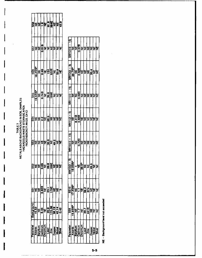
Results of priority pollutant metals analyses of the shallow soils indicate the
presence of several metals above the Base background established during theInstallation Restoration Program investigation. The metals arsenic, cadmium, lead, zinc
and to a limited extent copper, nickel and silver are found in concentrations in excess ofbackground levels. Table 3 tabulates these data.
5.3 Hydrogeology
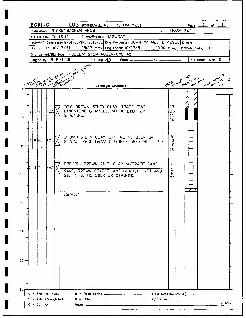
The three well borings advanced at the site during this field investigation,
encountered materials of similar description to those seen previously at this site.
Soil from the ground surface down to eight feet is characterized by a medium brown
silty clay, with trace amounts of pebbles. This layer grades into a grayish silty clay fromeight to 14 feet, with moisture encountered at ten feet. Further description of soil andgroundwater is contained in the Pre-Closure Sampling Report, draft, October 1990.
OMEPC19H3G#WS

AY~
50 0 50
SCALE IN FEETt 0
-4.
-4-
.44-
LEGEND:
74 MONITORING WELL (W/DATUM)7281
UST
-H- STEAM LINE
x FENCE
-728 - GROUNDWATER CONTOUR LINE
SOURCE:
BASE DETAILEDSECTIONAL MAPS

,j
4-"
\X,
FIGURE 5
HAZARDOUS WASTE STORAGE AREAGROUNDWATER ELEVATION MAP
17 OCTOBER 1991
RICKENBACKER ANGB, OHIO
5-7 ES ENGINEERING--SCIENCE

TABLE 4GROUNDWATER ELEVATIONS
17-Oct-91HAZARDOUS WASTE STORAGE AREA
RICKENBACKER ANGB, OHIO
ELEVATIONWELL PROTECTIVE DEPTH TO DEPTH TO GROUNDWATER
CASING FLUID WATER ELEVATION
I RB-HW-MW1 743.43 14.73 14.78 728.69RB-HW-MW2 743.25 -- 14.77 728.38RB-HW-MW3 743.89 -- 15.43 728.46RB-HW-MW4 745.01 -- 15.65 729.36RB-HW-MW5 744.99 Sheen 16.49 728.50RB-HW-MW6 744.99 -- 16.58 728.41RB-HW-MW7 745.16 -- 17.25 727.91RB-HW-MW8 743.74 -- 15.87 727.87RB-HW-MW9 745.12 -- 17.03 728.09
RB-HW-MW10 742.44 -- 14.06 728.38RB-HW-MW11 744.04 -- 15.83 728.21
I RB-HW-MW12 742.87 -- 15.79 728.08
Correction formula for PSH thickness.Assume density of PSH to be 80% that of water[(depth to water - depth to fluid) * 0.8] = correction.Groundwater = depth to water + correction
IIIIIIII 5-8

I
I Water levels in all 12 wells at this site were monitored on 17 October 1991. The
groundwater elevation map generated using this data is illustrated on Figure 5 and
tabulated on Table 4. It confirms groundwater flow to the southeast, and a slight rising
of groundwater potentiometric surface near the USTs.
Wells MW3, MW8 and MW9 exhibited poor recharge during purging and sampling
perhaps indicating severe impact from the dry summer preceding the investigation.According to the Monthly Water Inventory Report for Ohio which is published by the
Ohio Department of Natural Resources, Division of Water, rainfall from May through
October of 1991 was 7.68 inches below normal for the Columbus area.
IIIIIIIiIIII
I*12EC14-W5 3-9

II
SECTION 6.0
I CONCLUSIONS AND RECOMMENDATIONS
6.1 Conclusions
The analytical results indicate soil contamination in throughout the HWSA down todepths of over fifteen feet, as well as contamination of the groundwater with organic
solvents and fuel components. Consequently, removal of all of the contamination, toeffect a clean closure is not a practical option. The extent of contaminants at the HWSA
has been defined, and a closure plan will be compiled for review and approval by the
Ohio EPA.
6.2 Recommendations
I An appropriate remediation method would initiate a groundwater cleanup
engineered to remove contaminants from the groundwater at the site. The surface soilswould remain in place during this operation. When groundwater quality is deemed to beacceptable, determination of status of the soils would be determined. Further
evaluation of the risk to human health and the environment may be necessary duringthis final evaluation. Removal of the USTs at the HWSA is fundamental to instituting
* cleanup of this site.
IIIIIII
I $~192Ei94.3IQW5 -

II
SECTION 7.0
I REFERENCES
Engineering-Science, Inc., Pre-Closure Sampling Report. Hazardous Waste StorageA= draft October 1990, Addendum #6 to the Pre-Closure Sampling Plan
Crano, Nicolas and Eric Ahlgren, "Groundwater Survey, Rickenbacker ANGB, Ohio",October 1991 Burlington Environmental\Mathes Division
IIIIIII
IIII
3 *192E7CI9.3#WS 7.1

IIIIIIUII
APPENDIX A
I MONITORING WELL LOGS/CONSTRUCTION DIAGRAMS
II
IIIIIIII *192EC19436#WS

I AREV DAIE j"R i9B-
BORING LOGI BORING/WELL NO.: RB-HW-MWJO I Page 1 O f
Instollotion: RICKENBACKER ANGB I Site: HWSA-560
project No.: CL115.40 I Client/Project: HAZWRAP
HAZWRAP Contractor: ENGINEERING-SCIENCE Drig Contractor: JOHN MATHES 8 ASSOC Driller:
Drlg Started: 10/14/91 ( 10:55 A m) DrIg Ended: 10/14/91 ( 11:30 A m) Borehole dia(s): 6 I
Drlg Method/Rig Type: HOLLOW STEM AUGER/CME-45Logged by: RLPATTON E-log(Y/, From to _ Protection ieve: .
I . CY,, c
I Lithologic Description C \ ° ' 1 0 p\\ .$o'a ° e("° e'
-II; DRY, BROWN, SILTY CLAY, BROWN AND GREY 11S I Y 16 MOTTLING, NO HC ODOR OR STAINING. 13
5 1312
IiDRY TO DAMP, BROWN, STIFF SILTY CLAY, 5 -
- 2 N 28 NO HC ODOR OR STAINING. 6 -10 - --- 12--
17--I 10-1
GREY, VERY FINE GRAINED SAND WITH TRACE 17- 3 Y 11.4 SILT, NO HC ODOR OR STAIN 8
15 12I 26 -
m BOH=IB'.
E 20-
25
I30 II
35 IU - Thin wall tube R = Rock coring Field G/C(Make/Mod.)
S = Split spoon(tube) 0 = Other G/C Oper.:
C = Cuttings Notes: xx

FIGURE 4.2MONITORING WELL CONSTRUCTION LOG - Double CasedRV.OT:JN99
WELL NO.: MW-10 lInstallation: RICKENBACKER ANGB Site: HWSA-560u 7Iproject No.: CL115.40 IClient/Project: HAZWRAPHAZWRAP Contractor: ENGINEERING-SCIENCE Drig Contractor: MATHES &. ASSOC
Camp. Start: 10/14/91 (11:30 A m) Comp. End: 10/14/91 C13:55 Pm)
BitB:Well Coord: __________________
E~ev.PROTECTIVE CSG
Eegh Material/Type STEEL
Diameter 4__________________________ELev. Depth BGS 3' - Weep Hole ('Height - --------
GUR POT jCS Elev. ___ UR OT ~'CS Height U-00' No. 3 Type STEEL
Depth BGS ~SURFACE PAD 2x'CNRTComposition & Size 2x'CNRT
SURFACE CSCTypeDiameter _____ ____Total length
GROUT:L Setup/Hydration Time__ _____________
Composition & Proportions
Interval BOS_________________ _____
Tremied (Y/N)I~ RISER PIPEType - SCH 40 PVCDiameter 2
Total Length (TOC to TOS)
- - - -- --- Composition & Proportions
interval BGS 0-4' BGS
.CENTSALIZER (YA93 ~ ~~~~~~~~~~~~~Depth(s) ___________________________
TypeSource
6Setup/Hydration Time -______Vol. Fluid Added ______
Tremied (YIN)
FILTER PACKType WASH OTTAWA SANDS
Amount Used 3 BAGS-Source _ _ _ _ _ _ _ _ _ _ _
10 1Cr. Size Dist___________________________Tremnied (YIA
Type SCH 40 VT ~Diameter 2'
18 ~Slot Size & Type 0.010
SuMe ()_______Interval BGS Lnt
Bottom Cap &N) LntI _____________PLUG
MaterialSetup/Hydration Time____________ _________
3 Tremied (Y/N)
I Borehole di
01 15WIDD
I CLI 15.40.03 ES ENGINEERING-SCIENCE
REV DATE .AN. 1989
BORING LOG I BORING/WELL NO.: RB-HW-MW1l I Page of___
installation: RICKENBACKER ANGB ISite: HWSA-560project No.: CL1I5.40 IClient/Project: HAZWRAPHAZWRAP Contractor: ENGINEERING-SCIENCEI Drig Contractor: JOHN MATHES & ASSOCI Driller:IDrig Started: 10/15/91 ( 09:35 Amn) Drig Ended: 10/15/91 (10:30 A m) Borehole dio(s): 6'Drig Method/Rig Type: HOLLOW STEM AUGER/CME-45Logged by: RLPATTON IE-log(Yi/J From _______to _______ Protection level: D
*_L90Ltooi Description p ,al# 0 e
DRY, BROWN, SILTY CLAY, TRACE FINE 13-IY72.3 LIMESTONE GRAVELS, NO HC ODOR OR 25L
5- STAINING. 1916
BROWN SILTY CLAY, DRY, NO HC ODOR OR 9 -S 2 N S5.1 X STAIN, TRACE GRAVEL (FINE), GREY MOTTLING 13 -
18 -
18
-S3Y3. GREYISH-BROWN SILT, CLAY W/TRACE SAND. 6-SAND, BROWN COARSE, AND GRAVEL, WET AND 6-
15 8-1-SILTY, NO HC ODOR OR STAINING. 20 -
I BOH=1B'.
I 20
25-
U = hin wall tube R - Rock coring Field G/C(Moke/Mod.)
S = split spoon(tube) 0 -Other G/C Oper.
C=Cuttings Notes-____________________________________________ OIVI

* FIGURE 4.2KV. DATE! JA" 1989
MONITORING WELL CONSTRUCTION LOG - Double Cased
WELL NO.: MW-11 In1stallation: RICKENBACKER ANGB Tite: HW'SA-56CIproject No.: CL115.40 IClient/Project: HAZWRAPHAZWRAP Contractor: ENGINEERING-SCIENCE Drig Contractor: MATHES &. Assoc.Comp. Start: 10/15/91 C10:30 A m) Comp. End: 10/15/91 C13.3C Pm)!
Built By: Well Coord: ____________________
ELev. ____PROTECTIVE CSQ TEHeight Material/TypeSTE
Diameter 4ELev. Depth BGS 3' - Weep Hole (v/aHeight - ---- GARD POSTS O)'GS Height 0 No. 3Type STrEEL
Depth BGS ~SURFACE PAD ex'CNRTComposition & Size 2'CNET
SURFACE CSGTypeDiameter _____ ____Total length
GOTSetup/Hydration Time_______________Composition & Proportions
Interval BGS_______________________Tremied (Y/N)
R ISER PIPESH4 VType SH4 VDiameter 2'Total Length (TOC to TOS) 10.5
GROUT _
- -- -- -- -- Composititon & roportions
Interval BGS ________________ _____
Tremied (Y 1 ®
* ~~~~~~~Depth(s) ____________
Type 1/4' BENTONITE PELLETSSource W~YDMING
55Setup/Hydration Time -______Vol. Fluid Added 2 GALLNS
Fi ~ Tremied (Y/(S75 FILTER PACK
Type U1TTA\A WdASHED SANDSAmount Used 3 BAGSSource _ _ _ _ _ _ _ _ _ _ _
10Cr. Size Dist___________________________Tremied Cr/N)
Type SCH 40PVT T Diameter 2'17. - -- - - -Slot Size & Type 0.010,
sum1A (YO~17____5_ interval BCS Length
Bottom Cap (Y/N)
BCLL PLUMaterial
T 175Setup/Hydration Time___________ _________
Borehoe digTremied (Y/0)
CLi 15.40.03 ES ENGINEERING- SCIENCE
REY DATE "JJ 1989
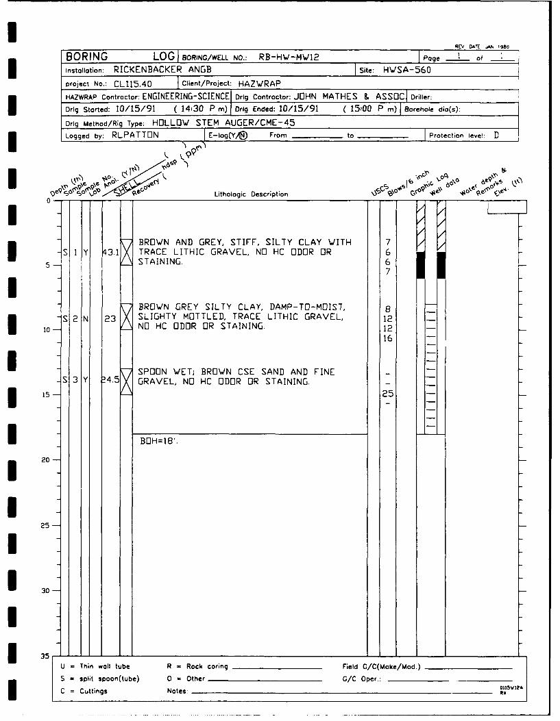
BORING LOG BlORING/WELL NO.: RB-HWbMW12 Page 1of
Installation: RICKENBACKER ANGB ISite: HWSA-560
project No.: CL115.40 IClient/Project: HAZ'SRAP
HAZWRAP Contractor: ENGINEERING-SCIENCEI Drlg Contractor: JOHN MATHES & ASSO Dre:
Drig Started: 10/15/91 ( 14:30 P m) IDrlg Ended: 10/15/91 (25M0 P m) IBorehole dia(s):
Drig Method/Rig Type: HOLLOW STEM AUGER/CME45Logged by: RLPATTON IE-log(Y,® From _______to I______ Protection leve!: D
l 99
0-0
BROWN AND GREY, STIFF, SILTY CLAY WITH 7S 1 Y 43.1 TRACE LITHIC GRAVEL, NO HC ODOR OR 6
5I STAINING.7
BROWN GREY SILTY CLAY, DAMP-TO-MOIST, 8-S 2 N 2:3 SLIGHTY MOTTLED, TRACE LITHIC GRAVEL, 12-I 10 xNO HC ODOR OR STAINING. 12-
16 -
SPOON WETi BROWN CSE SAND AND FINE-5S 3 Y D4.5 GRAVEL, NO HC ODOR OR STAINING.I 15 x25 -
I BOH=18'.
I 20
25
* 30
U - Thin wall tube R - Rock coring Field G/C(Make/Mod.)
S - sitn oon(tube) 0 -Other /C Oper.:

FIGURE 4.2MONITORING WELL CONSTRUCTION LOG - Double Cased REV. DATE: J"N 1989
WELL NO.: MW-12 linstallation: RICKENBACKER ANGB _Site, HWS A -56 0
project No.: CL115.40 ICliet/Project: HAZ\JRAPHAZWRAP Contractor: ENGINEERING-SCIENCE DrIg Contractor: MATHES &. ASSOJC
Comp. Start: 10/15/91 (15:00 P mn) Comp. End: 10/16/91 C11:00 A -)I
Buil By:Well Coord:
ELev. ____PROTECTIVE CSQ
Height ____Materiol/Type STEELDiameter 4
ElLev. Depth BCS 3' Weep Hole GHeight - ------ GUR POT YNCS Elev.____UADPSS(N'CS Height 0.00' No. 3 Type STEELDepth BS SURFACE PAD
Composition & Size 2'x2' CONCRETE
SURFACE CSGTypeDiameter _____ ____Total length
GROUTJI Setup/Hydration Time_______________Composition & Proportions
Interval BGS_______________________Tremied (Y/N)
R ISER PIPESH4 VType SH4 V
Diameter 2_ _ __ _ __ _
Total Length (TOC to TOS) '
3 Composition & Proportions
Interval BCS_______________________
Tremied (Y0CENTRALIZER (YA9Depth(s)_____________________________
4 ]5__ __ _
i~fl Type BENTIJNITE PELLETSSource W/YOM[NG
6 Setup/Hydration Time _____Vol. Fluid Added F GALLONSTremied (Yo
ri - FILTER PACK-Type UTTA'WA SANDS
Amount Used 3 BAGS
10 L10 - Cr. Size DistTremied (Y/N)
Type SCH 40UVDiameter 2'
18 ---- Slot Size & Type 0.010,
.S1JM- (vfi))18 -_________Interval 805 Length
Bottom Cap &N)
BACKILL PLUGMaterial _ _ _ _ _ _ _ _ _
Setup/Hydration Time____________________TO 18 Boeol Tremied (Y/N)
01 15W12E
CLi 15.40.03 ES ENGINEERING- SCIENCE

IIIIIIIII APPENDIX B
I ANALYTICAL DATA VALIDATION NOTES
IIIIIIIII *192EPC194.U#W5

APPENDIX BANALYTICAL DATA VALIDATION NOTES
This appendix presents a summary and review of quality assurance and quality
control results for the laboratory analysis of H20 and soil samples collected during 1991
phase of the site investigation at Rickenbacker Air National Guard Base (the Base) in
Columbus, Ohio. The analyses were performed by Engineering-Science (ES) Berkeley
Laboratory (BL).
The results from ESBL are divided into data packages which are assigned a work
order (WO) number. Each package contains the required quality control
documentation. Contract Laboratory Protocol (CLP) methods were required at the
time of these analyses according to "CLP Laboratory Data Validation EPA Functional
Guidelines for Evaluating Organics and Inorganic Analyses."
Each package was validated by reviewing holding times, method blanks, matrix
spike/matrix spike duplicates and field quality control samples. If the criteria as
specified by the EPA guidelines were not met, action was taken to indicate the
discrepancy. Validation notes will be "flagged" concerning any non-compliance to CLP
protocol.
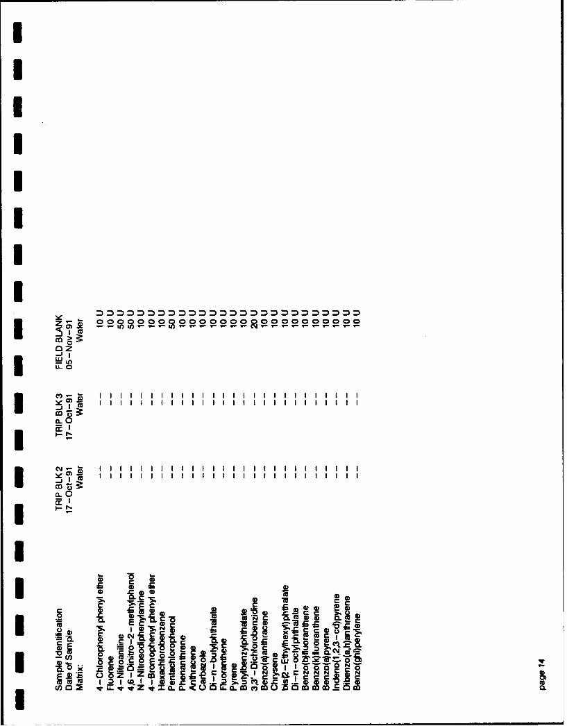
The analytical results of the environmental and quality control samples were
evaluated to assess the representativeness, precision and accuracy, comparability and
completeness of the data. Representativeness was evaluated from the analytical results
of the trip blanks, field blanks, rinseate blanks, method blanks and field duplicate
samples. Precision and accuracy were evaluated by reviewing the laboratory matrix
spike sample (MS), and the matrix spike duplicate sample (MSD). The comparabilitywas evaluated by reviewing duplicate sample results. The completeness was evaluated
by reviewing the chain-of-custody with results.
All samples were analyzed within EPA data validation technical holding times.
Holding times are designated periods by EPA from sampling date to time of analysis.
Data Validation Flags - The following exceptions were outside the CLP acceptance
criteria and were acknowledged, or flagged accordingly. Data contained in Appendix C
of this report, reflect all validation notes.
I92DPC/-.2#WS .1-

In the Method Blank (MSBNA911023) and ES Samples SS4 (3377-04), SS6 (3377-
06), SS9 (3377-07) and 12-3-5 (3377-13), internal standard recoveries failed to meet
acceptance criteria. Analysis of a second aliquot of these samples were conducted and
gave similar results, indicating a possible matrix effect. The results of both analytical
runs are presented; "RA" is appended to the sample identifiers for the second run.
Sample 11-13-15 Matrix Spike (MS) (3377-12MS) showed percent recoveries for n-
nitroso-di-n-propylamine, 1,2,4-trichlorobenzene and pentachlorophenol that were
below acceptance criteria. The Relative Percent Differences (RPD) for 1,2,4-
trichlorobenzene acenaphthene and pentachlorophenol were above acceptance criteria.Analysis of a blank spike indicated the laboratory was in control with respect to these
compounds.
Samples 10-13-15 (3377-10), 12-3-5 (3377-13), and 12-13-15 (3377-14), internal
standard recoveries failed to meet acceptance criteria. Analyses of a second aliquot of
these samples were conducted and gave similar results, indicating a possible matrixeffect. The results of both analytical runs are presented; "RA" is appended to the
sample identifiers for the second run.
Sample 12-13-15 (3377-14) showed high surrogate recovery of two out of three
surrogates. Re-analysis produced acceptance results.
Preparation blanks and all Quality Control (QC) samples were analyzed using both
Inductively Coupled Plasa (ICP) and Graphite Furnace Atomic Absorption (GFAA)methods, resulting in two sets of QC data (one by ICP, one by GFAA) for lead. Allblank results which fall between the ICP Instrument Detection Limit (IDL) and five
times the ICP IDL of lead are flagged with "Y". The GFAA lead results for sample 11-13 is the valid result for that sample. The ICP lead result for this sample is for QCpurposes only.
The serial dilution sample result for zinc did not agree with the undiluted sampleresult for zinc within 10 percent, and the zinc result of the undiluted sample was greater
than 50 times the zinc IDL All zinc results in this batch are therefore flagged with "E".
Some analytical spike recoveries of selenium and thallium were less than 40 percent.These samples were diluted and re-analyzed; analytical spike recoveries were still less
than 40 percent. These selenium and thallium results are flagged with "E".
o192DPC/123.2S#ws .2.

I
In the method blank (MSBN911022) internal standard recoveries failed to meet
acceptance criteria. Analysis of a second aliquot of this sample was conducted and gave
similar results. All associated data were closely inspected. The laboratory has
determined this non-conformance to be an isolated occurrence. The results of both
analytical runs are presented; "RA" is appended to the sample identifiers for the second
un. Sample MW6 (3389-06) showed two surrogates in the base neutral fraction below
acceptance criteria. Re-extraction and re-analysis showed one surrogate above
acceptance criteria. The results of both analytical runs are presented; "RE" is appendedto the sample identifiers for the second run. All target analytes were undetected in
* either of the two analyses.
Sample MW3 (3389-01) showed high surrogate recoveries. Re-analysis gave similarresults, indicating a possible matrix effect. The results of both analytical runs are
presented; "RE" is appended to the sample identifiers for the second run.
IIIIIIIII
61@92D7C/123.234PW$ .3.

IIIIIIIII APPENDIX C
VALIDATED ANALYTiCAL DATA
IIIIIIIII *1~2EPC1944g#WS

II
I LEGEND FOR ORGANIC RESULT QUALIFIERS
I
* U The compound was analyzed for but not detected.
J The value reported is an estimated concentration. Thisis used when:1. The mass spectral data indicate the presence of a
compound that meets identification criteria, butthe result is less than the reporting limit;
2. Estimating the concentration for tentativelyidentified compounds (TICs) where a 1:1 response
* is assumed.
C This is used for pesticide results where identificationhas been confirmed by GC/MS.
B The analyte is found in the associated blank as well asin the sample.
I A A TIC is a suspected aldol-condensation product.
I E This flag identifies compounds whose concentrationsexceed the calibration range of the GC/MS instrumentfor that specific analysis.
D This flag identifies a compound whose reportedanalytical result is calculated from a greater dilutionthan the primary analysis. The actual dilution used tocalculate the analytical result is reported either on
* the report or in the case narrative.
N Indicates presumptive evidence of a compound. Thisflag is only used for TICs, where the identification isbased on a mass spectral library search. It is appliedto all TIC results.I
II

I
I LEGEND FOR INORGANIC RESULT QUALIFIERS
II
I B Reported value is less than Reporting limit butgreater than the IDL.
N Spiked sample recovery not within control limits.
I S Reported value was determined by the Method ofStandard Additions.U
* Duplicate analysis not within control limits.
I W Post digestion spike for Furnace AA analysis out ofcontrol limits (85-115%), while sample absorbanceis less than 50% of spike absorbance.
+ Correlation co-efficient for the MSA is less than0.995.
E The reported value is estimated because of thepresence of interference.
I R Quality Control indicates that data are not usable(compound may or may not be present). Re-sampling
i and re-analysis is necessary for verification.
IIUI
ILEGEND- 1 10/89

I92 R 9A S M R O O R
RIR R A .1 8 co00A
I5 C43t= -V (- -V )C)MC) 7 V
M0 0
I) C') =
0
MO
00
00
o -~ .~ G-S~
ou 0 o- co10o
0- o _ o 0
> rI L' 0Co6 ZU..-. scn i~ 0f., 1

Ag-oono n 0090 0
AM0000000000000co0 00000000000
CO
@ m 000 00 00 0o O OQ O000
C)
Cl)I A9 2 8 8§ 1893fZ99 30 i9
ccIIC E.c fE0
I4 c* oo ooo oo~~ooo~ ~
I C~ 0
m w ) so 0U)0vv v mt~~iaCwcco 5 0 Cc 5c

0
0
000000000000000 00008
0 c
0)0
00
to -a9 If 2C
I0 CMN., C0I 4F , C4 4N C 1c*4VC-

CI
c j - gC'2W
0
co=
0
o
0 CD
CC)
co0I6r, U ~0 100 0-2*4acNP8 O
ccI1 2 OvI LL.C cV o : o c 5i oC

IfIdci c)C) ci C) mC) 0CV V r r V NCI
_0
0
ml N000 0000 0NN000N00N N NNN;
00
a z
C0 SL t ,
ED£
.04II rc 0 8. 1'a 2-I Z! jCfl0~~~ ~ OJ---~c4Jt lc Ic ie

III1IL
00
m-t-
00
m-.:)M-Imv; ;-- V I o 00000000000000000000000
(00
c. 2 8 I0rls M-%CI ,-i C')'§
I~ D I~ ) COCc)'q I~ OC'
IqZ4 C, 2 ,V ,C 0 w )1 sc 0c

?.IL* 0 09 o19aoco 0 8 8 0
I 00
cJo-III
*~~~ Cc I00 ooC000 0 00 0 8
c r 0
0.Igl
L 2 x. fi I *10 t
C=*M l ~ V ~ INYv C~ eCM -A V 'N E V4 l Cl NM, C0

0
m*I0800OO0ONCOCOSCROO OO
S0 000 000 0 00 0 00000 00 000 000
In I cn
-0 0 0 0 0 0 0 0 0 0 0 0 03I
N00 0 00-0m0 0 0cIe
A L)OI jiC 69 m1 12 (qI II I , ~ 0 a c
L-v v CO U.2 *~wcO : MOSS 06

0DW
0 t
00
rII0
0 0 s t ) )0
a
M ~ ~ ~~~ 'a I z 5 I5002z l~I, _u I- 5 LIV L)xL
CI cy oc! qc0ylt v Ii0 q '0V t 't

0) ------------- ----------
I
0I1- -I -I I I I i - I I I I - - - - - - - - - - -
I IoIooIoI ooIoI oeIoI IoII I oII ooI ooIIo
0I1I
0
I
II
I°
I . 0
_-- - - - - - - - -
ww - w~ ~ -- -- - -- --
;DZ ~
a)~

Ic
- --------------- ---------- W----- Lf---)---
I ~--- - ------------ ----- -------DCO
-a) 7a ----------------------- ----- )-tl--
0* E'0J E ooo oo oo ooo oo oo oo ooo)oo oo
0 ~ ---- C-- --- --- --- -- - -- -- -- I
0
82~ ~ ~ 0 sXS0 b 05850 i
IV 00 X 0 q u EL x _ zOCL~.~ Co cy IM NNo 0 0,Z , ":0 v: "t Cm cYc'

-- _ -------11 1 I 11 1 11
IIc
0 0
0 '
-~~Z. 6) ---- -- -- -- - --
0f0
(n 0 0 L L L o

III L
FI
CL0
0 I
I u~ 0Ia -J weIIIIIIIIIIIIIIIII-E S r0
a0 0 D0RaCr
1 I. I iE 25 50 ZE(R Z i 5t
I~U W q cq :I I Ooi I oCLMV xc ~
ZI O O C O O OO O O O O 0 0IC
Ic
ICL 0
o.0.o
=5 .5CLC d,
4)1 -6 £l - Os- 60
2 CL I 1 U 5c 5'Sn a vvZ' LC c nm 5 c OO

C)
0
IP
n0
o
0
00
8. o4 8 -a~ ~ z~ aa.5C1 S
>- 0 a" 5 5 )u

0
in
fn II I I I I I I I I I I I I I iCh
0
I 0
0
0
S= owe -S M1IIr
00 1 Cii5 -8~ .~ n n-1.1S& )i 2 (M)4 oI- I )XF

---------- --- ----------------
I Ic ---- ------- --------------
-1 c
I- O c c - - - - - - - - - - - - - - - -
0
-I C
Iw
00
0 E l
Io IIN l f-00 fa.1 .1 0 w(h o cS01- J L

0II
c'cm
I - ---- --- --- ----------------- ------
c'JQE-I mcI i
0~- Oki 4In ~= ~ --- ---- --- --- ---- --- --- --M* q
Ilga I I NJC.J
Mn e a C--5 --- -- -- -- -- -- -- - -aC- q AIoVc, 4L
ccI0 ' oi 0 L

0
0
0
CO -
U)~ ~~~ c--- -- - - - -- !--- - - -
CC
AD .1 wM

-- -. 000 -O-O -- - -- - -- - -- 0- -- 0-0-- -0---
-- -- - - -- -- -- -- -- -- - -- - -- - --
0 0
0
C Cu
-- ~~i Z- -2 "- C- e000 00 'r) 000050 0 0 00BIr-0q N0g z z .*51 rC .0-~~~0 ~ CY 00 0 ~ 0 0 0 0 0 0 0 0 0 0 0 0 0 w

IjII
I --------- --- -- ------------------
CL 0
-- ----I- --I-
IC
CL 0
0 . 0 80 C
s- - E o cya*~ E
cIO co 0VIl0 I Cl 0.oINeuI " " I CAZc

E
00
-0) 0 CI 056w6o6 -
E E
-00 IT 0l-000l llE E
coE
z
-~~ Ci)O M .- 6O D- M&g Mo
E EE0I1
co z
0 f MI
00
IZ*Z CD D U
U) q nM $( ) c
to 0 4 N~~- . 4_n cn c -a - S *IE E4cOOC~N ~ ~ ~ O.JZOfIN ~ *a

Ia tE E iii III III-
0
ZII 3mu~Z4.
0
Z4
00C CO m .OOO
o E E0
0 o
DI)C C )u
I 6 E0
zI1
0 E E
I 0
> CL.
c. 0 0 . c mcoo~ 0 4 1*Ccn 0 - r4 a 2 Zct0.

IZ
aon E 0~00~
o0
E EKI0
z z
,1 - ONVJ ocmooo-E EI0
0 'tII II lIi II I I II I'~cl :" ( I I IllI I l -
0 E
MA cc
In 1 2IE
0 0
~C* ~ 2 *
0 cy
I..

0
= LE E
-l)I cC)ci
I
04E E
IO v N ' w 0 C') 00m
Z. z
-00- 0q 0 r6-0 E E
-0I
M 0,Ina2< o )U0_ a NIIL Z0 22c =

IIc0
I~ -J
-o v co c;t
0
I -J
I C"
0<
COCLC c')J C ('C abz
0
I ZZ! WzI. u30oc oIl DV)q f
I LEDo
w~ -It
C CI
S
E E E ?I 2~ o.' _ 0
CLft-

I<Iz
0-0
z Zz z w:L
-CO'CO MC m mJM MIY CO, - r, CD0
0
z z
ZZZ Z~~~~~3 wJ O~....'.N CO
zz m mmm-r
I 3: w-aC O6~ -oO c' C'jNc N z
0
I<0
00
I .3to
I~ co ..
OO...J Z a.

MIommM M )nMDcI q q C q qId
IlI0
0-
~jI
CL 0
0
Q (A
IL aIocIm ). 4) C~)c )000