csni/wg-risk – level 2 psa and accident management workshop – march 20041 status of irsn level 2...
TRANSCRIPT

CSNI/WG-RISK – LEVEL 2 PSA AND ACCIDENT MANAGEMENT WORKSHOP – MARCH 2004
1
STATUS OF IRSN LEVEL 2 PSA(PWR 900)
•General objectives
•Content of the study
•Level 1 to Level 2 Interface
•Quantification of physical phenomena with uncertainties in APET
•A model for containment leakage through containment penetrations
•Radioactive releases model
•KANT : a quantification software for level 2 PSA

CSNI/WG-RISK – LEVEL 2 PSA AND ACCIDENT MANAGEMENT WORKSHOP – MARCH 2004
2
General objectives
A level 2 PSA for French 900 MW PWR
• to contribute to reactor safety level assessment,• to estimate the benefits of accident management procedures,• to provide quantitative elements about advantages of any reactor design or operation modifications,• to acquire quantitative knowledge for emergency management teams,• to help in definition of RD programs in the severe accident field• learning from detailed studies are also extended to other French Plants

CSNI/WG-RISK – LEVEL 2 PSA AND ACCIDENT MANAGEMENT WORKSHOP – MARCH 2004
3
Steps
•2000 - version (1.0) based on IRSN level 1 PSA published in 1990 – power states of reactor
•2003 – version (1.1) - revision of 1.0 - power states of reactor
•2004 – version 2.0 - updated level 1 PSA – response surfaces method for uncertainties assessment - hydrogen recombiners
•2005 – version 2.1 – shutdown states of reactor

CSNI/WG-RISK – LEVEL 2 PSA AND ACCIDENT MANAGEMENT WORKSHOP – MARCH 2004
4
Content
General methodology initially based on NUREG 1150
1. Binning of level 1 PSA sequences in PDS2. Representation of important severe accident
events in an APET3. Binning of level 2 PSA into Release Categories4. Assessment of radioactive releases for each
release category5. Uncertainties assessment by Monte-Carlo method

CSNI/WG-RISK – LEVEL 2 PSA AND ACCIDENT MANAGEMENT WORKSHOP – MARCH 2004
5
A detailed interface between level 1 to level 2 PSA
•20 interfaces variables serve to define the Plant Damage States and concern initiator event, system and containment state, residual power, activation of emergency plan.
PT – RCS break sizeSF – Component cooling or essential service water systems
PL – RCS break localization AP – Water makeup to RCS availability
RT – SGTR number BA – Safety injection water tankVL – V-LOCA SE – Secondary system breakAS – CHRS availability SO – Pressurizer safety valve availability
BP – Low pressure safety injection availability IE – Containment isolation
HP – High pressure safety injection availability CR – Core criticity
GV – SG availability PR – Residual power
LC – Electrical board availability (low voltage) PU – Emergency plan
LH – Electrical board availability (high voltage) RS – Electrical network availability
CSNI/WG-RISK – LEVEL 2 PSA AND ACCIDENT MANAGEMENT WORKSHOP – MARCH 2004
6
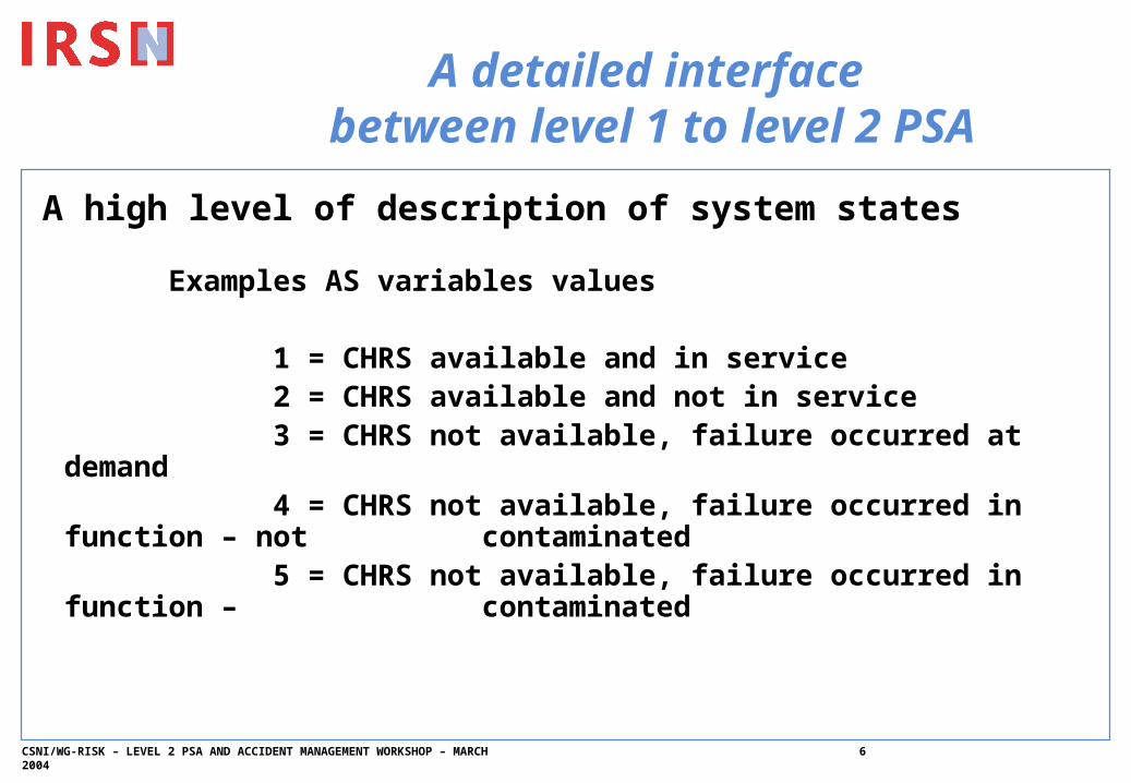
A detailed interface between level 1 to level 2 PSA
A high level of description of system states
Examples AS variables values
1 = CHRS available and in service2 = CHRS available and not in service3 = CHRS not available, failure occurred at
demand4 = CHRS not available, failure occurred in
function – not contaminated5 = CHRS not available, failure occurred in
function – contaminated

CSNI/WG-RISK – LEVEL 2 PSA AND ACCIDENT MANAGEMENT WORKSHOP – MARCH 2004
7
A detailed interface between level 1 to level 2 PSA
150 Plant Damage States have been defined for power states. A representative thermal-hydraulics transient is defined for each PDS
Number of PDS Number ofthermal-hydraulics
transients
LOCA (large break) 17 9
LOCA (medium break) 24 14
LOCA (small break) 8 8
LOCA (very small break) 10 10
SGTR 20 15
Secondary break 13 13
Loss of heat sink 13 10
Loss of steam generator water injection
17 17
Total loss of electrical power 12 6

CSNI/WG-RISK – LEVEL 2 PSA AND ACCIDENT MANAGEMENT WORKSHOP – MARCH 2004
8
A detailed interface between level 1 to level 2 PSA
Thermal-hydraulics transient are calculated with the SCAR version of the simulator SIPA 2 (that includes CATHARE 2).
Advantages of this approach :
– to obtain a better evaluation of accident kinetics and delays before releases,
– to consolidate level 1 PSA assumptions,– to define more precise conditions for severe acc. Phenomena,– to provide a large panel of « best-estimated » transients for
use in other context (accident management team, safety analysis)

CSNI/WG-RISK – LEVEL 2 PSA AND ACCIDENT MANAGEMENT WORKSHOP – MARCH 2004
9
APET – Quantification of physical phenomena with uncertainties
The different physical phenomena are organized in « physical models » :
– each physical model represents a set of physical phenomena that are tightly coupled ;
– 2 separated models are linked by a limited numbers of variables transmitted by the APET

CSNI/WG-RISK – LEVEL 2 PSA AND ACCIDENT MANAGEMENT WORKSHOP – MARCH 2004
10
Physical models of APET
Level 1 PSAPlant Damage State
Before Core degradation
During Core degradation
Vessel Rupture
Corium-Concrete Interaction
Before core degradation
I- SGTR
During Core Degradationn
Advanced core
degradatio
CombustionH2
In-vessel steam
explosion
Direct ContaintHeating
Containment mechanical behavior
Corium concrete
interaction
Combustion
Ex-vessels.e.

CSNI/WG-RISK – LEVEL 2 PSA AND ACCIDENT MANAGEMENT WORKSHOP – MARCH 2004
11
Physical models of APETCodes
Construction of physical model based on results obtained by validated codes calculations. Expert’s judgments are used for result interpretation or when direct code calculations are note possible
In-vessel progressionIn-vessel
progressionAdvanced core
degradationAdvanced core
degradation
In-vesselexplosionIn-vesselexplosion
Direct containmentheating
Direct containmentheating
Ex-vesselprogressionEx-vessel
progression
Containment mechanicalbehaviour
Containment mechanicalbehaviour
VULCAIN+CPA(ASTEC V0)
specific models
MC3D + EUROPLEXUS
RUPUICUV+CPA(ASTEC V0)
CORCON+CPA
CAST3M
Induced breaksInduced breaks
ThermalhydraulicsThermalhydraulics
SCAR
ICARE-CATHARE + specific mechanical calculations
In-vessel progressionIn-vessel
progressionAdvanced core
degradationAdvanced core
degradation
In-vesselexplosionIn-vesselexplosion
Direct containmentheating
Direct containmentheating
Ex-vesselprogressionEx-vessel
progression
Containment mechanicalbehaviour
Containment mechanicalbehaviour
VULCAIN+CPA(ASTEC V0)
VULCAIN+CPA(ASTEC V0)
specific modelsspecific models
MC3D + EUROPLEXUSMC3D + EUROPLEXUS
RUPUICUV+CPA(ASTEC V0)
RUPUICUV+CPA(ASTEC V0)
CORCON+CPACORCON+CPA
CAST3MCAST3M
Induced breaksInduced breaks
ThermalhydraulicsThermalhydraulics
SCARSCAR
ICARE-CATHARE + specific mechanical calculations
ICARE-CATHARE + specific mechanical calculations

CSNI/WG-RISK – LEVEL 2 PSA AND ACCIDENT MANAGEMENT WORKSHOP – MARCH 2004
12
Physical models of APETTwo methods are employed
METHODE 1 : RESPONSE SURFACES
Downstream variables values = F(upstream variables values)(Details provided in second workshop presentation)
METHODE 2 : GRID OF RESULTS
•For core degradation progression strong scenario effects and discontinuities have to be taken into account (valve opening, RCS cooling by SG, RCS water injection …)
•Construction of response surfaces would be a very difficult task
•Grid of result approach is used
CSNI/WG-RISK – LEVEL 2 PSA AND ACCIDENT MANAGEMENT WORKSHOP – MARCH 2004
13
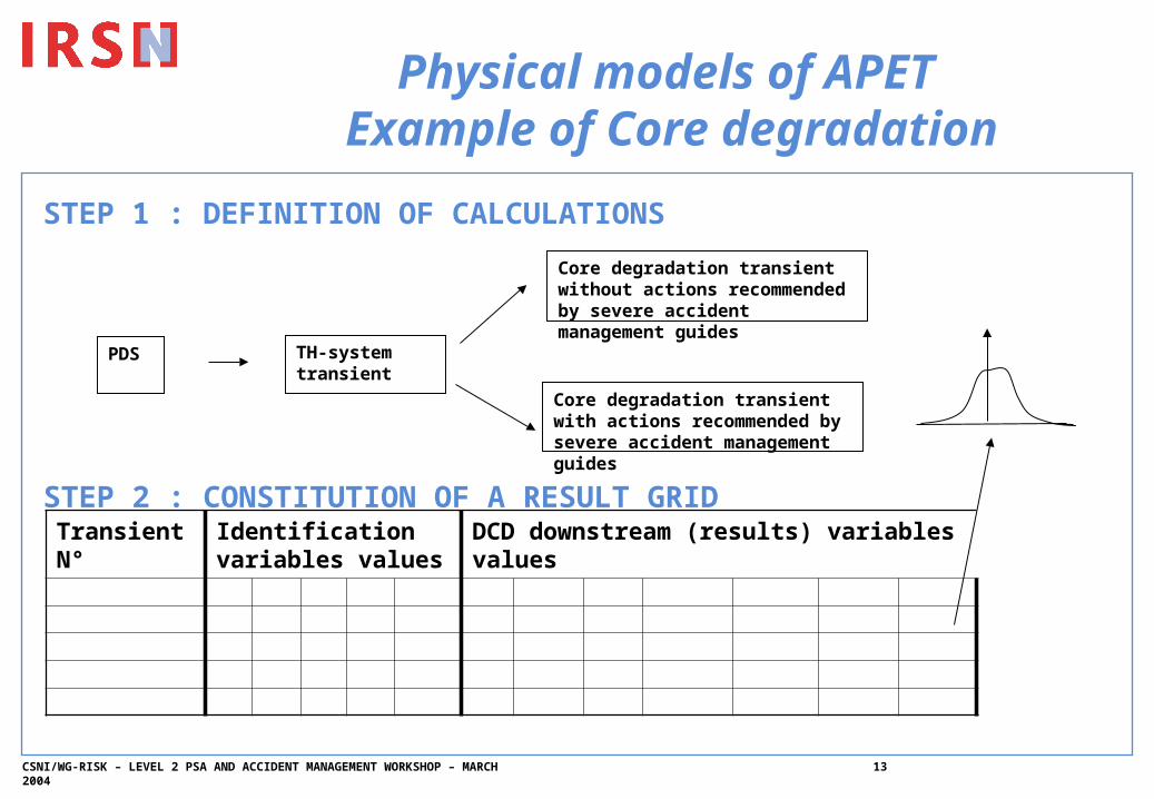
Physical models of APET Example of Core degradation
STEP 1 : DEFINITION OF CALCULATIONS
STEP 2 : CONSTITUTION OF A RESULT GRID
Core degradation transient without actions recommended by severe accident management guides
TH-system transient
Core degradation transient with actions recommended by severe accident management guides
PDS
Transient N°
Identification variables values
DCD downstream (results) variables values

CSNI/WG-RISK – LEVEL 2 PSA AND ACCIDENT MANAGEMENT WORKSHOP – MARCH 2004
14
Physical models of APET Example of Core Degradation
STEP 3 : RESULT GRID IN THE APET
•ONE SCENARIO DEPENDS ON SYSTEM AVAILIBILITY, HUMAN ACTIONS, RESIDUAL POWER …
•A SELECTION TREE SELECTS THE MOST REPRESENTATIVE TRANSIENT IN THE RESULTS GRID
•THE DOWNSTREAM VALUES ARE EXTRACTED FROM THE RESULTS GRID FOR THE REPRESENTATIVE TRANSIENT

CSNI/WG-RISK – LEVEL 2 PSA AND ACCIDENT MANAGEMENT WORKSHOP – MARCH 2004
15
Leakage through containment penetrations« mode »
•A specific method has been developed to take into account pre-existing leakage or isolation failure during the accident
•A specific software, BETAPROB has been developped
•A model is constructed :
– System description (hydraulics components, valves, pumps, sumps, rooms of auxiliary building and ventilation/filtration level)
– Failure probabilities (, failure in operation, , failure on demand)
– Severe (100 % section) and non severe (1% section) are distinguished)

CSNI/WG-RISK – LEVEL 2 PSA AND ACCIDENT MANAGEMENT WORKSHOP – MARCH 2004
16
Leakage through containment penetrationsAPET Model
For each system configuration, BETAPROB calculates all the possible leakage paths and proposes a classification of leakage paths as a function of
- Nature of release source (liquid from RCS or gaseous from containment atmosphere)
- Transfer mode to environment in function of ventilation systems and filtration
- Leakage section
In the APET, for each systems configurations are calculated
- Probabilities of leak categories in term of leakage section- Probabilities of leak categories in term of filtration efficiency

CSNI/WG-RISK – LEVEL 2 PSA AND ACCIDENT MANAGEMENT WORKSHOP – MARCH 2004
17
The radioactive releases calculation model
A simplified model has been developed for level 2 PSA.
Each level 2 sequence is characterized by « APF » variables that give information on accident progression and containment failure.
The model can calculate radiaoactive releases as a time function of time for each combination of APF variables.
Uncertainties have been taken into account for most influent parameters.

CSNI/WG-RISK – LEVEL 2 PSA AND ACCIDENT MANAGEMENT WORKSHOP – MARCH 2004
18
The radioactive releases calculation model
Fission product emission
Noble
Gases
Melt - corium 1100 °C
First corium
flow
Vessel Break
Volatil
molecular iodineProgressive Aerosol Emission

CSNI/WG-RISK – LEVEL 2 PSA AND ACCIDENT MANAGEMENT WORKSHOP – MARCH 2004
19
Fission products behavior in containment
Containment atmosphere composition
– Aerosol mass in suspension depends on : emission, energetic phenomena in RCS (steam explosion) or in containment (Combustion), natural deposition, spray system (CSHRS) efficiency and containment leakage
– Molecular iodine depends on : emission, painting adsorption, spray system (CSHRS) efficiency and containment leakage
– Organic iodine depends on : adsorbed molecular iodine to organic iodine and containment leakage
– Noble gases depends on : emission and containment leakage
Radioactive releases depend on
– Containment leakage size (mass flow), – Containment atmosphere composition,– Aerosol filtration and iodine retention,– Activity as a function of delay after SCRAM
CSNI/WG-RISK – LEVEL 2 PSA AND ACCIDENT MANAGEMENT WORKSHOP – MARCH 2004
20
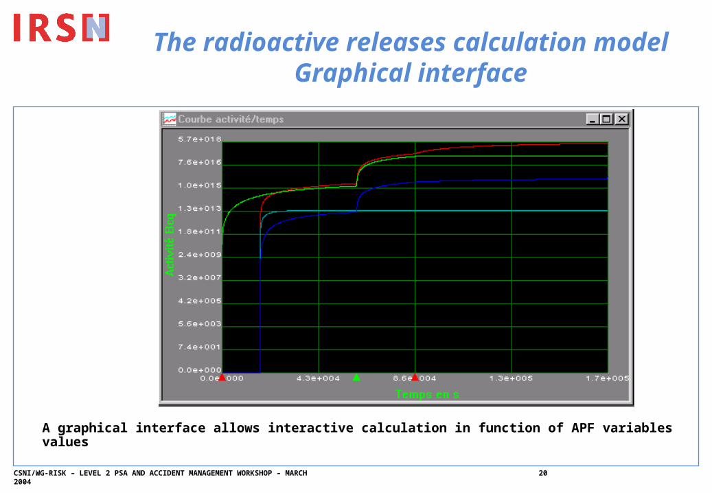
The radioactive releases calculation model
Graphical interface
A graphical interface allows interactive calculation in function of APF variables values

CSNI/WG-RISK – LEVEL 2 PSA AND ACCIDENT MANAGEMENT WORKSHOP – MARCH 2004
21
KANT A software for level 2 PSA
quantification•A specific software, able to take into account the specifities of the IRSN methodologies has been developed.
•The software is linked with the releases model
•Operational for Windows operating system (C++, MFC, Access)
•3 main modules :– APET development (subtrees, specific language for model)– APET quantification (Monte-Carlo method)– Results vizualization

CSNI/WG-RISK – LEVEL 2 PSA AND ACCIDENT MANAGEMENT WORKSHOP – MARCH 2004
22
KANTExample of results vizualization

CSNI/WG-RISK – LEVEL 2 PSA AND ACCIDENT MANAGEMENT WORKSHOP – MARCH 2004
23
KANTPerspectives
Future Improvements
– Extension of functionalities in terms of results presentation
– Identification and quantification of early radioactive releases
– Graphical presentation of the APET
– A convivial interface to give access to main results

CSNI/WG-RISK – LEVEL 2 PSA AND ACCIDENT MANAGEMENT WORKSHOP – MARCH 2004
24
Conclusions
A detailed level 2PSA for French 900 MW is performed by IRSN with some specifities
– Systematic use of validated codes– Original models (containment leakage, human factor)– Detailed interface and large transient calculation– A specific software, KANT, operational since 1998, with a
development program
•Future– 2004 – Analysis of French Utility approach for level 2 PSA– 2004 – Version 2.0 for power states of reactor
(recombiner, …)– 2005 – Version 2.1 for shutdown states of reactor– 2006 ? Improvement of methods (dynamic fiability ?,
interface ?), Other plant application (?)