csme congress 2020 design of a multi-body pipe inspection
TRANSCRIPT

Proceedings of the Canadian Society for Mechanical Engineering International Congress 2020CSME Congress 2020
June 21-24, 2020, Charlottetown, PE, Canada
Design of a Multi-body Pipe Inspection Robot1st Cuautli Garcia
School of Electrical Engineeringand Computer ScienceUniversity of Ottawa
Ottawa, [email protected]
2nd Eric LanteigneDepartment of Mechanical Engineering
University of OttawaOttawa, Canada
3rd Wail GueaiebSchool of Electrical Engineering
and Computer ScienceUniversity of Ottawa
Ottawa, [email protected]
Abstract—This paper presents a new hypermobile robot forinspecting pipes of different diameters. The robot is composedof three modules, two driving modules and one control modulewhich are linked by a passive joint. The driving module has eightactuators: four gearmotors to propel the robot along the pipe, andfour servomotors to control the radial position of the robot in thepipe and to maintain the robot’s balance. A Raspberry Pi is usedto control the actuators, acquire sensors feedback, and receivecommands from a remote wireless user-controlled GUI. A set ofpreliminary experimental tests was conducted to demonstrate theeffectiveness of the system.
Index Terms—Inspection robot, in-situ pipe inspection, hyper-mobile robot
I. INTRODUCTION
As a result of string growth in U.S. and Canadian oil andnatural gas production, pipeline capacity is expected to becomeconstrained in the future, requiring new pipelines and pipelineexpansions to provide access to new markets. There are morethan 840.000 km of transmission, gathering and distributionpipelines in Canada, according to the Natural ResourcesCanada. These pipelines are aging and increasing demandsposed by harsher service conditions stress the importance ofintegrity management [1]. As such, leakage detection andmaintenance are crucial.
Generally, a pipeline is a network of connected pipes withpumps, valves and control devices to help convey liquids orgases. A pipeline network consists of gathering systems, trunklinks and distribution systems. The latter is the longest of thenetwork. Typically, the pipes making the distribution systemare of a small diameter and operate at low pressure.
Pipelines operate year round and computerized operationallows pressure, flow and energy consumption throughout theline to be continuously monitored. Software can perform leakdetection calculations quickly and initiate remedial actions incase of emergency. However, research suggests that operatingstations identify only about 15-20 percent of the total pipelineleaks [2].
According to the Canadian Energy Pipeline Association,sophisticated technology allows operators to see anything outof the ordinary, like minute cracks or signs of corrosion, frominside the pipe. Like a small submarine, devices called smart
pigs (pipe inspection gauge) are used for inline inspection.These devices are not autonomous. Rather, they move alongwith the fluid. An autonomous robot is a widely acceptedmethod for collecting data, including images, of pipes withoutor with little human intervention. To this end, several au-tonomous mobile robots for small diameter pipe inspectionhave been proposed [3], [4].
The goal of this research is to validate the theoretical robotdesign presented in [3], [4]. The proposed mobile robot designis comprised of three modules: two propulsive modules anda control module. It can travel inside pipelines between 154and 203 mm (6" and 8") in diameter and negotiate bends of0 to 180◦.
This article describes the mechanical systems developed toachieve the desire motion capabilities and the implementationof the electronic controller architecture. The remainder of thepaper is organized as follows: Section II explores existing in-pipe robot morphologies. Section III describes the theoreticaland computer-aided design of the proposed robot. Section IVoutlines the electronic system implementation. Experimentalresults are provided and discussed in Section V, followed bya few concluding remarks and suggestions for future research.
II. RELATED WORKS
Most in-situ pipe robots have been designed for specificapplications and can be classified into several elementarycategories according to their locomotion, as shown in Fig. 1.
Fig. 1. Classification of in-pipe robots [5]

The pig type illustrated in Fig. 1(a) is one of the most well-known commercial in-situ pipe robots. It is passively drivenby the fluid pressure and, as a consequence, cannot executesophisticated movements. Okamoto et al. developed a pig typerobot that has a cylindrical capsule which is connected torubber discs by passive joints which allows the capsule torotate around its longitudinal axis. The principal purpose ofthe rubber discs is to block the fluid and to propel the robot;however, the discs maintain the radial position of the capsule.It is also equipped with multiple ultrasonic sensors directed tothe pipeline to analyze the inner wall of the pipeline [6].
The wheeled in-situ pipe robots, shown in Fig. 1(b), canmove smoothly and fairly quickly along horizontal pipes dueto the convenience of wheel-based locomotion. However, theycannot operate inside vertical or inclined pipes. Round ductsor pipes which can typically be represented as a cylindricalworkspace are the most common geometrical shapes, and thuswheeled robots working in round ducts/pipes are the mostcommon practices [7]. As an example, Song et al. developed acontroller for guiding wheeled mobile robots inside cylindricalworkspaces. The prototype is a car-like mobile robot withwheels of 120mm of radius. The robot was programmed tonavigate with a low speed of 3m/min inside 250mm radiuspipes [8].
Crawler or Caterpillar type robots, illustrated in Fig. 1(c),are similar to wheeled robots but are characterized with ahigher traction which can be useful in certain conditions, suchas slippery surfaces or inclined pipes. Nonetheless, they stillcannot propel themselves in vertical pipes [9].
Support or Wall-press robots are depicted in Fig. 1(d). Theycan adapt their structure to pipes of varying diameters, but theyusually need another propulsive module to provide the steeringmovement inside fittings. The structure of this type of robot issuitable for long-range inspection and it can also carry heavyloads [10]. The robot presented by Kwon et al. can inspect apipeline between 80 and 100mm. It uses two driving modulesconnected by a compression spring. The modules are offset by60◦ to help with the robot’s agility. Each module is constructedas a triangular linkage structure to maintain its alignment withthe pipe while having a caterpillar wheel on each side of thetriangular structure. The caterpillar wheel is made of two gearsand a wrapping silicon belt for a large friction coefficient [11].
Kin et al. developed a robot that is somewhere betweencrawler and support type. The robot can locomote in pipesbetween 600 and 800mm. It uses pneumatic cylinders toadjust to the pipe surface while having tracks along therobot [12].
A crawl type robot, illustrated in Fig. 1(e), is able to movethrough horizontal and bending pipes. However, it cannotlocomote along vertical or inclined pipes. Yu et al. developed awalking robot for horizontal pipes that uses a support platformwith four passive wheels connected to the robot by springs toadapt itself to different diameter pipes. The propulsion of the
robot is realized by 14 gears transmitting the motor’s motioninto two axes that rotate at different rates [13].
A creep type robot is shown in Fig. 1(f). It is reliablefor inspecting vertical/inclined pipes because it is capable ofapplying a great force to the pipe wall. It can also adapt todifferent diameter pipes. This robot usually has two modulesconnected by a joint that can rotate and separate both modules.Zhang et al. presented this type of structure as a squirm piperobot with magnetic wheels that use the creep principle tonavigate along the pipe [14]. Another creep robot presentedby Kejie et al. is able to move in horizontal, vertical andbending pipes while adapting 90 to 150mm diameter pipes.Nevertheless, it is not autonomous. As a matter of fact, it mustbe tethered to the controller and the batteries [15].
The screw drive in-pipe robot (SDIR), illustrated inFig. 1(g), requires only one motor to drive within the pipe.This greatly simplifies the mechanical structure as well asthe control system. However, just like creep-type robots,this type of robot also has the tendency of getting jammedinside the pipe. SDIRs are wall-pressed, which allows themto easily climb vertical pipes [16]. Kakogawa et al. presenteda screw drive in-situ pipe robot that uses only two actuatorsto navigate through a bent pipe and T-branch between 109and 129mm of diameter. The robot has three different controlmodes. Screw-driving mode, for forward/backward movement;steering mode, to navigate through branch pipes or elbows, androll mode, to change its navigation direction in pipes where itcannot steer [7].
A snake-type robot is shown in Fig. 1(h). It has multiplemodules with terrain adaptability by means of wheel or footlocomotion. Thus, a snake-like robot has the greatest potentialfor application to industrial pipe inspection [17]. An SPC robotdeveloped by Dai et al. is a spiral pipe-climbing robot that canexpand or contract to vary its size as needed. It is able to adaptto pipes of different diameters. It is a wheeled multi-modulestructure, where each module can spin to better face othermodules [5].
With the above features in mind, a combination of snake-and support-type robot is potentially the most suitable setupfor industrial in-situ pipe inspection robots. This is due to thestructure’s flexibility and adaptability to move along a varietyof pipe configurations: horizontal, vertical, reduction and bentpipes.
III. PROPOSED DESIGN
The robot architecture is based on the theoretical work ofDouadi et al. [3], [4] and the preliminary design of Lam-onde [18]. Their effort laid the foundation of the mechanicaldesign and a computational framework of a 2-dimensionalkinematics and dynamics of the robot. The concept consists ofmultiple (semi-)clone modules of identical dimensions. Eachmodule is equipped with four independent arms with active

shoulder joints. Each arm has an active wheel joint. Themodules are connected through passive joints, as shown inFig. 2.
Fig. 2. General robot architecture
This multi-joint robot architecture has the advantage ofoffering enough degrees of freedom to escape possible sin-gularities while the robot navigates along the pipe, especiallyaround sharp turns [3], [4].
The robot concept shown in Fig. 2. does not take inconsideration the physical components required to achieve thedesired motion. A preliminary investigation by Lamonde [18]determined that a passive free-floating module would beneeded to accommodate the power pack required for au-tonomous locomotion.
As a first prototype, a robot with three modules were built.The two modules at the front and back of the robot are drivingmodules, to help locomote the vehicle, whereas the middlemodule is the control module which carries the main electron-ics (Raspberry Pi, battery, etc.). Each driving module has fourarms around the module that can be activated independently.A detailed breakdown of the module components is providedin Fig. 3 and Table I.
Fig. 3. Architecture of the prototype robot
The driving modules have two principal mechanisms: aworm drive at location C and a gear drive at location B.The robot arms are driven by 180◦ digital servomotors thatmove the worm screws which are meshed with the wormgears. Fig. 4 shows an exploded view of the propulsive moduleinternal frame and the worm gear mechanism for a single arm.The propulsion is provided by a gearmotor coupled to a bevelgear. This right angle drive allows the gearmotors to be placedalong the arm axis. The bevel gears and gearmotors havereduction ratios of 1:2 and 1000:1, respectively. The gear ratiowas chosen to reduce the torque requirements while providing
TABLE ICOMPONENTS OF THE PROTOTYPE ROBOT
Label Part Name ProperitiesA Wheel AluminumB Gearmotor 1000:1, 32 rpm, 0.8 NmC Worm gear mechanism Alloy steel, ratio of 0.1:1D Digital servomotor 180◦, 1.3 NmE IMU 6 DOFF Universal joint Max. operating angle: 45◦G Motor driver 1.7A output currentH Raspberry Pi and servo HAT Version 3B+I Batteries 7.4V, 3AJ Voltage converter for motors 6V, 15AK Voltage converter for Ras Pi 5V, 3A
the required range of motion, and to fit inside the modulebody. The gearmotor ratio was selected with the peak torquerequired in the wheel shafts when there is a change in thediameter of the pipe. The peak torque is 0.43N·m and it wasobtained by simulation in [3]. Therefore, the minimal torquefor the gearmotor is 0.22N·m and the selected gearmotor hasa peak torque of 0.8N·m. The arm component arrangementis shown in Fig. 5. At no-load, the drive produces a forwardvelocity of 2.76 cm/s.
Fig. 4. Worm mechanism explosion
The arm shoulder holds the worm gear with a set screw.It can also hold a torsion spring to partially support themass of the module. It is divided into two parts to facilitatethe machining process while avoiding any deflection on theshoulder caused by the gear mechanism stress.

Fig. 5. Arm explosion
The driving module components are primarily machinedfrom stock aluminum to avoid deflection in the structures dueto the torque applied by the servomotor and the gearmotor.Non-load bearing components, such as the plate holding theservomotor and the complete control module, are made usinga 3D printer to reduce the cost and weight in the fabricationprocess.
IV. MOTION CONTROL
The long-term goal of the project is to build an autonomousrobot which can navigate, collect data, and generate reportsabout the anomalies along the pipe surface. To achieve fullautonomy, a series of milestones need to be accomplished. Asa first step, the motion control system is tested in open-loopmode. To that end, a bidirectional wireless communicationlink is established between the robot’s main processing unit(Raspberry Pi) and a remote human-operated base computer.A graphical user interface (GUI) application is developed torun on the base computer to dispatch commands to the motorsand to read and analyze data from the electronics aboard therobot. For example, signals from eight encoders connected tothe propulsion gearmotors and two Inertial Measurement Unit(IMU) are transmitted regularly to the base computer. Thepower stage has eight motor drivers, one for each gearmotor,and one Servo HAT for the eight servomotors.
Fig. 6 depicts a block diagram of the electrical componentsaboard of the robot along with their interconnections. Thecontrol, analysis and communication protocols are written inPython. However, the data transfer is established via Secure
Shell (SSH). The GUI is displayed with Xming. The ServoHAT uses a PCA9685 integrated circuit which is an I2C-buswith 16 channels. Each channel has its own 12-bit resolution(4096 steps) that operates in a programmable frequency of 24to 1526Hz with an adjustable duty cycle from 0 to 100 %.Thanks to the PWM adaptability in the output channels, halfof the channels are programmed to control the servomotorswithin 0 to 180◦. The other half is programmed to commandPWM signals to the motor drivers. These are DRV8838brushed motor drivers which enables the speed control of themotors with two inputs: Phase and Enable. The Phase pinscomes from the Raspberry Pi to change the rotational directionof the motor depending of the received value. The Enable pinscome from the Servo HAT. The received signal is a PWM pulsethat varies the speed of the gearmotors from 0 to 32 RPM.
Fig. 6. Block diagram of the robot electronics
The IMU uses a MPU6050 chip with a dual 3-axis gy-roscope and accelerometer. Since the robot naturally twists inthe pipe the module’s inclination must be determined to adjustits position inside the pipe. To do so, gravity measurementsread by the accelerator are converted to inclination angles, asillustrated in Fig. 7. The figure shows the reference positionand the rotation plane with the generated components and an-gles used to convert the gravity measurements into inclinationangles [19]. The angles are calculated using:
θ = atan2 (−AY,OUT ,−AZ,OUT ) (1)
ψ = atan2 (−AX,OUT ,−AZ,OUT ) (2)
where AX,OUT , AY,OUT and AZ,OUT are the IMU’s angularaccelerations about the X , Y , and Z axes, respectively. Theyield angles in (1) and (2) have an interval of [−180◦,+180◦],where −180◦ is the same as +180◦. This method assumesquasi-static or constant velocity and that the primary acceler-ation measurement is due to gravity.

Fig. 7. Rotation planes with components and angles [19]
A flowchart of the communication protocol between theGUI and the robot is depicted in Fig. 8. This communicationstrategy is adopted to test individual sensors and actuators inopen-loop control mode. It will be replaced at a later stage ofthe development by an autonomous feedback loop to track therobot’s desired trajectory inside the pipe.
Fig. 8. Flowchart of the GUI’s communication algorithm with the robot
V. ASSEMBLY AND TESTING
The prototype with two driving modules and one controlmodule has a total length of 58 cm and a total mass of2.75 kg. The control module hosts two 1500mAh 2S 25Clithium-polymer batteries, the on-board computer, the ServoHAT, voltage converters and the drivers for the gearmotors.It also carries two driving boards to hold the wires runningthrough the module. Each of the two propulsive modules runs13 cables distributed as follows: 2 for each gearmotor, 1 foreach servomotor, and 1 for each IMU sensor.
Preliminary motion tests were conducted to run the robotback and forth along 84 cm inside a 6-inch clear pipe withan average speed of 2.47 cm/s. A photo shot of the setup isshown in Fig. 9.
A series of power consumption tests were performed on theprototype with and without load (the load is the weight ofthe robot). In the first test, all the electronics were turnedon while the robot is at rest. In the second and the thirdtest, the robot is set to, respectively, activate four or eightservomotors simultaneously. In the fourth and the fifth test,all eight gearmotors are set to operate at 50% and 100%of their full speeds, respectively. The last two tests were toactivate all the actuators simultaneously at 50% and 100%of the gearmotors full speed. The results of these tests aresummarized in Table II.
The fourth and the fifth tests suggest that, when the gear-motors are being used at full speed the power consumption isless than at medium speed because at this rate the gearmotorsdemand less energy. The last two tests suggest that the robotmust avoid the movement of the gearmotors at medium speedand the servomotors at the same time because this configu-ration consumes more energy than any other. However, thisconfiguration could be performed during navigation throughbent pipes or during the adaptation into a new pipe diameterwhich is less common in pipe inspections.
TABLE IIRESULTS OF THE POWER CONSUMPTION TESTS
Test Component Current Power1 On-board computer and drivers 0.45A 3.37W2 4 Servomotors 1.67A 12.52W3 8 Servomotors 2.50A 18.75W4 8 Gearmotors at 50% 2.35A 17.62W5 8 Gearmotors at 100% 1.00A 7.50W6 8 Servomotors / 8 Gearmotor at 50% 2.60A 19.50W7 8 Servomotors / 8 Gearmotors at 100% 1.45A 10.87W
To study the robot’s endurance a last test was conducted.This test turned on all the electronics and actuators using afully charged battery of 3000 mAh at 7.4 V. Then, the robotmoved with full speed back and forth along the pipe. Duringthis test the servomotors were driven from 0 to 180◦ every5 minutes. The robot was able to sustain this test for 54consecutive minutes, which provides an idea of the autonomytime of the robot.
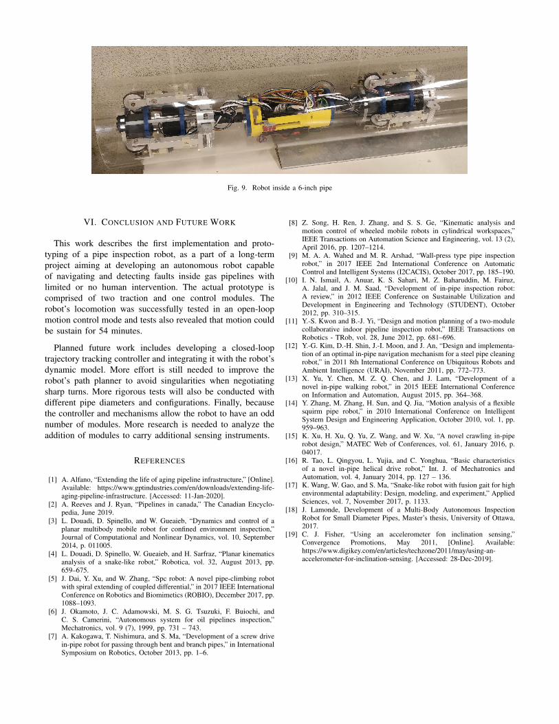
Fig. 9. Robot inside a 6-inch pipe
VI. CONCLUSION AND FUTURE WORK
This work describes the first implementation and proto-typing of a pipe inspection robot, as a part of a long-termproject aiming at developing an autonomous robot capableof navigating and detecting faults inside gas pipelines withlimited or no human intervention. The actual prototype iscomprised of two traction and one control modules. Therobot’s locomotion was successfully tested in an open-loopmotion control mode and tests also revealed that motion couldbe sustain for 54 minutes.
Planned future work includes developing a closed-looptrajectory tracking controller and integrating it with the robot’sdynamic model. More effort is still needed to improve therobot’s path planner to avoid singularities when negotiatingsharp turns. More rigorous tests will also be conducted withdifferent pipe diameters and configurations. Finally, becausethe controller and mechanisms allow the robot to have an oddnumber of modules. More research is needed to analyze theaddition of modules to carry additional sensing instruments.
REFERENCES
[1] A. Alfano, “Extending the life of aging pipeline infrastructure,” [Online].Available: https://www.gptindustries.com/en/downloads/extending-life-aging-pipeline-infrastructure. [Accessed: 11-Jan-2020].
[2] A. Reeves and J. Ryan, “Pipelines in canada,” The Canadian Encyclo-pedia, June 2019.
[3] L. Douadi, D. Spinello, and W. Gueaieb, “Dynamics and control of aplanar multibody mobile robot for confined environment inspection,”Journal of Computational and Nonlinear Dynamics, vol. 10, September2014, p. 011005.
[4] L. Douadi, D. Spinello, W. Gueaieb, and H. Sarfraz, “Planar kinematicsanalysis of a snake-like robot,” Robotica, vol. 32, August 2013, pp.659–675.
[5] J. Dai, Y. Xu, and W. Zhang, “Spc robot: A novel pipe-climbing robotwith spiral extending of coupled differential,” in 2017 IEEE InternationalConference on Robotics and Biomimetics (ROBIO), December 2017, pp.1088–1093.
[6] J. Okamoto, J. C. Adamowski, M. S. G. Tsuzuki, F. Buiochi, andC. S. Camerini, “Autonomous system for oil pipelines inspection,”Mechatronics, vol. 9 (7), 1999, pp. 731 – 743.
[7] A. Kakogawa, T. Nishimura, and S. Ma, “Development of a screw drivein-pipe robot for passing through bent and branch pipes,” in InternationalSymposium on Robotics, October 2013, pp. 1–6.
[8] Z. Song, H. Ren, J. Zhang, and S. S. Ge, “Kinematic analysis andmotion control of wheeled mobile robots in cylindrical workspaces,”IEEE Transactions on Automation Science and Engineering, vol. 13 (2),April 2016, pp. 1207–1214.
[9] M. A. A. Wahed and M. R. Arshad, “Wall-press type pipe inspectionrobot,” in 2017 IEEE 2nd International Conference on AutomaticControl and Intelligent Systems (I2CACIS), October 2017, pp. 185–190.
[10] I. N. Ismail, A. Anuar, K. S. Sahari, M. Z. Baharuddin, M. Fairuz,A. Jalal, and J. M. Saad, “Development of in-pipe inspection robot:A review,” in 2012 IEEE Conference on Sustainable Utilization andDevelopment in Engineering and Technology (STUDENT), October2012, pp. 310–315.
[11] Y.-S. Kwon and B.-J. Yi, “Design and motion planning of a two-modulecollaborative indoor pipeline inspection robot,” IEEE Transactions onRobotics - TRob, vol. 28, June 2012, pp. 681–696.
[12] Y.-G. Kim, D.-H. Shin, J.-I. Moon, and J. An, “Design and implementa-tion of an optimal in-pipe navigation mechanism for a steel pipe cleaningrobot,” in 2011 8th International Conference on Ubiquitous Robots andAmbient Intelligence (URAI), November 2011, pp. 772–773.
[13] X. Yu, Y. Chen, M. Z. Q. Chen, and J. Lam, “Development of anovel in-pipe walking robot,” in 2015 IEEE International Conferenceon Information and Automation, August 2015, pp. 364–368.
[14] Y. Zhang, M. Zhang, H. Sun, and Q. Jia, “Motion analysis of a flexiblesquirm pipe robot,” in 2010 International Conference on IntelligentSystem Design and Engineering Application, October 2010, vol. 1, pp.959–963.
[15] K. Xu, H. Xu, Q. Yu, Z. Wang, and W. Xu, “A novel crawling in-piperobot design,” MATEC Web of Conferences, vol. 61, January 2016, p.04017.
[16] R. Tao, L. Qingyou, L. Yujia, and C. Yonghua, “Basic characteristicsof a novel in-pipe helical drive robot,” Int. J. of Mechatronics andAutomation, vol. 4, January 2014, pp. 127 – 136.
[17] K. Wang, W. Gao, and S. Ma, “Snake-like robot with fusion gait for highenvironmental adaptability: Design, modeling, and experiment,” AppliedSciences, vol. 7, November 2017, p. 1133.
[18] J. Lamonde, Development of a Multi-Body Autonomous InspectionRobot for Small Diameter Pipes, Master’s thesis, University of Ottawa,2017.
[19] C. J. Fisher, “Using an accelerometer fon inclination sensing,”Convergence Promotions, May 2011, [Online]. Available:https://www.digikey.com/en/articles/techzone/2011/may/using-an-accelerometer-for-inclination-sensing. [Accessed: 28-Dec-2019].