csl4 21 j15
TRANSCRIPT
ELECTRICAL ELECTRONICS COMMUNICATION INSTRUMENTATION
Control Systems
Lecture 4
ELECTRICAL ELECTRONICS COMMUNICATION INSTRUMENTATION
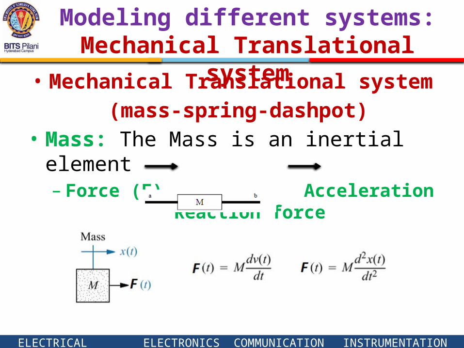
Modeling different systems: Mechanical Translational system
• Mechanical Translational system (mass-spring-dashpot)
• Mass: The Mass is an inertial element– Force (F) Acceleration Reaction force
ELECTRICAL ELECTRONICS COMMUNICATION INSTRUMENTATION
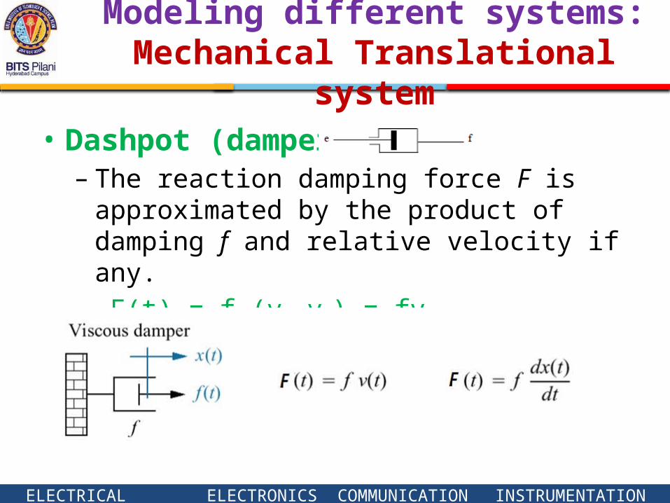
• Dashpot (damper)– The reaction damping force F is approximated by
the product of damping f and relative velocity if any.
– F(t) = f (v1-v2) = fv
Modeling different systems: Mechanical Translational system
ELECTRICAL ELECTRONICS COMMUNICATION INSTRUMENTATION
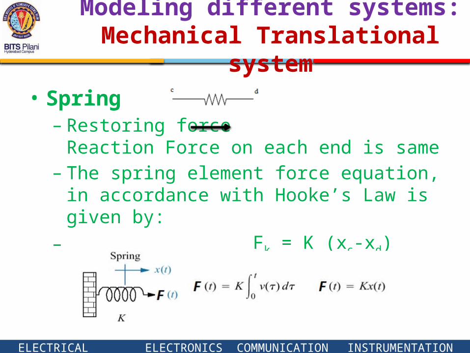
• Spring – Restoring force Reaction Force on each
end is same– The spring element force equation, in accordance
with Hooke’s Law is given by:
– Fk = K (xc-xd)
Modeling different systems: Mechanical Translational system
ELECTRICAL ELECTRONICS COMMUNICATION INSTRUMENTATION
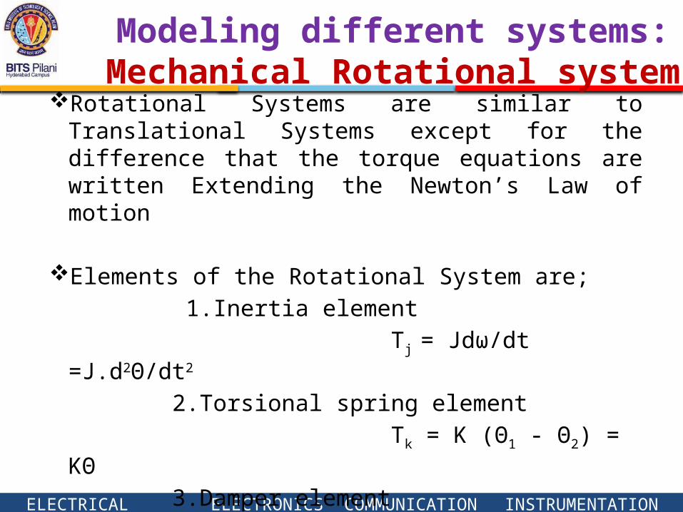
Modeling different systems: Mechanical Rotational system
Rotational Systems are similar to Translational Systems except for the difference that the torque equations are written Extending the Newton’s Law of motion
Elements of the Rotational System are;
1.Inertia element
Tj = Jdω/dt =J.d2ϴ/dt2
2.Torsional spring element
Tk = K (ϴ1 - ϴ2) = Kϴ
3.Damper element
TB = B (ω1 – ω2) = Bω
ELECTRICAL ELECTRONICS COMMUNICATION INSTRUMENTATION
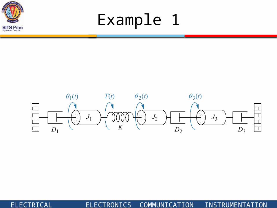
Example 1
ELECTRICAL ELECTRONICS COMMUNICATION INSTRUMENTATION
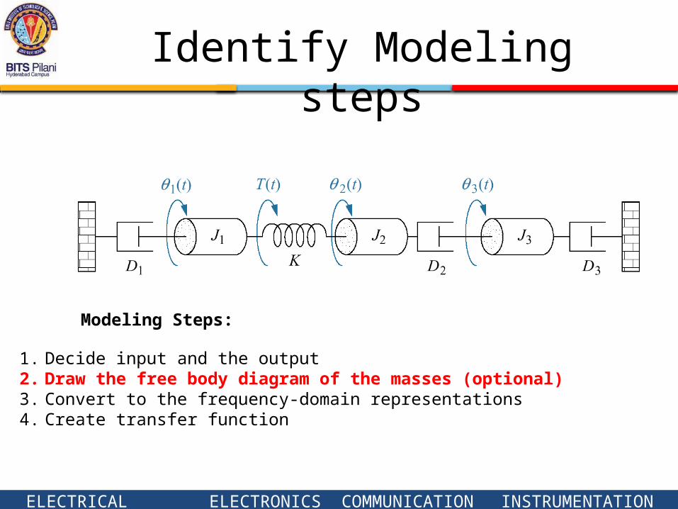
1. Decide input and the output2. Draw the free body diagram of the masses (optional)3. Convert to the frequency-domain representations4. Create transfer function
Modeling Steps:
Identify Modeling steps
ELECTRICAL ELECTRONICS COMMUNICATION INSTRUMENTATION
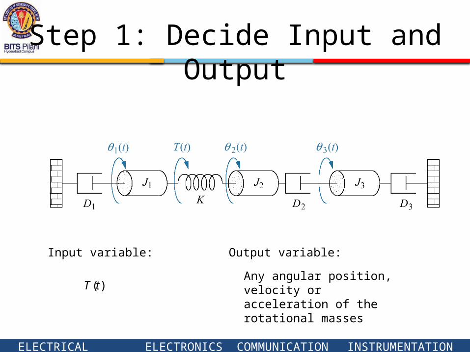
Step 1: Decide Input and Output
)(tTAny angular position, velocity or acceleration of the rotational masses
Output variable:Input variable:
ELECTRICAL ELECTRONICS COMMUNICATION INSTRUMENTATION
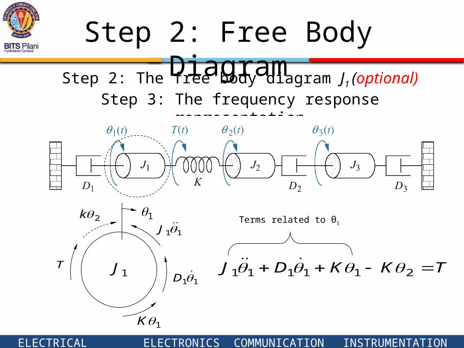
Step 2: The free body diagram J1 (optional)Step 3: The frequency response representation
111J
1J11D
1K
2k
TKKDJ 211111 T
Terms related to θ1
Step 2: Free Body Diagram
ELECTRICAL ELECTRONICS COMMUNICATION INSTRUMENTATION
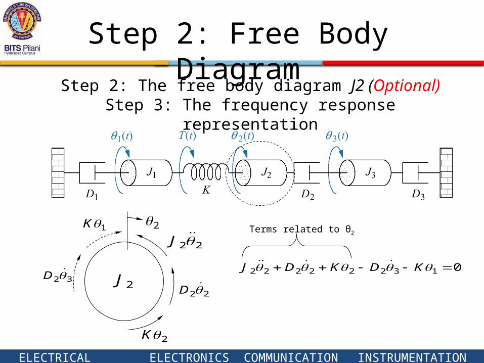
2
22J
2J22D
2K
32D
1K
013222222 KDKDJ
Terms related to θ2
Step 2: The free body diagram J2 (Optional)Step 3: The frequency response representation
Step 2: Free Body Diagram
ELECTRICAL ELECTRONICS COMMUNICATION INSTRUMENTATION
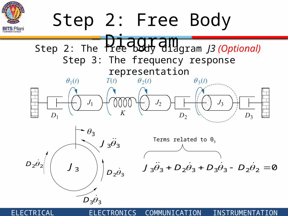
3
33J
3J32D
33D
22D 022333233 DDDJ
Terms related to θ3
Step 2: The free body diagram J3 (Optional) Step 3: The frequency response representation
Step 2: Free Body Diagram
ELECTRICAL ELECTRONICS COMMUNICATION INSTRUMENTATION
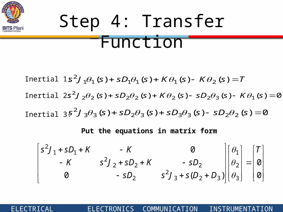
Step 4: Transfer Function
0
0
)(0
0
3
2
1
3232
2
2222
112 T
DDsJssD
sDKsDJsK
KKsDJs
Inertial 1:
Inertial 2:
Inertial 3:
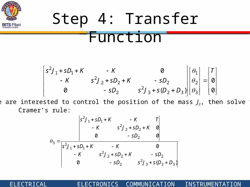
TsKsKssDsJs )()()()( 2111112
0)()()()()( 132222222 sKssDsKssDsJs
0)()()()( 223332332 ssDssDssDsJs
Put the equations in matrix form
ELECTRICAL ELECTRONICS COMMUNICATION INSTRUMENTATION
Step 4: Transfer Function
If we are interested to control the position of the mass J3, then solve for θ3.Cramer’s rule:
)(0
0
00
0
3232
2
2222
112
2
222
112
3
DDsJssD
sDKsDJsK
KKsDJs
sD
KsDJsK
TKKsDJs
0
0
)(0
0
3
2
1
3232
2
2222
112 T
DDsJssD
sDKsDJsK
KKsDJs

ELECTRICAL ELECTRONICS COMMUNICATION INSTRUMENTATION
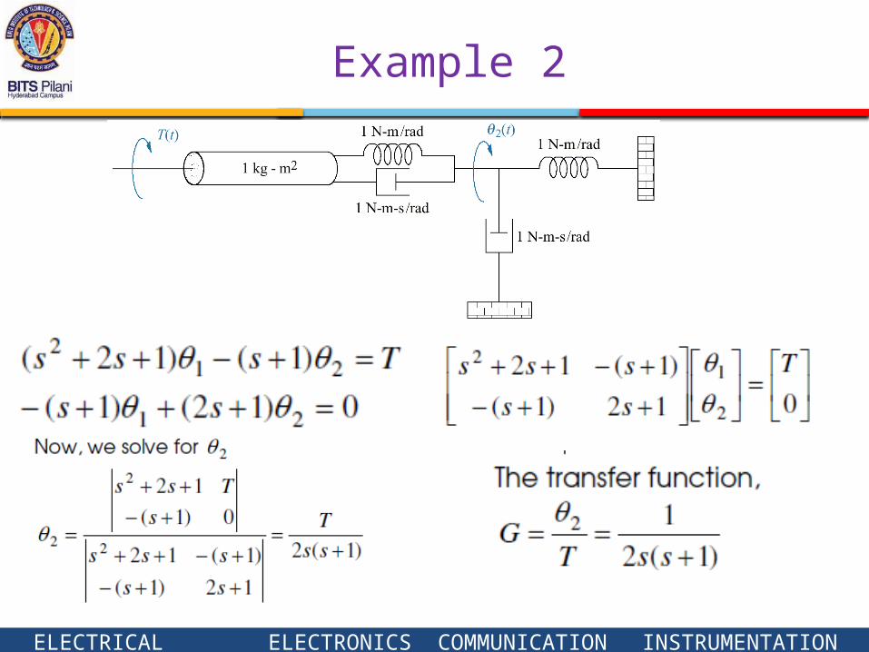
Example 2
Find the transfer function between )( and )( 2 ttT
ELECTRICAL ELECTRONICS COMMUNICATION INSTRUMENTATION
Example 2