cs800 series commercial/industrial pressure reducing regulators · 2020-01-11 · figure 1. typical...
TRANSCRIPT

Figure 1. Typical CS800 Series Pressure Reducing Regulator
Features and Benefits• Flow-optimized disks provide the maximum flow
for your application• Largest number of overpressure protection
offerings in the industry• Wide variety of body sizes and end connections• Body materials available in gray cast iron,
ductile iron and steel
• Fixed Factor/Pressure Factor Measurement (PFM) accuracy capabilities
• Only standard tools required for pressure adjustment and orifice removal
• Simplified maintenance• Optional stabilizer cartridge
CS800 Series Commercial/Industrial Pressure Reducing Regulators
TYPE CS800 REGULATOR
P1235
P1521
TYPE CS803 REGULATOR WITH TRUE-MONITOR ™ PROTECTION
P1234
TYPE CS800IQ WITH HIGH CAPACITY RELIEF
P1692
TYPE CS804IT REGULATOR WITH INTEGRAL TYPE VSX8 SLAM-SHUT MODULE
Bulletin 71.1D103140X012 CS800 SeriesJuly 2019
SpecificationsThe Specifications section lists the specifications for the CS800 Series Regulators. The following information is stamped on the nameplate of CS800 Series: Type Number, Maximum Outlet Pressure and Spring Range.
Available ConfigurationsSee Table 1
Body Sizes, Material, End Connection and Pressure Rating(1)
See Table 2Maximum Inlet Pressures(1)
Emergency: 175 psig / 12.1 barOperating: See Table 3
Maximum Outlet Pressure(1)
Emergency (Casing): 15 psig / 1.0 barTo avoid internal parts damage: 3 psig / 0.21 bar differential above outlet pressure setting
Outlet Pressure Ranges(1)
Regulator: 3.5 in. w.c. to 10 psig / 9 mbar to 0.69 bar See Table 4
Internal Relief PerformanceApproximate Internal Relief Start-to-Discharge Point: See Table 5Relief Performance:For Standard Internal Relief: See Figures 9, 11, 13, 15, 17 and 19For High Capacity Internal Relief: See Figures 10, 12, 14, 16, 18 and 20
Token Relief PerformanceApproximate Token Relief Start-to-Discharge: See Table 5Maximum Token Relief Discharge Capacities: See Figure 8
Flow CapacitiesWith Standard Construction: See Tables 14 through 18 and 20 through 62With True-Monitor™ or Slam Shut: See Tables 14 through 62With Secondary Seat™ Construction: See Tables 63 through 77With Low Inlet Option(3): See Tables 19 and 64
Orifice Sizes, Flow Coefficients and IEC Sizing Coefficients
See Table 3Temperature Capabilities(1)(2)
-20 to 150°F / -29 to 66°C
Spring Case Vent ConnectionInternal Relief: 1 NPTHigh Capacity Relief: 2-1/2 NPT
External Registration Connection 3/4 NPT
Spring Case Vent and Body OrientationSee Figure 21
Secondary Seat Approximate Lockup Values and Associated Internal Relief Start-to-Discharge:
See Table 6TM600 Series True-Monitor Performance(1)
Inlet Pressure RatingsMaximum Operating: Up to 125 psig / 8.6 barMaximum Emergency: 175 psig / 12.1 bar
Outlet Pressure Range: 12 in. w.c. to 7.5 psig / 30 mbar to 0.52 bar
Type VSX8 Slam-Shut Device(1)
Maximum Inlet Pressure: 175 psig / 12.1 barMaximum Operating Inlet Pressure: 175 psig / 12.1 bar
Construction MaterialsCS800 Series Main Valve and ActuatorBody: Gray Cast Iron, Ductile Iron or SteelBody O-ring: Nitrile (NBR)Closing Cap: AluminumAdjusting Screw: Aluminum, Brass or Zinc-plated steelUpper and Lower Case: AluminumValve Stem: Aluminum or Zinc-plated steelDiaphragm Head: Zinc-plated steelOrifice:Standard: AluminumSecondary Seat: Brass
Pusher Post or Internal Relief Valve Seat: Aluminum or Zinc-plated steel Diaphragm and Disk: Nitrile (NBR)Control Spring: Stainless steel or SteelRelief Valve Spring: Stainless steelRelief Valve Spring Retainer: Aluminum or Zinc-plated steelVent Screen: Stainless steelRetaining Ring: Stainless steel or Zinc-plated steelLever Pin: Stainless steel or hardened steelSpring Seat: AluminumLever: Steel
1. The pressure/temperature limits in this Bulletin or any applicable standard or code limitation should not be exceeded. 2. Product has passed Emerson Process Management Regulator Technologies, Inc. testing for lockup, relief start-to-discharge and reseal down to -40 degrees.3. Applies to Capacities with Low Inlet Option, which offers Enhanced Flow Performance at Low Inlet pressures for the 2 in. / DN 50 body with 5.5 to 8.5 in. w.c. / 13 to 21 mbar spring range.
- continued -
2
CS800 Series

Specifications (continued)
Construction Materials (continued)Type TM600 True-Monitor™ ActuatorDiaphragm Case, Spring Case and Balanced Port Assembly Housing: AluminumDiaphragm Retainer and Diaphragm Head:Zinc-plated SteelValve Stem: AluminumDiaphragm: Nitrile (NBR)Disk Holder and Disk Retainer: BrassDisk/Seat Contact: Nitrile (NBR)Monitor Stem: Stainless steelMiddle Diaphragm Retainer: Zinc-plated steelControl Spring: Stainless steelVent Screen: Stainless steelVent Retaining Ring: Zinc-plated steelClosing Cap: AluminumAdjusting Screw: AluminumO-rings: Nitrile (NBR)
Type VSX8 Slam-Shut DeviceDiaphragm Case, Spring Case, Diaphragm Plateand Valve Stem: AluminumDiaphragm and Disk: Nitrile (NBR)
Construction Materials (continued)Type VSX8 Slam-shut Device (continued)Control Spring: Music Wire or Stainless steelVent Screen: Stainless steelVent Screen Retainer: Zinc-plated steelClosing Cap: AluminumAdjusting Screw: Aluminum
Designed, Tested and Evaluated Consistent with: ASME B16, ASME Section VIII DIV I and ASTM B117 (Corrosion Resistance)
Approximate WeightsWith Threaded Body Type CS800/CS820: 25 lbs / 11 kg Type CS803/CS823: 34 lbs / 15 kgType CS804/CS824: 31 lbs / 14 kgType CS805/CS825: 26 lbs / 12 kgType CS806/CS826: 26 lbs / 12 kg
High-Pressure Types: For Type CS85x add 2 lbs / 0.9 kg to types listed aboveWith Flanged BodyAdd 11 lbs / 5.0 kg to weights listed above
Table 1. Available Configurations
TYPE NUMBEROPTIONS
C S 8OUTLET PRESSURE CONSTRUCTION
0 Low Pressure Applications (Outlet Pressure: 3.5 to 30 in. w.c. / 9 to 75 mbar)2 Medium Pressure Applications (Outlet Pressure: 1 to 5.5 psig / 69 mbar to 0.38 bar)5 High Pressure Applications (Outlet Pressure: 5 to 10 psig / 0.34 to 0.69 bar)(1)
OVERPRESSURE PROTECTION MODULE0 Without Overpressure Protection Module3 With Integral True-Monitor Module(4)
4 With Slam-shut Module(4)
5 With Secondary Seat™ Protection6 With Secondary Seat Protection with controlled bleed to indicate Secondary Seat is functioning(2)
PRESSURE REGISTRATIONI Internal RegistrationE External Registration(3)
RELIEFN Non-RelievingR Internal ReliefQ High-Capacity ReliefT Token ReliefL Low Flow Token Relief
SC Stabilizer CartridgeExample: Type Number CS800IR: Type CS800 regulator without Overpressure Protection Module with Internal Pressure
Registration and with Internal Relief.1. High-pressure Construction is not available with True-Monitor Protection, Secondary Seat Protection or Relief.2. Available only with Internal Relief or High-Capacity Relief Constructions.3. Available only with Non-Relieving or Token Relief Constructions.4. Reference Instruction Manual D103126X012 for information regarding the Type TM600 Integral True-Monitor or
Instruction Manual D103127X012 for Type VSX8 safety Slam-shut module.
3
CS800 Series

Figure 2. Internal View of CS800 Series with High Capacity Relief
IntroductionThe CS800 Series direct-operated, spring-loaded regulators have been engineered to fit a multitude of commercial and industrial pressure-reducing applications. This flexibility is provided by the numerous body sizes and end connections, outlet pressure settings, orifice sizes, as well as the option for internal or external pressure registration.
FeaturesStabilizer Cartridge OptionThe stabilizer cartridge is designed to eliminate harmonic instability in such applications where there can be humming/buzzing, meter feedback or high efficiency boiler feedback.
Overpressure Protection Options Available• Internal Relief—Provides overpressure protection
to the downstream system by relieving gas through the diaphragm assembly to atmosphere in the event of an overpressure situation.
• High-Capacity Internal Relief—Provides an increase in relief performance over internal relief thereby offering a significant improvement in the
RELIEF VALVE SEAT
VENT STABILIZER
VALVE DISK
ORIFICE
DIAPHRAGM ASSEMBLY
ADJUSTING SCREW
LEVER
CONTROL SPRING
VALVE STEM
RELIEF SPRING
P1002
level of overpressure protection to the downstream system in the event of an overpressure occurrence.
• True-Monitor™ Protection—Combines the operation of a conventional two-regulator wideopen monitor set into one body. Provides a second monitoring regulator to control downstream pressure. In event of loss of downstream pressure control by the primary regulator due to damage to the lever, downstream sense line, orifice, disk, diaphragm, etc., the monitoring regulator will assume control of the downstream pressure and regulator flow.
• Secondary Seat™ Protection—Provides a solution to the most common cause of regulators failing to shut off by employing a secondary seating surface to provide shutoff in the event the primary orifice seating surface becomes damaged or blocked. See page 15 for additional information.
• Slam-Shut Protection—Discontinues gas service by shutting the gas off if there is an overpressure or underpressure condition.
Overpressure Relief• Token Relief – Provides overpressure relief via a
small capacity or token relief that relieves minor overpressure caused by thermal expansion or minor nicks in the orifice or disk.
4
CS800 Series

Table 3. Inlet Pressure Ratings and Flow and Sizing Coefficients
ORIFICE SIZEMAXIMUM OPERATING INLET PRESSURE
TO OBTAIN OPTIMUM PERFORMANCEMAXIMUM
EMERGENCY INLET PRESSURE
WIDE-OPEN FLOW COEFFICIENTS IEC SIZING COEFFICIENTS
psig Setpoints In. w.c. Setpoints
In. mm psig bar psig bar psig bar Cg Cv C1 XT FL FD
1/4(1) 6.4(1) 125 8.6 125 8.6 175 12.1 50 2.1 24.6 0.38 0.89 0.99
3/8 9.5 125 8.6 125 8.6 175 12.1 110 3.8 29.5 0.55 0.89 0.90
1/2 13 100 6.9 100 6.9 175 12.1 210 7.2 29.5 0.55 0.89 0.93
5/8 16 80 6.5 60 4.1 175 12.1 320 10.1 31.8 0.64 0.89 0.88
3/4 19 80 6.5 60 4.1 175 12.1 450 13.3 34 0.73 0.89 0.84
7/8 22 60 4.1 50 3.4 175 12.1 600 16.7 36 0.82 0.89 0.81
1(1) 25(1) 30 2.1 25 1.7 175 12.1 765 20.1 38.1 0.92 0.89 0.77
1-3/8(1)(2) 35(1)(2) 15 1.0 15 1.0 175 12.1 1125 29.8 37.7 0.90 0.89 0.76
1. Not available on the Types CS805, CS806, CS825 and CS826.2. Not available on the Types CS803 and CS823.
Table 2. Body Sizes, Materials, End Connections and Maximum Cold Working Pressure Ratings(5)
TYPE BODY MATERIAL END CONNECTIONBODY SIZE FACE-TO-FACE DIMENSION BODY INLET PRESSURE RATING
In. DN In. mm psig bar
CS800, CS805, CS806, CS820,
CS825, CS826 and CS850
Gray Cast Iron
NPT
1-1/4 - - - - 6.12 155
175 12.11-1/2 - - - - 6.12 155
2(1) - - - - 6.12 155
2 - - - - 6.12 155
CL125 FF 2 50 7.5 191
175 12.12 50 10 254
CS800(3), CS820(3), CS850(3), CS803, CS823, CS804,
CS824 and CS854
Gray Cast Iron NPT 2(2) - - - - 6.12 155 175 12.1
Ductile Iron
NPT
1-1/4(4) - - - - 6.12 155
250 17.21-1/2 - - - - 6.12 155
2 - - - - 6.12 155
Rp 2 - - - - 6.12 155 250 17.2
CL125 FF / CL150 FF
2 50 7.5(4) 191(4)
250 17.22 50 10 254
2 50 10.5 267
PN 10/162 50 7.5(4) 191(4)
232 162 50 10 254
WCC Steel
NPT
1-1/4(4) - - - - 6.12 155
290 201-1/2 - - - - 6.12 155
2 - - - - 6.12 155
Rp 2 - - - - 6.12 155 290 20
CL150 RF 2 50 10 254 290 20
PN 10/16 2 50 10 254 232 16
1. Standard on Types CS800, CS820 and CS850.2. Standard on Types CS803, CS804, CS823, CS824 and CS854.3. If a ductile iron or steel body material is selected without an Integral True-Monitor™ or Slam-shut Overpressure Protection (OPP) device, the port located at the bottom of the body will
receive an aluminum plug.4. Not available on Types CS804, CS824 and CS854.5. The pressure/temperature limits in this Bulletin or any applicable standard or code limitation should not be exceeded.
5
CS800 Series
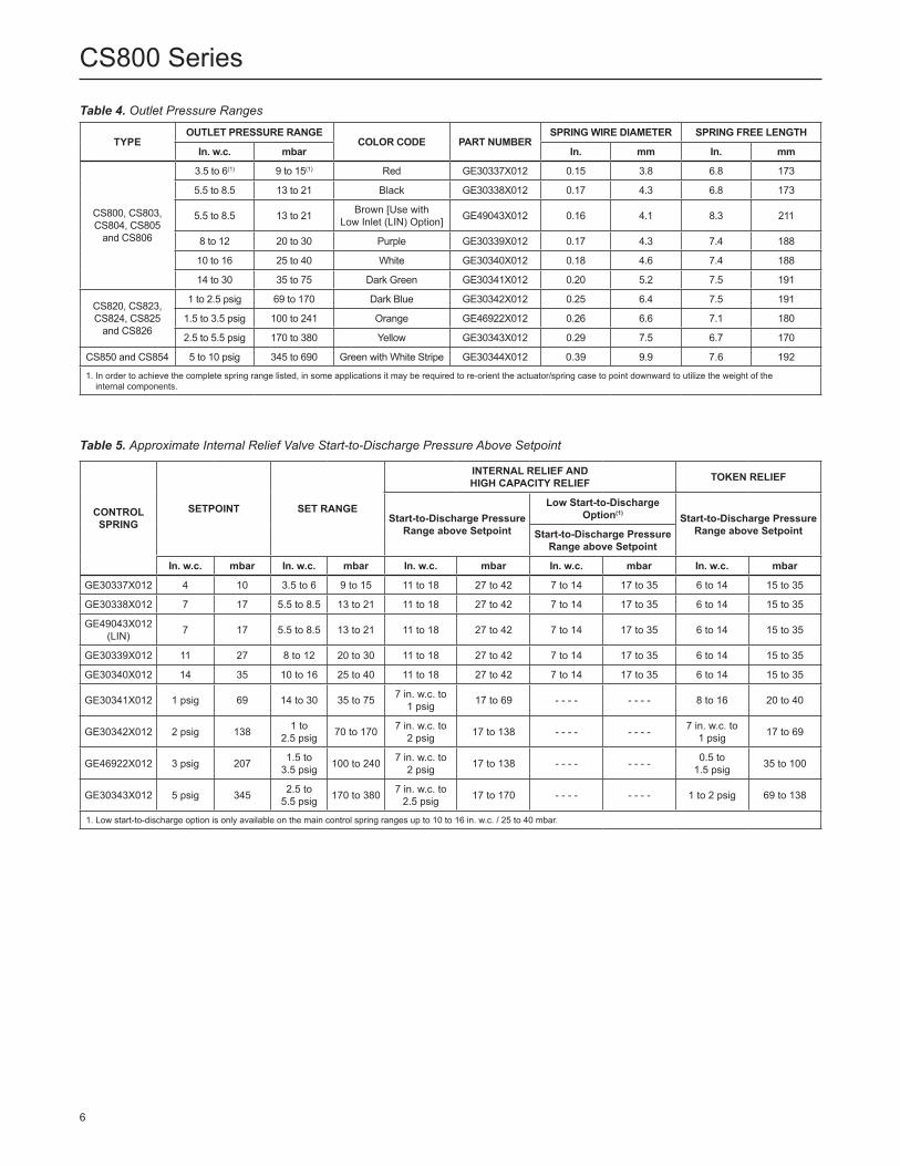
Table 5. Approximate Internal Relief Valve Start-to-Discharge Pressure Above Setpoint
Table 4. Outlet Pressure Ranges
TYPEOUTLET PRESSURE RANGE
COLOR CODE PART NUMBERSPRING WIRE DIAMETER SPRING FREE LENGTH
In. w.c. mbar In. mm In. mm
CS800, CS803, CS804, CS805
and CS806
3.5 to 6(1) 9 to 15(1) Red GE30337X012 0.15 3.8 6.8 173
5.5 to 8.5 13 to 21 Black GE30338X012 0.17 4.3 6.8 173
5.5 to 8.5 13 to 21 Brown [Use with Low Inlet (LIN) Option] GE49043X012 0.16 4.1 8.3 211
8 to 12 20 to 30 Purple GE30339X012 0.17 4.3 7.4 188
10 to 16 25 to 40 White GE30340X012 0.18 4.6 7.4 188
14 to 30 35 to 75 Dark Green GE30341X012 0.20 5.2 7.5 191
CS820, CS823, CS824, CS825
and CS826
1 to 2.5 psig 69 to 170 Dark Blue GE30342X012 0.25 6.4 7.5 191
1.5 to 3.5 psig 100 to 241 Orange GE46922X012 0.26 6.6 7.1 180
2.5 to 5.5 psig 170 to 380 Yellow GE30343X012 0.29 7.5 6.7 170
CS850 and CS854 5 to 10 psig 345 to 690 Green with White Stripe GE30344X012 0.39 9.9 7.6 192
1. In order to achieve the complete spring range listed, in some applications it may be required to re-orient the actuator/spring case to point downward to utilize the weight of the internal components.
CONTROL SPRING
SETPOINT SET RANGE
INTERNAL RELIEF AND HIGH CAPACITY RELIEF TOKEN RELIEF
Start-to-Discharge Pressure Range above Setpoint
Low Start-to-Discharge Option(1) Start-to-Discharge Pressure
Range above SetpointStart-to-Discharge Pressure Range above Setpoint
In. w.c. mbar In. w.c. mbar In. w.c. mbar In. w.c. mbar In. w.c. mbar
GE30337X012 4 10 3.5 to 6 9 to 15 11 to 18 27 to 42 7 to 14 17 to 35 6 to 14 15 to 35
GE30338X012 7 17 5.5 to 8.5 13 to 21 11 to 18 27 to 42 7 to 14 17 to 35 6 to 14 15 to 35
GE49043X012 (LIN) 7 17 5.5 to 8.5 13 to 21 11 to 18 27 to 42 7 to 14 17 to 35 6 to 14 15 to 35
GE30339X012 11 27 8 to 12 20 to 30 11 to 18 27 to 42 7 to 14 17 to 35 6 to 14 15 to 35
GE30340X012 14 35 10 to 16 25 to 40 11 to 18 27 to 42 7 to 14 17 to 35 6 to 14 15 to 35
GE30341X012 1 psig 69 14 to 30 35 to 75 7 in. w.c. to 1 psig 17 to 69 - - - - - - - - 8 to 16 20 to 40
GE30342X012 2 psig 138 1 to 2.5 psig 70 to 170 7 in. w.c. to
2 psig 17 to 138 - - - - - - - - 7 in. w.c. to 1 psig 17 to 69
GE46922X012 3 psig 207 1.5 to 3.5 psig 100 to 240 7 in. w.c. to
2 psig 17 to 138 - - - - - - - - 0.5 to 1.5 psig 35 to 100
GE30343X012 5 psig 345 2.5 to 5.5 psig 170 to 380 7 in. w.c. to
2.5 psig 17 to 170 - - - - - - - - 1 to 2 psig 69 to 138
1. Low start-to-discharge option is only available on the main control spring ranges up to 10 to 16 in. w.c. / 25 to 40 mbar.
6
CS800 Series

Table 6. Secondary Seat™ Outlet Pressures
CONTROL SPRING SPRING RANGE SETPOINT
SECONDARY SEAT SHUTOFF PRESSURE(2)
(TYPES CS805 AND CS825)DOWNSTREAM BUILD-UP PRESSURE(1)(2)(3)
(TYPES CS806 AND CS826)
Up to 1/2 in. / 13 mm Orifice Size
Up to 7/8 in. / 22 mm Orifice Size
Up to 1/2 in. / 13 mm Orifice Size
Up to 7/8 in. / 22 mm Orifice Size
Color In. w.c. mbar In. w.c. mbar In. w.c. mbar In. w.c. mbar In. w.c. mbar In. w.c. mbar
Black 5.5 to 8.5 13 to 21 7 17 11 27 12 30 25 62 23 57
Brown (LIN) 5.5 to 8.5 13 to 21 7 17 11 27 12 30 25 62 23 57
White Stripe 10 to 16 25 to 40 14 35 19 47 20 50 36 89 33 81
Dark Green 14 to 30 35 to 75 1 psig 69 1.2 psig 83 1.3 psig 90 2.1 psig 145 2 psig 138
Dark Blue 1 to 2.5 psig 69 to 170 2 psig 140 2.6 psig 179 2.6 psig 179 3.8 psig 262 3.7 psig 255
Yellow 2.5 to 5.5 psig
170 to 380 5 psig 345 6.3 psig 434 6.3 psig 434 7.4 psig 510 8.2 psig 565
1. Downstream pressure buildup with Secondary Seat fixed bleed in operation and regulator relief valve relieving to atmosphere.2. Outlet pressure values listed are at maximum operating inlet pressure rating per orifice.3. If the outlet pressure rises above setpoint exceeding the pressure rating of the regulator, the internal parts must be inspected and replaced if damaged.
Table 7. Types CS803 and CS823 Regulator and Integral True-Monitor™ Outlet Pressure Ranges without Token Relief
PRIMARY REGULATOR INTEGRAL TRUE-MONITOR
TypeSetpoint Spring Range
Spring ColorSetpoint Spring Range Spring
ColorIn. w.c. mbar In. w.c. mbar In. w.c. mbar In. w.c. mbar
CS803IN and CS803EN
4 10 3.5 to 6 9 to 15 Red14 35 12 to 21 30 to 52 Blue 21 52 18 to 30 45 to 75 Green
1 psig 69 26 to 40 65 to 99 Orange
7 17 5.5 to 8.5 13 to 21 Black14 35 12 to 21 30 to 52 Blue 21 52 18 to 30 45 to 75 Green
1 psig 69 26 to 40 65 to 99 Orange
7 17 5.5 to 8.5 13 to 21 Brown (LIN)14 35 12 to 21 30 to 52 Blue 21 52 18 to 30 45 to 75 Green
1 psig 69 26 to 40 65 to 99 Orange
11 27 8 to 12 20 to 30 Purple21 52 18 to 30 45 to 75 Green
1 psig 69 26 to 40 65 to 99 Orange 1.5 psig 103 1.4 to 2.9 psig 97 to 200 Black
14 35 10 to 16 25 to 40 White21 52 18 to 30 45 to 75 Green
1 psig 69 26 to 40 65 to 99 Orange 1.5 psig 103 1.4 to 2.9 psig 97 to 200 Black
1 psig 69 14 to 30 35 to 75 Dark Green1.5 psig 103 1.4 to 2.9 psig 97 to 200 Black2 psig 138 1.4 to 2.9 psig 97 to 200 Black
3.5 psig 241 2.6 to 3.7 psig 179 to 255 Purple
CS823IN and CS823EN
2 psig 138 1 to 2.5 psig 69 to 170 Dark Blue2.5 psig 172 1.4 to 2.9 psig 97 to 200 Black3 psig 207 2.6 to 3.7 psig 179 to 255 Purple5 psig 345 3.6 to 6 psig 248 to 414 Dark Blue
3 psig 207 1.5 to 3.5 psig 100 to 241 Orange3.5 psig 241 2.6 to 3.7 psig 179 to 255 Purple4 psig 276 3.6 to 6 psig 248 to 414 Dark Blue6 psig 414 5.1 to 7.5 psig 352 to 517 Red
5 psig 345 2.5 to 5.5 psig 170 to 380 Yellow6 psig 414 5.1 to 7.5 psig 352 to 517 Red 7 psig 483 5.1 to 7.5 psig 352 to 517 Red
7.5 psig 517 5.1 to 7.5 psig 352 to 517 Red
7
CS800 Series
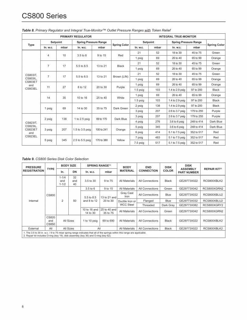
Table 9. CS800 Series Disk Color Selection
PRESSURE REGISTRATION TYPE
BODY SIZE SPRING RANGE(1)BODY
MATERIALEND
CONNECTIONDISK
COLOR
DISK ASSEMBLY
PART NUMBERREPAIR KIT(2)
In. DN In. w.c. mbar
Internal
CS800
1-1/4 and
1-1/2
32 and 40
3.5 to 30 9 to 75 All Materials All Connections Black GE29773X022 RCS800XBLK2
2 50
3.5 to 6 9 to 15 All Materials All Connections Green GE29773X042 RCS800XGRN2
5.5 to 8.5 and 8 to 12
13 to 21 and 20 to 30
Gray Cast Iron All Connections Blue GE29773X032 RCS800XBLU2
Ductile Iron or WCC Steel
Flanged Blue GE29773X032 RCS800XBLU2Threaded Dark Gray GE29773X082 RCS800XGRY2
10 to 16 and 14 to 30
25 to 40 and 35 to 75 All Materials All Connections Green GE29773X042 RCS800XGRN2
CS820 and
CS850All Sizes 1 to 10 psig 69 to 690 All Materials All Connections Black GE29773X022 RCS800XBLK2
External All All Sizes All All Materials All Connections Black GE29773X022 RCS800XBLK21. The 3.5 to 30 in. w.c. / 9 to 75 mbar spring range indicates that all of the springs within this range are applicable.2. Repair kit includes O-ring (key 19), disk assembly (key 36) and O-ring (key 62).
Table 8. Primary Regulator and Integral True-Monitor™ Outlet Pressure Ranges with Token Relief
PRIMARY REGULATOR INTEGRAL TRUE-MONITOR
TypeSetpoint Spring Pressure Range
Spring ColorSetpoint Spring Pressure Range
Spring ColorIn. w.c. mbar In. w.c. mbar In. w.c. mbar In. w.c. mbar
CS803IT, CS803IL, CS803ET
and CS803EL
4 10 3.5 to 6 9 to 15 Red21 52 18 to 30 45 to 75 Green
1 psig 69 26 to 40 65 to 99 Orange
7 17 5.5 to 8.5 13 to 21 Black21 52 18 to 30 45 to 75 Green
1 psig 69 26 to 40 65 to 99 Orange
7 17 5.5 to 8.5 13 to 21 Brown (LIN)21 52 18 to 30 45 to 75 Green
1 psig 69 26 to 40 65 to 99 Orange
11 27 8 to 12 20 to 30 Purple1 psig 69 26 to 40 65 to 99 Orange
1.5 psig 103 1.4 to 2.9 psig 97 to 200 Black
14 35 10 to 16 25 to 40 White1 psig 69 26 to 40 65 to 99 Orange
1.5 psig 103 1.4 to 2.9 psig 97 to 200 Black
1 psig 69 14 to 30 35 to 75 Dark Green2 psig 138 1.4 to 2.9 psig 97 to 200 Black
3 psig 207 2.6 to 3.7 psig 179 to 255 Purple
CS823IT, CS823IL, CS823ET
and CS823EL
2 psig 138 1 to 2.5 psig 69 to 170 Dark Blue3 psig 207 2.6 to 3.7 psig 179 to 255 Purple
4 psig 276 3.6 to 6 psig 248 to 414 Dark Blue
3 psig 207 1.5 to 3.5 psig 100 to 241 Orange5 psig 345 3.6 to 6 psig 248 to 414 Dark Blue
6 psig 414 5.1 to 7.5 psig 352 to 517 Red
5 psig 345 2.5 to 5.5 psig 170 to 380 Yellow7 psig 483 5.1 to 7.5 psig 352 to 517 Red
7.5 psig 517 5.1 to 7.5 psig 352 to 517 Red
8
CS800 Series

Table 10. CS803 and CS804 Series Disk Color Selection
PRESSURE REGISTRATION TYPE
BODY SIZE SPRING RANGE(1)BODY
MATERIALEND
CONNECTIONDISK
COLOR
DISK ASSEMBLY
PART NUMBERREPAIR KIT(2)
In. DN In. w.c. mbar
Internal
CS803 and
CS804
1-1/2 40 3.5 to 30 9 to 75 All Materials All Connections Black GE29773X022 RCS800XBLK2
2 50
3.5 to 6 9 to 15 All Materials All Connections Green GE29773X042 RCS800XGRN2
5.5 to 8.5 and 8 to 12
13 to 21 and 20 to 30
Ductile Iron or WCC Steel
Flanged Blue GE29773X032 RCS800XBLU2Threaded Dark Gray GE29773X082 RCS800XGRY2
Gray Cast Iron All Connections Blue GE29773X032 RCS800XBLU2
10 to 16 and 14 to 30
25 to 40 and 35 to 75 All Materials All Connections Green GE29773X042 RCS800XGRN2
CS823, CS824
and CS854
All Sizes 1 to 10 psig 69 to 690 All Materials All Connections Black GE29773X022 RCS800XBLK2
External All All Sizes All All Materials All Connections Black GE29773X022 RCS800XBLK21. The 3.5 to 30 in. w.c. / 9 to 75 mbar spring range indicates that all of the springs within this range are applicable.2. Repair kit includes O-ring (key 19), disk assembly (key 36) and O-ring (key 62).
Table 11. CS805 and CS806 Series Disk Color Selection
PRESSURE REGISTRATION TYPE
BODY SIZE SPRING RANGE(1)BODY
MATERIALEND
CONNECTIONDISK
COLOR
DISK ASSEMBLY
PART NUMBERREPAIR KIT(3)
In. DN In. w.c. mbar
Internal
CS805 and
CS806
1-1/4 32
3.5 to 30 9 to 75 Gray Cast Iron All Connections
Yellow/White Dot GE29773X062 RCS800XYEL2
1-1/2 40 Green/White Dot GE29773X092 RCS800XGR22
2 50 White/White Dot(2) GE29773X052 RCS800XWHT2
CS825 and
CS826All Sizes 1 to 5.5 psig 69 to 380 Gray Cast
Iron All Connections Yellow/White Dot GE29773X062 RCS800XYEL2
External All All Sizes All All Materials All Connections Black GE29773X022 RCS800XBLK21. The 3.5 to 30 in. w.c. / 9 to 75 mbar spring range indicates that all of the springs within this range are applicable.2. White/White Dot disk requires the open end to be directed downstream with the direction of flow.3. Repair kit includes O-ring (key 19), disk assembly (key 36) and O-ring (key 62).
Table 12. Regulator and Slam-Shut Overpressure Shutoff (OPSO) Pressure Ranges
REGULATORSLAM-SHUT DEVICE
Over Pressure Shut-off (OPSO)
TypeFactory Setpoint Spring Range Factory Setpoint(1) Spring Range(2) Spring Part Number
and ColorIn. w.c. mbar In. w.c. mbar In. w.c. mbar In. w.c. mbar
CS804
4 10 3.5 to 6 9 to 15 19 4712 to 25 30 to 60 GF02168X012 / Brown
7 17 5.5 to 8.5 14 to 21 22 55
7 (optional) 17 (optional) 5.5 to 8.5 14 to 2125 62 16 to 44 40 to 110 GF02169X012 / Red
11 27 8 to 12 20 to 30
14 35 10 to 16 25 to 40 30 75 24 to 78 60 to 190 GF02170X012 / Orange
14 (optional) 35 (optional) 10 to 16 25 to 40 2 psig 138 1.4 to 4.1 psig 97 to 283 GF02171X012 / Pink
1 psig 69 14 to 30 35 to 75 2 psig 138
CS824
2 psig 138 1 to 2.5 psig 69 to 170 3.5 psig 2412 to 7.3 psig 138 to 503 GF02172X012 / Green
3 psig 207 1.5 to 3.5 psig 100 to 241 5 psig 345
5 psig 345 2.5 to 5.5 psig 170 to 380 7 psig 483 3.2 to
8.5 psig 221 to 586 GF02173X012 / Silver
CS854 7 psig 483 5 to 10 psig 345 to 690 9 psig 621 5.8 to 13 psig 400 to 896 GF04353X012 / Yellow
1. For units equipped with Token Relief, if Non-Factory Slam-shut OPSO setpoints are specified, they must be higher than the Token Relief Start-to-Discharge values provided in Table 5.2. If Non-Factory OPSO setpoints are specified, the allowable OPSO setpoint cannot exceed the maximum of 3 psig / 207 mbar above the regulator setpoint in order to ensure no internal
parts damage from overpressure.
9
CS800 Series
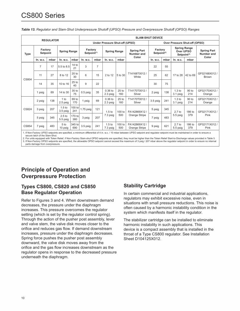
Principle of Operation and Overpressure Protection
Types CS800, CS820 and CS850 Base Regulator OperationRefer to Figures 3 and 4. When downstream demand decreases, the pressure under the diaphragm increases. This pressure overcomes the regulator setting (which is set by the regulator control spring). Through the action of the pusher post assembly, lever and valve stem, the valve disk moves closer to the orifice and reduces gas flow. If demand downstream increases, pressure under the diaphragm decreases. Spring force pushes the pusher post assembly downward, the valve disk moves away from the orifice and the gas flow increases downstream as the regulator opens in response to the decreased pressure underneath the diaphragm.
Stability CartridgeIn certain commercial and industrial applications, regulators may exhibit excessive noise, even in situations with small pressure reductions. This noise is often caused by a harmonic instability condition in the system which manifests itself in the regulator.
The stabilizer cartridge can be installed to eliminate harmonic instability in such applications. This device is a compact assembly that is installed in the throat of a Type CS800 regulator. See Installation Sheet D104125X012.
Table 13. Regulator and Slam-Shut Underpressure Shutoff (UPSO) Pressure and Overpressure Shutoff (OPSO) Ranges
REGULATORSLAM-SHUT DEVICE
Under Pressure Shut-off (UPSO) Over Pressure Shut-off (OPSO)
TypeFactory Setpoint Spring Range Factory
Setpoint(1) Spring Range Spring Part Number and
Color
Factory Setpoint(2)
Spring RangeOver UPSO Setpoint(3)
Spring Part Number and
ColorIn. w.c. mbar In. w.c. mbar In. w.c. mbar In. w.c. mbar In. w.c. mbar In. w.c. mbar
CS804
7 17 5.5 to 8.5 14 to 21 3 7
2 to 12 5 to 30 T14168T0012 / White
22 55
17 to 28 42 to 69 GF02168X012 / Brown11 27 8 to 12 20 to
30 6 15 25 62
14 35 10 to 16 25 to 40 9 22 30 75
1 psig 69 14 to 30 35 to 75 0.5 psig 35 0.36 to
2.3 psig25 to 160
T14170T0012 / Silver 2 psig 138 1.3 to
3.1 psig90 to 214
GF02170X012 / Orange
CS824
2 psig 138 1 to 2.5 psig
69 to 170 1 psig 69 0.36 to
2.3 psig25 to 160
T14170T0012 / Silver 3.5 psig 241 1.3 to
3.1 psig90 to 214
GF02170X012 / Orange
3 psig 207 1.5 to 3.5 psig
100 to 241 1.75 psig 121
1.5 to 7.3 psig
100 to 500
FA142869X12 / Orange Stripe
5 psig 3452.7 to
5.5 psig186 to 379
GF02171X012 / Pink
5 psig 345 2.5 to 5.5 psig
170 to 380 3 psig 207 7 psig 483
CS854 7 psig 483 5 to 10 psig
345 to 690 3.5 psig 241 1.5 to
7.3 psig100 to 500
FA142869X12 / Orange Stripe 9 psig 621 2.7 to
5.5 psig186 to 379
GF02171X012 / Pink
1. If Non-Factory UPSO setpoints are specified, a minimum differential of 4 in. w.c. / 10 mbar between UPSO setpoint and regulator setpoint must be maintained in order to ensure a secure latch of the Slam-Shut.
2. For units equipped with Token Relief, if Non-Factory Slam-shut OPSO setpoints are specified, they must be higher than the Token Relief Start-to-Discharge values provided in Table 5.3. If Non-Factory OPSO setpoints are specified, the allowable OPSO setpoint cannot exceed the maximum of 3 psig / 207 mbar above the regulator setpoint in order to ensure no internal
parts damage from overpressure.
10
CS800 Series

Figure 3. Type CS800IR Internally Registered Regulator with Internal Relief Operational Schematic
M1070
Figure 4. Type CS800EN Externally Registered Regulator Operational Schematic
M1069
INLET PRESSUREOUTLET PRESSUREATMOSPHERIC PRESSURE
INLET PRESSUREOUTLET PRESSUREATMOSPHERIC PRESSURE
LEVERVALVE STEM
REGULATOR DISK
REGULATOR ORIFICE
ADJUSTING SCREW
CONTROL SPRING
RELIEF VALVE STEM
RELIEF VALVE SPRING
PUSHER POST
DIAPHRAGM ASSEMBLY
PUSHER POST
LEVERVALVE STEM
REGULATOR DISK
REGULATOR ORIFICE
ADJUSTING SCREW
CONTROL SPRING
3/4 NPT CONTROL LINE CONNECTION
DIAPHRAGM ASSEMBLY
11
CS800 Series
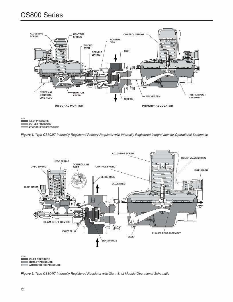
Figure 5. Type CS803IT Internally Registered Primary Regulator with Internally Registered Integral Monitor Operational Schematic
M1074
INLET PRESSUREOUTLET PRESSUREATMOSPHERIC PRESSURE
Figure 6. Type CS804IT Internally Registered Regulator with Slam-Shut Module Operational Schematic
ADJUSTING SCREW
EXTERNAL CONTROL LINE PLUG
CONTROL SPRING
MONITOR LEVER
GUIDEDSTEM
OPENING SPRING
MONITOR DISK
DISK
CONTROL SPRING
PUSHER POST ASSEMBLYVALVE STEM
ORIFICE
INTEGRAL MONITOR PRIMARY REGULATOR
Type CS800EN Regulator
M10
86
January 2008 Type CS800EN
INLET PRESSUREOUTLET PRESSUREATMOSPHERIC PRESSURE
INLET PRESSUREOUTLET PRESSUREATMOSPHERIC PRESSURE
M1075
VALVE STEM
DIAPHRAGM
RELIEF VALVE SPRING
PUSHER POST ASSEMBLY
ADJUSTING SCREW
CONTROL SPRING
LEVERSEAT/ORIFICE
SLAM SHUT DEVICE
VALVE PLUG
UPSO SPRINGCONTROL LINE PORT
DIAPHRAGM
OPSO SPRING
SENSE TUBE
12
CS800 Series

Figure 7. CS805 Series with Secondary Seat™ Protection
M1072
M1072
4
CP200 Series with Secondary SeatTM Protection
CONTROL SPRING
RELIEF V LVE STEM
VALVE STEM
SECONDARY SEAT DETAIL
SECONDARY SEAT DETAILED VIEW
NORMAL OPERATION NORMAL LOCKUP DEBRIS OBSTRUCTINGLOCKUP
TYPE CS805 SECONDARY SEAT LOCK-UP
TYPE CS806 SECONDARY SEAT WITH
CONTROLLED BLEED
METALLIC SECONDARY ORIFICE SEATING
SURFACEPRIMARY DISK
SECONDARY SEATING SURFACE
PRIMARY ORIFICE SEATING SURFACE
ELASTOMERIC SECONDARY SEATING SURFACE
INLET PRESSUREOUTLET PRESSUREATMOSPHERIC PRESSURE
INLET PRESSUREOUTLET PRESSUREATMOSPHERIC PRESSURE
PUSHER POST
LEVER
VALVE STEM
REGULATOR DISK
REGULATOR ORIFICE
ADJUSTING SCREW
CONTROL SPRING
SECONDARY SEAT DETAIL
RELIEF VALVE STEM
RELIEF VALVE SPRING
DIAPHRAGM ASSEMBLY
13
CS800 Series

Relief Operation
Internal Relief “R”Type numbers with the “R” suffix, e.g., Type CS800IR, provide internal relief discharge through the diaphragm assembly (see Figure 3) to minimize overpressure. Any outlet pressure above the start- to- discharge point of the non-adjustable relief spring (see Table 5) moves the diaphragm off the relief seat, allowing excess pressure to discharge through the vent. If conditions should exist that prevent normal operation of the regulator or internal relief valve, the relief valve stem acts as a secondary travel stop contacting the underside of the closing cap and stopping the upward travel of the relief seat. Since the diaphragm continues to rise as downstream pressure builds, the diaphragm lifts off of the relief seat to provide relief operation. This secondary travel stop for internal relief is not available on token relieving units. Units with internal relief valve have 1 NPT vent size. See Figures 9, 11, 13, 15, 17 and 19 for relief capacity.
High-Capacity Internal Relief “Q”Type numbers with the “Q” suffix, e.g., Type CS800IQ, provide high capacity relief discharge across the diaphragm assembly to minimize overpressure. Any outlet pressure above the start-to-discharge point of the non-adjustable relief spring (see Table 5) moves the diaphragm off the relief seat, allowing excess pressure to discharge through the vent. If emergency conditions should exist that prevent normal operation of the regulator or internal relief valve, the relief valve stem acts as a secondary travel stop contacting the underside of the closing cap and stopping the upward
travel of the relief seat. Since the diaphragm continues to rise as downstream pressure builds, the diaphragm lifts off of the relief seat to provide relief operation. The secondary travel stop for internal relief is not available on token relieving units. Units with high capacity internal relief valve have 2-1/2 NPT vent size. See Figures 10, 12, 14, 16, 18 and 20 for relief capacity. Contact Factory if using stabilizer cartridge for data.
Token Relief “T” and Low Flow Token Relief “L”Type numbers with the “T” or “L” suffix, e.g., Types CS800IT and CS800IL provide a low capacity/token relief. Token relief provides relief from minor overpressure caused by nicks or dents on the orifice or by thermal expansion of gas in the downstream line. Token relief also provides a token or signal, in the form of odor, that an overpressure situation is occurring. Start-to-discharge values for Token reliefs are found in Table 5. Maximum discharge capacities for Token reliefs are found in Figure 8.
Types CS803 and CS823 Integral True-Monitor™ OperationTypes CS803 and CS823 combine the operation of a conventional two-regulator wide-open monitor set into one body, see Figure 5. The Integral True-Monitor is installed on the inlet side of the body and serves to control downstream pressure in the situation where the Primary regulator can no longer regulate downstream pressure. During normal operation the True-Monitor is in a wide-open state as its setpoint is set higher than the primary regulator. See Tables 7 and 8 for guidance regarding the setpoints of the regulator and associated Integral Monitor sets. If the downstream pressure
Figure 8. Maximum Discharge Capacity for Token and Low Flow Token Relief
REG
ULA
TOR
SET
POIN
T, p
sig
/ bar
Discharge Capacity in SCFH / Nm3/h at Maximum Operating Outlet(3 psi / 0.21 bar setpoint) (Specific Gravity Gas = 0.6)
6 / 0.41
150 / 4.02
200 / 5.36
250 / 6.7
300 / 8.04
350 / 9.38
400 / 10.72
450 / 12.06
5.5 / 0.38
4.5 / 0.31
2.5 / 0.17
3.5 / 0.24
1.5 / 0.10
0.5 / 0.03
5 / 0.34
4 / 0.28
3 / 0.21
2 / 0.14
1 / 0.69
0 REG
ULA
TOR
SET
POIN
T, p
sig
/ bar
Discharge Capacity in SCFH / Nm3/h at Maximum Operating Outlet(3 psi / 0.21 bar setpoint) (Specific Gravity Gas = 0.6)
6 / 0.41
8 / 0.214
10 / 0.268
12 / 0.322
14 / 0.375
16 / 0.429
20 / 0.536
22 / 0.59
24 / 0.643
18 / 0.482
26 / 0.697
5.5 / 0.38
4.5 / 0.31
2.5 / 0.17
3.5 / 0.24
1.5 / 0.10
0.5 / 0.03
5 / 0.34
4 / 0.28
3 / 0.21
2 / 0.14
1 / 0.69
0
Maximum Discharge Capacity for Token Relief Maximum Discharge Capacity for Low Flow Token Relief
14
CS800 Series

should rise to the setpoint of the True-Monitor due to loss of pressure control by the primary regulator, the monitor will assume control and regulate flow to the downstream system. Internal and external downstream pressure registration are available. External pressure registration requires a downstream sensing line. See the Type TM600 Instruction Manual for additional details of operation.If a Token relief is present, the token relief will relieve a small amount of gas to the atmosphere as an indication that the Integral Monitor is controlling the downstream pressure.
Types CS804, CS824 and CS854 Slam-Shut OperationThe Type VSX8 Slam-shut module on the CS804 Series regulators is a fast acting shutoff device that provides overpressure (OPSO) or overpressure and underpressure (OPSO/UPSO) protection by completely shutting off the flow of gas to the downstream system. See Tables 12 and 13 for guidance regarding the typical setpoint of the regulator and associated OPSO and UPSO sets. The Type VSX8’s actions are independent of the CS804 Series regulator and of variations to the inlet pressure. The Type VSX8 provides the option of internal or external downstream pressure registration. External registration requires a downstream sensing line. The Type VSX8 shutoff disk is normally in the open (reset) position, see Figure 6. If the downstream pressure below the slam-shut diaphragm increases (or decreases) until it reaches the slam-shut setpoint, this diaphragm moves upward (or downward) to release the trip mechanism which allows the spring force on the stem to push the disk against the seat, shutting off all gas flow. To reset the slam-shut after gas has been shutoff, refer to Type VSX8 Instruction Manual (D103127X012) for additional details.
Note
In order for the Underpressure Shutoff (UPSO) of any slam-shut to be triggered, the downstream pipe pressure must drop below the UPSO setpoint. In the case of a downstream line break, numerous factors can prevent the downstream pipe pressure from decreasing below the slam-shut UPSO setpoint. These factors include
the distance of pipe to the break, the diameter of the pipe, size of the break and the number of restrictions, such as valves, elbows and bends, downstream of the regulator and/or slam-shut device. Due to these factors additional protections should be installed to stop flow in the event of a line break.
Types CS805 and CS825 with Secondary Seat™ Protection
NoteTypes CS805 and CS825 regulators do not have any means to alert when the Secondary Seat operates at lockup. Therefore, it is recommended that Internal relief or high-capacity relief are also selected or the addition of some other method of overpressure protection be added in the downstream system as discussed in the Overpressure Protection section.
Refer to Figure 7. The Type CS805 provides Secondary Seat Protection. As downstream demand decreases and downstream pressure rises to the regulator pressure lockup value, the regulator will lockup. If, however, damage has occurred to the primary disk, to the primary orifice seating surface or debris has become lodged between the primary disk and primary orifice, the outlet pressure will continue to rise. This additional pressure causes the primary disk to apply additional force to the orifice seating surface, which causes the Secondary seating surface to move toward the Secondary disk or sealing surface. If downstream demand decreases to zero, then the secondary seating surface will contact the sealing surface to provide lockup. See Table 6 for Secondary Seat shutoff above setpoint.
Types CS806 and CS826 Secondary Seat Protection with Bleed The Types CS806 and CS826 provides small bleed to the downstream system as an indication that the Secondary Seat is providing lock-up. In the event that the primary orifice and disk cannot provide lockup, the secondary seating surface will move into contact with a metal disk. This metal to metal interface, combined with a small drilled bleed hole, will allow a small amount of gas to bleed downstream thereby
15
CS800 Series

increasing outlet pressure until the internal relief valve begins to discharge gas to the atmosphere. The odor of this discharged gas provides an indication that the regulator is relying on the Secondary Seat for overpressure protection. See Table 6 for Secondary Seat maximum downstream buildup.
Secondary Seat Protection Limitations
Note
Overpresssure conditions can occur in the downstream piping when the Secondary Seat Protection is installed. The Secondary Seat Protection serves only as a backup to the primary seat for lockup. Refer to the sections on Overpressure Protection and Maintenance.
Secondary Seat Protection does not provide additional overpressure protection in the event the secondary seat or disk is damaged by debris or contamination in the pipeline or from conditions that would cause the regulator to go wide-open.
InstallationThe CS800 Series regulators may be installed in any position. However, the spring case vent should be pointed downward. If gas escaping through the CS800 Series internal relief valve could constitute a hazard, the spring case vent must be piped to a location where escaping gas will not be hazardous. If the vented gas will be piped to another location, use obstruction-free tubing or piping at least equal in size to the vent; protect the end of the vent pipe from anything that might clog it. Regulators with External Registration require the use of an external control line.
Non-Relieving “N”Type numbers with the “N” suffix, e.g., Type CS800IN, do not provide internal relief discharge through the diaphragm assembly.The CS800 Series regulators have outlet pressure ratings that are lower than their inlet pressure ratings. A pressure relieving or pressure limiting device is needed if the application inlet pressure can exceed the outlet pressure rating and the regulator is not equipped with internal relief, high capacity relief, Integral True-Monitor™ Protection or Secondary Seat™ Protection.
Note
Overpressuring any portion of a regulator or associated equipment may cause personal injury, leakage or property damage due to bursting of pressure-containing parts or explosion of accumulated gas. Provide appropriate pressure relieving or pressure limiting devices to ensure that the limits in the specifications section are not exceeded. Regulator operation within ratings does not prevent the possibility of damage from external sources or from debris in the pipeline.
Downstream Control Line ConnectionA CS800 Series regulator with an EN, ET or ER in the type number has a blocked throat, an O-ring stem seal and a 3/4 NPT control line tapping in the lower diaphragm casing, see Figure 4. A regulator with a downstream control line is used for monitoring installations or other applications where there is other equipment installed between the regulator and the pressure control point. The O-ring stem seal helps separate body pressure from diaphragm case pressure on monitor installations where leakage cannot be tolerated.
Capacity InformationTables 14 through 66 provide natural gas regulating capacities at selected inlet pressures, outlet pressure settings and body outlet sizes. Flows are in SCFH (60°F and 14.7 psia) and Nm3/h (0°C and 1.01,325 bar) of 0.6 specific gravity natural gas. To determine equivalent capacities for air, propane, butane or nitrogen, multiply the capacity number in the tables by the following appropriate conversion factor: 0.775 for air, 0.628 for propane, 0.548 for butane or 0.789 for nitrogen. For gases of other specific gravities, multiply the given capacity by 0.775 and divide by the square root of the appropriate specific gravity.
16
CS800 Series
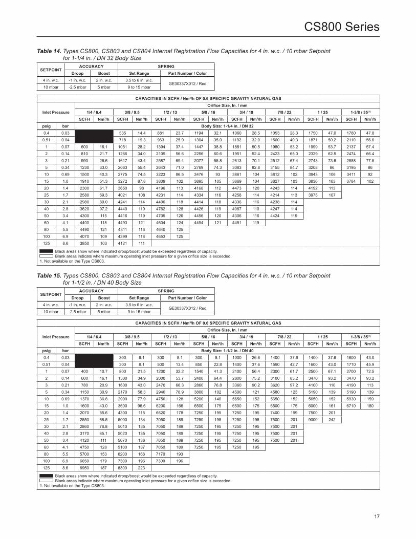
Table 14. Types CS800, CS803 and CS804 Internal Registration Flow Capacities for 4 in. w.c. / 10 mbar Setpoint for 1-1/4 in. / DN 32 Body Size
SETPOINTACCURACY SPRING
Droop Boost Set Range Part Number / Color4 in. w.c. -1 in. w.c. 2 in. w.c. 3.5 to 6 in. w.c.
GE30337X012 / Red10 mbar -2.5 mbar 5 mbar 9 to 15 mbar
CAPACITIES IN SCFH / Nm3/h OF 0.6 SPECIFIC GRAVITY NATURAL GAS
Inlet PressureOrifice Size, In. / mm
1/4 / 6.4 3/8 / 9.5 1/2 / 13 5/8 / 16 3/4 / 19 7/8 / 22 1 / 25 1-3/8 / 35(1)
SCFH Nm3/h SCFH Nm3/h SCFH Nm3/h SCFH Nm3/h SCFH Nm3/h SCFH Nm3/h SCFH Nm3/h SCFH Nm3/hpsig bar Body Size: 1-1/4 in. / DN 320.4 0.03 0.0 535 14.4 881 23.7 1194 32.1 1060 28.5 1053 28.3 1750 47.0 1780 47.8
0.51 0.04 0.0 718 19.3 963 25.9 1304 35.0 1192 32.0 1500 40.3 1871 50.2 2110 56.61 0.07 600 16.1 1051 28.2 1394 37.4 1447 38.8 1881 50.5 1980 53.2 1999 53.7 2137 57.42 0.14 810 21.7 1266 34.0 2109 56.6 2256 60.6 1951 52.4 2423 65.0 2329 62.5 2474 66.43 0.21 990 26.6 1617 43.4 2587 69.4 2077 55.8 2613 70.1 2512 67.4 2743 73.6 2888 77.55 0.34 1230 33.0 2063 55.4 2643 71.0 2769 74.3 3083 82.8 3155 84.7 3208 86 3195 8610 0.69 1500 40.3 2775 74.5 3223 86.5 3476 93 3861 104 3812 102 3943 106 3411 9215 1.0 1910 51.3 3272 87.8 3809 102 3895 105 3869 104 3827 103 3836 103 3784 10220 1.4 2300 61.7 3650 98 4196 113 4168 112 4473 120 4243 114 4192 11325 1.7 2580 69.3 4021 108 4231 114 4334 116 4258 114 4214 113 3975 10730 2.1 2980 80.0 4241 114 4406 118 4414 118 4336 116 4238 11440 2.8 3620 97.2 4440 119 4762 128 4426 119 4087 110 4247 11450 3.4 4300 115 4416 119 4705 126 4456 120 4306 116 4424 11960 4.1 4400 118 4493 121 4604 124 4494 121 4451 11980 5.5 4490 121 4311 116 4640 125
100 6.9 4070 109 4399 118 4653 125125 8.6 3850 103 4121 111
Black areas show where indicated droop/boost would be exceeded regardless of capacity. Blank areas indicate where maximum operating inlet pressure for a given orifice size is exceeded.1. Not available on the Type CS803.
Table 15. Types CS800, CS803 and CS804 Internal Registration Flow Capacities for 4 in. w.c. / 10 mbar Setpoint for 1-1/2 in. / DN 40 Body Size
SETPOINTACCURACY SPRING
Droop Boost Set Range Part Number / Color4 in. w.c. -1 in. w.c. 2 in. w.c. 3.5 to 6 in. w.c.
GE30337X012 / Red10 mbar -2.5 mbar 5 mbar 9 to 15 mbar
CAPACITIES IN SCFH / Nm3/h OF 0.6 SPECIFIC GRAVITY NATURAL GAS
Inlet PressureOrifice Size, In. / mm
1/4 / 6.4 3/8 / 9.5 1/2 / 13 5/8 / 16 3/4 / 19 7/8 / 22 1 / 25 1-3/8 / 35(1)
SCFH Nm3/h SCFH Nm3/h SCFH Nm3/h SCFH Nm3/h SCFH Nm3/h SCFH Nm3/h SCFH Nm3/h SCFH Nm3/hpsig bar Body Size: 1-1/2 in. / DN 400.4 0.03 300 8.1 300 8.1 300 8.1 1000 26.8 1400 37.6 1400 37.6 1600 43.00.51 0.04 300 8.1 500 13.4 850 22.8 1400 37.6 1590 42.7 1600 43.0 1710 45.9
1 0.07 400 10.7 800 21.5 1200 32.2 1540 41.3 2100 56.4 2300 61.7 2500 67.1 2700 72.52 0.14 600 16.1 1300 34.9 2000 53.7 2400 64.4 2800 75.2 3100 83.2 3470 93.2 3470 93.23 0.21 780 20.9 1600 43.0 2470 66.3 2860 76.8 3360 90.2 3620 97.2 4100 110 4190 1135 0.34 1150 30.9 2170 58.3 2940 78.9 3800 102 4500 121 4580 123 5190 139 5190 139
10 0.69 1370 36.8 2900 77.9 4750 128 5200 140 5650 152 5650 152 5650 152 5930 15915 1.0 1600 43.0 3600 96.6 6200 166 6500 175 6500 175 6500 175 6000 161 6710 18020 1.4 2070 55.6 4300 115 6620 178 7250 195 7250 195 7400 199 7500 20125 1.7 2550 68.5 5000 134 7050 189 7250 195 7250 195 7500 201 9000 24230 2.1 2860 76.8 5010 135 7050 189 7250 195 7250 195 7500 20140 2.8 3170 85.1 5020 135 7050 189 7250 195 7250 195 7500 20150 3.4 4120 111 5070 136 7050 189 7250 195 7250 195 7500 20160 4.1 4750 128 5100 137 7050 189 7250 195 7250 19580 5.5 5700 153 6200 166 7170 193
100 6.9 6650 179 7300 196 7300 196125 8.6 6950 187 8300 223
Black areas show where indicated droop/boost would be exceeded regardless of capacity. Blank areas indicate where maximum operating inlet pressure for a given orifice size is exceeded.1. Not available on the Type CS803.
17
CS800 Series

Table 17. Types CS800, CS803 and CS804 Internal Registration Flow Capacities for 7 in. w.c. / 17 mbar Setpoint for 1-1/4 in. / DN 32 Body Size
SETPOINTACCURACY SPRING
Droop Boost Set Range Part Number / Color7 in. w.c. -1 in. w.c. 2 in. w.c. 5.5 to 8.5 in. w.c.
GE30338X012 / Black17 mbar -2.5 mbar 5 mbar 13 to 21 mbar
CAPACITIES IN SCFH / Nm3/h OF 0.6 SPECIFIC GRAVITY NATURAL GAS
Inlet PressureOrifice Size, In. / mm
1/4 / 6.4 3/8 / 9.5 1/2 / 13 5/8 / 16 3/4 / 19 7/8 / 22 1 / 25 1-3/8 / 35(1)
SCFH Nm3/h SCFH Nm3/h SCFH Nm3/h SCFH Nm3/h SCFH Nm3/h SCFH Nm3/h SCFH Nm3/h SCFH Nm3/hpsig bar Body Size: 1-1/4 in. / DN 320.4 0.03 314 8.43 506 13.6 564 15.1 640 17.2 678 18.2 936 25.1 1073 28.8
0.51 0.04 396 10.6 501 13.4 789 21.2 815 21.9 871 23.4 1031 27.7 1214 32.61 0.07 429 11.5 586 15.7 850 22.8 977 26.2 1219 32.7 1341 36.0 1486 39.9 1532 41.12 0.14 631 16.9 818 22.0 1192 32.0 1423 38.2 1596 42.8 1696 45.5 1777 47.7 1947 52.33 0.21 746 20.0 1024 27.5 1449 38.9 1673 44.9 1828 49.1 2025 54.4 2105 56.5 2245 60.35 0.34 952 25.6 1163 31.2 1755 47.1 2110 56.6 2200 59.1 2390 64.2 2514 67.5 2518 67.6
10 0.69 1133 30.4 1918 51.5 2381 63.9 2778 74.6 2731 73.3 2993 80.3 3030 81.3 2942 79.015 1.0 1400 37.6 2428 65.2 2900 77.8 3159 84.8 2938 78.9 3246 87.1 3255 87.4 3116 83.620 1.4 1709 45.9 2792 74.9 3107 83.4 3406 91.4 3081 82.7 3232 86.8 3364 90.325 1.7 2041 54.8 2982 80.0 3260 87.5 3488 93.6 3289 88.3 3413 91.6 3332 89.430 2.1 2281 61.2 3312 88.9 3326 89.3 3573 95.9 3137 84.2 3408 91.540 2.8 2800 75.2 3569 95.8 3531 94.8 3632 97.5 3413 91.6 3414 91.650 3.4 3330 89.4 3574 95.9 3799 102.0 3559 95.5 3341 89.7 3410 91.560 4.1 3470 93.1 3405 91.4 3495 93.8 3515 94.4 3466 93.080 5.5 3498 93.9 3355 90.1 3469 93.1100 6.9 3459 92.9 3199 85.9 3489 93.7125 8.6 2149 57.7 2186 58.7
Black areas show where indicated droop/boost would be exceeded regardless of capacity. Blank areas indicate where maximum operating inlet pressure for a given orifice size is exceeded.1. Not available on the Type CS803.2. When stabilizer cartridge used with Types CS800, CS803 or CS804 could exhibit a 20% reduction in capacity for conditions marked.
Table 16. Types CS800, CS803 and CS804 Internal Registration Flow Capacities for 4 in. w.c. / 10 mbar Setpoint for 2 in / DN 50 Body Size
SETPOINTACCURACY SPRING
Droop Boost Set Range Part Number / Color4 in. w.c. -1 in. w.c. 2 in. w.c. 3.5 to 6 in. w.c.
GE30337X012 / Red10 mbar -2.5 mbar 5 mbar 9 to 15 mbar
CAPACITIES IN SCFH / Nm3/h OF 0.6 SPECIFIC GRAVITY NATURAL GAS
Inlet PressureOrifice Size, In. / mm
1/4 / 6.4 3/8 / 9.5 1/2 / 13 5/8 / 16 3/4 / 19 7/8 / 22 1 / 25 1-3/8 / 35(1)
SCFH Nm3/h SCFH Nm3/h SCFH Nm3/h SCFH Nm3/h SCFH Nm3/h SCFH Nm3/h SCFH Nm3/h SCFH Nm3/h
psig bar Body Size: 2 in. / DN 50
0.4 0.03 300 8.1 300 8.1 300 8.1 1170 31.4 1400 37.6 1600 43.0 1800 48.3
0.51 0.04 300 8.1 500 13.4 1000 26.8 1550 41.6 1900 51.0 2070 55.6 2400 64.4
1 0.07 400 10.7 900 24.2 1300 34.9 1760 47.2 1950 52.3 3000 80.5 2710 72.8 3800 102
2 0.14 600 16.1 1240 33.3 2070 55.6 2620 70.3 3930 106 5000 134 3450 92.6 5620 151
3 0.21 730 19.6 1530 41.1 2580 69.3 3540 95.0 4980 134 6200 166 6830 183 8010 215
5 0.34 1000 26.8 2090 56.1 3700 99.3 5500 148 7800 209 8600 231 9500 255 10,620 285
10 0.69 1320 35.4 3000 80.5 5100 137 7450 200 10,400 279 10,900 293 11,750 315 12,580 338
15 1.0 1650 44.3 3700 99.3 6500 175 9400 252 13,000 349 13,200 354 14,000 376 13,150 353
20 1.4 2020 54.2 4450 120 7850 211 10,150 273 13,000 349 13,200 354 16,000 430
25 1.7 2400 64.4 5200 140 9200 247 10,900 293 13,000 349 13,200 354 18,000 483
30 2.1 2720 73.0 5560 149 9460 254 10,980 295 13,400 360 13,560 364
40 2.8 3040 81.6 5920 159 9720 261 11,060 297 13,800 371 13,920 374
50 3.4 4000 107 7000 188 10,500 282 11,300 303 15,000 403 12,510 336
60 4.1 4450 120 9000 242 12,800 344 13,800 371 11,140 299
80 5.5 4970 133 9250 248 12,850 345
100 6.9 5500 148 9500 255 11,770 316
125 8.6 7250 195 9500 255 Black areas show where indicated droop/boost would be exceeded regardless of capacity. Gray areas indicate limited capacities due to boost effects. Blank areas indicate where maximum operating inlet pressure for a given orifice size is exceeded.1. Not available on the Type CS803.
18
CS800 Series

Table 18. Types CS800, CS803 and CS804 Internal Registration Flow Capacities for 7 in. w.c. / 17 mbar Setpoint for 1-1/2 in. / DN 40 Body Size
SETPOINTACCURACY SPRING
Droop Boost Set Range Part Number / Color7 in. w.c. -1 in. w.c. 2 in. w.c. 5.5 to 8.5 in. w.c.
GE30338X012 / Black17 mbar -2.5 mbar 5 mbar 13 to 21 mbar
CAPACITIES IN SCFH / Nm3/h OF 0.6 SPECIFIC GRAVITY NATURAL GAS
Inlet PressureOrifice Size, In. / mm
1/4 / 6.4 3/8 / 9.5 1/2 / 13 5/8 / 16 3/4 / 19 7/8 / 22 1 / 25 1-3/8 / 35(1)
SCFH Nm3/h SCFH Nm3/h SCFH Nm3/h SCFH Nm3/h SCFH Nm3/h SCFH Nm3/h SCFH Nm3/h SCFH Nm3/hpsig bar Body Size: 1-1/2 in. / DN 400.4 0.03 430 11.5 740 19.9 550 14.8 800 21.5 800 21.5 1060 28.5 1420 38.1
0.51 0.04 520 14.0 800 21.5 890 23.9 1100 29.5 1150 30.9 1300 34.9 1630 43.81 0.07 570 15.3 770 20.7 1140 30.6 1360 36.5 1510 40.5 1830 49.1 1960 52.6 2640 70.92 0.14 780 20.9 980 26.3 1570 42.1 1790 48.1 2220 59.6 2510 67.4 2790 74.9 3550 95.33 0.21 990 26.6 1230 33.0 1960 52.6 2380 63.9 2810 75.4 3310 88.9 3680 98.8 4380 1185 0.34 1220 32.8 1920 51.5 2940 78.9 3390 91.0 4130 111 4130 111 4850 130 5510 14810 0.69 1600 43.0 3160 84.8 4900 132 5130 138 5950 160 6270 168 6650 179 7200 19315 1.0 1980 53.2 4150 111 6310 169 6040 162 7110 191 7240 194 7520 202 7650 20520 1.4 2330 62.6 4910 132 7300 196 7130 191 7770 209 7770 209 8010 21525 1.7 2620 70.3 5680 153 7550 203 7550 203 8220 221 8330 224 8330 22430 2.1 2990 80.3 6370 171 8310 223 8140 219 8560 230 8560(2) 230(2)
40 2.8 3650 98.0 7830 210 8990 241 8690 233 8770 235 8770(2) 235(2)
50 3.4 4320 116 9010 242 9010 242 8880 238 9000 242 9210(2) 247(2)
60 4.1 5010 135 9040 243 9040 243 9040(2) 243(2) 9070(2) 244(2)
80 5.5 6290 169 9620 258 9620(2) 258(2)
100 6.9 7550 202 9510 255 9510(2) 255(2)
125 8.6 7820 210 9600 258 Black areas show where indicated droop/boost would be exceeded regardless of capacity. Blank areas indicate where maximum operating inlet pressure for a given orifice size is exceeded.1. Not available on the Type CS803.2. When stabilizer cartridge used with Types CS800, CS803 or CS804 could exhibit a 20% reduction in capacity for conditions marked.
Table 19. Types CS800(1)(3), CS803(2)(3) and CS804(3)(5) Internal Registration Flow Capacities for 7 in. w.c. / 17 mbar Setpoint for 2 in. / DN 50 Body Size, Enhanced Low Inlet (LIN) Option
SETPOINTACCURACY SPRING
Droop Boost Set Range Part Number / Color7 in. w.c. -1 in. w.c. 2 in. w.c. 5.5 to 8.5 in. w.c.
GE49043X012 / Brown17 mbar -2.5 mbar 5 mbar 13 to 21 mbar
CAPACITIES IN SCFH / Nm3/h OF 0.6 SPECIFIC GRAVITY NATURAL GAS
Inlet PressureOrifice Size, In. / mm
1/4 / 6.4 3/8 / 9.5 1/2 / 13 5/8 / 16 3/4 / 19(1) 7/8 / 22 1 / 25(2) 1-3/8 / 35(4)(5)
SCFH Nm3/h SCFH Nm3/h SCFH Nm3/h SCFH Nm3/h SCFH Nm3/h SCFH Nm3/h SCFH Nm3/h SCFH Nm3/hpsig bar Body Size: 2 in. / DN 500.4 0.03 460 12.3 750 20.1 910 24.4 1210 32.5 1470 39.5 1590 42.7 2390 64.2
0.51 0.04 600 16.1 820 22.0 1120 30.1 1580 42.4 1690 45.4 1720 46.2 2910 78.11 0.07 570 15.3 820 22.0 1330 35.7 1670 44.8 2190 58.8 2690 72.2 3330 89.4 4300 1152 0.14 810 21.7 1080 29.0 2040 54.8 2750 73.8 3950 106 4610 124 4990 134 6250 1683 0.21 1040 27.9 1450 38.9 2830 76.0 3730 100 5140 138 5920 159 6590 177 6970 1875 0.34 1260 33.8 2050 55.0 3870 104 4990 134 7730 208 9080 244 11,020 296 10,380 279
10 0.69 1610 43.2 3070 82.4 6130 165 9360 251 12,330 331 14,570 391 16,360 439 13,210 35515 1.0 1980 53.2 4050 109 7810 210 11,780 316 16,180 434 19,680 528 21,270 571 16,160 43420 1.4 2160 58.0 4920 132 9210 247 13,860 372 18,920 508 22,030 591 22,030 59125 1.7 2490 66.8 5720 154 10,520 282 16,160 434 22,030(3) 591(3) 22,030 591 22,030 591
Black areas show where indicated droop/boost would be exceeded regardless of capacity. Blank areas indicate where maximum operating inlet pressure for a given orifice size is exceeded.1. Type CS800 with Ductile Iron or Steel body exhibits a 20% reduction in capacity for indicated orifice size. Multiply listed values by a factor of 0.8.2. Type CS800 with Ductile Iron or Steel Bodies and Type CS803 exhibit a 20% reduction in capacity for indicated orifice size. Multiply listed values by a factor of 0.8. 3. Due to boost, the Type CS800 with Ductile Iron or Steel bodies, the Types CS803 and CS804 exhibit a 40% reduction in capacity for indicated condition. Multiply listed values by a
factor of 0.6.4. Not available on the Type CS803.5. Type CS804 exhibits a 20% reduction in capacity for indicated orifice size. Multiply listed values by a factor of 0.8 .
19
CS800 Series

Table 20. Types CS800(1), CS803(2) and CS804 Internal Registration Flow Capacities for 7 in. w.c. / 17 mbar Setpoint for 2 in. / DN 50 Body Size
SETPOINTACCURACY SPRING
Droop Boost Set Range Part Number / Color7 in. w.c. -1 in. w.c. 2 in. w.c. 5.5 to 8.5 in. w.c.
GE30338X012 / Black17 mbar -2.5 mbar 5 mbar 13 to 21 mbar
CAPACITIES IN SCFH / Nm3/h OF 0.6 SPECIFIC GRAVITY NATURAL GAS
Inlet PressureOrifice Size, In. / mm
1/4 / 6.4 3/8 / 9.5 1/2 / 13 5/8 / 16 3/4 / 19 7/8 / 22 1 / 25(1)(2) 1-3/8 / 35(3)
SCFH Nm3/h SCFH Nm3/h SCFH Nm3/h SCFH Nm3/h SCFH Nm3/h SCFH Nm3/h SCFH Nm3/h SCFH Nm3/hpsig bar Body Size: 2 in. / DN 50
5 0.34 1120 30.1 1120 30.1 2600 69.8 3670 98.5 4630 124 8130 218 9590 257 5510 14810 0.69 1480 39.7 2520 67.7 4840 130 9100 244 12,450 334 13,250 356 16,280 437 7200 19315 1.0 1870 50.2 3130 84.0 7760 208 12,000 322 16,170 434 16,630 446 20,380 547 7650 20520 1.4 2130 57.2 4230 114 9200 247 14,550 391 19,090 513 17,370 466 22,860 61425 1.7 2500 67.1 5530 149 10,510 282 15,920 427 20,180 542 17,370 466 22,860 61430 2.1 2850 76.5 6290 169 11,850 318 18,720 503 23,010 618 17,380(4) 467(4)
40 2.8 3590 96.4 7850 211 14,100 379 22,910 615 25,910 696 16,180(4) 434(4)
50 3.4 4200 113 9280 249 16,740 449 24,340 653 27,340 734 12,050(4) 324(4)
60 4.1 4910 132 10,810 290 19,390 521 24,360(4) 654(4) 19,730(4) 530(4)
80 5.5 6220 167 13,740 369 25,530(4) 685(4)
100 6.9 7440 200 16,630 446 25,530(4) 685(4)
125 8.6 8730 234 20,320 546
Blank areas indicate where maximum operating inlet pressure for a given orifice size is exceeded. Gray areas indicate limited capacities due to boost effects.
1. Type CS800 with Ductile Iron or Steel Bodies exhibit a 20% reduction in capacity for indicated orifice size. Multiply listed values by a factor of 0.8. 2. Types CS803 and CS804 exhibit a 30% reduction in capacity for indicated orifice size. Multiply listed values by a factor of 0.7. 3. Not available on the Type CS803.4. When stabilizer cartridge used with Types CS800, CS803 or CS804 could exhibit a 20% reduction in capacity for conditions marked.
Relief Sizing
For critical flow:To determine wide-open flow capacities for relief sizing of 0.6 specific gravity natural gas at 60°F at critical pressure drops (absolute outlet pressure equal to approximately one-half or less than one-half of the absolute inlet pressure), use the following formula:
Q=P1abs(Cg)(1.29)
For subcritical flow:If pressure drops are lower than critical (absolute outlet pressure greater than approximately one-half the absolute inlet pressure), use the following formula and convert according to the factors in the preceding paragraph if necessary:
Q = CgP1SIN520GT
3417C1
∆PP1
DEG
where:
C1 = Cg/Cv (see Table 3) Cg = Gas sizing coefficient (see Table 3) G = Gas specific gravity (air = 1.0) P1 = Regulator inlet pressure, psia ∆P = Pressure drop across regulator, psig Q = Gas flow rate, SCFH T = Absolute temperature of gas at inlet, °Rankine
Note
Due to boost, the above formulas cannot be used to obtain correct regulating capacities for regulators with internal registration.
The published capacities were obtained using inlet and outlet piping the same size as the regulator body size.
20
CS800 Series

Figure 9. Type CS800IR Relief Curves (Blocked Open per Orifice Size) at 7 in. w.c. / 17 mbar Set Pressure
Figure 10. Type CS800IQ High Capacity Relief Curves With and Without Stabilizer Cartridge (Blocked Open per Orifice Size) at 7 in. w.c. / 17 mbar Set Pressure
0
0
5 / 345
4.5 / 310
3.5 / 241
2.5 / 172
1.5 / 103
0.5 / 34
4 / 276
3 / 207
2 / 138
1 / 69
10 / 0.69
20 / 1.4
30 / 2.1
40 / 2.8
50 / 3.4
60 / 4.1
70 / 4.8
80 / 5.5
90 / 6.2
100 / 6.9
110 / 7.6
120 / 8.3
OU
TLET
PR
ESSU
RE,
psi
g / m
bar
1 NPT VENT SIZE (STANDARD RELIEF SPRING)
INLET PRESSURE, psig / bar
1-3/8 in. /35 mmORIFICE
1 in. /25 mmORIFICE
3/4 in.19 mmORIFICE
7/8 in. /22 mmORIFICE
5/8 in. /16 mmORIFICE
1/2 in. /13 mmORIFICE
3/8 in. /9.5 mmORIFICE
1/4 in. /6.4 mmORIFICE
0
1 / 69
2 / 138
3 / 207
4 /276
0.5 / 34
1.5 / 103
2.5 / 172
3.5 / 241
0 10 / 0.69
20 / 1.4
30 / 2.1
40 / 2.8
50 / 3.4
60 / 4.1
70 / 4.8
80 / 5.5
90 / 6.2
100 / 6.9
110 / 7.6
120 / 8.3
2-1/2 NPT VENT SIZETYPES CS800IQ and CS800IQSC
OU
TLET
PR
ESSU
RE,
psi
g / m
bar
INLET PRESSURE, psig / mbar
Type CS800IQ
Type CS800IQSC
1 in. /25 mmORIFICE
3/4 in. /19 mmORIFICE
5/8 in. /16 mmORIFICE 1/2 in. /
13 mmORIFICE
3/8 in. /9.5 mmORIFICE
21
CS800 Series

Figure 11. Type CS800IR Relief Curves (Blocked Open per Orifice Size) at 7 in. w.c. / 17 mbar Set Pressure
Figure 12. Type CS800IQ High Capacity Relief Curves (Blocked Open per Orifice Size) at 7 in. w.c. / 17 mbar Set Pressure
5 / 345
4.5 / 310
3.5 / 241
2.5 / 172
1.5 / 103
0.5 / 34
4 / 276
3 / 207
2 / 138
1 / 69
0
0 10 / 0.69
20 / 1.4
30 / 2.1
40 / 2.8
50 / 3.4
60 / 4.1
70 / 4.8
80 / 5.5
90 / 6.2
100 / 6.9
110 / 7.6
120 / 8.3
INLET PRESSURE, psig / bar
OU
TLET
PR
ESSU
RE,
psi
g / m
bar
1 NPT VENT SIZE(OPTIONAL LOW START-TO-DISCHARGE RELIEF SPRING)
1-3/8 in. /35 mmORIFICE
1 in. /25 mmORIFICE
7/8 in. /22 mmORIFICE
1/2 in. /13 mmORIFICE
5/8 in. /16 mmORIFICE
3/8 in. /9.5 mmORIFICE
1/8 in. /6.4 mmORIFICE
3/4 in. /19 mmORIFICE
5 / 345
4.5 / 310
3.5 / 241
2.5 / 172
1.5 / 103
0.5 / 34
4 / 276
3 / 207
2 / 138
1 / 69
0
OU
TLET
PR
ESSU
RE,
psi
g / m
bar
INLET PRESSURE, psig / bar
HIGH CAPACITY 2-1/2 NPT VENT SIZE(OPTIONAL LOW START-TO-DISCHARGE RELIEF SPRING)
0 10 / 0.69
20 / 1.4
30 / 2.1
40 / 2.8
50 / 3.4
60 / 4.1
70 / 4.8
80 / 5.5
90 / 6.2
100 / 6.9
110 / 7.6
120 / 8.3
1-3/8 in. /35 mmORIFICE
1 in. /25 mmORIFICE
7/8 in. /22 mmORIFICE
3/4 in. /19 mmORIFICE
5/8 in. /16 mmORIFICE
3/8 in. /9.5 mmORIFICE
1/4 in. /6.4 mmORIFICE
1/2 in. /13 mmORIFICE
22
CS800 Series

Table 21. Types CS800, CS803 and CS804 Internal Registration Flow Capacities for 14 in. w.c. / 35 mbar Setpoint for 1-1/4 in. / DN 32 Body Size
Table 22. Types CS800, CS803 and CS804 Internal Registration Flow Capacities for 14 in. w.c. / 35 mbar Setpoint for 1-1/2 in. / DN 40 Body Size
SETPOINTACCURACY SPRING
Droop Boost Set Range Part Number / Color14 in. w.c. -2 in. w.c. 2 in. w.c. 10 to 16 in. w.c.
GE30340X012 / White35 mbar -5 mbar 5 mbar 25 to 40 mbar
SETPOINTACCURACY SPRING
Droop Boost Set Range Part Number / Color14 in. w.c. -2 in. w.c. 2 in. w.c. 10 to 16 in. w.c.
GE30340X012 / White35 mbar -5 mbar 5 mbar 25 to 40 mbar
CAPACITIES IN SCFH / Nm3/h OF 0.6 SPECIFIC GRAVITY NATURAL GAS
Inlet PressureOrifice Size, In. / mm
1/4 / 6.4 3/8 / 9.5 1/2 / 13 5/8 / 16 3/4 / 19 7/8 / 22 1 / 25 1-3/8 / 35(1)
SCFH Nm3/h SCFH Nm3/h SCFH Nm3/h SCFH Nm3/h SCFH Nm3/h SCFH Nm3/h SCFH Nm3/h SCFH Nm3/hpsig bar Body Size: 1-1/4 in. / DN 32
1 0.07 420 11.3 609 16.3 968 26.0 1309 35.1 1472 39.5 1890 50.7 2250 60.4 2556 68.6
2 0.14 684 18.4 1095 29.4 1579 42.4 2013 54.0 2317 62.2 2587 69.4 2915 78.2 3004 80.7
3 0.21 879 23.6 1381 37.1 1998 53.6 2511 67.4 2790 74.9 3022 81.1 3272 87.8 3551 95.3
5 0.34 1036 27.8 1734 46.6 2703 72.6 3224 86.5 3341 89.7 3591 96.4 3997 107 4125 111
10 0.69 1436 38.5 2401 64.5 3619 97.1 4031 108 4201 113 4707 126 4784 128 4804 129
15 1.0 1683 45.2 3309 88.8 4140 111 4428 119 4802 129 4979 134 5113 137 5143 138
20 1.4 1984 53.3 4043 109 4642 125 4935 132 5168 139 5375 144 5461 147
25 1.7 2292 61.5 4477 120 4987 134 5013 135 5222 140 5366 144 5508 148
30 2.1 2712 72.8 4742 127 5232 140 5406 145 5452 146 5726 154
40 2.8 3274 87.9 5397 145 5468 147 5551 149 5577 150 5940 159
50 3.4 3827 103 5682 153 5725 154 5701 153 5706 153 6056 163
60 4.1 4605 124 5886 158 5599 150 5813 156 5825 156
80 5.5 5554 149 5759 155 5595 150
100 6.9 5614 151 5682 153 5343 143
125 8.6 5273 142 5602 150
Blank areas indicate where maximum operating inlet pressure for a given orifice size is exceeded.1. Not available on the Type CS803.2. When stabilizer cartridge used with Types CS800, CS803 or CS804 could exhibit a 20% reduction in capacity for conditions marked.
CAPACITIES IN SCFH / Nm3/h OF 0.6 SPECIFIC GRAVITY NATURAL GAS
Inlet PressureOrifice Size, In. / mm
1/4 / 6.4 3/8 / 9.5 1/2 / 13 5/8 / 16 3/4 / 19 7/8 / 22 1 / 25 1-3/8 / 35(1)
SCFH Nm3/h SCFH Nm3/h SCFH Nm3/h SCFH Nm3/h SCFH Nm3/h SCFH Nm3/h SCFH Nm3/h SCFH Nm3/hpsig bar Body Size: 1-1/2 in. / DN 40
1 0.07 450 12.1 670 18.0 1000 26.8 1100 29.5 1250 33.6 1400 37.6 1500 40.3 1950 52.3
2 0.14 550 14.8 1070 28.7 1400 37.6 1600 43.0 1750 47.0 2000 53.7 2300 61.7 2500 67.1
3 0.21 700 18.8 1160 31.1 1610 43.2 1900 51.0 2160 58.0 2500 67.1 2960 79.5 3250 87.2
5 0.34 1000 26.8 1200 32.2 2050 55.0 2500 67.1 3000 80.5 3600 96.6 4300 115 4750 128
10 0.69 1370 36.8 2120 56.9 3150 84.6 3800 102 4550 122 5100 137 5800 156 6300 169
15 1.0 1750 47.0 3050 81.9 4250 114 5100 137 6100 164 6700 180 7300 196 7850 211
20 1.4 2120 56.9 3900 105 4950 133 6000 161 7250 195 7600 204 8000 215
25 1.7 2500 67.1 4750 128 5650 152 7000 188 8700 234 8700 234 8600 231
30 2.1 2820 75.7 5420 146 6260 168 7500 201 8960 241 8960 241
40 2.8 3140 84.3 6090 164 6870 184 7900 212 9220 248 9220 248
50 3.4 4100 110 8100 217 8720 234 9300 250 9870 265 9870(2) 265(2)
60 4.1 4750 128 9450 254 9730 261 9730(2) 261(2) 10,240(2) 275(2)
80 5.5 6100 164 9920 266 10,270 276
100 6.9 7450 200 10,400 279 10,430 280
125 8.6 9050 243 10,400 279
Blank areas indicate where maximum operating inlet pressure for a given orifice size is exceeded.1. Not available on the Type CS803.2. When stabilizer cartridge used with Types CS800, CS803 or CS804 could exhibit a 20% reduction in capacity for conditions marked.
23
CS800 Series
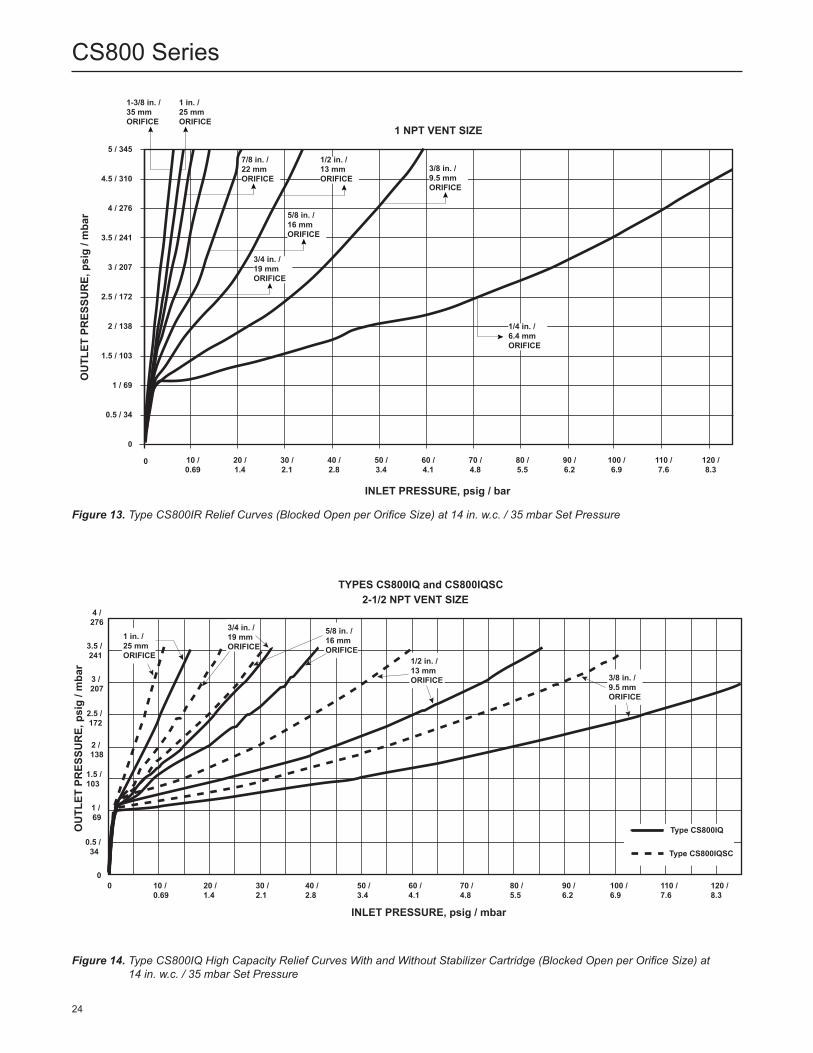
Figure 13. Type CS800IR Relief Curves (Blocked Open per Orifice Size) at 14 in. w.c. / 35 mbar Set Pressure
Figure 14. Type CS800IQ High Capacity Relief Curves With and Without Stabilizer Cartridge (Blocked Open per Orifice Size) at 14 in. w.c. / 35 mbar Set Pressure
INLET PRESSURE, psig / bar
OU
TLET
PR
ESSU
RE,
psi
g / m
bar
1 NPT VENT SIZE5 / 345
4.5 / 310
3.5 / 241
2.5 / 172
1.5 / 103
0.5 / 34
4 / 276
3 / 207
2 / 138
1 / 69
0
0 10 / 0.69
20 / 1.4
30 / 2.1
40 / 2.8
50 / 3.4
60 / 4.1
70 / 4.8
80 / 5.5
90 / 6.2
100 / 6.9
110 / 7.6
120 / 8.3
1-3/8 in. /35 mmORIFICE
1 in. /25 mmORIFICE
1/2 in. /13 mmORIFICE
3/8 in. /9.5 mmORIFICE
1/4 in. /6.4 mmORIFICE
5/8 in. /16 mmORIFICE
3/4 in. /19 mmORIFICE
7/8 in. /22 mmORIFICE
2-1/2 NPT VENT SIZETYPES CS800IQ and CS800IQSC
OU
TLET
PR
ESSU
RE,
psi
g / m
bar
0
1 / 69
2 / 138
3 / 207
4 /276
0.5 / 34
1.5 / 103
2.5 / 172
3.5 / 241
0 10 / 0.69
20 / 1.4
30 / 2.1
40 / 2.8
50 / 3.4
60 / 4.1
70 / 4.8
80 / 5.5
90 / 6.2
100 / 6.9
110 / 7.6
120 / 8.3
INLET PRESSURE, psig / mbar
1 in. /25 mmORIFICE
3/4 in. /19 mmORIFICE
5/8 in. /16 mmORIFICE
1/2 in. /13 mmORIFICE 3/8 in. /
9.5 mmORIFICE
Type CS800IQ
Type CS800IQSC
24
CS800 Series

Table 23. Types CS800, CS803 and CS804 Series Internal Registration Flow Capacities for 14 in. w.c. / 35 mbar Setpoint for 2 in. / DN 50 Body Size
SETPOINTACCURACY SPRING
Droop Boost Set Range Part Number / Color14 in. w.c. -2 in. w.c. 2 in. w.c. 10 to 16 in. w.c.
GE30340X012 / White35 mbar -5 mbar 5 mbar 25 to 40 mbar
CAPACITIES IN SCFH / Nm3/h OF 0.6 SPECIFIC GRAVITY NATURAL GAS
Inlet PressureOrifice Size, In. / mm
1/4 / 6.4 3/8 / 9.5 1/2 / 13 5/8 / 16 3/4 / 19 7/8 / 22 1 / 25 1-3/8 / 35(1)
SCFH Nm3/h SCFH Nm3/h SCFH Nm3/h SCFH Nm3/h SCFH Nm3/h SCFH Nm3/h SCFH Nm3/h SCFH Nm3/hpsig bar Body Size: 2 in. / DN 50
1 0.07 450 12.1 630 16.9 770 20.7 1300 34.9 1500 40.3 1600 43.0 1700 45.6 2700 72.5
2 0.14 600 16.1 1000 26.8 1800 48.3 2240 60.1 2800 75.2 3260 87.5 3800 102 3800 102
3 0.21 750 20.1 1210 32.5 2200 59.1 2700 72.5 3200 85.9 3700 99.3 4300 115 6060 163
5 0.34 1050 28.2 1750 47.0 2800 75.2 3300 88.6 4000 107 4600 124 5300 142 10,200 274
10 0.69 1400 37.6 2720 73.0 4250 114 6500 175 9200 247 10,300 277 11,650 313 14,550 391
15 1.0 1750 47.0 3700 99.3 5700 153 9600 258 14,400 387 16,100 432 17,910 481 17,110 459
20 1.4 2170 58.3 4700 126 7950 213 11,700 314 16,200 435 18,800 505 20,290 545
25 1.7 2560 68.7 5700 153 10,200 274 12,400 333 18,000 483 21,400 575 22,000 591
30 2.1 2910 78.1 6440 173 10,310 277 12,400 333 18,220 489 21,400 575
40 2.8 3540 95.0 7770 209 10,540 283 13,020 350 18,680 502 21,400 575
50 3.4 4170 112 9190 247 10,770 289 14,500 389 19,140 514 21,400(2) 575(2)
60 4.1 4800 129 10,900 293 11,000 295 14,900(2) 400(2) 19,600(2) 526(2)
80 5.5 6100 164 12,550 337 12,550 337
100 6.9 7400 199 14,100 379 14,100 379
125 8.6 9100 244 16,120 433
Blank areas indicate where maximum operating inlet pressure for a given orifice size is exceeded.1. Not available on the Type CS803.2. When stabilizer cartridge used with Types CS800, CS803 or CS804 could exhibit a 20% reduction in capacity for conditions marked.
Table 24. Types CS800, CS803 and CS804 Internal Registration Flow Capacities for 1 psig / 0.07 bar Setpoint for 1-1/4 in. / DN 32 Body Size at 1% ABS Accuracy
SETPOINTACCURACY: + / - 1% ABS SPRING
Droop Boost Set Range Part Number / Color1 psig -4.3 in. w.c. 4.3 in. w.c. 14 to 30 in. w.c. GE30341X012 /
Dark Green0.07 bar -11 mbar 11 mbar 35 to 75 mbar
CAPACITIES IN SCFH / Nm3/h OF 0.6 SPECIFIC GRAVITY NATURAL GAS
Inlet Pressure
Orifice Size, In. / mm
1/4 / 6.4 3/8 / 9.5 1/2 / 13 5/8 / 16 3/4 / 19 7/8 / 22 1 / 25 1-3/8 / 35(1)(2)
SCFH Nm3/h SCFH Nm3/h SCFH Nm3/h SCFH Nm3/h SCFH Nm3/h SCFH Nm3/h SCFH Nm3/h SCFH Nm3/h
psig bar Body Size: 1-1/4 in. / DN 32
2 0.14 732 19.7 1144 30.7 1709 45.9 2572 69.0 2799 75.1 3023 81.2 3151 84.6 3683 98.9
3 0.21 959 25.8 1458 39.1 2420 65.0 3091 83.0 3284 88.2 3713 99.7 3965 106 4418 119
5 0.34 1264 33.9 2229 59.8 3268 87.7 3877 104 4321 116 4663 125 4875 131 5348 144
10 0.69 1612 43.3 3197 85.8 4459 120 5282 142 5401 145 5706 153 5968 160 6210 167
15 1.0 1953 52.4 4030 108 5276 142 5851 157 6160 165 6283 169 6456 173 6679 179
20 1.4 2280 61.2 4698 126 5757 155 6400 172 6520 175 6324 170 6810 183
25 1.7 2608 70.0 5251 141 6078 163 6637 178 6834 183 6847 184 7019 188
30 2.1 2944 79.0 5625 151 6418 172 6672 179 6969 187 7000 188 7098 191
40 2.8 3615 97.1 6443 173 6929 186 7196 193 7196 193 7145 192
50 3.4 4262 114 6859 184 7168 192 7247 195 7330 197 7534 202
60 4.1 4949 133 10,218 274 7382 198 7338 197 7475 201 7593 204
80 5.5 6246 168 7306 196 7468 200 7254 195 5614 151
100 6.9 7039 189 7501 201 7382 198
125 8.6 5473 147 5638 151
Blank areas indicate where maximum operating inlet pressure for a given orifice size is exceeded.1. Not available on the Type CS803.2. Type CS824 exhibits a 20% reduction in capacity for indicated orifice size. Multiply listed values by a factor of 0.8.
25
CS800 Series

Table 25. Types CS800, CS803 and CS804 Internal Registration Flow Capacities for 1 psig / 0.07 bar Setpoint for 1-1/2 in. / DN 40 Body Size at 1% ABS Accuracy
SETPOINTACCURACY: + / - 1% ABS SPRING
Droop Boost Set Range Part Number / Color1 psig -4.3 in. w.c. 4.3 in. w.c. 14 to 30 in. w.c. GE30341X012 /
Dark Green0.07 bar -11 mbar 11 mbar 35 to 75 mbar
CAPACITIES IN SCFH / Nm3/h OF 0.6 SPECIFIC GRAVITY NATURAL GAS
Inlet Pressure
Orifice Size, In. / mm
1/4 / 6.4 3/8 / 9.5 1/2 / 13 5/8 / 16 3/4 / 19 7/8 / 22 1 / 25 1-3/8 / 35(1)(2)
SCFH Nm3/h SCFH Nm3/h SCFH Nm3/h SCFH Nm3/h SCFH Nm3/h SCFH Nm3/h SCFH Nm3/h SCFH Nm3/h
psig bar Body Size: 1-1/2 in. / DN 40
2 0.14 650 17.4 1050 28.2 1350 36.2 1800 48.3 2450 65.8 2600 69.8 2700 72.5 3000 80.5
3 0.21 780 20.9 1400 37.6 1800 48.3 2260 60.7 2900 77.9 3130 84.0 3360 90.2 3730 100
5 0.34 1050 28.2 2100 56.4 2700 72.5 3200 85.9 3800 102 4200 113 4700 126 5200 140
10 0.69 1500 40.3 2800 75.2 3700 99.3 4600 124 5600 150 6300 169 7000 188 7300 196
15 1.0 1950 52.3 3750 101 4900 132 5800 156 6900 185 7600 204 8500 228 8750 235
20 1.4 2200 59.1 4600 124 5800 156 6900 185 8150 219 9200 247 10,350 278
25 1.7 2500 67.1 5000 134 7250 195 8100 217 9050 243 9500 255 10,850 291
30 2.1 2800 75.2 6000 161 8200 220 8700 234 9400 252 9500 255 11,000 295
40 2.8 3550 95.3 7350 197 9100 244 9300 250 9500 255 9500 255
50 3.4 4050 109 8450 227 10,300 276 10,300 277 10,300 277 10,300 277
60 4.1 4800 129 9050 243 10,450 281 10,500 282 10,550 283 10,550 283
80 5.5 5900 158 11,000 295 11,000 295 11,000 295 11,000 295
100 6.9 7400 199 11,150 299 11,150 299
125 8.6 9000 242 11,750 315
Blank areas indicate where maximum operating inlet pressure for a given orifice size is exceeded.1. Not available on the Type CS803.2. Type CS824 exhibits a 20% reduction in capacity for indicated orifice size. Multiply listed values by a factor of 0.8.
Table 26. Types CS800, CS803 and CS804 Internal Registration Flow Capacities for 1 psig / 0.07 bar Setpoint for 2 in. / DN 50 Body Size at 1% ABS Accuracy
SETPOINTACCURACY: + / - 1% ABS SPRING
Droop Boost Set Range Part Number / Color1 psig -4.3 in. w.c. 4.3 in. w.c. 14 to 30 in. w.c. GE30341X012 /
Dark Green0.07 bar -11 mbar 11 mbar 35 to 75 mbar
CAPACITIES IN SCFH / Nm3/h OF 0.6 SPECIFIC GRAVITY NATURAL GAS
Inlet Pressure
Orifice Size, In. / mm
1/4 / 6.4 3/8 / 9.5 1/2 / 13 5/8 / 16 3/4 / 19 7/8 / 22 1 / 25 1-3/8 / 35(1)
SCFH Nm3/h SCFH Nm3/h SCFH Nm3/h SCFH Nm3/h SCFH Nm3/h SCFH Nm3/h SCFH Nm3/h SCFH Nm3/h
psig bar Body Size: 2 in. / DN 50
2 0.14 570 15.3 970 26.0 1910 51.2 1910 51.2 2750 73.7 2900 77.7 3100 831 3300 88.4
3 0.21 730 19.6 1460 39.1 2250 60.3 2660 71.3 3200 85.8 3630 97.3 4150 111 5200 139
5 0.34 1050 28.1 2200 59.0 2750 73.7 3400 91.1 4100 110 5100 137 6250 168 9000 241
10 0.69 1500 40.2 2500 67.0 4050 109 6100 163 8500 228 10,700 287 13,250 355 13,700 367
15 1.0 1900 50.9 3450 92.5 5800 155 9000 241 13,000 348 14,400 386 16,000 429 16,300 437
20 1.4 2240 60.0 4800 129 7700 206 10,200 273 13,300 356 15,700 421 18,500 496
25 1.7 2500 67.0 5600 150 10,400 279 13,100 351 16,500 442 17,700 474 19,000 509
30 2.1 2900 77.7 6350 170 11,950 320 15,000 402 18,800 504 19,000 509 19,300 517
40 2.8 3650 97.8 7850 210 14,550 390 16,700 448 19,300 517 19,500 523
50 3.4 4250 114 9300 249 16,700 448 18,400 493 20,500 549 20,700 555
60 4.1 4900 131 10,950 293 19,400 520 20,000 536 20,800 557 21,000 563
80 5.5 6200 166 13,790 370 20,400 547 20,600 552 20,800 557
100 6.9 7400 198 16,510 443 21,100 565
125 8.6 9350 251 20,200 541
Blank areas indicate where maximum operating inlet pressure for a given orifice size is exceeded.1. Not available on the Type CS803.
26
CS800 Series

Table 27. Types CS800, CS803 and CS804 Internal Registration Flow Capacities for 1 psig / 0.07 bar Setpoint for 1-1/4 in. / DN 32 Body Size at 2% ABS Accuracy
Table 28. Types CS800, CS803 and CS804 Internal Registration Flow Capacities for 1 psig / 0.07 bar Setpoint for 1-1/2 in. / DN 40 Body Size at 2% ABS Accuracy
SETPOINTACCURACY: + / - 2% ABS SPRING
Droop Boost Set Range Part Number / Color1 psig -8.7 in. w.c. 8.7 in. w.c. 14 to 30 in. w.c. GE30341X012 /
Dark Green0.07 bar -22 mbar 22 mbar 35 to 75 mbar
SETPOINTACCURACY: + / - 2% ABS SPRING
Droop Boost Set Range Part Number / Color1 psig -8.7 in. w.c. 8.7 in. w.c. 14 to 30 in. w.c. GE30341X012 /
Dark Green0.07 bar -22 mbar 22 mbar 35 to 75 mbar
CAPACITIES IN SCFH / Nm3/h OF 0.6 SPECIFIC GRAVITY NATURAL GAS
Inlet Pressure
Orifice Size, In. / mm
1/4 / 6.4 3/8 / 9.5 1/2 / 13 5/8 / 16 3/4 / 19 7/8 / 22 1 / 25 1-3/8 / 35(1)(2)
SCFH Nm3/h SCFH Nm3/h SCFH Nm3/h SCFH Nm3/h SCFH Nm3/h SCFH Nm3/h SCFH Nm3/h SCFH Nm3/h
psig bar Body Size: 1-1/4 in. / DN 32
2 0.14 776 20.8 1364 36.6 2418 64.9 3270 87.8 4147 111 4552 122 4927 132 5820 156
3 0.21 990 26.6 1719 46.1 3225 86.6 4153 111 4823 129 5484 147 5853 157 6545 176
5 0.34 1271 34.1 2403 64.5 4265 115 5509 148 6082 163 6670 179 6842 184 7409 199
10 0.69 1615 43.3 3552 95.4 6087 163 7290 196 7536 202 7988 214 8030 216 8457 227
15 1.0 1955 52.5 4339 116 7293 196 8204 220 8251 222 8559 230 8685 233 8825 237
20 1.4 2284 61.3 5040 135 7966 214 8767 235 8735 234 8759 235 8966 241
25 1.7 2609 70.0 5811 156 8450 227 9093 244 9083 244 9137 245 9143 245
30 2.1 2955 79.3 6543 176 8847 237 9347 251 9338 251 9252 248 9307 250
40 2.8 3616 97.1 8034 216 9349 251 9725 261 9506 255 9388 252
50 3.4 4286 115 9295 250 9633 259 9852 264 9633 259 9695 260
60 4.1 4966 133 13,055 350 9781 263 9903 266 9714 261 9706 261
80 5.5 6294 169 10,010 269 9904 266 9977 268 7679 206
100 6.9 7620 205 10,044 270 9915 266
125 8.6 8666 233 8053 216
Blank areas indicate where maximum operating inlet pressure for a given orifice size is exceeded.1. Not available on the Type CS803.2. Type CS824 exhibits a 20% reduction in capacity for indicated orifice size. Multiply listed values by a factor of 0.8.
CAPACITIES IN SCFH / Nm3/h OF 0.6 SPECIFIC GRAVITY NATURAL GAS
Inlet Pressure
Orifice Size, In. / mm
1/4 / 6.4 3/8 / 9.5 1/2 / 13 5/8 / 16 3/4 / 19 7/8 / 22 1 / 25 1-3/8 / 35(1)(2)
SCFH Nm3/h SCFH Nm3/h SCFH Nm3/h SCFH Nm3/h SCFH Nm3/h SCFH Nm3/h SCFH Nm3/h SCFH Nm3/h
psig bar Body Size: 1-1/2 in. / DN 40
2 0.14 740 19.9 1450 38.9 2100 56.4 2800 75.2 3700 99.3 4100 110 4650 125 5350 144
3 0.21 910 24.4 1800 48.3 2580 69.3 3400 91.3 4480 120 5100 137 5730 154 6200 166
5 0.34 1180 31.7 2320 62.3 3550 95.3 4700 126 6050 162 6900 185 7900 212 7900 212
10 0.69 1630 43.8 3380 90.7 5100 137 6700 180 8550 230 9000 242 9550 256 10,100 271
15 1.0 1960 52.6 4170 112 6700 180 7900 212 9400 252 10,300 277 11,250 302 11,400 306
20 1.4 2250 60.4 4740 127 8100 217 9200 247 10,500 282 11,300 303 12,200 328
25 1.7 2660 71.4 5710 153 10,100 271 10,800 290 11,550 310 12,000 322 12,600 338
30 2.1 2960 79.5 6440 173 10,550 283 11,400 306 12,350 332 12,700 341 13,100 352
40 2.8 3650 98.0 7850 211 10,550 283 11,400 306 12,350 332 12,350 332
50 3.4 4350 117 9250 248 12,000 322 12,500 336 13,000 349 13,000 349
60 4.1 5000 134 10,900 293 12,600 338 12,800 344 13,000 349 13,000 349
80 5.5 6340 170 12,550 337 13,000 349 13,000 349 13,000 349
100 6.9 7740 208 12,900 346 13,450 361
125 8.6 9380 252 13,450 361
Blank areas indicate where maximum operating inlet pressure for a given orifice size is exceeded.1. Not available on the Type CS803.2. Type CS824 exhibits a 20% reduction in capacity for indicated orifice size. Multiply listed values by a factor of 0.8.
27
CS800 Series

Table 29. Types CS800, CS803 and CS804 Internal Registration Flow Capacities for 1 psig / 0.07 bar Setpoint for 2 in. / DN 50 Body Size at 2% ABS Accuracy
SETPOINTACCURACY: + / - 2% ABS SPRING
Droop Boost Set Range Part Number / Color1 psig -8.7 in. w.c. 8.7 in. w.c. 14 to 30 in. w.c. GE30341X012 /
Dark Green0.07 bar -22 mbar 22 mbar 35 to 75 mbar
CAPACITIES IN SCFH / Nm3/h OF 0.6 SPECIFIC GRAVITY NATURAL GAS
Inlet Pressure
Orifice Size, In. / mm
1/4 / 6.4 3/8 / 9.5 1/2 / 13 5/8 / 16 3/4 / 19 7/8 / 22 1 / 25 1-3/8 / 35(1)
SCFH Nm3/h SCFH Nm3/h SCFH Nm3/h SCFH Nm3/h SCFH Nm3/h SCFH Nm3/h SCFH Nm3/h SCFH Nm3/h
psig bar Body Size: 2 in. / DN 50
2 0.14 700 18.8 1110 29.8 2340 62.8 3100 83.2 4100 110 4800 129 5470 147 7900 212
3 0.21 850 22.8 1710 45.9 2960 79.5 4060 109 5180 139 6430 173 7630 205 10,030 269
5 0.34 1150 30.9 2250 60.4 4000 107 5800 156 7920 213 9700 260 11,620 312 14,300 384
10 0.69 1610 43.2 3510 94.2 6200 166 8900 239 12,250 329 14,750 396 18,280 491 19,480 523
15 1.0 1910 51.3 4250 114 7850 211 11,500 309 15,010 403 18,700 502 21,390 574 22,760 611
20 1.4 2240 60.1 4980 134 9100 244 13,600 365 18,990 510 22,300 599 24,110 647
25 1.7 2610 70.1 5770 155 10,300 277 15,500 416 21,800 585 26,200 703 26,620 715
30 2.1 2910 78.1 6540 176 11,800 317 18,300 491 24,710 663 27,670 743 27,670 743
40 2.8 3630 97.4 8000 215 14,300 384 21,600 580 29,870 802 30,500 819
50 3.4 4330 116 9300 250 16,700 448 24,400 655 31,950 858 31,950 858
60 4.1 4950 133 10,850 291 19,500 524 26,100 701 32,010 859 32,410 870
80 5.5 6310 169 13,600 365 24,600 660 28,900 776 32,010 859
100 6.9 7640 205 16,810 451 30,200 811
125 8.6 9370 252 20,480 550
Blank areas indicate where maximum operating inlet pressure for a given orifice size is exceeded.1. Not available on the Type CS803.
Table 30. Types CS800, CS803 and CS804 Internal Registration Flow Capacities for 1 psig / 0.07 bar Setpoint for 1-1/4 in. / DN 32 Body Size at 10% Accuracy
SETPOINTACCURACY: + / - 10% GAUGE SPRING
Droop Boost Set Range Part Number / Color1 psig -2.8 in. w.c. 2.8 in. w.c. 14 to 30 in. w.c. GE30341X012 /
Dark Green0.07 bar -7 mbar 7 mbar 35 to 75 mbar
CAPACITIES IN SCFH / Nm3/h OF 0.6 SPECIFIC GRAVITY NATURAL GAS
Inlet Pressure
Orifice Size, In. / mm
1/4 / 6.4 3/8 / 9.5 1/2 / 13 5/8 / 16 3/4 / 19 7/8 / 22 1 / 25 1-3/8 / 35(1)(2)
SCFH Nm3/h SCFH Nm3/h SCFH Nm3/h SCFH Nm3/h SCFH Nm3/h SCFH Nm3/h SCFH Nm3/h SCFH Nm3/h
psig bar Body Size: 1-1/4 in. / DN 32
2 0.14 696 18.7 913 24.5 1379 37.0 1724 46.3 2187 58.7 2309 62.0 2335 62.7 2799 75.1
3 0.21 933 25.0 1169 31.4 2010 54.0 2431 65.2 2421 65.0 2698 72.4 2995 80.4 3442 92.4
5 0.34 1225 32.9 1739 46.7 2474 66.4 2863 76.9 3080 82.7 3498 93.9 3712 100 4305 116
10 0.69 1592 42.7 2370 63.6 3305 88.7 4051 109 4119 111 4502 121 4697 126 5024 135
15 1.0 1931 51.8 3183 85.4 4024 108 4614 124 4946 133 5068 136 5242 141 5377 144
20 1.4 2266 60.8 3697 99.2 4603 124 5163 139 5130 138 5058 136 5497 148
25 1.7 2567 68.9 4119 111 4763 128 5312 143 5462 147 5635 151 5699 153
30 2.1 2913 78.2 4458 120 4917 132 5457 146 5567 149 5736 154 5738 154
40 2.8 3605 96.8 5303 142 5422 146 5514 148 5795 156 5844 157
50 3.4 4198 113 5415 145 5699 153 5773 155 5954 160 6149 165
60 4.1 4886 131 9196 247 5773 155 5799 156 5918 159 6212 167
80 5.5 5756 155 5954 160 5858 157 5918 159 4687 126
100 6.9 5658 152 5918 159 5933 159
125 8.6 3339 89.6 4221 113
Blank areas indicate where maximum operating inlet pressure for a given orifice size is exceeded.1. Not available on the Type CS803.2. Type CS824 exhibits a 20% reduction in capacity for indicated orifice size. Multiply listed values by a factor of 0.8.
28
CS800 Series

Table 31. Types CS800, CS803 and CS804 Internal Registration Flow Capacities for 1 psig / 0.07 bar Setpoint for 1-1/2 in. / DN 40 Body Size at 10% Accuracy
SETPOINTACCURACY: + / - 10% GAUGE SPRING
Droop Boost Set Range Part Number / Color1 psig -2.8 in. w.c. 2.8 in. w.c. 14 to 30 in. w.c. GE30341X012 /
Dark Green0.07 bar -7 mbar 7 mbar 35 to 75 mbar
CAPACITIES IN SCFH / Nm3/h OF 0.6 SPECIFIC GRAVITY NATURAL GAS
Inlet Pressure
Orifice Size, In. / mm
1/4 / 6.4 3/8 / 9.5 1/2 / 13 5/8 / 16 3/4 / 19 7/8 / 22 1 / 25 1-3/8 / 35(1)(2)
SCFH Nm3/h SCFH Nm3/h SCFH Nm3/h SCFH Nm3/h SCFH Nm3/h SCFH Nm3/h SCFH Nm3/h SCFH Nm3/h
psig bar Body Size: 1-1/2 in. / DN 40
2 0.14 530 14.2 710 19.1 940 25.2 1220 32.8 1430 38.4 1430 38.4 1330 35.7 1930 51.8
3 0.21 620 16.6 1070 28.7 1150 30.9 1490 40.0 1770 47.5 1700 45.6 1700 45.6 2530 67.9
5 0.34 810 21.7 1560 41.9 1650 44.3 2050 55.0 2530 67.9 2450 65.8 2450 65.8 3750 101
10 0.69 1360 36.5 2080 55.8 3100 83.2 3840 103 4680 126 4840 130 4950 133 5330 143
15 1.0 1650 44.3 2920 78.4 3860 104 4670 125 5570 150 6290 169 7000 188 7500 201
20 1.4 1960 52.6 3650 98.0 4560 122 5040 135 5570 150 6680 179 8120 218
25 1.7 2400 64.4 4400 118 5550 149 6700 180 7900 212 7900 212 8650 232
30 2.1 2570 69.0 5270 142 5650 152 7080 190 8220 221 9300 250 9990 268
40 2.8 3360 90.2 3960 106 7300 196 7790 209 8470 227 8510 229
50 3.4 3960 106 7920 213 7970 214 8590 231 8920 240 8920 240
60 4.1 4660 125 7820 210 8020 215 8520 229 9020 242 9020 242
80 5.5 5860 157 8740 235 9020 242 9020 242 9020 242
100 6.9 7350 197 8960 241 10,150 273
125 8.6 9050 243 10,020 269
Blank areas indicate where maximum operating inlet pressure for a given orifice size is exceeded.1. Not available on the Type CS803.2. Type CS824 exhibits a 20% reduction in capacity for indicated orifice size. Multiply listed values by a factor of 0.8.
Table 32. Types CS800, CS803 and CS804 Internal Registration Flow Capacities for 1 psig / 0.07 bar Setpoint for 2 in. / DN 50 Body Size at 10% Accuracy
SETPOINTACCURACY: + / - 10% GAUGE SPRING
Droop Boost Set Range Part Number / Color1 psig -2.8 in. w.c. 2.8 in. w.c. 14 to 30 in. w.c. GE30341X012 /
Dark Green0.07 bar -7 mbar 7 mbar 35 to 75 mbar
CAPACITIES IN SCFH / Nm3/h OF 0.6 SPECIFIC GRAVITY NATURAL GAS
Inlet Pressure
Orifice Size, In. / mm
1/4 / 6.4 3/8 / 9.5 1/2 / 13 5/8 / 16 3/4 / 19 7/8 / 22 1 / 25 1-3/8 / 35(1)
SCFH Nm3/h SCFH Nm3/h SCFH Nm3/h SCFH Nm3/h SCFH Nm3/h SCFH Nm3/h SCFH Nm3/h SCFH Nm3/h
psig bar Body Size: 2 in. / DN 50
2 0.14 500 13.4 860 23.1 1420 38.1 1450 38.9 1450 38.9 1450 38.9 1450 38.9 1450 38.9
3 0.21 610 16.4 1030 27.7 1420 38.1 1660 44.6 2000 53.7 2300 61.7 2700 72.5 3260 87.5
5 0.34 850 22.8 1640 44.0 1800 48.3 2130 57.2 2570 69.0 3320 89.1 4190 113 5140 138
10 0.69 1350 36.2 1750 47.0 2380 63.9 4000 107 5920 159 6540 176 7110 191 8470 227
15 1.0 1610 43.2 2690 72.2 3540 95.0 5290 142 7470 201 7680 206 8050 216 9580 257
20 1.4 2000 53.7 3760 101 5350 144 7430 200 9760 262 9760 262 9800 263
25 1.7 2400 64.4 4340 117 7000 188 9770 262 13,100 352 13,410 360 13,890 373
30 2.1 2470 66.3 5120 137 7500 201 11,420 307 16,250 436 17,320 465 18,520 497
40 2.8 3490 93.7 7300 196 13,100 352 15,510 416 18,410 494 20,910 561
50 3.4 3900 105 8020 215 16,110 433 17,090 459 18,410 494 22,290 598
60 4.1 4600 124 10,700 287 18,800 505 19,700 529 20,700 556 22,410 602
80 5.5 5700 153 13,000 349 18,800 505 19,700 529 20,700 556
100 6.9 7190 193 15,720 422 19,070 512
125 8.6 9190 247 19,600 526
Blank areas indicate where maximum operating inlet pressure for a given orifice size is exceeded.1. Not available on the Type CS803.
29
CS800 Series

Table 33. Types CS800, CS803(1) and CS804(2) Internal Registration Flow Capacities for 1 psig / 0.07 bar Setpoint for 1-1/4 in. / DN 32 Body Size at 20% Accuracy
Table 34. Types CS800, CS803(1) and CS804(2) Internal Registration Flow Capacities for 1 psig / 0.07 bar Setpoint for 1-1/2 in. / DN 40 Body Size at 20% Accuracy
SETPOINTACCURACY: + / - 20% GAUGE SPRING
Droop Boost Set Range Part Number / Color1 psig -5.5 in. w.c. 5.5 in. w.c. 14 to 30 in. w.c. GE30341X012 /
Dark Green0.07 bar -14 mbar 14 mbar 35 to 75 mbar
SETPOINTACCURACY: + / - 20% GAUGE SPRING
Droop Boost Set Range Part Number / Color1 psig -5.5 in. w.c. 5.5 in. w.c. 14 to 30 in. w.c. GE30341X012 /
Dark Green0.07 bar -14 mbar 14 mbar 35 to 75 mbar
CAPACITIES IN SCFH / Nm3/h OF 0.6 SPECIFIC GRAVITY NATURAL GAS
Inlet Pressure
Orifice Size, In. / mm
1/4 / 6.4 3/8 / 9.5 1/2 / 13 5/8 / 16 3/4 / 19 7/8 / 22 1 / 25 1-3/8 / 35(1)(2)
SCFH Nm3/h SCFH Nm3/h SCFH Nm3/h SCFH Nm3/h SCFH Nm3/h SCFH Nm3/h SCFH Nm3/h SCFH Nm3/h
psig bar Body Size: 1-1/4 in. / DN 32
2 0.14 747 20.0 1218 32.7 1993 53.5 2780 74.6 3219 86.4 3502 94.0 3770 101 4297 115
3 0.21 970 26.0 1566 42.0 2836 76.1 3545 95.2 3881 104 4265 115 4435 119 4999 134
5 0.34 1271 34.1 2296 61.6 3643 97.8 4474 120 4808 129 5319 143 5539 149 6040 162
10 0.69 1612 43.3 3434 92.2 5147 138 5985 161 6115 164 6448 173 6604 177 7016 188
15 1.0 1955 52.5 4231 114 6036 162 6685 179 6869 184 7030 189 7212 194 7417 199
20 1.4 2284 61.3 4999 134 6562 176 7268 195 7251 195 7153 192 7509 202
25 1.7 2609 70.0 5714 153 6814 183 7281 195 7555 203 7590 204 7749 208
30 2.1 2949 79.2 6308 169 7212 194 7311 196 7434 200 7775 209 7833 210
40 2.8 3596 96.5 7217 194 7772 209 7804 209 8040 216 7949 213
50 3.4 4281 115 7645 205 8104 218 8307 223 8219 221 8185 220
60 4.1 4963 133 11,423 307 8204 220 8406 226 8253 222 8362 224
80 5.5 6289 169 8198 220 8174 219 8315 223 6285 169
100 6.9 7599 204 8264 222 8285 222
125 8.6 6641 178 6397 172
Blank areas indicate where maximum operating inlet pressure for a given orifice size is exceeded.1. Not available on the Type CS803.2. Type CS824 exhibits a 20% reduction in capacity for indicated orifice size. Multiply listed values by a factor of 0.8.
CAPACITIES IN SCFH / Nm3/h OF 0.6 SPECIFIC GRAVITY NATURAL GAS
Inlet Pressure
Orifice Size, In. / mm
1/4 / 6.4 3/8 / 9.5 1/2 / 13 5/8 / 16 3/4 / 19 7/8 / 22 1 / 25 1-3/8 / 35(1)(2)
SCFH Nm3/h SCFH Nm3/h SCFH Nm3/h SCFH Nm3/h SCFH Nm3/h SCFH Nm3/h SCFH Nm3/h SCFH Nm3/h
psig bar Body Size: 1-1/2 in. / DN 40
2 0.14 500 13.4 750 20.1 1750 47.0 2000 53.7 2250 60.4 2300 61.7 2400 64.4 2850 76.5
3 0.21 700 18.8 1100 29.5 1930 51.8 2200 59.1 2630 70.6 2900 77.9 3210 86.2 3680 98.8
5 0.34 1100 29.5 1800 48.3 2300 61.7 2800 75.2 3400 91.3 4100 110 4850 130 5350 144
10 0.69 1600 43.0 3200 85.9 4600 124 5800 156 7250 195 8000 215 8800 236 8800 236
15 1.0 1900 51.0 3970 107 5400 145 6600 177 8030 216 8700 234 9410 253 10,020 269
20 1.4 2200 59.1 4750 128 6200 166 7400 199 8820 237 9400 252 10,020 269
25 1.7 2500 67.1 5520 148 7000 188 8200 220 9610 258 10,100 271 10,630 285
30 2.1 2800 75.2 6300 169 7800 209 9000 242 10,400 279 10,800 290 11,250 302
40 2.8 3500 94.0 7400 199 8410 226 9400 252 10,600 285 10,600 285
50 3.4 4200 113 8500 228 9030 242 9800 263 10,800 290 10,800 290
60 4.1 4900 132 9600 258 9650 259 10,300 277 11,000 295 11,000 295
80 5.5 6100 164 10,070 270 10,800 290 10,900 293 11,000 295
100 6.9 7300 196 10,550 283 11,950 321
125 8.6 9100 244 10,550 283
Blank areas indicate where maximum operating inlet pressure for a given orifice size is exceeded.1. Not available on the Type CS803.2. Type CS824 exhibits a 20% reduction in capacity for indicated orifice size. Multiply listed values by a factor of 0.8.
30
CS800 Series

Table 35. Types CS800, CS803 and CS804 Internal Registration Flow Capacities for 1 psig / 0.07 bar Setpoint for 2 in. / DN 50 Body Size at 20% Accuracy
SETPOINTACCURACY: + / - 20% GAUGE SPRING
Droop Boost Set Range Part Number / Color1 psig -5.5 in. w.c. 5.5 in. w.c. 14 to 30 in. w.c. GE30341X012 /
Dark Green0.07 bar -14 mbar 14 mbar 35 to 75 mbar
CAPACITIES IN SCFH / Nm3/h OF 0.6 SPECIFIC GRAVITY NATURAL GAS
Inlet Pressure
Orifice Size, In. / mm
1/4 / 6.4 3/8 / 9.5 1/2 / 13 5/8 / 16 3/4 / 19 7/8 / 22 1 / 25 1-3/8 / 35(1)
SCFH Nm3/h SCFH Nm3/h SCFH Nm3/h SCFH Nm3/h SCFH Nm3/h SCFH Nm3/h SCFH Nm3/h SCFH Nm3/h
psig bar Body Size: 2 in. / DN 50
2 0.14 650 17.4 1040 27.9 2200 59.1 2570 69.0 3200 85.9 3400 91.3 3600 96.6 4500 121
3 0.21 800 21.5 1560 41.9 2530 67.9 3100 83.2 3730 100 4300 115 4960 133 6330 170
5 0.34 1100 29.5 2300 61.7 3200 85.9 3900 105 4800 129 6100 164 7700 207 10,000 269
10 0.69 1600 43.0 3000 80.5 4300 115 7500 201 11,400 306 13,200 354 15,200 408 16,300 438
15 1.0 1900 51.0 4000 107 6900 185 10,800 290 14,560 391 18,000 483 19,930 535 20,170 542
20 1.4 2300 61.7 4900 132 9100 244 13,600 365 18,520 497 21,300 572 22,680 609
25 1.7 2600 69.8 5600 150 10,500 282 15,500 416 21,700 583 24,300 652 24,410 655
30 2.1 2900 77.9 6500 175 11,800 317 17,900 481 24,020 645 25,320 680 25,580 687
40 2.8 3700 99.3 8000 215 14,500 389 20,100 540 27,000 725 27,810 747
50 3.4 4300 115 9300 250 16,600 446 21,700 583 27,810 747 27,810 747
60 4.1 4900 132 10,940 294 19,500 524 24,900 669 29,050 780 29,050 780
80 5.5 6300 169 13,830 371 24,000 644 27,400 736 29,070 780
100 6.9 7700 207 16,680 448 29,500 792
125 8.6 9600 258 20,200 542
Blank areas indicate where maximum operating inlet pressure for a given orifice size is exceeded.1. Not available on the Type CS803.
Table 36. Types CS820, CS823 and CS824 Internal Registration Flow Capacities for 2 psig / 0.14 bar Setpoint for 1-1/4 in. / DN 32 Body Size at 1% ABS Accuracy
SETPOINTACCURACY: + / - 1% ABS SPRING
Droop Boost Set Range Part Number / Color2 psig -0.17 psig 0.17 psig 1 to 2.5 psig
GE30342X012 / Dark Blue0.14 bar -12 mbar 12 mbar 0.07 to 0.17 bar
CAPACITIES IN SCFH / Nm3/h OF 0.6 SPECIFIC GRAVITY NATURAL GAS
Inlet Pressure
Orifice Size, In. / mm
1/4 / 6.4 3/8 / 9.5 1/2 / 13 5/8 / 16 3/4 / 19 7/8 / 22 1 / 25 1-3/8 / 35(1)
SCFH Nm3/h SCFH Nm3/h SCFH Nm3/h SCFH Nm3/h SCFH Nm3/h SCFH Nm3/h SCFH Nm3/h SCFH Nm3/h
psig bar Body Size: 1-1/4 in. / DN 32
3 0.21 614 16.5 665 17.9 824 22.1 1674 44.9 1715 46.0 1781 47.8 2056 55.2 2487 66.8
5 0.34 863 23.2 1072 28.8 1634 43.9 1933 51.9 2305 61.9 2522 67.7 3077 82.6 3807 102
10 0.69 1328 35.7 1581 42.4 2489 66.8 3093 83.0 3845 103 4124 111 4466 120 5259 141
15 1.0 1594 42.8 2366 63.5 3196 85.8 3931 106 4780 128 5025 135 5497 148 5696 153
20 1.4 1950 52.3 2882 77.4 3989 107 4770 128 5608 151 5683 153 5855 157
25 1.7 2210 59.3 3473 93.2 4376 117 5256 141 5893 158 6108 164 6358 171
30 2.1 2631 70.6 3862 104 4854 130 5350 144 6251 168 6450 173 6453 173
40 2.8 3340 89.7 4809 129 5429 146 6039 162 6524 175 6770 182
50 3.4 4097 110 5265 141 6393 172 6664 179 6949 187 7017 188
60 4.1 4712 126 5445 146 6091 163 6930 186 7554 203 7517 202
80 5.5 5909 159 6154 165 6871 184 7498 201 7596 204
100 6.9 6750 181 6331 170 6994 188
125 8.6 7030 189 6319 170
Blank areas indicate where maximum operating inlet pressure for a given orifice size is exceeded.1. Not available on the Type CS823.
31
CS800 Series

Figure 15. Type CS800IR Relief Curves (Blocked Open per Orifice Size) at 1 psig / 0.07 bar Set Pressure
Figure 16. Type CS800IQ High Capacity Relief Curves (Blocked Open per Orifice Size) at 1 psig / 0.07 bar Set Pressure
INLET PRESSURE, psig / bar
1 NPT VENT SIZE
OU
TLET
PR
ESSU
RE,
psi
g / m
bar
0
0
10 / 0.69
6 / 414
5 / 345
4 / 276
3 / 207
2 / 138
1 / 69
20 / 1.4
30 / 2.1
40 / 2.8
50 / 3.4
60 / 4.1
70 / 4.8
80 / 5.5
90 / 6.2
100 / 6.9
110 / 7.6
120 / 8.3
1-3/8 in. /35 mmORIFICE
1 in. /25 mmORIFICE
7/8 in. /22 mmORIFICE
5/8 in. /16 mmORIFICE
3/8 in. /9.5 mmORIFICE
1/2 in. /13 mmORIFICE
3/4 in. /19 mmORIFICE
1/4 in. /6.4 mmORIFICE
INLET PRESSURE, psig / bar
HIGH CAPACITY 2-1/2 NPT VENT SIZE
OU
TLET
PR
ESSU
RE,
psi
g / m
bar
0
0
10 / 0.69
6 / 414
5 / 345
4 / 276
3 / 207
2 / 138
1 / 69
20 / 1.4
30 / 2.1
40 / 2.8
50 / 3.4
60 / 4.1
70 / 4.8
80 / 5.5
90 / 6.2
100 / 6.9
110 / 7.6
120 / 8.3
1-3/8 in. /35 mmORIFICE
1 in. /25 mmORIFICE
7/8 in. /22 mmORIFICE
3/4 in. /19 mmORIFICE
5/8 in. /16 mmORIFICE
1/2 in. /13 mmORIFICE
3/8 in. /9.5 mmORIFICE
1/4 in. / 6.4 mmORIFICE
32
CS800 Series

Table 37. Types CS820, CS823 and CS824 Internal Registration Flow Capacities for 2 psig / 0.14 bar Setpoint for 1-1/2 in. / DN 40 Body Size at 1% ABS Accuracy
SETPOINTACCURACY: + / - 1% ABS SPRING
Droop Boost Set Range Part Number / Color2 psig -0.17 psig 0.17 psig 1 to 2.5 psig
GE30342X012 / Dark Blue0.14 bar -12 mbar 12 mbar 0.07 to 0.17 bar
CAPACITIES IN SCFH / Nm3/h OF 0.6 SPECIFIC GRAVITY NATURAL GAS
Inlet Pressure
Orifice Size, In. / mm
1/4 / 6.4 3/8 / 9.5 1/2 / 13 5/8 / 16 3/4 / 19 7/8 / 22 1 / 25 1-3/8 / 35(1)
SCFH Nm3/h SCFH Nm3/h SCFH Nm3/h SCFH Nm3/h SCFH Nm3/h SCFH Nm3/h SCFH Nm3/h SCFH Nm3/h
psig bar Body Size: 1-1/2 in. / DN 40
3 0.21 710 19.1 1000 26.8 1000 26.8 1380 37.0 1600 43.0 1780 47.8 1800 48.3 2510 67.4
5 0.34 900 24.2 1160 31.1 1740 46.7 2080 55.8 2440 65.5 2920 78.4 3300 88.6 4150 111
10 0.69 1410 37.9 1980 53.2 2930 78.7 3780 102 4280 115 4760 128 5250 141 6430 173
15 1.0 1920 51.5 2690 72.2 4040 109 5060 136 5580 150 5760 155 6920 186 7720 207
20 1.4 2310 62.0 3370 90.5 5180 139 6350 171 6870 184 7500 201 7870 211
25 1.7 2570 69.0 4050 109 6050 162 7280 195 7580 204 7890 212 8440 227
30 2.1 2930 78.7 4720 127 6960 187 7800 209 8570 230 8230 221 9050 243
40 2.8 3510 94.2 6280 169 8370 225 9400 252 9450 254 9290 250
50 3.4 4330 116 7550 203 9320 250 9440 253 10,220 274 10,040 270
60 4.1 4940 133 8960 241 10,010 269 10,420 280 10,420 280 10,140 272
80 5.5 6360 171 10,320 277 10,890 292 11,180 300 11,180 300
100 6.9 7560 203 11,090 298 11,290 303
125 8.6 9300 250 11,290 303
Blank areas indicate where maximum operating inlet pressure for a given orifice size is exceeded.1. Not available on the Type CS823.
3 0.21 650 17.4 810 21.7 1080 29.0 1610 43.2 1690 45.4 1860 49.9 2690 72.2 3060 82.1
5 0.34 1040 27.9 1290 34.6 1850 49.7 2540 68.2 2900 77.9 3960 106 4270 115 5340 143
10 0.69 1480 39.7 2240 60.1 3410 91.5 4850 130 5780 155 7560 203 9230 248 10,800 290
15 1.0 1870 50.2 3260 87.5 5410 145 7700 207 8490 228 11,750 315 12,530 336 14,550 391
20 1.4 2280 61.2 4070 109 7360 198 10,180 273 11,900 320 13,250 356 14,760 396
25 1.7 2600 69.8 4980 134 9100 244 12,640 339 15,050 404 16,190 435 17,120 460
30 2.1 2920 78.4 5780 155 10,640 286 14,500 389 16,950 455 17,370 466 18,170 488
40 2.8 3510 94.2 7640 205 14,010 376 17,930 481 20,100 537 20,230 542
50 3.4 4240 113 8790 236 16,930 455 21,160 568 22,560 606 20,230 542
60 4.1 4980 134 10,650 286 19,640 527 23,460 630 23,600 634 20,230 542
80 5.5 6300 169 13,600 365 24,830 667 24,830 667 24,830 667
100 6.9 7620 205 16,280 437 28,790 773
125 8.6 9370 252 19,900 534
1. Type CS823 exhibits a 15% reduction in capacity for indicated orifice size. Multiply listed values by a factor of 0.85.2. Not available on the Type CS823.3. Type CS824 exhibits a 20% reduction in capacity for indicated orifice size. Multiply listed values by a factor of 0.8 .
CAPACITIES IN SCFH / Nm3/h OF 0.6 SPECIFIC GRAVITY NATURAL GAS
Inlet Pressure
Orifice Size, In. / mm
1/4 / 6.4 3/8 / 9.5(1) 1/2 / 13 5/8 / 16 3/4 / 19 7/8 / 22 1 / 25(1) 1-3/8 / 35(2)(3)
SCFH Nm3/h SCFH Nm3/h SCFH Nm3/h SCFH Nm3/h SCFH Nm3/h SCFH Nm3/h SCFH Nm3/h SCFH Nm3/h
psig bar Body Size: 2 in. / DN 50
Table 38. Types CS820, CS823(1)(2) and CS824(3) Internal Registration Flow Capacities for 2 psig / 0.14 bar Setpoint for 2 in. / DN 50 Body Size at 1% ABS Accuracy
SETPOINTACCURACY: + / - 1% ABS SPRING
Droop Boost Set Range Part Number / Color2 psig -0.17 psig 0.17 psig 1 to 2.5 psig
GE30342X012 / Dark Blue0.14 bar -12 mbar 12 mbar 0.07 to 0.17 bar
33
CS800 Series
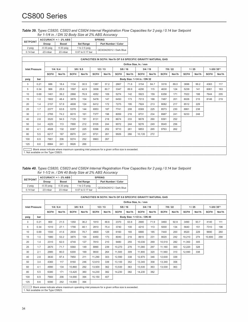
Table 39. Types CS820, CS823 and CS824 Internal Registration Flow Capacities for 2 psig / 0.14 bar Setpoint for 1-1/4 in. / DN 32 Body Size at 2% ABS Accuracy
Table 40. Types CS820, CS823 and CS824 Internal Registration Flow Capacities for 2 psig / 0.14 bar Setpoint for 1-1/2 in. / DN 40 Body Size at 2% ABS Accuracy
SETPOINTACCURACY: + / - 2% ABS SPRING
Droop Boost Set Range Part Number / Color2 psig -0.33 psig 0.33 psig 1 to 2.5 psig
GE30342X012 / Dark Blue0.14 bar -23 mbar 23 mbar 0.07 to 0.17 bar
SETPOINTACCURACY: + / - 2% ABS SPRING
Droop Boost Set Range Part Number / Color2 psig -0.33 psig 0.33 psig 1 to 2.5 psig
GE30342X012 / Dark Blue0.14 bar -23 mbar 23 mbar 0.07 to 0.17 bar
CAPACITIES IN SCFH / Nm3/h OF 0.6 SPECIFIC GRAVITY NATURAL GAS
Inlet Pressure
Orifice Size, In. / mm
1/4 / 6.4 3/8 / 9.5 1/2 / 13 5/8 / 16 3/4 / 19 7/8 / 22 1 / 25 1-3/8 / 35(1)
SCFH Nm3/h SCFH Nm3/h SCFH Nm3/h SCFH Nm3/h SCFH Nm3/h SCFH Nm3/h SCFH Nm3/h SCFH Nm3/h
psig bar Body Size: 1-1/4 in. / DN 32
3 0.21 686 18.4 1134 30.5 1387 37.2 2667 71.6 3154 84.7 3316 89.0 3696 99.2 4363 117
5 0.34 966 25.9 1597 42.9 3008 80.7 3347 89.9 4290 115 4630 124 5239 141 6061 163
10 0.69 1461 39.2 2866 76.9 4052 109 5274 142 5923 159 6358 171 7022 188 7644 205
15 1.0 1802 48.4 3876 104 5478 147 6450 173 7013 188 7487 201 8026 215 8146 219
20 1.4 2157 57.9 4608 124 6412 172 7275 195 7924 213 8082 217 8512 229
25 1.7 2377 63.8 5378 144 6953 187 7741 208 8369 225 8573 230 8861 238
30 2.1 2765 74.2 6015 161 7377 198 8059 216 8731 234 8987 241 9233 248
40 2.8 3520 94.5 7125 191 8131 218 8674 233 9678 260 9391 252
50 3.4 4225 113 7890 212 9105 244 9072 244 9276 249 9540 256
60 4.1 4928 132 8387 225 9396 252 9710 261 9853 265 9763 262
80 5.5 6217 167 8970 241 9731 261 9926 266 10,135 272
100 6.9 7661 206 9374 252 9963 267
125 8.6 8984 241 9926 266
Blank areas indicate where maximum operating inlet pressure for a given orifice size is exceeded.1. Not available on the Type CS823.
CAPACITIES IN SCFH / Nm3/h OF 0.6 SPECIFIC GRAVITY NATURAL GAS
Inlet Pressure
Orifice Size, In. / mm
1/4 / 6.4 3/8 / 9.5 1/2 / 13 5/8 / 16 3/4 / 19 7/8 / 22 1 / 25 1-3/8 / 35(1)
SCFH Nm3/h SCFH Nm3/h SCFH Nm3/h SCFH Nm3/h SCFH Nm3/h SCFH Nm3/h SCFH Nm3/h SCFH Nm3/h
psig bar Body Size: 1-1/2 in. / DN 40
3 0.21 800 21.5 1350 36.2 1810 48.6 2370 63.6 2680 71.9 3460 92.9 3490 93.7 4140 111
5 0.34 1010 27.1 1790 48.1 2810 75.4 3740 100 4210 113 5000 134 5640 151 7310 196
10 0.69 1550 41.6 2930 78.7 4800 129 6160 165 6880 185 7440 200 8520 229 9690 260
15 1.0 1980 53.2 3870 104 6450 173 8040 216 8610 231 9020 242 10,210 274 10,800 290
20 1.4 2310 62.0 4740 127 7810 210 9480 255 10,030 269 10,510 282 11,350 305
25 1.7 2670 71.7 5560 149 8890 239 10,270 276 11,080 297 11,160 300 12,220 328
30 2.1 2980 80.0 6300 169 9830 264 11,500 309 11,900 320 11,560 310 12,590 338
40 2.8 3630 97.4 7850 211 11,290 303 12,590 338 12,870 346 12,630 339
50 3.4 4360 117 9160 246 12,610 339 13,100 352 13,340 358 13,340 358
60 4.1 4990 134 10,860 292 13,500 362 13,530 363 13,530 363 13,530 363
80 5.5 6380 171 13,420 360 14,230 382 14,230 382 14,230 382
100 6.9 7660 206 14,690 394 15,150 407
125 8.6 9390 252 14,690 394
Blank areas indicate where maximum operating inlet pressure for a given orifice size is exceeded.1. Not available on the Type CS823.
34
CS800 Series

3 0.21 720 19.3 1150 30.9 1980 53.2 2470 66.3 3230(2) 86.7(2) 3540 95.0 4200 113 5640 151
5 0.34 1140 30.6 1850 49.7 3140 84.3 4120 111 5150(2) 138(2) 6120 164 7050 189 9210 247
10 0.69 1600 43.0 3100 83.2 5380 144 7250 195 8730 234 11,300 303 12,550 337 16,570 445
15 1.0 1980 53.2 4150 111 7440 200 10,230 275 12,410 333 15,290 411 16,900 454 19,470 523
20 1.4 2330 62.6 4930 132 9100 244 12,570 337 15,870 426 18,530 497 19,190 515
25 1.7 2650 71.1 5670 152 10,450 281 14,690 394 18,720 503 21,120 567 22,120 594
30 2.1 2940 78.9 6170 166 11,770 316 16,960 455 20,850 560 23,130 621 23,740 637
40 2.8 3580 96.1 7920 213 14,780 397 20,790 558 24,670 662 26,630 715
50 3.4 4280 115 9090 244 17,550 471 24,300 652 26,400 709 28,150 756
60 4.1 4980 134 10,860 292 20,470 550 28,340 761 28,340 761 29,780 800
80 5.5 6310 169 13,700 368 25,840 694 30,680 824 30,680 824
100 6.9 7650 205 16,580 445 30,980 832
125 8.6 9360 251 20,190 542
1. Type CS823 exhibits a 10% reduction in capacity for indicated orifice size. Multiply listed values by a factor of 0.9. 2. Due to droop, the Type CS823 exhibits a 15% reduction in capacity for indicated conditions. Multiply listed values by a factor of 0.85.3. Not available on the Type CS823.4. Type CS824 exhibits a 20% reduction in capacity for indicated orifice size. Multiply listed values by a factor of 0.8 .
CAPACITIES IN SCFH / Nm3/h OF 0.6 SPECIFIC GRAVITY NATURAL GAS
Inlet Pressure
Orifice Size, In. / mm
1/4 / 6.4 3/8 / 9.5 1/2 / 13 5/8 / 16 3/4 / 19 7/8 / 22 1 / 25(1) 1-3/8 / 35(3)(4)
SCFH Nm3/h SCFH Nm3/h SCFH Nm3/h SCFH Nm3/h SCFH Nm3/h SCFH Nm3/h SCFH Nm3/h SCFH Nm3/h
psig bar Body Size: 2 in. / DN 50
Table 41. Types CS820, CS823(1)(2) and CS824(4) Internal Registration Flow Capacities for 2 psig / 0.14 bar Setpoint for 2 in. / DN 50 Body Size at 2% ABS Accuracy
SETPOINTACCURACY: + / - 2% ABS SPRING
Droop Boost Set Range Part Number / Color2 psig -0.33 psig 0.33 psig 1 to 2.5 psig
GE30342X012 / Dark Blue0.14 bar -23 mbar 23 mbar 0.07 to 0.17 bar
Table 42. Types CS820, CS823 and CS824 Internal Registration Flow Capacities for 2 psig / 0.14 bar Setpoint for 1-1/4 in. / DN 32 Body Size at 10% Accuracy
SETPOINTACCURACY: + / - 10% GAUGE SPRING
Droop Boost Set Range Part Number / Color2 psig -0.20 psig 0.20 psig 1 to 2.5 psig
GE30342X012 / Dark Blue0.14 bar -14 mbar 14 mbar 0.07 to 0.17 bar
CAPACITIES IN SCFH / Nm3/h OF 0.6 SPECIFIC GRAVITY NATURAL GAS
Inlet Pressure
Orifice Size, In. / mm
1/4 / 6.4 3/8 / 9.5 1/2 / 13 5/8 / 16 3/4 / 19 7/8 / 22 1 / 25 1-3/8 / 35(1)
SCFH Nm3/h SCFH Nm3/h SCFH Nm3/h SCFH Nm3/h SCFH Nm3/h SCFH Nm3/h SCFH Nm3/h SCFH Nm3/h
psig bar Body Size: 1-1/4 in. / DN 32
3 0.21 634 17.0 762 20.5 968 26.0 1835 49.3 2153 57.8 2228 59.8 2351 63.1 2899 77.8
5 0.34 896 24.1 1191 32.0 2065 55.4 2243 60.2 2723 73.1 2941 79.0 3462 92.9 4163 112
10 0.69 1382 37.1 1980 53.1 2837 76.1 3569 95.8 4236 114 4626 124.2 4976 133.6 5724 154
15 1.0 1702 45.7 2880 77.3 3574 95.9 4507 121 5173 139 5814 156.1 6015 161.5 6373 171
20 1.4 2045 54.9 3382 90.8 4417 119 5382 144 6188 166 6372 171.1 6455 173.3
25 1.7 2255 60.5 4032 108 5096 137 6009 161 6408 172 6661 178.8 6870 184.4
30 2.1 2669 71.7 4463 120 5334 143 6208 167 6773 182 6991 187.7 7237 194.3
40 2.8 3398 91.2 5416 145 6209 167 6828 183 7344 197 7586 203.6
50 3.4 4141 111 5866 157 7027 189 7121 191 7627 205 7725 207
60 4.1 4806 129 6301 169 7061 190 8053 216 8085 217 8080 217
80 5.5 5998 161 6996 188 7434 200 7991 215 8219 221
100 6.9 7362 198 7109 191 7781 209
125 8.6 7629 205 7343 197
Blank areas indicate where maximum operating inlet pressure for a given orifice size is exceeded.1. Not available on the Type CS823.
35
CS800 Series
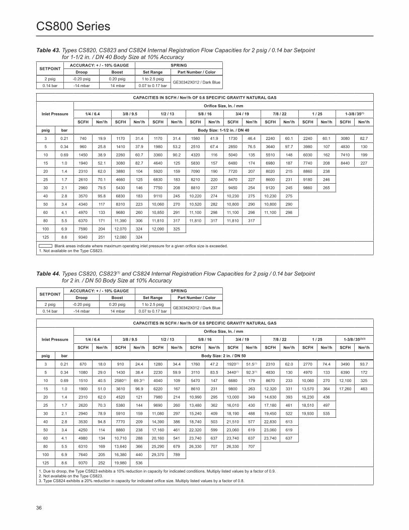
Table 43. Types CS820, CS823 and CS824 Internal Registration Flow Capacities for 2 psig / 0.14 bar Setpoint for 1-1/2 in. / DN 40 Body Size at 10% Accuracy
SETPOINTACCURACY: + / - 10% GAUGE SPRING
Droop Boost Set Range Part Number / Color2 psig -0.20 psig 0.20 psig 1 to 2.5 psig
GE30342X012 / Dark Blue0.14 bar -14 mbar 14 mbar 0.07 to 0.17 bar
CAPACITIES IN SCFH / Nm3/h OF 0.6 SPECIFIC GRAVITY NATURAL GAS
Inlet Pressure
Orifice Size, In. / mm
1/4 / 6.4 3/8 / 9.5 1/2 / 13 5/8 / 16 3/4 / 19 7/8 / 22 1 / 25 1-3/8 / 35(1)
SCFH Nm3/h SCFH Nm3/h SCFH Nm3/h SCFH Nm3/h SCFH Nm3/h SCFH Nm3/h SCFH Nm3/h SCFH Nm3/h
psig bar Body Size: 1-1/2 in. / DN 40
3 0.21 740 19.9 1170 31.4 1170 31.4 1560 41.9 1730 46.4 2240 60.1 2240 60.1 3080 82.7
5 0.34 960 25.8 1410 37.9 1980 53.2 2510 67.4 2850 76.5 3640 97.7 3980 107 4830 130
10 0.69 1450 38.9 2260 60.7 3360 90.2 4320 116 5040 135 5510 148 6030 162 7410 199
15 1.0 1940 52.1 3080 82.7 4640 125 5830 157 6480 174 6980 187 7740 208 8440 227
20 1.4 2310 62.0 3880 104 5920 159 7090 190 7720 207 8020 215 8860 238
25 1.7 2610 70.1 4660 125 6830 183 8210 220 8470 227 8600 231 9180 246
30 2.1 2960 79.5 5430 146 7750 208 8810 237 9450 254 9120 245 9860 265
40 2.8 3570 95.8 6830 183 9110 245 10,220 274 10,230 275 10,230 275
50 3.4 4340 117 8310 223 10,060 270 10,520 282 10,800 290 10,800 290
60 4.1 4970 133 9680 260 10,850 291 11,100 298 11,100 298 11,100 298
80 5.5 6370 171 11,390 306 11,810 317 11,810 317 11,810 317
100 6.9 7590 204 12,070 324 12,090 325
125 8.6 9340 251 12,080 324
Blank areas indicate where maximum operating inlet pressure for a given orifice size is exceeded.1. Not available on the Type CS823.
Table 44. Types CS820, CS823(1) and CS824 Internal Registration Flow Capacities for 2 psig / 0.14 bar Setpoint for 2 in. / DN 50 Body Size at 10% Accuracy
SETPOINTACCURACY: + / - 10% GAUGE SPRING
Droop Boost Set Range Part Number / Color2 psig -0.20 psig 0.20 psig 1 to 2.5 psig
GE30342X012 / Dark Blue0.14 bar -14 mbar 14 mbar 0.07 to 0.17 bar
3 0.21 670 18.0 910 24.4 1280 34.4 1760 47.2 1920(1) 51.5(1) 2310 62.0 2770 74.4 3490 93.7
5 0.34 1080 29.0 1430 38.4 2230 59.9 3110 83.5 3440(1) 92.3(1) 4830 130 4970 133 6390 172
10 0.69 1510 40.5 2580(1) 69.3(1) 4040 109 5470 147 6680 179 8670 233 10,060 270 12,100 325
15 1.0 1900 51.0 3610 96.9 6220 167 8610 231 9800 263 12,320 331 13,570 364 17,260 463
20 1.4 2310 62.0 4520 121 7980 214 10,990 295 13,000 349 14,630 393 16,230 436
25 1.7 2620 70.3 5380 144 9690 260 13,480 362 16,010 430 17,180 461 18,510 497
30 2.1 2940 78.9 5910 159 11,080 297 15,240 409 18,190 488 19,450 522 19,930 535
40 2.8 3530 94.8 7770 209 14,390 386 18,740 503 21,510 577 22,830 613
50 3.4 4250 114 8860 238 17,160 461 22,320 599 23,060 619 23,060 619
60 4.1 4980 134 10,710 288 20,160 541 23,740 637 23,740 637 23,740 637
80 5.5 6310 169 13,640 366 25,290 679 26,330 707 26,330 707
100 6.9 7640 205 16,380 440 29,370 789
125 8.6 9370 252 19,980 536
1. Due to droop, the Type CS823 exhibits a 10% reduction in capacity for indicated conditions. Multiply listed values by a factor of 0.9.2. Not available on the Type CS823.3. Type CS824 exhibits a 20% reduction in capacity for indicated orifice size. Multiply listed values by a factor of 0.8.
CAPACITIES IN SCFH / Nm3/h OF 0.6 SPECIFIC GRAVITY NATURAL GAS
Inlet Pressure
Orifice Size, In. / mm
1/4 / 6.4 3/8 / 9.5 1/2 / 13 5/8 / 16 3/4 / 19 7/8 / 22 1 / 25 1-3/8 / 35(2)(3)
SCFH Nm3/h SCFH Nm3/h SCFH Nm3/h SCFH Nm3/h SCFH Nm3/h SCFH Nm3/h SCFH Nm3/h SCFH Nm3/h
psig bar Body Size: 2 in. / DN 50
36
CS800 Series

Table 45. Types CS820, CS823 and CS824 Internal Registration Flow Capacities for 2 psig / 0.14 bar Setpoint for 1-1/4 in. / DN 32 Body Size at 20% Accuracy
SETPOINTACCURACY: + / - 20% GAUGE SPRING
Droop Boost Set Range Part Number / Color2 psig -0.40 psig 0.40 psig 1 to 2.5 psig
GE30342X012 / Dark Blue0.14 bar -28 mbar 28 mbar 0.07 to 0.17 bar
CAPACITIES IN SCFH / Nm3/h OF 0.6 SPECIFIC GRAVITY NATURAL GAS
Inlet Pressure
Orifice Size, In. / mm
1/4 / 6.4 3/8 / 9.5 1/2 / 13 5/8 / 16 3/4 / 19 7/8 / 22 1 / 25 1-3/8 / 35(1)
SCFH Nm3/h SCFH Nm3/h SCFH Nm3/h SCFH Nm3/h SCFH Nm3/h SCFH Nm3/h SCFH Nm3/h SCFH Nm3/h
psig bar Body Size: 1-14 in. / DN 32
3 0.21 707 19.0 1255 33.7 1486 39.9 2877 77.2 3555 95.4 3852 103 4326 116 5163 139
5 0.34 986 26.5 1803 48.4 3291 88.3 3771 101 4796 129 5305 142 5688 153 6540 176
10 0.69 1480 39.7 3123 83.8 4696 126 5816 156 6674 179 7021 188 7627 205 7983 214
15 1.0 1826 49.0 4122 111 5934 159 7215 194 7761 208 8143 219 8744 235 9128 245
20 1.4 2169 58.2 4850 130 7043 189 7925 213 8614 231 8879 238 9452 254
25 1.7 2410 64.7 5656 152 7771 209 8608 231 9050 243 9406 252 9738 261
30 2.1 2796 75.1 6287 169 8330 224 9005 242 9455 254 9729 261 9737 261
40 2.8 3535 94.9 7692 206 8971 241 9679 260 9895 266 10,087 271
50 3.4 4240 114 8567 230 9844 264 10,021 269 10,328 277 10,234 275
60 4.1 4940 133 9243 248 10,124 271.8 10,479 281 10,590 284 10,481 281
80 5.5 6249 168 9728 261 10,582 284.1 10,523 282 10,773 289
100 6.9 7658 206 10,282 276 10,994 295.1
125 8.6 9145 245 10,630 285
Blank areas indicate where maximum operating inlet pressure for a given orifice size is exceeded.1. Not available on the Type CS823.
Table 46. Types CS820, CS823 and CS824 Internal Registration Flow Capacities for 2 psig / 0.14 bar Setpoint for 1-1/2 in. / DN 40 Body Size at 20% Accuracy
SETPOINTACCURACY: + / - 20% GAUGE SPRING
Droop Boost Set Range Part Number / Color2 psig -0.40 psig 0.40 psig 1 to 2.5 psig
GE30342X012 / Dark Blue0.14 bar -28 mbar 28 mbar 0.07 to 0.17 bar
CAPACITIES IN SCFH / Nm3/h OF 0.6 SPECIFIC GRAVITY NATURAL GAS
Inlet Pressure
Orifice Size, In. / mm
1/4 / 6.4 3/8 / 9.5 1/2 / 13 5/8 / 16 3/4 / 19 7/8 / 22 1 / 25 1-3/8 / 35(1)
SCFH Nm3/h SCFH Nm3/h SCFH Nm3/h SCFH Nm3/h SCFH Nm3/h SCFH Nm3/h SCFH Nm3/h SCFH Nm3/h
psig bar Body Size: 1-1/2 in. / DN 40
3 0.21 820 22.0 1420 38.1 1960 52.6 2830 76.0 3200 85.9 3950 106 4160 112 4620 124
5 0.34 1060 28.5 1860 49.9 3220 86.4 4200 113 5020 135 5920 159 6570 176 8000 215
10 0.69 1590 42.7 3120 83.8 5230 140 6870 184 7600 204 8410 226 9580 257 11,220 301
15 1.0 1990 53.4 4090 110 6970 187 8880 238 9820 264 10,200 274 11,520 309 11,790 317
20 1.4 2310 62.0 4880 131 8440 227 10,380 279 11,160 300 11,490 309 12,630 339
25 1.7 2680 71.9 5640 151 9630 259 11,480 308 12,480 335 12,130 326 13,570 364
30 2.1 2980 80.0 6340 170 10,670 286 12,360 332 12,960 348 12,990 349 13,920 374
40 2.8 3660 98.3 7850 211 12,140 326 14,150 380 14,240 382 13,470 362
50 3.4 4360 117 9260 249 13,460 361 14,190 381 14,920 401 14,280 383
60 4.1 5000 134 10,860 292 14,740 396 14,910 400 15,260 410 14,620 393
80 5.5 6400 172 13,710 368 15,440 415 15,440 415 15,440 415
100 6.9 7670 206 15,900 427 16,200 435
125 8.6 9410 253 16,080 432
Blank areas indicate where maximum operating inlet pressure for a given orifice size is exceeded.1. Not available on the Type CS823.
37
CS800 Series

Table 47. Types CS820, CS823(1)(2) and CS824 Internal Registration Flow Capacities for 2 psig / 0.14 bar Setpoint for 2 in. / DN 50 Body Size at 20% Accuracy
SETPOINTACCURACY: + / - 20% GAUGE SPRING
Droop Boost Set Range Part Number / Color2 psig -0.40 psig 0.40 psig 1 to 2.5 psig
GE30342X012 / Dark Blue0.14 bar -28 mbar 28 mbar 0.07 to 0.17 bar
3 0.21 730 19.6 1280 34.4 2140 57.4 2890 77.6 3400(2) 91.3(2) 4190 113 4800 129 6490 174
5 0.34 1150 30.9 1960 52.6 3440 92.3 4380 118 5700(2) 153(2) 6770 182 7960 214 11,840 318
10 0.69 1610 43.2 3260 87.5 5790 155 7870 211 9930 267 11,840 318 13,680 367 18,160 488
15 1.0 1980 53.2 4200 113 7760 208 10,520 282 13,510 363 16,080 432 18,220 489 20,810 559
20 1.4 2330 62.6 4950 133 9250 248 12,990 349 16,570 445 19,760 531 20,610 553
25 1.7 2660 71.4 5710 153 10,560 284 15,060 404 19,630 527 22,340 600 23,530 632
30 2.1 2940 78.9 6300 169 11,890 319 17,290 464 21,870 587 24,500 658 25,180 676
40 2.8 3600 96.6 7950 213 14,880 400 21,370 574 24,710 663 28,610 768
50 3.4 4280 115 9200 247 17,600 473 24,860 667 27,290 733 29,870 802
60 4.1 4980 134 10,890 292 20,430 549 29,670 797 29,670 797 30,930 830
80 5.5 6310 169 13,710 368 25,880 695 32,240 866 32,240 866
100 6.9 7650 205 16,620 446 31,200 838
125 8.6 9360 251 20,220 543
1. Type CS823 exhibits a 10% reduction in capacity for indicated orifice size. Multiply listed values by a factor of 0.9.2. Due to droop, the Type CS823 exhibits a 15% reduction in capacity for indicated conditions. Multiply listed values by a factor of 0.85.3. Not available on the Type CS823.4. Type CS824 exhibits a 20% reduction in capacity for indicated orifice size. Multiply listed values by a factor of 0.8.
CAPACITIES IN SCFH / Nm3/h OF 0.6 SPECIFIC GRAVITY NATURAL GAS
Inlet Pressure
Orifice Size, In. / mm
1/4 / 6.4 3/8 / 9.5 1/2 / 13 5/8 / 16 3/4 / 19 7/8 / 22 1 / 25(1) 1-3/8 / 35(3)(4)
SCFH Nm3/h SCFH Nm3/h SCFH Nm3/h SCFH Nm3/h SCFH Nm3/h SCFH Nm3/h SCFH Nm3/h SCFH Nm3/h
psig bar Body Size: 2 in. / DN 50
Table 48. Types CS820, CS823 and CS824 Internal Registration Flow Capacities for 5 psig / 0.34 bar Setpoint at 1% ABS Accuracy
SETPOINTACCURACY: + / - 1% ABS SPRING
Droop Boost Set Range Part Number / Color5 psig -0.20 psig 0.20 psig 2.5 to 5.5 psig
GE30343X012 / Yellow0.34 bar -14 mbar 14 mbar 0.17 to 0.38 bar
CAPACITIES IN SCFH / Nm3/h OF 0.6 SPECIFIC GRAVITY NATURAL GAS
Inlet Pressure
Orifice Size, In. / mm
1/4 / 6.4 3/8 / 9.5 1/2 / 13 5/8 / 16 3/4 / 19 7/8 / 22 1 / 25 1-3/8 / 35(1)
SCFH Nm3/h SCFH Nm3/h SCFH Nm3/h SCFH Nm3/h SCFH Nm3/h SCFH Nm3/h SCFH Nm3/h SCFH Nm3/h
psig bar Body Size: 1-1/4 in. / DN 32
10 0.69 797 21.4 615 16.5 1222 33 1538 41 1932 52 2003 54 2543 68 2767 74
15 1.0 769 20.6 1329 36 1670 45 2195 59 2425 65 2922 78 3407 91 3289 88
20 1.4 1098 29.5 1765 47 2200 59 2641 71 3072 82 3583 96 4000 107
25 1.7 1289 34.6 2139 57 2569 69 2909 78 3726 100 4191 113 4605 124
30 2.1 1417 38.0 2407 65 3024 81 3234 87 4232 114 4345 117 4764 128
40 2.8 1778 47.7 2961 79 3512 94 4316 116 5142 138 5124 138
50 3.4 2214 59 3491 94 4188 112 4383 118 5385 145 5571 150
60 4.1 2810 75 4312 116 4875 131 5286 142 5780 155 6108 164
80 5.5 3096 83 4906 132 5513 148 5097 137 6264 168
100 6.9 3585 96 5530 148 5887 158
125 8.6 3966 106 5988 161
Blank areas indicate where maximum operating inlet pressure for a given orifice size is exceeded.1. Not available on the Type CS823.
38
CS800 Series
- continued -

Figure 17. Type CS820IR Relief Curves (Blocked Open per Orifice Size) at 2 psig / 0.14 bar Set Pressure
Figure 18. Type CS820IQ High Capacity Relief Curves With and Without Stabilizer Cartridge (Blocked Open per Orifice Size) at 2 psig / 14 bar Set Pressure
INLET PRESSURE, psig / bar
1 NPT VENT SIZE
OU
TLET
PR
ESSU
RE,
psi
g / m
bar
0 10 / 0.69
7 / 483
6.5 / 448
6 / 414
5.5 / 379
5 / 345
4.5 / 310
4 / 276
3.5 / 241
3 / 207
2.5 / 172
2 / 13820 / 1.4
30 / 2.1
40 / 2.8
50 / 3.4
60 / 4.1
70 / 4.8
80 / 5.5
90 / 6.2
100 / 6.9
110 / 7.6
120 / 8.3
1-3/8 in. /35 mmORIFICE
7/8 in. /22 mmORIFICE
3/4 in. /19 mmORIFICE
5/8 in. /16 mmORIFICE
1 in. /25 mmORIFICE
1/2 in. /13 mmORIFICE
3/8 in. /9.5 mmORIFICE
1/4 in. /6.4 mmORIFICE
2-1/2 NPT VENT SIZETYPES CS820IQ and CS800IQSC
2 / 138
3 / 207
4 /276
4.5 /310
5 /345
5.5 /379
6 /414
2.5 / 172
3.5 / 241
0 10 / 0.69
20 / 1.4
30 / 2.1
40 / 2.8
50 / 3.4
60 / 4.1
70 / 4.8
80 / 5.5
90 / 6.2
100 / 6.9
110 / 7.6
120 / 8.3
INLET PRESSURE, psig / mbar
Type CS820IQ
Type CS820IQSC
1 in. /25 mmORIFICE
3/4 in. /19 mmORIFICE
5/8 in. /16 mmORIFICE
1/2 in. /13 mmORIFICE
3/8 in. /9.5 mmORIFICE
OU
TLET
PR
ESSU
RE,
psi
g / m
bar
39
CS800 Series

Table 48. Types CS820, CS823 and CS824 Internal Registration Flow Capacities for 5 psig / 0.34 bar Setpoint at 1% ABS Accuracy (continued)
SETPOINTACCURACY: + / - 1% ABS SPRING
Droop Boost Set Range Part Number / Color5 psig -0.20 psig 0.20 psig 2.5 to 5.5 psig
GE30343X012 / Yellow0.34 bar -14 mbar 14 mbar 0.17 to 0.38 bar
CAPACITIES IN SCFH / Nm3/h OF 0.6 SPECIFIC GRAVITY NATURAL GAS
Inlet Pressure
Orifice Size, In. / mm
1/4 / 6.4 3/8 / 9.5 1/2 / 13 5/8 / 16 3/4 / 19 7/8 / 22 1 / 25 1-3/8 / 35(1)(2)
SCFH Nm3/h SCFH Nm3/h SCFH Nm3/h SCFH Nm3/h SCFH Nm3/h SCFH Nm3/h SCFH Nm3/h SCFH Nm3/h
psig bar Body Size: 2 in. / DN 50
10 0.69 850 22.8 850 22.8 1270 34.1 1530 41.1 1900 51.0 2000 53.7 2390 64.2 3240 87.0
15 1.0 1150 30.9 1150 30.9 1920 51.5 2150 57.7 2790 74.9 2790 74.9 3750 101 5170 139
20 1.4 1490 40.0 1520 40.8 2390 64.2 2870 77.0 3360 90.2 3870 104 5030 135
25 1.7 1770 47.5 1770 47.5 2850 76.5 3350 89.9 4480 120 4480 120 6560 176
30 2.1 2020 54.2 2150 57.7 3470 93.2 4300 115 5060 136 5720 154 8010 215
40 2.8 2590 69.5 2900 77.9 4730 127 5780 155 7740 208 9120 245
50 3.4 3130 84.0 3630 97.4 6250 168 7200 193 9720 261 14,940 401
60 4.1 3460 92.9 4150 111 7950 213 8520 229 12,940 347 20,040 538
80 5.5 5070 136 5940 160 13,910 373 15,510 416 15,510 416
100 6.9 6800 183 8430 226 18,840 506
125 8.6 9090 244 15,390 413
Blank areas indicate where maximum operating inlet pressure for a given orifice size is exceeded.1. Not available on the Type CS823.2. Type CS824 exhibits a 20% reduction in capacity for indicated orifice size. Multiply listed values by a factor of 0.8.
SETPOINTACCURACY: + / - 1% ABS SPRING
Droop Boost Set Range Part Number / Color5 psig -0.20 psig 0.20 psig 2.5 to 5.5 psig
GE30343X012 / Yellow0.34 bar -14 mbar 14 mbar 0.17 to 0.38 bar
CAPACITIES IN SCFH / Nm3/h OF 0.6 SPECIFIC GRAVITY NATURAL GAS
Inlet Pressure
Orifice Size, In. / mm
1/4 / 6.4 3/8 / 9.5 1/2 / 13 5/8 / 16 3/4 / 19 7/8 / 22 1 / 25 1-3/8 / 35(1)
SCFH Nm3/h SCFH Nm3/h SCFH Nm3/h SCFH Nm3/h SCFH Nm3/h SCFH Nm3/h SCFH Nm3/h SCFH Nm3/h
psig bar Body Size: 1-1/2 in. / DN 40
10 0.69 930 25.0 940 25.2 1290 34.6 1760 47.2 1910 51.3 2320 62.3 2390 64.2 3300 88.6
15 1.0 1220 32.8 1220 32.8 1810 48.6 2370 63.6 2660 71.4 2860 76.8 3570 95.8 4320 116
20 1.4 1590 42.7 1590 42.7 2250 60.4 2950 79.2 3110 83.5 3880 104 4580 123
25 1.7 1900 51 1900 51.0 2730 73.3 3570 95.8 3890 104 4370 117 5790 155
30 2.1 2160 58 2200 59.1 3150 84.6 4140 111 4290 115 5380 144 6200 166
40 2.8 2690 72 2760 74.1 3750 101 4980 134 5110 137 6560 176
50 3.4 3250 87 3310 88.9 4650 125 6190 166 6500 175 8020 215
60 4.1 3850 103 4160 112 5690 153 7090 190 7410 199 8780 236
80 5.5 5130 138 5290 142 7500 201 8570 230 9230 248
100 6.9 6100 164 6100 164 9000 242
125 8.6 7320 197 7430 200
Blank areas indicate where maximum operating inlet pressure for a given orifice size is exceeded.1. Not available on the Type CS823.
40
CS800 Series

Table 49. Types CS820, CS823 and CS824 Internal Registration Flow Capacities for 5 psig / 0.34 bar Setpoint at 2% ABS Accuracy
SETPOINTACCURACY: + / - 2% ABS SPRING
Droop Boost Set Range Part Number / Color5 psig -0.39 psig 0.39 psig 2.5 to 5.5 psig
GE30343X012 / Yellow0.34 bar -27 mbar 27 mbar 0.17 to 0.38 bar
CAPACITIES IN SCFH / Nm3/h OF 0.6 SPECIFIC GRAVITY NATURAL GAS
Inlet Pressure
Orifice Size, In. / mm
1/4 / 6.4 3/8 / 9.5 1/2 / 13 5/8 / 16 3/4 / 19 7/8 / 22 1 / 25 1-3/8 / 35(1)
SCFH Nm3/h SCFH Nm3/h SCFH Nm3/h SCFH Nm3/h SCFH Nm3/h SCFH Nm3/h SCFH Nm3/h SCFH Nm3/h
psig bar Body Size: 1-1/4 in. / DN 32
10 0.69 1393 37.4 1152 30.9 2249 60 2760 74 3417 92 3773 101 4508 121 5165 139
15 1.0 1309 35.1 2384 64 3109 83 3918 105 4548 122 5347 144 5632 151 6436 173
20 1.4 1764 47.3 2987 80 3957 106 4702 126 5413 145 6245 168 6509 175
25 1.7 2188 58.7 3624 97 4513 121 5404 145 6461 173 6741 181 7226 194
30 2.1 2472 66.4 4093 110 5202 140 6077 163 7395 199 7230 194 7847 211
40 2.8 3221 86.5 5068 136 5964 160 7154 192 7927 213 8448 227
50 3.4 3843 103 5926 159 6652 179 7823 210 8668 233 8804 236
60 4.1 4533 122 5936 159 8041 216 8444 227 9011 242 9535 256
80 5.5 5197 140 8223 221 8902 239 9109 245 10,019 269
100 6.9 6137 165 8918 239 9384 252
125 8.6 7042 189 9572 257
Blank areas indicate where maximum operating inlet pressure for a given orifice size is exceeded.1. Not available on the Type CS823.
SETPOINTACCURACY: + / - 2% ABS SPRING
Droop Boost Set Range Part Number / Color5 psig -0.39 psig 0.39 psig 2.5 to 5.5 psig
GE30343X012 / Yellow0.34 bar -27 mbar 27 mbar 0.17 to 0.38 bar
CAPACITIES IN SCFH / Nm3/h OF 0.6 SPECIFIC GRAVITY NATURAL GAS
Inlet Pressure
Orifice Size, In. / mm
1/4 / 6.4 3/8 / 9.5 1/2 / 13 5/8 / 16 3/4 / 19 7/8 / 22 1 / 25 1-3/8 / 35(1)
SCFH Nm3/h SCFH Nm3/h SCFH Nm3/h SCFH Nm3/h SCFH Nm3/h SCFH Nm3/h SCFH Nm3/h SCFH Nm3/h
psig bar Body Size: 1-1/2 in. / DN 40
10 0.69 1360 36.5 1600 43.0 2170 58.3 2940 78.9 3480 93.4 3780 102 4560 122 5730 154
15 1.0 1890 50.7 2120 56.9 3140 84.3 4170 112 5030 135 5710 153 6760 182 7550 203
20 1.4 2210 59.3 2820 75.7 3960 106 5240 141 6010 161 7140 192 8240 221
25 1.7 2520 67.7 3250 87.2 4880 131 6150 165 7290 196 7670 206 9890 266
30 2.1 2660 71.4 3830 103 5290 142 7400 199 8040 216 8930 240 10,850 291
40 2.8 3370 90.5 5000 134 7010 188 8740 235 9440 253 11,050 297
50 3.4 3990 107 5870 158 8470 227 10,000 269 11,420 307 12,550 337
60 4.1 4910 132 7150 192 9430 253 11,230 302 12,620 339 13,220 355
80 5.5 6180 166 9260 249 11,910 320 13,760 369 14,570 391
100 6.9 7610 204 10,620 285 13,920 374
125 8.6 9160 246 11,740 315
Blank areas indicate where maximum operating inlet pressure for a given orifice size is exceeded.1. Not available on the Type CS823.
41
CS800 Series
- continued -
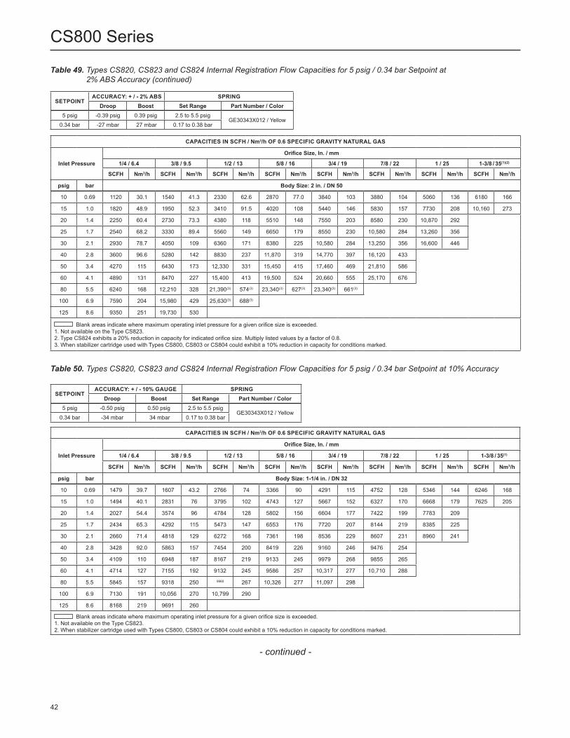
Table 50. Types CS820, CS823 and CS824 Internal Registration Flow Capacities for 5 psig / 0.34 bar Setpoint at 10% Accuracy
SETPOINTACCURACY: + / - 10% GAUGE SPRING
Droop Boost Set Range Part Number / Color5 psig -0.50 psig 0.50 psig 2.5 to 5.5 psig
GE30343X012 / Yellow0.34 bar -34 mbar 34 mbar 0.17 to 0.38 bar
CAPACITIES IN SCFH / Nm3/h OF 0.6 SPECIFIC GRAVITY NATURAL GAS
Inlet Pressure
Orifice Size, In. / mm
1/4 / 6.4 3/8 / 9.5 1/2 / 13 5/8 / 16 3/4 / 19 7/8 / 22 1 / 25 1-3/8 / 35(1)
SCFH Nm3/h SCFH Nm3/h SCFH Nm3/h SCFH Nm3/h SCFH Nm3/h SCFH Nm3/h SCFH Nm3/h SCFH Nm3/h
psig bar Body Size: 1-1/4 in. / DN 32
10 0.69 1479 39.7 1607 43.2 2766 74 3366 90 4291 115 4752 128 5346 144 6246 168
15 1.0 1494 40.1 2831 76 3795 102 4743 127 5667 152 6327 170 6668 179 7625 205
20 1.4 2027 54.4 3574 96 4784 128 5802 156 6604 177 7422 199 7783 209
25 1.7 2434 65.3 4292 115 5473 147 6553 176 7720 207 8144 219 8385 225
30 2.1 2660 71.4 4818 129 6272 168 7361 198 8536 229 8607 231 8960 241
40 2.8 3428 92.0 5863 157 7454 200 8419 226 9160 246 9476 254
50 3.4 4109 110 6948 187 8167 219 9133 245 9979 268 9855 265
60 4.1 4714 127 7155 192 9132 245 9586 257 10,317 277 10,710 288
80 5.5 5845 157 9318 250 9960 267 10,326 277 11,097 298
100 6.9 7130 191 10,056 270 10,799 290
125 8.6 8168 219 9691 260
Blank areas indicate where maximum operating inlet pressure for a given orifice size is exceeded.1. Not available on the Type CS823.2. When stabilizer cartridge used with Types CS800, CS803 or CS804 could exhibit a 10% reduction in capacity for conditions marked.
Table 49. Types CS820, CS823 and CS824 Internal Registration Flow Capacities for 5 psig / 0.34 bar Setpoint at 2% ABS Accuracy (continued)
SETPOINTACCURACY: + / - 2% ABS SPRING
Droop Boost Set Range Part Number / Color5 psig -0.39 psig 0.39 psig 2.5 to 5.5 psig
GE30343X012 / Yellow0.34 bar -27 mbar 27 mbar 0.17 to 0.38 bar
CAPACITIES IN SCFH / Nm3/h OF 0.6 SPECIFIC GRAVITY NATURAL GAS
Inlet Pressure
Orifice Size, In. / mm
1/4 / 6.4 3/8 / 9.5 1/2 / 13 5/8 / 16 3/4 / 19 7/8 / 22 1 / 25 1-3/8 / 35(1)(2)
SCFH Nm3/h SCFH Nm3/h SCFH Nm3/h SCFH Nm3/h SCFH Nm3/h SCFH Nm3/h SCFH Nm3/h SCFH Nm3/h
psig bar Body Size: 2 in. / DN 50
10 0.69 1120 30.1 1540 41.3 2330 62.6 2870 77.0 3840 103 3880 104 5060 136 6180 166
15 1.0 1820 48.9 1950 52.3 3410 91.5 4020 108 5440 146 5830 157 7730 208 10,160 273
20 1.4 2250 60.4 2730 73.3 4380 118 5510 148 7550 203 8580 230 10,870 292
25 1.7 2540 68.2 3330 89.4 5560 149 6650 179 8550 230 10,580 284 13,260 356
30 2.1 2930 78.7 4050 109 6360 171 8380 225 10,580 284 13,250 356 16,600 446
40 2.8 3600 96.6 5280 142 8830 237 11,870 319 14,770 397 16,120 433
50 3.4 4270 115 6430 173 12,330 331 15,450 415 17,460 469 21,810 586
60 4.1 4890 131 8470 227 15,400 413 19,500 524 20,660 555 25,170 676
80 5.5 6240 168 12,210 328 21,390(3) 574(3) 23,340(3) 627(3) 23,340(3) 661(3)
100 6.9 7590 204 15,980 429 25,630(3) 688(3)
125 8.6 9350 251 19,730 530
Blank areas indicate where maximum operating inlet pressure for a given orifice size is exceeded.1. Not available on the Type CS823.2. Type CS824 exhibits a 20% reduction in capacity for indicated orifice size. Multiply listed values by a factor of 0.8.3. When stabilizer cartridge used with Types CS800, CS803 or CS804 could exhibit a 10% reduction in capacity for conditions marked.
42
CS800 Series
- continued -
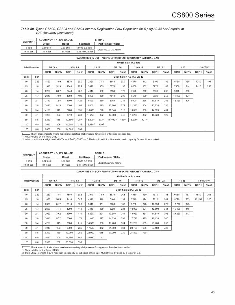
Table 50. Types CS820, CS823 and CS824 Internal Registration Flow Capacities for 5 psig / 0.34 bar Setpoint at 10% Accuracy (continued)
SETPOINTACCURACY: + / - 10% GAUGE SPRING
Droop Boost Set Range Part Number / Color5 psig -0.50 psig 0.50 psig 2.5 to 5.5 psig
GE30343X012 / Yellow0.34 bar -34 mbar 34 mbar 0.17 to 0.38 bar
CAPACITIES IN SCFH / Nm3/h OF 0.6 SPECIFIC GRAVITY NATURAL GAS
Inlet Pressure
Orifice Size, In. / mm
1/4 / 6.4 3/8 / 9.5 1/2 / 13 5/8 / 16 3/4 / 19 7/8 / 22 1 / 25 1-3/8 / 35(1)(2)
SCFH Nm3/h SCFH Nm3/h SCFH Nm3/h SCFH Nm3/h SCFH Nm3/h SCFH Nm3/h SCFH Nm3/h SCFH Nm3/h
psig bar Body Size: 2 in. / DN 50
10 0.69 1280 34.4 1880 50.5 2940 78.9 3530 94.8 4830 130 4970 133 6060 163 7680 206
15 1.0 1880 50.5 2410 64.7 4310 116 5160 139 7240 194 7610 204 9790 263 12,150 326
20 1.4 2300 61.7 3310 88.9 5610 151 6900 185 9230 248 10,390 279 12,770 343
25 1.7 2660 71.4 4200 113 7040 189 8220 221 10,950 294 12,690 341 15,480 416
30 2.1 2950 79.2 4990 134 8220 221 10,580 284 13,060 351 14,810 398 19,260 517
40 2.8 3640 97.7 6360 171 11,080 297 14,630 393 17,710 475 20,120 540
50 3.4 4280 115 8000 215 14,370 386 18,760 504 21,200 569 23,760 638
60 4.1 4940 133 9900 266 17,590 472 21,760 584 23,760 638 27,480 738
80 5.5 6290 169 13,260 356 22,900 615 27,200 730 27,200 730
100 6.9 7650 205 16,380 440 28,030 753
125 8.6 9390 252 20,030 538
Blank areas indicate where maximum operating inlet pressure for a given orifice size is exceeded.1. Not available on the Type CS823.2. Type CS824 exhibits a 20% reduction in capacity for indicated orifice size. Multiply listed values by a factor of 0.8.
SETPOINTACCURACY: + / - 10% GAUGE SPRING
Droop Boost Set Range Part Number / Color5 psig -0.50 psig 0.50 psig 2.5 to 5.5 psig
GE30343X012 / Yellow0.34 bar -34 mbar 34 mbar 0.17 to 0.38 bar
CAPACITIES IN SCFH / Nm3/h OF 0.6 SPECIFIC GRAVITY NATURAL GAS
Inlet Pressure
Orifice Size, In. / mm
1/4 / 6.4 3/8 / 9.5 1/2 / 13 5/8 / 16 3/4 / 19 7/8 / 22 1 / 25 1-3/8 / 35(1)
SCFH Nm3/h SCFH Nm3/h SCFH Nm3/h SCFH Nm3/h SCFH Nm3/h SCFH Nm3/h SCFH Nm3/h SCFH Nm3/h
psig bar Body Size: 1-1/2 in. / DN 40
10 0.69 1450 38.9 1870 50.2 2650 71.1 3640 97.7 4170 112 5190 139 5760 155 7240 194
15 1.0 1910 51.3 2640 70.9 3920 105 5070 136 6050 162 6970 187 7960 214 9410 253
20 1.4 2260 60.7 3440 92.3 4910 132 6530 175 7520 202 8800 236 9670 260
25 1.7 2640 70.9 4060 109 5920 159 7510 202 8570 230 9620 258 11,320 304
30 2.1 2710 72.8 4700 126 6690 180 8750 235 9900 266 10,670 286 12,160 326
40 2.8 3410 91.5 6000 161 8000 215 10,100 271 11,330 304 13,220 355
50 3.4 4100 110 7260 195 10,070 270 11,540 310 13,030 350 14,920 401
60 4.1 4950 133 8610 231 11,250 302 12,880 346 14,220 382 15,630 420
80 5.5 6260 168 10,690 287 13,890(2) 373(2) 15,400(2) 413(2) 16,290(2) 437(2)
100 6.9 7660 206 12,590 338 15,980(2) 429(2)
125 8.6 9300 250 14,860 399
Blank areas indicate where maximum operating inlet pressure for a given orifice size is exceeded.1. Not available on the Type CS823.2. When stabilizer cartridge used with Types CS800, CS803 or CS804 could exhibit a 10% reduction in capacity for conditions marked.
43
CS800 Series

Table 51. Types CS820, CS823 and CS824 Internal Registration Flow Capacities for 5 psig / 0.34 bar Setpoint at 20% Accuracy
SETPOINTACCURACY: + / - 20% GAUGE SPRING
Droop Boost Set Range Part Number / Color5 psig -1.0 psig 1.0 psig 2.5 to 5.5 psig
GE30343X012 / Yellow0.34 bar -69 mbar 69 mbar 0.17 to 0.38 bar
SETPOINTACCURACY: + / - 20% GAUGE SPRING
Droop Boost Set Range Part Number / Color5 psig -1.0 psig 1.0 psig 2.5 to 5.5 psig
GE30343X012 / Yellow0.34 bar -69 mbar 69 mbar 0.17 to 0.38 bar
CAPACITIES IN SCFH / Nm3/h OF 0.6 SPECIFIC GRAVITY NATURAL GAS
Inlet Pressure
Orifice Size, In. / mm
1/4 / 6.4 3/8 / 9.5 1/2 / 13 5/8 / 16 3/4 / 19 7/8 / 22 1 / 25 1-3/8 / 35(1)
SCFH Nm3/h SCFH Nm3/h SCFH Nm3/h SCFH Nm3/h SCFH Nm3/h SCFH Nm3/h SCFH Nm3/h SCFH Nm3/h
psig bar Body Size: 1-1/4 in. / DN 32
10 0.69 1589 42.6 2944 79.0 4608 124 5969 160 7119 191 8091 217 8752 235 10,425 280
15 1.0 1924 51.7 4008 108 6266 168 7801 209 9123 245 10,155 273 10,445 280 12,236 328
20 1.4 2296 61.6 4918 132 7829 210 9290 249 10,466 281 11,400 306 11,726 315
25 1.7 2640 70.9 5700 153 8758 235 10,533 283 11,720 315 12,244 329 12,792 343
30 2.1 2943 79.0 6401 172 9899 266 11,550 310 12,645 339 12,897 346 13,151 353
40 2.8 3634 97.5 7705 207 11,373 305 12,383 332 13,484 362 14,071 378
50 3.4 4319 116 9211 247 12,418 333 13,496 362 14,131 379 14,612 392
60 4.1 4924 132 10,598 285 13,265 356 14,149 380 14,474 389 15,608 419
80 5.5 6250 168 13,171 354 14,144 380 15,100 405 15,172 407
100 6.9 7670 206 14,231 382 14,720 395
125 8.6 9233 248 15,079 405
Blank areas indicate where maximum operating inlet pressure for a given orifice size is exceeded.1. Not available on the Type CS823.
CAPACITIES IN SCFH / Nm3/h OF 0.6 SPECIFIC GRAVITY NATURAL GAS
Inlet Pressure
Orifice Size, In. / mm
1/4 / 6.4 3/8 / 9.5 1/2 / 13 5/8 / 16 3/4 / 19 7/8 / 22 1 / 25 1-3/8 / 35(1)
SCFH Nm3/h SCFH Nm3/h SCFH Nm3/h SCFH Nm3/h SCFH Nm3/h SCFH Nm3/h SCFH Nm3/h SCFH Nm3/h
psig bar Body Size: 1-1/2 in. / DN 40
10 0.69 1530 41.1 2710 72.8 4370 117 5880 158 6680 179 8470 227 9740 262 12,040 323
15 1.0 1960 52.6 3750 101 6250 168 7870 211 9620 258 11,330 304 12,580 338 15,210 408
20 1.4 2310 62.0 4720 127 7850 211 10,140 272 11,480 308 13,870 372 14,580 391
25 1.7 2640 70.9 5520 148 9360 251 10,840 291 13,070 351 15,030 404 16,530 444
30 2.1 2880 77.3 6390 172 10,570 284 12,760 343 14,620 393 16,620 446 16,990 456
40 2.8 3560 95.6 7870 211 12,500 336 15,170 407 16,890 453 19,270 517
50 3.4 4240 114 9360 251 14,840 398 16,650 447 18,310 492 21,270 571
60 4.1 4950 133 11,000 295 16,380 440 17,530 471 19,970 536 22,640 608
80 5.5 6310 169 13,840 372 19,090 513 20,400 548 22,710 610
100 6.9 7690 206 16,280 437 21,380 574
125 8.6 9390 252 19,280 518
Blank areas indicate where maximum operating inlet pressure for a given orifice size is exceeded.1. Not available on the Type CS823.
44
CS800 Series
- continued -

Table 51. Types CS820, CS823 and CS824 Internal Registration Flow Capacities for 5 psig / 0.34 bar Setpoint at 20% Accuracy (continued)
SETPOINTACCURACY: + / - 20% GAUGE SPRING
Droop Boost Set Range Part Number / Color5 psig -1.0 psig 1.0 psig 2.5 to 5.5 psig
GE30343X012 / Yellow0.34 bar -69 mbar 69 mbar 0.17 to 0.38 bar
CAPACITIES IN SCFH / Nm3/h OF 0.6 SPECIFIC GRAVITY NATURAL GAS
Inlet PressureOrifice Size, In. / mm
1/4 / 6.4 3/8 / 9.5 1/2 / 13 5/8 / 16 3/4 / 19 7/8 / 22 1 / 25 1-3/8 / 35(1)(2)
SCFH Nm3/h SCFH Nm3/h SCFH Nm3/h SCFH Nm3/h SCFH Nm3/h SCFH Nm3/h SCFH Nm3/h SCFH Nm3/hpsig bar Body Size: 2 in. / DN 5010 0.69 1500 40.3 2840 76.2 4780 128 5970 160 8000 215 9400 252 10,550 283 13,590 36515 1.0 1970 52.9 3870 104 6960 187 8540 229 11,770 316 12,740 342 15,830 425 19,260 51720 1.4 2330 62.6 4700 126 8600 231 10,760 289 14,810 398 16,600 446 19,810 53225 1.7 2660 71.4 5700 153 10,060 270 13,260 356 17,350 466 19,690 529 21,840 58630 2.1 2970 79.7 6500 175 11,660 313 15,530 417 20,540 551 20,950 562 24,770 66540 2.8 3670 98.5 7910 212 14,470 389 20,460 549 24,480 657 25,870 69550 3.4 4320 116 9340 251 17,690 475 23,180 622 29,880 802 30,750 82660 4.1 5010 135 11,120 299 20,100 540 27,820 747 31,780 853 33,840 90980 5.5 6340 170 13,740 369 25,800 693 34,910 937 36,270 974
100 6.9 7710 207 16,900 454 31,450 844125 8.6 9410 253 20,580 553
Blank areas indicate where maximum operating inlet pressure for a given orifice size is exceeded.1. Not available on the Type CS823.2. Type CS824 exhibits a 20% reduction in capacity for indicated orifice size. Multiply listed values by a factor of 0.8.
Table 52. Types CS850 and CS854 Internal Registration Flow Capacities for 7 psig / 0.48 bar Setpoint at 10% Accuracy
SETPOINTACCURACY: + / - 10% GAUGE SPRING
Droop Boost Set Range Part Number / Color7 psig -0.7 psig 0.7 psig 5 to 10 psig GE30344X012 / Green with
White Stripe0.48 bar -48 mbar 48 mbar 345 to 690 mbar
psig bar Body Size: 2 in. / DN 5010 0.69 750 20.1 1290 34.6 1750 47.0 2140 57.4 2640 70.9 3170 85.1 3550 95.3 4540 12215 1.0 1710 45.9 1950 52.3 2740 73.6 3530 94.8 4050 109 4750 128 5860 157 7640 20520 1.4 2150 57.7 2500 67.1 3440 92.3 4470 120 5500 148 6600 177 7850 21125 1.7 2380 63.9 3070 82.4 4190 113 5390 145 6150 165 8150 219 9360 25130 2.1 2870 77.0 3570 95.8 4900 132 6300 169 7430 200 9980 268 11,640 31340 2.8 3540 95.0 4630 124 6570 176 8610 231 10,430 280 12,830 34450 3.4 4210 113 5530 149 7570 203 10,550 283 12,380 332 16,070 43160 4.1 4790 129 6690 180 9970 268 12,780 343 14,680 394 19,320 51980 5.5 6070 163 8740 235 14,170 380 16,720 449 17,930 481
100 6.9 7690 206 11,310 304 18,060 485125 8.6 9220 248 14,520 390
Blank areas indicate where maximum operating inlet pressure for a given orifice size is exceeded.
CAPACITIES IN SCFH / Nm3/h OF 0.6 SPECIFIC GRAVITY NATURAL GAS
Inlet Pressure
Orifice Size, In. / mm1/4 / 6.4 3/8 / 9.5 1/2 / 13 5/8 / 16 3/4 / 19 7/8 / 22 1 / 25 1-3/8 / 35
SCFH Nm3/h SCFH Nm3/h SCFH Nm3/h SCFH Nm3/h SCFH Nm3/h SCFH Nm3/h SCFH Nm3/h SCFH Nm3/hpsig bar Body Size: 1-1/2 in. / DN 4010 0.69 1140 30.6 1250 33.6 1710 45.9 2030 54.5 2550 68.5 3140 84.3 3370 90.5 4290 11515 1.0 1590 42.7 1810 48.6 2660 71.4 3150 84.6 3840 103 4490 121 5480 147 6860 18420 1.4 2010 54.0 2460 66.0 3400 91.3 4170 112 4590 123 5710 153 6740 18125 1.7 2400 64.4 2980 80.0 4190 113 5030 135 5970 160 6790 182 7800 20930 2.1 2750 73.8 3450 92.6 4800 129 5840 157 7050 189 7890 212 9070 24440 2.8 3420 91.8 4380 118 6180 166 7350 197 8310 223 9760 26250 3.4 3990 107 5270 142 7450 200 8900 239 11,530 310 11,530 31060 4.1 4730 127 6220 167 8470 227 10,410 280 11,550 310 13,300 35780 5.5 5950 160 7700 207 11,070 297 13,150 353 15,300 411
100 6.9 7300 196 9480 255 12,400 333125 8.6 8660 233 11,250 302
45
CS800 Series

Figure 20. Type CS820IQ High Capacity Relief Curves (Blocked Open per Orifice Size) at 5 psig / 0.34 bar Set Pressure
INLET PRESSURE, psig / bar
HIGH CAPACITY 2-1/2 NPT VENT SIZE
OU
TLET
PR
ESSU
RE,
psi
g / m
bar
0 10 / 0.69
10 / 690
9.5 / 655
9 / 621
8.5 / 586
8 / 552
7.5 / 517
7 / 483
6.5 / 448
6 / 414
5.5 / 379
5 / 345
20 / 1.4
30 / 2.1
40 / 2.8
50 / 3.4
60 / 4.1
70 / 4.8
80 / 5.5
90 / 6.2
100 / 6.9
110 / 7.6
120 / 8.3
1-3/8 in. /35 mmORIFICE
1 in. /25 mmORIFICE
7/8 in. /22 mmORIFICE
3/4 in. /19 mmORIFICE
5/8 in. /16 mmORIFICE
1/2 in. /13 mmORIFICE
3/8 in. /9.5 mmORIFICE
1/4 in. /6.4 mmORIFICE
Figure 19. Type CS820IR Relief Curves (Blocked Open per Orifice Size) at 5 psig / 0.34 bar Set Pressure
INLET PRESSURE, psig / bar
1 NPT VENT SIZE
OU
TLET
PR
ESSU
RE,
psi
g / m
bar
0 10 / 0.69
10 / 690
9.5 / 655
9 / 621
8.5 / 586
8 / 552
7.5 / 517
7 / 483
6.5 / 448
6 / 414
5.5 / 379
5 / 34520 / 1.4
30 / 2.1
40 / 2.8
50 / 3.4
60 / 4.1
70 / 4.8
80 / 5.5
90 / 6.2
100 / 6.9
110 / 7.6
120 / 8.3
1-3/8 in. /35 mmORIFICE
7/8 in. /22 mmORIFICE
3/4 in. /19 mmORIFICE
5/8 in. /16 mmORIFICE
1/2 in. /13 mmORIFICE
3/8 in. /9.5 mmORIFICE
1 in. /25 mmORIFICE
1/4 in. /6.4 mmORIFICE
46
CS800 Series

Table 53. Types CS850 and CS854 Internal Registration Flow Capacities for 7 psig / 0.48 bar Setpoint at 20% Accuracy
SETPOINTACCURACY: + / - 20% GAUGE SPRING
Droop Boost Set Range Part Number / Color7 psig -1.4 psig 1.4 psig 5 to 10 psig GE30344X012 / Green with
White Stripe0.48 bar -0.10 bar 0.10 bar 345 to 690 mbar
psig bar Body Size: 2 in. / DN 50
10 0.69 1070 28.7 2230 59.9 3160 84.8 4040 109 4980 134 5880 158 6910 186 8860 238
15 1.0 1820 48.9 3180 85.4 4610 124 6210 167 7360 198 9080 244 10,790 290 14,360 386
20 1.4 2300 61.7 4110 110 6040 162 8060 216 9940 267 11,680 314 13,270 356
25 1.7 2640 70.9 4970 133 7490 201 10,160 273 11,780 316 13,930 374 16,610 446
30 2.1 2990 80.3 5710 153 8680 233 11,550 310 14,060 377 16,300 438 19,820 532
40 2.8 3670 98.5 7360 198 11,440 307 14,910 400 18,130 487 21,300 572
50 3.4 4350 117 8840 237 13,780 370 18,390 494 21,560 579 25,210 677
60 4.1 5010 135 10,560 284 17,310 465 21,630 581 25,080 673 28,560 767
80 5.5 6320 170 13,510 363 22,290 598 25,840 694 27,620 742
100 6.9 7750 208 16,590 445 26,950 724
125 8.6 9400 252 19,680 528
Blank areas indicate where maximum operating inlet pressure for a given orifice size is exceeded.
CAPACITIES IN SCFH / Nm3/h OF 0.6 SPECIFIC GRAVITY NATURAL GAS
Inlet Pressure
Orifice Size, In. / mm
1/4 / 6.4 3/8 / 9.5 1/2 / 13 5/8 / 16 3/4 / 19 7/8 / 22 1 / 25 1-3/8 / 35
SCFH Nm3/h SCFH Nm3/h SCFH Nm3/h SCFH Nm3/h SCFH Nm3/h SCFH Nm3/h SCFH Nm3/h SCFH Nm3/h
psig bar Body Size: 1-1/2 in. / DN 40
10 0.69 1350 36.2 2090 56.1 3100 83.2 3850 103 4760 128 5780 155 6270 168 8620 231
15 1.0 1870 50.2 3060 82.1 4780 128 5830 157 6990 188 8540 229 9610 258 12,270 329
20 1.4 2190 58.8 3930 106 5970 160 7450 200 8850 238 10,690 287 12,280 330
25 1.7 2550 68.5 4810 129 7400 199 8970 241 10,630 285 12,880 346 13,610 365
30 2.1 2900 77.9 5520 148 8440 227 10,320 277 12,400 333 14,340 385 15,400 413
40 2.8 3610 96.9 7030 189 10,610 285 12,970 348 15,010 403 17,140 460
50 3.4 4260 114 8370 225 12,500 336 15,010 403 18,020 484 19,120 513
60 4.1 4880 131 9850 264 14,320 384 16,940 455 19,130 514 20,780 558
80 5.5 6250 168 12,680 340 17,670 474 19,700 529 21,670 582
100 6.9 7610 204 15,170 407 19,700 529
125 8.6 9290 249 17,740 476
47
CS800 Series
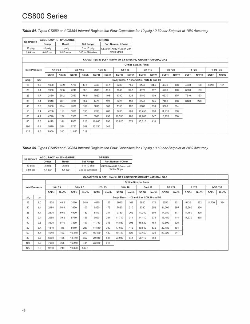
SETPOINTACCURACY: +/- 10% GAUGE SPRING
Droop Boost Set Range Part Number / Color10 psig -1 psig 1 psig 5 to 10 psig GE30344X012 / Green with
White Stripe0.69 bar -0.07 bar 0.07 mbar 345 to 690 mbar
CAPACITIES IN SCFH / Nm3/h OF 0.6 SPECIFIC GRAVITY NATURAL GAS
Inlet Pressure
Orifice Size, In. / mm
1/4 / 6.4 3/8 / 9.5 1/2 / 13 5/8 / 16 3/4 / 19 7/8 / 22 1 / 25 1-3/8 / 35
SCFH Nm3/h SCFH Nm3/h SCFH Nm3/h SCFH Nm3/h SCFH Nm3/h SCFH Nm3/h SCFH Nm3/h SCFH Nm3/h
psig bar Body Sizes: 1-1/2 and 2 in. / DN 40 and 50
15 1.0 1300 34.9 1780 47.9 2460 66.1 2780 74.7 3140 84.2 4040 108 4040 108 6010 161
20 1.4 1960 52.6 2240 60.1 2980 80.0 3640 97.5 4370 117 5230 140 6060 163
25 1.7 2430 65.2 2860 76.9 4020 108 4780 128 5180 139 6530 175 7210 193
30 2.1 2910 78.1 3210 86.2 4470 120 5720 153 6540 175 7400 198 8420 226
40 2.8 3560 95.4 4080 109 6090 163 7150 192 8680 233 9860 264
50 3.4 4230 113 5020 135 7760 208 9730 261 10,750 288 11,210 300
60 4.1 4790 129 6360 170 8900 238 10,530 282 12,960 347 13,720 368
80 5.5 6110 164 7950 213 10,840 290 13,920 373 15,610 418
100 6.9 7610 204 9730 261 12,780 343
125 8.6 8960 240 11,890 319
Table 54. Types CS850 and CS854 Internal Registration Flow Capacities for 10 psig / 0.69 bar Setpoint at 10% Accuracy
SETPOINTACCURACY: +/- 20% GAUGE SPRING
Droop Boost Set Range Part Number / Color10 psig -2 psig 2 psig 5 to 10 psig GE30344X012 / Green with
White Stripe0.69 bar -1.4 bar 1.4 bar 345 to 690 mbar
Table 55. Types CS850 and CS854 Internal Registration Flow Capacities for 10 psig / 0.69 bar Setpoint at 20% Accuracy
CAPACITIES IN SCFH / Nm3/h OF 0.6 SPECIFIC GRAVITY NATURAL GAS
Inlet Pressure
Orifice Size, In. / mm
1/4 / 6.4 3/8 / 9.5 1/2 / 13 5/8 / 16 3/4 / 19 7/8 / 22 1 / 25 1-3/8 / 35
SCFH Nm3/h SCFH Nm3/h SCFH Nm3/h SCFH Nm3/h SCFH Nm3/h SCFH Nm3/h SCFH Nm3/h SCFH Nm3/h
psig bar Body Sizes: 1-1/2 and 2 in. / DN 40 and 50
15 1.0 1820 48.8 3160 84.8 4670 125 6050 162 6650 178 8250 221 9420 252 11,730 314
20 1.4 2190 58.8 3850 103 6450 173 7820 210 9380 251 11,000 295 12,560 336
25 1.7 2570 69.0 4920 132 8110 217 9780 262 11,240 301 14,080 377 14,750 395
30 2.1 2950 79.2 5780 155 9090 244 11,710 314 14,110 378 15,450 414 17,370 465
40 2.8 3620 97.0 7330 197 11,740 315 14,830 398 16,820 451 19,590 525
50 3.4 4310 116 8910 239 14,510 389 17,600 472 19,840 532 22,180 594
60 4.1 4940 133 10,410 279 16,430 440 19,720 528 23,450 628 23,920 641
80 5.5 6260 168 13,140 352 20,040 537 23,940 641 28,110 753
100 6.9 7660 205 16,210 434 23,050 618
125 8.6 9290 249 19,320 517.8
48
CS800 Series

Table 56. Types CS800, CS803 and CS804 External Registration Flow Capacities for 7 in. w.c. / 17 mbar Setpoint
SETPOINTACCURACY SPRING
Droop Boost Set Range Part Number / Color7 in. w.c. -2 in. w.c. 2 in. w.c. 5.5 to 8.5 in. w.c.
GE30338X012 / Black17 mbar -5 mbar 5 mbar 13 to 21 mbar
psig bar Body Sizes: 1-1/2 and 2 in. / DN 40 and 500.4 0.03 550 14.8 780 20.9 1090 29.3 1000 26.8 1390 37.3 1640 44.0 1780 47.80.51 0.04 360 9.7 630 16.9 930 25.0 1100 29.5 1530 41.1 1530 41.1 1940 52.1 2400 64.4
1 0.07 500 13.4 830 22.3 1290 34.6 1730 46.4 1980 53.2 2320 62.3 2860 76.8 3780 1022 0.14 720 19.3 1330 35.7 2010 54.0 2550 68.5 3260 87.5 3740 100 4360 117 5930 1593 0.21 870 23.4 1650 44.3 2500 67.1 3180 85.4 4130 111 4760 128 5250 141 7110 1915 0.34 1120 30.1 2070 55.6 3410 91.5 4380 118 5620 151 6400 172 7500 201 9370 252
10 0.69 1480 39.7 2990 80.3 5010 135 6480 174 8420 226 9820 264 11,600 311 14,600 39215 1.0 1810 48.6 3710 99.6 6410 172 8320 223 10,800 290 12,770 343 15,130 406 19,610 52620 1.4 2170 58.3 4560 122 7720 207 10,750 289 13,660 367 15,080 405 18,520 49725 1.7 2520 67.7 5320 143 9030 242 12,220 328 16,340 439 18,630 500 21,950 58930 2.1 2770 74.4 5990 161 10,440 280 13,770 370 17,790 478 20,350 54640 2.8 3400 91.3 7360 198 12,490 335 16,720 449 20,320 546 25,650 68950 3.4 4010 108 8700 234 14,510 390 18,750 503 24,220 650 26,390 70960 4.1 4630 124 10,110 271 16,810 451 22,130 594 26,490 71180 5.5 5960 160 12,550 337 19,580 526
100 6.9 7280 195 15,030 404 22,540 605125 8.6 8150 219 16,990 456
Black areas show where indicated droop/boost would be exceeded regardless of capacity. Blank areas indicate where maximum operating inlet pressure for a given orifice size is exceeded.1. Not available on the Type CS803.
CAPACITIES IN SCFH / Nm3/h OF 0.6 SPECIFIC GRAVITY NATURAL GAS
Inlet PressureOrifice Size, In. / mm
1/4 / 6.4 3/8 / 9.5 1/2 / 13 5/8 / 16 3/4 / 19 7/8 / 22 1 / 25 1-3/8 / 35(1)
SCFH Nm3/h SCFH Nm3/h SCFH Nm3/h SCFH Nm3/h SCFH Nm3/h SCFH Nm3/h SCFH Nm3/h SCFH Nm3/h
Table 57. Types CS800, CS803 and CS804 External Registration Flow Capacities for 10 in. w.c. / 25 mbar Setpoint
SETPOINTACCURACY SPRING
Droop Boost Set Range Part Number / Color10 in. w.c. -2 in. w.c. 2 in. w.c. 5.5 to 8.5 in. w.c.
GE30339X012 / Purple25 mbar -5 mbar 5 mbar 13 to 21 mbar
psig bar Body Sizes: 1-1/2 and 2 in. / DN 40 and 500.51 0.04 310 8.3 560 15.0 640 17.2 990 26.6 1290 34.6 1250 33.6 1250 33.6 1970 52.9
1 0.07 470 12.6 750 20.1 1130 30.3 1430 38.4 1850 49.7 2210 59.3 2520 67.7 3530 94.82 0.14 690 18.5 1250 33.6 1530 41.1 1910 51.3 2880 77.3 3560 95.6 3750 101 5110 1373 0.21 850 22.8 1540 41.3 2260 60.7 2860 76.8 3690 99.1 4350 117 4690 126 6320 1705 0.34 1080 29.0 2050 55.0 3090 83.0 3850 103 4810 129 5850 157 6860 184 8180 220
10 0.69 1420 38.1 2590 69.5 4470 120 5460 147 7370 198 8340 224 10,130 272 13,030 35015 1.0 1750 47.0 3500 94.0 5880 158 7500 201 9380 252 11,120 299 13,700 368 18,810 50520 1.4 2090 56.1 4200 113 7260 195 9470 254 11,860 318 14,270 383 16,060 43125 1.7 2450 65.8 4950 133 8690 233 11,450 307 14,720 395 17,400 467 18,860 50630 2.1 2790 74.9 5600 150 10,170 273 12,560 337 16,420 441 19,700 52940 2.8 3390 91.0 6850 184 12,420 333 15,470 415 20,510 551 24,130 64850 3.4 4010 108 8200 220 14,090 378 17,960 482 23,020 618 29,010 77960 4.1 4620 124 9500 255 16,410 441 19,770 531 26,280 70680 5.5 5920 159 11,900 320 19,050 511
100 6.9 7200 193 14,270 383 21,960 590125 8.6 8080 217 15,680 421
Blank areas indicate where maximum operating inlet pressure for a given orifice size is exceeded.1. Not available on the Type CS803.
CAPACITIES IN SCFH / Nm3/h OF 0.6 SPECIFIC GRAVITY NATURAL GAS
Inlet PressureOrifice Size, In. / mm
1/4 / 6.4 3/8 / 9.5 1/2 / 13 5/8 / 16 3/4 / 19 7/8 / 22 1 / 25 1-3/8 / 35(1)
SCFH Nm3/h SCFH Nm3/h SCFH Nm3/h SCFH Nm3/h SCFH Nm3/h SCFH Nm3/h SCFH Nm3/h SCFH Nm3/h
49
CS800 Series

Table 58. Types CS800, CS803 and CS804 External Registration Flow Capacities for 14 in. w.c. / 35 mbar Setpoint
SETPOINTACCURACY SPRING
Droop Boost Set Range Part Number / Color14 in. w.c. -2 in. w.c. 2 in. w.c. 10 to 16 in. w.c.
GE30340X012 / White35 mbar -5 mbar 5 mbar 25 to 40 mbar
psig bar Body Sizes: 1-1/2 and 2 in. / DN 40 and 50
1 0.07 430 11.5 520 14.0 1210 32.5 1210 32.5 1290 34.6 1540 41.3 1790 48.1 2510 67.4
2 0.14 630 16.9 990 26.6 1690 45.4 2010 54.0 2440 65.5 2900 77.9 3350 89.9 4500 121
3 0.21 770 20.7 1350 36.2 1870 50.2 2540 68.2 2890 77.6 3730 100 4230 114 5660 152
5 0.34 1030 27.7 1800 48.3 2760 74.1 3280 88.1 4020 108 5320 143 5730 154 7160 192
10 0.69 1380 37.0 2560 68.7 4000 107 5110 137 6320 170 7700 207 8530 229 13,160 353
15 1.0 1700 45.6 3220 86.4 4980 134 6400 172 8180 220 10,270 276 11,690 314 19,100 513
20 1.4 1970 52.9 4040 109 6270 168 8110 218 10,620 285 15,320 411 17,550 471
25 1.7 2340 62.8 4890 131 7810 210 9570 257 12,530 336 18,870 507 20,710 556
30 2.1 2710 72.8 5320 143 8280 222 10,890 292 13,070 351 19,710 529
40 2.8 3300 88.6 6900 185 10,980 295 13,280 357 16,560 444 26,440 710
50 3.4 3890 104 8290 223 12,990 349 16,060 431 18,020 484 30,650 823
60 4.1 4490 121 9710 261 15,400 413 18,340 492 21,170 568
80 5.5 5770 155 12,450 334 18,900 507
100 6.9 7000 188 15,030 404 21,320 572
125 8.6 7900 212 16,680 448
Blank areas indicate where maximum operating inlet pressure for a given orifice size is exceeded.1. Not available on the Type CS803.
CAPACITIES IN SCFH / Nm3/h OF 0.6 SPECIFIC GRAVITY NATURAL GAS
Inlet Pressure
Orifice Size, In. / mm
1/4 / 6.4 3/8 / 9.5 1/2 / 13 5/8 / 16 3/4 / 19 7/8 / 22 1 / 25 1-3/8 / 35(1)
SCFH Nm3/h SCFH Nm3/h SCFH Nm3/h SCFH Nm3/h SCFH Nm3/h SCFH Nm3/h SCFH Nm3/h SCFH Nm3/h
Table 59. Types CS800, CS803 and CS804 External Registration Flow Capacities for 1 psig / 0.07 bar Setpoint
SETPOINTACCURACY SPRING
Droop Boost Set Range Part Number / Color1 psig -5.5 in. w.c. 5.5 in. w.c. 14 to 30 in. w.c.
GE30341X012 / Dark Green0.07 bar -14 mbar 14 mbar 35 to 75 mbar
psig bar Body Sizes: 1-1/2 and 2 in. / DN 40 and 50
2 0.14 680 18.3 1090 29.3 1830 49.1 2540 68.2 2950 79.2 3390 91.0 4140 111 6030 162
3 0.21 870 23.4 1500 40.3 2530 67.9 3360 90.2 4300 115 4870 131 5700 153 7310 196
5 0.34 1170 31.4 2050 55.0 3430 92.1 4690 126 6110 164 7000 188 8210 220 9760 262
10 0.69 1490 40.0 2960 79.5 4840 130 6550 176 8320 223 9480 255 11,380 306 14,700 395
15 1.0 1810 48.6 3790 102 6610 177 8740 235 10,590 284 11,840 318 13,980 375 20,000 537
20 1.4 2130 57.2 4920 132 7750 208 10,220 274 12,360 332 14,930 401 16,240 436
25 1.7 2580 69.3 5590 150 9070 244 11,790 317 14,230 382 17,970 482 18,370 493
30 2.1 2900 77.9 6570 176 10,070 270 13,200 354 16,450 442 19,880 534 22,620 607
40 2.8 3640 97.7 7830 210 12,890 346 15,860 426 19,200 515 20,760 557
50 3.4 4420 119 9360 251 15,480 416 18,380 493 22,670 609 24,280 652
60 4.1 5100 137 10,910 293 18,120 486 21,070 566 24,680 663 26,750 718
80 5.5 6460 173 13,140 353 20,770 558 23,970 644 27,780 746
100 6.9 7930 213 16,420 441 23,090 620
125 8.6 8730 234 19,710 529
Blank areas indicate where maximum operating inlet pressure for a given orifice size is exceeded.1. Not available on the Type CS803.
CAPACITIES IN SCFH / Nm3/h OF 0.6 SPECIFIC GRAVITY NATURAL GAS
Inlet Pressure
Orifice Size, In. / mm
1/4 / 6.4 3/8 / 9.5 1/2 / 13 5/8 / 16 3/4 / 19 7/8 / 22 1 / 25 1-3/8 / 35(1)
SCFH Nm3/h SCFH Nm3/h SCFH Nm3/h SCFH Nm3/h SCFH Nm3/h SCFH Nm3/h SCFH Nm3/h SCFH Nm3/h
50
CS800 Series

Table 60. Types CS820, CS823 and CS824 External Registration Flow Capacities for 2 psig / 138 mbar Setpoint at 20% Accuracy
SETPOINTACCURACY SPRING
Droop Boost Set Range Part Number / Color2 psig -0.40 psig 0.40 psig 1 to 2.5 psig
GE30342X012 / Dark Blue138 mbar -28 mbar 28 mbar 69 to 170 mbar
psig bar Body Sizes: 1-1/2 and 2 in. / DN 40 and 50
3 0.21 760 20.4 1220 32.8 1820 48.9 2780 74.6 2780 74.6 4180 112 5360 144 5540 149
5 0.34 1080 29.0 1770 47.5 2880 77.3 3710 99.6 4840 130 5570 150 6950 187 8570 230
10 0.69 1460 39.2 2560 68.7 4400 118 6330 170 7400 197 8750 235 9180 246 12,710 341
15 1.0 1760 47.2 3560 95.6 5540 149 7870 211 9590 257 11,280 303 11,890 319 15,220 409
20 1.4 2090 56.1 4310 116 6680 179 9610 258 11,940 321 13,420 360 14,300 384
25 1.7 2350 63.1 5100 137 7600 204 10,780 289 13,440 361 14,020 376 15,510 416
30 2.1 2710 72.8 5760 155 8980 241 12,410 333 15,040 404 15,770 423 17,220 462
40 2.8 3390 91.0 7290 196 10,560 284 14,810 398 16,840 452 18,260 490
50 3.4 3970 107 8530 229 12,490 335 16,790 451 18,370 493 19,490 523
60 4.1 4570 123 9930 267 14,050 377 18,570 499 19,310 518 21,120 567
80 5.5 5880 158 12,420 333 16,150 434 20,330 546 21,450 576
100 6.9 7250 195 14,670 394 18,850 506
125 8.6 8960 241 16,450 442
Blank areas indicate where maximum operating inlet pressure for a given orifice size is exceeded.1. Not available on the Type CS823.
CAPACITIES IN SCFH / Nm3/h OF 0.6 SPECIFIC GRAVITY NATURAL GAS
Inlet Pressure
Orifice Size, In. / mm
1/4 / 6.4 3/8 / 9.5 1/2 / 13 5/8 / 16 3/4 / 19 7/8 / 22 1 / 25 1-3/8 / 35(1)
SCFH Nm3/h SCFH Nm3/h SCFH Nm3/h SCFH Nm3/h SCFH Nm3/h SCFH Nm3/h SCFH Nm3/h SCFH Nm3/h
Table 61. Types CS820, CS823 and CS824 External Registration Flow Capacities for 5 psig / 345 mbar Setpoint at 20% Accuracy
SETPOINTACCURACY SPRING
Droop Boost Set Range Part Number / Color5 psig -1 psig 1 psig 2.5 to 5.5 psig
GE30343X012 / Yellow345 mbar -0.07 mbar 69 mbar 170 to 380 mbar
psig bar Body Sizes: 1-1/2 and 2 in. / DN 40 and 50
10 0.69 1430 38.4 2320 62.3 4370 117 4780 128 5920 159 7360 198 8670 233 10,820 291
15 1.0 1800 48.3 3370 90.5 5370 144 7030 189 8520 229 11,130 299 11,870 319 15,610 419
20 1.4 2120 56.9 4510 121 6640 178 8920 240 11,730 315 13,420 360 15,360 412
25 1.7 2430 65.2 5340 143 7770 209 11,420 307 14,150 380 15,880 426 18,530 497
30 2.1 2730 73.3 5960 160 9120 245 13,180 354 15,890 427 17,100 459 20,070 539
40 2.8 3410 91.5 7210 194 11,410 306 16,620 446 18,800 505 19,890 534
50 3.4 4040 109 8640 232 13,540 364 17,940 482 21,260 571 24,110 647
60 4.1 4560 122 10,140 272 15,530 417 21,730 583 24,520 658 26,500 711
80 5.5 5880 158 12,840 345 20,480 550 25,360 681 29,700 797
100 6.9 7230 194 15,560 418 23,710 637
125 8.6 8910 239 20,320 546
Blank areas indicate where maximum operating inlet pressure for a given orifice size is exceeded.1. Not available on the Type CS823.
CAPACITIES IN SCFH / Nm3/h OF 0.6 SPECIFIC GRAVITY NATURAL GAS
Inlet Pressure
Orifice Size, In. / mm
1/4 / 6.4 3/8 / 9.5 1/2 / 13 5/8 / 16 3/4 / 19 7/8 / 22 1 / 25 1-3/8 / 35(1)
SCFH Nm3/h SCFH Nm3/h SCFH Nm3/h SCFH Nm3/h SCFH Nm3/h SCFH Nm3/h SCFH Nm3/h SCFH Nm3/h
51
CS800 Series

Table 62. Types CS850 and CS854 External Registration Flow Capacities for 7 psig / 483 mbar Setpoint at 20% Accuracy
SETPOINTACCURACY SPRING
Droop Boost Set Range Part Number / Color7 psig -1.4 psig 1.4 psig 5 to 10 psig GE30344X012 /
Green with White Stripe483 mbar -96 mbar 96 mbar 345 to 690 mbar
psig bar Body Sizes: 1-1/2 and 2 in. / DN 40 and 50
10 0.69 1410 37.9 1750 47.0 2030 54.5 3630 97.4 4130 111 4770 128 5390 145 7360 198
15 1.0 1880 50.5 2840 76.2 4040 109 5350 144 6970 187 7280 195 9050 243 12,240 329
20 1.4 2230 59.9 3710 99.6 5200 140 6840 184 8520 229 9550 256 11,390 306
25 1.7 2590 69.5 3710 99.6 6250 168 8580 230 10,630 285 11,740 315 13,260 356
30 2.1 2860 76.8 5140 138 7120 191 9970 268 12,780 343 14,020 376 14,890 400
40 2.8 3540 95.0 6440 173 9050 243 12,630 339 14,690 394 16,690 448
50 3.4 4290 115 7710 207 11,610 312 14,930 401 18,140 487 21,190 569
60 4.1 4980 134 8920 240 13,370 359 16,650 447 20,110 540 23,550 632
80 5.5 6010 161 11,490 309 17,230 463 19,220 516 24,430 656
100 6.9 7360 198 15,110 406 20,130 540
125 8.6 9090 244 17,490 470
Blank areas indicate where maximum operating inlet pressure for a given orifice size is exceeded.
CAPACITIES IN SCFH / Nm3/h OF 0.6 SPECIFIC GRAVITY NATURAL GAS
Inlet Pressure
Orifice Size, In. / mm
1/4 / 6.4 3/8 / 9.5 1/2 / 13 5/8 / 16 3/4 / 19 7/8 / 22 1 / 25 1-3/8 / 35
SCFH Nm3/h SCFH Nm3/h SCFH Nm3/h SCFH Nm3/h SCFH Nm3/h SCFH Nm3/h SCFH Nm3/h SCFH Nm3/h
Table 63. Types CS805 and CS806 Internal Registration Flow Capacities for 7 in. w.c. / 17 mbar Setpoint for 1-1/2 in. / DN 40 Body Size
SETPOINTACCURACY SPRING
Droop Boost Set Range Part Number / Color7 in. w.c. -1 in. w.c. 2 in. w.c. 5.5 to 8.5 in. w.c.
GE30338X012 / Black17 mbar -2.5 mbar 5 mbar 13 to 21 mbar
CAPACITIES IN SCFH / Nm3/h OF 0.6 SPECIFIC GRAVITY NATURAL GAS
Inlet Pressure
Orifice Size, In. / mm
3/8 / 9.5 1/2 / 13 5/8 / 16 3/4 / 19 7/8 / 22
SCFH Nm3/h SCFH Nm3/h SCFH Nm3/h SCFH Nm3/h SCFH Nm3/h
psig bar Body Size: 1-1/2 in. / DN 40
0.51 0.04 730 19.6 850 22.8 910 24.4
1 0.07 580 15.6 800 21.5 880 23.6 1050 28.2 1060 28.5
2 0.14 900 24.2 1140 30.6 1520 40.8 1610 43.2 1610 43.2
3 0.21 1080 29.0 1480 39.7 1920 51.5 2250 60.4 2260 60.7
5 0.34 1620 43.5 2120 56.9 2560 68.7 3370 90.5 3470 93.2
10 0.69 2520 67.7 3100 83.2 5200 140 5620 151 5680 153
15 1.0 3150 84.6 5350 144 6400 172 7500 201 7140 192
20 1.4 3910 105 6500 175 7200 193 7500 201 8610 231
25 1.7 4680 126 7600 204 7600 204 7600 204 8610 231
30 2.1 5160 139 7700 207 7700 207 7700 207 9550 256
40 2.8 6140 165 7800 209 7900 212 7900 212 9550 256
50 3.4 7120 191 7900 212 8000 215 8000 215 9550 256
60 4.1 7500 201 8000 215 8000 215 8000 215
80 5.5 8500 228 8500 228
100 6.9 8500 228 8500 228
125 8.6 8500 228
Black areas show where indicated droop/boost would be exceeded regardless of capacity. Blank areas indicate where maximum operating inlet pressure for a given orifice size is exceeded.
52
CS800 Series

Table 65. Types CS805 and CS806 Internal Registration Flow Capacities for 7 in. w.c. / 17 mbar Setpoint for 2 in. / DN 50 Body Size
SETPOINTACCURACY SPRING
Droop Boost Set Range Part Number / Color7 in. w.c. -1 in. w.c. 2 in. w.c. 5.5 to 8.5 in. w.c.
GE30338X012 / Black17 mbar -2.5 mbar 5 mbar 13 to 21 mbar
CAPACITIES IN SCFH / Nm3/h OF 0.6 SPECIFIC GRAVITY NATURAL GAS
Inlet Pressure
Orifice Size, In. / mm
3/8 / 9.5 1/2 / 13 5/8 / 16 3/4 / 19 7/8 / 22
SCFH Nm3/h SCFH Nm3/h SCFH Nm3/h SCFH Nm3/h SCFH Nm3/h
psig bar Body Size: 2 in. / DN 50
0.51 0.04 - - - - 870 23.4 1020 27.4 1270 34.1
1 0.07 540 14.5 1010 27.1 1190 31.9 1530 41.1 1510 40.5
2 0.14 900 24.2 1480 39.7 1710 45.9 2040 54.8 2290 61.5
3 0.21 1200 32.2 1830 49.1 2410 64.7 2750 73.8 3110 83.5
5 0.34 1670 44.8 2520 67.7 3280 88.1 4410 118 4600 124
10 0.69 2750 73.8 4190 113 6010 161 7210 194 7730 208
15 1.0 3670 98.5 6350 171 8140 219 9430 253 9750 262
20 1.4 4630 124 7910 212 9730 261 11,180 300 11,480 308
25 1.7 5560 149 9260 249 11,140 299 12,500 336 12,690 341
30 2.1 6330 170 10,350 278 12,500 336 12,500 336 13,830 371
40 2.8 7930 213 12,000 322 12,500 336 12,500 336 16,130 433
50 3.4 9490 255 12,140 326 12,500 336 12,500 336 17,060 458
60 4.1 10,800 290 12,500 336 12,500 336 12,500 336
80 5.5 11,870 319 12,500 336
100 6.9 12,500 336 12,500 336
125 8.6 12,500 336
Black areas show where indicated droop/boost would be exceeded regardless of capacity. Blank areas indicate where maximum operating inlet pressure for a given orifice size is exceeded.
Table 64. Types CS805 and CS806 Internal Registration Flow Capacities for 7 in. w.c. / 17 mbar Setpoint for 2 in. / DN 50 Body Size, Enhanced Low Inlet (LIN) Option
SETPOINTACCURACY SPRING
Droop Boost Set Range Part Number / Color7 in. w.c. -1 in. w.c. 2 in. w.c. 5.5 to 8.5 in. w.c.
GE49043X012 / Brown17 mbar -2.5 mbar 5 mbar 13 to 21 mbar
CAPACITIES IN SCFH / Nm3/h OF 0.6 SPECIFIC GRAVITY NATURAL GAS
Inlet Pressure
Orifice Size, In. / mm
3/8 / 9.5 1/2 / 13 5/8 / 16 3/4 / 19 7/8 / 22
SCFH Nm3/h SCFH Nm3/h SCFH Nm3/h SCFH Nm3/h SCFH Nm3/h
psig bar Body Size: 2 in. / DN 50
0.51 0.04 970 26.2 1140 30.8 1320 35.7
1 0.07 710 19.1 1120 30.1 1270 34.2 1490 40.1 1990 53.5
2 0.14 1140 30.6 1710 45.9 2190 59.0 2570 69.1 2970 79.9
3 0.21 1460 39.3 2090 56.1 2580 69.3 3180 85.4 3750 101
5 0.34 2040 54.8 2670 71.9 4000 108 4370 118 5590 150
10 0.69 3120 84 4590 123 7120 191 7680 206 8300 223
15 1.0 4030 108 6160 166 8950 241 9650 259 10,610 285
20 1.4 4770 128 7550 203 10,990 295 11,860 318 12,660 340
25 1.7 5640 152 9170 246 12,680 341 12,930 347 13,610 365
Black areas show where indicated droop/boost would be exceeded regardless of capacity.
53
CS800 Series

Table 66. Types CS805 and CS806 Internal Registration Flow Capacities for 14 in. w.c. / 35 mbar Setpoint for 1-1/2 in. / DN 40 Body Size
SETPOINTACCURACY SPRING
Droop Boost Set Range Part Number / Color14 in. w.c. -2 in. w.c. 2 in. w.c. 10 to 16 in. w.c.
GE30340X012 / White35 mbar -5 mbar 5 mbar 25 to 40 mbar
CAPACITIES IN SCFH / Nm3/h OF 0.6 SPECIFIC GRAVITY NATURAL GAS
Inlet PressureOrifice Size, In. / mm
3/8 / 9.5 1/2 / 13 5/8 / 16 3/4 / 19 7/8 / 22SCFH Nm3/h SCFH Nm3/h SCFH Nm3/h SCFH Nm3/h SCFH Nm3/h
psig bar Body Size: 1-1/2 in. / DN 401 0.07 540 14.5 830 22.3 870 23.4 1450 38.9 1490 40.02 0.14 880 23.6 1340 36.0 1440 38.7 2080 55.8 2230 59.93 0.21 1210 32.5 1770 47.5 2250 60.4 2390 64.2 3000 80.55 0.34 1650 44.3 2570 69.0 3340 89.7 3970 107 4150 11110 0.69 2750 73.8 4270 115 5510 148 6270 168 6560 17615 1.0 3680 98.8 5820 156 7370 198 7640 205 8060 21620 1.4 4830 130 7080 190 8540 229 9200 247 9200 24725 1.7 5620 151 8380 225 9600 258 9600 258 10,000 26930 2.1 6360 171 9110 245 10,530 283 10,530 283 10,810 29040 2.8 7940 213 10,740 288 11,870 319 11,870 319 11,870 31950 3.4 9490 255 11,730 315 12,350 332 12,350 332 12,350 33260 4.1 10,510 282 12,370 332 12,870 346 13,160 35380 5.5 12,660 340 13,170 354100 6.9 13,170 354 13,170 354125 8.6 13,630 366
Blank areas indicate where maximum operating inlet pressure for a given orifice size is exceeded.
Table 67. Types CS805 and CS806 Internal Registration Flow Capacities for 14 in. w.c. / 35 mbar Setpoint for 2 in. / DN 50 Body Size
SETPOINTACCURACY SPRING
Droop Boost Set Range Part Number / Color14 in. w.c. -2 in. w.c. 2 in. w.c. 10 to 16 in. w.c.
GE30340X012 / White35 mbar -5 mbar 5 mbar 25 to 40 mbar
CAPACITIES IN SCFH / Nm3/h OF 0.6 SPECIFIC GRAVITY NATURAL GAS
Inlet PressureOrifice Size, In. / mm
3/8 / 9.5 1/2 / 13 5/8 / 16 3/4 / 19 7/8 / 22SCFH Nm3/h SCFH Nm3/h SCFH Nm3/h SCFH Nm3/h SCFH Nm3/h
psig bar Body Size: 2 in. / DN 501 0.07 670 18.0 890 23.9 1150 30.9 1190 31.9 1550 41.62 0.14 1070 28.7 1320 35.4 1570 42.1 1910 51.3 2370 63.63 0.21 1200 32.2 1770 47.5 2120 56.9 2570 69.0 3020 81.15 0.34 1710 45.9 2400 64.4 2950 79.2 3520 94.5 4180 11210 0.69 2630 70.6 3890 104 4930 132 5750 154 6630 17815 1.0 3520 94.5 5230 140 6340 170 7760 208 8740 23520 1.4 4150 111 6680 179 7800 209 9990 268 10,500 28225 1.7 5030 135 8190 220 9070 244 11,480 308 12,040 32330 2.1 5960 160 9530 256 10,120 272 12,650 340 13,030 35040 2.8 7650 205 11,870 319 13,370 359 15,120 406 15,340 41250 3.4 9530 256 13,960 375 15,240 409 16,830 452 17,960 48260 4.1 10,750 289 15,310 411 17,930 481 18,320 49280 5.5 13,860 372 19,100 513100 6.9 16,370 440 21,650 581125 8.6 19,090 513
Blank areas indicate where maximum operating inlet pressure for a given orifice size is exceeded.
54
CS800 Series

Table 68. Types CS805 and CS806 Internal Registration Flow Capacities for 1 psig / 0.07 bar Setpoint for 1-1/2 in. / DN 40 Body Size at 10% Accuracy
SETPOINTACCURACY: + / - 10% GAUGE SPRING
Droop Boost Set Range Part Number / Color1 psig -2.8 in. w.c. 2.8 in. w.c. 14 to 30 in. w.c.
GE30341X012 / Dark Green0.07 bar -7 mbar 7 mbar 35 to 75 mbar
CAPACITIES IN SCFH / Nm3/h OF 0.6 SPECIFIC GRAVITY NATURAL GAS
Inlet PressureOrifice Size, In. / mm
3/8 / 9.5 1/2 / 13 5/8 / 16 3/4 / 19 7/8 / 22SCFH Nm3/h SCFH Nm3/h SCFH Nm3/h SCFH Nm3/h SCFH Nm3/h
psig bar Body Size: 1-1/2 in. / DN 402 0.14 840 22.6 1200 32.2 1310 35.2 1820 48.9 1610 43.23 0.21 1100 29.5 1520 40.8 1760 47.2 2430 65.2 2700 72.55 0.34 1680 45.1 2280 61.2 2820 75.7 3490 93.7 3710 99.610 0.69 2410 64.7 3430 92.1 4480 120 5630 151 6480 17415 1.0 3080 82.7 4770 128 6910 186 7850 211 8520 22920 1.4 4080 110 5970 160 8540 229 9100 244 9670 26025 1.7 4690 126 7400 199 9030 242 9700 260 10,190 27430 2.1 5790 155 8680 233 10,380 279 10,240 275 10,790 29040 2.8 7310 196 10,290 276 11,660 313 11,470 308 11,930 32050 3.4 9270 249 11,010 296 12,140 326 11,740 315 12,550 33760 4.1 10,320 277 11,200 301 12,490 335 12,220 32880 5.5 11,810 317 11,610 312100 6.9 12,180 327 12,030 323125 8.6 11,730 315
Blank areas indicate where maximum operating inlet pressure for a given orifice size is exceeded.
Table 69. Types CS805 and CS806 Internal Registration Flow Capacities for 1 psig / 0.07 bar Setpoint for 2 in. / DN 50 Body Size at 10% Accuracy
SETPOINTACCURACY: + / - 10% GAUGE SPRING
Droop Boost Set Range Part Number / Color1 psig -2.8 in. w.c. 2.8 in. w.c. 14 to 30 in. w.c.
GE30341X012 / Dark Green0.07 bar -7 mbar 7 mbar 35 to 75 mbar
CAPACITIES IN SCFH / Nm3/h OF 0.6 SPECIFIC GRAVITY NATURAL GAS
Inlet PressureOrifice Size, In. / mm
3/8 / 9.5 1/2 / 13 5/8 / 16 3/4 / 19 7/8 / 22SCFH Nm3/h SCFH Nm3/h SCFH Nm3/h SCFH Nm3/h SCFH Nm3/h
psig bar Body Size: 2 in. / DN 502 0.14 760 20.4 1330 35.7 1600 43.0 1600 43.0 1880 50.53 0.21 1030 27.7 1460 39.2 1810 48.6 2360 63.4 2820 75.75 0.34 1640 44.0 2160 58.0 2690 72.2 3340 89.7 3930 106
10 0.69 2570 69.0 3530 94.8 4320 116 5710 153 6550 17615 1.0 3170 85.1 4740 127 6340 170 7390 198 8950 24020 1.4 4140 111 5630 151 7800 209 8790 236 10,970 29525 1.7 4940 133 7110 191 9920 266 10,830 291 12,140 32630 2.1 5390 145 8180 220 11,560 310 12,680 340 13,260 35640 2.8 7030 189 11,300 303 13,640 366 15,280 410 16,180 43450 3.4 9170 246 13,520 363 16,130 433 18,330 492 18,760 50460 4.1 10,570 284 15,690 421 18,780 504 20,150 54180 5.5 13,500 362 19,670 528100 6.9 16,670 448 22,360 600125 8.6 19,890 534
Blank areas indicate where maximum operating inlet pressure for a given orifice size is exceeded.
55
CS800 Series
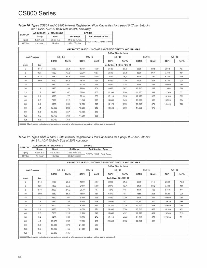
Table 70. Types CS805 and CS806 Internal Registration Flow Capacities for 1 psig / 0.07 bar Setpoint for 1-1/2 in. / DN 40 Body Size at 20% Accuracy
SETPOINTACCURACY: + / - 20% GAUGE SPRING
Droop Boost Set Range Part Number / Color1 psig -5.5 in. w.c. 5.5 in. w.c. 14 to 30 in. w.c.
GE30341X012 / Dark Green0.07 bar -14 mbar 14 mbar 35 to 75 mbar
CAPACITIES IN SCFH / Nm3/h OF 0.6 SPECIFIC GRAVITY NATURAL GAS
Inlet Pressure
Orifice Size, In. / mm
3/8 / 9.5 1/2 / 13 5/8 / 16 3/4 / 19 7/8 / 22
SCFH Nm3/h SCFH Nm3/h SCFH Nm3/h SCFH Nm3/h SCFH Nm3/h
psig bar Body Size: 1-1/2 in. / DN 40
2 0.14 1120 30.1 1710 45.9 2130 57.2 2600 69.8 2910 78.1
3 0.21 1620 43.5 2320 62.3 2510 67.4 3590 96.4 3750 101
5 0.34 2250 60.4 3090 83.0 3650 98,0 5190 139 5230 140
10 0.69 3150 84.6 4610 124 6320 170 7720 207 8330 224
15 1.0 3990 107 6310 169 8480 228 9390 252 10,000 269
20 1.4 4970 133 7600 204 9950 267 10,710 288 11,480 308
25 1.7 5490 147 8860 238 11,100 298 11,880 319 12,340 331
30 2.1 6590 177 9910 266 12,110 325 12,120 325 13,160 353
40 2.8 7890 212 11,640 313 13,000 349 13,590 365 13,920 374
50 3.4 9350 251 12,680 340 14,120 379 13,940 374 14,440 388
60 4.1 10,860 292 13,000 349 14,540 390 14,080 378
80 5.5 13,310 357 13,780 370
100 6.9 13,750 369 14,360 386
125 8.6 13,750 369
Blank areas indicate where maximum operating inlet pressure for a given orifice size is exceeded.
Table 71. Types CS805 and CS806 Internal Registration Flow Capacities for 1 psig / 0.07 bar Setpoint for 2 in. / DN 50 Body Size at 20% Accuracy
SETPOINTACCURACY: + / - 20% GAUGE SPRING
Droop Boost Set Range Part Number / Color1 psig -5.5 in. w.c. 5.5 in. w.c. 14 to 30 in. w.c.
GE30341X012 / Dark Green0.07 bar -14 mbar 14 mbar 35 to 75 mbar
CAPACITIES IN SCFH / Nm3/h OF 0.6 SPECIFIC GRAVITY NATURAL GAS
Inlet Pressure
Orifice Size, In. / mm
3/8 / 9.5 1/2 / 13 5/8 / 16 3/4 / 19 7/8 / 22
SCFH Nm3/h SCFH Nm3/h SCFH Nm3/h SCFH Nm3/h SCFH Nm3/h
psig bar Body Size: 2 in. / DN 50
2 0.14 1100 29.5 1590 42.7 2290 61.5 2670 71.7 2630 70.6
3 0.21 1390 37.3 2160 58.0 2970 79.7 3470 93.2 3730 100
5 0.34 2020 54.2 2970 79.7 4270 115 4770 128 5350 144
10 0.69 3230 86.7 4880 131 6870 184 7550 203 8520 229
15 1.0 3990 107 6190 166 8530 229 9470 254 10,990 295
20 1.4 4930 132 7380 198 10,690 287 11,190 300 13,620 366
25 1.7 5650 152 9190 247 12,240 329 12,630 339 14,680 394
30 2.1 6380 171 10,090 271 13,990 376 15,010 403 16,100 432
40 2.8 7830 210 12,900 346 16,080 432 18,220 489 19,340 519
50 3.4 9430 253 15,050 404 18,110 486 21,310 572 22,030 591
60 4.1 10,870 292 17,330 465 21,540 578 22,540 605
80 5.5 13,820 371 21,480 577
100 6.9 16,960 455 24,650 662
125 8.6 20,290 545
Blank areas indicate where maximum operating inlet pressure for a given orifice size is exceeded.
56
CS800 Series

Table 72. Types CS825 and CS826 Internal Registration Flow Capacities for 2 psig / 0.14 bar Setpoint at 1% ABS Accuracy
SETPOINTACCURACY: + / - 1% ABS SPRING
Droop Boost Set Range Part Number / Color2 psig -0.17 psig 0.17 psig 1 to 2.5 psig
GE30342X012 / Dark Blue0.14 bar -12 mbar 12 mbar 0.07 to 0.17 bar
CAPACITIES IN SCFH / Nm3/h OF 0.6 SPECIFIC GRAVITY NATURAL GAS
Inlet Pressure
Orifice Size, In. / mm
3/8 / 9.5 1/2 / 13 5/8 / 16 3/4 / 19 7/8 / 22
SCFH Nm3/h SCFH Nm3/h SCFH Nm3/h SCFH Nm3/h SCFH Nm3/h
psig bar Body Size: 1-1/2 in. / DN 40
3 0.21 690 19.8 1490 42.3 1070 30.5 1440 40.9 1660 47.2
5 0.34 860 24.4 1490 42.3 1840 52.4 2190 62.2 2490 70.5
10 0.69 1880 53.4 2560 72.7 3140 89.1 3980 113 4770 135
15 1.0 2510 71.2 3650 103 4280 121 5810 165 6300 179
20 1.4 3140 89.2 4710 134 5960 169 7950 225 8030 228
25 1.7 3920 111 5730 162 7210 204 8490 241 8880 252
30 2.1 4450 126 6890 195 7970 226 9260 262 10,420 295
40 2.8 6250 177 9020 256 10,170 288 11,090 314 11,770 333
50 3.4 7710 218 10,800 306 12,150 344 12,880 365 13,750 390
60 4.1 9580 271 11,390 323 13,100 371 13,210 374
80 5.5 11,570 328 13,200 374
100 6.9 12,990 368 14,020 397
125 8.6 13,320 377
psig bar Body Size: 2 in. / DN 50
3 0.21 720 20.5 930 26.4 1120 31.8 1410 40.1 1670 47.3
5 0.34 1100 31.1 1530 43.5 1860 52.8 2350 66.8 2720 77.1
10 0.69 1840 52.1 2260 64.1 3590 102 4430 126 5670 161
15 1.0 2560 72.6 3760 107 5520 157 7120 202 8710 247
20 1.4 3290 93.2 4930 140 7500 212 9730 276 11,600 329
25 1.7 4060 115 6520 185 10,010 284 12,580 356 14,370 407
30 2.1 4680 133 8120 230 11,840 335 14,820 420 17,200 487
40 2.8 6730 191 11,580 328 16,140 457 19,140 542 21,940 621
50 3.4 8800 249 14,080 399 19,900 564 23,390 663 26,300 745
60 4.1 10,580 300 16,950 480 24,370 690 26,970 764
80 5.5 13,590 385 22,090 626
100 6.9 16,680 472 27,290 773
125 8.6 20,280 574
Blank areas indicate where maximum operating inlet pressure for a given orifice size is exceeded.
57
CS800 Series

Table 73. Types CS825 and CS826 Internal Registration Flow Capacities for 2 psig / 0.14 bar Setpoint at 10% Accuracy
SETPOINTACCURACY: + / - 10% GAUGE SPRING
Droop Boost Set Range Part Number / Color
2 psig -0.20 psig 0.20 psig 1 to 2.5 psigGE30342X012 / Dark Blue
0.14 bar -14 mbar 14 mbar 0.07 to 0.17 bar
CAPACITIES IN SCFH / Nm3/h OF 0.6 SPECIFIC GRAVITY NATURAL GAS
Inlet Pressure
Orifice Size, In. / mm
3/8 / 9.5 1/2 / 13 5/8 / 16 3/4 / 19 7/8 / 22
SCFH Nm3/h SCFH Nm3/h SCFH Nm3/h SCFH Nm3/h SCFH Nm3/h
psig bar Body Size: 1-1/2 in. / DN 40
3 0.21 740 19.9 1580 42.4 1230 33.0 1620 43.5 1860 49.9
5 0.34 990 26.6 1720 46.2 2020 54.2 2730 73.3 2870 77.0
10 0.69 2040 54.8 2970 79.7 3490 93.7 4820 129 5290 142
15 1.0 2890 77.6 4170 112 5000 134 6510 175 7010 188
20 1.4 3600 96.6 5350 144 6580 177 8620 231 8690 233
25 1.7 4370 117 6430 173 7950 213 9240 248 9530 256
30 2.1 4960 133 7690 206 9030 242 10,240 275 11,060 297
40 2.8 6800 183 9790 263 11,040 296 11,890 319 12,590 338
50 3.4 8140 219 11,460 308 12,760 343 13,290 357 14,450 388
60 4.1 9850 264 12,100 325 13,760 369 14,020 376
80 5.5 12,110 325 13,830 371
100 6.9 13,720 368 14,800 397
125 8.6 13,880 373
psig bar Body Size: 2 in. / DN 50
3 0.21 810 21.7 1080 29.0 1340 36.0 1560 41.9 1780 47.8
5 0.34 1240 33.3 1760 47.2 2170 58.3 2750 73.8 3170 85.1
10 0.69 2100 56.4 2670 71.7 4130 111 4910 132 6300 169
15 1.0 2900 77.9 4220 113 6230 167 7920 213 9310 250
20 1.4 3640 97.7 5770 155 8400 226 10,470 281 12,460 335
25 1.7 4530 122 7180 193 10,660 286 13,300 357 14,970 402
30 2.1 5190 139 8840 237 12,270 330 15,280 410 17,900 481
40 2.8 7140 192 12,040 323 16,610 446 19,630 527 22,700 609
50 3.4 9020 242 14,530 390 20,410 548 23,830 640 26,840 721
60 4.1 10,720 288 17,070 458 24,980 671 27,450 737
80 5.5 13,660 367 22,220 597
100 6.9 16,760 450 27,350 734
125 8.6 20,350 546
Blank areas indicate where maximum operating inlet pressure for a given orifice size is exceeded.
58
CS800 Series

Table 74. Types CS825 and CS826 Internal Registration Flow Capacities for 2 psig / 0.14 bar Setpoint at 20% Accuracy
SETPOINTACCURACY: + / - 20% GAUGE SPRING
Droop Boost Set Range Part Number / Color2 psig -0.40 psig 0.40 psig 1 to 2.5 psig
GE30342X012 / Dark Blue0.14 bar -28 mbar 28 mbar 0.07 to 0.17 bar
CAPACITIES IN SCFH / Nm3/h OF 0.6 SPECIFIC GRAVITY NATURAL GAS
Inlet Pressure
Orifice Size, In. / mm
3/8 / 9.5 1/2 / 13 5/8 / 16 3/4 / 19 7/8 / 22
SCFH Nm3/h SCFH Nm3/h SCFH Nm3/h SCFH Nm3/h SCFH Nm3/h
psig bar Body Size: 1-1/2 in. / DN 40
3 0.21 1170 31.4 2020 54.2 2150 57.7 2570 69.0 3110 83.5
5 0.34 1770 47.5 2540 68.2 3130 84.0 4100 110 4520 121
10 0.69 3080 82.7 4420 119 5370 144 6800 183 7330 197
15 1.0 3880 104 5600 150 7180 193 8730 234 9850 264
20 1.4 4830 130 6970 187 9130 245 10,390 279 11,410 306
25 1.7 5740 154 8500 228 10,630 285 12,150 326 12,640 339
30 2.1 6180 166 9670 260 11,650 313 13,330 358 14,210 382
40 2.8 7810 210 12,190 327 13,870 372 15,330 412 15,860 426
50 3.4 9250 248 13,800 371 15,660 420 16,330 438 17,440 468
60 4.1 10,570 284 14,780 397 16,310 438 17,480 469
80 5.5 13,170 354 16,800 451
100 6.9 15,740 423 18,200 489
125 8.6 17,430 468
psig bar Body Size: 2 in. / DN 50
3 0.21 1070 28.7 1470 39.5 2080 55.8 2540 68.2 2710 72.8
5 0.34 1760 47.2 2660 71.4 3420 91.8 4130 111 4660 125
10 0.69 2860 76.8 4260 114 5930 159 7190 193 8360 224
15 1.0 3880 104 5950 160 8200 220 9920 266 11,340 304
20 1.4 4740 127 7360 198 10,200 274 12,310 331 14,410 387
25 1.7 5590 150 8830 237 12,560 337 15,100 405 16,980 456
30 2.1 6310 169 10,150 273 14,290 384 17,140 460 19,320 519
40 2.8 7820 210 12,990 349 18,360 493 21,510 577 23,500 631
50 3.4 9370 252 15,320 411 22,350 600 25,450 683 28,260 759
60 4.1 10,860 292 17,710 475 26,420 709 29,670 797
80 5.5 13,750 369 22,830 613
100 6.9 16,800 451 27,610 741
125 8.6 20,510 551
Blank areas indicate where maximum operating inlet pressure for a given orifice size is exceeded.
59
CS800 Series

CAPACITIES IN SCFH / Nm3/h OF 0.6 SPECIFIC GRAVITY NATURAL GAS
Inlet Pressure
Orifice Size, In. / mm
3/8 / 9.5 1/2 / 13 5/8 / 16 3/4 / 19 7/8 / 22
SCFH Nm3/h SCFH Nm3/h SCFH Nm3/h SCFH Nm3/h SCFH Nm3/h
psig bar Body Size: 1-1/2 in. / DN 40
10 0.69 770 21.9 1030 29.2 1370 39.0 1790 50.8 2010 57.0
15 1.0 1190 33.9 1720 48.9 2140 60.8 2560 72.5 2560 72.5
20 1.4 1500 42.6 1940 55.1 2710 77.0 3100 88.0 3500 99.3
25 1.7 1680 47.6 2350 66.6 3340 94.8 3920 111 4400 125
30 2.1 2160 61.4 2740 77.8 3840 109 4910 139 5040 143
40 2.8 2680 76.0 3860 109 4830 137 6520 185 6560 186
50 3.4 3420 96.9 4650 132 6040 171 7580 215 7980 226
60 4.1 4050 115 5780 164 7400 210 8950 254
80 5.5 5210 148 7660 217
100 6.9 6810 193 8940 253
125 8.6 7410 210
psig bar Body Size: 2 in. / DN 50
10 0.69 920 26.1 1220 34.7 1370 38.9 1730 49.0 1960 55.6
15 1.0 1300 37.1 1750 49.6 2020 57.5 2510 71.1 2930 83.0
20 1.4 1660 47.1 2180 61.7 2700 76.5 3220 91.3 3890 110
25 1.7 1930 54.8 2540 71.9 3140 89.1 4110 117 5490 155
30 2.1 2290 65.1 3060 86.8 3860 110 5270 149 6930 196
40 2.8 2870 81.5 4000 113 5370 152 8050 228 10,840 307
50 3.4 3510 99.6 5460 155 7860 223 10,990 311 14,620 414
60 4.1 4160 118 7250 205 11,130 315 15,400 436
80 5.5 6360 180 11,380 322
100 6.9 9640 273 16,370 464
125 8.6 13,250 375
Blank areas indicate where maximum operating inlet pressure for a given orifice size is exceeded.
Table 75. Types CS825 and CS826 Internal Registration Flow Capacities for 5 psig / 0.34 bar Setpoint at 1% ABS Accuracy
SETPOINTACCURACY: + / - 1% ABS SPRING
Droop Boost Set Range Part Number / Color5 psig -0.20 psig 0.20 psig 2.5 to 5.5 psig
GE30343X012 / Yellow0.34 bar -14 mbar 14 mbar 0.17 to 0.38 bar
60
CS800 Series

Table 76. Types CS825 and CS826 Internal Registration Flow Capacities for 5 psig / 0.34 bar Setpoint at 10% Accuracy
SETPOINTACCURACY: + / - 10% GAUGE SPRING
Droop Boost Set Range Part Number / Color5 psig -0.50 psig 0.50 psig 2.5 to 5.5 psig
GE30343X012 / Yellow0.34 bar -34 mbar 34 mbar 0.17 to 0.38 bar
CAPACITIES IN SCFH / Nm3/h OF 0.6 SPECIFIC GRAVITY NATURAL GAS
Inlet PressureOrifice Size, In. / mm
3/8 / 9.5 1/2 / 13 5/8 / 16 3/4 / 19 7/8 / 22SCFH Nm3/h SCFH Nm3/h SCFH Nm3/h SCFH Nm3/h SCFH Nm3/h
psig bar Body Size: 1-1/2 in. / DN 4010 0.69 1750 47.0 2360 63.4 2860 76.8 3630 97.4 4290 11515 1.0 2400 64.4 3530 94.8 4370 117 5400 145 5960 16020 1.4 3110 83.5 4270 115 5660 152 6630 178 7540 20225 1.7 3640 97.7 5320 143 6910 186 7870 211 8920 24030 2.1 4350 117 6240 168 7950 213 9530 256 10,490 28240 2.8 5490 147 7730 208 9760 262 11,740 315 12,770 34350 3.4 6850 184 9270 249 11,900 320 13,230 355 14,360 38660 4.1 7970 214 11,280 303 13,470 362 15,070 40580 5.5 10,650 286 13,750 369100 6.9 12,440 334 15,460 415125 8.6 14,500 389psig bar Body Size: 2 in. / DN 5010 0.69 1730 46.4 2400 64.4 2840 76.2 3620 97.2 4060 10915 1.0 2500 67.1 3410 91.5 4300 115 5360 144 6490 17420 1.4 3230 86.7 4360 117 5610 151 6950 187 8760 23525 1.7 3810 102 5280 142 6860 184 8960 241 11,030 29630 2.1 4410 118 6340 170 8430 226 10,780 289 13,080 35140 2.8 5550 149 8640 232 11,810 317 15,280 410 17,290 46450 3.4 6980 187 11,120 299 15,070 405 19,630 527 21,680 58260 4.1 8750 235 13,630 366 18,300 491 23,260 62480 5.5 11,970 321 18,590 499100 6.9 15,030 404 23,560 633125 8.6 19,350 520
Blank areas indicate where maximum operating inlet pressure for a given orifice size is exceeded.
Table 77. Types CS825 and CS826 Internal Registration Flow Capacities for 5 psig / 0.34 bar Setpoint at 20% Accuracy
SETPOINTACCURACY: + / - 20% GAUGE SPRING
Droop Boost Set Range Part Number / Color5 psig -1.0 psig 1.0 psig 2.5 to 5.5 psig
GE30343X012 / Yellow0.34 bar -69 mbar 69 mbar 0.17 to 0.38 bar
CAPACITIES IN SCFH / Nm3/h OF 0.6 SPECIFIC GRAVITY NATURAL GAS
Inlet PressureOrifice Size, In. / mm
3/8 / 9.5 1/2 / 13 5/8 / 16 3/4 / 19 7/8 / 22SCFH Nm3/h SCFH Nm3/h SCFH Nm3/h SCFH Nm3/h SCFH Nm3/h
psig bar Body Size: 1-1/2 in. / DN 4010 0.69 2460 66.0 3650 98.0 4680 126 5880 158 6610 17715 1.0 3460 92.9 5200 140 6520 175 8240 221 9120 24520 1.4 4370 117 6650 179 8300 223 10,120 272 11,110 29825 1.7 5220 140 7700 207 10,020 269 12,050 324 13,400 36030 2.1 6060 163 8980 241 11,440 307 13,520 363 15,180 40840 2.8 7580 204 11,060 297 14,160 380 16,400 440 17,610 47350 3.4 9150 246 12,850 345 16,250 436 17,880 480 19,590 52660 4.1 10,490 282 15,370 413 18,130 487 20,170 54280 5.5 13,270 356 18,410 494100 6.9 15,310 411 20,820 559125 8.6 18,730 503psig bar Body Size: 2 in. / DN 5010 0.69 2440 65.5 3650 98.0 4660 125 5740 154 6660 17915 1.0 3540 95.0 5220 140 6790 182 8260 222 9740 26220 1.4 4480 120 6650 179 8720 234 10,670 286 12,370 33225 1.7 5260 141 7950 213 10,580 284 13,090 351 15,060 40430 2.1 6100 164 9370 252 12,540 337 15,440 415 17,410 46740 2.8 7650 205 11,860 318 16,150 434 19,860 533 22,580 60650 3.4 9230 248 14,510 390 19,730 530 24,260 651 27,210 73160 4.1 10,710 288 16,820 452 23,710 637 28,650 76980 5.5 13,670 367 21,930 589100 6.9 16,630 446 27,000 725125 8.6 20,310 545
Blank areas indicate where maximum operating inlet pressure for a given orifice size is exceeded.
61
CS800 Series

D(STANDARD)
C
F
E
VENT
VENT
VENT VE
NT
BODY POSITION TO BE SPECIFIED BY THE PRIMARY REGULATOR
PRIMARY REGULATOR
TYPICAL TYPE CS800 VIEW
TYPICAL TYPE CS803 VIEW
VENT
VENT
VENT
VENT
VENT
VEN
TVE
NT
VENT
VENT
VENT VE
NT
D
D
C
C
F
F
E
E
BODY POSITION TO BE SPECIFIED BY THE PRIMARY REGULATOR
BODY POSITION TO BE SPECIFIED BY THE PRIMARY REGULATOR
PRIMARY REGULATOR
PRIMARY REGULATOR
SPRING BARREL FOR THE TYPE TM600 MONITOR WILL BE ORIENTED IN THE SAME DIRECTION AS THE PRIMARY REGULATOR SPRING BARREL
SPRING BARREL OF THE TYPE VSX8 SLAM-SHUT DEVICE SHALL BE SAME DIRECTION AS THE PRIMARY REGULATOR SPRING BARREL
VENT POSITION OF TYPE TM600 MONITOR WILL BE ORIENTED IN THE SAME DIRECTION AS THE PRIMARY REGULATOR
VENT POSITION OF TYPE VSX8 SLAM-SHUT DEVICE SHALL BE THE SAME DIRECTION AS THE PRIMARY REGULATOR
Figure 21. Spring Case Vent and Body Orientation
TYPICAL TYPE CS804 VIEW
62
CS800 Series

Ø 12.99 / 330.0
12.34 / 313.4
2.32 / 59.0 2.28 /
58.0
A/2A/2
AA
17.14 / 435.4
10.65 / 270.4
3.05 / 77.5
6.12 / 155.4
10.30 / 261.6
2.28 / 58.0
SCREENED VENT 1 OR 2-1/2 NPT
3/4 NPT CONTROL LINEEXTERNAL REGULATOR ONLY
TYPE CS800 REGULATOR MAIN VALVE
ERSA00347
Figure 22. Dimensions
GG00886_A
POSITION 1(STANDARD)
POSITION 2 POSITION 3 POSITION 4
Figure 21. Spring Case Vent and Body Orientation (continued)
In. / mm
63
CS800 Series

Table 78. Dimensions
BODY SIZEEND CONNECTION STYLE
DIMENSION A
In. DN In. mm
1-1/4 to 2 - - - - NPT or Rp 6.12 155
2(1) 50(1) CL125 FF Flange7.5 10 191 254
2(2) 50(2) CL125 FF, CL150 FF or PN 10/16 Flange
2(2) 50(2) CL125 FF or CL150 FF Flange 10.5 267
2(3) 50(3) CL150 RF or PN 16 Flange 10 254
1. For Cast Iron.2. For Ductile Iron. 3. For Steel.
ERSA00347
Figure 22. Dimensions (continued)
TYPE CS850 REGULATOR MAIN VALVE
SCREENED VENT 1 OR 2-1/2 NPT
SLAM-SHUT MODULE TRUE-MONITOR™ MODULE
Ø 12.99 /330.0
12.34 /313.4
17.14 /435.4
SCREENED VENT 1/4 NPT
7.91 /201
5.77 /146.5
A/2
A
11.85 /301.1
5.95 /151.2
SCREENED VENT 1 NPT
A/2
A
10.65 /270.4
3.05 /77.5
6.12 /155.4
10.63 /270.0
14.17 /360.0
2.28 /58.0
+25 mm FOR RESET
In. / mm
64
CS800 Series

Ordering InformationWhen ordering, complete the ordering guide on thispage. Refer to the Specifications section on page 2. Review the description to the right of each
With Type Secondary Seat Protection with Vent CS806IR CS806IQ CS826IR CS826IQ With Slam Shut CS804IN CS804IT CS804IL CS804EN CS804ET CS804EL CS824IN CS824IT CS824IL CS824EN CS824ET CS824EL CS854IN CS854EN Body Material, Body Size and End Connection (Select One) Gray Cast Iron (Types CS800, CS805, CS806, CS820, CS825, CS826 and CS850)
1-1/4 NPT*** 1-1/2 NPT*** 2 NPT*** NPS 2 / DN 50, CL125 FF*** Face-to-face dimension: 7.5 in. / 191 mm 10 in. / 254 mm Gray Cast Iron (Types CS803, CS823, CS804, CS824 and CS854)
2 NPT***
specification and the information in each referenced table or figure. Specify your choice whenever a selection is offered.
Ordering GuideType (See Table 1 for Construction Features) (Select One) Stand-Alone Regulator CS800IN CS800IR CS800IT CS800IQ CS800IL CS800EN CS800ET CS800EL CS820IN CS820IR CS820IT CS820IQ CS820IL CS820EN CS820ET CS820EL CS850IN CS850EN With Integral True-Monitor™ Module CS803IN CS803IT CS803IL CS803EN CS803ET CS803EL CS823IN CS823IT CS823IL CS823EN CS823ET CS823EL With Type Secondary Seat™ Protection Without Vent CS805IN CS805IR CS805IT CS805IQ CS825IN CS825IR CS825IT CS825IQ
65
CS800 Series
- continued -

1. 10 in. / 254 mm face-to-face dimension
Ductile Iron (Types CS800, CS803, CS820, CS823 and CS850)
1-1/4 NPT*** 1-1/2 NPT*** 2 NPT*** Rp 1-1/4*** Rp 1-1/2*** Rp 2*** NPS 2 / DN 50, CL125 FF / CL150 FF*** Face-to-face dimension: 7.5 in. / 191 mm 10 in. / 254 mm 10.5 in. / 267 mm NPS 2 / DN 50, PN 10/16*** Face-to-face dimension: 7.5 in. / 191 mm 10 in. / 254 mm
Ductile Iron (Types CS804, CS824 and CS854) 1-1/2 NPT*** 2 NPT*** Rp 2*** NPS 2 / DN 50, CL125 FF / CL150 FF*** Face-to-face dimension: 10 in. / 254 mm 10.5 in. / 267 mm NPS 2 / DN 50, PN 10/16***(1)
WCC Steel (Types CS800, CS803, CS820, CS823 and CS850)
1-1/4 NPT*** 1-1/2 NPT*** 2 NPT*** Rp 1-1/4*** Rp 1-1/2*** Rp 2*** NPS 2 / DN 50, CL150 RF***(1)
NPS 2 / DN 50, PN 10/16***(1)
WCC Steel (Types CS804, CS824 and CS854) 1-1/2 NPT*** 2 NPT*** Rp 2*** NPS 2 / DN 50, CL150 RF***(1)
NPS 2 / DN 50, PN 10/16***(1)
Outlet Pressure Range (See Table 4) (Select One) 3.5 to 6 in. w.c. / 9 to 15 mbar, Red 5.5 to 8.5 in. w.c. / 13 to 21 mbar, Black 5.5 to 8.5 in. w.c. / 13 to 21 mbar, Brown 8 to 12 in. w.c. / 20 to 30 mbar, Purple 10 to 16 in. w.c. / 25 to 40 mbar, White 14 to 30 in. w.c. / 35 to 75 mbar, Dark Green 1 to 2.5 psig / 69 to 170 mbar, Dark Blue 1.5 to 3.5 psig / 100 to 241 mbar, Orange 2.5 to 5.5 psig / 170 to 380 mbar, Yellow 5 to 10 psig / 345 to 690 mbar, Green with White StripeOrifice Size (Select One) Types CS800, CS804, CS820, CS824, CS850 and CS854 1/4 in. / 6.4 mm 3/8 in. / 9.5 mm 1/2 in. / 13 mm 5/8 in. / 16 mm 3/4 in. / 19 mm 7/8 in. / 22 mm 1 in. / 25 mm 1-3/8 in. / 34.9 mm Types CS803 and CS823 1/4 in. / 6.4 mm 3/8 in. / 9.5 mm 1/2 in. / 13 mm 5/8 in. / 16 mm 3/4 in. / 19 mm 7/8 in. / 22 mm 1 in. / 25 mm Types CS805, CS825, CS855, CS806, CS826 and CS856 3/8 in. / 9.5 mm 1/2 in. / 13 mm 5/8 in. / 16 mm 3/4 in. / 19 mm 7/8 in. / 22 mmBody Orientation (Select one, see Figure 21) Position 1 (standard)*** Position 2*** Position 3*** Position 4***
- continued -
Ordering Guide (continued)
66
CS800 Series

Vent Orientation (Select one, see Figure 21) Position C*** Position D (standard)*** Position E*** Position F***True-Monitor™ Control Pressure Range (For CS803 and CS823 Series) (See Tables 7 and 8, select one if applicable) 12 to 21 in. w.c. / 30 to 52 mbar, Blue 18 to 30 in. w.c. / 45 to 75 mbar, Green 26 to 40 in. w.c. / 65 to 99 mbar, Orange 1.4 to 2.9 psig / 97 to 200 mbar, Black 2.6 to 3.7 psig / 179 to 255 mbar, Purple 3.6 to 6 psig / 248 to 414 mbar, Dark Blue 5.1 to 7.5 psig / 352 to 517 mbar, RedSlam-Shut Trip Pressure Setting(For CS804, CS824 and CS854 Series)(Select one if applicable and specify setpoint/s, see Tables 12 and 13) Overpressure Protection Only (OPSO) Supply setpoint required____________________
Overpressure and Underpressure Protection (OPSO/UPSO) Supply overpressure setpoint required _______________________________________ Supply underpressure setpoint required _______________________________________
Ordering Guide (continued)Options (Select all that apply) Enhanced Low Inlet Pressure Flow Performance
Choose this option for enhanced flow performance for low inlet pressure systems, up to 25 psig / 1.7 bar. This option applies to the 5.5 to 8.5 in. w.c. / 13 to 21 mbar spring range when combined with 2 in. threaded or flanged bodies only.
Low Relief Start-to-Discharge (STD) SpringThis option provides a relief start-to-discharge range of 7 to 14 in. w.c. / 17 to 35 mbar above setpoint for the Type CS800IR or CS800IQ with a spring range of up to 10 to 16 in. w.c. / 25 to 40 mbar.
Closing Cap and Setpoint Seal Wire Stabilizer Cartridge
Regulators Quick Order Guide* * * Readily Available for Shipment
* * Allow Additional Time for Shipment
* Special Order, Constructed from Non-Stocked Parts. Consult your local Sales Office for Availability.
Availability of the product being ordered is determined by the component with the longest shipping time for the requested construction.
Specification WorksheetApplication:Specific UseLine SizeGas Type and Specific GravityGas TemperatureDoes the Application Require Overpressure Protection? Yes No If yes, which is preferred: Relief Valve Monitor Regulator Shutoff DeviceIs overpressure protection equipment selection assistance desired?Pressure:Maximum Inlet Pressure (P1max)Minimum Inlet Pressure (P1min)Downstream Pressure Setting(s) (P2)Maximum Flow (Qmax)Performance Required:Accuracy Requirements?Need for Extremely Fast Response?Other Requirements:
67
CS800 Series

CS800 Series
Facebook.com/EmersonAutomationSolutions
LinkedIn.com/company/emerson-automation-solutions
Twitter.com/emr_automation
The distinctive swirl pattern cast into every actuator casing uniquely identifies the regulator as part of the Fisher™ brand Commercial Service Regulator family and assures you of the highest-quality engineering, performance, and support traditionally associated with Fisher™ and Tartarini™ regulators. Visit www.fishercommercialservice.com to access interactive applications.
Fisher.com
Emerson Automation Solutions
Americas McKinney, Texas 75070 USA T +1 800 558 5853
+1 972 548 3574
Europe Bologna 40013, Italy T +39 051 419 0611
Asia Pacific Singapore 128461, Singapore T +65 6777 8211
Middle East and Africa Dubai, United Arab Emirates T +971 4 811 8100
D103140X012 © 2010, 2019 Emerson Process Management Regulator Technologies, Inc. All rights reserved. 07/19. The Emerson logo is a trademark and service mark of Emerson Electric Co. All other marks are the property of their prospective owners. Fisher™ is a mark owned by Fisher Controls International LLC, a business of Emerson Automation Solutions.
The contents of this publication are presented for informational purposes only, and while every effort has been made to ensure their accuracy, they are not to be construed as warranties or guarantees, express or implied, regarding the products or services described herein or their use or applicability. All sales are governed by our terms and conditions, which are available upon request. We reserve the right to modify or improve the designs or specifications of such products at any time without notice.
Emerson Process Management Regulator Technologies, Inc does not assume responsibility for the selection, use or maintenance of any product. Responsibility for proper selection, use and maintenance of any Emerson Process Management Regulator Technologies, Inc. product remains solely with the purchaser.