cs2353 - object oriented analysis and design
DESCRIPTION
ooad manualTRANSCRIPT

http:/
/csetu
be.co
.nr/
GKMCET
Lecture Plan
Subject code & Subject Name: CS2353 & OOAD
Unit Number: I
INTRODUCTION TO OOAD What is OOAD?
What is UML?
What is OOAD?
During OOA there is an emphasis on finding and describing the objects or
concepts in the problem.
(Ex) In the case of the flight information system, some of the concepts
include plane, flight and pilot.
During OOD there is an emphasis on defining software objects and how they collaborate
to fulfill the requirements.
(Ex) a plane software object may have a tail number attribute and a get
flight history method.
What is UML?
UML is a language for specifying, constructing, visualizing and documenting the
software system and its components. The UML is a graphical language with sets of rules
and semantics, the rules and semantics of a model are expressed in English.
Three ways to apply UML
Three perspectives to apply UML
The meaning of class in different perspectives
http://csetube.co.nr/

http:/
/csetu
be.co
.nr/
GKMCET
Lecture Plan
Subject code & Subject Name: CS2353 & OOAD
Three ways to apply UML
UML as sketch
UML as blueprint
UML as programming language
UML as sketch
Informal and incomplete diagrams created to explore difficult parts of the
problem or solution space, exploiting the power of visual languages.
UML as blueprint
Relatively detailed design diagrams used either for
(1) Reverse engg to visualize and better understanding existing code in UML
diagrams.
(Or)
(2) Code generation (forward engg)
If reverse engg, a UML tool reads the source and generates UML
packages, class and sequence diagrams. These blueprints can help the
reader understand the big picture elements, structure and collaborations.
Before programming, some detailed diagrams can provide guidance for
code generation, either manually or automatically with a tool.
UML as programming language
Complete executable specification of a software system in UML, executable code
will be automatically generated but is not seen or modified by developers.
http://csetube.co.nr/

http:/
/csetu
be.co
.nr/
GKMCET
Lecture Plan
Subject code & Subject Name: CS2353 & OOAD
Three perspectives to apply UML
Conceptual perspective
Specification (software) perspective
Implementation (software) perspective
Conceptual perspective
The diagrams are interpreted as describing things in a situation of the real world
or domain of interest.
Specification (software) perspective
The diagrams describe software abstractions or components with specifications
and interfaces, but no commitment to a particular implementation.
Implementation (software) perspective
The diagrams describe software implementations in a particular technology.
The meaning of class in different perspectives
In UML, a class is drawn as rectangular boxes are called classes.
Conceptual class- real world concept or thing. A conceptual or essential
perspective.
Software class- a class representing a specification or implementation
perspective of a software component, regardless of the process or method.
Implementation class – a class implemented in a specific OO language
such as java.
http://csetube.co.nr/

http:/
/csetu
be.co
.nr/
GKMCET
Lecture Plan
Subject code & Subject Name: CS2353 & OOAD
What are the unified process phases?
Inception
Elaboration
Construction
Transition
Inception
Approximate vision, business case, scope, vague estimates.
Elaboration
Refined vision, iterative implementation of the core architecture, resolution of
high risks, identification of most requirements and scope, more realistic estimates.
Construction
Iterative implementation of the remaining lower risk and easier elements, and
preparation for deployment.
Transition
Beta tests, deployment.
Inception is not a requirements phase, rather, it is a feasibility phase, where just enough
investigation is done to support a decision to continue or stop.
Similarly, elaboration is not the requirements or design phase, rather, it is a phase where
the core architecture is iteratively implemented, and high risk issues are mitigated.
Inception
It is the initial step to establish a common vision and basic scope for the project. It
will include analysis of perhaps 10% of the use cases, analysis of the critical non-
functional requirement environment so that programming can start in the following
elaboration phase.
http://csetube.co.nr/
http:/
/csetu
be.co
.nr/
GKMCET
Lecture Plan
Subject code & Subject Name: CS2353 & OOAD
Inception artifacts
Vision and business case
Use-case model
Supplementary specification
Glossary
Risk list and risk management plan
Prototypes and proof of concepts
Iteration plan
Phase plan and software development plan
Development case
These artifacts are only partially completed in this phase. They will be iteratively refined
in subsequent iterations. Name capitalization implies an officially named UP artifact.
CASE STUDY – the NextGen POS system
In this apparently straightforward problem domain, we shall see that there are
interesting requirement and design problems to solve. In addition, it’s a real problem-
groups really do develop POS systems with object technologies.
Use case modeling
The UP defines the use case model within the requirements discipline.
Primarily, this is the set of all written use cases; it is a model of the
systems functionality and environment.
Use cases are text documents, not diagrams, and use case modeling is
primarily an act of writing text, not drawing diagrams.
http://csetube.co.nr/
http:/
/csetu
be.co
.nr/
GKMCET
Lecture Plan
Subject code & Subject Name: CS2353 & OOAD
The use case model is not only requirement artifact in the UP. There are
also the supplementary Specification, Glossary, Vision, and Business
Rules. These are all useful for requirements analysis, but secondary at this
point.
The use case model may optionally include a UML use case diagram to
show the names of the use cases and actors, and their relationships. It also
provides a quick way to list the use cases by name.
Relating use cases
Include
Extend
Generalization
Include relationship
Use includes when you are repeating yourself in two or more separate use cases
and you want to avoid repetition.
Another motivation is simply to decompose the long use case into subunits to
improve comprehension.
Another use of the include relationship is to describe the handling of an
asynchronous event, such as when a user is able to, at any time, select or branch to a
particular window, function or within a range of steps.
Extend relationship
The extend relationship is used when we have one use case that is similar to
another use case but does a bit more. In essence, it is like a subclass.
http://csetube.co.nr/
http:/
/csetu
be.co
.nr/
GKMCET
Lecture Plan
Subject code & Subject Name: CS2353 & OOAD
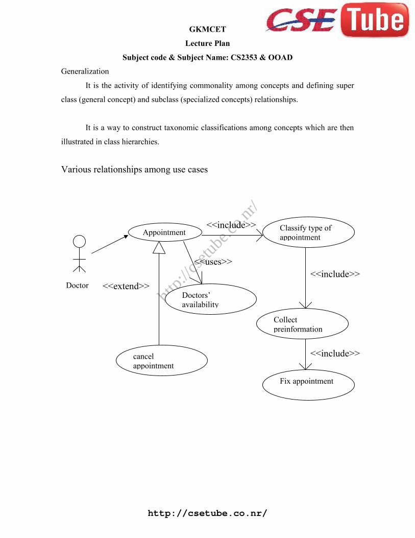
Generalization
It is the activity of identifying commonality among concepts and defining super
class (general concept) and subclass (specialized concepts) relationships.
It is a way to construct taxonomic classifications among concepts which are then
illustrated in class hierarchies.
Various relationships among use cases
Appointment Classify type ofappointment
Collectpreinformation
Fix appointment
Doctors’availability
cancelappointment
<<extend>>
<<include>>
<<include>>
<<include>>
<<uses>>
Doctor
http://csetube.co.nr/

http:/
/csetu
be.co
.nr/
GKMCET
Lecture Plan
Subject code & Subject Name: CS2353 & OOAD
Generalization
Lecture Plan
Subject code & Subject Name: CS2353 & OOAD Issue: C Rev: 00
Validate user
Check password Voice recognition
Patient
In-Patient Out-Patient
http://csetube.co.nr/

http:/
/csetu
be.co
.nr/
GKMCET
Lecture Plan
Subject code & Subject Name: CS2353 & OOAD
Unit Number: II
ElaborationElaboration is the initial series of interactions during which, on a normal
project:
The core, risky software architecture is programmed and tested
The majority of requirements are discovered and stabilized
The major risks are mitigated or retired
Elaboration is the initial series of iterations during which the team does serious
investigation, implements (program and tests) the core architecture, clarifies most
requirements, and tackles the high-risk issues.
Elaboration often consists of two or more iterations; each iteration is
recommended to be between two and six weeks, prefer the shorter versions unless the
team size is massive. Each iteration is time boxed, meaning its end date is fixed.
Elaboration is not a design phase or a phase when the models are fully
developed in preparation for implementation in the construction step- that would be an
example of superimposing waterfall ideas on iterative development and the UP.
Some key ideas and best practices will manifest in elaboration:
Do short time boxed risk-driven iterations
Start programming early
Adaptively design, implement, and test the core and risky parts
of the architecture
Test early, often, realistically
Adapt based on feedback from tests, users, developers
Write most of the use cases and other requirements in detail,
through a series workshops, once per elaboration iteration
http://csetube.co.nr/

http:/
/csetu
be.co
.nr/
GKMCET
Lecture Plan
Subject code & Subject Name: CS2353 & OOADUnit Number: II Period: 10 Page: 2 of 2
What artifacts may start in elaboration?Sample elaboration artifacts, excluding those started in inception.
You know You Didn’t Elaboration When… It is more than “a few” months long for most projects.
It only has one iteration
Most requirements were defined before elaboration
The risky elements and core architecture are not being tackled
There is no early and realistic testing.
The architecture is speculatively finalized before programming
Artifact Comment
Domain model This is visualization of the domain concepts; it is similar to a
static information model of the domain entities.
Design model This is the set of diagrams that describes the logical design.
This includes software class diagrams, object interaction
diagrams, Package diagrams and so forth.
Software
Architecture
Document
A learning aid that summarizes the key architectural issues
and their resolution in the design. It is a summary of the
Outstanding design ideas and their motivation in the system.
Data model This includes the database schemas, and the mapping strategies
between object and Non-object representations.
Use-case
storyboards,
UI prototypes
A description of the user interface, paths of navigation,
usability
models and so forth.
http://csetube.co.nr/

http:/
/csetu
be.co
.nr/
GKMCET
Lecture Plan
Subject code & Subject Name: CS2353 & OOADUnit Number: II Period: 10 Page: 2 of 2
It does not result in an executable architecture; there is no production- code
programming.
There is minimal feedback and adaptation; users are not continually engaged in
evaluation and feedback.
It is considered a step to do the proof-of-concept programming, rather than
programming the production core executable architecture.
If a project exhibits these symptoms, the elaboration phase was not understood, and
waterfall- thinking has been superimposed on the UP.
Domain models What is a domain model?
Motivation: why create a domain model?
Guideline: how to create a domain model?
What is a domain model?
A domain model is a visual representation of conceptual classes or real-situation
objects in a domain. Domain models have also been called conceptual models, domain
object models and analysis object models.
In the UP “Domain Model” means a representation of real-situation conceptual
classes, not of software objects. The term does not mean a set of diagrams describing
software classes, the domain layer of a software architecture or software objects with
responsibilities. Applying UML notation, a domain model is illustrated with a set of
class diagrams in which no operations (method signature) are defined. It provides a
conceptual perspective. It may show:
Domain objects or conceptual classes
Associations between conceptual classes
Attributes of conceptual classes
Definition: why call a domain model a “visual dictionary”?
See Fig 9.2-Partial domain model- a visual dictionary in Pg.No-133.
http://csetube.co.nr/
http:/
/csetu
be.co
.nr/
GKMCET
Lecture Plan
Subject code & Subject Name: CS2353 & OOAD
The information it illustrates (using UML notation) could alternatively have been
expressed in plain text (in the UP glossary). But it’s easy to understand the terms and
especially their relationships in a visual language, since our brains are good at
understanding visual elements and line connection.
The domain model is a visual dictionary of the noteworthy abstractions, domain
vocabulary, and information content of the domain.
Definition: is a domain model picture of software business objects?
The following elements are not suitable in a domain model:
Software artifacts, such as a window or a database, unless the
domain being modeled are of software concepts, such as a model
of graphical user interfaces.
Responsibilities or methods.
Definition: what are 2-traditional meanings of “domain model”?
Domain model is conceptual perspective of objects in a real situation of the
world, not a software perspective. But the term is overloaded; it also has been used to
mean “the domain layer of software objects”.
That is, the layer of software objects below the presentation or UI layer that is
composed of domain objects- software objects that represent things in the problem
domain space with related “business logic” or “domain logic” methods.
For example, a board software class with a getSquare method.
Definition: what are conceptual classes?
A conceptual class is an idea, thing, or object. More formally, a conceptual class
may be considered in terms of its symbol, intension, and extension (see Fig-9.5).
Symbol – words or images representing a conceptual class
Intension – the definition of a conceptual class
http://csetube.co.nr/

http:/
/csetu
be.co
.nr/
GKMCET
Lecture Plan
Subject code & Subject Name: CS2353 & OOAD
Extension – the set of examples to which the conceptual class
applies.
Definition: are domain and data model the same thing?
A domain model is not a data model, so do not exclude a class simply because the
requirements don’t indicate any obvious need to remember information about it or
because the conceptual class has no attributes.
Motivation: why create a domain model?
Motivation: lower representational gap with OO modeling
This is a key idea in OO: use software class names in the domain layer inspired
from names in the domain model, with objects having domain-familiar information and
responsibilities. Fig-9.6 illustrates the idea. This supports a low representational gap
between our mental and software models. And that’s not just a philosophical nicety- it
has a practical time and money impact. For example, a source code payroll program
written in 1953:
100001010100011110101011011010001010101010101111010101….
As compute science people, we know it runs, but the gap between this software
representation and our mental model of the payroll domain is huge, that profoundly
affects comprehension (and modification) of the software. OO modeling can lower that
gap.
Guideline: how to create a domain model
Bounded by the current iteration requirements under design:
1. Find the conceptual classes
2. Draw them as classes in a UML class diagram.
3. Add associations and attributes.
http://csetube.co.nr/

http:/
/csetu
be.co
.nr/
GKMCET
Lecture Plan
Subject code & Subject Name: CS2353 & OOAD
Finding conceptual classes and description classes
Finding conceptual classes Guideline: how to find conceptual classes?
3-strategies to find conceptual classes
1. Reuse or modify existing models. This is the first, best, and usually easiest
approach.
2. Use a category list (see table 9.1)
3. Identify noun phrases.
Reusing existing models is excellent, but outside our scope. The second method, using
a category list, is also useful.
Guideline: when to model with description classes?
A description class contains information that describes something else. For
example, a ProductDescription that records the price, picture, and text description of an
Item. This was first named the Item- Descriptor pattern.
Motivation: why use description classes?
Guideline: when are description classes useful?
AssociationsAn association is a relationship between classes that indicates some meaningful and
interesting connection. In the UML associations are defined as “the semantic
relationship between two or more classifiers that involve connections among their
instances”.
Guideline: when to show an association?
Guideline: why should we avoid adding many associations?
Perspectives: will the associations be implemented in software?
Applying UML: association notation
http://csetube.co.nr/

http:/
/csetu
be.co
.nr/
GKMCET
Lecture Plan
Subject code & Subject Name: CS2353 & OOAD
Guideline: how to name an association in UML?
Applying UML: roles
Applying UML: multiplicity
Applying UML: multiple associations between two classes
Guideline: how to find associations with a common association list
AttributesIt is useful to identify those attributes of conceptual classes that are needed to
satisfy the information requirements of the current scenarios under development. An
attribute is a logical data value of an object.
Guideline: when to show attributes?
Applying UML: attribute notation
More Notations
Guideline: where to record attribute requirements?
Derived attributes
Guideline: what are suitable attribute types?
Focus on data type attributes in the domain model
Data types
Perspectives: what about attribute in code?
Guideline: when to define new data type classes?
Applying UML: where to illustrating these data type classes?
Guideline: no attributes representing foreign keys
Guideline: modeling quantities and units
http://csetube.co.nr/

http:/
/csetu
be.co
.nr/
GKMCET
Lecture Plan
Subject code & Subject Name: CS2353 & OOAD
Domain model refinement
New concepts for the NextGen domain model
Noun phrase identification from the use cases
Authorization service transactions
Generalization
Defining conceptual super classes and sub classes
Generalization and conceptual class definition
Generalization and class sets
Conceptual subclass definition conformance
Conceptual sub class set conformance
What is a correct conceptual sub class?
When to define a conceptual subclass?
Motivations to partition a conceptual class into sub classes
When to define conceptual super class?
Finding conceptual class hierarchiesConceptual Classes
Informally, a conceptual class is an idea, thing, or object. More formally, a conceptual
class may be considered in terms of its symbol, intension, and extension
Symbol - words or images representing a conceptual class.
Intension - the definition of a conceptual class.
Extension - the set of examples to which the conceptual class applies.
http://csetube.co.nr/

http:/
/csetu
be.co
.nr/
GKMCET
Lecture Plan
Subject code & Subject Name: CS2353 & OOAD
For example, consider the conceptual class for the event of a purchase transaction. We
may choose to name it by the symbol Sale. The intension of a Sale may state that it
"represents the event of a purchase transaction, and has a date and time." The extension
of Sale is all the examples of sales; in other words, the set of all sales
Payment classes
Authorization service classes
Authorization transaction classes
Aggregation and composition
Both aggregation and composition are special kinds of associations. Aggregation
is used to represent ownership or a whole/part relationship, and composition is used to
represent an even stronger form of ownership. With composition, we get coincident
lifetime of part with the whole. The composite object has sole responsibility for the
disposition of its parts in terms of creation and destruction. In implementation terms, the
composite is responsible for memory allocation and deallocation.
Moreover, the multiplicity of the aggregate end may not exceed one; i.e., it is
unshared. An object may be part of only one composite at a time. If the composite is
destroyed, it must either destroy all its parts or else give responsibility for them to some
other object. A composite object can be designed with the knowledge that no other object
will destroy its parts.
Composition can be used to model by-value aggregation, which is semantically
equivalent to an attribute. In fact, composition was originally called aggregation-by-value
http://csetube.co.nr/

http:/
/csetu
be.co
.nr/
GKMCET
Lecture Plan
Subject code & Subject Name: CS2353 & OOAD
in an earlier UML draft, with “normal” aggregation being thought of as aggregation-by-
reference. The definitions have changed slightly, but the general ideas still apply. The
distinction between aggregation and composition is more of a design concept and is not
usually relevant during analysis.
Finally, a word of warning on terminology. While UML uses the terms association,
aggregation, and composition with specific meanings, some object-oriented authors use
one or more of these terms with slightly different interpretations. For example, it is fairly
common to see all three UML relationships grouped under a single term, say
composition, and then to discuss object-oriented relationships as being either inheritance
(generalization) or composition.
How to identify composition
A benefit of showing composition
Composition in the NextGen domain model
UML activity diagrams and modeling How to apply activity diagrams?
Business process modeling
Data flow modeling
Concurrent programming and parallel algorithm modeling
More UML activity diagram notation
Guidelines
Example: NextGen activity diagram
Process: activity diagrams in the UP
Background
http://csetube.co.nr/

http:/
/csetu
be.co
.nr/
GKMCET
Lecture Plan
Subject code & Subject Name: CS2353 & OOAD
UML Activity DiagramAn activity diagram is a variation or special case of a state machine, in which the
states are activities representing the performance of operations and the transitions are
triggered by the completion of the operations.
The purpose of an activity diagram is to provide a view of flows and what is
going on inside a use case or among several classes. (See fig 28.7 in Pg.No- 483)
An activity is shown as a round box, containing the name of the operation. When
an operation symbol appears within an activity diagram or other state diagram, it
indicates the execution of the operation.
The concurrent control is represented by multiple arrows leaving a
synchronization bar, which is represented by a short thick bar with incoming and
outgoing arrows.
An activity diagram is used mostly to show the internal state of an object, but
external events may appear in them. Activity and state diagrams express a decision when
conditions are used to indicate different possible transitions that depend on Boolean
conditions of container object.
Actions may be organized into swim lanes, each separated from neighboring
swim lanes by vertical solid lines on both sides. Each swim lane represents responsibility
for part of the overall activity and may be implemented by one or more objects.
http://csetube.co.nr/

http:/
/csetu
be.co
.nr/
GKMCET
Lecture Plan
Subject code & Subject Name: CS2353 & OOAD
Unit Number: III
System sequence diagrams (SSD)SSD is a fast and easily created artifact that illustrates input and output events
related to the systems under discussion. They are input to operation contracts and most
importantly object design. The UML contains notation in the form of sequence
diagrams to illustrate events from external actors to a system.
What are system sequence diagrams?
Motivation: why draw an SSD?
Applying UML: sequence diagrams
What is the relationship between SSDs and use cases?
How to name system events and operations?
How to model SSDs involving other external systems?
What SSD information to place in the glossary?
Process: iterative and evolutionary SSDs
What are system sequence diagrams?
Use cases describe how external actors interact with the software system we are
interested in creating. During this interaction an actor generates system events to a
system, usually requesting some system operation to handle the event. The UML
includes sequence diagrams as a notation that can illustrate actor interactions and the
operations initiated by them.
A system sequence diagrams is a picture that shows, for one particular scenario
of a use case, the events that external actors generate, their order and inter system
events. All systems are treated as a black box; the emphasis of the diagram is events
that cross the system boundary from actors to systems.
http://csetube.co.nr/

http:/
/csetu
be.co
.nr/
GKMCET
Lecture Plan
Subject code & Subject Name: CS2353 & OOAD
Motivation: why draw an SSD?
It is useful to know what, precisely, are the external input events the system
events. They are an important part of analyzing system behavior. System behavior is a
description of what a system does, without explaining how it does it. One part of that
description is a system sequence diagram. Other parts include the use cases and system
operation contracts.
We may be familiar with the idea of identifying the messages that go into one
software object. But this concept is useful at higher levels of components, including the
entire system viewed as one thing or object.
Applying UML: sequence diagrams
The UML does not define something called a “system” sequence diagrams but
simply a “sequence diagram”. The qualification is used to emphasize its application to
systems as black boxes. Later, sequence diagrams will be used in another context- to
illustrate the design of interacting software objects to fulfill work.
Loops in sequence diagrams (See figure 10.2 in page number- 175)
What is the relationship between SSDs and use cases?
An SSD shows system events for one scenario of a use case, therefore it is
generated from inspection of a use case (see figure 10.3)
How to name system events and operations?
System events should be expressed at the abstract level of intention rather than
in terms of the physical input device. It also improves clarity to start the name of a
system event with a verb (add…, enter…, end.., make…) see fig-10.4 in pg.no-178.
http://csetube.co.nr/

http:/
/csetu
be.co
.nr/
GKMCET
Lecture Plan
Subject code & Subject Name: CS2353 & OOAD
How to model SSDs involving other external systems?
SSDs can also be used to illustrate collaborations between systems. However,
this is deferred until a later iteration in the case study, since this iteration does not
include remote system collaboration.
What SSD information to place in the glossary?
The elements show in SSD (operation name, parameters, and return data) is
terse. These may need proper explanation so that during design it is clear what is
coming in and going out. The glossary is a great place for these details. (See fig-10.2 in
pg.no-175)
Process: iterative and evolutionary SSDs
Don’t create SSDs for all scenarios, unless you are using an estimation
technique (such as function point counting) that requires identification of all system
operations. Rather, draw them only for the scenarios chosen for the next iteration. And,
they shouldn’t take long to sketch- perhaps a few minutes or a half hour.
SSDs are only very useful when you want to understand the interface and
collaborations of exiting systems, or to document the architecture.
SSDs within UP
UP phases
Logical architecture and UML package diagramThe Logical architecture is the large-scale organization of the software classes
into packages (or namespaces), subsystems, and layers. It’s called the logical
architecture because there’s no decision about hoe these elements are deployed across
different operating system processes or across physical computers in a network (these
latter decision are part of the deployment architecture)
A layer is a very coarse-grained grouping of classes, packages, or subsystems that
has cohesive responsibility for a major of the system. Also layers are organized such
that “higher” layers call upon services of “lower” layers, but not normally vice versa.
Typically layers in an OO system include:
http://csetube.co.nr/

http:/
/csetu
be.co
.nr/
GKMCET
Lecture Plan
Subject code & Subject Name: CS2353 & OOAD
User interface
Application logic and domain objects
Technical services
Applying UML: package diagrams
A package diagram is a grouping of model elements. Packages may contain other
packages. A package may contain both subordinate packages and ordinary model
elements. The entire system can be thought of as a single high level package with
everything else in it. All UML model elements and diagrams can be organized into
packages. A package is represented as a folder, shown as a large rectangle with a tab
attached to its upper left corner. The contents of the package are shown within the large
rectangle.
UML tools: reverse-engineer package diagrams from code
Guideline: design with layers
Benefits of using layers
Guideline: cohesive responsibilities; maintain a separation of concerns
Code: mapping code organization to layers and UML packages
Logical architecture refinement
NextGen logical architecture
Collaborations with the layers pattern
Other layer pattern issues
Model-view separation and “upward” communication
UML class diagramsUML class Diagram
It also referred to as object modeling, is the main static analysis diagram. A class
diagram is a collection of static modeling elements, such as classes and their
relationships, connected as a graph to each other and to their contents.
http://csetube.co.nr/

http:/
/csetu
be.co
.nr/
GKMCET
Lecture Plan
Subject code & Subject Name: CS2353 & OOAD
Class notation: static structure
Object diagram
Class interface notation
Binary association notation
Association role
Qualifier
Multiplicity
OR association
Association class
N-Ary Association
Aggregation and composition (a-part-of)
Generalization
Class notation: static structure
A class is drawn as a rectangle with 3 components separated by horizontal line.
The top name compartment holds the class name, other general properties of the class.
such as attributes, are in the middle compartment and the bottom compartment holds a
list of operations.
Object diagram
A static object diagram is an instance of a class diagram. It shows a snapshot of
the detailed state of the system at a point in time. Notation is the same for an object
diagram and a class diagram.
Student
NameRoll. NoBranch
Total ()Avg ()
http://csetube.co.nr/
http:/
/csetu
be.co
.nr/
GKMCET
Lecture Plan
Subject code & Subject Name: CS2353 & OOAD
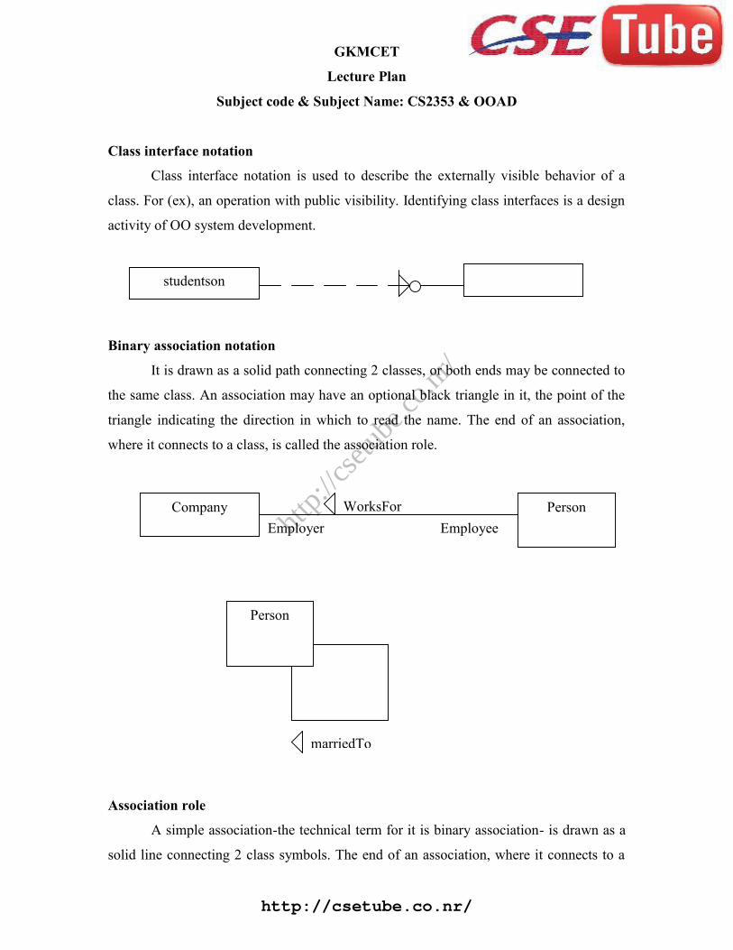
Class interface notation
Class interface notation is used to describe the externally visible behavior of a
class. For (ex), an operation with public visibility. Identifying class interfaces is a design
activity of OO system development.
Binary association notation
It is drawn as a solid path connecting 2 classes, or both ends may be connected to
the same class. An association may have an optional black triangle in it, the point of the
triangle indicating the direction in which to read the name. The end of an association,
where it connects to a class, is called the association role.
Association role
A simple association-the technical term for it is binary association- is drawn as a
solid line connecting 2 class symbols. The end of an association, where it connects to a
Company Person
Person
Employer Employee
marriedTo
WorksFor
studentson
http://csetube.co.nr/
http:/
/csetu
be.co
.nr/
GKMCET
Lecture Plan
Subject code & Subject Name: CS2353 & OOAD
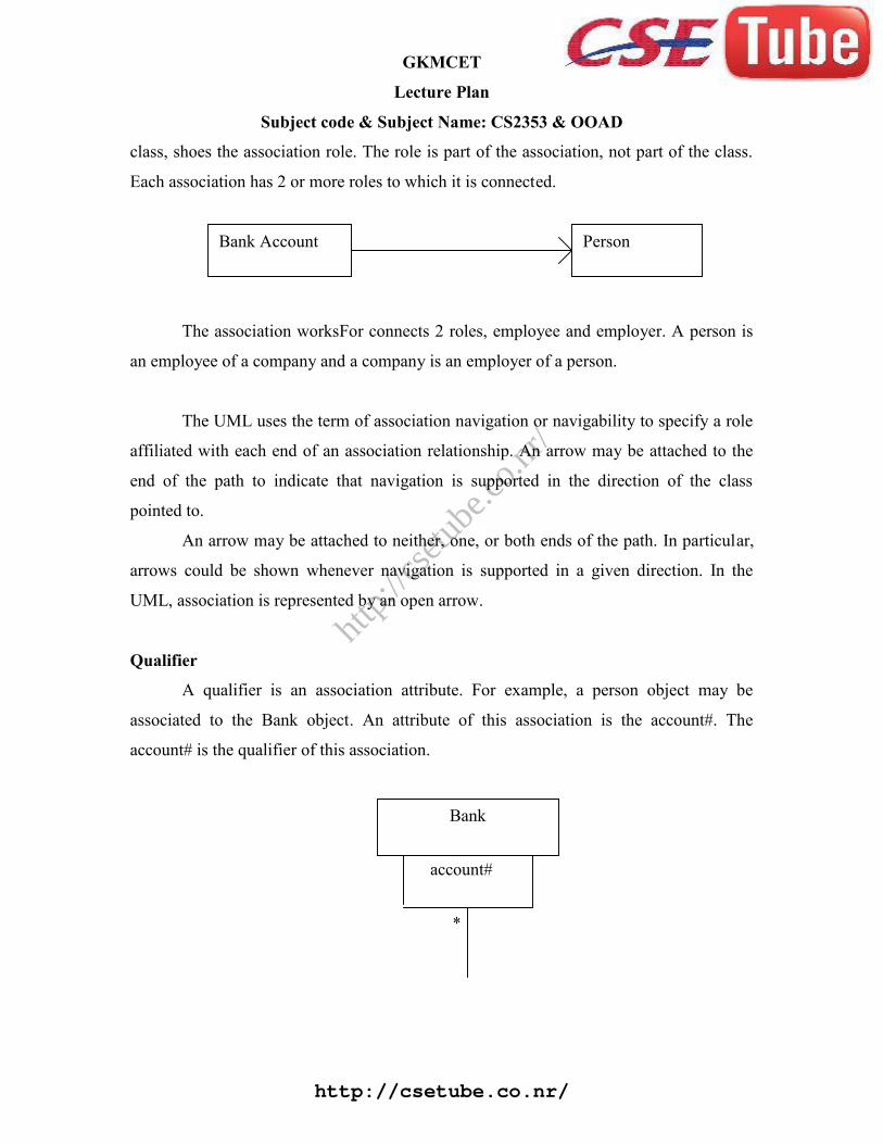
class, shoes the association role. The role is part of the association, not part of the class.
Each association has 2 or more roles to which it is connected.
The association worksFor connects 2 roles, employee and employer. A person is
an employee of a company and a company is an employer of a person.
The UML uses the term of association navigation or navigability to specify a role
affiliated with each end of an association relationship. An arrow may be attached to the
end of the path to indicate that navigation is supported in the direction of the class
pointed to.
An arrow may be attached to neither, one, or both ends of the path. In particular,
arrows could be shown whenever navigation is supported in a given direction. In the
UML, association is represented by an open arrow.
Qualifier
A qualifier is an association attribute. For example, a person object may be
associated to the Bank object. An attribute of this association is the account#. The
account# is the qualifier of this association.
account#
Bank Account Person
Bank
*
http://csetube.co.nr/

http:/
/csetu
be.co
.nr/
GKMCET
Lecture Plan
Subject code & Subject Name: CS2353 & OOAD
A qualifier is shown as a small rectangle attached to the end of an association
path, between the final path segment and the symbol of the class to which it connects.
The qualifier rectangle is part of the association path, not part of the class. The qualifier
rectangle usually is smaller than the attached class rectangle.
Multiplicity
It specifies the range of allowable association classes. An interval represents a
range of integers in this format,
Lower bound…… upper bound.
The term lower bound and upper bound are integer values, specifying the range of
integers including the lower bound to the upper bound. The star character (*) may be
used for the upper bound, denoting an unlimited upper bound. If a single integer value is
specified, then the integer range contains the single values. For example,
0…..1
0……*
1….3, 7….10, 15,19….*
OR Association
An OR association indicates a situation in which only one of several potential
association may be instantiated at one time for any single object. This is shown as a
dashed line connecting 2 or more associations, all of which must have a class in common,
with the constraint string or labeling the dashed line.
or
Person0…1
Car
Person
Companyhttp://csetube.co.nr/

http:/
/csetu
be.co
.nr/
GKMCET
Lecture Plan
Subject code & Subject Name: CS2353 & OOAD
Association class
An association class is an association that also class properties. An association
class is shown as a class symbol attached by a dashed line to an association path.
N-ary association
An n-ary association is an association among more than two classes. Since n-ary
association is more difficult to understand, it is better to convert an n-ary association to
binary association.
However, here, for the sake of completeness, we cover the notation of n-ary
association; an n-ary association is shown as a large diamond with a path from the
diamond to each participant class.
The name of the association (if any) is shown near the diamond.
Company Person
Works for
Salary
Employer Employee
http://csetube.co.nr/
http:/
/csetu
be.co
.nr/
GKMCET
Lecture Plan
Subject code & Subject Name: CS2353 & OOAD
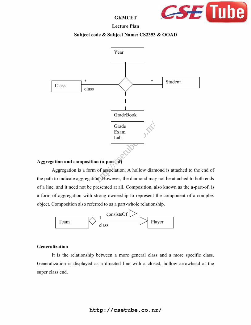
Aggregation and composition (a-part-of)
Aggregation is a form of association. A hollow diamond is attached to the end of
the path to indicate aggregation. However, the diamond may not be attached to both ends
of a line, and it need not be presented at all. Composition, also known as the a-part-of, is
a form of aggregation with strong ownership to represent the component of a complex
object. Composition also referred to as a part-whole relationship.
Generalization
It is the relationship between a more general class and a more specific class.
Generalization is displayed as a directed line with a closed, hollow arrowhead at the
super class end.
Year
ClassStudent
GradeBook
GradeExamLab
class* *
Team Playerclass1
consistsOf
http://csetube.co.nr/

http:/
/csetu
be.co
.nr/
GKMCET
Lecture Plan
Subject code & Subject Name: CS2353 & OOAD
Ellipses (….) indicate that the generalization is incomplete and more subclasses
exist that are not shown.
UML Interaction DiagramsInteraction diagrams are diagrams that describe how groups of objects collaborate
to get the job done. Interaction diagrams capture the behavior of a single use case,
showing the pattern of interaction among objects. There are 2 kinds of interaction
models,
1. Sequence diagrams
2. Collaboration diagrams
UML Sequence Diagram
A sequence diagram shows an interaction arranged in a time sequence. It shows
the objects participating in the interaction by their lifelines and the messages they
exchange, arranged in a time sequence.
A sequence diagram has two dimensions,
Vertical dimension represents time
Horizontal dimension represents different objects.
Vehicle
Bus Truck Car
http://csetube.co.nr/

http:/
/csetu
be.co
.nr/
GKMCET
Lecture Plan
Subject code & Subject Name: CS2353 & OOAD
The vertical line is called the object’s lifeline. The lifeline represents the object’s
existence during the interaction. This form was first popularized by Jacobson. An object
is shown as a box at the top of a dashed vertical line. A role is a slot for an object within a
collaboration that describes the type of object that may play the role and its relationships
to other roles.
An example of a sequence diagram
Telephone call
A sequence diagram does not show the relationship among the roles or the
association among the objects. An object role is shown as a vertical line, the lifeline.
Each message is represented by an arrow between the lifelines of two objects. The
order in which these messages occur is shown top to bottom on the page. Each message is
labeled with the message name. The label also can include the argument and some
callerExchange Receiver Talk
OffHook
DialTone
DialNumberRing Tone
OffHook
OnHook
http://csetube.co.nr/

http:/
/csetu
be.co
.nr/
GKMCET
Lecture Plan
Subject code & Subject Name: CS2353 & OOAD
control information and show-delegation, a message that an object sends to itself, by
sending the message arrow back to the same lifeline.
The horizontal ordering of the lifelines is arbitrary. Often, call arrows are
arranged to process in one direction across the page, but this is not always possible and
the order conveys no information.
Advantages
1. The sequence diagram is very simple and has immediate visual appeal-
this is its great strength.
2. A sequence diagram is an alternative way to understand the overflow of
the control of a program.
3. Instead of looking at the code and trying to find out the overall sequence
of behavior, you can use the sequence diagram to quickly understand that
sequence
Strengths
Clearly shows sequence or time ordering of messages.
Simple notation
Weakness
Forced to extend to the right when adding new objects, consumes
horizontal space.
http://csetube.co.nr/

http:/
/csetu
be.co
.nr/
GKMCET
Lecture Plan
Subject code & Subject Name: CS2353 & OOAD
Unit Number: IV
GRASP: Designing Objects with Responsibilities Creator
Information expert
Low coupling
Controller
High cohesion
Creator
Creator guides the assigning of responsibilities related to the creation of objects,
a very common task. The basic intent of the creator pattern is to find a creator that
needs to be connected to the created object in any event. Choosing it as the creator
supports low coupling.
Composite aggregates part, container contains content, and recorder records.
Recorded are all very common relationships between classes in a class diagram.
Creator suggests that the enclosing container or recorder class is a good candidate for
the responsibility of creating the thing contained or recorded. Of course this is only a
guideline.
Contraindications
Creation requires significant complexity, such as using recycled instances for
performance, conditionally creating an instance from one of a family of similar classes
based upon some external property value, and so forth. In these cases, it is advisable to
delegate creation to a helper class called concrete factory or an abstract factory rather
than use the class suggested by creator.
http://csetube.co.nr/

http:/
/csetu
be.co
.nr/
GKMCET
Lecture Plan
Subject code & Subject Name: CS2353 & OOAD
Benefits
Low coupling is supported, which implies maintenance dependencies
and higher opportunities for reuse.
Coupling is probably not increased because the created class is likely
already visible to the creator class, due to the existing association that
motivated its choice as creator.
Related patterns of principle
Low coupling
Concrete factory and abstract factory
Whole – part describes a pattern to define aggregate objects that support
encapsulation of components.
Information expert (or expert)
Information expert is frequently used in the assignment of responsibilities, it is a
basic guiding principle used continuously in object design. Expert is not meant to be an
obscure or fancy idea, it expresses the common “intuition” that objects do things related
to the information they have.
Expert usually leads to designs where a software object does those operations
that are normally done to the inanimate real-world thing in represents, peter coad calls
this the “do it myself” strategy.
The information expert pattern- like many things in object technology- has a
real-world analogy. We commonly give responsibility to individuals who have the
information necessary to fulfill a task.
http://csetube.co.nr/

http:/
/csetu
be.co
.nr/
GKMCET
Lecture Plan
Subject code & Subject Name: CS2353 & OOAD
Benefits
Information encapsulation is maintained.
This usually supports low coupling, which leads to more robust and
maintainable systems. Low coupling is also a GRASP pattern
Behavior is distributed across the classes that have the required information,
thus encouraging more cohesive “lightweight” class definitions that are easier to
understand and maintain.
High cohesion is usually supported.
Related patterns of principles
Low coupling
High cohesion
Low coupling
It is a principle to keep in mind during all design decisions; it is an underlying
goal to continually consider. It is an evaluative principle that you apply while
evaluating all design decisions.
It encourages you to assign a responsibility so that its placement does not
increase the coupling to a level that leads to the negative results that high coupling can
produce.
Low coupling supports the design of classes that are more independent, which
reduces the impact of change. It can’t be considered in isolation from other patterns
such as expert and high cohesion, but rather needs to be included as one of several
design principles that influence a choice in assigning a responsibility. A subclass is
strongly coupled to its super class.
The disadvantage of this sub classing is that it highly couples domain objects to
a particular technical service and mixes different architectural concerns, whereas the
advantage is automatic inheritance of persistence behavior.
http://csetube.co.nr/

http:/
/csetu
be.co
.nr/
GKMCET
Lecture Plan
Subject code & Subject Name: CS2353 & OOAD
Benefits
Not affected by changes in other components
Simple to understand in isolation
Convenient to reuse
Related patterns
Protected variation
Controller
See also: Model view controller
The Controller pattern assigns the responsibility of dealing with system events to a
non-UI class that represent the overall system or a use case scenario. A Controller object
is a non-user interface object responsible for receiving or handling a system event.
A use case controller should be used to deal with all system events of a use case, and
may be used for more than one use case (for instance, for use cases Create User and
Delete User, one can have one User Controller, instead of two separate use case
controllers).
It is defined as the first object beyond the UI layer that receives and coordinates
("controls") a system operation. The controller should delegate to other objects the work
that needs to be done; it coordinates or controls the activity. It should not do much work
itself. The GRASP Controller can be thought of as being a part of the Application/Service
layer in an object-oriented system with common layers.
A Controller is the first object beyond the UI layer that is responsible for receiving
or handling a system operation message. A common defect in the design of controllers’
results from over- assignment of responsibility. A controller then suffers from bad
http://csetube.co.nr/

http:/
/csetu
be.co
.nr/
GKMCET
Lecture Plan
Subject code & Subject Name: CS2353 & OOAD
(low) cohesion, violating the principle of high cohesion. Normally, a controller delegate
to other objects the work that needs to be done; it coordinates or controls the activity. It
does not do much work itself.
Benefits
Increased potential for reuse and pluggable interfaces
Opportunity to reason about the state of the use case
High cohesion
High Cohesion is an evaluative pattern that attempts to keep objects
appropriately focused, manageable and understandable. High cohesion is generally
used in support of Low Coupling. High cohesion means that the responsibilities of a
given element are strongly related and highly focused. Breaking programs into classes
and subsystems is an example of activities that increase the cohesive properties of a
system. Alternatively, low cohesion is a situation in which a given element has too
many unrelated responsibilities. Elements with low cohesion often suffer from being
hard to comprehend, hard to reuse, hard to maintain and adverse to change
Like low coupling, high cohesion is a principle to keep in mind during all
design decisions; it is an underlying goal to continually consider. It is an evaluative
principle that a designer applies while evaluating all design decisions.
Degrees of functional cohesion
Very low cohesion
http://csetube.co.nr/

http:/
/csetu
be.co
.nr/
GKMCET
Lecture Plan
Subject code & Subject Name: CS2353 & OOAD
Low cohesion
High cohesion
Moderate cohesion
Designing for visibilityVisibility is the ability of one object to see or have reference to another.
When is visibility necessary?
To send a message from one object to another, the receiver object must be visible
to the sender, so the sender has to have a pointer or reference to the receiver.
Example:
If A sends messages to B, which must be visible to which?
B is visible to A means A can send a message to B.
http://csetube.co.nr/

http:/
/csetu
be.co
.nr/
GKMCET
Lecture Plan
Subject code & Subject Name: CS2353 & OOAD
Visibility — the ability of one object to “see” or have a reference to another
Object.
Visibility is required for one object to message another
Attribute Visibility — Y is an attribute of ClassX
Parameter Visibility — Y is a parameter of MethodX
Local Visibility — Y is a (non-parameter) local object in a method of ClassX
Global Visibility — Y is globally visible (language dependent)
Applying GOF design pattern
Singleton Pattern (Gang of Four)
The singleton pattern is a design pattern used to implement the mathematical concept of a singleton, by
restricting the instantiation of a class to one object. This is useful when exactly one object is needed to
coordinate actions across the system. The concept is sometimes generalized to systems that operate more
efficiently when only one object exists, or that restrict the instantiation to a certain number of objects.
Problem:
Exactly one instance of a class is needed. Objects need a single point of
access.
Solution:
Define a class method that returns the singleton object, instantiating it if
it does not exist.
Example:
A print queue—many programs must access one queue.
Illustrating Visibility in the UML
http://csetube.co.nr/

http:/
/csetu
be.co
.nr/
GKMCET
Lecture Plan
Subject code & Subject Name: CS2353 & OOAD
The Observer pattern is usually used in combination with other design patterns:
Factory pattern - It's very likely to use the factory pattern to create the Observers so no
changes will be required even in the main framework. The new observers can be added directly
in the configuration files.
Template Method - The observer pattern can be used in conjunction
with the Template Method Pattern to make sure that Subject state is self-consistent before
notification
Mediator Pattern - The mediator pattern can be used when we have cases of complex
cases of many subjects an many observers
http://csetube.co.nr/

http:/
/csetu
be.co
.nr/
GKMCET
Lecture Plan
Subject code & Subject Name: CS2353 & OOAD
The Observer Pattern
The Observer pattern assumes that the object containing the data is separate from
the objects that display the data, and that these display objects observe changes in that
data. When we implement the Observer pattern, we usually refer to the data as the
Subject and each of the displays as Observers. Each of these observers registers its
interest in the data by calling a public method in the Subject. Then, each observer has a
known interface that the subject calls when the data change.
http://csetube.co.nr/

http:/
/csetu
be.co
.nr/
GKMCET
Lecture Plan
Subject code & Subject Name: CS2353 & OOAD
Unit Number: V
UML state or state chart diagrams and modelingA state chart diagram (also called a state diagram) shows the sequence of states
that an object goes through during its life in response to outside stimuli and messages.
The state is the set of values that describes an object at a specific point in time and is
represented by state symbols and the transitions are represented by arrows connecting the
state symbols. A state chart diagram may contain sub diagrams.
A state diagram represents the state of the method execution (that is, the state of
the object executing the method) and the activities in the diagram represent the activities
of the object that performs the method.
The purpose of the state diagram is to understand the algorithm involved in
performing a method.
A state is represented as a rounded box, which may contain one or more
compartments. The compartments are all optional.
The name compartment holds the optional name of the state.
The internal transition compartment holds a list of internal actions
or activities.
An initial state is shown as a small dot and the transition from the initial state
may be labeled with the event that creates the objects, otherwise, it is unlabeled.
http://csetube.co.nr/
http:/
/csetu
be.co
.nr/
GKMCET
Lecture Plan
Subject code & Subject Name: CS2353 & OOAD
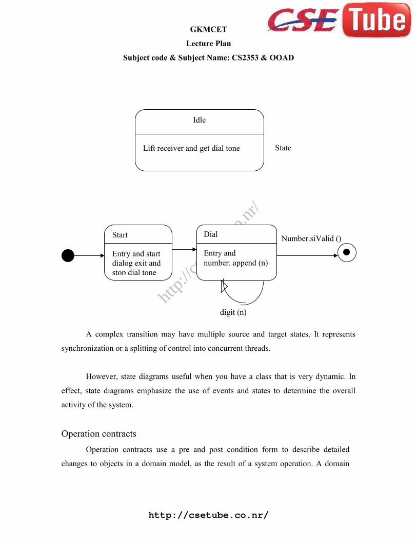
A complex transition may have multiple source and target states. It represents
synchronization or a splitting of control into concurrent threads.
However, state diagrams useful when you have a class that is very dynamic. In
effect, state diagrams emphasize the use of events and states to determine the overall
activity of the system.
Operation contractsOperation contracts use a pre and post condition form to describe detailed
changes to objects in a domain model, as the result of a system operation. A domain
Dial
Entry andnumber. append (n)
Start
Entry and startdialog exit andstop dial tone
Number.siValid ()
digit (n)
Idle
Lift receiver and get dial tone State
http://csetube.co.nr/

http:/
/csetu
be.co
.nr/
GKMCET
Lecture Plan
Subject code & Subject Name: CS2353 & OOAD
model is the most common OOA model, but the operation contracts and state models
can also be useful OOA- related artifacts.
Operation contracts may be considered part of the UP use-case model because
they provide more analysis detail on the effect of the system operations implied in the
use cases. See fig- 11.1 in pg.no-182.
Definition: what are the sections of a contract?
Operation: name of operation, and parameters
Cross references: use cases this operation can occur within
Preconditions: noteworthy assumptions about the state of the system or
objects in the domain model before execution of the operation. These are
non-trivial assumptions the reader should be told.
Post conditions: this is the most important section. The state of objects
in the domain model after completion of the operation.
Definition: what is a system operation?
Operation contracts may be defined for system operations- operations that
the system as a black box component offers in its public interface. System
operations can be identified.
Definition: post conditions
The post conditions describe changes in the state of objects in the domain
model. Domain model state changes include instances created, associations formed or
broken, and attributes changed.
Post conditions are not actions to be performed during the operation, rather
they are observations about the domain model objects that are true when the operation
has finished- after the smoke has cleared. The post conditions fall into these
categories,
1 Instance creation and deletion
http://csetube.co.nr/

http:/
/csetu
be.co
.nr/
GKMCET
Lecture Plan
Subject code & Subject Name: CS2353 & OOAD
2 Attribute change of value
3 Association formed and broken
How are post conditions related to the domain model?
Motivation: why post conditions?
Guideline: how to write a post condition?
Analogy: the spirit of post conditions: the stage and curtain
Guideline: how complete should post conditions be? Agile vs. heavy
analysis
Guideline: should we update the domain model?
In iterative and evolutionary methods (and reflecting the reality of software
projects), all analysis and design artifacts are considered partial and imperfect, and
evolve in response to new discoveries.
Guideline: when are contracts useful?
Guideline: how to create and write contracts
Apply the following advice to create contracts:
1. Identify system operations from the SSDs.
2. For system operations that are complex and perhaps subtle in their results, or
which are not clear in the use case, construct a contract.
3. To describe the post conditions, use the following categories:
Instance creation and deletion
Attribute modification
Associations formed and broken
http://csetube.co.nr/

http:/
/csetu
be.co
.nr/
GKMCET
Lecture Plan
Subject code & Subject Name: CS2353 & OOAD
Applying UML: operations, contracts, and the OCL
The UML formally defines operations. To quote:
An operation is a specification of a transformation or query that an object may be called
to execute.
In the UML Meta model, an operation has a signature and most importantly in
this context, is associated with a set of UML constraint objects classified as pre
conditions and post conditions that specify the semantics of the operation.
Operation contracts expressed with the OCL
The pre and post condition format is informal natural language- perfectly
acceptable in the UML and desirable to be easily understood.
But also associated with the UML is a formal, rigorous language called the Object
Constraint Language (OCL), which can be used to express constraints of UML
operations.
Process: operation contracts within the UP
A pre and pos condition contract is a well-known style to specify an operation in
the UML. In the UML, operations exist at many levels, from System down to fine-
grained classes, such as sale.
Operation contracts for the System level are part of the use-case model, although
they were not formally highlighted in the original RUP or UP documentation, their
inclusion in this model was verified with the RUP authors.
Phases
Inception – contracts are not motivated during inception- they are too detailed
http://csetube.co.nr/

http:/
/csetu
be.co
.nr/
GKMCET
Lecture Plan
Subject code & Subject Name: CS2353 & OOAD
Elaboration- if used at all, most contracts will be written during elaboration,
when most use cases are written. Only write contracts for the most complex and subtle
system operations.
Mapping design to codeImplementation in an OO language requires writing source code for:
Class and interface definitions
Method definitions
Creating class definitions from DCDs
DCDs depict the class or interface name, super class, operation signatures, and
attributes of a class. This is sufficient to create a basis class definition in an OO
language. If the DCDs were drawn in a UML tool, it can generate the basic class
definition from the diagrams.
Creating methods from interaction diagrams
The sequence of the messages in an interaction diagram translates to series of
statements in the method definitions.
Collection classes in code
One- to - many relationships are common. The choice of collection class is of
course influenced by the requirements, key based lookup requires the use of a map, a
growing ordered list requires a list, and so on.
Guideline:
If an object implements an interface, declare the variable in terms of the
interface, not the concrete class.
http://csetube.co.nr/

http:/
/csetu
be.co
.nr/
GKMCET
Lecture Plan
Subject code & Subject Name: CS2353 & OOAD
Exceptions and error handling
Exception handling has been ignored so far in the development of a solution.
This was intentional to focus on the basic questions of responsibility assignment and
object design. However, in application development, it’s wise to consider the logic-
scale exception handling strategies during design modeling and certainly during
implementation. Briefly, in terms of the UML, exceptions can be indicated in the
property strings of messages and operation declarations
Defining the Sale.makeLineItem method
Order of implementation
Test driven or test-first development
UML deployment and component diagrams
Deployment diagrams
A deployment diagram shows the assignment of concrete software artifacts (such
as executable files) to computational nodes (something with processing services).
It shows the deployment of software elements to the physical architecture and the
communication between physical elements. See figure 38.1. Deployment diagrams are
useful to communicate the physical or deployment architecture.
The basic elements of a deployment diagram are a node, of two types:
http://csetube.co.nr/

http:/
/csetu
be.co
.nr/
GKMCET
Lecture Plan
Subject code & Subject Name: CS2353 & OOAD
Device node (or device)
Execution environment node (EEN)
The notation in a deployment diagram includes the notation elements used in a
component diagram, with a couple of additions, including the concept of a node. A node
represents either a physical machine or a virtual machine node (e.g., a mainframe node).
To model a node, simply draw a three-dimensional cube with the name of the
node at the top of the cube. Use the naming convention used in sequence diagrams.
The three-dimensional boxes represent nodes, either software or hardware.
Physical nodes should be labeled with the stereotype device, to indicate that it is a
physical device such as a computer or switch.
Connections between nodes are represented with simple lines, and are assigned
stereotypes such as RMI and message bus to indicate the type of connection.
http://csetube.co.nr/

http:/
/csetu
be.co
.nr/
GKMCET
Lecture Plan
Subject code & Subject Name: CS2353 & OOAD
Component diagramsComponent diagrams are a slightly fuzzy concept in the UML, because both
classes and components can be used to model the same thing.
A component represents a modular part of a system that encapsulates its contents
and whose manifestation is replaceable within its environment.
A component defines its behavior in terms of provided and required interfaces. As
such, a component serves as a type, whose conformance is defined by these provided and
required interfaces.
http://csetube.co.nr/