cs152 / kubiatowicz lec23.1 11/22/99©ucb fall 1999 cs152 computer architecture and engineering...
Post on 20-Dec-2015
220 views
TRANSCRIPT

11/22/99 ©UCB Fall 1999 CS152 / Kubiatowicz
Lec23.1
CS152Computer Architecture and Engineering
Lecture 23
Busses (continued)I/O Systems
November 22, 1999
John Kubiatowicz (http.cs.berkeley.edu/~kubitron)
lecture slides: http://www-inst.eecs.berkeley.edu/~cs152/

11/22/99 ©UCB Fall 1999 CS152 / Kubiatowicz
Lec23.2
The Big Picture: Where are We Now?
Control
Datapath
Memory
Processor
Input
Output
° Today’s Topic: I/O Systems
Control
Datapath
Memory
Processor
Input
Output
Network/Bus

11/22/99 ©UCB Fall 1999 CS152 / Kubiatowicz
Lec23.3
Outline of Today’s Lecture
° Recap/Finish up with Buses
° I/O Performance Measures
° Some Queueing Theory
° Types and Characteristics of I/O Devices
° Magnetic Disks
° DMA, Multimedia, OS
° Summary

11/22/99 ©UCB Fall 1999 CS152 / Kubiatowicz
Lec23.4
Recap: Busses
° Fundamental tool for designing and building computer systems
• divide the problem into independent components operating against a well defined interface
• compose the components efficiently
° Shared collection of wires
• command, address, data
° Communication path between multiple subsystems
• Inexpensive
• Limited bandwidth
° Layers of a bus specification
• mechanical, electrical, signaling, timing, transactions
° ° °Master Slave
Control LinesAddress Lines
Data Lines

11/22/99 ©UCB Fall 1999 CS152 / Kubiatowicz
Lec23.5
Recap: North/South Bridge architectures: separate buses
° Separate sets of pins for different functions• Memory bus • Caches• Graphics bus (for fast frame buffer)• I/O buses are connected to the backplane bus
° Advantage: • Buses can run at different speeds• Much less overall loading!
Processor MemoryProcessor Memory Bus
BusAdaptor
BusAdaptor
I/O BusBackplane Bus
I/O Bus
“backsidecache”

11/22/99 ©UCB Fall 1999 CS152 / Kubiatowicz
Lec23.6
° Arbitration: Who gets the bus
° Request: What do we want to do
° Action: What happens in response
Recap: Bus Transaction

11/22/99 ©UCB Fall 1999 CS152 / Kubiatowicz
Lec23.7
° One of the most important issues in bus design:• How is the bus reserved by a device that wishes to use it?
° Chaos is avoided by a master-slave arrangement:• Only the bus master can control access to the bus:
It initiates and controls all bus requests
• A slave responds to read and write requests
° The simplest system:• Processor is the only bus master
• All bus requests must be controlled by the processor
• Major drawback: the processor is involved in every transaction
BusMaster
BusSlave
Control: Master initiates requests
Data can go either way
Arbitration: Obtaining Access to the Bus

11/22/99 ©UCB Fall 1999 CS152 / Kubiatowicz
Lec23.8
Multiple Potential Bus Masters: the Need for Arbitration
° Bus arbitration scheme:• A bus master wanting to use the bus asserts the bus request
• A bus master cannot use the bus until its request is granted
• A bus master must signal to the arbiter after finish using the bus
° Bus arbitration schemes usually try to balance two factors:• Bus priority: the highest priority device should be serviced first
• Fairness: Even the lowest priority device should never be completely locked out from the bus
° Bus arbitration schemes can be divided into four broad classes:
• Daisy chain arbitration
• Centralized, parallel arbitration
• Distributed arbitration by self-selection: each device wanting the bus places a code indicating its identity on the bus.
• Distributed arbitration by collision detection: Each device just “goes for it”. Problems found after the fact.

11/22/99 ©UCB Fall 1999 CS152 / Kubiatowicz
Lec23.9
The Daisy Chain Bus Arbitrations Scheme
° Advantage: simple
° Disadvantages:• Cannot assure fairness:
A low-priority device may be locked out indefinitely
• The use of the daisy chain grant signal also limits the bus speed
BusArbiter
Device 1HighestPriority
Device NLowestPriority
Device 2
Grant Grant Grant
Release
Request
wired-OR

11/22/99 ©UCB Fall 1999 CS152 / Kubiatowicz
Lec23.10
° Used in essentially all processor-memory busses and in high-speed I/O busses
BusArbiter
Device 1 Device NDevice 2
Grant Req
Centralized Parallel Arbitration

11/22/99 ©UCB Fall 1999 CS152 / Kubiatowicz
Lec23.11
° All agents operate synchronously
° All can source / sink data at same rate
° => simple protocol
• just manage the source and target
Simplest bus paradigm

11/22/99 ©UCB Fall 1999 CS152 / Kubiatowicz
Lec23.12
° Even memory busses are more complex than this• memory (slave) may take time to respond
• it may need to control data rate
BReq
BG
Cmd+AddrR/WAddress
Data1 Data2Data
Simple Synchronous Protocol

11/22/99 ©UCB Fall 1999 CS152 / Kubiatowicz
Lec23.13
° Slave indicates when it is prepared for data xfer
° Actual transfer goes at bus rate
BReq
BG
Cmd+AddrR/WAddress
Data1 Data2Data Data1
Wait
Typical Synchronous Protocol
11/22/99 ©UCB Fall 1999 CS152 / Kubiatowicz
Lec23.14
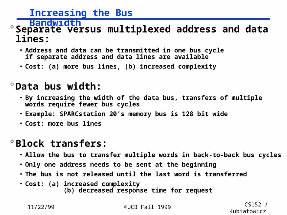
° Separate versus multiplexed address and data lines:• Address and data can be transmitted in one bus cycle
if separate address and data lines are available
• Cost: (a) more bus lines, (b) increased complexity
° Data bus width:• By increasing the width of the data bus, transfers of multiple words require fewer bus
cycles
• Example: SPARCstation 20’s memory bus is 128 bit wide
• Cost: more bus lines
° Block transfers:• Allow the bus to transfer multiple words in back-to-back bus cycles
• Only one address needs to be sent at the beginning
• The bus is not released until the last word is transferred
• Cost: (a) increased complexity (b) decreased response time for request
Increasing the Bus Bandwidth

11/22/99 ©UCB Fall 1999 CS152 / Kubiatowicz
Lec23.15
° Overlapped arbitration• perform arbitration for next transaction during current transaction
° Bus parking• master can holds onto bus and performs multiple transactions as long
as no other master makes request
° Overlapped address / data phases (prev. slide)• requires one of the above techniques
° Split-phase (or packet switched) bus• completely separate address and data phases
• arbitrate separately for each
• address phase yield a tag which is matched with data phase
° ”All of the above” in most modern memory buses
Increasing Transaction Rate on Multimaster Bus

11/22/99 ©UCB Fall 1999 CS152 / Kubiatowicz
Lec23.16
Bus MBus Summit Challenge XDBus
Originator Sun HP SGI Sun
Clock Rate (MHz) 40 60 48 66
Address lines 36 48 40 muxed
Data lines 64 128 256 144 (parity)
Data Sizes (bits) 256 512 1024 512
Clocks/transfer 4 5 4?
Peak (MB/s) 320(80) 960 1200 1056
Master Multi Multi Multi Multi
Arbitration Central Central Central Central
Slots 16 9 10
Busses/system 1 1 1 2
Length 13 inches 12? inches 17 inches
1993 MP Server Memory Bus Survey: GTL revolution

11/22/99 ©UCB Fall 1999 CS152 / Kubiatowicz
Lec23.17
Address
Data
Read
Req
Ack
Master Asserts Address
Master Asserts Data
Next Address
Write Transaction
t0 t1 t2 t3 t4 t5
t0 : Master has obtained control and asserts address, direction, data Waits a specified amount of time for slaves to decode target.
t1: Master asserts request linet2: Slave asserts ack, indicating data receivedt3: Master releases reqt4: Slave releases ack
Asynchronous Handshake

11/22/99 ©UCB Fall 1999 CS152 / Kubiatowicz
Lec23.18
Address
Data
Read
Req
Ack
Master Asserts Address Next Address
t0 t1 t2 t3 t4 t5
t0 : Master has obtained control and asserts address, direction, data Waits a specified amount of time for slaves to decode target.
t1: Master asserts request linet2: Slave asserts ack, indicating ready to transmit datat3: Master releases req, data receivedt4: Slave releases ack
Read Transaction
Slave Data

11/22/99 ©UCB Fall 1999 CS152 / Kubiatowicz
Lec23.19
Bus SBus TurboChannel MicroChannel PCI
Originator Sun DEC IBM Intel
Clock Rate (MHz) 16-25 12.5-25 async 33
Addressing Virtual Physical Physical Physical
Data Sizes (bits) 8,16,32 8,16,24,32 8,16,24,32,648,16,24,32,64
Master Multi Single Multi Multi
Arbitration Central Central Central Central
32 bit read (MB/s) 33 25 20 33
Peak (MB/s) 89 84 75 111 (222)
Max Power (W) 16 26 13 25
1993 Backplane/IO Bus Survey
11/22/99 ©UCB Fall 1999 CS152 / Kubiatowicz
Lec23.20
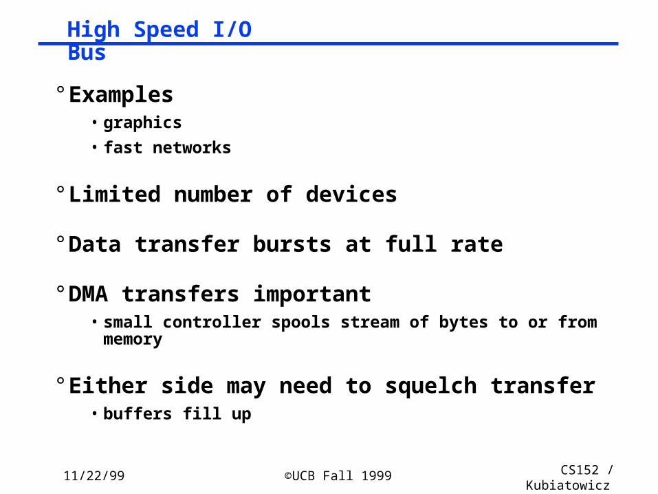
° Examples• graphics
• fast networks
° Limited number of devices
° Data transfer bursts at full rate
° DMA transfers important• small controller spools stream of bytes to or from memory
° Either side may need to squelch transfer• buffers fill up
High Speed I/O Bus

11/22/99 ©UCB Fall 1999 CS152 / Kubiatowicz
Lec23.21
° All signals sampled on rising edge
° Centralized Parallel Arbitration• overlapped with previous transaction
° All transfers are (unlimited) bursts
° Address phase starts by asserting FRAME#
° Next cycle “initiator” asserts cmd and address
° Data transfers happen on when• IRDY# asserted by master when ready to transfer data
• TRDY# asserted by target when ready to transfer data
• transfer when both asserted on rising edge
° FRAME# deasserted when master intends to complete only one more data transfer
PCI Read/Write Transactions

11/22/99 ©UCB Fall 1999 CS152 / Kubiatowicz
Lec23.22
– Turn-around cycle on any signal driven by more than one agent
PCI Read Transaction

11/22/99 ©UCB Fall 1999 CS152 / Kubiatowicz
Lec23.23
PCI Write Transaction

11/22/99 ©UCB Fall 1999 CS152 / Kubiatowicz
Lec23.24
° Push bus efficiency toward 100% under common simple usage
• like RISC
° Bus Parking• retain bus grant for previous master until another makes request• granted master can start next transfer without arbitration
° Arbitrary Burst length• initiator and target can exert flow control with xRDY• target can disconnect request with STOP (abort or retry)• master can disconnect by deasserting FRAME• arbiter can disconnect by deasserting GNT
° Delayed (pended, split-phase) transactions• free the bus after request to slow device
PCI Optimizations

11/22/99 ©UCB Fall 1999 CS152 / Kubiatowicz
Lec23.25
Summary
° Buses are an important technique for building large-scale systems
• Their speed is critically dependent on factors such as length, number of devices, etc.
• Critically limited by capacitance• Tricks: esoteric drive technology such as GTL
° Important terminology:• Master: The device that can initiate new transactions• Slaves: Devices that respond to the master
° Two types of bus timing:• Synchronous: bus includes clock• Asynchronous: no clock, just REQ/ACK strobing
° Direct Memory Access (dma) allows fast, burst transfer into processor’s memory:
• Processor’s memory acts like a slave• Probably requires some form of cache-coherence so that DMA’ed
memory can be invalidated from cache.

11/22/99 ©UCB Fall 1999 CS152 / Kubiatowicz
Lec23.26
Administrivia I
° Midterm II results: • Mean: 67.8
• Std Dev: 12.6
CS152 Midterm II
0
1
2
3
4
5
6
7
8
9
10 20 30 40 45 50 55 60 65 70 75 80 85 90 95

11/22/99 ©UCB Fall 1999 CS152 / Kubiatowicz
Lec23.27
Administrivia I° Problem I tedious but not difficult:• Trick on cache simulation problem was to write address in binary
and cross out bits below cache-line boundary: word size was 16 bytes, so you wanted to cross out 4
bits. There were 16 sets, so middle nibble was key
• On Average memory access time problem, solution is recursive:- AMATL1-data=TL1-hit+MissRatedataAMATL2
- AMATL2=TL2-hit+MissRateL2AMATDRAM etc, recursively!
- Where TL2-hit= time to fill L1 cache from L2 we also called this TL1-penalty in classComponent Hit Time Miss Rate Block Size
First-LevelCache
1 cycle4% Data
1% Instructions64 bytes
Second-LevelCache
20 cycles +1 cycle/64bits
2% 128 bytes
DRAM100ns+
25ns/8 bytes1% 16K bytes
DISK50ms +
20ns/byte0% 16K bytes

11/22/99 ©UCB Fall 1999 CS152 / Kubiatowicz
Lec23.28
Administrivia II
° Problem II: People had a bit more trouble than expected• In-order! Short operations get passed through later stages• Must forward from all later stages to earlier stage!• Special forwarding required for full-throughput stores (bottom of fig)
° Problem IV: • Tomasulo issues in order to maintain dataflow of original code.• Simply lowering clock rates doesn’t usually help battery life (I.e. energy)
D Ex1 Ex2 Ex3 Ex4 Ex5F W
I
Ld,A
I,D,Ld,AI,D,Ld,A
I,D,Ld,A,M
M
I,D
D

11/22/99 ©UCB Fall 1999 CS152 / Kubiatowicz
Lec23.29
Administrivia III
° Important: Design for Test• You should be testing from the very start of your design• Consider adding special monitor modules at various points in
design => I have asked you to label trace output from these modules with the current clock cycle #
• The time to understand how components of your design should work is while you are designing!
° Will get sample test programs out to you soon (today?)° Pending schedule:
• Today: Get description up on web site!• Monday 11/29: Update on design due to TAs• Today 11/22 and Wednesday 11/24: I/O, Queuing Theory, MP?• Monday 11/29: no class -- work on projects.• Wednesday 12/1: Last class (wrap up, evaluations, etc)• Monday 12/6 Oral reports: 10-12am and 2-4pm
- Signup sheet will be on my office door next week- Project reports must be submitted via web by 5pm on 12/6
• Friday 12/10: Grades ready

11/22/99 ©UCB Fall 1999 CS152 / Kubiatowicz
Lec23.30
I/O System Design Issues
Processor
Cache
Memory - I/O Bus
MainMemory
I/OController
Disk Disk
I/OController
I/OController
Graphics Network
interrupts
• Performance
• Expandability
• Resilience in the face of failure

11/22/99 ©UCB Fall 1999 CS152 / Kubiatowicz
Lec23.31
I/O Device Examples
Device Behavior Partner Data Rate (KB/sec)
Keyboard Input Human 0.01
Mouse Input Human 0.02
Line Printer Output Human 1.00
Floppy disk Storage Machine 50.00
Laser Printer Output Human 100.00
Optical Disk Storage Machine 500.00
Magnetic Disk Storage Machine 5,000.00
Network-LAN Input or Output Machine 20 – 1,000.00
Graphics Display Output Human 30,000.00

11/22/99 ©UCB Fall 1999 CS152 / Kubiatowicz
Lec23.32
I/O System Performance
° I/O System performance depends on many aspects of the system (“limited by weakest link in the chain”):
• The CPU
• The memory system:
- Internal and external caches
- Main Memory
• The underlying interconnection (buses)
• The I/O controller
• The I/O device
• The speed of the I/O software (Operating System)
• The efficiency of the software’s use of the I/O devices
° Two common performance metrics:
• Throughput: I/O bandwidth
• Response time: Latency

11/22/99 ©UCB Fall 1999 CS152 / Kubiatowicz
Lec23.33
Simple Producer-Server Model
° Throughput:
• The number of tasks completed by the server in unit time
• In order to get the highest possible throughput:
- The server should never be idle
- The queue should never be empty
° Response time:
• Begins when a task is placed in the queue
• Ends when it is completed by the server
• In order to minimize the response time:
- The queue should be empty
- The server will be idle
Producer ServerQueue

11/22/99 ©UCB Fall 1999 CS152 / Kubiatowicz
Lec23.34
Throughput versus Respond Time
20% 40% 60% 80% 100%
ResponseTime (ms)
100
200
300
Percentage of maximum throughput

11/22/99 ©UCB Fall 1999 CS152 / Kubiatowicz
Lec23.35
Throughput Enhancement
° In general throughput can be improved by:
• Throwing more hardware at the problem
• reduces load-related latency
° Response time is much harder to reduce:
• Ultimately it is limited by the speed of light (but we’re far from it)
Producer
ServerQueue
QueueServer

11/22/99 ©UCB Fall 1999 CS152 / Kubiatowicz
Lec23.36
Disk Capacity now doubles every 18 months; before1990 every 36 months
• Today: Processing Power Doubles Every 18 months
• Today: Memory Size Doubles Every 18 months(4X/3yr)
• Today: Disk Capacity Doubles Every 18 months
• Disk Positioning Rate (Seek + Rotate) Doubles Every Ten Years!
The I/OGAP
The I/OGAP
Technology Trends

11/22/99 ©UCB Fall 1999 CS152 / Kubiatowicz
Lec23.37
° Driven by the prevailing computing paradigm• 1950s: migration from batch to on-line processing
• 1990s: migration to ubiquitous computing
- computers in phones, books, cars, video cameras, …
- nationwide fiber optical network with wireless tails
° Effects on storage industry:• Embedded storage
- smaller, cheaper, more reliable, lower power
• Data utilities
- high capacity, hierarchically managed storage
Storage Technology Drivers

11/22/99 ©UCB Fall 1999 CS152 / Kubiatowicz
Lec23.38
° 1956 IBM Ramac — early 1970s Winchester• Developed for mainframe computers, proprietary interfaces• Steady shrink in form factor: 27 in. to 14 in.
° 1970s developments• 5.25 inch floppy disk formfactor (microcode into mainframe)• early emergence of industry standard disk interfaces
- ST506, SASI, SMD, ESDI
° Early 1980s• PCs and first generation workstations
° Mid 1980s• Client/server computing • Centralized storage on file server
- accelerates disk downsizing: 8 inch to 5.25 inch• Mass market disk drives become a reality
- industry standards: SCSI, IPI, IDE- 5.25 inch drives for standalone PCs, End of proprietary interfaces
Historical Perspective

11/22/99 ©UCB Fall 1999 CS152 / Kubiatowicz
Lec23.39
Data densityMbit/sq. in.
Capacity ofUnit ShownMegabytes
1973:1. 7 Mbit/sq. in140 MBytes
1979:7. 7 Mbit/sq. in2,300 MBytes
source: New York Times, 2/23/98, page C3, “Makers of disk drives crowd even mroe data into even smaller spaces”
Disk History

11/22/99 ©UCB Fall 1999 CS152 / Kubiatowicz
Lec23.40
° Late 1980s/Early 1990s:• Laptops, notebooks, (palmtops)
• 3.5 inch, 2.5 inch, (1.8 inch formfactors)
• Formfactor plus capacity drives market, not so much performance
- Recently Bandwidth improving at 40%/ year
• Challenged by DRAM, flash RAM in PCMCIA cards
- still expensive, Intel promises but doesn’t deliver
- unattractive MBytes per cubic inch
• Optical disk fails on performance (e.g., NEXT) but finds niche (CD ROM)
Historical Perspective

11/22/99 ©UCB Fall 1999 CS152 / Kubiatowicz
Lec23.41
1989:63 Mbit/sq. in60,000 MBytes
1997:1450 Mbit/sq. in2300 MBytes
source: New York Times, 2/23/98, page C3, “Makers of disk drives crowd even more data into even smaller spaces”
1997:3090 Mbit/sq. in8100 MBytes
Disk History

11/22/99 ©UCB Fall 1999 CS152 / Kubiatowicz
Lec23.42
0%
5%
10%
15%
20%
25%
30%
35%
40%
1974 1980 1986 1992 1998
source: New York Times, 2/23/98, page C3, “Makers of disk drives crowd even more data into even smaller spaces”
470 v. 3000 Mb/si
9 v. 22 Mb/si
0.2 v. 1.7 Mb/si
MBits per square inch: DRAM as % of Disk over time

11/22/99 ©UCB Fall 1999 CS152 / Kubiatowicz
Lec23.43
Nano-layered Disk Heads
° Special sensitivity of Disk head comes from “Giant Magneto-Resistive effect” or (GMR)
° IBM is leader in this technology• Same technology as TMJ-RAM breakthrough we described in
earlier class.
Coil for writing

11/22/99 ©UCB Fall 1999 CS152 / Kubiatowicz
Lec23.44
Magnetic Disk
° Purpose:
• Long term, nonvolatile storage
• Large, inexpensive, and slow
• Lowest level in the memory hierarchy
° Two major types:
• Floppy disk
• Hard disk
° Both types of disks:
• Rely on a rotating platter coated with a magnetic surface
• Use a moveable read/write head to access the disk
° Advantages of hard disks over floppy disks:
• Platters are more rigid ( metal or glass) so they can be larger
• Higher density because it can be controlled more precisely
• Higher data rate because it spins faster
• Can incorporate more than one platter
Registers
Cach
e
Mem
ory
Disk

11/22/99 ©UCB Fall 1999 CS152 / Kubiatowicz
Lec23.45
Organization of a Hard Magnetic Disk
° Typical numbers (depending on the disk size):
• 500 to 2,000 tracks per surface
• 32 to 128 sectors per track
- A sector is the smallest unit that can be read or written
° Traditionally all tracks have the same number of sectors:
• Constant bit density: record more sectors on the outer tracks
• Recently relaxed: constant bit size, speed varies with track location
Platters
Track
Sector

11/22/99 ©UCB Fall 1999 CS152 / Kubiatowicz
Lec23.46
Magnetic Disk Characteristic
° Cylinder: all the tacks under the head at a given point on all surface
° Read/write data is a three-stage process:
• Seek time: position the arm over the proper track
• Rotational latency: wait for the desired sectorto rotate under the read/write head
• Transfer time: transfer a block of bits (sector)under the read-write head
° Average seek time as reported by the industry:
• Typically in the range of 8 ms to 12 ms
• (Sum of the time for all possible seek) / (total # of possible seeks)
° Due to locality of disk reference, actual average seek time may:
• Only be 25% to 33% of the advertised number
SectorTrack
Cylinder
HeadPlatter
11/22/99 ©UCB Fall 1999 CS152 / Kubiatowicz
Lec23.47
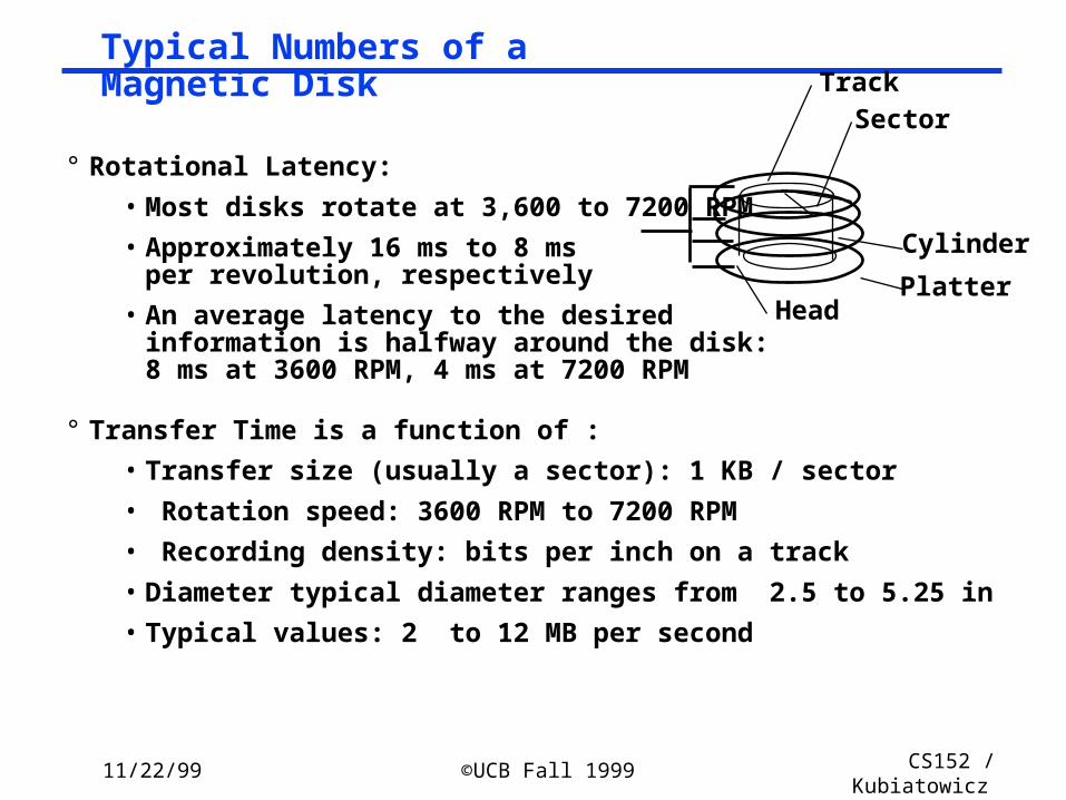
Typical Numbers of a Magnetic Disk
° Rotational Latency:
• Most disks rotate at 3,600 to 7200 RPM
• Approximately 16 ms to 8 ms per revolution, respectively
• An average latency to the desiredinformation is halfway around the disk: 8 ms at 3600 RPM, 4 ms at 7200 RPM
° Transfer Time is a function of :
• Transfer size (usually a sector): 1 KB / sector
• Rotation speed: 3600 RPM to 7200 RPM
• Recording density: bits per inch on a track
• Diameter typical diameter ranges from 2.5 to 5.25 in
• Typical values: 2 to 12 MB per second
SectorTrack
Cylinder
HeadPlatter

11/22/99 ©UCB Fall 1999 CS152 / Kubiatowicz
Lec23.48
Disk I/O Performance
° Disk Access Time = Seek time + Rotational Latency + Transfer time
+ Controller Time + Queueing Delay
° Estimating Queue Length:
• Utilization = U = Request Rate / Service Rate
• Mean Queue Length = U / (1 - U)
• As Request Rate -> Service Rate
- Mean Queue Length -> Infinity
ProcessorQueue
DiskController
Disk
Service RateRequest Rate
Queue
DiskController
Disk

11/22/99 ©UCB Fall 1999 CS152 / Kubiatowicz
Lec23.49
Example
° 512 byte sector, rotate at 5400 RPM, advertised seeks is 12 ms, transfer rate is 4 BM/sec, controller overhead is 1 ms, queue idle so no service time
° Disk Access Time = Seek time + Rotational Latency + Transfer time
+ Controller Time + Queueing Delay
° Disk Access Time = 12 ms + 0.5 / 5400 RPM + 0.5 KB / 4 MB/s + 1 ms + 0
° Disk Access Time = 12 ms + 0.5 / 90 RPS + 0.125 / 1024 s + 1 ms + 0
° Disk Access Time = 12 ms + 5.5 ms + 0.1 ms + 1 ms + 0 ms
° Disk Access Time = 18.6 ms
° If real seeks are 1/3 advertised seeks, then its 10.6 ms, with rotation delay at 50% of the time!

11/22/99 ©UCB Fall 1999 CS152 / Kubiatowicz
Lec23.50
Magnetic Disk Examples
Characteristics IBM 3090 IBM UltraStar Integral 1820
Disk diameter (inches) 10.88 3.50 1.80
Formatted data capacity (MB) 22,700 4,300 21
MTTF (hours) 50,000 1,000,000 100,000
Number of arms/box 12 1 1
Rotation speed (RPM) 3,600 7,200 3,800
Transfer rate (MB/sec) 4.2 9-12 1.9
Power/box (watts) 2,900 13 2
MB/watt 8 102 10.5
Volume (cubic feet) 97 0.13 0.02
MB/cubic feet 234 33000 1050

11/22/99 ©UCB Fall 1999 CS152 / Kubiatowicz
Lec23.51
Reliability and Availability
° Two terms that are often confused:
• Reliability: Is anything broken?
• Availability: Is the system still available to the user?
° Availability can be improved by adding hardware:
• Example: adding ECC on memory
° Reliability can only be improved by:
• Better environmental conditions
• Building more reliable components
• Building with fewer components
- Improve availability may come at the cost of lower reliability

11/22/99 ©UCB Fall 1999 CS152 / Kubiatowicz
Lec23.52
Disk Arrays
° A new organization of disk storage:
• Arrays of small and inexpensive disks
• Increase potential throughput by having many disk drives:
- Data is spread over multiple disk
- Multiple accesses are made to several disks
° Reliability is lower than a single disk:
• But availability can be improved by adding redundant disks (RAID):Lost information can be reconstructed from redundant information
• MTTR: mean time to repair is in the order of hours
• MTTF: mean time to failure of disks is tens of years

11/22/99 ©UCB Fall 1999 CS152 / Kubiatowicz
Lec23.53
Optical Compact Disks
° Disadvantage:
• It is primarily read-only media
° Advantages of Optical Compact Disk:
• It is removable
• It is inexpensive to manufacture
• Have the potential to compete with newtape technologies for archival storage

11/22/99 ©UCB Fall 1999 CS152 / Kubiatowicz
Lec23.54
Giving Commands to I/O Devices
° Two methods are used to address the device:
• Special I/O instructions
• Memory-mapped I/O
° Special I/O instructions specify:
• Both the device number and the command word
- Device number: the processor communicates this via aset of wires normally included as part of the I/O bus
- Command word: this is usually send on the bus’s data lines
° Memory-mapped I/O:
• Portions of the address space are assigned to I/O device
• Read and writes to those addresses are interpretedas commands to the I/O devices
• User programs are prevented from issuing I/O operations directly:
- The I/O address space is protected by the address translation

11/22/99 ©UCB Fall 1999 CS152 / Kubiatowicz
Lec23.55
I/O Device Notifying the OS
° The OS needs to know when:
• The I/O device has completed an operation
• The I/O operation has encountered an error
° This can be accomplished in two different ways
• I/O Interrupt:
- Whenever an I/O device needs attention from the processor,it interrupts the processor from what it is currently doing.
• Polling:
- The I/O device put information in a status register
- The OS periodically check the status register

11/22/99 ©UCB Fall 1999 CS152 / Kubiatowicz
Lec23.56
I/O Interrupt
° An I/O interrupt is just like the exceptions except:
• An I/O interrupt is asynchronous
• Further information needs to be conveyed
° An I/O interrupt is asynchronous with respect to instruction execution:
• I/O interrupt is not associated with any instruction
• I/O interrupt does not prevent any instruction from completion
- You can pick your own convenient point to take an interrupt
° I/O interrupt is more complicated than exception:
• Needs to convey the identity of the device generating the interrupt
• Interrupt requests can have different urgencies:
- Interrupt request needs to be prioritized

11/22/99 ©UCB Fall 1999 CS152 / Kubiatowicz
Lec23.57
add $r1,$r2,$r3subi $r4,$r1,#4slli $r4,$r4,#2
Hiccup(!)
lw $r2,0($r4)lw $r3,4($r4)add $r2,$r2,$r3sw 8($r4),$r2
Raise priorityReenable All IntsSave registers
lw $r1,20($r0)lw $r2,0($r1)addi $r3,$r0,#5sw $r3,0($r1)
Restore registersClear current IntDisable All IntsRestore priorityRTI
Ext
erna
l Int
erru
pt
PC saved
Disable
All Ints
Superviso
r Mode
Restore PC
User Mode
“Int
erru
pt H
andl
er”
Example: Device Interrupt
° Advantage:• User program progress is only halted during actual transfer
° Disadvantage, special hardware is needed to:• Cause an interrupt (I/O device)• Detect an interrupt (processor)• Save the proper states to resume after the interrupt (processor)

11/22/99 ©UCB Fall 1999 CS152 / Kubiatowicz
Lec23.58
Disable Network Intr
subi $r4,$r1,#4slli $r4,$r4,#2lw $r2,0($r4)lw $r3,4($r4)add $r2,$r2,$r3sw 8($r4),$r2lw $r1,12($zero)beq $r1,no_messlw $r1,20($r0)lw $r2,0($r1)addi $r3,$r0,#5sw 0($r1),$r3Clear Network Intr
Exte
rnal In
terr
up
t
“Handler”
no_mess:
Polling Point(check device register)
Alternative: Polling

11/22/99 ©UCB Fall 1999 CS152 / Kubiatowicz
Lec23.59
Polling: Programmed I/O
° Advantage:
• Simple: the processor is totally in control and does all the work
° Disadvantage:
• Polling overhead can consume a lot of CPU time
CPU
IOC
device
Memory
Is thedata
ready?
readdata
storedata
yes no
done? no
yes
busy wait loopnot an efficient
way to use the CPUunless the device
is very fast!
but checks for I/O completion can bedispersed among
computation intensive code

11/22/99 ©UCB Fall 1999 CS152 / Kubiatowicz
Lec23.60
° Polling is faster than interrupts because• Compiler knows which registers in use at polling point. Hence, do not
need to save and restore registers (or not as many).
• Other interrupt overhead avoided (pipeline flush, trap priorities, etc).
° Polling is slower than interrupts because• Overhead of polling instructions is incurred regardless of whether or not
handler is run. This could add to inner-loop delay.
• Device may have to wait for service for a long time.
° When to use one or the other?• Multi-axis tradeoff
- Frequent/regular events good for polling, as long as device can be controlled at user level.
- Interrupts good for infrequent/irregular events
- Interrupts good for ensuring regular/predictable service of events.
Polling is faster/slower than Interrupts
11/22/99 ©UCB Fall 1999 CS152 / Kubiatowicz
Lec23.61
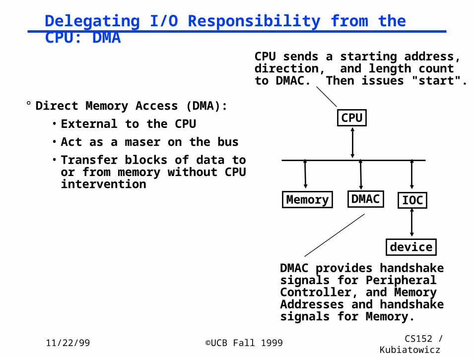
Delegating I/O Responsibility from the CPU: DMA
° Direct Memory Access (DMA):
• External to the CPU
• Act as a maser on the bus
• Transfer blocks of data to or from memory without CPU intervention
CPU
IOC
device
Memory DMAC
CPU sends a starting address, direction, and length count to DMAC. Then issues "start".
DMAC provides handshakesignals for PeripheralController, and MemoryAddresses and handshakesignals for Memory.

11/22/99 ©UCB Fall 1999 CS152 / Kubiatowicz
Lec23.62
Delegating I/O Responsibility from the CPU: IOP
CPU IOP
Mem
D1
D2
Dn
. . .main memory
bus
I/Obus
CPU
IOP
(1) Issuesinstructionto IOP
memory
(2)
(3)
Device to/from memorytransfers are controlledby the IOP directly.
IOP steals memory cycles.
OP Device Address
target devicewhere cmnds are
IOP looks in memory for commands
OP Addr Cnt Other
whatto do
whereto putdata
howmuch
specialrequests
(4) IOP interrupts CPU when done
11/22/99 ©UCB Fall 1999 CS152 / Kubiatowicz
Lec23.63
Responsibilities of the Operating System
° The operating system acts as the interface between:
• The I/O hardware and the program that requests I/O
° Three characteristics of the I/O systems:
• The I/O system is shared by multiple program using the processor
• I/O systems often use interrupts (external generated exceptions) to communicate information about I/O operations.
- Interrupts must be handled by the OS because they cause a transfer to supervisor mode
• The low-level control of an I/O device is complex:
- Managing a set of concurrent events
- The requirements for correct device control are very detailed

11/22/99 ©UCB Fall 1999 CS152 / Kubiatowicz
Lec23.64
Operating System Requirements
° Provide protection to shared I/O resources
• Guarantees that a user’s program can only access theportions of an I/O device to which the user has rights
° Provides abstraction for accessing devices:
• Supply routines that handle low-level device operation
° Handles the interrupts generated by I/O devices
° Provide equitable access to the shared I/O resources
• All user programs must have equal access to the I/O resources
° Schedule accesses in order to enhance system throughput

11/22/99 ©UCB Fall 1999 CS152 / Kubiatowicz
Lec23.65
OS and I/O Systems Communication Requirements
° The Operating System must be able to prevent:
• The user program from communicating with the I/O device directly
° If user programs could perform I/O directly:
• Protection to the shared I/O resources could not be provided
° Three types of communication are required:
• The OS must be able to give commands to the I/O devices
• The I/O device must be able to notify the OS when the I/O device has completed an operation or has encountered an error
• Data must be transferred between memory and an I/O device

11/22/99 ©UCB Fall 1999 CS152 / Kubiatowicz
Lec23.66
Multimedia Bandwidth Requirements
° High Quality Video
• Digital Data = (30 frames / second) (640 x 480 pels) (24-bit color / pel) = 221 Mbps (75 MB/s)
° Reduced Quality Video
• Digital Data = (15 frames / second) (320 x 240 pels) (16-bit color / pel) = 18 Mbps (2.2 MB/s)
° High Quality Audio
• Digital Data = (44,100 audio samples / sec) (16-bit audio samples)
• (2 audio channels for stereo) = 1.4 Mbps
° Reduced Quality Audio
• Digital Data = (11,050 audio samples / sec) (8-bit audio samples) (1 audio channel for monaural) = 0.1 Mbps
° compression changes the whole story!

11/22/99 ©UCB Fall 1999 CS152 / Kubiatowicz
Lec23.67
Multimedia and Latency
° How sensitive is your eye / ear to variations in audio / video rate?
° How can you ensure constant rate of delivery?
° Jitter (latency) bounds vs constant bit rate transfer
° Synchronizing audio and video streams
• you can tolerate 15-20 ms early to 30-40 ms late

11/22/99 ©UCB Fall 1999 CS152 / Kubiatowicz
Lec23.68
P1394 High-Speed Serial Bus (firewire)
° a digital interface – there is no need to convert digital data into analog and tolerate a loss of data integrity,
° physically small - the thin serial cable can replace larger and more expensive interfaces,
° easy to use - no need for terminators, device IDs, or elaborate setup,
° hot pluggable - users can add or remove 1394 devices with the bus active,
° inexpensive - priced for consumer products,
° scalable architecture - may mix 100, 200, and 400 Mbps devices on a bus,
° flexible topology - support of daisy chaining and branching for true peer-to-peer communication,
° fast - even multimedia data can be guaranteed its bandwidth for just-in-time delivery, and
° non-proprietary
° mixed asynchronous and isochornous traffic

11/22/99 ©UCB Fall 1999 CS152 / Kubiatowicz
Lec23.69
isochronouschannel #1time slot
Firewire Operations
° Fixed frame is divided into preallocated CBR slots + best effort asycnhronous slot
° Each slot has packet containing “ID” command and data
° Example: digital video camera can expect to send one 64 byte packet every 125 µs
• 80 * 1024 * 64 = 5MB/s
Packet Frame = 125 µsecs
isochronouschannel #1time slot
Time slot available for asynchronous transport
Timing indicator

11/22/99 ©UCB Fall 1999 CS152 / Kubiatowicz
Lec23.70
Summary:
° I/O performance limited by weakest link in chain between OS and device
° Queueing theory is important
• 100% utilization means very large latency
• Remember, for M/G/1 queue:
- queue size goes as u/(1-u)
- latency goes as Tser×u/(1-u)
° Disk I/O Benchmarks: I/O rate vs. Data rate vs. latency
° Three Components of Disk Access Time:
• Seek Time: advertised to be 8 to 12 ms. May be lower in real life.
• Rotational Latency: 4.1 ms at 7200 RPM and 8.3 ms at 3600 RPM
• Transfer Time: 2 to 12 MB per second
° I/O device notifying the operating system:
• Polling: it can waste a lot of processor time
• I/O interrupt: similar to exception except it is asynchronous
° Delegating I/O responsibility from the CPU: DMA, or even IOP
° wide range of devices
• multimedia and high speed networking poise important challenges