cs110 electric field meter instruction manual electric field meter 1. general description 1.1 cs110...
TRANSCRIPT

CS110 Electric Field MeterRevision: 4/12
C o p y r i g h t © 2 0 0 5 - 2 0 1 2C a m p b e l l S c i e n t i f i c , I n c .


PLEASE READ FIRST About this manual Please note that this manual was originally produced by Campbell Scientific Inc. (CSI) primarily for the US market. Some spellings, weights and measures may reflect this origin. Some useful conversion factors:
Area: 1 in2 (square inch) = 645 mm2 Length: 1 in. (inch) = 25.4 mm 1 ft (foot) = 304.8 mm 1 yard = 0.914 m 1 mile = 1.609 km Mass: 1 oz. (ounce) = 28.35 g 1 lb (pound weight) = 0.454 kg Pressure: 1 psi (lb/in2) = 68.95 mb Volume: 1 US gallon = 3.785 litres
In addition, part ordering numbers may vary. For example, the CABLE5CBL is a CSI part number and known as a FIN5COND at Campbell Scientific Canada (CSC). CSC Technical Support will be pleased to assist with any questions.

CS110 Table of Contents PDF viewers: These page numbers refer to the printed version of this document. Use the PDF reader bookmarks tab for links to specific sections.
1. General Description.....................................................1 1.1 CS110 Introduction...................................................................................1 1.2 CR1000 Datalogger ..................................................................................2 1.3 Meteorological Inputs...............................................................................2 1.4 Communication and Data Storage ............................................................2 1.5 Digital I/O.................................................................................................3 1.6 Self-Check Features..................................................................................3
2. CS110 Specifications ..................................................4
3. CS110 Measurement Details.......................................7
4. Site Requirements and Recommendations...............9 4.1 Power Requirements.................................................................................9 4.2 Campbell Scientific, Inc. Power Supplies ..............................................10 4.3 Communication Options .........................................................................10 4.4 Site Recommendations ...........................................................................11
5. Factory Calibration and Site Correction ..................11 5.1 Factory Calibration .................................................................................11 5.2 Site Correction........................................................................................14
6. Lightning Warning .....................................................19
7. CRBasic Programming..............................................21
8. CS110 Measurement Instructions ............................25 8.1 CR1000 Measurement Overview............................................................25 8.2 Measuring Electric Field.........................................................................27 8.3 Measuring Electric Field Change ...........................................................27 8.4 Measuring Solar Radiation or Barometric Pressure................................27 8.5 Measuring Air Temperature and Relative Humidity ..............................28 8.6 Measuring Wind Speed and Direction....................................................28 8.7 Measuring Rainfall .................................................................................29 8.8 Measuring Internal Case Humidity.........................................................29
9. PC Software................................................................29 9.1 Quick Start ..............................................................................................29
i
CS110 Table of Contents
10. Maintenance .............................................................33 10.1 Checking Site Ground Integrity ........................................................... 33 10.2 Corrosion and Rust Inhibitors .............................................................. 33 10.3 Self-Check Features ............................................................................. 35 10.4 Cleaning the CS110 Electrode Head.................................................... 36 10.5 Changing Desiccant ............................................................................. 37 10.6 Checking Shutter/Encoder Alignment ................................................. 39 10.7 Re-Calibration...................................................................................... 40
11. References................................................................40
Appendices
A. CS110 Measurement Status Codes .......................A-1
B. CS110 Accessories .................................................B-1 B.1 Zero Field Cover Plate ........................................................................ B-1 B.2 Upward-Facing Site Calibration Kit.................................................... B-1 B.3 CR1000 Keyboard Display ................................................................. B-1 B.4 Miscellaneous Peripheral Modules...................................................... B-1
C. CS110 Connector Pin-outs .....................................C-1
D. Servicing the CS110 ................................................D-1 D.1 Lid Gasket ........................................................................................... D-1 D.2 Changing Out the CR1000.................................................................. D-1 D.3 Changing Out Motor Assembly .......................................................... D-2 D.4 Changing Out the CS110 Panel Board Assembly............................... D-2 D.5 Shutter/Encoder Alignment................................................................. D-3 D.6 Motor O-ring Seal ............................................................................... D-6
E. CS110 as a Slow Antenna .......................................E-1 E.1 Response of the CS110 Slow Antenna in the Frequency Domain .......E-1 E.2 Response of the CS110 Slow Antenna in the Time Domain................E-3 E.3 Programming ........................................................................................E-5 E.4 Calibration ............................................................................................E-6
F. Example CRBasic Programs .................................. F-1
G. CS110 2 Meter CM10 Tripod Site ...........................G-1
ii
CS110 Table of Contents
H. Tripod CS110 and StrikeGuard Site....................... H-1 H.1 Tripod CS110 and StrikeGuard .......................................................... H-1
H.1.1 Installation of the Tripod CS110 and StrikeGuard site ............. H-2 H.1.2 Determination of Csite .............................................................. H-7
Figures 1. CS110 Electric Field Meter ........................................................................1 2. Charge amplifier circuitry of reciprocating electric field meter .................7 3. Charge amplifier output during an electric field measurement cycle .........8 4. CS110 average current consumption versus measurement interval..........10 5. Parallel-plate electric field meter calibration chamber ..............................12 6. Factory calibration data for CS110 SN: 1026...........................................13 7. NIST calibration certificate ......................................................................14 8. CS110 2 Meter CM10 Tripod Site............................................................15 9. Campbell Scientific, Inc. electric field meter site correction facility........16 10. CS110 attached to upward-facing flush-mounted plate for site
correction ...........................................................................................17 11. Site correction data for CS110 2 Meter CM10 Tripod Site ....................18 12. Electric field measured with CS110 during local thunderstorm.............20 13. CS110 stator, shutter and sense electrode...............................................36 14. Inside of CS110 case illustrating bracket for holding desiccant.............38 D-1. Exploded View of CS110 Electric Field Meter................................. D-1 D-2. CS110 Motor Assembly .................................................................... D-5 E-1. CS110 slow antenna frequency response............................................E-2 E-2. KSC electric field and CS110 slow antenna data................................E-3 E-3. KSC electric field change and CS110 slow antenna data ...................E-4 G-1. CS110 2 Meter CM10 Tripod Site .................................................... G-1 G-2. CS110 on CM10 Tripod Mast ........................................................... G-3 G-3. Earth Grounding ................................................................................ G-4 G-4. Determination of Csite ...................................................................... G-5 H-1. Tripod CS110 and StrikeGuard ......................................................... H-1 H-2. CS110 and StrikeGuard on Tripod Mast ........................................... H-3 H-3. Grounding the CS110 Grounding Strap ............................................ H-4 H-4. Grounding the Tripod and Battery .................................................... H-5 H-5. Connections for Combined System ................................................... H-6 H-6. Determination of Csite ...................................................................... H-7
iii

CS110 Table of Contents
iv
CS110 Electric Field Meter
1. General Description 1.1 CS110 Introduction
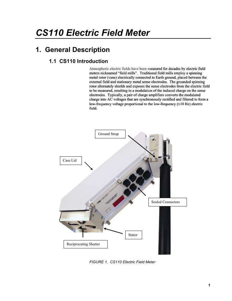
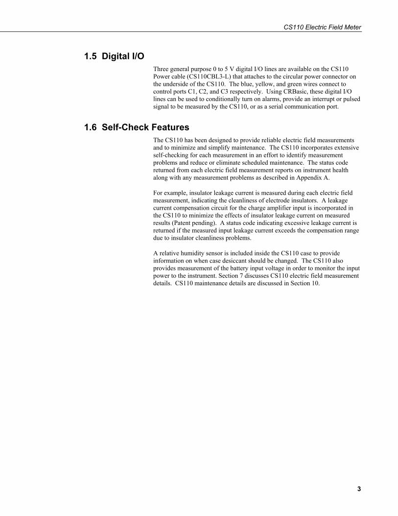
Atmospheric electric fields have been measured for decades by electric field meters nicknamed “field mills”. Traditional field mills employ a spinning metal rotor (vane) electrically connected to Earth ground, placed between the external field and stationary metal sense electrodes. The grounded spinning rotor alternately shields and exposes the sense electrodes from the electric field to be measured, resulting in a modulation of the induced charge on the sense electrodes. Typically, a pair of charge amplifiers converts the modulated charge into AC voltages that are synchronously rectified and filtered to form a low-frequency voltage proportional to the low-frequency (≤10 Hz) electric field.
easured for decades by electric field meters nicknamed “field mills”. Traditional field mills employ a spinning metal rotor (vane) electrically connected to Earth ground, placed between the external field and stationary metal sense electrodes. The grounded spinning rotor alternately shields and exposes the sense electrodes from the electric field to be measured, resulting in a modulation of the induced charge on the sense electrodes. Typically, a pair of charge amplifiers converts the modulated charge into AC voltages that are synchronously rectified and filtered to form a low-frequency voltage proportional to the low-frequency (≤10 Hz) electric field.
Ground Strap
Case Lid
Sealed Connectors
Stator
Reciprocating Shutter
FIGURE 1. CS110 Electric Field Meter
1

CS110 Electric Field Meter
Unlike traditional rotating vane field mills, the CS110 uses a reciprocating shutter. A stepper motor opens and then closes the reciprocating shutter by 45° during measurements. The reciprocating shutter is electrically connected to ground potential by a flexible stainless-steel strap operated below its fatigue limit, resulting in an ultra-reliable electrical ground connection. The CS110 offers improved dc error performance, as compared with traditional rotating vane field mills, by utilizing a zero field (closed shutter) reference for each measurement. Power consumption is also reduced (< 1 Watt for 1 measurement per second) in the CS110 by de-energizing the motor coils in between measurements.
1.2 CR1000 Datalogger The CS110 contains an embedded CR1000 datalogger, which provides measurement and control functions, data processing and storage, a user interface language (CRBasic™), and flexible communications options. LoggerNet™ PC software (purchased separately) provides versatile networking and data collection capabilities. For more details on the CR1000 datalogger see the CR1000 Measurement and Control System Operator’s Manual.
1.3 Meteorological Inputs The CS110 interfaces to various meteorological sensors resulting in an automated weather station that includes atmospheric electric field. Wind speed and direction, air temperature and relative humidity, rainfall, solar radiation or barometric pressure sensors interface directly to the CS110. Measurement details of the various sensors are given in section 7.
1.4 Communication and Data Storage The circular RS-232 connector on the underside of the CS110 can be used to interface directly to RS-232 devices (DTE or DCE), utilizing the CS110 RS-232 cable (CS110CBL1-L).
The circular CS I/O connector on the underside of the CS110 can be used to interface directly to various Campbell Scientific, Inc. peripherals, utilizing the CS110 CS I/O cable (CS110CBL2-L). Examples of CS I/O peripherals include the CR1000 Keyboard Display and the COM220 phone modem.
The DB9 end of CS110 RS-232 cable and CS110 CS I/O cable won’t fit through the conduit used on some enclosures, whereas the smaller circular end that connects to the CS110 will.
The embedded CR1000 will have either 2 MB (PN: 18292) or 4 MB (PN: 18293) of battery-backed SRAM and 16K Flash EEPROM. The operating system and user programs are stored in Flash EEPROM. Memory not used by the operating system and user program is available for data storage. The size of available memory can be seen in the Status Table discussed in Appendix B of the CR1000 manual.
2
CS110 Electric Field Meter
1.5 Digital I/O Three general purpose 0 to 5 V digital I/O lines are available on the CS110 Power cable (CS110CBL3-L) that attaches to the circular power connector on the underside of the CS110. The blue, yellow, and green wires connect to control ports C1, C2, and C3 respectively. Using CRBasic, these digital I/O lines can be used to conditionally turn on alarms, provide an interrupt or pulsed signal to be measured by the CS110, or as a serial communication port.
1.6 Self-Check Features The CS110 has been designed to provide reliable electric field measurements and to minimize and simplify maintenance. The CS110 incorporates extensive self-checking for each measurement in an effort to identify measurement problems and reduce or eliminate scheduled maintenance. The status code returned from each electric field measurement reports on instrument health along with any measurement problems as described in Appendix A.
For example, insulator leakage current is measured during each electric field measurement, indicating the cleanliness of electrode insulators. A leakage current compensation circuit for the charge amplifier input is incorporated in the CS110 to minimize the effects of insulator leakage current on measured results (Patent pending). A status code indicating excessive leakage current is returned if the measured input leakage current exceeds the compensation range due to insulator cleanliness problems.
A relative humidity sensor is included inside the CS110 case to provide information on when case desiccant should be changed. The CS110 also provides measurement of the battery input voltage in order to monitor the input power to the instrument. Section 7 discusses CS110 electric field measurement details. CS110 maintenance details are discussed in Section 10.
3

CS110 Electric Field Meter
2. CS110 Specifications Electric Field Measurement Performance:
Parallel-Plate Configuration
Accuracy ±1% of reading + 60 V m-1 offset1
Measurement Range3 (V m-1)
Resolution(V m-1)
Sensitivity(µV/V m-
1)
Noise (V m-1 RMS)
±(0 to 21,000) 3 12 4.0
±(21,000 to 212,000) 30 118 18.0
2 m CM10 Tripod Configuration2
Accuracy ±5% of reading + 8 V m-1 offset1
Measurement Range3 (V m-1)
Resolution(V m-1)
Sensitivity(µV/V m-
1)
Noise (V m-1 RMS)
±(0 to 2,200) 0.32 1.2 0.42
±(2,200 to 22,300) 3.2 13 1.9
1Typical offset for clean electrodes is ≤ |30 V m-1| for the parallel-plate configuration, which is reduced by the field enhancement factor for typical inverted and elevated mounting configurations.
2Field enhancement due to typical inverted and elevated mounting requires additional site correction, estimated at ±5% accuracy when done in appropriate high field conditions. Practical outdoor CS110 electric field measurement accuracy is estimated at ±5% of reading + 8 V m-1 for the CS110 2 Meter CM10 Tripod Site.
3The CS110 incorporates automatic gain ranging between two input ranges. The measurement is first tried on the lowest input range. If the signal is too large for the lowest range, the larger range is used.
Standard Mounting: 2 m height on a CM10 tripod mast
Site Correction: Site correction factors available for several standard mounting configurations
4
CS110 Electric Field Meter
Sample (Measurement) Rate: Programmable sample rate up to 5 samples per
second, variable sample rates possible. Variable example: sample every 10 seconds until field exceeds threshold then sample once a second until field returns to normal.
Power Requirements: 11 to 16 Vdc; peak-current demand is 750 mA during motor operation.
7 mA @ 12 V = 0.08 W average power consumption at 1 sample per 10 seconds
60 mA @ 12 V = 0.7 W average power consumption at 1 sample per second
120 mA @ 12 V = 1.4 W average power consumption at 2 samples per second
300 mA @ 12 V = 3.6 W average power consumption at 5 samples per second
Communication: 1 RS-232 port; 1 CS I/O port used to interface with our peripherals such as a COM320 Voice Modem; digital control ports 1, 2, and 3 for alarm, SDI-12 communications, or asynchronous communications
Baud Rates: Selectable from 300 to 115,200 bps
ASCII Protocol: One start bit, one stop bit, eight data bits, no parity
Lightning Protection: Multi-stage transient protection on all extenal interfaces
CE Compliance: Standards to which conformity is declared—BS EN61326:2002
Connectors/ Compatible Sensors: Connector Label Compatible Sensors1
Temp/RH: HC2S3-L, HMP60-L (choose the -C cable termination option for these sensors)
Wind: 05103-LC, 05106-LC, 05305-LC, 034B-LC, 03001-LC
Solar: LI200X-LC pyranometer, CS100 barometer or CS106 barometer (the barometer attaches to the CS110 via the 17640 cable; they must be housed in a separate enclosure such as the ENC100)
Rain: CS700-LC, TB4-LC, TE525-LC, TE525WS-LC, TE525MM-LC
1 One sensor per connector
Programmability: CRBasicTM programming allows the selection of sample rate, data processing and storage options and setting output ports based on alarm conditions. LoggerNetTM includes the CRBasic editor and compiler.
5
CS110 Electric Field Meter
Rugged Construction: Ultra-reliable metallic ground connection to reciprocating shutter (no wiping contact), brushless stepper motor, powder-coated aluminum case, Teflon insulators, and electro-polished 316L stainless steel used for corrosion protection of critical exposed metallic parts
Easy Maintenance: The stator is easily removed for cleaning (proper cleaning does not invalidate calibration). Instrument self-checking allows maintenance to be performed on an as needed basis. The self-checking also monitors internal humidity, insulator cleanliness, and power supply voltage, and verifies that CS110 components such as the charge amplifier and shutter open/close are functioning properly.
Operating Temperature Range: -25° to 50°C standard, -40° to +85°C optional
RH Range: 0 to 100% RH
Dimensions: 15.2 x 15.2 x 43.2 cm (6 x 6 x 17 in)
Mounting: Vertical pipe 1.91 to 6.35 cm OD (0.75 to 2.5 in)
Weight: 4 kg (9 lb)
6

CS110 Electric Field Meter
3. CS110 Measurement Details The charge amplifier circuitry of the reciprocating electric field meter is depicted in Figure 2. Induced charge on the sense electrode results in the operational amplifier placing charge on the feedback capacitor C in order to restore the sense electrode to virtual ground.
FIGURE 2. Charge amplifier circuitry of reciprocating electric field meter
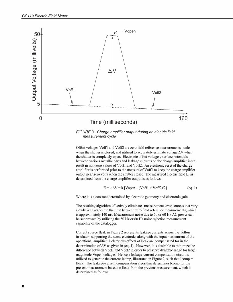
The charge amplifier output during a measurement cycle of the reciprocating electric field meter is illustrated in Figure 3.
7
CS110 Electric Field Meter
160
FIGURE 3. Charge amplifier output during an electric field measurement cycle
Offset voltages Voff1 and Voff2 are zero field reference measurements made when the shutter is closed, and utilized to accurately estimate voltage ΔV when the shutter is completely open. Electronic offset voltages, surface potentials between various metallic parts and leakage currents on the charge amplifier input result in non-zero values of Voff1 and Voff2. An electronic reset of the charge amplifier is performed prior to the measure of Voff1 to keep the charge amplifier output near zero volts when the shutter closed. The measured electric field E, as determined from the charge amplifier output is as follows:
E = k⋅ΔV = k⋅[Vopen – (Voff1 + Voff2)/2] (eq. 1)
Where k is a constant determined by electrode geometry and electronic gain.
The resulting algorithm effectively eliminates measurement error sources that vary slowly with respect to the time between zero field reference measurements, which is approximately 140 ms. Measurement noise due to 50 or 60 Hz AC power can be suppressed by utilizing the 50 Hz or 60 Hz noise rejection measurement capability of the datalogger.
Current source Ileak in Figure 2 represents leakage currents across the Teflon insulators supporting the sense electrode, along with the input bias current of the operational amplifier. Deleterious effects of Ileak are compensated for in the determination of ΔV as given in (eq. 1). However, it is desirable to minimize the difference between Voff1 and Voff2 in order to preserve dynamic range for large magnitude Vopen voltages. Hence a leakage-current compensation circuit is utilized to generate the current Icomp, illustrated in Figure 2, such that Icomp = Ileak. The leakage-current compensation algorithm determines Icomp for the present measurement based on Ileak from the previous measurement, which is determined as follows:
8

CS110 Electric Field Meter
Ileak = Cf·(Voff1 – Voff2)/ΔT + Icomp (eq. 2)
Where Cf is the value of feedback capacitor used in the charge amplifier, and Icomp is the leakage current compensation value implemented during the measurement.
This charge amplifier input leakage current increases with degradation of insulation of the sense electrode insulators due to moisture or other surface contamination. Consequently, the measurement and reporting of Ileak is useful in determining if or when insulators should be cleaned.
The reciprocating motion of the CS110 electric field meter is limited to approximately 5 Hz, which is adequate for lightning hazard warning, where 1 minute averaged data is often used. For applications desiring > 5 Hz, the CS110 reciprocating electric field meter can be configured as a slow antenna (MacGorman and Rust 1998). The shutter would typically be left open indefinitely in slow antenna mode and resistor R3, depicted in Figure 2, is switched in parallel with Cf providing a 66 ms decay time constant for the charge amplifier. In the slow antenna mode, the charge amplifier has a high-pass filter frequency response with the lower cutoff frequency defined as f3dB = (2⋅π⋅R⋅C)-1 = 2.4 Hz. In this mode the instrument is a field change meter and the charge amplifier output can be sampled by the datalogger as fast as every 20 ms (50 Hz), using 250 μs integration durations for the analog integrator. Voltage measurements using the 250 μs integration duration for an analog integrator, result in an upper 3 dB bandwidth of 1.8 kHz. Detailed information regarding the slow antenna mode of the CS110 is given in Appendix E and Section 8.3.
4. Site Requirements and Recommendations 4.1 Power Requirements
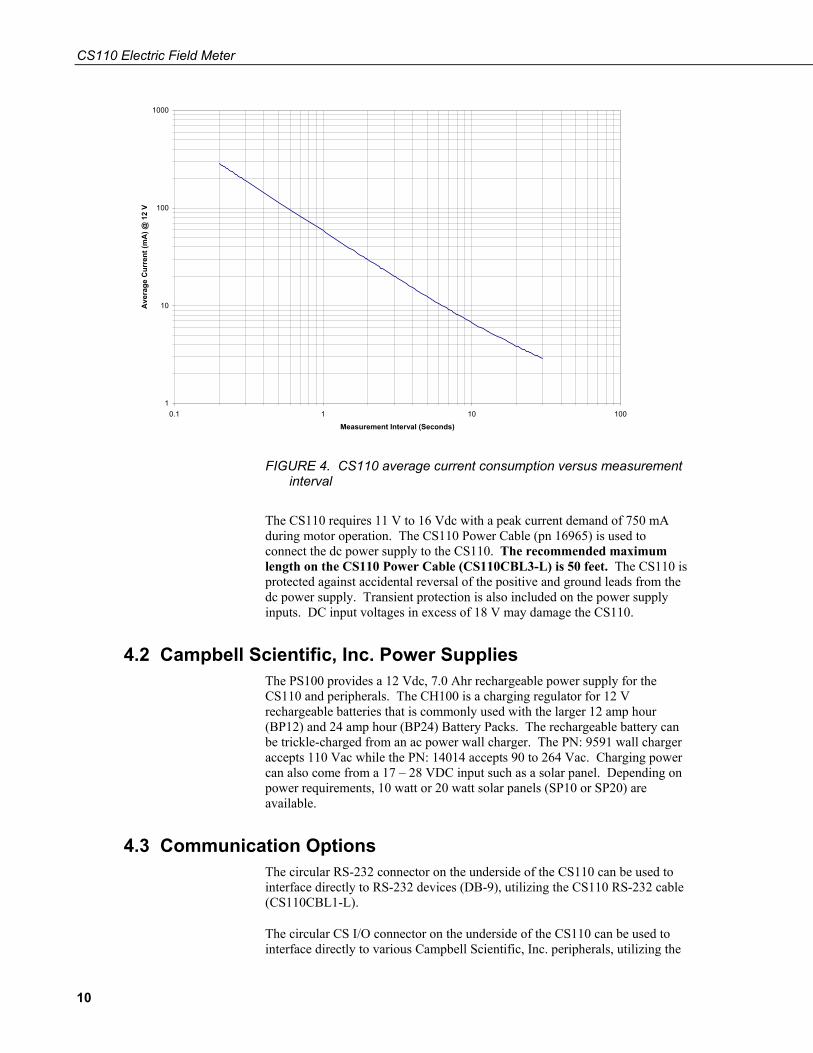
Field mills typically consume many watts of power because their motors are operated continuously. In the reciprocating approach, the stepper motor is powered off much of the time, resulting in low power consumption. The current required by the CS110 powered from 12 V DC is shown in Figure 4. As depicted in the figure, the average electric field meter current is a function of the desired measurement rate, which is user-controlled by means of the datalogger program, making economical remote solar power feasible. Variable sample rates based on measured results can also be implemented to conserve power in solar powered applications. For example, the datalogger can be programmed to measure electric field at a 10-second rate during fair weather conditions, and then automatically switch to 1-second measurements during threatening conditions. An example variable sample rate program is given in Appendix F. Figure 4 does not include the current required for peripheral devices necessary to communicate with the CS110 site. Like the stepper motor, communication devices that are turned off when not needed, can offer low average power consumption.
9
CS110 Electric Field Meter
1
10
100
1000
0.1 1 10 100
Measurement Interval (Seconds)
Ave
rage
Cur
rent
(mA
) @ 1
2 V
FIGURE 4. CS110 average current consumption versus measurement interval
The CS110 requires 11 V to 16 Vdc with a peak current demand of 750 mA during motor operation. The CS110 Power Cable (pn 16965) is used to connect the dc power supply to the CS110. The recommended maximum length on the CS110 Power Cable (CS110CBL3-L) is 50 feet. The CS110 is protected against accidental reversal of the positive and ground leads from the dc power supply. Transient protection is also included on the power supply inputs. DC input voltages in excess of 18 V may damage the CS110.
4.2 Campbell Scientific, Inc. Power Supplies The PS100 provides a 12 Vdc, 7.0 Ahr rechargeable power supply for the CS110 and peripherals. The CH100 is a charging regulator for 12 V rechargeable batteries that is commonly used with the larger 12 amp hour (BP12) and 24 amp hour (BP24) Battery Packs. The rechargeable battery can be trickle-charged from an ac power wall charger. The PN: 9591 wall charger accepts 110 Vac while the PN: 14014 accepts 90 to 264 Vac. Charging power can also come from a 17 – 28 VDC input such as a solar panel. Depending on power requirements, 10 watt or 20 watt solar panels (SP10 or SP20) are available.
4.3 Communication Options The circular RS-232 connector on the underside of the CS110 can be used to interface directly to RS-232 devices (DB-9), utilizing the CS110 RS-232 cable (CS110CBL1-L).
The circular CS I/O connector on the underside of the CS110 can be used to interface directly to various Campbell Scientific, Inc. peripherals, utilizing the
10

CS110 Electric Field Meter
CS110 CS I/O cable (CS110CBL2-L). Examples of CS I/O peripherals include the CR1000 Keyboard Display and the COM220 phone modem.
The CS110 also offers SDI-12 communication or SDM (Synchronous Device for Measurement) control capability utilizing the CR1000 control ports available through the CS110 POWER CABLE (CS110CBL3-L).
4.4 Site Recommendations Many factors can distort and/or change the electric field at a given sight. For example, vegetation growth can reduce the effective height of an elevated instrument above the ground and can created unwanted space-charge due to corona discharge. Gravel rings or concrete pads around a given site are recommended to prevent changes in effective instrument height due to vegetation growth. Electric field meters used for lightning warning at Kennedy Space Center use a 25-foot radius gravel ring around each electric field meter [LPLWS].
Animals and people within the vicinity of an electric field meter can significantly alter the measurements. Fencing off a given site may be best for some applications. However, installing a small metal fence around an electric field meter site may result in corruption of measurements at large electric fields because of corona discharge from sharp metal points on the fence.
Aerosols, dust, and automobile exhaust should be considered when selecting an electric field meter site, as they can affect the local electric field.
In theory, the effects of tall nearby objects can be accounted for in site correction. Yet, because of possible corona current along with general field distortion, it is recommended that electric field meter sites should not be located near tall objects. Kennedy Space Center site requirements stipulate having no objects protruding higher than 18° above the horizon, as seen from the ground at the electric field meter location [LPLWS]. Roof mounted electric field measurements are practical if a site correction can be done to account for field distortions.
Also a good Earth ground connection to the CS110 and associated mounting hardware is necessary to make a given site appear as a vertical extension of the Earth ground. It is recommended that the integrity of this Earth Ground connection be checked periodically by verifying that the resistance of the stator to Earth Ground rod is <1 Ω.
Although the list of factors that can impair electric field measurements is long, experience has shown that useful electric field measurements can be made by paying careful attention to the above mentioned details.
5. Factory Calibration and Site Correction 5.1 Factory Calibration
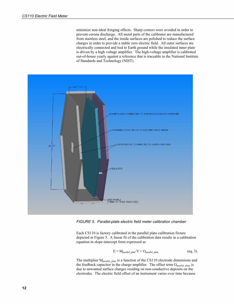
Electric field meters are typically factory calibrated using a parallel plate method, where a uniform electric field is developed by applying a known voltage between parallel conductive plates. The large hexagonal parallel plate electric field calibrator illustrated in Figure 5 is used for factory calibration of the CS110 Electric Field Meter. The large physical size was incorporated to
11
CS110 Electric Field Meter
minimize non-ideal fringing effects. Sharp corners were avoided in order to prevent corona discharge. All metal parts of the calibrator are manufactured from stainless steel, and the inside surfaces are polished to reduce the surface charges in order to provide a stable zero electric field. All outer surfaces are electrically connected and tied to Earth ground while the insulated inner plate is driven by a high voltage amplifier. The high-voltage amplifier is calibrated out-of-house yearly against a reference that is traceable to the National Institute of Standards and Technology (NIST).
FIGURE 5. Parallel-plate electric field meter calibration chamber
Each CS110 is factory calibrated in the parallel plate calibration fixture depicted in Figure 5. A linear fit of the calibration data results in a calibration equation in slope-intercept form expressed as
E = Mparallel_plate⋅V + Oparallel_plate (eq. 3).
The multiplier Mparallel_plate is a function of the CS110 electrode dimensions and the feedback capacitor in the charge amplifier. The offset term Oparallel_plate is due to unwanted surface charges residing on non-conductive deposits on the electrodes. The electric field offset of an instrument varies over time because
12

CS110 Electric Field Meter
of variations in surface cleanliness along with charging and discharging processes. Polished 316-L stainless-steel is used for critical electrode surfaces on the CS110 to minimize unwanted surface charges. CS110s with clean electrodes have been found to display electric field offsets <⏐30 V/m⏐, which has negligible effect on the determination of Mparallel_plate because of the ±15 kV/m range of electric fields used during factory calibration. Neglecting Oparallel_plate results in the simplified parallel-plate calibration equation
E = Mparallel_plate⋅V (eq. 4).
The estimated measurement accuracy of Mparallel_plate for the CS110 calibrated in the parallel plate electric field calibrator illustrated in Figure 5 is ± 1 %. The electric field offset of the CS110 can be measured by covering the stator with a clean Zero Electric Field Cover (PN: 17642). If the resulting zero field reading with the zero field cover exceeds an absolute value of 60 V/m then cleaning of electrodes in the CS110 is suggested. The factory calibration data for a typical CS110 factory calibration and resulting determination of Mparallel_plate = 84.32 V/m⋅mV (Volts/meter⋅millivolt) is illustrated in Figure 6.
y = 84.324x + 26.258R2 = 1
-15000
-10000
-5000
0
5000
10000
15000
20000
-200 -150 -100 -50 0 50 100 150 200 250
App
lied
Elec
tric
Fie
ld (V
/m)
-20000
Charge Amplifier Output Voltage (mV)
FIGURE 6. Factory calibration data for CS110 SN: 1026
13

CS110 Electric Field Meter
FIGURE 7. NIST calibration certificate
Careful removal and replacement of the stator on the CS110 does not invalidate the factory derived Mparallel_plate of a given unit. However, switching stators with another unit or accidentally bending the stator, shutter or sense electrodes invalidates the factory parallel-plate calibration because of possible electrode dimensional changes.
NOTE
5.2 Site Correction As previously mentioned, each CS110 is factory calibrated in a parallel plate calibration fixture resulting in calibration equation 4. However, when monitoring the Earth’s electric field, equation 4 is valid only if the instrument aperture is mounted flush with the Earth’s surface and upward-facing. Yet for permanent outdoor measurements of electric field, a flush-mounted and upward-facing orientation is problematic because of dirt, bird droppings, rain, etc., collecting on the sense electrodes and fouling the measurement.
14
CS110 Electric Field Meter
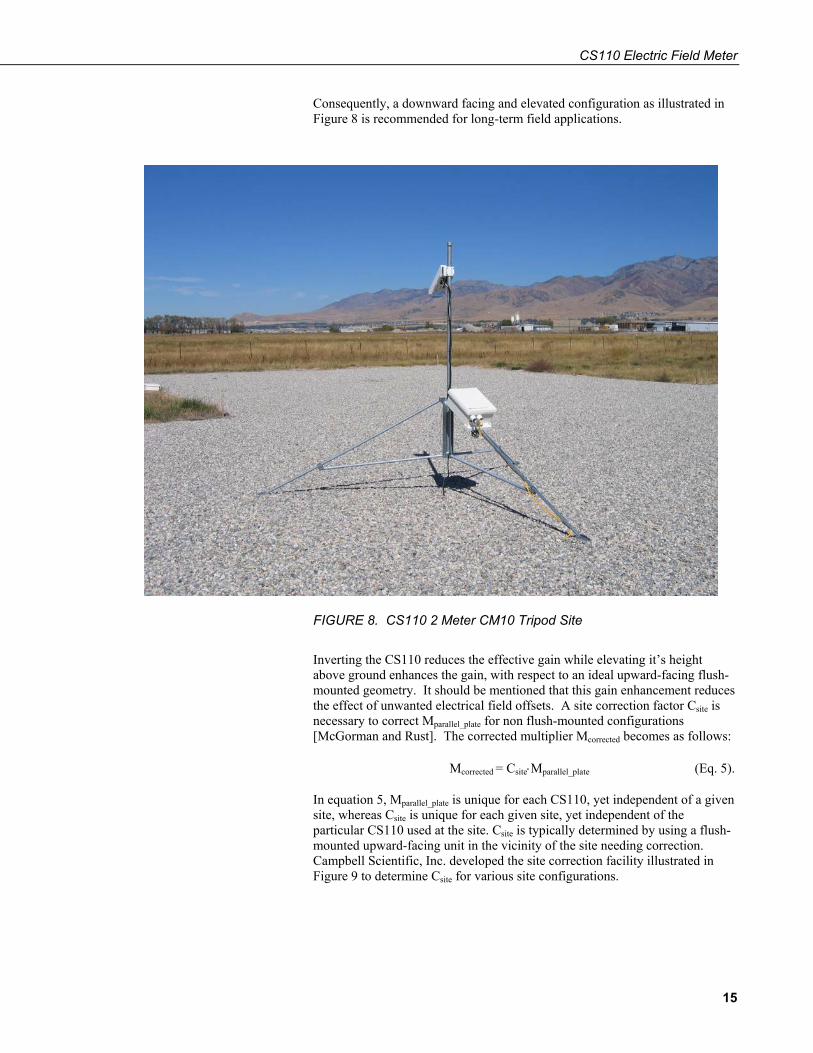
Consequently, a downward facing and elevated configuration as illustrated in Figure 8 is recommended for long-term field applications.
FIGURE 8. CS110 2 Meter CM10 Tripod Site
Inverting the CS110 reduces the effective gain while elevating it’s height above ground enhances the gain, with respect to an ideal upward-facing flush-mounted geometry. It should be mentioned that this gain enhancement reduces the effect of unwanted electrical field offsets. A site correction factor Csite is necessary to correct Mparallel_plate for non flush-mounted configurations [McGorman and Rust]. The corrected multiplier Mcorrected becomes as follows:
Mcorrected = Csite⋅Mparallel_plate (Eq. 5).
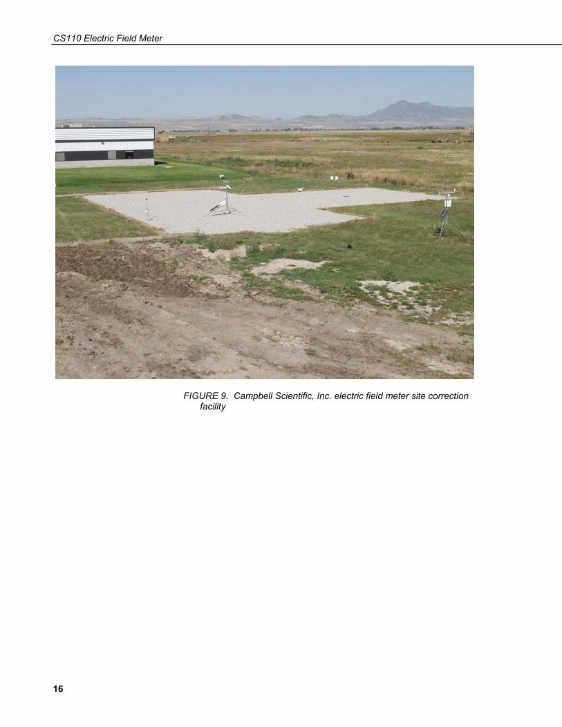
In equation 5, Mparallel_plate is unique for each CS110, yet independent of a given site, whereas Csite is unique for each given site, yet independent of the particular CS110 used at the site. Csite is typically determined by using a flush-mounted upward-facing unit in the vicinity of the site needing correction. Campbell Scientific, Inc. developed the site correction facility illustrated in Figure 9 to determine Csite for various site configurations.
15
CS110 Electric Field Meter
FIGURE 9. Campbell Scientific, Inc. electric field meter site correction facility
16
CS110 Electric Field Meter
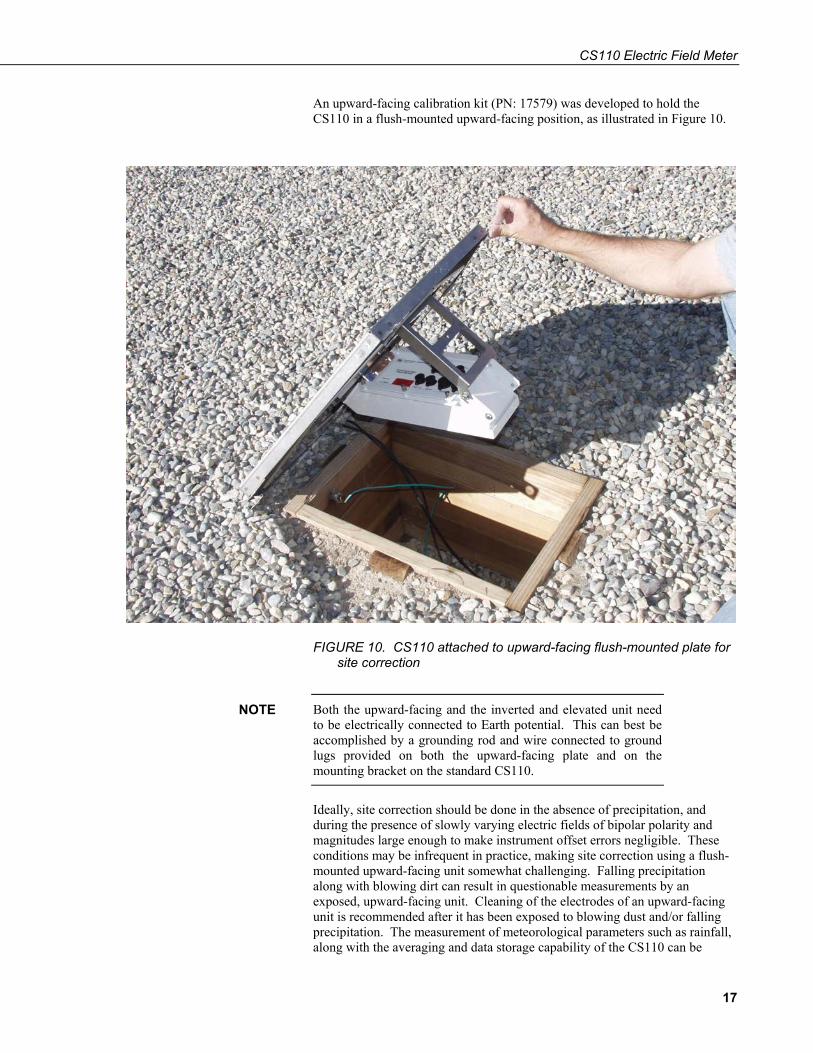
An upward-facing calibration kit (PN: 17579) was developed to hold the CS110 in a flush-mounted upward-facing position, as illustrated in Figure 10.
FIGURE 10. CS110 attached to upward-facing flush-mounted plate for site correction
Both the upward-facing and the inverted and elevated unit need to be electrically connected to Earth potential. This can best be accomplished by a grounding rod and wire connected to ground lugs provided on both the upward-facing plate and on the mounting bracket on the standard CS110.
NOTE
Ideally, site correction should be done in the absence of precipitation, and during the presence of slowly varying electric fields of bipolar polarity and magnitudes large enough to make instrument offset errors negligible. These conditions may be infrequent in practice, making site correction using a flush-mounted upward-facing unit somewhat challenging. Falling precipitation along with blowing dirt can result in questionable measurements by an exposed, upward-facing unit. Cleaning of the electrodes of an upward-facing unit is recommended after it has been exposed to blowing dust and/or falling precipitation. The measurement of meteorological parameters such as rainfall, along with the averaging and data storage capability of the CS110 can be
17

CS110 Electric Field Meter
utilized to autonomously measure, process and store data to aid in site correction.
Campbell Scientific, Inc. has performed a site correction on the CS110 2 Meter CM10 Tripod Site described in Appendix G. The collected data between the upward-facing unit and a downward facing CS110 2 Meter CM10 Tripod Site is illustrated in Fig 10. A best-fit line computed from the data resulted in Csite = 0.105 ± 4%, which is valid for users at other sites who use the same site dimensions on level terrain clear of vegetation. Dimensional details of the 2 meter standard meteorological site are described in Appendix F.
10/02/05 Site Correction of CS110 2 Meter CM10 Tripod SiteResults indicate Csite = 0.105.
y = 0.1051x - 35.664R2 = 0.9996
-10000
-8000
-6000
-4000
-2000
0
2000
4000
6000
8000
-80000 -60000 -40000 -20000 0 20000 40000 60000 80000
10/02/05 Site Correction of CS110 2 Meter CM10 Tripod Site Results indicate Csite = 0.105.
Elec
tric
Fie
ld (v
olt/m
eter
for U
pwar
d Fa
cing
CS1
10 S
N:1
022
Mpa
ralle
l_pl
ate
= 87
.6 v
olt/m
eter
*mill
ivol
tE
lect
ric F
ield
(vol
t/met
er) f
or U
pwar
d Fa
cing
CS
110
SN
:102
2 M
para
llel_
plat
e =
87.6
vol
t/met
er*m
illiv
olt
Uncorrected (Csite = 1) Electric Field (volt/meter) for 2 Meter Mounted CS110 on CM10 Tripod. SN: 1023 (Mparallel_Plate = 81.77 volt/meter*millivolt)
Uncorrected (Csite = 1) Electric Field (volt/meter) for 2 Meter Mounted CS110 on CM10 Tripod. SN: 1023 Mparallel_Plate = 81.77 volt/meter*millivolt
FIGURE 11. Site correction data for CS110 2 Meter CM10 Tripod Site
The user is responsible for determining if a CS110 site is representative of the CS110 2 Meter CM10 Tripod Site, and if not, for determining the appropriate site correction.
The atmospheric electric field at the Earth’s surface during fair weather conditions is on the order of –100 V/m; the negative sign indicating that the electrostatic force on a positive charge is directed downward to the Earth’s surface [McGorman and Rust],[Rakov and Uman]. Ballpark site corrections are sometimes computed in fair weather conditions by assuming a -100 V/m fair weather field. The accuracy of a fair weather site correction is questionable because local conditions may result in a fair weather field significantly different (>100%) from –100 V/m. Also, the unknown electric field offset may be significant when calibrating at –100 V/m. This offset can be measured by
18

CS110 Electric Field Meter
covering the stator with a clean Zero Electric Field Cover (PN: 17642). Fair weather field site correction is not recommended for lightning warning applications because of the relatively poor accuracy in determining Csite.
6. Lightning Warning Lightning warning devices fall into two classes: lightning detectors and electric field monitors. Stand-alone lightning detectors provide warning based on nearby discharges, but give no warning until a detectable discharge occurs. Electric field monitors measure the atmospheric electric field, indicating the presence of nearby electrified clouds capable of producing lightning discharges. Consequently, electric field monitors can give warning at the beginning of storms prior to hazardous discharges. Both lightning detectors and electric field monitors are employed in high-risk applications.
Lightning safety guidelines based on human observations exist and should not be ignored simply because of the presence of sensitive electronic instrumentation. The NOAA 30/30 rule suggests seeking shelter if thunder is heard within 30 seconds of a lightning flash (approximately 6 miles), and remaining in a sheltered area for 30 minutes after the last lightning or thunder before resuming outdoor activities [NOAA].
It should be noted that no method of lightning warning completely eliminates the risks associated with lightning. As mentioned, lightning detectors give no warning until a detectable discharge has occurred. Atmospheric electric field yields warning prior to the “first strike” for storms developing overhead, along with some indication of the end of a thunderstorm. Yet there are occurrences of cloud-to-ground lightning discharges striking the ground several miles away from the electrified cloud where the discharge initiated [NOAA]. Electric field monitors may give no practical warning in these instances because the electric field in the vicinity of the strike point may not indicate hazardous levels until milliseconds before the strike. Consequently, while lightning warning systems can greatly reduce the probability of death or injury from lightning discharges, they cannot reduce this probability to zero.
19

CS110 Electric Field Meter
August 2, 2005 Thunderstorm at Logan, Utah
-5000
-4000
-3000
-2000
-1000
0
1000
2000
3000
4000
5000
6000
7000
8000
9000
5:34:00 5:40:00 5:46:00 5:52:00 5:58:00 6:04:00 6:10:00 6:16:00 6:22:00 6:28:00 6:34:00 6:40:00 6:46:00
Mountain Standard Time (1 sample per second)
Elec
tric
Fie
ld (v
olt/m
eter
)
FIGURE 12. Electric field measured with CS110 during local thunderstorm
Figure 12 illustrates the atmospheric electric field monitored by a CS110 during a local thunderstorm. As illustrated in Figure 12, the atmospheric electric field changes dramatically from fair weather conditions (≈ -100 V/m) during the course of this thunderstorm. The abrupt electric field change observed at approximately 6:12 am was due to a hazardous cloud-to-ground lightning discharge. A lightning hazard warning algorithm would ideally issue an alarm, or perhaps various caution/alarm levels, during the critical front-end portion of the storm illustrated in Figure 12, as the electric field is seen to deviate from a typical fair weather field and approach levels capable of producing hazardous lightning discharges. There is no universal hazard alarm level based on atmospheric electric field, although two levels that have been used are ≥ ⏐1000 V/m⏐ [LPLWS] and ≥ ⏐2000⏐ V/m [NAVSEA]. Obviously the lower the level used the more risk reduction available, at the expense of increased down time for operations suspended for lightning hazard warning. Campbell Scientific, Inc. is not liable for the reliability and performance of the warning algorithms implemented by users of our equipment. While lightning warning systems can greatly reduce the probability of death or injury from lightning discharges, they cannot reduce this probability to zero.
As previously mentioned, both lightning detection and electric field monitoring are used for lightning warning systems in high-risk applications. Lightning detectors with serial digital outputs can be interfaced to the CS110 resulting in both lightning detection and electric field monitoring for a given site. The CS I/O port, along with the three general purpose 0 to 5 V digital I/O ports (C1 - blue, C2 - yellow and C3 - green) available on the CS110 Power cable (CS110CBL3-L) can be used for a serial digital interface. Control ports C1, C2 and C3 can also be used to conditionally control warning and alarm indicators.
20

CS110 Electric Field Meter
A network or array of electric field meters improves lightning warning because of a wider area of coverage along with measurement redundancy. The PackBusTM communication protocol capability of the CR1000 datalogger embedded in the CS110 provides for extensive networking capability.
7. CRBasic Programming The CR1000 uses a programming language that has similarities to structured BASIC, hence the name CRBasic. Within CRBasic there are special instructions for making various measurements and for defining tables of output data. Measured results are assigned variable names. Mathematical operations are written out much as they would be algebraically. Conditional statements based on measured results provide users with extensive capability for measurement and control applications. See Section 8 for details on individual instructions. Appendix F contains some example CRBasic programs for the CS110. A simple example CRBasic program illustrating some of the general concepts follows:
'Comments can be inserted in CRBasic utilizing a single quote ('). 'Simple CS110 program that measures panel (case) temperature, internal case 'relative humidity, battery voltage and electric field.(CS110_Simple.cr1). 'Updated last by Jody Swenson on 7/12/04. const Mult = 85 'Define constant to be used in the program. Public panel_temp 'Define variables to be used in the program. Public internal_RH Public battery_volt Public E_field Public leakage_cur Public status DataTable(Tab1,1,500) 'User defined table called Tab1 of size 500 records. DataInterval(0,60,sec,10) 'Output data to the table processed every 60 seconds. Average (1,panel_temp,ieee4,0) 'Average panel temperature over interval. Average (1,internal_RH,ieee4,0) 'Average internal case RH. Average (1,battery_volt,ieee4,0) 'Use 4 byte ieee4 format for wide dynamic range. Average(1,E_field,ieee4,0) StdDev (1,E_field,ieee4,0) Average (1,leakage_cur,ieee4,0) Maximum (1,status,ieee4,0,False) EndTable BeginProg Scan(1,sec,0,0) 'Scan loop occurring every second. PanelTemp (panel_temp,250) 'Measure temperature on CS110 panel board. VoltDiff (internal_RH,1,mV2500,5,True ,0,250,0.1,0) Battery (battery_volt) 'Measure CS110 battery voltage. CS110(E_field,leakage_cur,status,_60Hz,Mult,0) 'CS110 electric field measurement. CallTable Tab1 'Call data table Tab1 every scan. NextScan EndProg
21
CS110 Electric Field Meter
Public variables are defined and available for viewing in the Public table, which is a data table automatically set up by the CR1000. The Public table keeps only the current value of each of the defined variables.
In the example program, the DataTable instruction is used to define the data table Tab1. A record in a table consists of the data from all output processing instructions, along with a record number and time stamp data. Using -1 for last parameter in DataTable results in the automatic allocation of all available table storage area. The DataInterval instruction following the DataTable instruction defines the interval at which new values are determined and written into the table, which is every 60 seconds in the above example. Once a table is full the CR1000 writes new values over the top of old values starting with the oldest data in the table. Data can be collected manually or automatically on a scheduled collection interval by means of LoggerNet PC software.
The Sample output processing instruction simply outputs the current variable value at the appropriate time to the data table. The Average and StdDev output processing instructions accumulate all measured values over the associated data interval and then compute the average and standard deviation, respectively, at the appropriate time. Several other processing instructions exist for the CR1000 as described in the CR1000 Measurement and Control System Operator’s Manual.
The Scan and NextScan instructions set up a loop based on the scan interval. PanelTemp, VoltDiff, Battery, and CS110 are measurement instructions that return the temperature inside the CS110 case, relative humidity inside the CS110 case, the voltage being provided to the CS110 to power the instrument and the measured electric field, respectively. These and other measurement instructions are discussed more fully in Section 7 on CS110 Measurement Instructions. The CallTable instruction sends data to the output processing instructions associated with a given table.
A more involved program that incorporates site correction multiplier, rainfall, wind speed and direction, solar radiation, relative humidity and air temperature, along with electric field follows:
'CS110 efield and weather station program.(CS110_WStation.cr1). 'Measures rainfall, wind speed and direction, solar radiation, 'relative humidity and air temperature and electric field. 'Updated last by Jody Swenson on 11/15/05 for Error_Count. const Mparallel_plate = 85 const Csite = 0.10 const Mcorrected = Mparallel_plate*Csite 'Mcorrected is what goes into CS110 instruction. Public E_field Units E_field=volts/m Public battery_volt Public leakage_cur Units leakage_cur=nA Public status Public panel_temp Units panel_temp=DegC Public rain_fall Units rain_fall=inch Public wind_speed
22

CS110 Electric Field Meter
Units wind_speed=mph Public wind_dir Units wind_dir=deg Public solar_rad Units solar_rad=W/m2 Public air_temp Units air_temp=DegF Public RH Units RH=% Public internal_RH Units internal_RH=% Public E_status(16) 'E_field status array. Public k 'Index for E_status array. Public meas_error 'Disable variable for slow table. Public Error_Count 'Keep track of total errors measurements. DataTable(Tabslow,1,-1) '-1 to auto-allocate all available memory. DataInterval(0,60,sec,10) 'Averaged 60 second output data. Average(1,E_field,ieee4,meas_error) Sample (1,status,FP2) 'Use 2-byte floating point for non-critical numbers. Sample (1,Error_Count,FP2) Totalize (16,E_status,FP2,0) 'Look at Efield status array over interval. Average (1,leakage_cur,FP2,0) Average(1,panel_temp,FP2,0) Totalize (1,rain_fall,FP2,0) WindVector (1,wind_speed,wind_dir,FP2,False,0,0,0) Average (1,solar_rad,FP2,0) Average(1,air_temp,FP2,0) Average (1,RH,FP2,0) Average (1,battery_volt,FP2,0) Average (1,internal_RH,FP2,0) EndTable DataTable(Tabfast,1,-1) '-1 to auto-allocate all available memory. Sample(1,E_field,ieee4) Sample (1,status,FP2) Sample (1,leakage_cur,FP2) Sample (1,rain_fall,FP2) Sample (1,wind_speed,FP2) Sample (1,wind_dir,FP2) Sample (1,solar_rad,FP2) Sample (1,air_temp,FP2) Sample (1,RH,FP2) Sample (1,battery_volt,FP2) EndTable BeginProg Error_Count = Tabslow.Error_Count(1,1) 'Retrieve ErrorCount from Tab60sec in case of watchdog. if (Error_Count = NAN) Then Error_Count = 0 EndIf
23

CS110 Electric Field Meter
Scan(1,sec,0,0) for k = 1 to 16 'Initialize status array. E_status(k) = 0 next PanelTemp (panel_temp,250) Battery (battery_volt) VoltDiff (internal_RH,1,mV2500,5,True ,0,250,0.1,0) PulseCount (rain_fall,1,2,2,0,0.01,0) 'TE525 tipping bucket 0.01 inches per tip PulseCount (wind_speed,1,1 ,1,1,0.2192,0) 'Mult for 05103 Wind Monitor. BrHalf (wind_dir,1,mV2500,4,Vx2,1,2500,False,450,250,355,0) 'Mult. for 05103 Wind Monitor. VoltDiff (solar_rad,1,mV7_5,3,True,450,250,200,0) meas_error = 0 'Initialize disable variable for Efield average in slow table. SW12 (1 ) 'Apply 12 V to warm-up Temp and RH probe at least 150 ms. CS110(E_field,leakage_cur,status,_60Hz,Mcorrected,0) VoltSe (RH,1,mV2500,1,1,0,250,0.1,0) VoltSe (air_temp,1,mV2500,2,1,0,250,.18,-40) SW12 (0) 'Turn off power to Temp and RH probe. if RH > 100 and RH < 108 then RH = 100 EndIf If E_field = NAN Then 'Not-A-Number because of measurement problem. meas_error = 1 'Disable output to slow table if efield = NAN. EndIf E_status(status) = 1 'Set appropriate element in status array. If status > 6 Then Error_Count = Error_Count + 1 'Increment Error_Count. EndIf CallTable Tabfast CallTable Tabslow NextScan EndProg
This program incorporates two different user-defined data tables, Tabfast and Tabslow. Tabfast contains 1 second measurements, while Tabslow contains 1 minute averaged data. Under certain error conditions the CS110 returns NAN (Not-A-Number) for measured electric field rather than a questionable electric field measurement. For example, the CS110 will detect if the shutter cannot be properly closed at the completion of a measurement due to an obstruction. If the shutter cannot properly close then the CS110 will return NAN for the electric field measurement along with a status value indicating that the motor could not properly close the shutter. The various CS110 status codes are described in Appendix A.
The above program utilizes the array E_status(16) to store the various status codes returned from a given measurement. The Totalize instruction in Tabslow computes the total number of occurrences for each array value during the output interval. Consequently, the array E_status returns the total number of occurrences of each status code during the associated 1 minute output interval. As given in Appendix A, status codes 1, 2, and 3 are associated with good electric field measurements, whereas each of the higher codes indicates a concerning condition such as low-battery voltage or too much leakage current on the electrode insulators.
There are times when it is desirable to exclude a measured result from an output processing instruction such as Average. This can be conveniently
24
CS110 Electric Field Meter
accomplished using a disable variable (DisableVar) associated with appropriate output processing instructions. The last parameter of the Average instruction is the DisableVar and will exclude the current measured value when DisableVar is not equal to zero. In order to prevent a single NAN electric field result from corrupting measurements over the entire output interval, the variable meas_error is used to disable writing NAN results to the Average(1,E_field,ieee4,meas_error) instruction in TabSlow.
It is also sometimes desirable to keep a count of total measurement errors, which is accomplished in the above program by the variable Error_Count. The last stored value of Error_Count is retrieved from final storage at the beginning of the program and Error_Count is incremented once during a scan each time status >6 from the CS110 instruction. The Error_Count can be zeroed by means of LoggerNet by accessing the Public variable Error_Count in the Numeric display available in the Connect Screen.
Appendix F contains more example CS110 programs that users may find beneficial in various applications. A more detailed description of CRBasic is contained in the CR1000 Measurement and Control System Operator’s Manual.
8. CS110 Measurement Instructions 8.1 CR1000 Measurement Overview
The CR1000 datalogger can perform many different measurement tasks as defined by measurement instructions in CRBasic. A brief explanation of CS110 measurement instructions is given followed by some specific examples. Further measurement instructions and measurement details are provided in the CR1000 Measurement and Control System Operator’s Manual.
The CR1000 differential voltage measurement (VoltDiff) instruction is given as follows:
VoltDiff(Dest,Reps,Range,DiffChan,RevDiff,Settling Time,Integ,Mult,Offset)
where Dest is the destination variable of the result. Reps is the number of times to repeat a given measurement on successive channels, Range is one of ±5000 mV, ±2500 mV, ±250 mV, ±25 m, ±7.5 mV, or ±2.5 mV input voltage ranges available on the CR1000. DiffChan is the appropriate differential input channel (1 – 8). RevDiff is a true or false parameter to determine whether or not to perform two successive differential measurements with reversed input polarity, in order to reduce low-frequency measurement errors. Settling Time is a parameter allowing extra input settling time for “slow” settling sensors. Integ is a parameter indicating the length of time to perform an analog integration during the measurement, with options of 250 μs, _50Hz and _60Hz. Integration times for _50Hz and _60Hz are 20 ms and 16.67 ms, respectively for cancellation of unwanted 50 Hz and 60 Hz noise. Mult provides for scaling within the measurement instruction, while Offset provides for the incorporation of offsets.
25

CS110 Electric Field Meter
Single-ended voltage measurements are referenced to ground, rather than the low side of a differential input. The VoltSE single-ended measurement instruction is quite similar to the VoltDiff instruction and is given as follows:
VoltSe (Dest,Reps,Range,SEChan,MeasOff,Settling Time,Integ,Mult,Offset)
An internal ground reference is utilized in single-ended measurements. Single-ended offset errors are reduced in single-ended measurements by measuring the voltage on the internal ground reference. The MeasOff parameter in the VoltSe instruction determines if this internal ground reference is measured at the beginning of every VoltSe instruction (MeasOff = True) or whether a single-ended offset voltage measure is performed as part of an on-going instrument self-calibration routine occurring in background (MeasOff = False).
Another general purpose voltage measurement instruction is the BrHalf instruction, which provides voltage excitation for a simple resistive divider (half of a 4-element Wheatstone bridge), and then measures the resulting voltage.
A BrHalf instruction follows:
BrHalf (Dest,Reps,Range,SEChan,ExChan,MeasPEx,ExmV,RevEx,Settling Time,Integ,Mult,Offset)
Most parameters of the BrHalf instruction are common to the VoltDiff and VoltSE instructions, and so only the differences will be discussed. The ExChan parameter determines which one of the three CR1000 voltage excitation outputs are used to excite the half-bridge. MeasPEx determines how many successive channels are excited by the same excitation channel in successive Reps. ExmV determines the excitation voltage which can range from –2500 mV to +2500 mV. RevEx is a true/false parameter and if true then the polarity of the excitation is reversed during the measurement and a second measurement taken. Like input reversal on differential measurements, excitation reversal is an error canceling technique for reducing low-frequency measurement errors such as offset voltages.
The Battery instruction is used to measure the input voltage of the power supply to the CS110 and follows:
Battery (Dest)
The PanelTemp instruction is used to measure the temperature of a thermistor located within the CS110 case and follows:
PanelTemp (Dest,Integ)
The PulseCount instruction is used to count the pulses generated from sensors, such as an anemometer or switch closures from a tipping bucket rain gauge, and has the following parameters.
PulseCount(Dest,Reps,PChan,PConfig,POption,Mult,Offset)
PChan is the number pulse channel (1 or 2) used for the measurement. PConfig is a code (0-2) for three different types of pulse-count inputs; High-frequency = 0, low-level AC = 1, and switch closure = 2. POption is a code to
26

CS110 Electric Field Meter
determine if results are returned as counts for a given interval (POption = 0), or as frequency = counts/(scan interval in seconds) (POption = 1).
8.2 Measuring Electric Field The CS110 instruction is used to perform the electric field measurement of the CS110 and follows:
CS110(Dest,Leakage,Status,Integ,Mult,Offset)
Leakage is a variable containing the measured leakage current in nano amps (nA) on the charge amplifier input during the CS110 electric field measurement. A perfect unit is 0 nA. Actual units deviate from perfection such that some have small (<< 1 nA) positive leakage current and some have small negative leakage current. Status is a variable containing numeric codes indicating various status conditions occurring during the measurement, as defined in Appendix A. Integ is a parameter indicating the length of time to perform an analog integration during the measurement, with options of 250 μs, _50Hz and _60Hz. Integration times for _50Hz and _60Hz are 20 ms and 16.67 ms, respectively for cancellation of unwanted 50 Hz and 60 Hz noise. Mult provides for convenient scaling within the measurement instruction, and Offset provides for convenient incorporation of offsets. The CS110 instruction measures the electric field utilizing the ±250 mV range. If the result is NAN, the instruction re-measures utilizing the ±2500 mV input voltage range.
8.3 Measuring Electric Field Change CS110Shutter(Status,Move)
Status is a variable containing the following subset of measurement status codes given in Appendix A: status codes 1, 4, 7, 8, 9, 10, 11, 14, 15, and 16.
Move is a variable set to 1 to open the shutter and set to 0 for the CS110Shutter instruction to close the shutter.
The CS110Shutter instruction can be utilized along with a Delay instruction to visually verify the fully opened and fully closed positioning of the CS110 shutter, as described in Appendix D on Servicing the CS110. The CS110Shutter instruction can also be used to implement a Slow Antenna electric field measurement as described in Appendix E. The CS110 panel board contains circuitry to switch in a parallel 200 MΩ resistor with the 330 pf feedback capacitor in the charge amplifier during execution of an open shutter CS110Shutter instruction. This results in a charge amplifier with a 66 ms time constant implemented as a slow antenna that can be utilized to measure changes in electric field at rates much faster than the 5 Hz maximum rate of the CS110 electric field measurement instruction. In the slow antenna mode the CS110 becomes a field-change meter, meaning that the useful data becomes the differences between the VoltDiff measurements rather than the absolute value of each VoltDiff measurement.
8.4 Measuring Solar Radiation or Barometric Pressure Circular connector labeled SOLAR RADIATION on the CS110 can be used to connect up an LI200X solar radiation sensor. Alternately, a special cable, the CS110-L BAROMETRIC PRESSURE SENSOR CABLE (17460), can be
27
CS110 Electric Field Meter
purchased and connected to the SOLAR RADIATION connector to interface to either the CS100 or the CS106 barometric pressure sensor. Examples of instructions to measure the LI200X solar radiation sensor or the barometric pressure sensors are given below.
‘Measure LI200X. VoltDiff (solar_rad,1,mV7_5,3,True,450,250,200,0) ‘Measure CS106 - “continuous” or “always on” mode = jumper installed VoltDiff (Barom_pres,1,mV2500,3,True,450,250,0.24,500) ‘Measure CS100 every hour – “triggered” mode = on/off. Trigger or turn on by setting control port 4 (C4=green wire) high. Scan (1,Sec,0,0) If Iftime(3599,3600,sec) then PortSet (4,1 ) VoltDiff (Barom_pres,1,mV2500,3,True,450,250,0.2,600) If Iftime(0,3600,sec) then PortSet (4,0 ) NextScan
8.5 Measuring Air Temperature and Relative Humidity Circular connector labeled TEMP/RH can be used to connect up an HC2S3 temperature and relative humidity sensor. Example CRBasic instructions to measure the HC2S3 Temperature and RH are given below.
SW12 (1 ) ‘Apply switched 12 V power to the probe. Delay (0,3,sec) ‘Warm up probe before measurements. VoltSe (air_temp,1,mV2500,2,1,0,250,.18,-40) ‘Single-ended air temp. measure. VoltSe (RH,1,mV2500,1,1,0,250,0.1,0) ‘Single-ended relative humidity. SW12 (0) ‘Turn off power to the probe. if RH > 100 and RH < 103 then RH = 100 Endif
8.6 Measuring Wind Speed and Direction Circular connector labeled WIND can be used to connect up various wind sensors, including the 05103 Wind Monitor, 034B Met One Wind Sensor, and 03001 Wind Sentry. Example CRBasic instructions to measure the 05103 Wind Monitor are given below.
PulseCount (wind_speed,1,1 ,1,1,0.2192,0) 'Wind Speed. BrHalf (wind_dir,1,mV2500,4,Vx2,1,2500,False,450,250,355,0) 'Wind Direction.
28

CS110 Electric Field Meter
8.7 Measuring Rainfall Circular connector labeled RAIN can be used to connect up a rain gauge using a switch closure such as the CS700 or the TE525MM tipping bucket rain gauges. Example CRBasic instruction to measure the TE525 is given below.
PulseCount(rain_fall,1,2,2,0,0.01,0) 'TE525 tipping bucket 0.01 inches per tip
8.8 Measuring Internal Case Humidity In order to determine when to change desiccant within a CS110 case, a relative humidity sensor is contained inside the case. The following CRBasic instruction provides internal humidity data to the variable Internal_RH, which can then be monitored in real-time and/or included in an output table.
VoltDiff(Internal_RH,1,mV2500,5,True,0,250,0.1,0) 'Internal humidity measure.
Changing of CS110 desiccant is recommended for internal relative humidity values ≥ 80%.
9. PC Software Campbell Scientific offers two datalogger support software packages for PC computers that can be used with the CS110 and its embedded CR1000 datalogger. The PC400 package is less expensive than the full featured LoggerNet package but PC400 does not support combined communication options (e.g., phone-to-RF), PakBus routing, or scheduled data collection. LoggerNet software is recommended for applications that require these capabilities.
The CS110’s embedded CR1000 datalogger is only supported in LoggerNet version 3.0 and higher or PC400 version 1.0 and higher. Upgrades to earlier versions of LoggerNet or PC208W are available for approximately half the list price.
The following overview describes connecting a PC running LoggerNet to the CS110 and viewing electric field data. The full capabilities of LoggerNet and PC400 are covered in their respective manuals.
9.1 Quick Start Connect the CS110’s RS232 port to the PC, and apply 12 Vdc power to the CS110. Due to a factory installed CR1000 program the shutter should begin to open/close about 30 seconds after power is turned on.
The CR1000 uses a Campbell Scientific communication protocol called PakBus. Each CR1000 datalogger in a network connecting to the LoggerNet PC should have a unique PakBus address. Each CS110 is shipped with a PakBus address of 1.
The following three screen captures show the settings for each of the three links in the path from COM Port 1 on the PC to the CS110 with the factory
29

CS110 Electric Field Meter
default PakBus address of 1. Use LoggerNet Tool Bar’s “Setup” button or “EZ Setup” button to create the PC to CS110 communication path shown below:
30

CS110 Electric Field Meter
Remember to click on the “Apply” button to cause the settings to take effect. The “Apply” button is grayed out once it has been executed.
Once this is done, switch to the “Connect” button on the LoggerNet Tool Bar, select the CS110, and select “Connect”.
31

CS110 Electric Field Meter
If the connection is made and the stations time shows up in the window, you can then select the “Numeric:” button and add the desired public variables to see electric field readings updated every measurement interval.
If you have changed the CR1000’s PakBus address and subsequently forgotten it, you can download from http://www.campbellsci.com/downloads at no cost, a software package named Device Configuration Utility that will discover the PakBus address. Run the software and set it up with device type set to CR1000, specify the correct COM port, and select “Connect” and the software will discover the PakBus address for you.
If necessary, this software is also used to send a new operating system (OS) to the CR1000.
The following screen captures show the Device Configuration software.
32

CS110 Electric Field Meter
10. Maintenance 10.1 Checking Site Ground Integrity
The CS110 electric field meter needs to be electrically connected to Earth ground for valid measurements. It is recommended that the integrity of this Earth Ground connection be checked periodically by verifying that the resistance of the stator to Earth Ground rod is <1 Ω.
10.2 Corrosion and Rust Inhibitors In corrosive environments, metal friction points (set screws, bolts, etc.) and electrical connections to earth ground can be protected with the use of a rust inhibitor. Sanchem makes such an inhibitor and some information on their products may be found at http://www.sanchem.com/ox.html. Following is an excerpt from their web site:
“NO-OX-ID A-SPECIAL is a soft, wax based rust preventive and lubricant that contains an active rust inhibitor and small amount of solvent for ease of application. This corrosion resistant coating can be applied by spray or brush application. NO-OX-ID A-SPECIAL controls corrosion by leaving a thick, semi-transparent, non-drying barrier coating that retains its anti-rust properties indefinitely.
NO-OX-ID A-SPECIAL is the electrical contact grease of choice in new electrical installations and maintenance because of its excellent performance in keeping metals free from corrosion. This rust preventative has been used for over 50 years to prevent corrosion in electrical connectors from low micro-
33

CS110 Electric Field Meter
power electronics to high voltage switchgear. NO-OX-ID A-SPECIAL prevents the formation of oxides, sulfides and other corrosion deposits on copper surfaces and conductors can be prevented with its use.”
Loctite also makes a similar product and some information on their products may be found at http://content.loctite.com/sticks/silver-as.html. Following is an excerpt from their web site:
Heavy-duty, temperature-resistant up to 1600°F, petroleum-based lubricant fortified with graphite and metallic flake.
Features and Benefits
• Protects metal parts in high heat environments up to 1600°F
• Prevents rust, corrosion, seizing and eases disassembly
• Reduces friction and wear to critical parts
• Buttery texture ideal for both coarse and fine threads
• Exceptional lubrication properties
Typical Applications
• For use with copper, brass, cast iron and all alloys including stainless steel, all plastics and all non-metallic gasket materials
• Bolts, bushings, pipes, fittings, flanges, gaskets, headers, manifolds, nuts, studs, etc.
• High heat ovens
• Crane assemblies
34

CS110 Electric Field Meter
• Turbine studs
• Coal crushers
• Casting and Molding equipment
• Heat exchangers
10.3 Self-Check Features The CS110 has been designed to provide reliable electric field measurements and to simplify and minimize maintenance. Scheduled maintenance may not be required, as the CS110 incorporates extensive self-checking, and provides status information about each measurement. An example CS110 instruction follows.
CS110(E_field,leakage_cur,status,_60Hz,Mult,Offset)
Returned E_field values of NAN (Not-A-Number) indicate a measurement problem that can be determined from the associated status value.
The status parameter returned from each electric field measurement reports of measurement problems along with instrument health. The CS110 status values are described in Appendix A.
The leakage parameter returns the measured charge amplifier input leakage current. A perfect unit is 0 nA. Actual units deviate from perfection such that some have small (<< 1 nA) positive leakage current and some have small negative leakage current. Occasional leakage current values exceeding ±4.2 nA may occur if insulators are wet. If leakage current values return to < ⎢1.0 nA⎟ upon drying then no service is required. However, prolonged leakage current values near to and exceeding ⎢4.2 nA⎟ are likely due to insulator contamination requiring removal of the stator and cleaning.
35
CS110 Electric Field Meter
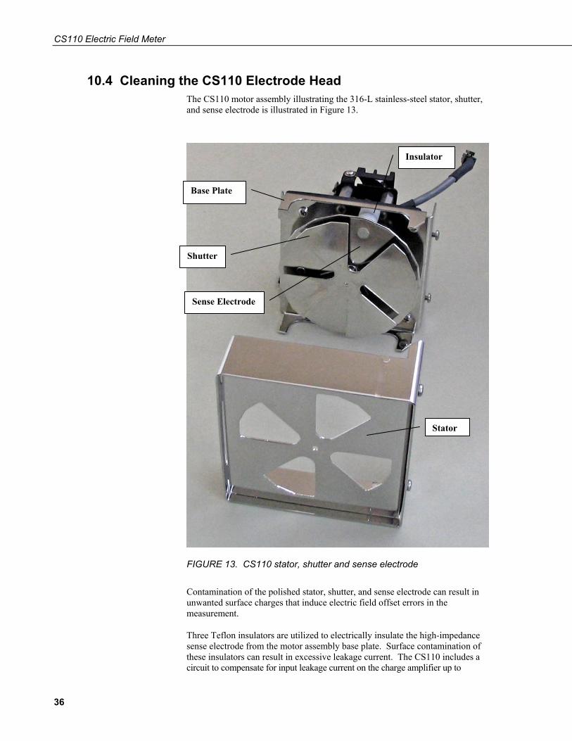
10.4 Cleaning the CS110 Electrode Head The CS110 motor assembly illustrating the 316-L stainless-steel stator, shutter, and sense electrode is illustrated in Figure 13.
Stator
Insulator
Shutter
Base Plate
Sense Electrode
FIGURE 13. CS110 stator, shutter and sense electrode
Contamination of the polished stator, shutter, and sense electrode can result in unwanted surface charges that induce electric field offset errors in the measurement.
Three Teflon insulators are utilized to electrically insulate the high-impedance sense electrode from the motor assembly base plate. Surface contamination of these insulators can result in excessive leakage current. The CS110 includes a circuit to compensate for input leakage current on the charge amplifier up to
36

CS110 Electric Field Meter
±4.2 nA. Leakage current values in excess of ±4.2 nA can cause measurement errors and are indicated by status = 11.
Cleaning of the CS110 electrodes and/or insulators is recommended if any of the following conditions occur:
• When insulators are dry, and leakage current exceeds ± 4.2 nA as indicated by status = 11.
• Visual evidence of contamination (salt deposits, scaling, dust, spider webs etc.) on or around electrode area.
• Zero field reading with Zero Electric Field Cover (PN: 17642) exceeds ± 60 V/m. Note: it is important that the inside of the zero field cover also be clean for good zero field reading.
Electrode Cleaning Procedure:
1. Remove the stator by loosening the 2 Philips head screws on the motor assembly base plate, allowing the stator to pivot and be removed.
2. Inspect the stator for any contaminant deposits and scrub such deposits off with soap and hot water if available. Any residue may form non-conductive layers that can hold unwanted surface charge. Using a brush that will fit between the shutter and the sense electrode, carefully wash the shutter and sense electrode, along with the three insulators attaching the sense electrode to the main body of the CS110. One brush (CSI PN 17578) ships with each CS1110. Large offsets are likely due to electrical charges residing insulative deposits on metallic surfaces, while large leakage currents are likely due to contaminated insulators.
3. Rinse well, using de-ionized water if available, and blow dry with air. Note: Rubbing and wiping tends to induce unwanted surface charging that will eventually dissipate.
4. Reassemble the stator making sure it is positioned properly before tightening the two Philips head stator screws. Try and avoid getting fingerprints, etc. on clean electrodes as they can result in unwanted surface charge. (Clean cotton gloves are helpful.)
5. Attach the zero field cover plate (PN: 17642) to the stator and verify that the leakage current ≤ ⎢0.5 nA⎟ and that the zero field offset ≤ 60 V/m. Leakage current > ⎢0.5 nA⎟ and/or zero field offsets > 60 V/m indicate problems with cleanliness and/or unwanted surface charge.
10.5 Changing Desiccant The CS110 is shipped with desiccant inside the sealed case to reduce humidity for the sensitive electronics enclosed. A humidity sensor is also contained inside the CS110 case to allow monitoring of the internal relative humidity. The following CRBasic instruction provides internal humidity data to the variable Internal_RH, which can be included in an output table.
37

CS110 Electric Field Meter
VoltDiff(Internal_RH,1,mV2500,5,True,0,250,0.1,0) 'Internal humidity measure.
Changing of CS110 desiccant is recommended for internal relative humidity values ≥80%.
FIGURE 14. Inside of CS110 case illustrating bracket for holding desiccant
Replacement intervals less than once every six months for the 4 Unit (PN: 4905) desiccant pack within the sealed CS110 case indicate a problem with the CS110 case seal or with the desiccant packs being used.
NOTE
Procedure for Changing Desiccant:
1. Remove the CS110 case lid by unscrewing the captive screws that attach the lid to the main body of the CS110.
38

CS110 Electric Field Meter
2. Inspect the gasket on the CS110 lid making sure that a good seal is possible when the lid is replaced.
3. Remove the old desiccant pack and replace with a new 4 unit desiccant pack (PN: 4905) making sure the new pack is placed into the bracket that prevents the desiccant from sliding into the motor assembly.
10.6 Checking Shutter/Encoder Alignment Status codes 14, 15, and 16 indicate problems with the stepper motor correctly opening and closing the shutter. A mechanical trim procedure is done at the factory to set proper shutter/encoder alignment, as described in Appendix D. Proper shutter/encoder alignment can be verified with the following procedure utilizing the special CS110Shutter instruction which positions the shutter in the fully closed or fully open positions. The following program combines the CS110Shutter instruction with Delay instructions so that fully closed and fully open shutter positions can be verified visually. Stator to shutter overlap exists in the fully opened and fully closed positions so that slight shutter position variations do not alter the exposed area to the sense electrode. A fully opened shutter will display symmetrical stator to shutter overlap, within the 1.8° stepper motor step size, on both edges of each of the 4 openings in the stator when viewed from a perpendicular position to the direction of the shutter blades. No visible gaps between the stator and shutter blades should be visible on a fully closed shutter when viewed from a position perpendicular to the shutter blades.
'Program to open/close the CS110 shutter (CS110_Shutter1.cr1). 'Last updated by Jody Swenson on 9/26/05. Public PTemp Public Batt Public stat(2) DataTable(Efield,1,-1) Sample(2,stat,FP2) Sample(1,PTemp,IEEE4) Sample(1,Batt,IEEE4) EndTable BeginProg Scan(5000,msec,0,0) PanelTemp(PTemp,250) Battery(Batt) CS110Shutter(stat(1),1) 'Fully open shutter. Delay (0,3000,mSec) CS110Shutter(stat(2),0) 'Fully close shutter. CallTable Efield NextScan EndProg
39

CS110 Electric Field Meter
40
10.7 Re-Calibration Re-calibration of measurement instruments is commonly done in data critical applications in order to combat component drift with time. Component drift is a function of the environment experienced by the instrument. High humidity and/or high temperature environments generally cause the most drift. For the CR1000 datalogger a two year re-calibration interval is recommended, with longer intervals being sensible for users that find negligible instrument drift over a two year period. The embedded CR1000 datalogger inside the CS110 case should experience a low-humidity environment, which helps minimize datalogger measurement drift.
As mentioned in Section 5.1, each CS110 is factory calibrated in the parallel plate calibrator illustrated in Figure 5 to determine individual instrument gain. The CS110 electric field measurement instrument gain is a function of electrode dimensions, along with the 1% feedback capacitor used in the charge amplifier. While measurement drift of CR1000 is likely negligible with regard to the ±5% of reading accuracy specification of electric field measurements, datalogger drift may be a factor for the measurement of temperature by means of an external temperature and RH probe.
A parallel-plate calibration is recommended whenever any electrodes are bent, removed or replaced, with the exception of the removal and replacement of the same stator during the process of insulator cleaning. For CS110 applications requiring long-term electric field measurement accuracy better than ± 10%, a parallel plate factory calibration is recommended every three years.
The expected lifetime of the CS110 is 5 to 10 years, again depending upon the operational environment. Instruments operated in coastal environments will likely suffer from external finish degradation and/or operational failure sooner than instruments operated in dry inland environments.
11. References “Lightning Physics and Effects” by Vladimir A. Rakov and Martin A. Uman, Cambridge University Press, 2003.
“The Electrical Nature of Storms” by Donald R. MacGorman, and W. David Rust, Oxford University Press, Inc., 1998.
“On some determinations of the sign and magnitude of electric discharges in lightning flashes” by C.T.R. Wilson, Proceedings of the Royal Society, Series A, Vol. 92, 555-574, 1916.
“Industrial Electrostatics – fundamentals and measurements” by D.M. Taylor and P.E. Secker, John Wiley & Sons Inc. 1994, pg. 36-38.
(LPLWS) METEOROLOGICAL\CCAFS\81900\LAUNCH PAD LIGHTNING WARNING SYSTEM (http://www-sdd.fsl.noaa.gov/RSA/lplws/LPLWS-handbook.Apr03.pdf). Please note that the web site address is case sensitive.
NOAA (See www.lightningsafety.noaa.gov\outdoors.htm.)
NAVSEA OP 5, Vol 1, Seventh Rev. Para 6-2, pg 6-1 and 6-2, 2001.

Appendix A. CS110 Measurement Status Codes
Status codes 1 through 3: Good Instrument Health. status = 1, Good instrument health. ±250 mV measurement range only. Return measured Efield value. status = 2, Good instrument health. ±2500 mV measurement range used. Return measured Efield value. status = 3, Good instrument health. NAN returned for Efield because of
measurement over-range on the ±2500 mV measurement range.
No priority issues exist with status codes 1 through 3 since only 1 of these “Good Instrument Health” codes can exist for a given measurement.
Status codes 4 through 6: Good measurement, after properly positioning the shutter. status = 4, Good instrument health. ±250 mV measurement range only.
Had to properly position shutter. status = 5, Good instrument health. ±2500 mV measurement range used.
Had to properly position shutter. status = 6, Good instrument health. NAN returned for Efield because of
measurement over-range on the ±2500 mV measurement range. Had to properly position shutter.
Status code 4 through 6 indicate that the shutter was not properly positioned upon commencing the measurement. The problem was recognized, corrected and a valid measurement made. Status codes 4 through 6 are common upon power up, or if the shutter has been touched or bumped since the last execution of the CS110 instruction. Persisting status codes 4 through 6 indicate a problem with parking the shutter that should be investigated.
Status codes 7 through 10: Datalogger warnings and errors. status = 7, +5Vext low. Return measured Efield value. status = 8, Datalogger skipped scan. Return measured Efield value. status = 9, Input power < 9.6 V. Return measured Efield value. status = 10, Datalogger watchdog reset. Return measured Efield value.
Status codes 7, through 10 increase in priority with 7 being the lowest and 10 the highest of the warning and error codes. Status code 7 is a low priority error message, as low +5Vext is a concern, but does not corrupt electric field measurements. Status code 7 is overwritten by any other warning and error code (i.e. status ≥ 7), including Leakage current exceeds compensation range.
Status codes 8 through 10 are the highest priority error messages returned by the CS110, and will overwrite other lesser errors that occur simultaneously during the CS110 instruction. Since only one status value can be returned from a CS110 instruction, status 10 is given the highest priority, status 9 the second highest, and 8 the third highest priority of CS110 status codes. Next in priority are codes 16, 15, 14, 13, 12, and 11 followed by 7, 6, 5, 4, 3, 2 and 1.
A-1
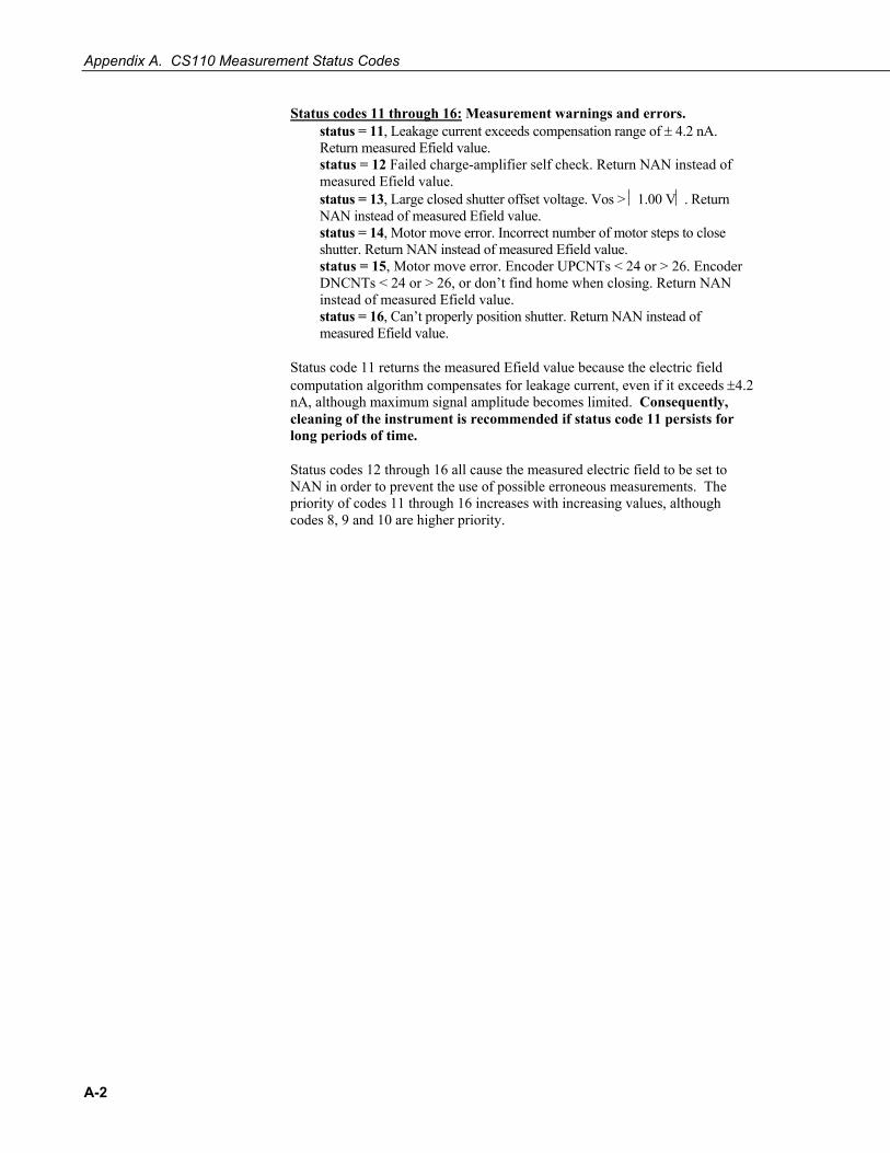
Appendix A. CS110 Measurement Status Codes
A-2
Status codes 11 through 16: Measurement warnings and errors. status = 11, Leakage current exceeds compensation range of ± 4.2 nA.
Return measured Efield value. status = 12 Failed charge-amplifier self check. Return NAN instead of
measured Efield value. status = 13, Large closed shutter offset voltage. Vos > ⏐1.00 V⏐. Return
NAN instead of measured Efield value. status = 14, Motor move error. Incorrect number of motor steps to close
shutter. Return NAN instead of measured Efield value. status = 15, Motor move error. Encoder UPCNTs < 24 or > 26. Encoder
DNCNTs < 24 or > 26, or don’t find home when closing. Return NAN instead of measured Efield value.
status = 16, Can’t properly position shutter. Return NAN instead of measured Efield value.
Status code 11 returns the measured Efield value because the electric field computation algorithm compensates for leakage current, even if it exceeds ±4.2 nA, although maximum signal amplitude becomes limited. Consequently, cleaning of the instrument is recommended if status code 11 persists for long periods of time.
Status codes 12 through 16 all cause the measured electric field to be set to NAN in order to prevent the use of possible erroneous measurements. The priority of codes 11 through 16 increases with increasing values, although codes 8, 9 and 10 are higher priority.
Appendix B. CS110 Accessories B.1 Zero Electric Field Cover
As previously mentioned, unwanted surface charges residing on non-conductive deposits on electrodes result in a non-zero electric field, even when external electric fields are zero. Polished 316-L stainless-steel is used for critical electrode surfaces on the CS110 to minimize unwanted surface charges. CS110’s with clean electrodes have been found to display electric field offsets less than 20 V/m in absolute value. The CS110 Zero Electric Field Cover (PN: 17642) is used to check the electric field offset voltage of the CS110. If the measured electric field is ≥| 60 V/m| with the Zero Electric Field Cover on, then inspection and cleaning of the electrode surfaces as discussed in Section 10.4 is recommended.
B.2 Upward-Facing Site Calibration Kit As previously mentioned, the CS110 is calibrated in a parallel plate calibration chamber, resulting in a valid calibration for a flush-mounted upward-facing configuration. Yet, inverted and elevated CS110 mounting configurations are recommended for long term installations. Upward-facing site calibration kit (PN: 17579) has been designed to provide a flush-mounted upward-facing configuration for the CS110 to aid in determining site correction factors.
B.3 CR1000 Keyboard Display The CR1000 keyboard display (CR1000KD) is a convenient CR1000 user interface that can be directly connected to the CS110. The CR1000 keyboard display connects to the CS110 through the CS I/O port, requiring a CS110 CS I/O Cable (CS110CBL2-L). The CR1000KD can be used to view data and programs, and to make simple program modifications. Details on the CR1000KD can be found in the CR1000 Measurement and Control System Operators Manual.
B.4 Miscellaneous Peripheral Modules The CS110 is compatible with CSI SDM (Synchronous Device for Measurement) peripherals. The C1, C2, and C3 control ports necessary for SDM are available through the CS110 POWER CABLE (CS110CBL3-L). SDI-12 sensors can also be read using C1 and/or C3.
B-1

Appendix B. CS110 Accessories
B-2

Appendix C. CS110 Connector Pin-outs The following information describes the connectors that mate with the built-in (bulkhead) connectors on the CS110. Connector pin numbering for the 6 and 9 pin connectors are shown below. The view is a view of the solder-cup side of the cabled connector. The circular connectors are Mini-Con-X type from Conxall. The CSI part numbers shown for the connectors include the backshell. CSI fills the backshell with a relatively thick epoxy to seal and provide strain relief.
1
3
2
6
4
5
1
4
2 9
5
7
3 8
6
POWER CONNECTOR
CS110CBL3-L CS110 Power Cable
Connector is female and is CSI PN 17654 (Conxall #6282-6SG-522 or Switchcraft #EN3C6F). Pin 1 is indicated with a dot.
Pin Description Color 1 C1 Control Port 1 Blue 2 +12 V Power Red 3 Gnd Digital Ground Drain (clear) 4 P_Gnd Power Ground Black 5 C3 Control Port 3 Green 6 C2 Control Port 2 Yellow
WIND CONNECTOR
Connector is male and is CSI PN 9889 (Conxall #6282-6PG-522 or Switchcraft #EN3C6M). Pin 1 is indicated with a dot.
Pin Description 1 2LO Single-ended channel 4 1 1Mohm Pin 1 also connects to ground via a 1 Mohm 1% 50ppm resistor 2 Gnd Panel Ground 3 EX2 Excitation channel 2 4 P1 Pulse channel 1 5 Gnd Power ground 6 Gnd Ground
C-1
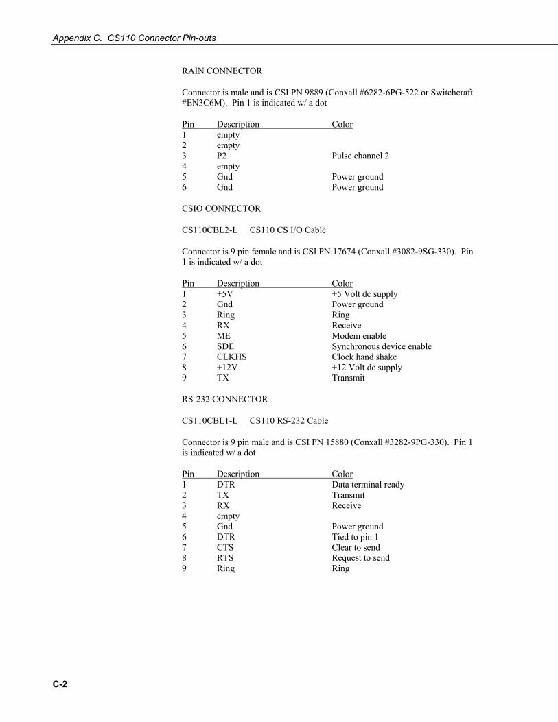
Appendix C. CS110 Connector Pin-outs
RAIN CONNECTOR
Connector is male and is CSI PN 9889 (Conxall #6282-6PG-522 or Switchcraft #EN3C6M). Pin 1 is indicated w/ a dot
Pin Description Color 1 empty 2 empty 3 P2 Pulse channel 2 4 empty 5 Gnd Power ground 6 Gnd Power ground
CSIO CONNECTOR
CS110CBL2-L CS110 CS I/O Cable
Connector is 9 pin female and is CSI PN 17674 (Conxall #3082-9SG-330). Pin 1 is indicated w/ a dot
Pin Description Color 1 +5V +5 Volt dc supply 2 Gnd Power ground 3 Ring Ring 4 RX Receive 5 ME Modem enable 6 SDE Synchronous device enable 7 CLKHS Clock hand shake 8 +12V +12 Volt dc supply 9 TX Transmit
RS-232 CONNECTOR
CS110CBL1-L CS110 RS-232 Cable
Connector is 9 pin male and is CSI PN 15880 (Conxall #3282-9PG-330). Pin 1 is indicated w/ a dot
Pin Description Color 1 DTR Data terminal ready 2 TX Transmit 3 RX Receive 4 empty 5 Gnd Power ground 6 DTR Tied to pin 1 7 CTS Clear to send 8 RTS Request to send 9 Ring Ring
C-2

Appendix C. CS110 Connector Pin-outs
SOLAR RADIATION CONNECTOR
Connector is male and is CSI PN 9889 (Conxall #6282-6PG-522 or Switchcraft #EN3C6M). Pin 1 is indicated w/ a dot
Pin Description 1 3HI Single-ended channel 5 or high side of differential channel 3 2 3LO Single-ended channel 6 or low side of differential channel 3 3 +12V +12 Volt dc supply 4 C4 Control port 4 5 C3 Control port 3 6 Gnd Power ground
TEMP/RH CONNECTOR
Connector is male and is CSI PN 9889 (Conxall #6282-6PG-522 or Switchcraft #EN3C6M). Pin 1 is indicated w/ a dot
Pin Description Color 1 1HI Single-ended channel 1 or high side of differential channel 1 2 1LO Single-ended channel 2 or low side of differential channel 1 2 1Kohm Pin 2 also connects to ground via a 1 Kohm 0.1% 10 ppm/C
resistor 3 empty 4 +12Vsw Switched +12 volt dc supply 5 Gnd Ground 6 Gnd Power ground
C-3

Appendix C. CS110 Connector Pin-outs
C-4
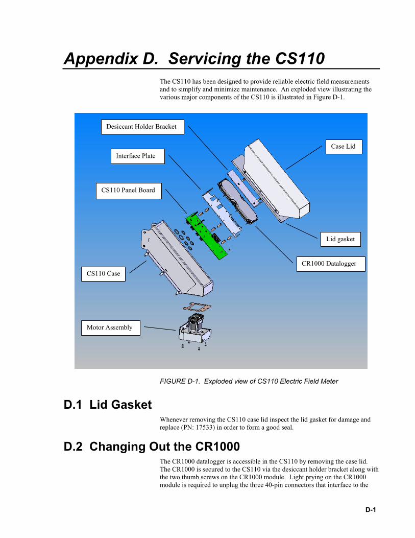
Appendix D. Servicing the CS110 The CS110 has been designed to provide reliable electric field measurements and to simplify and minimize maintenance. An exploded view illustrating the various major components of the CS110 is illustrated in Figure D-1.
Desiccant Holder Bracket
Case Lid
FIGURE D-1. Exploded view of CS110 Electric Field Meter
D.1 Lid Gasket Whenever removing the CS110 case lid inspect the lid gasket for damage and replace (PN: 17533) in order to form a good seal.
D.2 Changing Out the CR1000 The CR1000 datalogger is accessible in the CS110 by removing the case lid. The CR1000 is secured to the CS110 via the desiccant holder bracket along with the two thumb screws on the CR1000 module. Light prying on the CR1000 module is required to unplug the three 40-pin connectors that interface to the
Motor Assembly
CR1000 Datalogger
CS110 Panel Board
Interface Plate
Lid gasket
CS110 Case
D-1

Appendix D. Servicing the CS110
CS110 panel board, after removing the two thumb screws on the CR1000 module.
When installing a CR1000 into the CS110 case, first check for proper orientation of the three 40-pin connectors that interface to the CS110 panel board. Once proper connector orientation is verified, set the CR1000 into the CS110 case and feel for proper positioning of the three 40-pin connectors. When the connector shrouds are engaged, press down firmly on the CR1000 to mate the connector pins, prior to engaging the two thumb screws on the CR1000 module. Replace the desiccant holder bracket and desiccant after tightening the thumb screws.
D.3 Changing Out Motor Assembly First remove the CR1000 by removing the desiccant holder bracket along with the two thumb screws on the CR1000 module. Next remove the black anodized interface plate between the CR1000 and CS110 panel board. Unplug the three locking electrical connectors on the CS110 panel board from the motor assembly.
Remove the stator by loosening the 2 Philips head screws located on the underside of the CS110. Next remove the four Philips head screws that attach the motor assembly to the white powder-coated aluminum case. With the four screws removed, carefully break it free from the bond to the gasket and allow it to be removed through the bottom of the CS110 case. Be sure to check the integrity of the motor assembly gasket on the CS110 case before replacing the motor assembly.
Replacement of the motor assembly invalidates the factory calibration of a CS110 because of possible dimensional differences between assemblies.
NOTE
D.4 Changing Out the CS110 Panel Board Assembly First remove the CR1000 by removing the desiccant holder bracket along with the two thumb screw on the CR1000 module. Next remove the black anodized interface plate between the CR1000 and CS110 panel board.
Next remove the mounting posts that support the black anodized interface plate followed by the two Phillips head screws by the motor assembly that attach the CS110 panel board PCB to the CS110 case. Disconnect the three locking electrical connectors that connect signals between the CS110 panel board and the motor assembly. Next remove the plastic nuts from the circular connectors on the outside of the CS110 case. The CS110 panel board should now be free and can be maneuvered out of the case.
Reverse the above procedure when installing a CS110 panel board PCB. Make sure that the circular connectors each have a functional o-ring before placing the CS110 panel board inside the CS110 case. The plastic nuts on the circular connectors should be tightened to a torque of 10-12 inch⋅lbs.
Readers are referred to Section 10 on Maintenance for instructions on how to clean the CS110 electrodes and change desiccant in the sealed CS110 case.
D-2
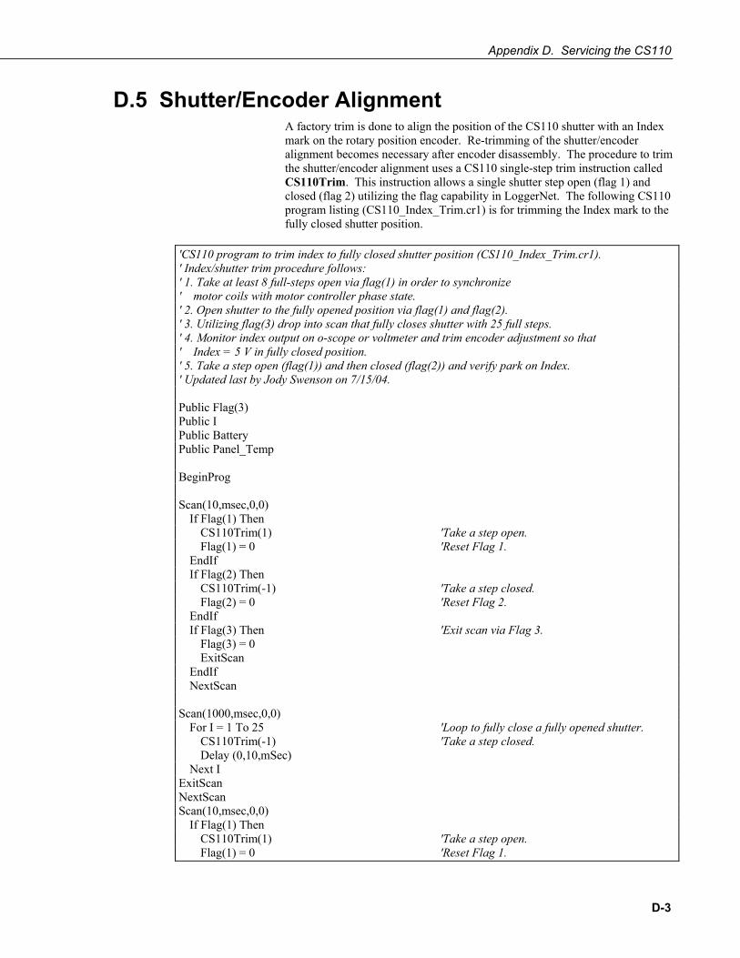
Appendix D. Servicing the CS110
D.5 Shutter/Encoder Alignment A factory trim is done to align the position of the CS110 shutter with an Index mark on the rotary position encoder. Re-trimming of the shutter/encoder alignment becomes necessary after encoder disassembly. The procedure to trim the shutter/encoder alignment uses a CS110 single-step trim instruction called CS110Trim. This instruction allows a single shutter step open (flag 1) and closed (flag 2) utilizing the flag capability in LoggerNet. The following CS110 program listing (CS110_Index_Trim.cr1) is for trimming the Index mark to the fully closed shutter position.
'CS110 program to trim index to fully closed shutter position (CS110_Index_Trim.cr1). ' Index/shutter trim procedure follows: ' 1. Take at least 8 full-steps open via flag(1) in order to synchronize ' motor coils with motor controller phase state. ' 2. Open shutter to the fully opened position via flag(1) and flag(2). ' 3. Utilizing flag(3) drop into scan that fully closes shutter with 25 full steps. ' 4. Monitor index output on o-scope or voltmeter and trim encoder adjustment so that ' Index = 5 V in fully closed position. ' 5. Take a step open (flag(1)) and then closed (flag(2)) and verify park on Index. ' Updated last by Jody Swenson on 7/15/04. Public Flag(3) Public I Public Battery Public Panel_Temp BeginProg Scan(10,msec,0,0) If Flag(1) Then CS110Trim(1) 'Take a step open. Flag(1) = 0 'Reset Flag 1. EndIf If Flag(2) Then CS110Trim(-1) 'Take a step closed. Flag(2) = 0 'Reset Flag 2. EndIf If Flag(3) Then 'Exit scan via Flag 3. Flag(3) = 0 ExitScan EndIf NextScan Scan(1000,msec,0,0) For I = 1 To 25 'Loop to fully close a fully opened shutter. CS110Trim(-1) 'Take a step closed. Delay (0,10,mSec) Next I ExitScan NextScan Scan(10,msec,0,0) If Flag(1) Then CS110Trim(1) 'Take a step open. Flag(1) = 0 'Reset Flag 1.
D-3

Appendix D. Servicing the CS110
EndIf If Flag(2) Then CS110Trim(-1) 'Take a step closed. Flag(2) = 0 'Reset Flag 2. EndIf NextScan EndProg
The CS110_Index_Trim.cr1 program uses flags 1, 2 and 3 available in LoggerNet, for user control. Flags 1 and 2 are used to single step the shutter one step open and closed, respectively. These flags are used initially to position the shutter into the fully opened position, as observed visually by stator to shutter overlap.
At least 8 consecutive open (flag 1) initiated motor steps should occur prior to arriving at the fully open position in order to guarantee synchronization between the motor controller phase state and the stepper-motor coils being energized.
NOTE
Stator to shutter overlap exists in the fully opened and fully closed positions so that slight shutter position variations do not alter the measured result. A fully opened shutter will display symmetrical stator to shutter overlap, within the 1.8° stepper motor step size, on both edges of each of the 4 openings in the stator.
Once the shutter has been adjusted to the fully open position by means of flags 1 and 2, flag 3 is to be set high to execute a 25 closed step loop, which positions the shutter in the fully closed position, which is the desired position for the Index trim. No visible gaps between the stator and shutter blades should be visible in the fully closed shutter position. Once in the fully closed position, hook an oscilloscope or dc voltmeter to the Index test pin on the CS110 panel PCB. The Ports and Flags button on the LoggerNet connect screen along with a graphical display can also be used for trimming if the update interval is set to 50 ms.
D-4
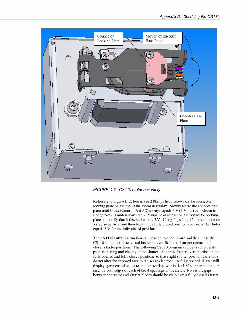
Appendix D. Servicing the CS110
Motion of Encoder Base Plate
EncodePlate
Connector Locking Plate
r Base
FIGURE D-2. CS110 motor assembly
Referring to Figure D-2, loosen the 2 Philips head screws on the connector locking plate on the top of the motor assembly. Slowly rotate the encoder base plate until Index (Control Port # 8) always equals 5 V (5 V = True = Green in LoggerNet). Tighten down the 2 Philips head screws on the connector locking plate and verify that Index still equals 5 V. Using flags 1 and 2, move the motor a step away from and then back to the fully closed position and verify that Index equals 5 V for the fully closed position.
The CS110Shutter instruction can be used to open, pause and then close the CS110 shutter to allow visual inspection/verification of proper opened and closed shutter positions. The following CS110 program can be used to verify proper opening and closing of the shutter. Stator to shutter overlap exists in the fully opened and fully closed positions so that slight shutter position variations do not alter the exposed area to the sense electrode. A fully opened shutter will display symmetrical stator to shutter overlap, within the 1.8° stepper motor step size, on both edges of each of the 4 openings in the stator. No visible gaps between the stator and shutter blades should be visible on a fully closed shutter.
D-5
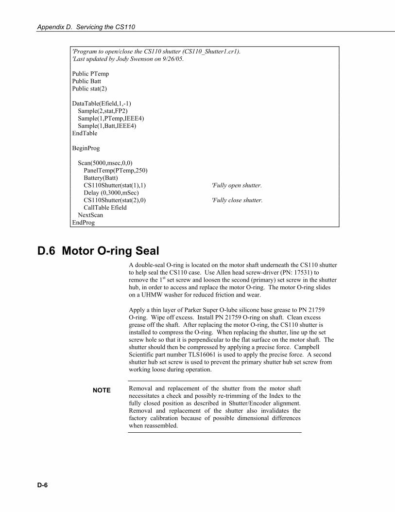
Appendix D. Servicing the CS110
'Program to open/close the CS110 shutter (CS110_Shutter1.cr1). 'Last updated by Jody Swenson on 9/26/05. Public PTemp Public Batt Public stat(2) DataTable(Efield,1,-1) Sample(2,stat,FP2) Sample(1,PTemp,IEEE4) Sample(1,Batt,IEEE4) EndTable BeginProg Scan(5000,msec,0,0) PanelTemp(PTemp,250) Battery(Batt) CS110Shutter(stat(1),1) 'Fully open shutter. Delay (0,3000,mSec) CS110Shutter(stat(2),0) 'Fully close shutter. CallTable Efield NextScan EndProg
D.6 Motor O-ring Seal A double-seal O-ring is located on the motor shaft underneath the CS110 shutter to help seal the CS110 case. Use Allen head screw-driver (PN: 17531) to remove the 1st set screw and loosen the second (primary) set screw in the shutter hub, in order to access and replace the motor O-ring. The motor O-ring slides on a UHMW washer for reduced friction and wear.
Apply a thin layer of Parker Super O-lube silicone base grease to PN 21759 O-ring. Wipe off excess. Install PN 21759 O-ring on shaft. Clean excess grease off the shaft. After replacing the motor O-ring, the CS110 shutter is installed to compress the O-ring. When replacing the shutter, line up the set screw hole so that it is perpendicular to the flat surface on the motor shaft. The shutter should then be compressed by applying a precise force. Campbell Scientific part number TLS16061 is used to apply the precise force. A second shutter hub set screw is used to prevent the primary shutter hub set screw from working loose during operation.
Removal and replacement of the shutter from the motor shaft necessitates a check and possibly re-trimming of the Index to the fully closed position as described in Shutter/Encoder alignment. Removal and replacement of the shutter also invalidates the factory calibration because of possible dimensional differences when reassembled.
NOTE
D-6

Appendix E. CS110 as a Slow Antenna As previously mentioned the CS110 can sample the external electric field at a maximum rate of 5 Hz (200 ms) using the CS110 instruction. Faster sampling of the rapid electric field changes associated with lightning discharges is desirable in some applications, and can be accomplished with the CS110 electric field meter configured as a Slow Antenna which is sometimes called a field change meter.
E.1 Response of the CS110 Slow Antenna in the Frequency Domain
The CS110 as a Slow Antenna with the 250 µs integration responds to events as shown in Figure E-1. The lower frequency limit is due to the measurement circuitry and the upper frequency limit is a function of the integration time. Both are explained below.
The CS110Shutter instruction can be used to fully open the shutter, indefinitely exposing the sense electrode to external fields. Execution of the CS110Shutter instruction with the “open” command changes the CS110 panel board charge amplifier circuitry to a slow antenna by switching in a 200 MΩ resistor in parallel with the 330 pF feedback capacitor, resulting in a (330pF)⋅(200MΩ) = 66 ms decay time constant. In this slow antenna configuration the charge amplifier has a high-pass filter frequency response with the lower cutoff frequency defined by the decay time constant such that f3dB = (2⋅π⋅R⋅C)-1 = 2.4 Hz. This means that events with frequencies higher than 2.4 Hz (shorter than 417 ms) are “passed through” while lower frequency events are “cut off” (search “cutoff frequency” in Wikipedia). The -3dB point for voltage is:
trueof 0.708==− − 10/3103dB
The CS110 can measure the slow antenna output at rates up to 50 Hz (100 Hz may be possible but it has not been tested), using the fast integration (250 μs integration) for the VoltDiff instruction. Voltage measurements using the 250 μs integration duration for the analog integrator, result in an upper 3 dB bandwidth of 1.8 kHz (0.555 ms). Figure E-1 shows the combined effect of both filters.
E-1

Appendix E. CS110 as a Slow Antenna
0.1 1 10 100 1 10 3× 1 10 4×0
0.167
0.333
0.5
0.667
0.833
1Overall Frequency Response of CS110 Slow-Antenna Measurement with 250 us Integration
Frequency (Hz)
Rel
ativ
e M
agni
tude
0.999
0
MagSys f( )
100000.1 f
FIGURE E-1. CS110 slow antenna frequency response
E-2
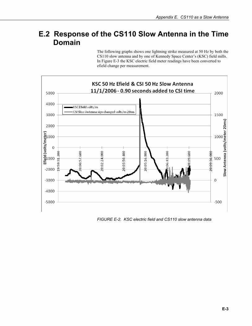
Appendix E. CS110 as a Slow Antenna
E.2 Response of the CS110 Slow Antenna in the Time Domain
The following graphs shows one lightning strike measured at 50 Hz by both the CS110 slow antenna and by one of Kennedy Space Center’s (KSC) field mills. In Figure E-3 the KSC electric field meter readings have been converted to efield change per measurement.
FIGURE E-2. KSC electric field and CS110 slow antenna data
E-3

Appendix E. CS110 as a Slow Antenna
FIGURE E-3. KSC electric field change and CS110 slow antenna data
The KSC electric field mill and the CS110 were not precisely synced accounting for some of the differences in the data shown in the above graph. Since that time, the CS110 has been improved and now has the ability to sync to within ±10 µs of the GPS signal’s PPS pulse. The resolution of accuracy for the clock set is 10 microseconds if the internal CR1000 datalogger has a hardware revision number greater than 007 (RevBoard field in the datalogger's Status table).
E-4

Appendix E. CS110 as a Slow Antenna
E.3 Programming The following CRBasic program utilizes the slow antenna capability of the CS110.
'Program to use the CS110 in slow antenna mode (slowant1.cr1). 'Last updated by Jody Swenson on 9/30/05. PipeLineMode Const Mult = 85 Public Delta_E Public Delta_E_mV2500 Public stat(2) Public E_field Public Leakage DataTable(SlowAnt,1,-1) Sample(1,Delta_E,IEEE4) EndTable BeginProg CS110 (E_field,Leakage,stat(1),250,Mult,0) 'Measure E_field and leakage. CS110Shutter(stat(2),1) 'Fully open shutter. Scan(20,msec,0,0) VoltDiff (Delta_E,1,mV250,8,False,0,250,Mult,0) 'no input reversal. VoltDiff (Delta_E_mV2500,1,mV2500,8,False,0,250,Mult,0) 'no input reversal. If Delta_E = NAN Then Delta_E = Delta_E_mV2500 EndIf CallTable SlowAnt NextScan EndProg
In the above program the PipeLineMode instruction enables parallel task processing necessary to complete a scan in 20 ms. The CS110 instruction following the BeginProg statement provides a measure of the absolute electric field along with a leakage current compensation value, and is only executed once. The CS110Shutter instruction can fully open or fully close the shutter, based on the whether the 2nd parameter is a 1, or 0, respectively. Two VoltDiff instructions are used on two different input voltage ranges to provide more dynamic range in the charge amplifier output measurement.
The CS110 can be programmed to operate as a field meter and then switch to operate as a slow antenna. For example, efield measurements may be desired until they exceed an alarm threshold of ±1500 V/m after which slow antenna (field change) measurements may be desired. The CR1000 operating system does not allow the Sequential Mode command and the Pipeline Mode command used in the above example to exist in the same program. For the CS110 to be able to switch between measuring the electric field with the CS110 instruction and the electric field change in the “slow antenna” mode, the slow antenna instructions must be run in the Sequential Mode. One way to accomplish this would be to program the CR1000 to monitor a 1 minute running average of the efield and when it exceeds ±1500 v/m switch to the slow antenna mode for a fixed amount of time and then return to the field meter mode.
E-5

Appendix E. CS110 as a Slow Antenna
E-6
E.4 Calibration The factory calibration described in Section 5 applies to the maximum amplitude of the step response of the CS110 when it is operating as a slow antenna. Switching in the 200 MΩ resistor in the feedback path simply slows the decay of the signal induced on the sense electrode resulting in a 66 millisecond decay time constant
The CS110 operating as a slow antenna returns the change in the electric field with units of volts per meter per scan. A 50 Hz scan interval would yield: X volts * meter-1 * 20 ms-1.
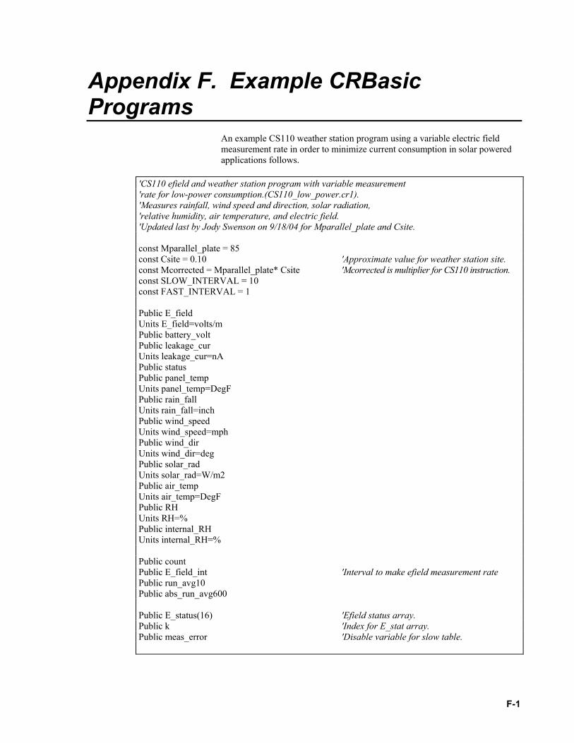
Appendix F. Example CRBasic Programs
An example CS110 weather station program using a variable electric field measurement rate in order to minimize current consumption in solar powered applications follows.
'CS110 efield and weather station program with variable measurement 'rate for low-power consumption.(CS110_low_power.cr1). 'Measures rainfall, wind speed and direction, solar radiation, 'relative humidity, air temperature, and electric field. 'Updated last by Jody Swenson on 9/18/04 for Mparallel_plate and Csite. const Mparallel_plate = 85 const Csite = 0.10 'Approximate value for weather station site. const Mcorrected = Mparallel_plate* Csite 'Mcorrected is multiplier for CS110 instruction. const SLOW_INTERVAL = 10 const FAST_INTERVAL = 1 Public E_field Units E_field=volts/m Public battery_volt Public leakage_cur Units leakage_cur=nA Public status Public panel_temp Units panel_temp=DegF Public rain_fall Units rain_fall=inch Public wind_speed Units wind_speed=mph Public wind_dir Units wind_dir=deg Public solar_rad Units solar_rad=W/m2 Public air_temp Units air_temp=DegF Public RH Units RH=% Public internal_RH Units internal_RH=% Public count Public E_field_int 'Interval to make efield measurement rate Public run_avg10 Public abs_run_avg600 Public E_status(16) 'Efield status array. Public k 'Index for E_stat array. Public meas_error 'Disable variable for slow table.
F-1
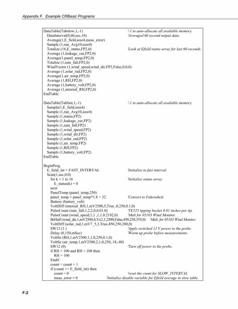
Appendix F. Example CRBasic Programs
DataTable(Tabslow,1,-1) '-1 to auto-allocate all available memory. DataInterval(0,60,sec,10) 'Averaged 60 second output data. Average(1,E_field,ieee4,meas_error) Sample (1,run_Avg10,ieee4) Totalize (16,E_status,FP2,0) 'Look at Efield status array for last 60 seconds. Average (1,leakage_cur,FP2,0) Average(1,panel_temp,FP2,0) Totalize (1,rain_fall,FP2,0) WindVector (1,wind_speed,wind_dir,FP2,False,0,0,0) Average (1,solar_rad,FP2,0) Average(1,air_temp,FP2,0) Average (1,RH,FP2,0) Average (1,battery_volt,FP2,0) Average (1,internal_RH,FP2,0) EndTable DataTable(Tabfast,1,-1) '-1 to auto-allocate all available memory. Sample(1,E_field,ieee4) Sample (1,run_Avg10,ieee4) Sample (1,status,FP2) Sample (1,leakage_cur,FP2) Sample (1,rain_fall,FP2) Sample (1,wind_speed,FP2) Sample (1,wind_dir,FP2) Sample (1,solar_rad,FP2) Sample (1,air_temp,FP2) Sample (1,RH,FP2) Sample (1,battery_volt,FP2) EndTable BeginProg E_field_int = FAST_INTERVAL 'Initialize to fast interval. Scan(1,sec,0,0) for k = 1 to 16 'Initialize status array. E_status(k) = 0 next PanelTemp (panel_temp,250) panel_temp = panel_temp*1.8 + 32 'Convert to Fahrenheit. Battery (battery_volt) VoltDiff (internal_RH,1,mV2500,5,True ,0,250,0.1,0) PulseCount (rain_fall,1,2,2,0,0.01,0) 'TE525 tipping bucket 0.01 inches per tip. PulseCount (wind_speed,1,1 ,1,1,0.2192,0) 'Mult for 05103 Wind Monitor. BrHalf (wind_dir,1,mV2500,4,Vx2,1,2500,False,450,250,355,0) 'Mult. for 05103 Wind Monitor. VoltDiff (solar_rad,1,mV7_5,3,True,450,250,200,0) SW12 (1 ) 'Apply switched 12 V power to the probe. Delay (0,150,mSec) 'Warm up probe before measurements. VoltSe (RH,1,mV2500,1,1,0,250,0.1,0) VoltSe (air_temp,1,mV2500,2,1,0,250,.18,-40) SW12 (0) 'Turn off power to the probe. if RH > 100 and RH < 108 then RH = 100 Endif count = count + 1 if (count >= E_field_int) then count = 0 'reset the count for SLOW_INTERVAL meas_error = 0 'Initialize disable variable for Efield average in slow table.
F-2

Appendix F. Example CRBasic Programs
CS110(E_field,leakage_cur,status,_60Hz,Mcorrected,0) If E_field = NAN Then meas_error = 1 'Disable output to slow table if efield = NAN. E_field_int = FAST_INTERVAL 'Go to fast interval if NAN. EndIf E_status(status) = 1 'Set appropriate element in status array. Endif If E_field <> NAN Then AvgRun (run_avg10,1,E_field,10) 'Used for average output in fast table. AvgRun (abs_run_avg600,1,ABS(E_field),600) 'Used to stay longer at fast interval. EndIf if (E_field>100 or ABS(E_field)>=300 or abs_run_avg600>=300)and (battery_volt>11.0) then E_field_int = FAST_INTERVAL else E_field_int = SLOW_INTERVAL EndIf If E_field_int = FAST_INTERVAL Then CallTable Tabfast 'Only call fast table when fast efield active EndIf CallTable Tabslow 'Call slow every time at slow interval. NextScan EndProg
In the above program all measurements, except the electric field measurement, are done once per second. The electric field measurement is done once every SLOW_INTERVAL when measured electric field values are between -300 V/m and +100 V/m as determined by an if statement. The -300 V/m and +100 V/m values are somewhat arbitrary and can easily be changed to better suit a given application. When measured electric field values fall outside of the -300 V/m and +100 V/m range, the electric field measurement rate becomes the FAST_INTERVAL. A running average instruction (AvgRun) is used to maintain measurements at the FAST_INTERVAL for some time following elevated electric fields, even after several near zero measurements.
F-3

Appendix F. Example CRBasic Programs
F-4

Appendix G. CS110 2 Meter CM10 Tripod Site
FIGURE G-1. CS110 2 Meter CM10 Tripod site
The Tripod_CS110 site consists of the CS110 mounted on the CM10 Tripod at a height of 2 meters, and a 12 x 14 inch enclosure.
The following may affect the site calibration factor, Csite:
• CM10 Tripod • CS110 Electric Field Meter • ENC 12/14 Enclosure
If the above items are installed using the following set of instructions, the site is level with a 25 foot (762 cm) radius of gravel around the tripod and there are no obstructions higher than 18 degrees from the center of a measurement site2 then the Csite determined for this configuration should be valid.
G-1
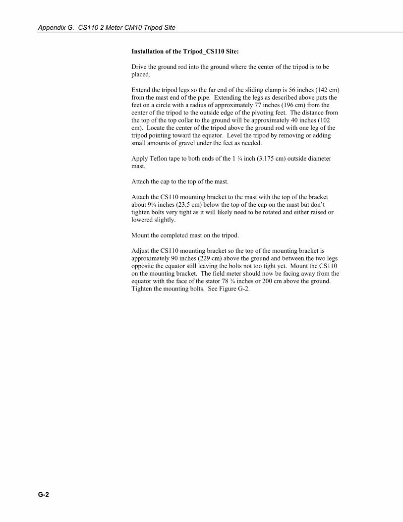
Appendix G. CS110 2 Meter CM10 Tripod Site
Installation of the Tripod_CS110 Site:
Drive the ground rod into the ground where the center of the tripod is to be placed.
Extend the tripod legs so the far end of the sliding clamp is 56 inches (142 cm) from the mast end of the pipe. Extending the legs as described above puts the feet on a circle with a radius of approximately 77 inches (196 cm) from the center of the tripod to the outside edge of the pivoting feet. The distance from the top of the top collar to the ground will be approximately 40 inches (102 cm). Locate the center of the tripod above the ground rod with one leg of the tripod pointing toward the equator. Level the tripod by removing or adding small amounts of gravel under the feet as needed.
Apply Teflon tape to both ends of the 1 ¼ inch (3.175 cm) outside diameter mast.
Attach the cap to the top of the mast.
Attach the CS110 mounting bracket to the mast with the top of the bracket about 9¼ inches (23.5 cm) below the top of the cap on the mast but don’t tighten bolts very tight as it will likely need to be rotated and either raised or lowered slightly.
Mount the completed mast on the tripod.
Adjust the CS110 mounting bracket so the top of the mounting bracket is approximately 90 inches (229 cm) above the ground and between the two legs opposite the equator still leaving the bolts not too tight yet. Mount the CS110 on the mounting bracket. The field meter should now be facing away from the equator with the face of the stator 78 ¾ inches or 200 cm above the ground. Tighten the mounting bolts. See Figure G-2.
G-2

Appendix G. CS110 2 Meter CM10 Tripod Site
FIGURE G-2. CS110 on CM10 Tripod Mast
Mount the fiberglass enclosure to the top of the leg facing the equator with the top bracket approximately 2 inches (5 cm) below the top of the leg. Be careful opening the lid because in this almost horizontal position it is possible to pull the hinge rivets out of the enclosure.
If there is a solar panel, install the solar panel on the leg facing the equator below the enclosure. Tilt the solar panel at an angle less than horizontal that is equal to the latitude plus 10 degrees (see solar panel manual).
Ground the CS110 Electric Field Meter (Figure G-2), the tripod, and the battery (through the enclosure ground) with three separate ground wires as shown in Figure G-3. Power and communication cables should be run down the equator side of the mast and under the enclosure as shown. Wire-tie all cables into place so they don’t move with the wind.
G-3
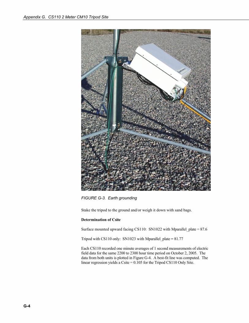
Appendix G. CS110 2 Meter CM10 Tripod Site
FIGURE G-3. Earth grounding
Stake the tripod to the ground and/or weigh it down with sand bags.
Determination of Csite
Surface mounted upward facing CS110: SN1022 with Mparallel_plate = 87.6
Tripod with CS110 only: SN1023 with Mparallel_plate = 81.77
Each CS110 recorded one minute averages of 1 second measurements of electric field data for the same 2200 to 2300 hour time period on October 2, 2005. The data from both units is plotted in Figure G-4. A best-fit line was computed. The linear regression yields a Csite = 0.105 for the Tripod CS110 Only Site.
G-4
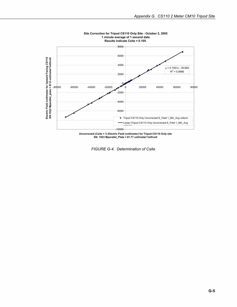
Appendix G. CS110 2 Meter CM10 Tripod Site
Site Correction for Tripod CS110 Only Site - October 2, 20051 minute average of 1 second data
Results indicate Csite = 0.105.
y = 0.1051x - 35.664R2 = 0.9996
-10000
-8000
-6000
-4000
-2000
0
2000
4000
6000
8000
-80000 -60000 -40000 -20000 0 20000 40000 60000 80000
Uncorrected (Csite = 1) Electric Field (volt/meter) for Tripod CS110 Only siteSN: 1023 Mparallel_Plate = 81.77 volt/meter*millivolt
Elec
tric
Fie
ld (v
olt/m
eter
for U
pwar
d Fa
cing
CS1
10
SN:1
022
Mpa
ralle
l_pl
ate
= 87
.6 v
olt/m
eter
*mill
ivol
t
Tripod CS110 Only Uncorrected E_Field 1_Min_Avg volts/m
Linear (Tripod CS110 Only Uncorrected E_Field 1_Min_Avgvolts/m)
FIGURE G-4. Determination of Csite
G-5

Appendix G. CS110 2 Meter CM10 Tripod Site
G-6

Appendix H. Tripod CS110 and StrikeGuard Site H.1 Tripod CS110 and StrikeGuard
FIGURE H-1. Tripod CS110 and StrikeGuard
The Tripod CS110 and StrikeGuard Site includes the following that affect Csite:
• CM10 Tripod • StrikeGuard Lightning Detector • CS110 Electric Field Meter • ENC 12/14 Enclosure
If the above items are installed using the following set of instructions, the site is level with a 25 foot radius of gravel around the tripod and there are no obstructions higher than 18 degrees from the center of a measurement site2 then the Csite determined for this configuration should be valid.
H-1
Appendix H. Tripod CS110 and StrikeGuard Site
H.1.1 Installation of the Tripod CS110 and StrikeGuard Site Drive the ground rod into the ground where the center of the tripod is to be placed.
Extend the tripod legs so the far end of the sliding clamp is 56 inches (142 cm) from the mast end of the pipe. Extending the legs as described above puts the feet on a circle with a radius of approximately 77 inches (196 cm) from the center of the tripod to the outside edge of the pivoting feet. The distance from the top of the top collar to the ground will be approximately 40 inches (102 cm). Locate the center of the tripod above the ground rod with one leg of the tripod pointing toward the equator. Level the tripod by removing or adding small amounts of gravel under the feet as needed.
Apply Teflon tape to both ends of the 1 ¼ inch (3.175 cm) outside diameter mast.
Attach the cap to the top end of the mast.
Attach the CS110 mounting bracket to the mast with the top of the bracket about 9¼ inches (23.5 cm) below the top of the cap on the mast but don’t tighten bolts very tight as it will likely need to be rotated and either raised or lowered slightly.
Mount the completed mast and cross arm on the tripod.
Adjust the CS110 mounting bracket so the top of the mounting bracket is approximately 90 inches (229 cm) above the ground and between the two legs opposite the equator still leaving the bolts not too tight yet. Mount the CS110 on the mounting bracket. The field meter should now be facing away from the equator with the face of the stator 78 ¾ inches or 200 cm above the ground. Tighten the mounting bolts. See Figure H-2.
Mount the StrikeGuard Lightning Detector to the top of the mast on the equator side of the mast with the top of the mounting bracket butted up against the cap on the top of the mast.
H-2

Appendix H. Tripod CS110 and StrikeGuard Site
FIGURE H-2. CS110 and StrikeGuard on tripod mast
Mount the fiberglass enclosure to the top of the leg facing the equator with the top bracket approximately 2 inches (5 cm) below the top of the leg. Be careful opening the lid because in this almost horizontal position it is possible to pull the hinge rivets out of the enclosure.
If there is a solar panel, install the solar panel on the leg facing the equator below the enclosure. Tilt the solar panel at an angle less than horizontal that is equal to the latitude plus 10 degrees (see solar panel manual).
Ground the CS110 Electric Field Meter (Figure H-3), the tripod, and the battery (through the enclosure ground) with three separate ground wires as shown in Figure H-4.
H-3

Appendix H. Tripod CS110 and StrikeGuard Site
FIGURE H-3. Grounding the CS110 grounding strap
H-4
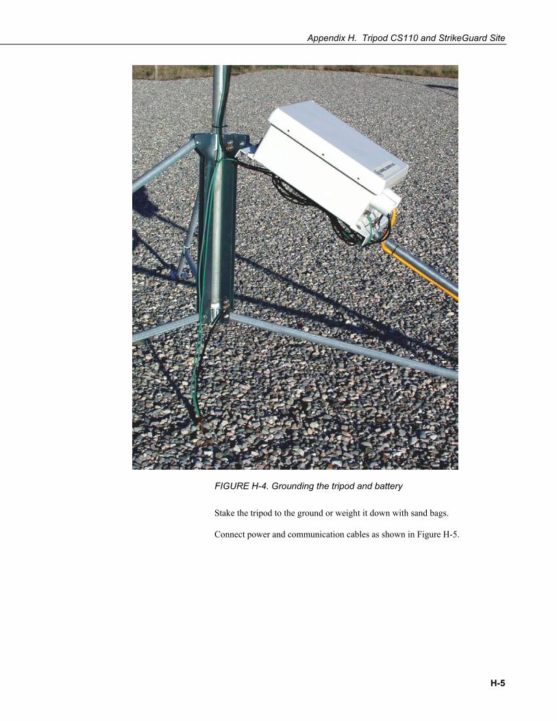
Appendix H. Tripod CS110 and StrikeGuard Site
FIGURE H-4. Grounding the tripod and battery
Stake the tripod to the ground or weight it down with sand bags.
Connect power and communication cables as shown in Figure H-5.
H-5

Appendix H. Tripod CS110 and StrikeGuard Site
FIGURE H-5. Connections for combined system
H-6
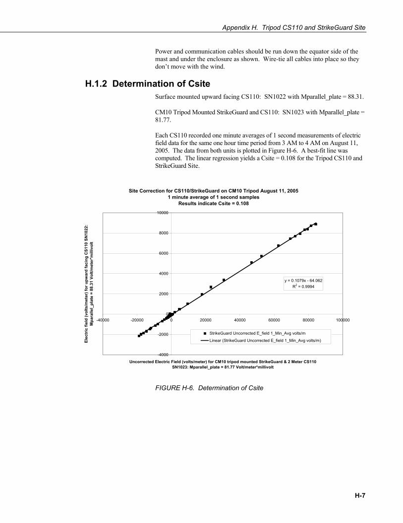
Appendix H. Tripod CS110 and StrikeGuard Site
Power and communication cables should be run down the equator side of the mast and under the enclosure as shown. Wire-tie all cables into place so they don’t move with the wind.
H.1.2 Determination of Csite Surface mounted upward facing CS110: SN1022 with Mparallel_plate = 88.31.
CM10 Tripod Mounted StrikeGuard and CS110: SN1023 with Mparallel_plate = 81.77.
Each CS110 recorded one minute averages of 1 second measurements of electric field data for the same one hour time period from 3 AM to 4 AM on August 11, 2005. The data from both units is plotted in Figure H-6. A best-fit line was computed. The linear regression yields a Csite = 0.108 for the Tripod CS110 and StrikeGuard Site.
Site Correction for CS110/StrikeGuard on CM10 Tripod August 11, 20051 minute average of 1 second samples
Results indicate Csite = 0.108
y = 0.1079x - 64.062R2 = 0.9994
-4000
-2000
0
2000
4000
6000
8000
10000
-40000 -20000 0 20000 40000 60000 80000 100000
Uncorrected Electric Field (volts/meter) for CM10 tripod mounted StrikeGuard & 2 Meter CS110SN1023: Mparallel_plate = 81.77 Volt/meter*millivolt
Elec
tric
fiel
d (v
olts
/met
er) f
or u
pwar
d fa
cing
CS1
10 S
N10
22:
Mpa
ralle
l_pl
ate
= 88
.31
Volt/
met
er*m
illiv
olt
StrikeGuard Uncorrected E_field 1_Min_Avg volts/m
Linear (StrikeGuard Uncorrected E_field 1_Min_Avg volts/m)
FIGURE H-6. Determination of Csite
H-7

Appendix H. Tripod CS110 and StrikeGuard Site
H-8


Campbell Scientific Companies
Campbell Scientific, Inc. (CSI) 815 West 1800 North Logan, Utah 84321 UNITED STATES
www.campbellsci.com • [email protected]
Campbell Scientific Africa Pty. Ltd. (CSAf) PO Box 2450
Somerset West 7129 SOUTH AFRICA
www.csafrica.co.za • [email protected]
Campbell Scientific Australia Pty. Ltd. (CSA) PO Box 8108
Garbutt Post Shop QLD 4814 AUSTRALIA
www.campbellsci.com.au • [email protected]
Campbell Scientific do Brazil Ltda. (CSB) Rua Luisa Crapsi Orsi, 15 Butantã
CEP: 005543-000 São Paulo SP BRAZIL www.campbellsci.com.br • [email protected]
Campbell Scientific Canada Corp. (CSC)
11564 - 149th Street NW Edmonton, Alberta T5M 1W7
CANADA www.campbellsci.ca • [email protected]
Campbell Scientific Centro Caribe S.A. (CSCC)
300 N Cementerio, Edificio Breller Santo Domingo, Heredia 40305
COSTA RICA www.campbellsci.cc • [email protected]
Campbell Scientific Ltd. (CSL)
Campbell Park 80 Hathern Road
Shepshed, Loughborough LE12 9GX UNITED KINGDOM
www.campbellsci.co.uk • [email protected]
Campbell Scientific Ltd. (France) 3 Avenue de la Division Leclerc
92160 ANTONY FRANCE
www.campbellsci.fr • [email protected]
Campbell Scientific Spain, S. L. Avda. Pompeu Fabra 7-9, local 1
08024 Barcelona SPAIN
www.campbellsci.es • [email protected]
Please visit www.campbellsci.com to obtain contact information for your local US or International representative.