cs 152 computer architecture and engineering lecture 26 ...cs152/fa06/lecnotes/lec14-2.pdf · in...
TRANSCRIPT
CS 152 L26: Mid-Term II Review UC Regents Fall 2006 © UCB
2006-11-30John Lazzaro
(www.cs.berkeley.edu/~lazzaro)
CS 152 Computer Architecture and Engineering
Lecture 26 – Mid-Term II Review
www-inst.eecs.berkeley.edu/~cs152/
TAs: Udam Saini and Jue Sun
1
CS 152 L26: Mid-Term II Review UC Regents Fall 2006 © UCB
CS 152: What’s left ...
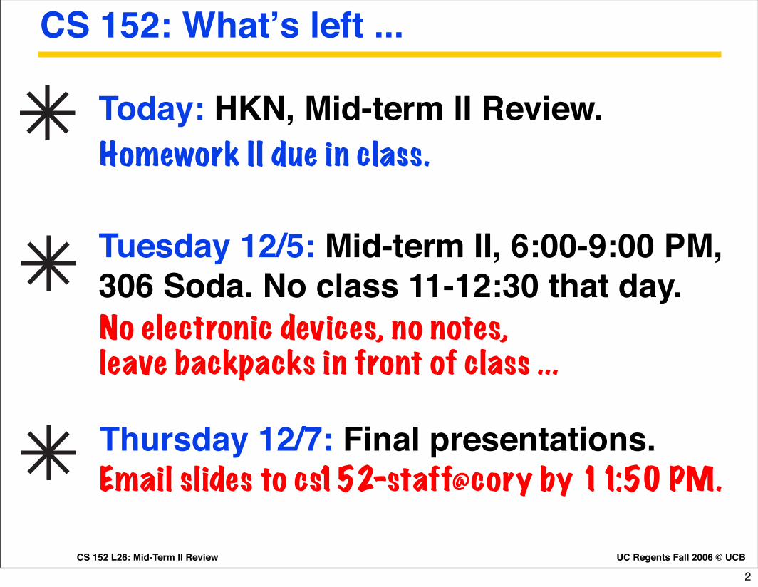
Tuesday 12/5: Mid-term II, 6:00-9:00 PM, 306 Soda. No class 11-12:30 that day.No electronic devices, no notes,leave backpacks in front of class ...
Today: HKN, Mid-term II Review.Homework II due in class.
Thursday 12/7: Final presentations.Email slides to cs152-staff@cory by 11:50 PM.
2

CS 152 L26: Mid-Term II Review UC Regents Fall 2006 © UCB
Mid-Term Review Session
Homework II solutionsSolution PDF will be on website soon after class.
Study guide for Mid-Term II
3
UC Regents Fall 2006 © UCBCS 152 L26: Mid-Term II Review
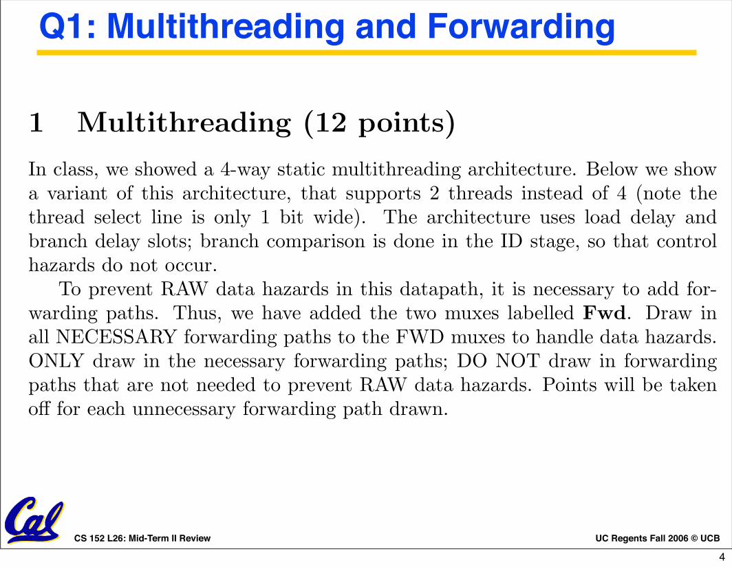
1 Multithreading (12 points)
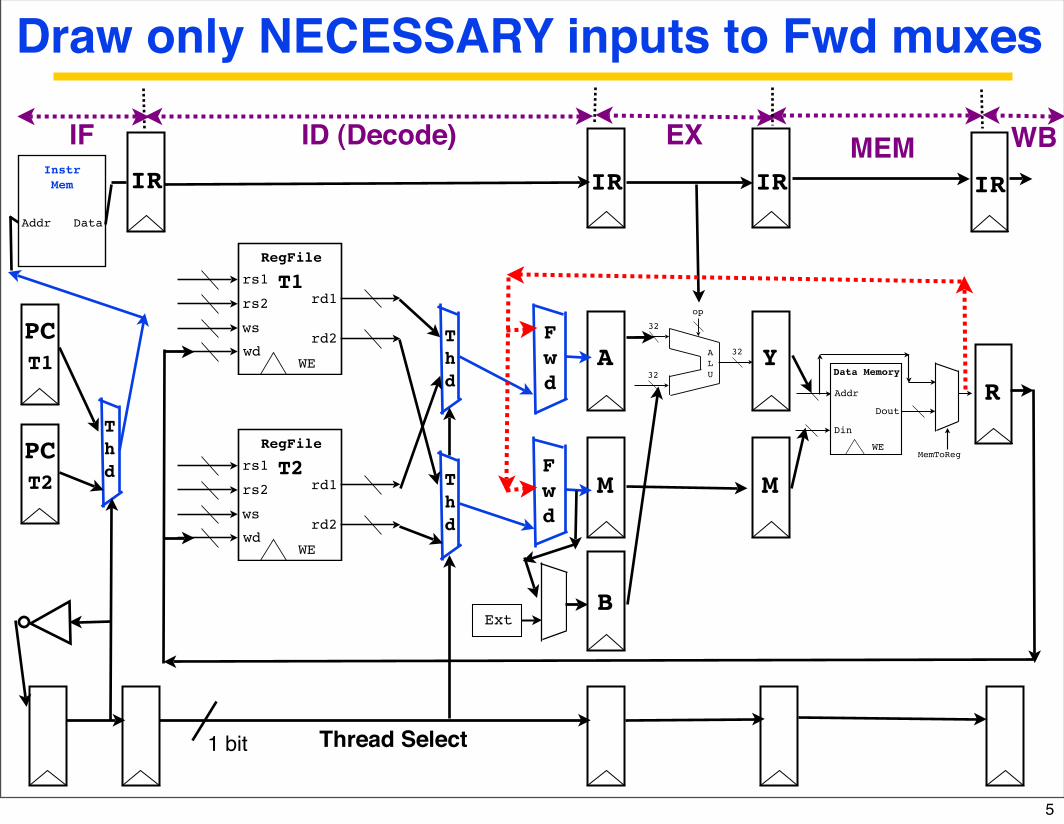
In class, we showed a 4-way static multithreading architecture. Below we showa variant of this architecture, that supports 2 threads instead of 4 (note thethread select line is only 1 bit wide). The architecture uses load delay andbranch delay slots; branch comparison is done in the ID stage, so that controlhazards do not occur.
To prevent RAW data hazards in this datapath, it is necessary to add for-warding paths. Thus, we have added the two muxes labelled Fwd. Draw inall NECESSARY forwarding paths to the FWD muxes to handle data hazards.ONLY draw in the necessary forwarding paths; DO NOT draw in forwardingpaths that are not needed to prevent RAW data hazards. Points will be takenoff for each unnecessary forwarding path drawn.
rd1
RegFile
rd2
WEwd
rs1
rs2
ws
Ext
IR IR
B
A
M
32A
L
U
32
32
op
IR
Y
M
IR
Dout
Data Memory
WE
Din
Addr
MemToReg
R
ID (Decode) EX MEM WB
1 bit
rd1
RegFile
rd2
WEwd
rs1
rs2
ws
T1
T2
T
h
d
F
w
d
F
w
d
IF
PC
T1
PC
T2 T
h
d
T
h
d
Addr Data
Instr
Mem
Thread Select
Draw only NECESSARY inputs to Fwd muxes
Q1: Multithreading and Forwarding
4
rd1
RegFile
rd2
WEwd
rs1
rs2
ws
Ext
IR IR
B
A
M
32A
L
U
32
32
op
IR
Y
M
IR
Dout
Data Memory
WE
Din
Addr
MemToReg
R
ID (Decode) EX MEM WB
1 bit
rd1
RegFile
rd2
WEwd
rs1
rs2
ws
T1
T2
Thd
Fwd
Fwd
IF
PCT1
PCT2 T
hd
Thd
Addr Data
Instr
Mem
Thread Select
Draw only NECESSARY inputs to Fwd muxes
5

UC Regents Fall 2005 © UCBCS 152 L17: Advanced Processors I
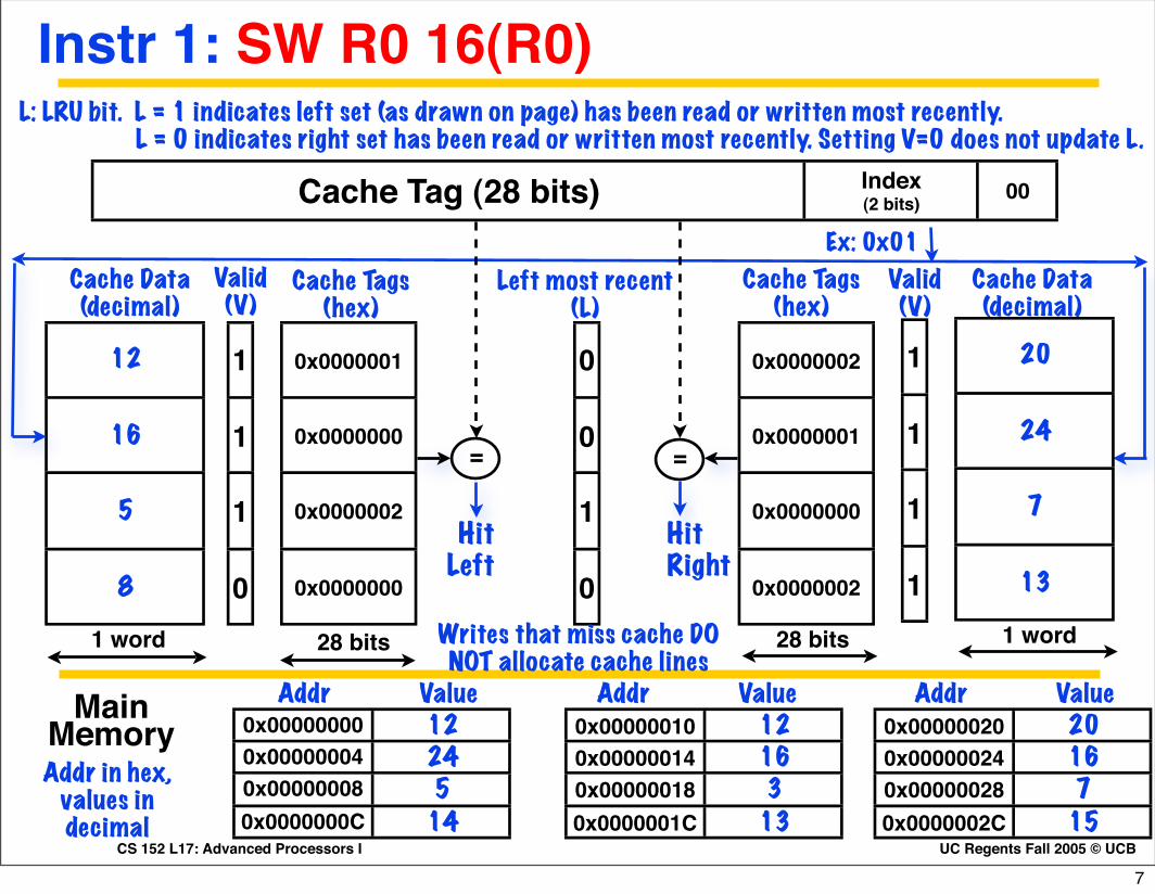
Q2. Write-back, no write on allocate cache
Cache Tag (28 bits) Index(2 bits) 00
1
1
1
0
Cache Data(decimal)
12
16
5
8
0x0000001
0x0000000
0x0000002
0x0000000
Cache Tags(hex)
Valid(V)
Ex: 0x01
=
HitRight
=
HitLeft
1 word
0
0
1
0
Left most recent(L)
1 word 28 bits28 bits
L: LRU bit. L = 1 indicates left set (as drawn on page) has been read or written most recently. L = 0 indicates right set has been read or written most recently. Setting V=0 does not update L.
0x0000002
0x0000001
0x0000000
0x0000002
1
1
1
1
20
24
7
13
0x00000000 120x00000004 240x00000008 50x0000000C 14
Addr Value Addr Value Addr ValueMain MemoryAddr in hex,
values in decimal
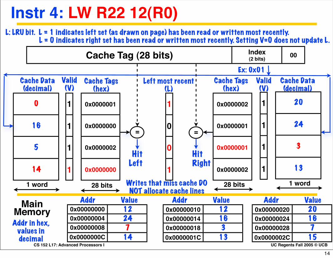
Writes that miss cache DO NOT allocate cache lines
0x00000010 120x00000014 160x00000018 30x0000001C 13
0x00000020 200x00000024 160x00000028 70x0000002C 15
Cache Data(decimal)
Cache Tags(hex)
Valid(V)
6
UC Regents Fall 2005 © UCBCS 152 L17: Advanced Processors I
Cache Tag (28 bits) Index(2 bits) 00
1
1
1
0
Cache Data(decimal)
12
16
5
8
0x0000001
0x0000000
0x0000002
0x0000000
Cache Tags(hex)
Valid(V)
Ex: 0x01
=
HitRight
=
HitLeft
1 word
0
0
1
0
Left most recent(L)
1 word 28 bits28 bits
L: LRU bit. L = 1 indicates left set (as drawn on page) has been read or written most recently. L = 0 indicates right set has been read or written most recently. Setting V=0 does not update L.
0x0000002
0x0000001
0x0000000
0x0000002
1
1
1
1
20
24
7
13
0x00000000 120x00000004 240x00000008 50x0000000C 14
Addr Value Addr Value Addr ValueMain MemoryAddr in hex,
values in decimal
Writes that miss cache DO NOT allocate cache lines
0x00000010 120x00000014 160x00000018 30x0000001C 13
0x00000020 200x00000024 160x00000028 70x0000002C 15
Cache Data(decimal)
Cache Tags(hex)
Valid(V)
Instr 1: SW R0 16(R0)
7

UC Regents Fall 2005 © UCBCS 152 L17: Advanced Processors I
Instr 1: SW R0 16(R0)
Cache Tag (28 bits) Index(2 bits) 00
1
1
1
0
Cache Data(decimal)
0
16
5
8
0x0000001
0x0000000
0x0000002
0x0000000
Cache Tags(hex)
Valid(V)
Ex: 0x01
=
HitRight
=
HitLeft
1 word
1
0
1
0
Left most recent(L)
1 word 28 bits28 bits
L: LRU bit. L = 1 indicates left set (as drawn on page) has been read or written most recently. L = 0 indicates right set has been read or written most recently. Setting V=0 does not update L.
0x0000002
0x0000001
0x0000000
0x0000002
1
1
1
1
20
24
7
13
0x00000000 120x00000004 240x00000008 50x0000000C 14
Addr Value Addr Value Addr ValueMain MemoryAddr in hex,
values in decimal
Writes that miss cache DO NOT allocate cache lines
0x00000010 120x00000014 160x00000018 30x0000001C 13
0x00000020 200x00000024 160x00000028 70x0000002C 15
Cache Data(decimal)
Cache Tags(hex)
Valid(V)
8

UC Regents Fall 2005 © UCBCS 152 L17: Advanced Processors I
Cache Tag (28 bits) Index(2 bits) 00
1
1
1
0
Cache Data(decimal)
0
16
5
8
0x0000001
0x0000000
0x0000002
0x0000000
Cache Tags(hex)
Valid(V)
Ex: 0x01
=
HitRight
=
HitLeft
1 word
1
0
1
0
Left most recent(L)
1 word 28 bits28 bits
L: LRU bit. L = 1 indicates left set (as drawn on page) has been read or written most recently. L = 0 indicates right set has been read or written most recently. Setting V=0 does not update L.
0x0000002
0x0000001
0x0000000
0x0000002
1
1
1
1
20
24
7
13
0x00000000 120x00000004 240x00000008 50x0000000C 14
Addr Value Addr Value Addr ValueMain MemoryAddr in hex,
values in decimal
Writes that miss cache DO NOT allocate cache lines
0x00000010 120x00000014 160x00000018 30x0000001C 13
0x00000020 200x00000024 160x00000028 70x0000002C 15
Cache Data(decimal)
Cache Tags(hex)
Valid(V)
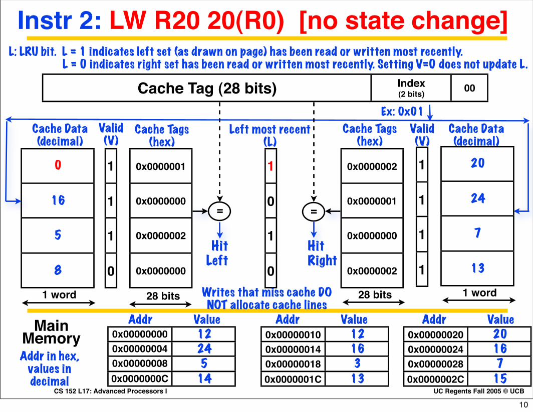
Instr 2: LW R20 20(R0)
9
UC Regents Fall 2005 © UCBCS 152 L17: Advanced Processors I
Instr 2: LW R20 20(R0) [no state change]
Cache Tag (28 bits) Index(2 bits) 00
1
1
1
0
Cache Data(decimal)
0
16
5
8
0x0000001
0x0000000
0x0000002
0x0000000
Cache Tags(hex)
Valid(V)
Ex: 0x01
=
HitRight
=
HitLeft
1 word
1
0
1
0
Left most recent(L)
1 word 28 bits28 bits
L: LRU bit. L = 1 indicates left set (as drawn on page) has been read or written most recently. L = 0 indicates right set has been read or written most recently. Setting V=0 does not update L.
0x0000002
0x0000001
0x0000000
0x0000002
1
1
1
1
20
24
7
13
0x00000000 120x00000004 240x00000008 50x0000000C 14
Addr Value Addr Value Addr ValueMain MemoryAddr in hex,
values in decimal
Writes that miss cache DO NOT allocate cache lines
0x00000010 120x00000014 160x00000018 30x0000001C 13
0x00000020 200x00000024 160x00000028 70x0000002C 15
Cache Data(decimal)
Cache Tags(hex)
Valid(V)
10
UC Regents Fall 2005 © UCBCS 152 L17: Advanced Processors I
Cache Tag (28 bits) Index(2 bits) 00
1
1
1
0
Cache Data(decimal)
0
16
5
8
0x0000001
0x0000000
0x0000002
0x0000000
Cache Tags(hex)
Valid(V)
Ex: 0x01
=
HitRight
=
HitLeft
1 word
1
0
1
0
Left most recent(L)
1 word 28 bits28 bits
L: LRU bit. L = 1 indicates left set (as drawn on page) has been read or written most recently. L = 0 indicates right set has been read or written most recently. Setting V=0 does not update L.
0x0000002
0x0000001
0x0000000
0x0000002
1
1
1
1
20
24
7
13
0x00000000 120x00000004 240x00000008 50x0000000C 14
Addr Value Addr Value Addr ValueMain MemoryAddr in hex,
values in decimal
Writes that miss cache DO NOT allocate cache lines
0x00000010 120x00000014 160x00000018 30x0000001C 13
0x00000020 200x00000024 160x00000028 70x0000002C 15
Cache Data(decimal)
Cache Tags(hex)
Valid(V)
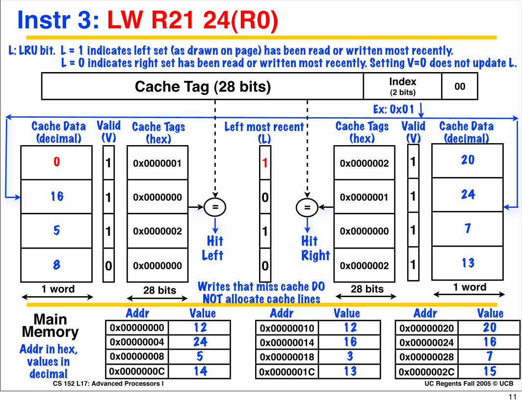
Instr 3: LW R21 24(R0)
11

UC Regents Fall 2005 © UCBCS 152 L17: Advanced Processors I
Instr 3: LW R21 24(R0)
Cache Tag (28 bits) Index(2 bits) 00
1
1
1
0
Cache Data(decimal)
0
16
5
8
0x0000001
0x0000000
0x0000002
0x0000000
Cache Tags(hex)
Valid(V)
Ex: 0x01
=
HitRight
=
HitLeft
1 word
1
0
0
0
Left most recent(L)
1 word 28 bits28 bits
L: LRU bit. L = 1 indicates left set (as drawn on page) has been read or written most recently. L = 0 indicates right set has been read or written most recently. Setting V=0 does not update L.
0x0000002
0x0000001
0x0000001
0x0000002
1
1
1
1
20
24
3
13
0x00000000 120x00000004 240x00000008 70x0000000C 14
Addr Value Addr Value Addr ValueMain MemoryAddr in hex,
values in decimal
Writes that miss cache DO NOT allocate cache lines
0x00000010 120x00000014 160x00000018 30x0000001C 13
0x00000020 200x00000024 160x00000028 70x0000002C 15
Cache Data(decimal)
Cache Tags(hex)
Valid(V)
12

UC Regents Fall 2005 © UCBCS 152 L17: Advanced Processors I
Cache Tag (28 bits) Index(2 bits) 00
1
1
1
0
Cache Data(decimal)
0
16
5
8
0x0000001
0x0000000
0x0000002
0x0000000
Cache Tags(hex)
Valid(V)
Ex: 0x01
=
HitRight
=
HitLeft
1 word
1
0
0
0
Left most recent(L)
1 word 28 bits28 bits
L: LRU bit. L = 1 indicates left set (as drawn on page) has been read or written most recently. L = 0 indicates right set has been read or written most recently. Setting V=0 does not update L.
0x0000002
0x0000001
0x0000001
0x0000002
1
1
1
1
20
24
3
13
0x00000000 120x00000004 240x00000008 70x0000000C 14
Addr Value Addr Value Addr ValueMain MemoryAddr in hex,
values in decimal
Writes that miss cache DO NOT allocate cache lines
0x00000010 120x00000014 160x00000018 30x0000001C 13
0x00000020 200x00000024 160x00000028 70x0000002C 15
Cache Data(decimal)
Cache Tags(hex)
Valid(V)
Instr 4: LW R22 12(R0)
13
UC Regents Fall 2005 © UCBCS 152 L17: Advanced Processors I
Instr 4: LW R22 12(R0)
Cache Tag (28 bits) Index(2 bits) 00
1
1
1
1
Cache Data(decimal)
0
16
5
14
0x0000001
0x0000000
0x0000002
0x0000000
Cache Tags(hex)
Valid(V)
Ex: 0x01
=
HitRight
=
HitLeft
1 word
1
0
0
1
Left most recent(L)
1 word 28 bits28 bits
L: LRU bit. L = 1 indicates left set (as drawn on page) has been read or written most recently. L = 0 indicates right set has been read or written most recently. Setting V=0 does not update L.
0x0000002
0x0000001
0x0000001
0x0000002
1
1
1
1
20
24
3
13
0x00000000 120x00000004 240x00000008 70x0000000C 14
Addr Value Addr Value Addr ValueMain MemoryAddr in hex,
values in decimal
Writes that miss cache DO NOT allocate cache lines
0x00000010 120x00000014 160x00000018 30x0000001C 13
0x00000020 200x00000024 160x00000028 70x0000002C 15
Cache Data(decimal)
Cache Tags(hex)
Valid(V)
14
UC Regents Fall 2005 © UCBCS 152 L17: Advanced Processors I
Cache Tag (28 bits) Index(2 bits) 00
1
1
1
1
Cache Data(decimal)
0
16
5
14
0x0000001
0x0000000
0x0000002
0x0000000
Cache Tags(hex)
Valid(V)
Ex: 0x01
=
HitRight
=
HitLeft
1 word
1
0
0
1
Left most recent(L)
1 word 28 bits28 bits
L: LRU bit. L = 1 indicates left set (as drawn on page) has been read or written most recently. L = 0 indicates right set has been read or written most recently. Setting V=0 does not update L.
0x0000002
0x0000001
0x0000001
0x0000002
1
1
1
1
20
24
3
13
0x00000000 120x00000004 240x00000008 70x0000000C 14
Addr Value Addr Value Addr ValueMain MemoryAddr in hex,
values in decimal
Writes that miss cache DO NOT allocate cache lines
0x00000010 120x00000014 160x00000018 30x0000001C 13
0x00000020 200x00000024 160x00000028 70x0000002C 15
Cache Data(decimal)
Cache Tags(hex)
Valid(V)
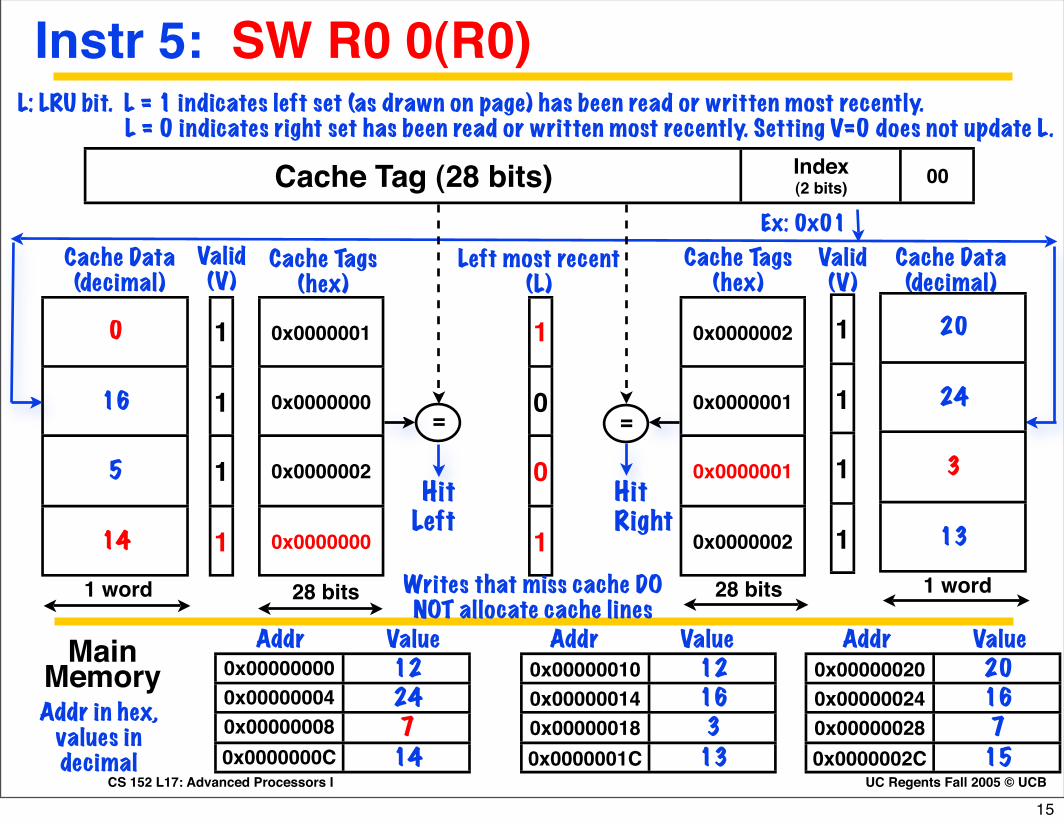
Instr 5: SW R0 0(R0)
15
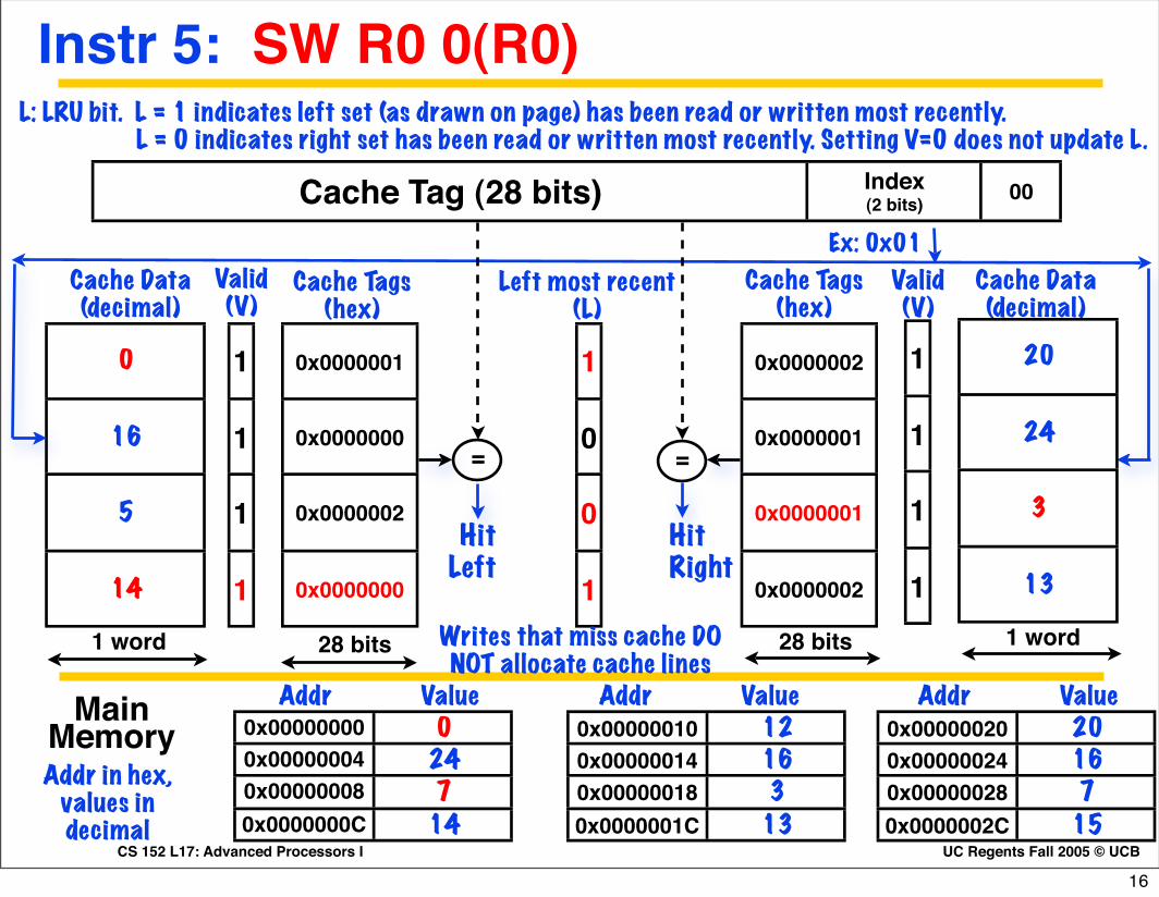
UC Regents Fall 2005 © UCBCS 152 L17: Advanced Processors I
Instr 5: SW R0 0(R0)
Cache Tag (28 bits) Index(2 bits) 00
1
1
1
1
Cache Data(decimal)
0
16
5
14
0x0000001
0x0000000
0x0000002
0x0000000
Cache Tags(hex)
Valid(V)
Ex: 0x01
=
HitRight
=
HitLeft
1 word
1
0
0
1
Left most recent(L)
1 word 28 bits28 bits
L: LRU bit. L = 1 indicates left set (as drawn on page) has been read or written most recently. L = 0 indicates right set has been read or written most recently. Setting V=0 does not update L.
0x0000002
0x0000001
0x0000001
0x0000002
1
1
1
1
20
24
3
13
0x00000000 00x00000004 240x00000008 70x0000000C 14
Addr Value Addr Value Addr ValueMain MemoryAddr in hex,
values in decimal
Writes that miss cache DO NOT allocate cache lines
0x00000010 120x00000014 160x00000018 30x0000001C 13
0x00000020 200x00000024 160x00000028 70x0000002C 15
Cache Data(decimal)
Cache Tags(hex)
Valid(V)
16

UC Regents Fall 2005 © UCBCS 152 L17: Advanced Processors I
Q2. Answer (red numbers from last slide)
Cache Tag (28 bits) Index(2 bits) 00
1
Cache Data(decimal)
0
14 0x0000000
Cache Tags(hex)
Valid(V)
Ex: 0x01
=
HitRight
=
HitLeft
1 word
1
0
1
Left most recent(L)
1 word 28 bits28 bits
L: LRU bit. L = 1 indicates left set (as drawn on page) has been read or written most recently. L = 0 indicates right set has been read or written most recently. Setting V=0 does not update L.
0x0000001 3
0x00000000 00x000000040x00000008 70x0000000C
Addr Value Addr Value Addr ValueMain MemoryAddr in hex,
values in decimal
Writes that miss cache DO NOT allocate cache lines
0x000000100x000000140x000000180x0000001C
0x000000200x000000240x000000280x0000002C
Cache Data(decimal)
Cache Tags(hex)
Valid(V)
17
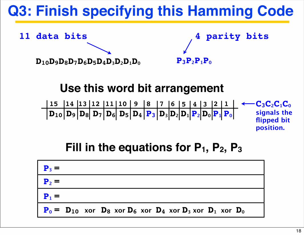
Q3: Finish specifying this Hamming Code
P3P₂P₁P₀
4 parity bits
Fill in the equations for P1, P2, P3
P₀ = D10 xor D8 xor D6 xor D4 xor D₃ xor D₁ xor D₀ P₁ =
P₂ =
11 data bits
D10D9D8D7D6D5D4D₃D₂D₁D₀
P3 =
D10 D9 D8 D7 D6 D5 D4 P3 D₃ D₂ D₁ P₂ D₀ P₁ P₀
Use this word bit arrangement15 14 13 12 11 10 9 8 7 6 5 4 3 2 1 C3C₂C₁C₀
signals the flipped bit position.
18
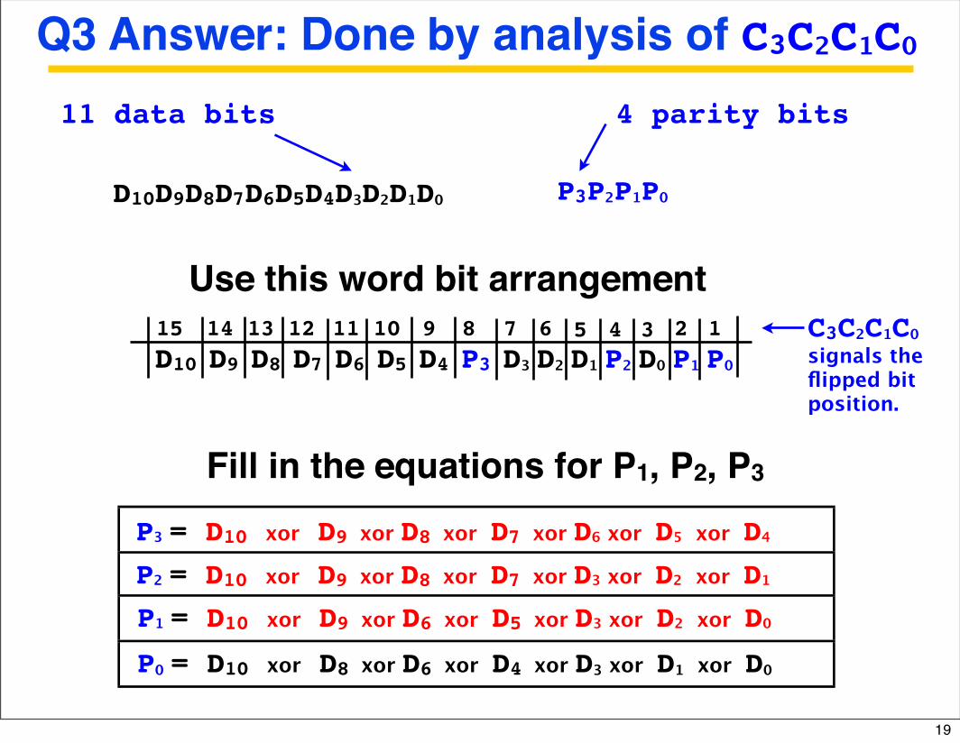
Q3 Answer: Done by analysis of C3C₂C₁C₀
P3P₂P₁P₀
4 parity bits
Fill in the equations for P1, P2, P3
P₀ = D10 xor D8 xor D6 xor D4 xor D₃ xor D₁ xor D₀
11 data bits
D10D9D8D7D6D5D4D₃D₂D₁D₀
D10 D9 D8 D7 D6 D5 D4 P3 D₃ D₂ D₁ P₂ D₀ P₁ P₀
Use this word bit arrangement15 14 13 12 11 10 9 8 7 6 5 4 3 2 1
P1 = D10 xor D9 xor D6 xor D5 xor D3 xor D2 xor D0
P3 = D10 xor D9 xor D8 xor D7 xor D6 xor D5 xor D4
P2 = D10 xor D9 xor D8 xor D7 xor D3 xor D2 xor D1
C3C₂C₁C₀signals the flipped bit position.
19
UC Regents Fall 2005 © UCBCS 152 L17: Advanced Processors I
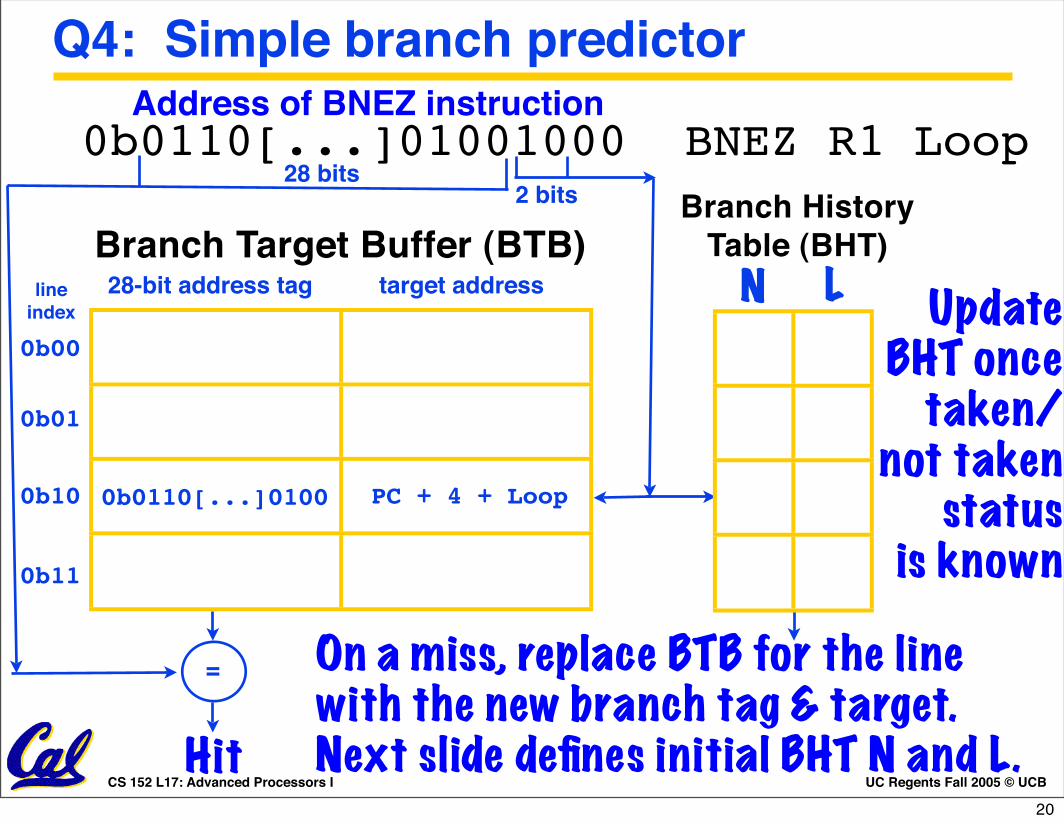
Q4: Simple branch predictor
0b0110[...]01001000 BNEZ R1 Loop
Update BHT once
taken/not taken
status is known
On a miss, replace BTB for the line with the new branch tag & target. Next slide defines initial BHT N and L.
Branch History Table (BHT)
2 bits
target addressBranch Target Buffer (BTB)
PC + 4 + Loop
28-bit address tag
0b0110[...]0100
Address of BNEZ instruction
=
Hit
28 bits
N L0b00
0b01
0b10
0b11
line index
20

Simple (”2-bit”) Branch History State
D Q D Q
“N bit”Prediction for Next branch
(1 = take, 0 = not take)
“L bit”Was Last prediction correct?
(1 = yes, 0 = no)
N L
old N old L branch new N new L0 0 not taken 0 10 0 taken 1 10 1 not taken 0 10 1 taken 0 01 0 not taken 0 11 0 taken 1 11 1 not taken 1 01 1 taken 1 1
When replacing the tag value for a line, initialize branch history state to (N = 1, L = 1) (for taken branches) or to (N = 0, L = 1) (for “not taken” branches).
21
target address
PC + 4 + Lab6
28-bit address tag
0b00
0b01
0b10
0b11
line indexN L
PC + 4 + Lab1
PC + 4 + Lab4
PC + 4 + Lab8
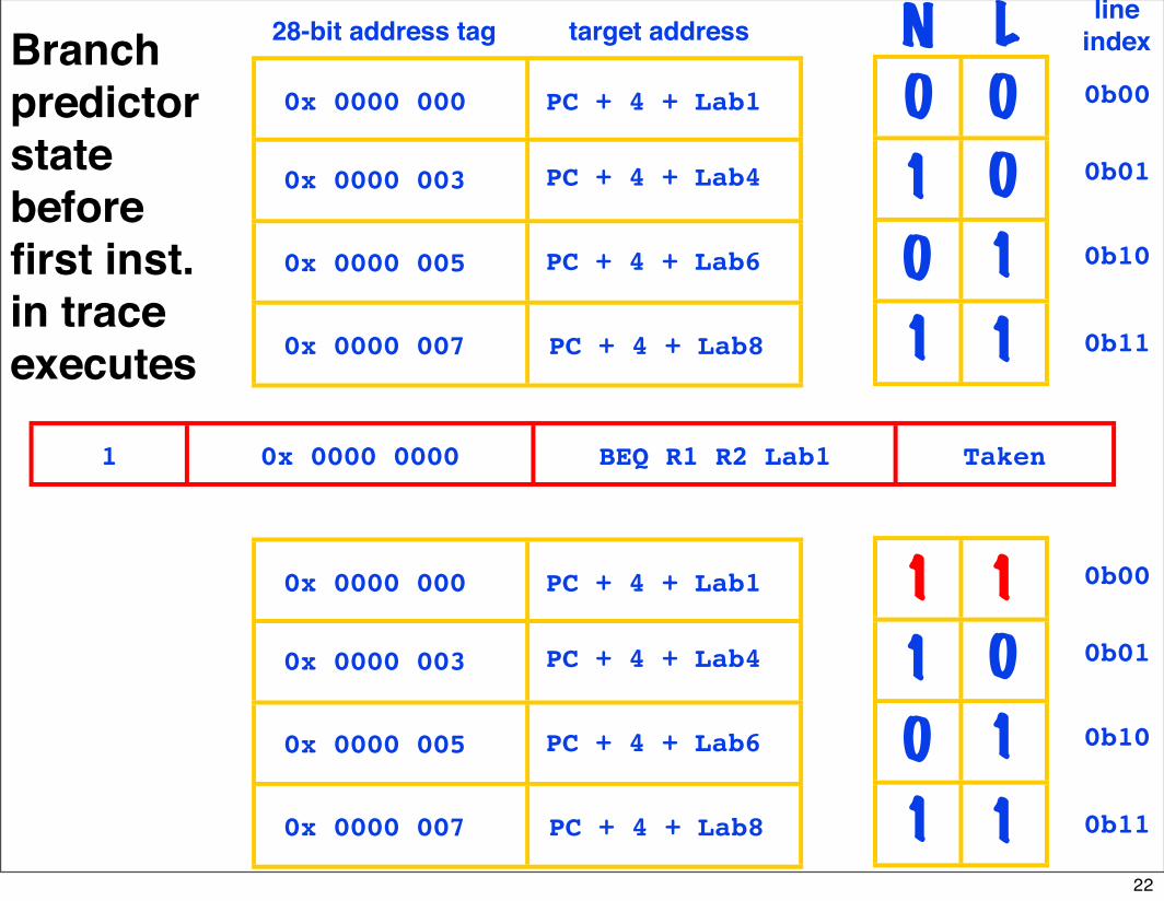
Branch predictor state before first inst. in trace executes
0x 0000 000
0x 0000 003
0x 0000 005
0x 0000 007
0 0
01
0 1
11
PC + 4 + Lab6
0b00
0b01
0b10
0b11
PC + 4 + Lab1
PC + 4 + Lab4
PC + 4 + Lab8
0x 0000 000
0x 0000 003
0x 0000 005
0x 0000 007
1 1
01
0 1
11
1 0x 0000 0000 BEQ R1 R2 Lab1 Taken
22
PC + 4 + Lab6
0b00
0b01
0b10
0b11
PC + 4 + Lab1
PC + 4 + Lab4
PC + 4 + Lab8
0x 0000 000
0x 0000 003
0x 0000 005
0x 0000 007
1 1
10
0 1
11
PC + 4 + Lab6
0b00
0b01
0b10
0b11
PC + 4 + Lab1
PC + 4 + Lab4
PC + 4 + Lab8
0x 0000 000
0x 0000 003
0x 0000 005
0x 0000 007
1 1
01
0 1
11
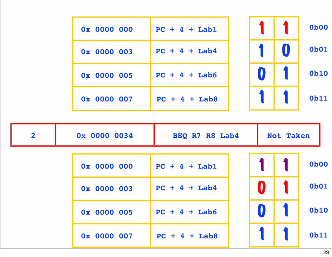
2 0x 0000 0034 BEQ R7 R8 Lab4 Not Taken
23

PC + 4 + Lab6
0b00
0b01
0b10
0b11
PC + 4 + Lab1
PC + 4 + Lab4
PC + 4 + Lab7
0x 0000 000
0x 0000 003
0x 0000 005
0x 0000 006
1 1
10
0 1
10
PC + 4 + Lab6
0b00
0b01
0b10
0b11
PC + 4 + Lab1
PC + 4 + Lab4
PC + 4 + Lab8
0x 0000 000
0x 0000 003
0x 0000 005
0x 0000 007
1 1
10
0 1
11
3 0x 0000 006C BEQ R13 R14 Lab7 Not Taken
24
PC + 4 + Lab6
0b00
0b01
0b10
0b11
PC + 4 + Lab1
PC + 4 + Lab4
PC + 4 + Lab7
0x 0000 000
0x 0000 003
0x 0000 005
0x 0000 006
1 1
10
0 0
10
PC + 4 + Lab6
0b00
0b01
0b10
0b11
PC + 4 + Lab1
PC + 4 + Lab4
PC + 4 + Lab7
0x 0000 000
0x 0000 003
0x 0000 005
0x 0000 006
1 1
10
0 1
10
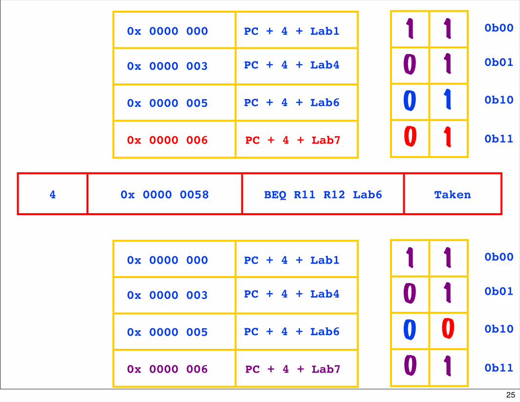
4 0x 0000 0058 BEQ R11 R12 Lab6 Taken
25
PC + 4 + Lab6
0b00
0b01
0b10
0b11
PC + 4 + Lab3
PC + 4 + Lab4
PC + 4 + Lab7
0x 0000 002
0x 0000 003
0x 0000 005
0x 0000 006
1 1
10
0 0
10
PC + 4 + Lab6
0b00
0b01
0b10
0b11
PC + 4 + Lab1
PC + 4 + Lab4
PC + 4 + Lab7
0x 0000 000
0x 0000 003
0x 0000 005
0x 0000 006
1 1
10
0 0
10
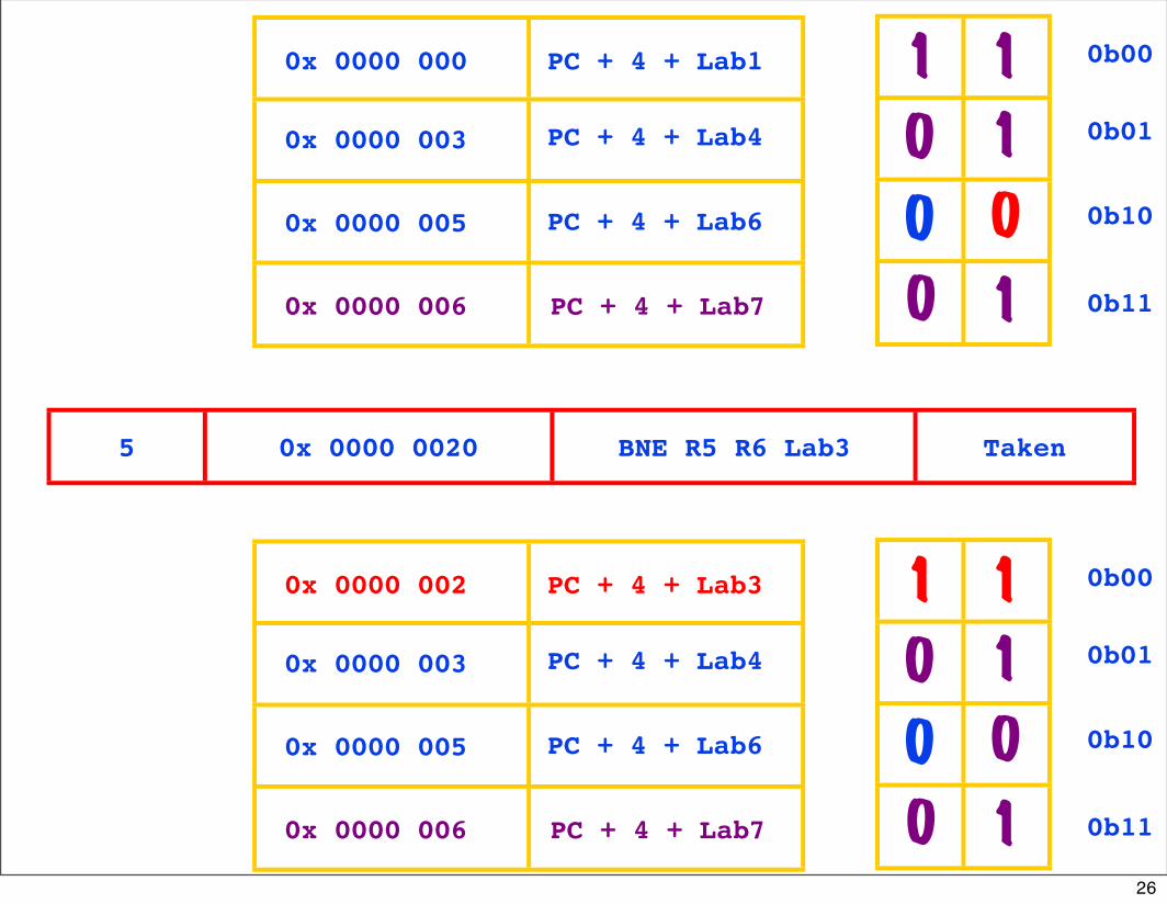
5 0x 0000 0020 BNE R5 R6 Lab3 Taken
26
PC + 4 + Lab6
0b00
0b01
0b10
0b11
PC + 4 + Lab3
PC + 4 + Lab4
PC + 4 + Lab7
0x 0000 002
0x 0000 003
0x 0000 005
0x 0000 006
1 1
00
0 0
10
PC + 4 + Lab6
0b00
0b01
0b10
0b11
PC + 4 + Lab3
PC + 4 + Lab4
PC + 4 + Lab7
0x 0000 002
0x 0000 003
0x 0000 005
0x 0000 006
1 1
10
0 0
10
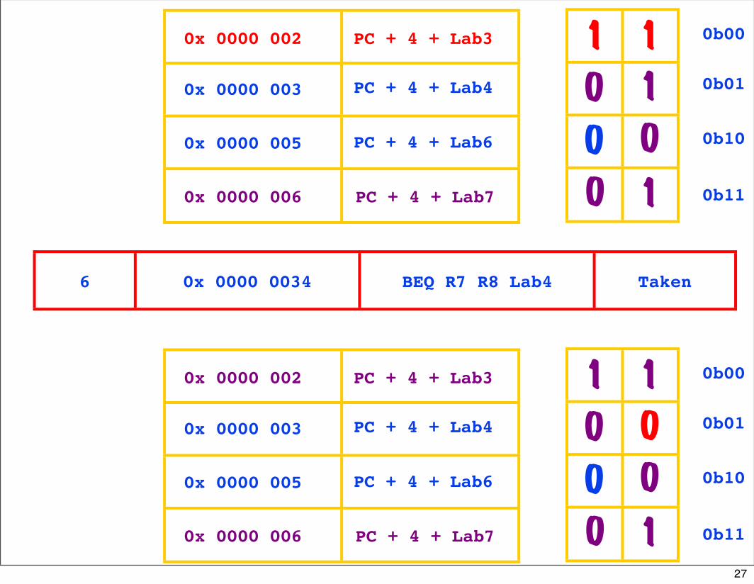
6 0x 0000 0034 BEQ R7 R8 Lab4 Taken
27

PC + 4 + Lab6
0b00
0b01
0b10
0b11
PC + 4 + Lab3
PC + 4 + Lab4
PC + 4 + Lab7
0x 0000 002
0x 0000 003
0x 0000 005
0x 0000 006
1 1
00
0 0
10
PC + 4 + Lab6
0b00
0b01
0b10
0b11
PC + 4 + Lab3
PC + 4 + Lab4
PC + 4 + Lab7
0x 0000 002
0x 0000 003
0x 0000 005
0x 0000 006
1 1
00
0 0
10
7 0x 0000 006C BEQ R13 R14 Lab7 Not Taken
Q4 Answer:Branch predictor state after 7 branches complete
28
UC Regents Fall 2005 © UCBCS 152 L22: Routers
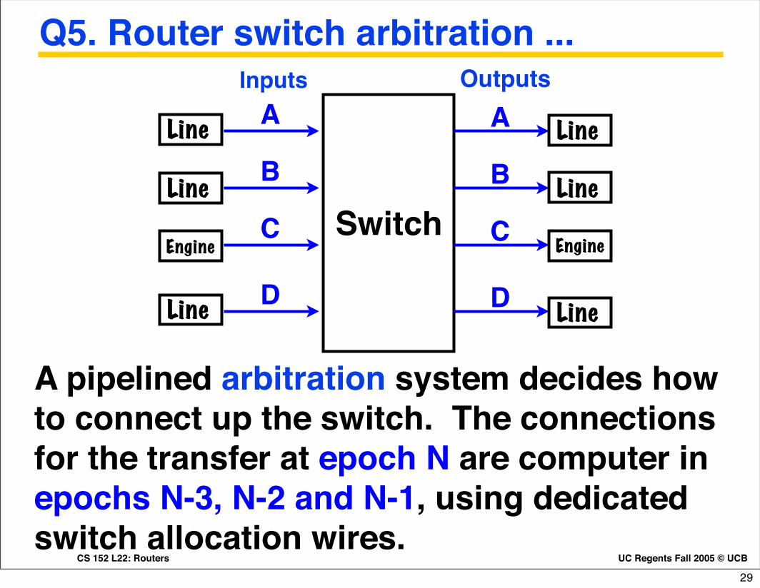
Q5. Router switch arbitration ...
Switch
Line
Line
Engine
Line
Engine
Line
Line
A pipelined arbitration system decides how to connect up the switch. The connections for the transfer at epoch N are computer in epochs N-3, N-2 and N-1, using dedicated switch allocation wires.
A
B
C
D
A
B
C
D Line
Inputs Outputs
29
UC Regents Fall 2005 © UCBCS 152 L22: Routers
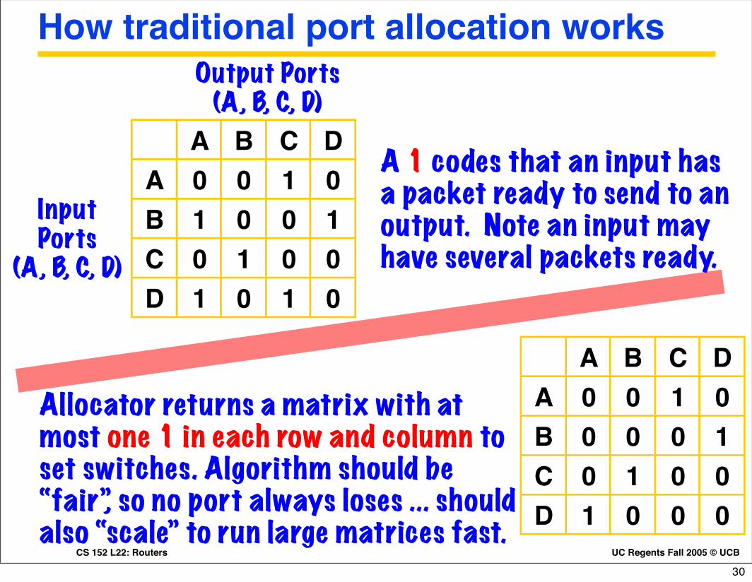
How traditional port allocation works
A B C DA 0 0 1 0B 1 0 0 1C 0 1 0 0D 1 0 1 0
Input Ports
(A, B, C, D)
Output Ports (A, B, C, D)
A 1 codes that an input has a packet ready to send to an output. Note an input may have several packets ready.
A B C DA 0 0 1 0B 0 0 0 1C 0 1 0 0D 1 0 0 0
Allocator returns a matrix with at most one 1 in each row and column to set switches. Algorithm should be “fair”, so no port always loses ... should also “scale” to run large matrices fast.
30
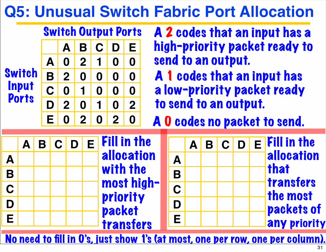
A B C D EA 0 2 1 0 0B 2 0 0 0 0C 0 1 0 0 0D 2 0 1 0 2E 0 2 0 2 0
SwitchInput Ports
Switch Output Ports A 2 codes that an input has a high-priority packet ready to send to an output. A 1 codes that an input has a low-priority packet ready to send to an output.
A B C D EABCDE
A B C D EABCDE
Fill in the allocationwith the most high-priority packet transfers
Fill in the allocationthattransfers the most packets of any priority
Q5: Unusual Switch Fabric Port Allocation
No need to fill in 0’s, just show 1’s (at most, one per row, one per column).
A 0 codes no packet to send.
31

A B C D EA 0 2 1 0 0B 2 0 0 0 0C 0 1 0 0 0D 2 0 1 0 2E 0 2 0 2 0
SwitchInput Ports
Switch Output Ports A 2 codes that an input has a high-priority packet ready to send to an output. A 1 codes that an input has a low-priority packet ready to send to an output.
A B C D EA 1B 1CD 1E 1
A B C D EA 1B 1C 1D 1E 1
Fill in the allocationwith the most high-priority packet transfers
Fill in the allocationthattransfers the most packets of any priority
Q5 Answers: Port Allocations
No need to fill in 0’s, just show 1’s (at most, one per row, one per column).
A 0 codes no packet to send.
32
Q6. Reorder Buffer: Initial Values ...
Inst # Op U E #1 #2 #d P1 P2 Pd P1 value
P2 value
Pd value
7 ADD 0 01 02 03 1 1 0 10 20 318 SUB 0 03 01 13 0 1 0 32 10 409 ADD 0 02 13 04 1 0 0 20 -33 1210 SUB 0 13 04 05 0 0 0 32 32 -16
Physical register values
(in decimal)
Physicalregisternumbers
Validbits forvalues
111
01
00
Tail of List
Next instin programgoes here.
Head
ofList
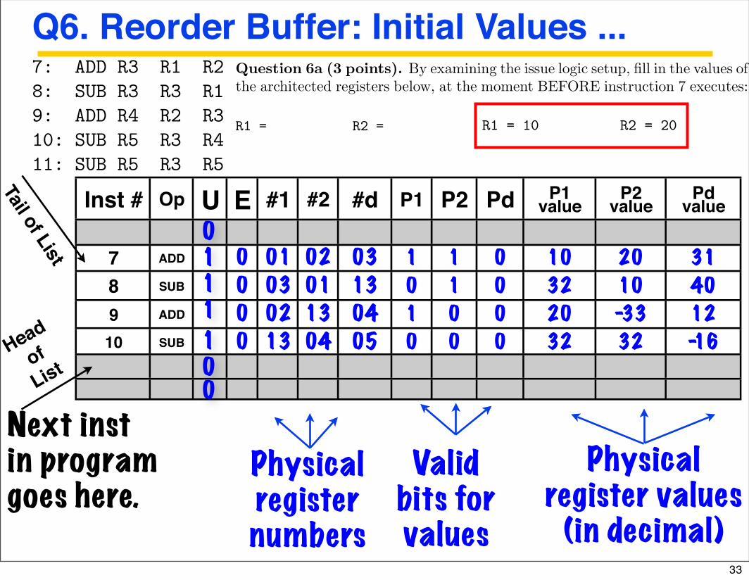
6 Reorder Bu!er Operation (22 points)
The following MIPS machine language program is to be run out an out of ordermachine
7: ADD R3 R1 R28: SUB R3 R3 R19: ADD R4 R2 R310: SUB R5 R3 R411: SUB R5 R3 R5
The top slide of the next page shows the initial state of the reorder bufferstructure shown in class, after issue logic has set up the buffer to execute in-structions 7, 8, 9, and 10.
Question 6a (3 points). By examining the issue logic setup, fill in the values ofthe architected registers below, at the moment BEFORE instruction 7 executes:
R1 = R2 =
Question 6b (16 points). Assume the execution engine executes instructions7-10. Fill in all columns for lines 7, 8, 9, and 10, showing the final state in thereorder buffer after all instructions have executed. Your answer should assumethat completion hardware has NOT removed any of the instructions from thebuffer. You only need to fill in state values that have been changed by theexecution engine.
6 Reorder Bu!er Operation (22 points)
The following MIPS machine language program is to be run out an out of ordermachine
7: ADD R3 R1 R28: SUB R3 R3 R19: ADD R4 R2 R310: SUB R5 R3 R411: SUB R5 R3 R5
The top slide of the next page shows the initial state of the reorder bu!erstructure shown in class, after issue logic has set up the bu!er to execute in-structions 7, 8, 9, and 10.
Question 6a (3 points). By examining the issue logic setup, fill in the values ofthe architected registers below, at the moment BEFORE instruction 7 executes:
R1 = R2 =
Question 6b (16 points). Assume the execution engine executes instructions7-10. Fill in all columns for lines 7, 8, 9, and 10, showing the final state in thereorder bu!er after all instructions have executed. Your answer should assumethat completion hardware has NOT removed any of the instructions from thebu!er. You only need to fill in state values that have been changed by theexecution engine.
6 Reorder Buffer Operation (22 points)
The following MIPS machine language program is to be run out an out of ordermachine
7: ADD R3 R1 R28: SUB R3 R3 R19: ADD R4 R2 R310: SUB R5 R3 R411: SUB R5 R3 R5
The top slide of the next page shows the initial state of the reorder bufferstructure shown in class, after issue logic has set up the buffer to execute in-structions 7, 8, 9, and 10.
Question 6a (3 points). By examining the issue logic setup, fill in the values ofthe architected registers below, at the moment BEFORE instruction 7 executes:
R1 = 10 R2 = 20
Question 6b (16 points). Assume the execution engine executes instructions7-10. Fill in all columns for lines 7, 8, 9, and 10, showing the final state in thereorder buffer after all instructions have executed. Your answer should assumethat completion hardware has NOT removed any of the instructions from thebuffer. You only need to fill in state values that have been changed by theexecution engine.
33
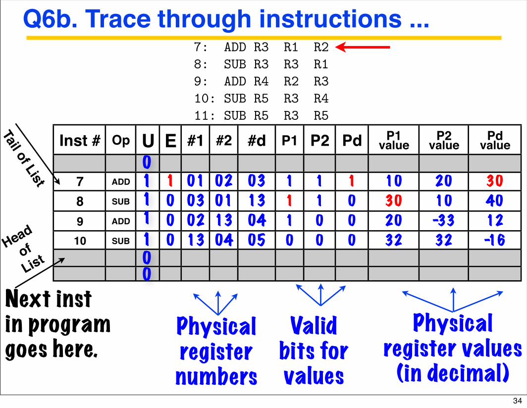
Q6b. Trace through instructions ...
Inst # Op U E #1 #2 #d P1 P2 Pd P1 value
P2 value
Pd value
7 ADD 1 01 02 03 1 1 1 10 20 308 SUB 0 03 01 13 1 1 0 30 10 409 ADD 0 02 13 04 1 0 0 20 -33 1210 SUB 0 13 04 05 0 0 0 32 32 -16
Physical register values
(in decimal)
Physicalregisternumbers
Validbits forvalues
111
01
00
Tail of List
Next instin programgoes here.
Head
ofList
6 Reorder Bu!er Operation (22 points)
The following MIPS machine language program is to be run out an out of ordermachine
7: ADD R3 R1 R28: SUB R3 R3 R19: ADD R4 R2 R310: SUB R5 R3 R411: SUB R5 R3 R5
The top slide of the next page shows the initial state of the reorder bufferstructure shown in class, after issue logic has set up the buffer to execute in-structions 7, 8, 9, and 10.
Question 6a (3 points). By examining the issue logic setup, fill in the values ofthe architected registers below, at the moment BEFORE instruction 7 executes:
R1 = R2 =
Question 6b (16 points). Assume the execution engine executes instructions7-10. Fill in all columns for lines 7, 8, 9, and 10, showing the final state in thereorder buffer after all instructions have executed. Your answer should assumethat completion hardware has NOT removed any of the instructions from thebuffer. You only need to fill in state values that have been changed by theexecution engine. 34
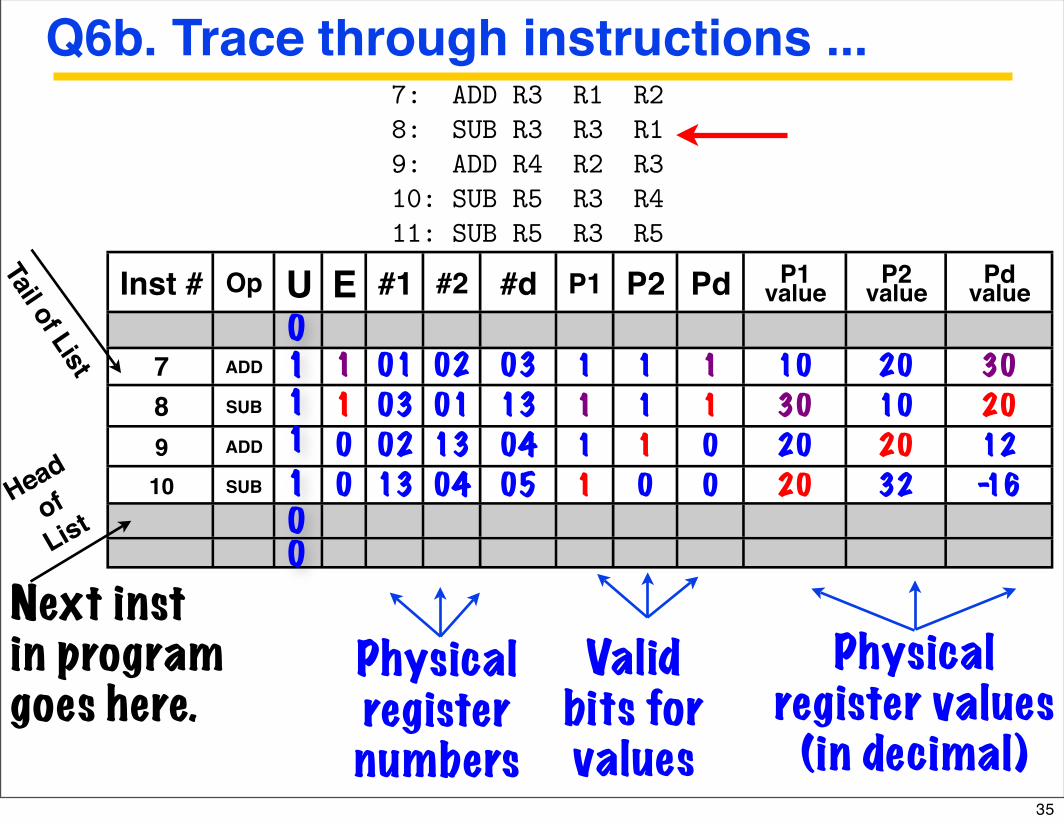
Q6b. Trace through instructions ...
Inst # Op U E #1 #2 #d P1 P2 Pd P1 value
P2 value
Pd value
7 ADD 1 01 02 03 1 1 1 10 20 308 SUB 1 03 01 13 1 1 1 30 10 209 ADD 0 02 13 04 1 1 0 20 20 1210 SUB 0 13 04 05 1 0 0 20 32 -16
Physical register values
(in decimal)
Physicalregisternumbers
Validbits forvalues
111
01
00
Tail of List
Next instin programgoes here.
Head
ofList
6 Reorder Bu!er Operation (22 points)
The following MIPS machine language program is to be run out an out of ordermachine
7: ADD R3 R1 R28: SUB R3 R3 R19: ADD R4 R2 R310: SUB R5 R3 R411: SUB R5 R3 R5
The top slide of the next page shows the initial state of the reorder bufferstructure shown in class, after issue logic has set up the buffer to execute in-structions 7, 8, 9, and 10.
Question 6a (3 points). By examining the issue logic setup, fill in the values ofthe architected registers below, at the moment BEFORE instruction 7 executes:
R1 = R2 =
Question 6b (16 points). Assume the execution engine executes instructions7-10. Fill in all columns for lines 7, 8, 9, and 10, showing the final state in thereorder buffer after all instructions have executed. Your answer should assumethat completion hardware has NOT removed any of the instructions from thebuffer. You only need to fill in state values that have been changed by theexecution engine. 35

Q6b. Trace through instructions ...
Inst # Op U E #1 #2 #d P1 P2 Pd P1 value
P2 value
Pd value
7 ADD 1 01 02 03 1 1 1 10 20 308 SUB 1 03 01 13 1 1 1 30 10 209 ADD 1 02 13 04 1 1 1 20 20 4010 SUB 0 13 04 05 1 1 0 20 40 -16
Physical register values
(in decimal)
Physicalregisternumbers
Validbits forvalues
111
01
00
Tail of List
Next instin programgoes here.
Head
ofList
6 Reorder Bu!er Operation (22 points)
The following MIPS machine language program is to be run out an out of ordermachine
7: ADD R3 R1 R28: SUB R3 R3 R19: ADD R4 R2 R310: SUB R5 R3 R411: SUB R5 R3 R5
The top slide of the next page shows the initial state of the reorder bufferstructure shown in class, after issue logic has set up the buffer to execute in-structions 7, 8, 9, and 10.
Question 6a (3 points). By examining the issue logic setup, fill in the values ofthe architected registers below, at the moment BEFORE instruction 7 executes:
R1 = R2 =
Question 6b (16 points). Assume the execution engine executes instructions7-10. Fill in all columns for lines 7, 8, 9, and 10, showing the final state in thereorder buffer after all instructions have executed. Your answer should assumethat completion hardware has NOT removed any of the instructions from thebuffer. You only need to fill in state values that have been changed by theexecution engine. 36
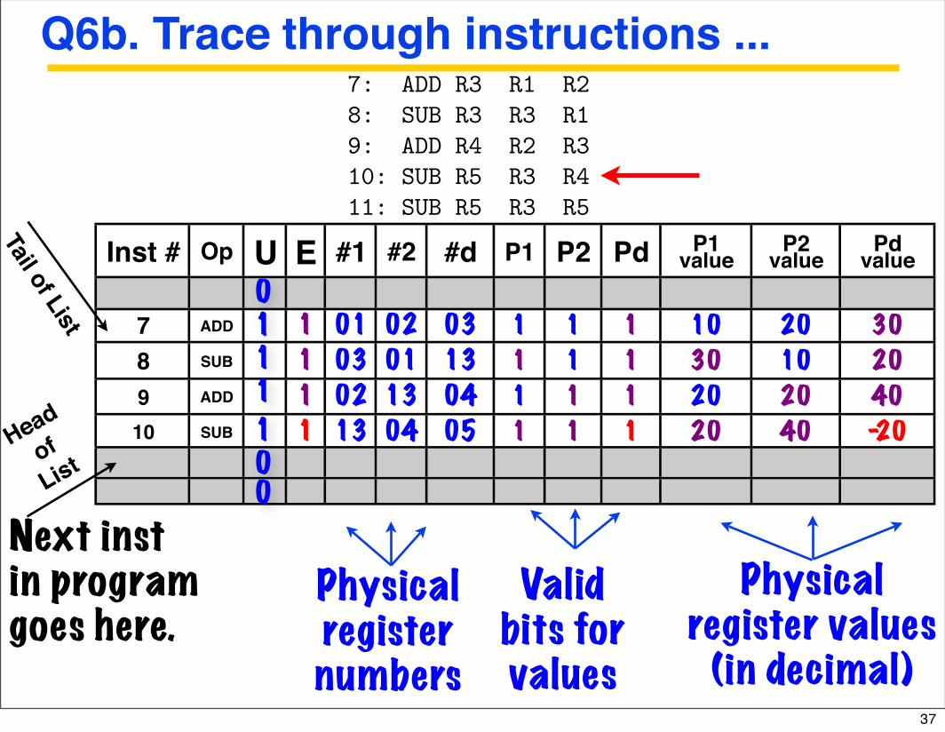
Q6b. Trace through instructions ...
Inst # Op U E #1 #2 #d P1 P2 Pd P1 value
P2 value
Pd value
7 ADD 1 01 02 03 1 1 1 10 20 308 SUB 1 03 01 13 1 1 1 30 10 209 ADD 1 02 13 04 1 1 1 20 20 4010 SUB 1 13 04 05 1 1 1 20 40 -20
Physical register values
(in decimal)
Physicalregisternumbers
Validbits forvalues
111
01
00
Tail of List
Next instin programgoes here.
Head
ofList
6 Reorder Bu!er Operation (22 points)
The following MIPS machine language program is to be run out an out of ordermachine
7: ADD R3 R1 R28: SUB R3 R3 R19: ADD R4 R2 R310: SUB R5 R3 R411: SUB R5 R3 R5
The top slide of the next page shows the initial state of the reorder bufferstructure shown in class, after issue logic has set up the buffer to execute in-structions 7, 8, 9, and 10.
Question 6a (3 points). By examining the issue logic setup, fill in the values ofthe architected registers below, at the moment BEFORE instruction 7 executes:
R1 = R2 =
Question 6b (16 points). Assume the execution engine executes instructions7-10. Fill in all columns for lines 7, 8, 9, and 10, showing the final state in thereorder buffer after all instructions have executed. Your answer should assumethat completion hardware has NOT removed any of the instructions from thebuffer. You only need to fill in state values that have been changed by theexecution engine. 37

Inst # Op U E #1 #2 #d P1 P2 Pd P1 value
P2 value
Pd value
7 ADD 1 01 02 03 1 1 1 10 20 308 SUB 1 03 01 13 1 1 1 30 10 209 ADD 1 02 13 04 1 1 1 20 20 4010 SUB 1 13 04 05 1 1 1 20 40 -2011 SUB 13 05 15 1 1 0 20 -20 -10
Physical register values
(in decimal)
Physicalregisternumbers
Validbits forvalues
111
01
10
Tail of List
Next instin programgoes here.
Head
ofList
6 Reorder Bu!er Operation (22 points)
The following MIPS machine language program is to be run out an out of ordermachine
7: ADD R3 R1 R28: SUB R3 R3 R19: ADD R4 R2 R310: SUB R5 R3 R411: SUB R5 R3 R5
The top slide of the next page shows the initial state of the reorder bufferstructure shown in class, after issue logic has set up the buffer to execute in-structions 7, 8, 9, and 10.
Question 6a (3 points). By examining the issue logic setup, fill in the values ofthe architected registers below, at the moment BEFORE instruction 7 executes:
R1 = R2 =
Question 6b (16 points). Assume the execution engine executes instructions7-10. Fill in all columns for lines 7, 8, 9, and 10, showing the final state in thereorder buffer after all instructions have executed. Your answer should assumethat completion hardware has NOT removed any of the instructions from thebuffer. You only need to fill in state values that have been changed by theexecution engine.
Q6c: Add Inst #11 line for: SUB R5 R3 R5
0
38

CS152 Midterm 2December 5th, 2006
Name:
“All the work is my own. I have no prior knowledge of the exam contents, aside from guidance from class staff. I will not share the contents with others in CS152 who have not taken it yet.”
Signature:Please write clearly, and put your name on each page. Please abide by word limits. Good luck!
Udam SainiJue SunJohn Lazzaro
1 13
2 12
3 13
4 12
5 13
6 12
7 13
8 12
Tot 100
# Points
SSID:
# of problems, points per problem subject to change !39
CS 152 L26: Mid-Term II Review UC Regents Fall 2006 © UCB
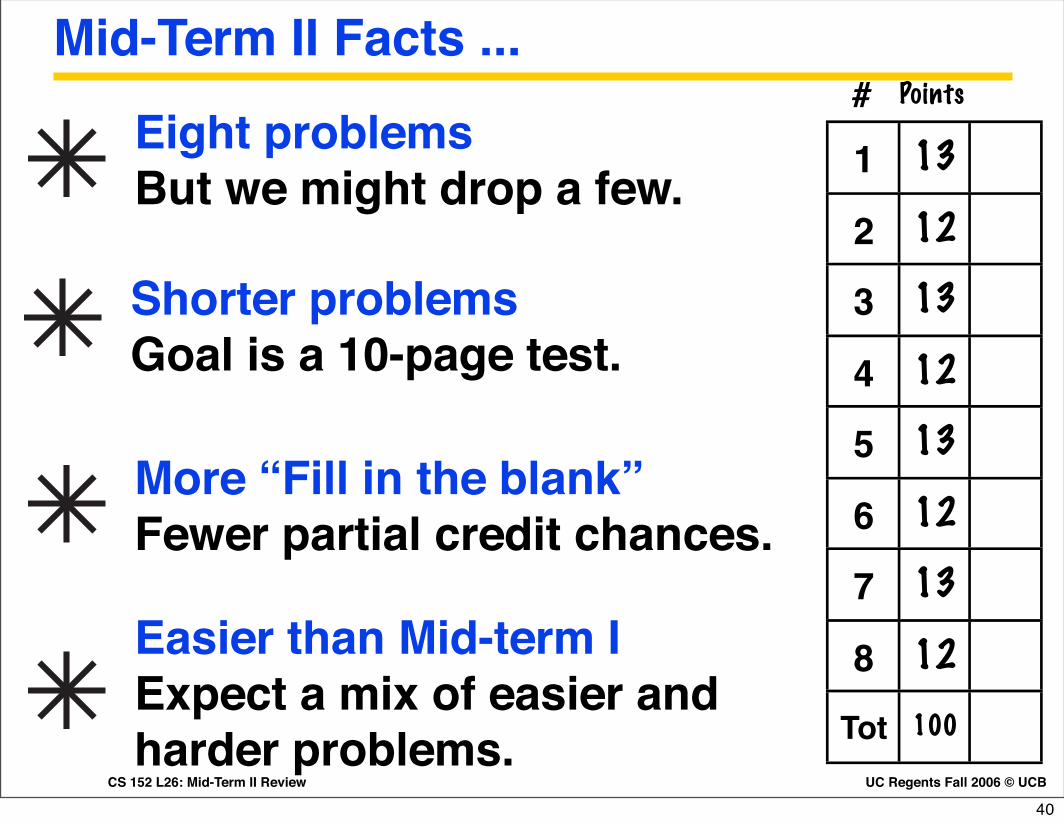
Mid-Term II Facts ...
Eight problems But we might drop a few.
Shorter problemsGoal is a 10-page test.
More “Fill in the blank”Fewer partial credit chances.
Easier than Mid-term IExpect a mix of easier and harder problems.
1 13
2 12
3 13
4 12
5 13
6 12
7 13
8 12
Tot 100
# Points
40
CS 152 L10: Midterm I Review UC Regents Fall 2006 © UCB
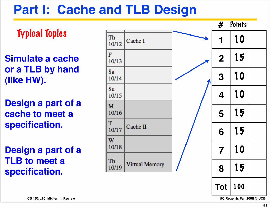
Part I: Cache and TLB Design
1 10
2 15
3 10
4 10
5 15
6 15
7 10
8 15
Tot 100
# Points
Design a part of a cache to meet a specification.
Simulate a cache or a TLB by hand (like HW).
Typical Topics
Design a part of a TLB to meet a specification.
41
CS 152 L10: Midterm I Review UC Regents Fall 2006 © UCB
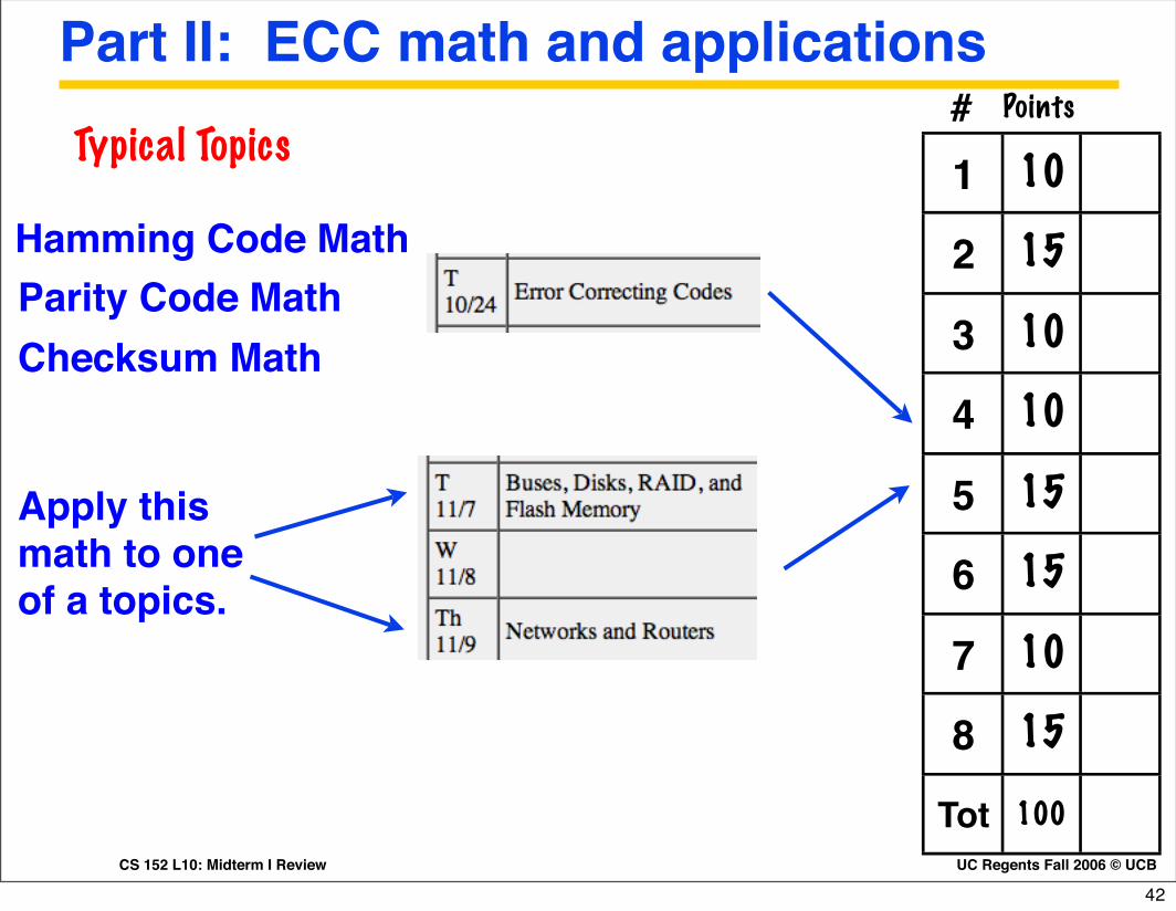
Part II: ECC math and applications
1 10
2 15
3 10
4 10
5 15
6 15
7 10
8 15
Tot 100
# Points
Apply this math to one of a topics.
Hamming Code Math
Typical Topics
Parity Code MathChecksum Math
42
CS 152 L10: Midterm I Review UC Regents Fall 2006 © UCB
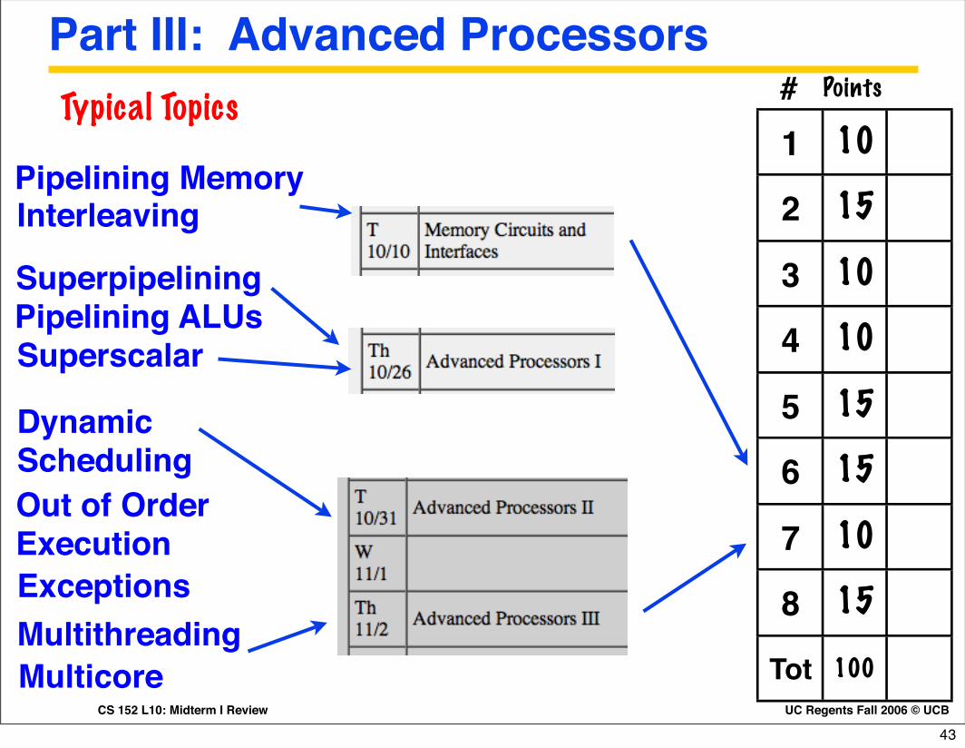
Part III: Advanced Processors
1 10
2 15
3 10
4 10
5 15
6 15
7 10
8 15
Tot 100
# Points
Superpipelining
Typical Topics
Pipelining ALUs
Pipelining Memory
Superscalar
Dynamic SchedulingOut of Order Execution
MultithreadingExceptions
Multicore
Interleaving
43
CS 152 L10: Midterm I Review UC Regents Fall 2006 © UCB
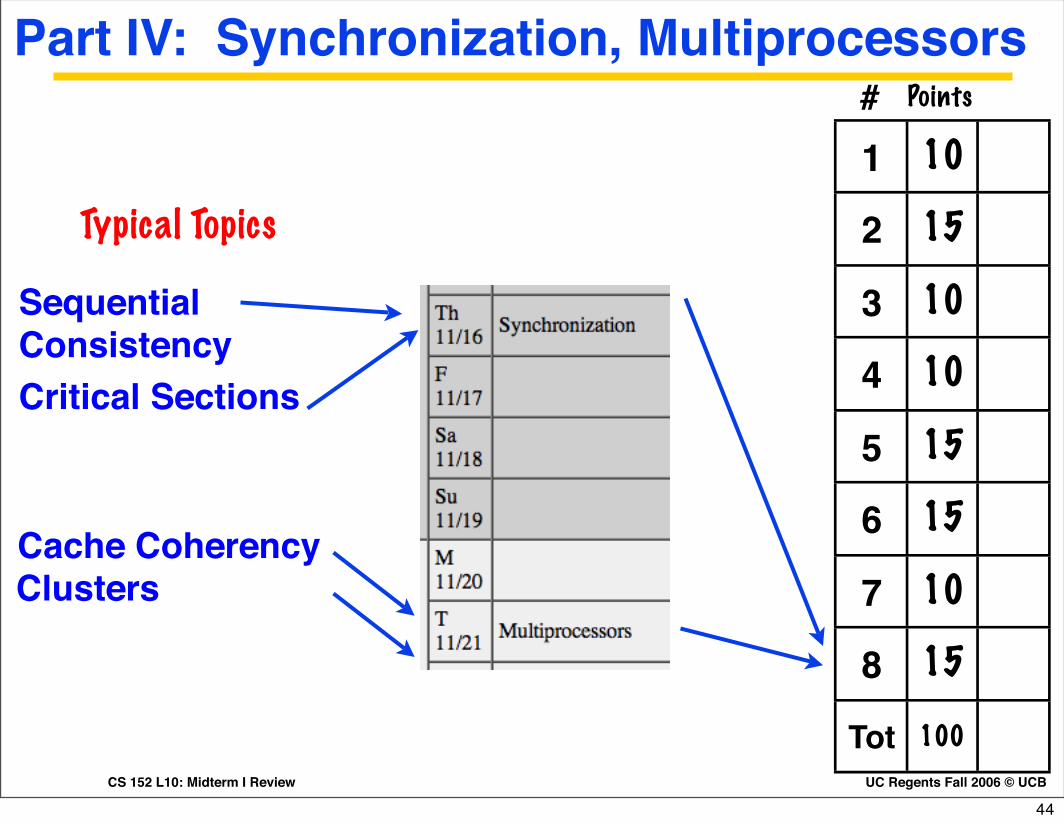
Part IV: Synchronization, Multiprocessors
1 10
2 15
3 10
4 10
5 15
6 15
7 10
8 15
Tot 100
# Points
Cache Coherency
Typical Topics
Clusters
Sequential ConsistencyCritical Sections
44

UC Regents Fall 2006 © UCBCS 152 L10: Midterm I Review
Administrivia: Mid-term I ...Starts at 6PM in 306 Soda. No class on Tuesday
Assigned seating: Look for your namecard on the desk.
Put bookbags and other personal belongings at the front of the room.
Put all electronic devices (cell phones, caclulators, PDAs, computers) at the front of the room.
45
UC Regents Fall 2006 © UCBCS 152 L10: Midterm I Review
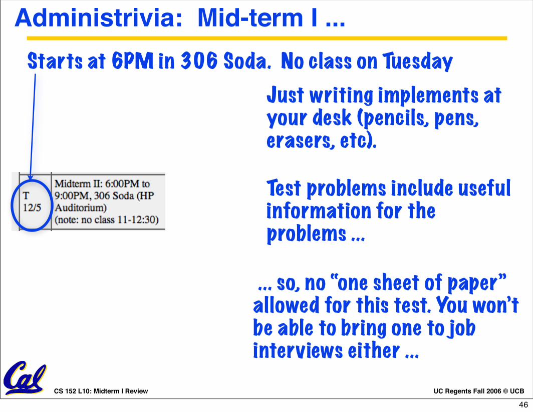
Administrivia: Mid-term I ...
Just writing implements at your desk (pencils, pens, erasers, etc).
Test problems include useful information for the problems ...
... so, no “one sheet of paper” allowed for this test. You won’t be able to bring one to job interviews either ...
Starts at 6PM in 306 Soda. No class on Tuesday
46

CS 152 L26: Mid-Term II Review UC Regents Fall 2006 © UCB
CS 152: Good luck on the mid-term!
No electronic devices, no notes,leave backpacks in front of class ...
Today: HKN, Mid-term II Review.Homework II due in class.
Thursday 12/7: Final presentations.Email slides to cs152-staff@cory by 11:50 PM.
Tuesday 12/5: Mid-term II, 6:00-9:00 PM, 306 Soda. No class 11-12:30 that day.
47