crystal unit (cryatal resonator) (pdf: 530kb) - murata
TRANSCRIPT
Crystal Units
P79E.pdfDec. 22,2020
EU RoHS Compliant
For r o ur
P79E.pdfDec. 22,2020
!Note • Please read rating and !CAUTION (for storage, operating, rating, soldering, mounting and handling) in this catalog to prevent smoking and/or burning, etc.• This catalog has only typical specifications. Therefore, please approve our product specifications or transact the approval sheet for product specifications before ordering.
Bluetoothr is a registered trademark or trademark
of Bluetooth SIG, Inc. in the United States and
other countries.
Contents
Please check the MURATA website (https://www.murata.com/) if you cannot find a part number in this catalog.
Product specifications are as of December 2020.
Selection Guide p2
Part Numbering p3
Measuring Circuit of Crystal Units p17
Crystal Units for Consumer and Industrial
Features, Applications p4
Appearance, Dimension p4
Series p4
Part Number List p5
Standard Land Pattern Dimensions p7
Notice p8
Packaging p10
Crystal Units for Automotive
Features, Applications p11
Appearance, Dimension p11
Series p12
Part Number List p12
Standard Land Pattern Dimensions p13
Notice p14
Packaging p16
1
2
1
2
P79E.pdfDec. 22,2020
!Note • Please read rating and !CAUTION (for storage, operating, rating, soldering, mounting and handling) in this catalog to prevent smoking and/or burning, etc.• This catalog has only typical specifications. Therefore, please approve our product specifications or transact the approval sheet for product specifications before ordering.
2
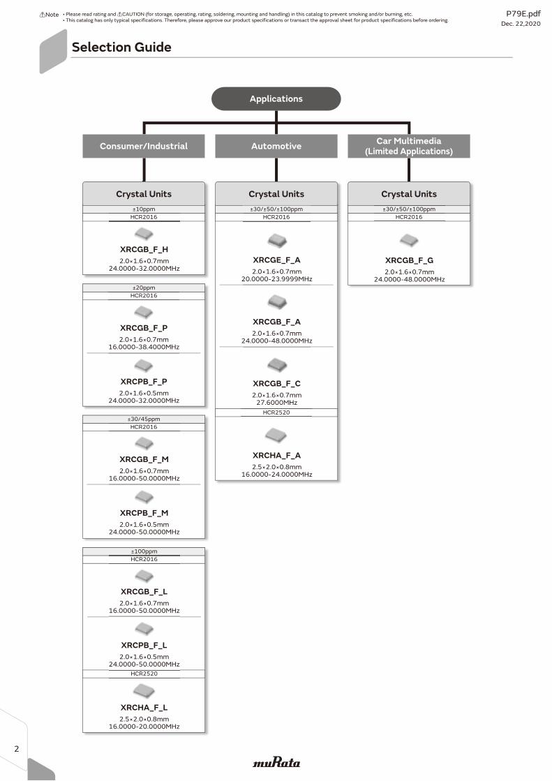
Selection Guide
±30/45ppm
HCR2016
Crystal Units
±100ppm
HCR2016
HCR2520
16.0000-20.0000MHz2.5×2.0×0.8mm
XRCHA_F_L
24.0000-50.0000MHz2.0×1.6×0.5mm
XRCPB_F_L
16.0000-50.0000MHz2.0×1.6×0.7mm
XRCGB_F_L
±30/±50/±100ppm
HCR2016
HCR2520
2.5×2.0×0.8mm16.0000-24.0000MHz
XRCHA_F_A
24.0000-48.0000MHz2.0×1.6×0.7mm
XRCGB_F_A
20.0000-23.9999MHz2.0×1.6×0.7mm
XRCGE_F_A
27.6000MHz2.0×1.6×0.7mm
XRCGB_F_C
Crystal Units
24.0000-50.0000MHz2.0×1.6×0.5mm
XRCPB_F_M
16.0000-50.0000MHz2.0×1.6×0.7mm
XRCGB_F_M
±10ppm
HCR2016
24.0000-32.0000MHz2.0×1.6×0.7mm
XRCGB_F_H
±20ppm
HCR2016
24.0000-32.0000MHz2.0×1.6×0.5mm
XRCPB_F_P
16.0000-38.4000MHz2.0×1.6×0.7mm
XRCGB_F_P
Consumer/Industrial Automotive
±30/±50/±100ppm
HCR2016
24.0000-48.0000MHz2.0×1.6×0.7mm
XRCGB_F_G
Crystal Units
Car Multimedia(Limited Applications)
Applications
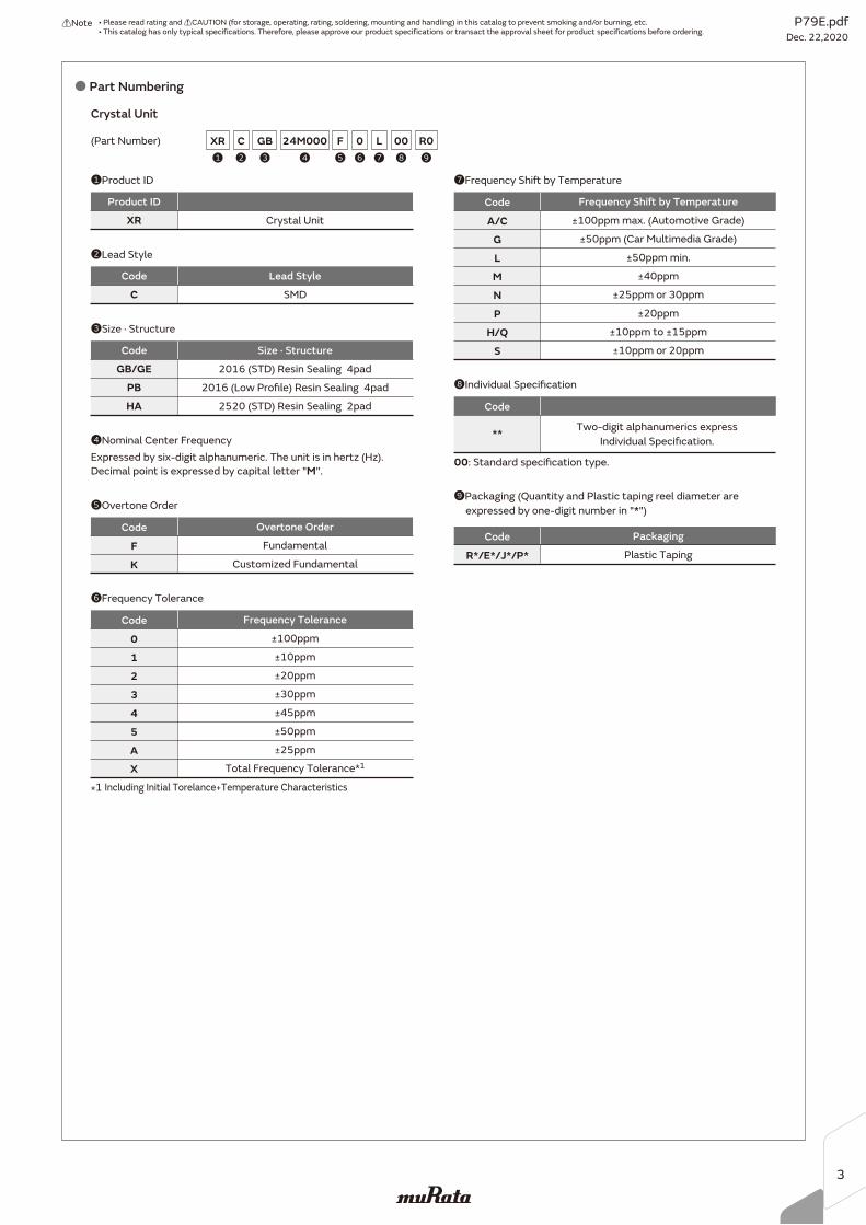
o Part Numbering
1Product ID
2Lead Style
4Nominal Center Frequency
8Individual Specification
Crystal Unit
XR Crystal Unit
C SMD
Product ID
Code Lead Style
(Part Number)
6Frequency Tolerance
Expressed by six-digit alphanumeric. The unit is in hertz (Hz).
Decimal point is expressed by capital letter "M".
*1 Including Initial Torelance+Temperature Characteristics
00: Standard specification type.
012345AX
Frequency ToleranceCode
±100ppm
±10ppm
±20ppm
±30ppm
±45ppm
±50ppm
±25ppm
Total Frequency Tolerance*1
7Frequency Shift by Temperature
A/CGLMNP
H/QS
Frequency Shift by TemperatureCode
±100ppm max. (Automotive Grade)
±50ppm (Car Multimedia Grade)
±50ppm min.
±40ppm
±25ppm or 30ppm
±20ppm
±10ppm to ±15ppm
±10ppm or 20ppm
**
Code
Two-digit alphanumerics express
Individual Specification.
5Overtone Order
FK
Overtone OrderCode
Fundamental
Customized Fundamental
8
003
GB2
C4
24M0009
R0XR1 7
L6
05
F
9Packaging (Quantity and Plastic taping reel diameter are
expressed by one-digit number in "*")
3Size · Structure
GB/GEPBHA
2016 (STD) Resin Sealing 4pad
2016 (Low Profile) Resin Sealing 4pad
2520 (STD) Resin Sealing 2pad
Code Size · Structure
R*/E*/J*/P*
PackagingCode
Plastic Taping
P79E.pdfDec. 22,2020
!Note • Please read rating and !CAUTION (for storage, operating, rating, soldering, mounting and handling) in this catalog to prevent smoking and/or burning, etc.• This catalog has only typical specifications. Therefore, please approve our product specifications or transact the approval sheet for product specifications before ordering.
3
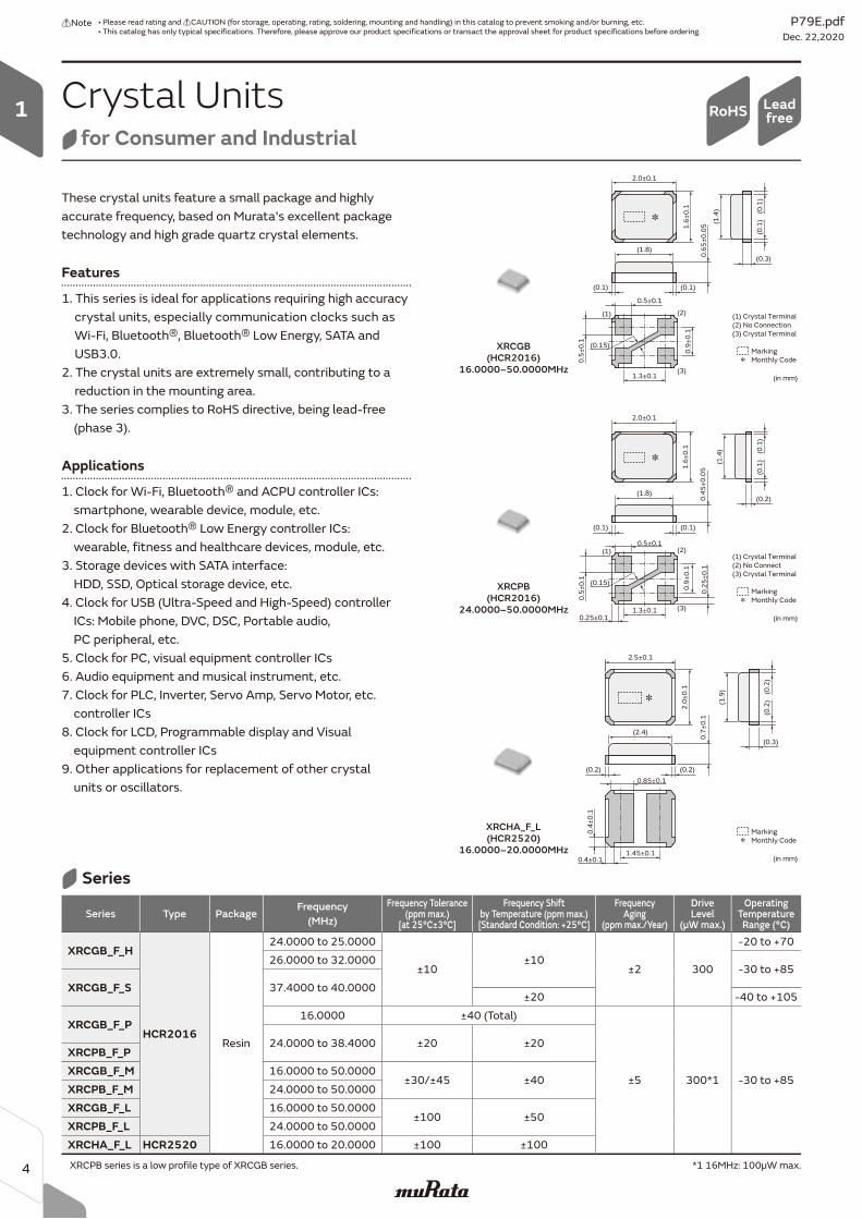
These crystal units feature a small package and highly accurate frequency, based on Murata's excellent package technology and high grade quartz crystal elements.
Features
1. This series is ideal for applications requiring high accuracy crystal units, especially communication clocks such as Wi-Fi, Bluetoothr, Bluetoothr Low Energy, SATA and USB3.0.
2. The crystal units are extremely small, contributing to a reduction in the mounting area.
3. The series complies to RoHS directive, being lead-free (phase 3).
Applications
1. Clock for Wi-Fi, Bluetoothr and ACPU controller ICs: smartphone, wearable device, module, etc.2. Clock for Bluetoothr Low Energy controller ICs: wearable, fitness and healthcare devices, module, etc.3. Storage devices with SATA interface: HDD, SSD, Optical storage device, etc.4. Clock for USB (Ultra-Speed and High-Speed) controller ICs: Mobile phone, DVC, DSC, Portable audio, PC peripheral, etc.5. Clock for PC, visual equipment controller ICs6. Audio equipment and musical instrument, etc.7. Clock for PLC, Inverter, Servo Amp, Servo Motor, etc. controller ICs8. Clock for LCD, Programmable display and Visual equipment controller ICs9. Other applications for replacement of other crystal units or oscillators.
(0.15)
(1)
(3)
(2)
Marking
Monthly Code
(in mm)
2.0±0.1
1.6
±0
.1 (0.1
)
(0.1)(0.1)
(1.4
)
(0.2)
0.5±0.1
0.4
5±
0.0
5
0.9
±0
.1
1.3±0.10.25±0.1
0.2
5±
0.1
0.5
±0
.1
(1.8)
(0.1
)
(1) Crystal Terminal
(2) No Connect
(3) Crystal Terminal
Marking
Monthly Code
(in mm)
2.0±0.1
1.6
±0
.1 (0.1
)
(0.1)(0.1)
(1.4
)
(0.3)
0.5±0.1
0.6
5±
0.0
5
0.9
±0
.1
1.3±0.1
0.5
±0
.1
(1.8)
(0.1
)
(1) Crystal Terminal
(2) No Connection
(3) Crystal Terminal
(0.15)
(1)
(3)
(2)
Crystal Unitsfor Consumer and Industrial
LeadfreeRoHS
XRCPB (HCR2016)
24.0000–50.0000MHz
XRCGB (HCR2016)
16.0000–50.0000MHz
Marking
Monthly Code
(in mm)
2.5±0.1
2.0
±0
.1 (0.2
)(0.2)(0.2)
(1.9
)
(0.3)
0.85±0.1
0.7
±0
.1
1.45±0.10.4±0.1
0.4
±0
.1
(2.4)
(0.2
)
XRCHA_F_L (HCR2520)
16.0000–20.0000MHz
Series Type PackageFrequency
(MHz)
Frequency Tolerance(ppm max.)
[at 25°C±3°C]
Frequency Shift by Temperature (ppm max.)[Standard Condition: +25°C]
FrequencyAging
(ppm max./Year)
DriveLevel
(μW max.)
OperatingTemperatureRange (°C)
XRCGB_F_H
HCR2016Resin
24.0000 to 25.0000
±10±10
±2 300
-20 to +7026.0000 to 32.0000
-30 to +85XRCGB_F_S 37.4000 to 40.0000
±20 -40 to +105
XRCGB_F_P16.0000 ±40 (Total)
±5 300*1 -30 to +85
24.0000 to 38.4000 ±20 ±20XRCPB_F_PXRCGB_F_M 16.0000 to 50.0000
±30/±45 ±40XRCPB_F_M 24.0000 to 50.0000XRCGB_F_L 16.0000 to 50.0000
±100 ±50XRCPB_F_L 24.0000 to 50.0000XRCHA_F_L HCR2520 16.0000 to 20.0000 ±100 ±100
XRCPB series is a low profile type of XRCGB series. *1 16MHz: 100µW max.
Series
P79E.pdfDec. 22,2020
!Note • Please read rating and !CAUTION (for storage, operating, rating, soldering, mounting and handling) in this catalog to prevent smoking and/or burning, etc.• This catalog has only typical specifications. Therefore, please approve our product specifications or transact the approval sheet for product specifications before ordering.
4
1
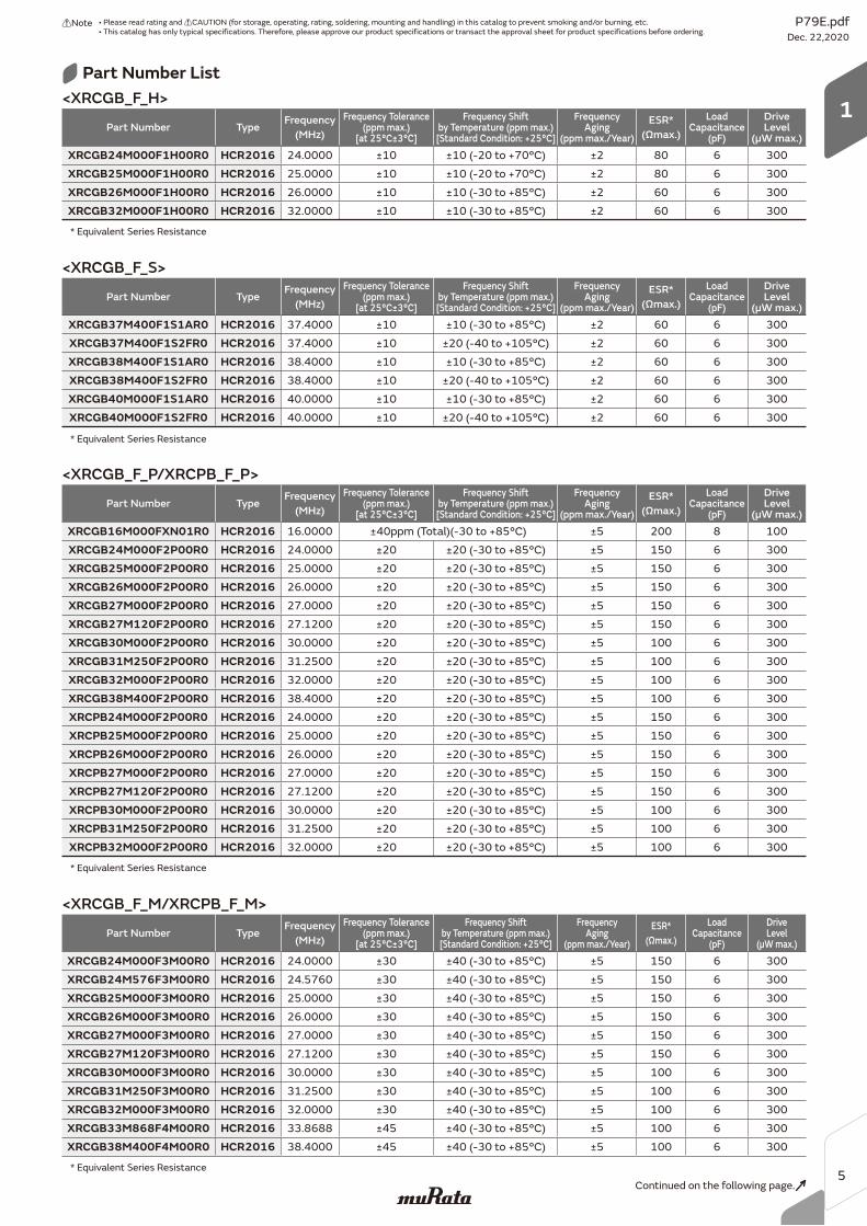
Part Number List
* Equivalent Series Resistance
Part Number TypeFrequency
(MHz)
Frequency Tolerance(ppm max.)
[at 25°C±3°C]
Frequency Shift by Temperature (ppm max.)[Standard Condition: +25°C]
FrequencyAging
(ppm max./Year)
ESR*
(Ωmax.)
LoadCapacitance
(pF)
DriveLevel
(μW max.)
XRCGB16M000FXN01R0 HCR2016 16.0000 ±40ppm (Total)(-30 to +85°C) ±5 200 8 100XRCGB24M000F2P00R0 HCR2016 24.0000 ±20 ±20 (-30 to +85°C) ±5 150 6 300XRCGB25M000F2P00R0 HCR2016 25.0000 ±20 ±20 (-30 to +85°C) ±5 150 6 300XRCGB26M000F2P00R0 HCR2016 26.0000 ±20 ±20 (-30 to +85°C) ±5 150 6 300XRCGB27M000F2P00R0 HCR2016 27.0000 ±20 ±20 (-30 to +85°C) ±5 150 6 300XRCGB27M120F2P00R0 HCR2016 27.1200 ±20 ±20 (-30 to +85°C) ±5 150 6 300XRCGB30M000F2P00R0 HCR2016 30.0000 ±20 ±20 (-30 to +85°C) ±5 100 6 300XRCGB31M250F2P00R0 HCR2016 31.2500 ±20 ±20 (-30 to +85°C) ±5 100 6 300XRCGB32M000F2P00R0 HCR2016 32.0000 ±20 ±20 (-30 to +85°C) ±5 100 6 300XRCGB38M400F2P00R0 HCR2016 38.4000 ±20 ±20 (-30 to +85°C) ±5 100 6 300XRCPB24M000F2P00R0 HCR2016 24.0000 ±20 ±20 (-30 to +85°C) ±5 150 6 300XRCPB25M000F2P00R0 HCR2016 25.0000 ±20 ±20 (-30 to +85°C) ±5 150 6 300XRCPB26M000F2P00R0 HCR2016 26.0000 ±20 ±20 (-30 to +85°C) ±5 150 6 300XRCPB27M000F2P00R0 HCR2016 27.0000 ±20 ±20 (-30 to +85°C) ±5 150 6 300XRCPB27M120F2P00R0 HCR2016 27.1200 ±20 ±20 (-30 to +85°C) ±5 150 6 300XRCPB30M000F2P00R0 HCR2016 30.0000 ±20 ±20 (-30 to +85°C) ±5 100 6 300XRCPB31M250F2P00R0 HCR2016 31.2500 ±20 ±20 (-30 to +85°C) ±5 100 6 300XRCPB32M000F2P00R0 HCR2016 32.0000 ±20 ±20 (-30 to +85°C) ±5 100 6 300
Part Number TypeFrequency
(MHz)
Frequency Tolerance(ppm max.)
[at 25°C±3°C]
Frequency Shift by Temperature (ppm max.)[Standard Condition: +25°C]
FrequencyAging
(ppm max./Year)
ESR*
(Ωmax.)
LoadCapacitance
(pF)
DriveLevel
(μW max.)
XRCGB37M400F1S1AR0 HCR2016 37.4000 ±10 ±10 (-30 to +85°C) ±2 60 6 300XRCGB37M400F1S2FR0 HCR2016 37.4000 ±10 ±20 (-40 to +105°C) ±2 60 6 300XRCGB38M400F1S1AR0 HCR2016 38.4000 ±10 ±10 (-30 to +85°C) ±2 60 6 300XRCGB38M400F1S2FR0 HCR2016 38.4000 ±10 ±20 (-40 to +105°C) ±2 60 6 300XRCGB40M000F1S1AR0 HCR2016 40.0000 ±10 ±10 (-30 to +85°C) ±2 60 6 300XRCGB40M000F1S2FR0 HCR2016 40.0000 ±10 ±20 (-40 to +105°C) ±2 60 6 300
<XRCGB_F_P/XRCPB_F_P>
<XRCGB_F_S>
<XRCGB_F_M/XRCPB_F_M>
* Equivalent Series Resistance
Part Number TypeFrequency
(MHz)
Frequency Tolerance(ppm max.)
[at 25°C±3°C]
Frequency Shift by Temperature (ppm max.)[Standard Condition: +25°C]
FrequencyAging
(ppm max./Year)
ESR*
(Ωmax.)
LoadCapacitance
(pF)
DriveLevel
(μW max.)
XRCGB24M000F1H00R0 HCR2016 24.0000 ±10 ±10 (-20 to +70°C) ±2 80 6 300XRCGB25M000F1H00R0 HCR2016 25.0000 ±10 ±10 (-20 to +70°C) ±2 80 6 300XRCGB26M000F1H00R0 HCR2016 26.0000 ±10 ±10 (-30 to +85°C) ±2 60 6 300XRCGB32M000F1H00R0 HCR2016 32.0000 ±10 ±10 (-30 to +85°C) ±2 60 6 300
<XRCGB_F_H>
* Equivalent Series Resistance
* Equivalent Series Resistance
Continued on the following page.
Part Number TypeFrequency
(MHz)
Frequency Tolerance(ppm max.)
[at 25°C±3°C]
Frequency Shift by Temperature (ppm max.)[Standard Condition: +25°C]
FrequencyAging
(ppm max./Year)
ESR*
(Ωmax.)
LoadCapacitance
(pF)
DriveLevel
(μW max.)
XRCGB24M000F3M00R0 HCR2016 24.0000 ±30 ±40 (-30 to +85°C) ±5 150 6 300XRCGB24M576F3M00R0 HCR2016 24.5760 ±30 ±40 (-30 to +85°C) ±5 150 6 300XRCGB25M000F3M00R0 HCR2016 25.0000 ±30 ±40 (-30 to +85°C) ±5 150 6 300XRCGB26M000F3M00R0 HCR2016 26.0000 ±30 ±40 (-30 to +85°C) ±5 150 6 300XRCGB27M000F3M00R0 HCR2016 27.0000 ±30 ±40 (-30 to +85°C) ±5 150 6 300XRCGB27M120F3M00R0 HCR2016 27.1200 ±30 ±40 (-30 to +85°C) ±5 150 6 300XRCGB30M000F3M00R0 HCR2016 30.0000 ±30 ±40 (-30 to +85°C) ±5 100 6 300XRCGB31M250F3M00R0 HCR2016 31.2500 ±30 ±40 (-30 to +85°C) ±5 100 6 300XRCGB32M000F3M00R0 HCR2016 32.0000 ±30 ±40 (-30 to +85°C) ±5 100 6 300XRCGB33M868F4M00R0 HCR2016 33.8688 ±45 ±40 (-30 to +85°C) ±5 100 6 300XRCGB38M400F4M00R0 HCR2016 38.4000 ±45 ±40 (-30 to +85°C) ±5 100 6 300
P79E.pdfDec. 22,2020
!Note • Please read rating and !CAUTION (for storage, operating, rating, soldering, mounting and handling) in this catalog to prevent smoking and/or burning, etc.• This catalog has only typical specifications. Therefore, please approve our product specifications or transact the approval sheet for product specifications before ordering.
5
1
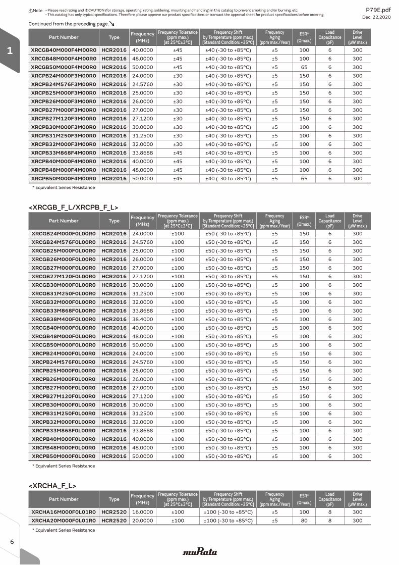
* Equivalent Series Resistance
Continued from the preceding page.
Part Number TypeFrequency
(MHz)
Frequency Tolerance(ppm max.)
[at 25°C±3°C]
Frequency Shift by Temperature (ppm max.)[Standard Condition: +25°C]
FrequencyAging
(ppm max./Year)
ESR*
(Ωmax.)
LoadCapacitance
(pF)
DriveLevel
(μW max.)
XRCGB40M000F4M00R0 HCR2016 40.0000 ±45 ±40 (-30 to +85°C) ±5 100 6 300XRCGB48M000F4M00R0 HCR2016 48.0000 ±45 ±40 (-30 to +85°C) ±5 100 6 300XRCGB50M000F4M00R0 HCR2016 50.0000 ±45 ±40 (-30 to +85°C) ±5 65 6 300XRCPB24M000F3M00R0 HCR2016 24.0000 ±30 ±40 (-30 to +85°C) ±5 150 6 300XRCPB24M576F3M00R0 HCR2016 24.5760 ±30 ±40 (-30 to +85°C) ±5 150 6 300XRCPB25M000F3M00R0 HCR2016 25.0000 ±30 ±40 (-30 to +85°C) ±5 150 6 300XRCPB26M000F3M00R0 HCR2016 26.0000 ±30 ±40 (-30 to +85°C) ±5 150 6 300XRCPB27M000F3M00R0 HCR2016 27.0000 ±30 ±40 (-30 to +85°C) ±5 150 6 300XRCPB27M120F3M00R0 HCR2016 27.1200 ±30 ±40 (-30 to +85°C) ±5 150 6 300XRCPB30M000F3M00R0 HCR2016 30.0000 ±30 ±40 (-30 to +85°C) ±5 100 6 300XRCPB31M250F3M00R0 HCR2016 31.2500 ±30 ±40 (-30 to +85°C) ±5 100 6 300XRCPB32M000F3M00R0 HCR2016 32.0000 ±30 ±40 (-30 to +85°C) ±5 100 6 300XRCPB33M868F4M00R0 HCR2016 33.8688 ±45 ±40 (-30 to +85°C) ±5 100 6 300XRCPB40M000F4M00R0 HCR2016 40.0000 ±45 ±40 (-30 to +85°C) ±5 100 6 300XRCPB48M000F4M00R0 HCR2016 48.0000 ±45 ±40 (-30 to +85°C) ±5 100 6 300XRCPB50M000F4M00R0 HCR2016 50.0000 ±45 ±40 (-30 to +85°C) ±5 65 6 300
Part Number TypeFrequency
(MHz)
Frequency Tolerance(ppm max.)
[at 25°C±3°C]
Frequency Shift by Temperature (ppm max.)[Standard Condition: +25°C]
FrequencyAging
(ppm max./Year)
ESR*
(Ωmax.)
LoadCapacitance
(pF)
DriveLevel
(μW max.)
XRCGB24M000F0L00R0 HCR2016 24.0000 ±100 ±50 (-30 to +85°C) ±5 150 6 300XRCGB24M576F0L00R0 HCR2016 24.5760 ±100 ±50 (-30 to +85°C) ±5 150 6 300XRCGB25M000F0L00R0 HCR2016 25.0000 ±100 ±50 (-30 to +85°C) ±5 150 6 300XRCGB26M000F0L00R0 HCR2016 26.0000 ±100 ±50 (-30 to +85°C) ±5 150 6 300XRCGB27M000F0L00R0 HCR2016 27.0000 ±100 ±50 (-30 to +85°C) ±5 150 6 300XRCGB27M120F0L00R0 HCR2016 27.1200 ±100 ±50 (-30 to +85°C) ±5 150 6 300XRCGB30M000F0L00R0 HCR2016 30.0000 ±100 ±50 (-30 to +85°C) ±5 100 6 300XRCGB31M250F0L00R0 HCR2016 31.2500 ±100 ±50 (-30 to +85°C) ±5 100 6 300XRCGB32M000F0L00R0 HCR2016 32.0000 ±100 ±50 (-30 to +85°C) ±5 100 6 300XRCGB33M868F0L00R0 HCR2016 33.8688 ±100 ±50 (-30 to +85°C) ±5 100 6 300XRCGB38M400F0L00R0 HCR2016 38.4000 ±100 ±50 (-30 to +85°C) ±5 100 6 300XRCGB40M000F0L00R0 HCR2016 40.0000 ±100 ±50 (-30 to +85°C) ±5 100 6 300XRCGB48M000F0L00R0 HCR2016 48.0000 ±100 ±50 (-30 to +85°C) ±5 100 6 300XRCGB50M000F0L00R0 HCR2016 50.0000 ±100 ±50 (-30 to +85°C) ±5 100 6 300XRCPB24M000F0L00R0 HCR2016 24.0000 ±100 ±50 (-30 to +85°C) ±5 150 6 300XRCPB24M576F0L00R0 HCR2016 24.5760 ±100 ±50 (-30 to +85°C) ±5 150 6 300XRCPB25M000F0L00R0 HCR2016 25.0000 ±100 ±50 (-30 to +85°C) ±5 150 6 300XRCPB26M000F0L00R0 HCR2016 26.0000 ±100 ±50 (-30 to +85°C) ±5 150 6 300XRCPB27M000F0L00R0 HCR2016 27.0000 ±100 ±50 (-30 to +85°C) ±5 150 6 300XRCPB27M120F0L00R0 HCR2016 27.1200 ±100 ±50 (-30 to +85°C) ±5 150 6 300XRCPB30M000F0L00R0 HCR2016 30.0000 ±100 ±50 (-30 to +85°C) ±5 100 6 300XRCPB31M250F0L00R0 HCR2016 31.2500 ±100 ±50 (-30 to +85°C) ±5 100 6 300XRCPB32M000F0L00R0 HCR2016 32.0000 ±100 ±50 (-30 to +85°C) ±5 100 6 300XRCPB33M868F0L00R0 HCR2016 33.8688 ±100 ±50 (-30 to +85°C) ±5 100 6 300XRCPB40M000F0L00R0 HCR2016 40.0000 ±100 ±50 (-30 to +85°C) ±5 100 6 300XRCPB48M000F0L00R0 HCR2016 48.0000 ±100 ±50 (-30 to +85°C) ±5 100 6 300XRCPB50M000F0L00R0 HCR2016 50.0000 ±100 ±50 (-30 to +85°C) ±5 100 6 300
* Equivalent Series Resistance
<XRCGB_F_L/XRCPB_F_L>
Part Number TypeFrequency
(MHz)
Frequency Tolerance(ppm max.)
[at 25°C±3°C]
Frequency Shift by Temperature (ppm max.)[Standard Condition: +25°C]
FrequencyAging
(ppm max./Year)
ESR*
(Ωmax.)
LoadCapacitance
(pF)
DriveLevel
(μW max.)
XRCHA16M000F0L01R0 HCR2520 16.0000 ±100 ±100 (-30 to +85°C) ±5 100 8 300XRCHA20M000F0L01R0 HCR2520 20.0000 ±100 ±100 (-30 to +85°C) ±5 80 8 300
* Equivalent Series Resistance
<XRCHA_F_L>
P79E.pdfDec. 22,2020
!Note • Please read rating and !CAUTION (for storage, operating, rating, soldering, mounting and handling) in this catalog to prevent smoking and/or burning, etc.• This catalog has only typical specifications. Therefore, please approve our product specifications or transact the approval sheet for product specifications before ordering.
6
1
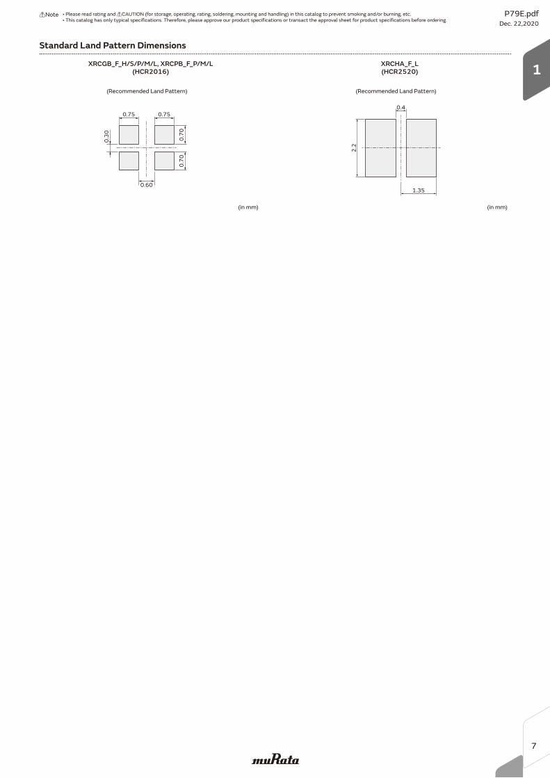
Standard Land Pattern Dimensions
(Recommended Land Pattern)
(in mm)
0.75
0.60
0.750.
30 0.70
0.70
(Recommended Land Pattern)
(in mm)
0.4
1.35
2.2
XRCGB_F_H/S/P/M/L, XRCPB_F_P/M/L(HCR2016)
XRCHA_F_L(HCR2520)
P79E.pdfDec. 22,2020
!Note • Please read rating and !CAUTION (for storage, operating, rating, soldering, mounting and handling) in this catalog to prevent smoking and/or burning, etc.• This catalog has only typical specifications. Therefore, please approve our product specifications or transact the approval sheet for product specifications before ordering.
7
1
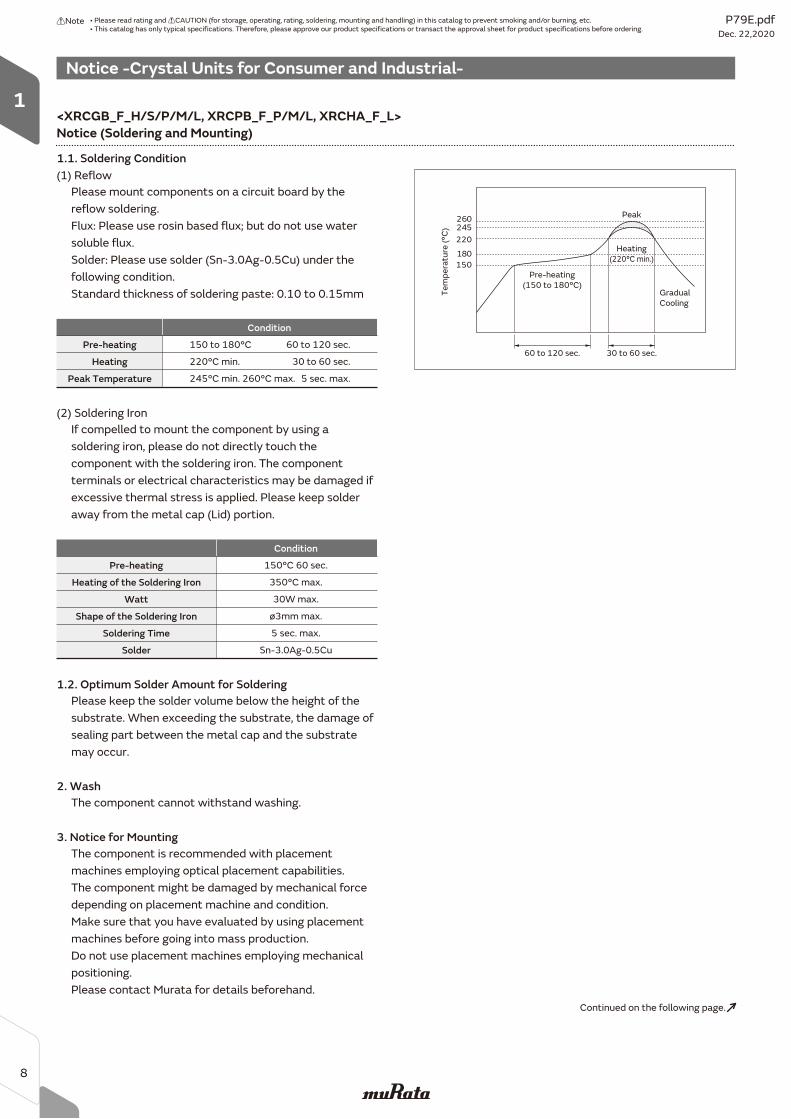
Notice -Crystal Units for Consumer and Industrial-
Please mount components on a circuit board by the
reflow soldering.
Flux: Please use rosin based flux; but do not use water
soluble flux.
Solder: Please use solder (Sn-3.0Ag-0.5Cu) under the
following condition.
Standard thickness of soldering paste: 0.10 to 0.15mm
1.1. Soldering Condition
Please keep the solder volume below the height of the
substrate. When exceeding the substrate, the damage of
sealing part between the metal cap and the substrate
may occur.
1.2. Optimum Solder Amount for Soldering
The component cannot withstand washing.
2. Wash
The component is recommended with placement
machines employing optical placement capabilities.
The component might be damaged by mechanical force
depending on placement machine and condition.
Make sure that you have evaluated by using placement
machines before going into mass production.
Do not use placement machines employing mechanical
positioning.
Please contact Murata for details beforehand.
3. Notice for Mounting
(1) Reflow
Pre-heating
Condition
150 to 180°C
Heating 220°C min.
Peak Temperature 245°C min. 260°C max.
60 to 120 sec.
30 to 60 sec.
5 sec. max.
If compelled to mount the component by using a
soldering iron, please do not directly touch the
component with the soldering iron. The component
terminals or electrical characteristics may be damaged if
excessive thermal stress is applied. Please keep solder
away from the metal cap (Lid) portion.
(2) Soldering Iron
Pre-heating
Condition
150°C 60 sec.
Heating of the Soldering Iron 350°C max.
Watt
Shape of the Soldering Iron
Soldering Time
Solder
30W max.
ø3mm max.
5 sec. max.
Sn-3.0Ag-0.5Cu
150
180
220
245260
Gradual
Cooling
Peak
Pre-heating
(150 to 180°C)
Heating
(220°C min.)
60 to 120 sec. 30 to 60 sec.
Te
mp
era
ture
(°C
)
Notice (Soldering and Mounting)
Continued on the following page.
<XRCGB_F_H/S/P/M/L, XRCPB_F_P/M/L, XRCHA_F_L>
P79E.pdfDec. 22,2020
!Note • Please read rating and !CAUTION (for storage, operating, rating, soldering, mounting and handling) in this catalog to prevent smoking and/or burning, etc.• This catalog has only typical specifications. Therefore, please approve our product specifications or transact the approval sheet for product specifications before ordering.
8
1
Notice -Crystal Units for Consumer and Industrial-
Notice (Storage and Operating Condition)
1. Product Storage Condition
Please store the products in room where the
temperature/humidity is stable. And avoid
such places where there are large temperature
changes. Please store the products under the
following conditions:
Temperature: -10 to + 40 degrees C
Humidity: 15 to 85% R.H.
2. Expire Date on Storage
Expiration date (shelf life) of the products is 6 months
after delivery under the conditions of an unopened
package. Please use the products within 6 months after
delivery. If you store the products for a long time (more
than 6 months), use carefully because the products may
be degraded in solderability and/or rusty.
Please confirm solderability and characteristics for the
products regularly.
3. Notice on Product Storage
(1) Please do not store the products in a chemical
atmosphere (Acids, Alkali, Bases, Organic gas,
Sulfides and so on), because the characteristics
may be reduced in quality, and/or be degraded in
solderability due to the storage in a
chemical atmosphere.
(2) Please do not put the products directly on the
floor without anything under them to avoid damp
places and/or dusty places.
(3) Please do not store the products in the places under
direct sunlight, heat and vibration.
(4) Please use the products immediately after the
package is opened, because the characteristics
may be reduced in quality, and/or be degraded in
solderability due to storage under poor conditions.
(5) Please do not drop the products to avoid cracking
the crystal element.
4. Other
Conformal coating or washing of the component is not
acceptable.
Please be sure to consult with our sales representative
or engineer prior to using the products.
Notice (Rating)
The component may be damaged if excess mechanical
stress is applied.
Notice (Handling)
1. Please confirm circuit the conditions on your set,
because irregular or stop oscillation may occur under
unmatched circuit conditions.
2. Be sure to provide an appropriate fail-safe
function on your product to prevent a second
damage that may be caused by the abnormal
function or the failure of our product.
3. Please do not use these products in the following
applications in transportation equipment:
vehicles, trains, ships, etc.
(example: engine control, brake control,
steering control, body control.)
Continued from the preceding page.
P79E.pdfDec. 22,2020
!Note • Please read rating and !CAUTION (for storage, operating, rating, soldering, mounting and handling) in this catalog to prevent smoking and/or burning, etc.• This catalog has only typical specifications. Therefore, please approve our product specifications or transact the approval sheet for product specifications before ordering.
9
1
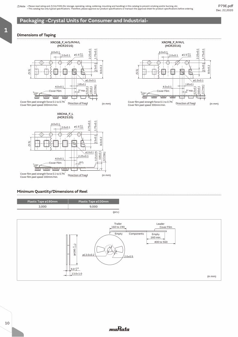
Packaging -Crystal Units for Consumer and Industrial-
Minimum Quantity/Dimensions of Reel
Plastic Tape ø180mm Plastic Tape ø330mm
3,000 9,000
(in mm)
0 –1
.5(ø
18
0
)
Trailer
160 to 190
Empty
160 min.
400 to 560
Cover Film
Leader
Empty Components
ø13.0±0.22.0±0.5
13.0±1.0
+1.0 09.0
(pcs.)
4.0±0.1
2.0±0.1 ø1.5+0.1–0.0
1.7
5±
0.1
3.5
±0
.1
8.0
±0
.2
2.7
5±
0.1
ø1.0±0.1
4.0±0.12.25±0.1
(5°)
(5.5
)
10°
(in mm)Cover film peel strength force 0.1 to 0.7N
Cover film peel speed 300mm/min.
(1.5
max
.)
0.8
5±0
.1
0.2
5±0
.05
Cover Film
Direction of Feed
4.0±0.1
2.0±0.1 ø1.5+0.1–0.0
1.7
5±
0.1
3.5
±0
.1
8.0
±0
.2
2.2
5±
0.1
ø1.0±0.1
4.0±0.11.85±0.1
5° max.
0.2
5±0
.1
(5.5
)
10°
(in mm)Cover film peel strength force 0.1 to 0.7N
Cover film peel speed 300mm/min.
(1.2
max
.)
Cover Film
Direction of Feed
0.6
0±0
.1
4.0±0.1
2.0±0.1 ø1.5+0.1–0.0
1.7
5±
0.1
3.5
±0
.1
8.0
±0
.2
2.2
5±
0.1
ø1.0±0.1
4.0±0.11.85±0.1
5° max.
0.2
5±0
.1
(5.5
)
10°
(in mm)Cover film peel strength force 0.1 to 0.7N
Cover film peel speed 300mm/min.
(1.6
max
.)
Cover Film
Direction of Feed
1.0
0±0
.1
Dimensions of Taping
XRCHA_F_L(HCR2520)
XRCPB_F_P/M/L(HCR2016)
XRCGB_F_H/S/P/M/L(HCR2016)
P79E.pdfDec. 22,2020
!Note • Please read rating and !CAUTION (for storage, operating, rating, soldering, mounting and handling) in this catalog to prevent smoking and/or burning, etc.• This catalog has only typical specifications. Therefore, please approve our product specifications or transact the approval sheet for product specifications before ordering.
10
1
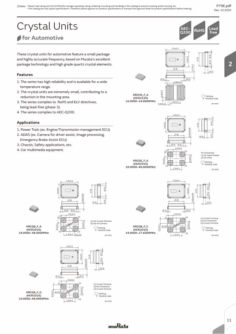
These crystal units for automotive feature a small package and highly accurate frequency, based on Murata's excellent package technology and high grade quartz crystal elements.
Features
1. The series has high reliability and is available for a wide temperature range.2. The crystal units are extremely small, contributing to a
reduction in the mounting area.3. The series complies to RoHS and ELV directives, being lead-free (phase 3).4. The series complies to AEC-Q200.
Applications
1. Power Train (ex. Engine/Transmission management ECU)2. ADAS (ex. Camera for driver assist, Image processing, Emergency Brake Assist ECU)3. Chassis, Safety applications, etc.4. Car multimedia equipment.
Marking
Monthly Code
(in mm)
2.5±0.1
2.0
±0
.1 (0.2
)
(0.2)(0.2)
(1.9
)
(0.3)
0.85±0.1
0.7
±0
.1
1.45±0.10.4±0.1
0.4
±0
.1
(2.4)
(0.2
)
Marking
Monthly Code
(in mm)
2.0±0.1
(1.8)
0.9
±0
.10
.65
±0
.05
(0.2
)(0
.2)
(0.2)
(1)
(4)
(2)
(3)
(0.2)
(1.4
)
1.6
±0
.10
.5±
0.1
0.5±0.1
1.3±0.1
(0.3)
Pin Connection
(1) (3): Input/Output
(2) (4): Float
Marking
Monthly Code
(in mm)
2.0±0.1
(1.8)
0.9
±0
.10
.65
±0
.05
(0.2
)(0
.2)
(0.2)
(1)
(4)
(2)
(3)
(0.2)
(1.4
)
1.6
±0
.10
.5±
0.1
0.5±0.1
1.3±0.1
(0.3)
(0.15)
(1) (3): Crystal Terminal
(2) (4): No Connect
XRCHA_F_A(HCR2520)
16.0000–24.0000MHz
XRCGE_F_A(HCR2016)
20.0000–40.0000MHz
XRCGB_F_A(HCR2016)
24.0000–48.0000MHz
Marking
Monthly Code
(in mm)
2.0±0.1
1.6
±0
.1 (0.1
)
(0.1)(0.1)
(1.4
)
(0.3)
0.5±0.1
0.6
5±
0.0
5
0.9
±0
.1
1.3±0.1
0.5
±0
.1
(1.8)
(0.1
)
(1) Crystal Terminal
(2) No Connection
(3) Crystal Terminal
(0.15)
(1)
(3)
(2)
XRCGB_F_C(HCR2016)
24.0000–27.6000MHz
Crystal Unitsfor Automotive
LeadfreeRoHSAEC-
Q200
Marking
Monthly Code
(in mm)
2.0±0.1
1.6
±0
.1 (0.1
)
(0.1)(0.1)
(1.4
)
(0.3)
0.5±0.1
0.6
5±
0.0
5
0.9
±0
.1
1.3±0.1
0.5
±0
.1
(1.8)
(0.1
)
(1) Crystal Terminal
(2) No Connection
(3) Crystal Terminal
(0.15)
(1)
(3)
(2)
XRCGB_F_G(HCR2016)
24.0000–48.0000MHz
P79E.pdfDec. 22,2020
!Note • Please read rating and !CAUTION (for storage, operating, rating, soldering, mounting and handling) in this catalog to prevent smoking and/or burning, etc.• This catalog has only typical specifications. Therefore, please approve our product specifications or transact the approval sheet for product specifications before ordering.
11
2
Part Number TypeFrequency
(MHz)
Frequency Tolerance(ppm max.)
[at 25°C±3°C]
Frequency Shift by Temperature (ppm max.)[Standard Condition: +25°C]
FrequencyAging
(ppm max./Year)
ESR*
(Ωmax.)
LoadCapacitance
(pF)
DriveLevel
(μW max.)
XRCHA16M000F0A01R0 HCR2520 16.0000 ±100 ±100 (-40 to +125°C) ±5 100 8 300XRCHA16M000F0A11R0 HCR2520 16.0000 ±100 ±100 (-40 to +125°C) ±5 100 8 600XRCHA16M000F0A12R0 HCR2520 16.0000 ±100 ±100 (-40 to +150°C) ±5 100 8 300XRCHA16M000F0A13R0 HCR2520 16.0000 ±100 ±100 (-40 to +150°C) ±5 100 8 600XRCHA20M000F0A01R0 HCR2520 20.0000 ±100 ±100 (-40 to +125°C) ±5 80 8 300XRCHA20M000F0A11R0 HCR2520 20.0000 ±100 ±100 (-40 to +125°C) ±5 80 8 600XRCHA20M000F0A12R0 HCR2520 20.0000 ±100 ±100 (-40 to +150°C) ±5 80 8 300XRCHA20M000F0A13R0 HCR2520 20.0000 ±100 ±100 (-40 to +150°C) ±5 80 8 600XRCHA24M000F0A01R0 HCR2520 24.0000 ±100 ±100 (-40 to +125°C) ±5 80 8 300XRCHA24M000F0A11R0 HCR2520 24.0000 ±100 ±100 (-40 to +125°C) ±5 80 8 600XRCHA24M000F0A12R0 HCR2520 24.0000 ±100 ±100 (-40 to +150°C) ±5 80 8 300XRCHA24M000F0A13R0 HCR2520 24.0000 ±100 ±100 (-40 to +150°C) ±5 80 8 600
* Equivalent Series Resistance
* Equivalent Series Resistance
* Equivalent Series Resistance
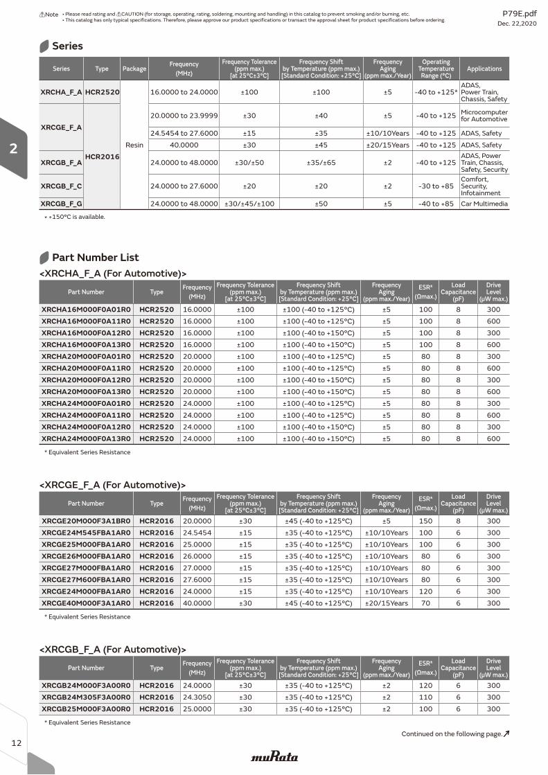
<XRCHA_F_A (For Automotive)>
Part Number List
Part Number TypeFrequency
(MHz)
Frequency Tolerance(ppm max.)
[at 25°C±3°C]
Frequency Shift by Temperature (ppm max.)[Standard Condition: +25°C]
FrequencyAging
(ppm max./Year)
ESR*
(Ωmax.)
LoadCapacitance
(pF)
DriveLevel
(μW max.)
XRCGE20M000F3A1BR0 HCR2016 20.0000 ±30 ±45 (-40 to +125°C) ±5 150 8 300XRCGE24M545FBA1AR0 HCR2016 24.5454 ±15 ±35 (-40 to +125°C) ±10/10Years 100 6 300XRCGE25M000FBA1AR0 HCR2016 25.0000 ±15 ±35 (-40 to +125°C) ±10/10Years 100 6 300XRCGE26M000FBA1AR0 HCR2016 26.0000 ±15 ±35 (-40 to +125°C) ±10/10Years 80 6 300XRCGE27M000FBA1AR0 HCR2016 27.0000 ±15 ±35 (-40 to +125°C) ±10/10Years 80 6 300XRCGE27M600FBA1AR0 HCR2016 27.6000 ±15 ±35 (-40 to +125°C) ±10/10Years 80 6 300XRCGE24M000FBA1AR0 HCR2016 24.0000 ±15 ±35 (-40 to +125°C) ±10/10Years 120 6 300XRCGE40M000F3A1AR0 HCR2016 40.0000 ±30 ±45 (-40 to +125°C) ±20/15Years 70 6 300
Part Number TypeFrequency
(MHz)
Frequency Tolerance(ppm max.)
[at 25°C±3°C]
Frequency Shift by Temperature (ppm max.)[Standard Condition: +25°C]
FrequencyAging
(ppm max./Year)
ESR*
(Ωmax.)
LoadCapacitance
(pF)
DriveLevel
(μW max.)
XRCGB24M000F3A00R0 HCR2016 24.0000 ±30 ±35 (-40 to +125°C) ±2 120 6 300XRCGB24M305F3A00R0 HCR2016 24.3050 ±30 ±35 (-40 to +125°C) ±2 110 6 300XRCGB25M000F3A00R0 HCR2016 25.0000 ±30 ±35 (-40 to +125°C) ±2 100 6 300
<XRCGE_F_A (For Automotive)>
<XRCGB_F_A (For Automotive)>
Series Type PackageFrequency
(MHz)
Frequency Tolerance(ppm max.)
[at 25°C±3°C]
Frequency Shift by Temperature (ppm max.)[Standard Condition: +25°C]
FrequencyAging
(ppm max./Year)
OperatingTemperatureRange (°C)
Applications
XRCHA_F_A HCR2520
Resin
16.0000 to 24.0000 ±100 ±100 ±5 -40 to +125*ADAS, Power Train, Chassis, Safety
XRCGE_F_A
HCR2016
20.0000 to 23.9999 ±30 ±40 ±5 -40 to +125 Microcomputer for Automotive
24.5454 to 27.6000 ±15 ±35 ±10/10Years -40 to +125 ADAS, Safety
40.0000 ±30 ±45 ±20/15Years -40 to +125 ADAS, Safety
XRCGB_F_A 24.0000 to 48.0000 ±30/±50 ±35/±65 ±2 -40 to +125ADAS, Power Train, Chassis, Safety, Security
XRCGB_F_C 24.0000 to 27.6000 ±20 ±20 ±2 -30 to +85Comfort, Security, Infotainment
XRCGB_F_G 24.0000 to 48.0000 ±30/±45/±100 ±50 ±5 -40 to +85 Car Multimedia
* +150°C is available.
Series
Continued on the following page.
P79E.pdfDec. 22,2020
!Note • Please read rating and !CAUTION (for storage, operating, rating, soldering, mounting and handling) in this catalog to prevent smoking and/or burning, etc.• This catalog has only typical specifications. Therefore, please approve our product specifications or transact the approval sheet for product specifications before ordering.
12
2
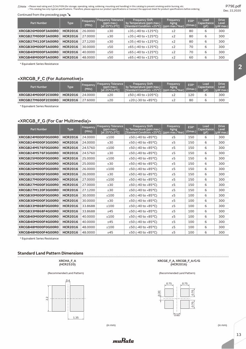
Standard Land Pattern Dimensions
XRCHA_F_A(HCR2520)
XRCGE_F_A, XRCGB_F_A/C/G(HCR2016)
(Recommended Land Pattern)
(in mm)
0.4
1.35
2.2
(Recommended Land Pattern)
(in mm)
0.75
0.60
0.75
0.30 0.70
0.70
* Equivalent Series Resistance
Part Number TypeFrequency
(MHz)
Frequency Tolerance(ppm max.)
[at 25°C±3°C]
Frequency Shift by Temperature (ppm max.)[Standard Condition: +25°C]
FrequencyAging
(ppm max./Year)
ESR*
(Ωmax.)
LoadCapacitance
(pF)
DriveLevel
(μW max.)
XRCGB24M000F0G00R0 HCR2016 24.0000 ±100 ±50 (-40 to +85°C) ±5 150 6 300XRCGB24M000F3G00R0 HCR2016 24.0000 ±30 ±50 (-40 to +85°C) ±5 150 6 300XRCGB24M576F0G00R0 HCR2016 24.5760 ±100 ±50 (-40 to +85°C) ±5 150 6 300XRCGB24M576F3G00R0 HCR2016 24.5760 ±30 ±50 (-40 to +85°C) ±5 150 6 300XRCGB25M000F0G00R0 HCR2016 25.0000 ±100 ±50 (-40 to +85°C) ±5 150 6 300XRCGB25M000F3G00R0 HCR2016 25.0000 ±30 ±50 (-40 to +85°C) ±5 150 6 300XRCGB26M000F0G00R0 HCR2016 26.0000 ±100 ±50 (-40 to +85°C) ±5 150 6 300XRCGB26M000F3G00R0 HCR2016 26.0000 ±30 ±50 (-40 to +85°C) ±5 150 6 300XRCGB27M000F0G00R0 HCR2016 27.0000 ±100 ±50 (-40 to +85°C) ±5 150 6 300XRCGB27M000F3G00R0 HCR2016 27.0000 ±30 ±50 (-40 to +85°C) ±5 150 6 300XRCGB27M120F3G00R0 HCR2016 27.1200 ±30 ±50 (-40 to +85°C) ±5 150 6 300XRCGB30M000F0G00R0 HCR2016 30.0000 ±100 ±50 (-40 to +85°C) ±5 100 6 300XRCGB30M000F3G00R0 HCR2016 30.0000 ±30 ±50 (-40 to +85°C) ±5 100 6 300XRCGB33M868F0G00R0 HCR2016 33.8688 ±100 ±50 (-40 to +85°C) ±5 100 6 300XRCGB33M868F4G00R0 HCR2016 33.8688 ±45 ±50 (-40 to +85°C) ±5 100 6 300XRCGB40M000F0G00R0 HCR2016 40.0000 ±100 ±50 (-40 to +85°C) ±5 100 6 300XRCGB40M000F4G00R0 HCR2016 40.0000 ±45 ±50 (-40 to +85°C) ±5 100 6 300XRCGB48M000F0G00R0 HCR2016 48.0000 ±100 ±50 (-40 to +85°C) ±5 100 6 300XRCGB48M000F4G00R0 HCR2016 48.0000 ±45 ±50 (-40 to +85°C) ±5 100 6 300
<XRCGB_F_G (For Car Multimedia)>
* Equivalent Series Resistance
* Equivalent Series Resistance
Part Number TypeFrequency
(MHz)
Frequency Tolerance(ppm max.)
[at 25°C±3°C]
Frequency Shift by Temperature (ppm max.)[Standard Condition: +25°C]
FrequencyAging
(ppm max./Year)
ESR*
(Ωmax.)
LoadCapacitance
(pF)
DriveLevel
(μW max.)
XRCGB24M000F2C00R0 HCR2016 24.0000 ±20 ±50 (-40 to +105°C) ±2 120 6 300XRCGB27M600F2C00R0 HCR2016 27.6000 ±20 ±20 (-30 to +85°C) ±2 80 6 300
<XRCGB_F_C (For Automotive)>
Part Number TypeFrequency
(MHz)
Frequency Tolerance(ppm max.)
[at 25°C±3°C]
Frequency Shift by Temperature (ppm max.)[Standard Condition: +25°C]
FrequencyAging
(ppm max./Year)
ESR*
(Ωmax.)
LoadCapacitance
(pF)
DriveLevel
(μW max.)
XRCGB26M000F3A00R0 HCR2016 26.0000 ±30 ±35 (-40 to +125°C) ±2 80 6 300XRCGB27M000F3A00R0 HCR2016 27.0000 ±30 ±35 (-40 to +125°C) ±2 80 6 300XRCGB27M120F3A00R0 HCR2016 27.1200 ±30 ±35 (-40 to +125°C) ±2 80 6 300XRCGB30M000F5A00R0 HCR2016 30.0000 ±50 ±65 (-40 to +125°C) ±2 70 6 300XRCGB40M000F5A00R0 HCR2016 40.0000 ±50 ±65 (-40 to +125°C) ±2 70 6 300XRCGB48M000F5A00R0 HCR2016 48.0000 ±50 ±65 (-40 to +125°C) ±2 60 6 300
Continued from the preceding page.
P79E.pdfDec. 22,2020
!Note • Please read rating and !CAUTION (for storage, operating, rating, soldering, mounting and handling) in this catalog to prevent smoking and/or burning, etc.• This catalog has only typical specifications. Therefore, please approve our product specifications or transact the approval sheet for product specifications before ordering.
13
2
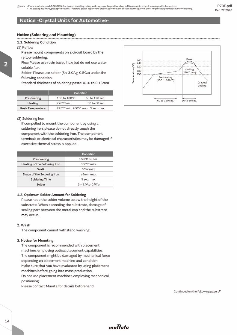
Notice -Crystal Units for Automotive-
Please mount components on a circuit board by the reflow soldering.Flux: Please use rosin based flux; but do not use water soluble flux. Solder: Please use solder (Sn-3.0Ag-0.5Cu) under the following condition.Standard thickness of soldering paste: 0.10 to 0.15mm
1.1. Soldering Condition
Please keep the solder volume below the height of the substrate. When exceeding the substrate, damage of sealing part between the metal cap and the substrate may occur.
1.2. Optimum Solder Amount for Soldering
The component cannot withstand washing.2. Wash
The component is recommended with placement machines employing optical placement capabilities.The component might be damaged by mechanical force depending on placement machine and condition.Make sure that you have evaluated by using placement machines before going into mass production.Do not use placement machines employing mechanical positioning.Please contact Murata for details beforehand.
3. Notice for Mounting
(1) Reflow
Pre-heating
Condition
150 to 180°C
Heating 220°C min.
Peak Temperature 245°C min. 260°C max.
60 to 120 sec.
30 to 60 sec.
5 sec. max.
(2) Soldering Iron
Pre-heating
Condition
150°C 60 sec.
Heating of the Soldering Iron 350°C max.
Watt
Shape of the Soldering Iron
Soldering Time
Solder
30W max.
ø3mm max.
5 sec. max.
Sn-3.0Ag-0.5Cu
150180
220245260
GradualCooling
Peak
Pre-heating(150 to 180°C)
Heating(220°C min.)
60 to 120 sec. 30 to 60 sec.
Tem
pera
ture
(°C
)
Notice (Soldering and Mounting)
If compelled to mount the component by using a soldering iron, please do not directly touch the component with the soldering iron. The component terminals or electrical characteristics may be damaged if excessive thermal stress is applied.
Continued on the following page.
P79E.pdfDec. 22,2020
!Note • Please read rating and !CAUTION (for storage, operating, rating, soldering, mounting and handling) in this catalog to prevent smoking and/or burning, etc.• This catalog has only typical specifications. Therefore, please approve our product specifications or transact the approval sheet for product specifications before ordering.
14
2
Notice -Crystal Units for Automotive-
Notice (Storage and Operating Condition)
1. Product Storage Condition
Please store the products in room where the
temperature/humidity is stable. And avoid
such places where there are large temperature
changes. Please store the products under the
following conditions:
Temperature: -10 to + 40 degrees C
Humidity: 15 to 85% R.H.
2. Expire Date on Storage
Expiration date (shelf life) of the products is 6 months
after delivery under the conditions of an unopened
package. Please use the products within 6 months after
delivery. If you store the products for a long time (more
than 6 months), use carefully because the products may
be degraded in solderability and/or rusty.
Please confirm solderability and characteristics for the
products regularly.
3. Notice on Product Storage
(1) Please do not store the products in a chemical
atmosphere (Acids, Alkali, Bases, Organic gas,
Sulfides and so on), because the characteristics
may be reduced in quality, and/or be degraded in
solderability due to the storage in a
chemical atmosphere.
(2) Please do not put the products directly on the
floor without anything under them to avoid damp
places and/or dusty places.
(3) Please do not store the products in the places under
direct sunlight, heat and vibration.
(4) Please use the products immediately after the
package is opened, because the characteristics
may be reduced in quality, and/or be degraded in
solderability due to storage under poor
conditions.
(5) Please do not drop the products to avoid cracking
the crystal element.
4. Other
Conformal coating or washing of the component is not
acceptable because it is not hermetically sealed.
Please be sure to consult with our sales representative
or engineer whenever and prior to using the products.
Notice (Rating)
The component may be damaged if excess mechanical
stress is applied.
Notice (Handling)
1. Irregular or stopped oscillation may occur under
unmatched circuit conditions.
Please design your oscillation circuit to get 5
times or more of a negative resistance against
the maximum value of the Equivalent Series
Resistance, that is specified in order.
2. Be sure to provide an appropriate fail-safe
function on your product to prevent a second
damage that may be caused by the abnormal
function or the failure of our product.
Continued from the preceding page.
P79E.pdfDec. 22,2020
!Note • Please read rating and !CAUTION (for storage, operating, rating, soldering, mounting and handling) in this catalog to prevent smoking and/or burning, etc.• This catalog has only typical specifications. Therefore, please approve our product specifications or transact the approval sheet for product specifications before ordering.
15
2
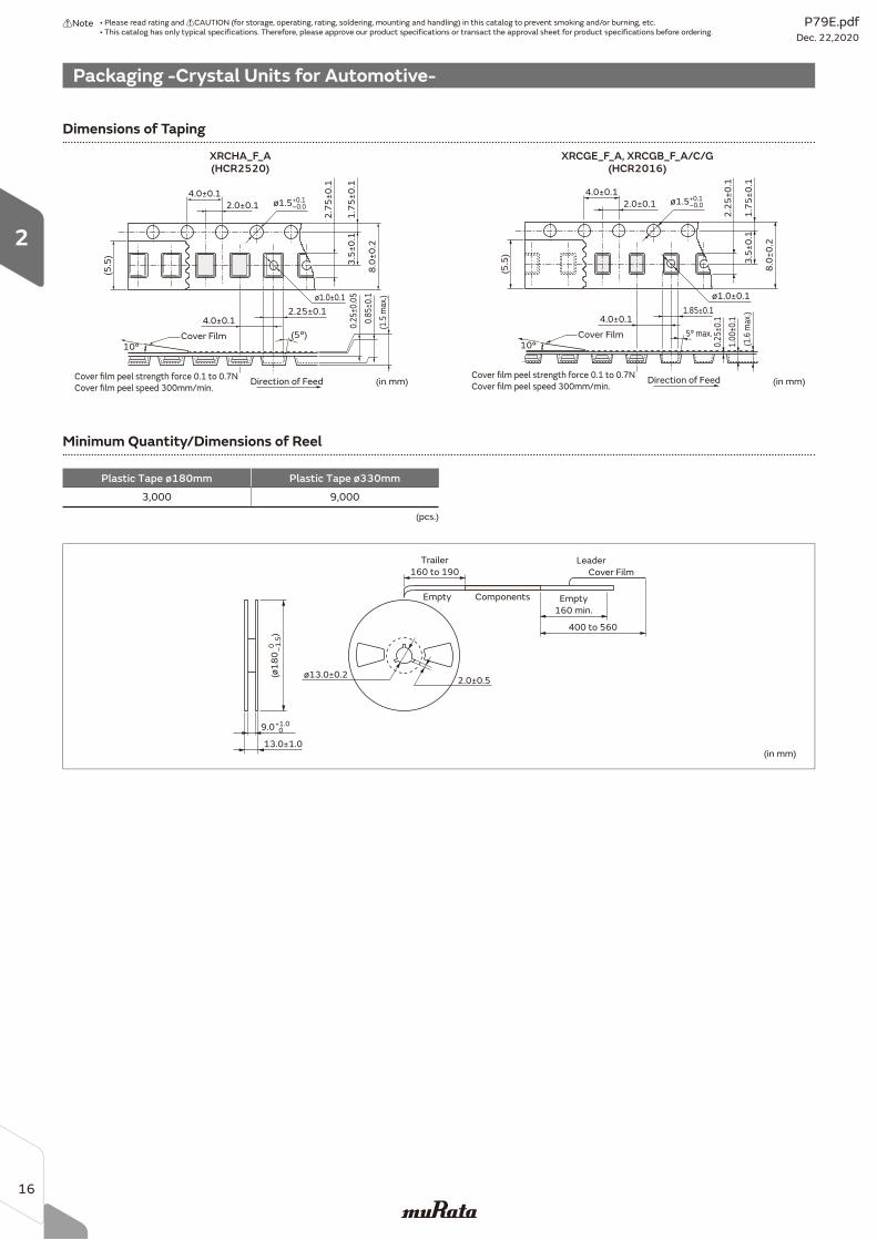
Packaging -Crystal Units for Automotive-
Minimum Quantity/Dimensions of Reel
Plastic Tape ø180mm Plastic Tape ø330mm
3,000 9,000
(in mm)
0 –1
.5(ø
18
0
)
Trailer
160 to 190
Empty
160 min.
400 to 560
Cover Film
Leader
Empty Components
ø13.0±0.22.0±0.5
13.0±1.0
+1.0 09.0
(pcs.)
4.0±0.1
2.0±0.1 ø1.5+0.1–0.0
1.7
5±
0.1
3.5
±0
.1
8.0
±0
.2
2.7
5±
0.1
ø1.0±0.1
4.0±0.12.25±0.1
(5°)
(5.5
)
10°
(in mm)Cover film peel strength force 0.1 to 0.7N
Cover film peel speed 300mm/min.(1
.5 m
ax.)
0.8
5±0
.1
0.2
5±0
.05
Cover Film
Direction of Feed
4.0±0.1
2.0±0.1 ø1.5+0.1–0.0
1.7
5±
0.1
3.5
±0
.1
8.0
±0
.2
2.2
5±
0.1
ø1.0±0.1
4.0±0.11.85±0.1
5° max.
0.2
5±0
.1
(5.5
)
10°
(in mm)Cover film peel strength force 0.1 to 0.7N
Cover film peel speed 300mm/min.
(1.6
max
.)
Cover Film
Direction of Feed
1.0
0±0
.1
Dimensions of Taping
XRCHA_F_A(HCR2520)
XRCGE_F_A, XRCGB_F_A/C/G(HCR2016)
P79E.pdfDec. 22,2020
!Note • Please read rating and !CAUTION (for storage, operating, rating, soldering, mounting and handling) in this catalog to prevent smoking and/or burning, etc.• This catalog has only typical specifications. Therefore, please approve our product specifications or transact the approval sheet for product specifications before ordering.
16
2

Measuring Circuit of Crystal Units
The load resonance frequency (Lower frequency of the
two given when the electrical impedance of the
component becomes resistant near its resonance point)
is measured by network analyzer (KEYSIGHT E5100A or
the equivalent) and the circuit in Figure 1. DUT is shown
in Figure 2, and the value of Cs refers to the load
capacitance value in specifications.
1. Frequency Measuring Method
The equivalent series resistance (ESR) is measured by
network analyzer (KEYSIGHT E5100A or equivalent) and
the circuit in Figure 1. DUT is shown in Figure 3.
2. Equivalent Series Resistance
Standard conditions for measurement shall be +25±3°C
temperature and humidity of 45 to 85%R.H.
3. Measuring Condition
Measuring Circuit 1
Cs
L1 ESRC1
Co
Network Analyzer
DUT
OUT1 OUT2
66.2Ω 66.2Ω
159Ω 159Ω14.2Ω 14.2Ω
R A
Figure 1 Frequency Measuring Circuit
Figure 2 DUT (Device Under Test)
Figure 3 DUT (Device Under Test)
The load resonance frequency is measured by network
analyzer (S&A 250B or the equivalent) and the circuit in
Figure 1. Measured frequency may be changed by using
different measurement equipment.
1. Frequency Measuring Method
The equivalent series resistance (ESR) is measured by
network analyzer (S&A 250B or equivalent) and the
circuit in Figure 1. DUT is shown in Figure 2.
2. Equivalent Series Resistance
Standard conditions for measurement shall be +30±0.5°C
and 25 to 75%R.H.
3. Measuring Condition
Measuring Circuit 2
L1 ESRC1
Co
Network Analyzer
DUT
OUT1
66.2Ω 66.2Ω
159Ω 159Ω14.2Ω 14.2Ω
A
Figure 1 Frequency Measuring Circuit
Figure 2 DUT (Device Under Test)
P79E.pdfDec. 22,2020
!Note • Please read rating and !CAUTION (for storage, operating, rating, soldering, mounting and handling) in this catalog to prevent smoking and/or burning, etc.• This catalog has only typical specifications. Therefore, please approve our product specifications or transact the approval sheet for product specifications before ordering.
17
Murata Manufacturing Co., Ltd.
www.murata.com
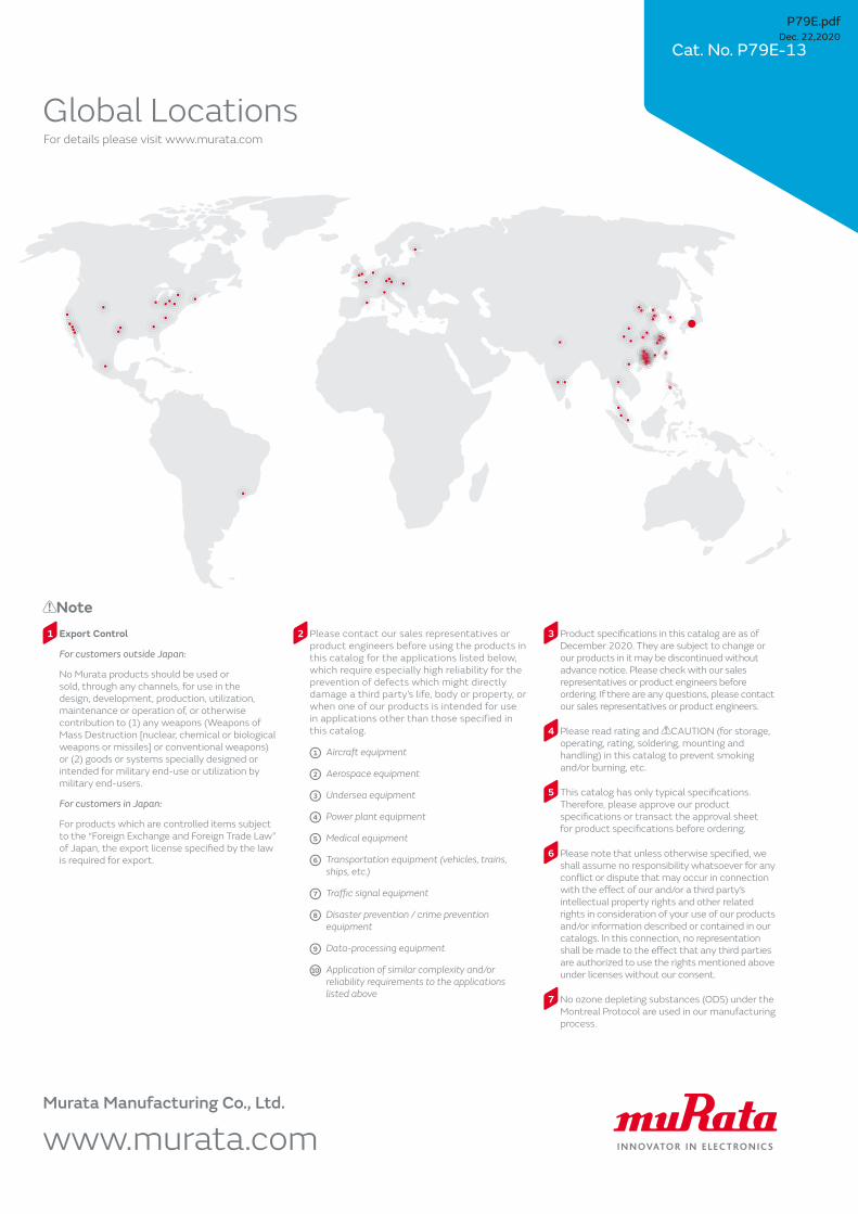
Note1 Export Control
For customers outside Japan:
No Murata products should be used or
sold, through any channels, for use in the
design, development, production, utilization,
maintenance or operation of, or otherwise
contribution to (1) any weapons (Weapons of
Mass Destruction [nuclear, chemical or biological
weapons or missiles] or conventional weapons)
or (2) goods or systems specially designed or
intended for military end-use or utilization by
military end-users.
For customers in Japan:
For products which are controlled items subject
to the “Foreign Exchange and Foreign Trade Law”
of Japan, the export license specifi ed by the law
is required for export.
2 Please contact our sales representatives or
product engineers before using the products in
this catalog for the applications listed below,
which require especially high reliability for the
prevention of defects which might directly
damage a third party’s life, body or property, or
when one of our products is intended for use
in applications other than those specified in
this catalog.
1 Aircraft equipment
2 Aerospace equipment
3 Undersea equipment
4 Power plant equipment
5 Medical equipment
6 Transportation equipment (vehicles, trains,
ships, etc.)
7 Traffi c signal equipment
8 Disaster prevention / crime prevention
equipment
9 Data-processing equipment
10 Application of similar complexity and/or
reliability requirements to the applications
listed above
3 Product specifi cations in this catalog are as of
December 2020. They are subject to change or
our products in it may be discontinued without
advance notice. Please check with our sales
representatives or product engineers before
ordering. If there are any questions, please contact
our sales representatives or product engineers.
4 Please read rating and CAUTION (for storage,
operating, rating, soldering, mounting and
handling) in this catalog to prevent smoking
and/or burning, etc.
5 This catalog has only typical specifi cations.
Therefore, please approve our product
specifi cations or transact the approval sheet
for product specifi cations before ordering.
6 Please note that unless otherwise specifi ed, we
shall assume no responsibility whatsoever for any
confl ict or dispute that may occur in connection
with the eff ect of our and/or a third party’s
intellectual property rights and other related
rights in consideration of your use of our products
and/or information described or contained in our
catalogs. In this connection, no representation
shall be made to the eff ect that any third parties
are authorized to use the rights mentioned above
under licenses without our consent.
7 No ozone depleting substances (ODS) under the
Montreal Protocol are used in our manufacturing
process.
Global LocationsFor details please visit www.murata.com
Cat. No. P79E-13
P79E.pdfDec. 22,2020