cryogenic wavefront error measurement for the james … · cryogenic wavefront error measurement...
TRANSCRIPT

Cryogenic wavefront error measurement for the James Webb Space Telescope fine guidance sensor powered optics
Clinton E. Evansa, Elliot S. Greenberga, David A. Aldridgea, Jeffrey J. Santmanb
aCOM DEV Canada Ltd., 303 Terry Fox Drive, Suite 100, Ottawa, ON, Canada K2K 0P9; bCorning NetOptix, 69 Island Street, Keene, NH, USA 03431
ABSTRACT
The Fine Guidance Sensor (FGS) is part of the instrument module for the James Webb Space Telescope (JWST). The FGS operates at 37 K and provides feedback to correct motion blur caused by relative motion within the observatory - an issue during long exposures. It also provides a tunable camera for science observations.
The FGS powered optics comprises three, Three Mirror Assembly (TMA) - style reflective systems - one with finite conjugates and the remaining two are an infinite/finite conjugate pair. This paper addresses the issues of providing traceable interferometric wave-front error measurements when the test optics are in a cryogenic vacuum chamber. To meet space and time limits, we restrict attention to the finite conjugate device for the purposes of this publication.
Keywords: Optical-Path-Difference (OPD), OPD-Measurement, Vacuum, Cryogenic, Interferometry, James Webb Space Telescope (JWST), Fine Guidance Sensor (FGS)
1. INTRODUCTION
Interferometric lens-testing in a room-temperature environment is a well-established but difficult technology. Adapting it for measuring the OPD of an optical system at 37 K in a Cryogenic Vacuum Chamber (CVC) must address some additional issues. With the complete interferometric cavity in the CVC, they include:
• maintaining correct operation of transmission spheres, reference spheres, mounting systems and other items that define the interferometer cavity,
• tracing the operation and geometry of the cavity in the cryogenic environment to a recognized standard, and
• making phase-shifting adjustments to an inaccessible cavity.
Alternatively, if part of the cavity is outside of the chamber, the phase-shifting may be carried out in the normal manner using the interferometer's translation system. However, there is a need to compensate for the aberrations generated by thermally and mechanically stressed windows.
We elected to operate the complete cavity within the chamber and this paper describes our approach to addressing the issues raised above.
1.1 Interferometric Cavity Geometry
Figure 1 shows the interferometer test geometry with just three of the ten test-fields shown, for clarity. The FGS powered optical system comprises a rotationally-symmetric Three-Mirror Assembly (TMA) where the apertures only are asymmetric to provide for the passage of light. The complete instrument uses aluminum alloy 6061 for optical surfaces and structure – part of our design strategy for manufacture at room temperature and operation at 37 K.
The cavity structure continues this theme with a 6061 base plate and a reference sphere array, known internally as the Output Beam Alignment Tool (OBAT). There are ten reference spheres with their centers of curvature at the field locations chosen for the test. The centers of curvature lie on a curved surface to compensate for field curvature required in the FGS design.
Interferometry XV: Techniques and Analysis, edited by Catherine E. Towers, Joanna Schmit, Katherine Creath, Proc. of SPIE Vol. 7790, 779004 · © 2010 SPIE · CCC code: 0277-786X/10/$18 · doi: 10.1117/12.860856
Proc. of SPIE Vol. 7790 779004-1
Downloaded From: http://spiedigitallibrary.org/ on 05/28/2013 Terms of Use: http://spiedl.org/terms

Figure 1. Interferometric test geometry
This arrangement operates satisfactorily at room temperature, 37 K, and a variety of temperatures in between, however, we use different transmission sphere approaches for room-temperature and cryogenic measurements. At room temperature, we use a commercial Zygo transmission sphere and phase-shifting interferometer. For cryogenic testing, we use:
• A wavelength-shifting interferometer
o It operates outside the CVC in the lab environment and views the interferometer cavity through the CVC window.
• A novel design of transmission sphere
o It operates within the CVC but maintains its temperature at 293 K.
An additional item in the test configuration plays no direct part in the OPD measurement. Known internally as the Input Beam Alignment Tool (IBAT), it comprises an array of small spherical mirrors located at the intermediate image shared with the transmission sphere. Each mirror has a small hole for the passage of light. The center of curvature of each surface is on a specified test field and in the image plane. This fixture provides a precision datum for measuring the location and defocus of the test fields.
1.2 FGS Design Aberrations
Figure 2 shows a plot of the nominal FGS optical correction expressed as OPD in nm. The calculation uses a curved object surface to remove the design field curvature and the fields correspond to the three selected in Figure 1. The aberrations are quite small for a near-infrared instrument but the original design targets were non-zero and partially compensate for aberrations received from the JWST objective. The OPD measurements require some compensation to reflect a departure from non-zero targets. Fortunately, with the field curvature removed by the fixture, the aberrations are well within the non-aliasing range of the interferometer.
Proc. of SPIE Vol. 7790 779004-2
Downloaded From: http://spiedigitallibrary.org/ on 05/28/2013 Terms of Use: http://spiedl.org/terms

Y-EAN
100 mu
-100 flifi
-100 niri
100 fllii
-110 n
1.12 1.93
-0.54 , 3.59
0.29 , 2.76
X- FAN
100 n
JL00 flIIk
100 nm
-100 rim
If we tested an accurately nominal optical system with an accurately nominal test setup, we would measure the design aberrations of the instrument. For the purpose of manufacturing and internal performance budgets, we use the design aberrations as targets and subtract them during post-processing. Thus, a perfectly made and tested system would produce zero OPD error. This arrangement provides a direct assessment of the build precision and provides for adjustment during assembly.
Figure 2. FGS nominal correction
2. MECHANICAL TEST IMPLEMENTATION FOR WARM TEST
2.1 Mechanical characteristics of FGS
The FGS instrument optics and optical bench are an all aluminum athermal design that allows the instrument to maintain optical alignment during cool down to the operational temperature of 30 Kelvin. All metallic materials will undergo rigorous thermal stress relief processes, to cryogenic temperatures, in order to minimize risk of relaxation during test and
Proc. of SPIE Vol. 7790 779004-3
Downloaded From: http://spiedigitallibrary.org/ on 05/28/2013 Terms of Use: http://spiedl.org/terms

Guider Side of FGS TFI Side of FGS
operation. The FGS instrument is mounted in the Integrated Science Instrument Module (ISIM) structure with three bipod kinematic mounts, which nominally constrain the instrument in six degrees of freedom. The mounting must be kinematic to account for the large thermal expansion mismatch between the ISIM composite structure and the aluminum FGS all while minimizing any loads between the two structures.
Figure 3: FGS Instrument – Baffles Removed
The instrument optical design philosophy uses TMAs for the powered optics. This arrangement provides the required optical correction and compartmentalizes the tightest mechanical tolerances within each TMA. This philosophy works well as there are existing technologies for the manufacturing of high-precision TMAs and allows for looser locational tolerances with respect to the placement of the other components, such as the mechanisms and detectors on the optical bench thus simplifying the assembly and alignment of the optical assemblies. 2.2 Mechanical characteristics of Guider TMA
The Guider TMA consists of three mirrors, a main housing, top and bottom covers, an access panel along with internal stray light baffles All components of the TMA (excluding fasteners) are aluminum 6061-T6, which have been stress relieved and heat treated by the same method to ensure material properties (mainly thermal expansion) are consistent. The TMA mounts to the optical bench via three interface pads, which are integral with the TMA housing. Flexure regions are machined between the pads and the main housing. These flexures are designed to isolate the main housing from distortions caused by machining tolerance, bolt torque or thermal distortion. Each pad is attached to the optical bench with two bolts and the entire TMA is located using a tight tolerance pin and slot configuration. The heat treatment and stress relief of the individual parts and assembled structure are important parts of the FGS instrument and TMA designs. Due to the large temperature difference (~240ºC) between the room temperature manufacture/assemble/alignment and the operational temperature of 30K the optical performance is dependent on “stress-free” temperature transition. Each part of the TMA (mirrors, housing, covers and baffles) goes through the same general process:
1. Rough machine
2. High temperature heat treatment (450 °F 8 hours)
3. Cryogenic Solution Tempering (Cycles of immersion in Liquid Nitrogen to boiling water)
Proc. of SPIE Vol. 7790 779004-4
Downloaded From: http://spiedigitallibrary.org/ on 05/28/2013 Terms of Use: http://spiedl.org/terms
4. Non-Optical Surface Treatment (Iridite, anodize)
5. Rough contour of optical surfaces
6. Deep Cryogenic Thermal Cycle (Cycles between room temperature and 30K)
7. Finish Machine - Final contour and interface fly-cut
8. Optical Surface Coating
The TMA has Iridite surface treatment on external surfaces while, internal non-optical surfaces has a black anodize surface treatment. The black anodize increases the radiative coupling within the TMA structure to aid in minimizing thermal gradients and also aids in stray light control. Stray light is controlled with a combination of physical baffles and surface treatments. Mirror surfaces will have a gold coating with a silicon dioxide protective overcoat which produces the necessary reflectivity over the desired wavelength band (0.8 to 5 microns). 2.3 Assembly and Alignment
The TMA is designed as a bolt together unit to produce good optical performance on assembly. The housing is assembled separately and then thermal cycled to relieve any residual stresses. After thermal cycling the critical surfaces are diamond fly-cut and pin holes jig-bored to create the accurate mirror mounting points needed to produce acceptable optical performance. The mirrors are installed in nominal positions using locating pins (2 per mirror) in the housing with tight fit holes in the mirror mounting pads. Minor adjustments to improve OPD performance is achieved with slight movements of the mirrors (primarily the tertiary mirror) on the pins or by removing the pins if larger adjustments are necessary. These adjustments are done with real time OPD monitoring. 2.4 Common Mounting system for OPD Test
Much of the test hardware is common to both room temperature and cryogenic measurement. Figure 4 shows the arrangement. There is a sturdy, stress-relieved base plate which locates the FGS-Guider, the OBAT and the IBAT.The complete assembly uses the same material and expands and contracts isotropically. Therefore, it is equally suitable for either room-temperature or cryogenic operation.
Figure 4. Common Hardware for OPD Test
Proc. of SPIE Vol. 7790 779004-5
Downloaded From: http://spiedigitallibrary.org/ on 05/28/2013 Terms of Use: http://spiedl.org/terms

FGS-G Lilder
OBAT
IBAT
Testing Base Plate
Zygo I nterterometerAnd Transm isslo n S phere
2.5 Room Temperature OPD Measurement
Figure 5 shows the room temperature OPD measurement scheme. It comprises:
• A Zygo phase-shifting interferometer • A Zygo transmission Sphere • The Common OPD Test Hardware
The complete arrangement locates on an optical table for stability. The interferometer is on a three-axis translation stage so that the transmission sphere focus may be moved from one FGS-Guider focus location to another, viewed through the holes in the IBAT. From there, the test becomes a matter of following the procedure in the Zygo instruction manual for measurement and fringe reduction.
The spheres in the IBAT provide a precision reference for the location of each field point. Adjusting the interferometer for fringes with an IBAT sphere and then for fringes with its corresponding FGS Guider field provides a good measurement of the focus and position error for each field. While not part of the OPD measurement, we need the data for alignment of the complete FGS instrument.
Figure 5. Setup for Room Temperature OPD Measurement
2.6 Cryogenic OPD Measurement
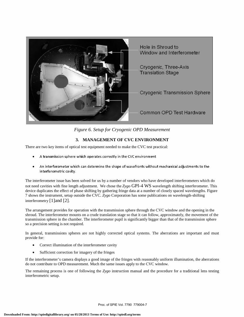
Figure 6 shows the test arrangement for cryogenic OPD measurement. It is a view looking down vertically into the CVC with the lid removed. The Common OPD Test Hardware locates on the base of the CVC, as shown.
There are two additional items:
• An electrically powered cryogenic translation stage
o Controlled from outside the chamber
• A transmission sphere
o The design operates satisfactorily both at room temperature in the cryogenic vacuum environment.
The complete assembly is instrumented in many places to monitor temperature and thermal gradients. The interferometer operates outside the CVC, through the CVC window. Section 3 describes our choice of interferometer and transmission sphere for the cryogenic test.
Proc. of SPIE Vol. 7790 779004-6
Downloaded From: http://spiedigitallibrary.org/ on 05/28/2013 Terms of Use: http://spiedl.org/terms
Hole in Shroud toVVindow and I nterteromete
Cryogenic, Three-AxisTranslation Stage
Cryogenic Transrnisson Sphere
Common OPD Test Hardware
Figure 6. Setup for Cryogenic OPD Measurement
3. MANAGEMENT OF CVC ENVIRONMENT
There are two key items of optical test equipment needed to make the CVC test practical:
• A transmission sphere which operates correctly in the CVC environment
• An interferometer which can determine the shape of wavefronts without mechanical adjustments to the
interferometric cavity.
The interferometer issue has been solved for us by a number of vendors who have developed interferometers which do not need cavities with fine length adjustment. We chose the Zygo GPI-4 WS wavelength shifting interferometer. This device duplicates the effect of phase shifting by gathering fringe data at a number of closely spaced wavelengths. Figure 7 shows the instrument, setup outside the CVC. Zygo Corporation has some publications on wavelength-shifting interferometry [1]and [2]. The arrangement provides for operation with the transmission sphere through the CVC window and the opening in the shroud. The interferometer mounts on a crude translation stage so that it can follow, approximately, the movement of the transmission sphere in the chamber. The interferometer pupil is significantly bigger than that of the transmission sphere so a precision setting is not required. In general, transmissions spheres are not highly corrected optical systems. The aberrations are important and must provide for:
• Correct illumination of the interferometer cavity
• Sufficient correction for imagery of the fringes
If the interferometer’s camera displays a good image of the fringes with reasonably uniform illumination, the aberrations do not contribute to OPD measurement. Much the same issues apply to the CVC window.
The remaining process is one of following the Zygo instruction manual and the procedure for a traditional lens testing interferometric setup.
Proc. of SPIE Vol. 7790 779004-7
Downloaded From: http://spiedigitallibrary.org/ on 05/28/2013 Terms of Use: http://spiedl.org/terms

DIK GA4W$at o stvlls s.ivi
$ O?OS.41$l7T$ iW21
LM.P1L ft ROAD
CLUILD. C? ou
WC tsI Ptr -
WATT$ 3.0
Awl,
Figure 7. Zygo Wavelength Shifting Interferometer
3.1 Transmission Sphere
The CVC-compatible transmission sphere, however, was a problem we had to solve by ourselves. The strategy we adopted was:
• Design a transmission sphere that works at room temperature.
• Build it and qualify it at room temperature.
• Operate it at room temperature in the CVC environment.
• Instrument it to prove it is at room temperature during the OPD test and has acceptable thermal gradients.
Proving the concept works is straight forward. Designing something that will work is more complex. In the CVC environment, a transmission sphere can exchange heat with the surroundings by conduction through the mounting structure and by radiation. There is no convection in a vacuum. We can manage conduction by structural design and some low-power trim heaters. Radiation, however, is more of a problem. Optical glasses are opaque over a significant part of the room-temperature black-body spectral range and radiate strongly to any nearby 37 K structure. We solved this problem by designing and building a Zinc Selenide transmission sphere. This material has very low absorption both at the interferometer wavelength and the room temperature black body spectral range. Figure 8 shows the device.
Proc. of SPIE Vol. 7790 779004-8
Downloaded From: http://spiedigitallibrary.org/ on 05/28/2013 Terms of Use: http://spiedl.org/terms

Figure 8. Zinc Selenide Transmission Sphere.
3.2 Mechanical modeling and control of transmission sphere thermal behaviour.
The key aspect to this OPD test setup is the transmission sphere (reference) being enclosed in the thermal vacuum chamber. This setup has the entire interferometric cavity inside the chamber which removes the large errors due to chamber window distortions. This also introduces new issues of ensuring that the reference maintains its figure during OPD testing. This is not a trivial problem due to the fact that the chamber and article under test are at 30 K.
Figure 9. Transmission Heater Application
Proc. of SPIE Vol. 7790 779004-9
Downloaded From: http://spiedigitallibrary.org/ on 05/28/2013 Terms of Use: http://spiedl.org/terms
A
A
8 7
'AMES:
ASSELLOLE PER RIAA/CSE/17683V001
2. 100011 ALL ORkcIA0E PER eND 5.00S.32
3.81801 11008010 PET COP 7 .008.
IASOEUIC MO IT8M!NAT ON CONTROL: REIOC ALL PM TICULIT C RIOFILER CCRTIMR0LAO OIl !I'RTCAIE 0 1-I 800178! CAL 08000 (OT.99 PlOt)
OROOPO OSEOSIVIL NT).REPEIrVI SUN. S00ECT ON AS 8001)1810 TO ARRIVe PULL CIERIL. TOSS.HANDLE PlOTS AT ALL TI LOS * ITPI LAIT FREE CLOSES.
S. PART hIRER: 800 PIt TAG/RESEll 'IOA!TlERS *1 SR P881 TO.17683T101 885.PO.
76636-101
COIl 00) VS
fALL ES 00 STEER lUll AM
RESET/RI -OR
LENS HOUSING ASSEMBLY
FRONT VIEWSCALE 1.5:1
8.39
r 36.00
Lii
- 3.0O
SIDE VIEWSCALE TOIl
R)0FI,IRI Y
I-SEAS 10 NM SERIES
AR.
COMDEVTRANSMISSION SPHERE,FGS. JT. TMA GSE
1l:iI176636 IP'C.
2
2S 5
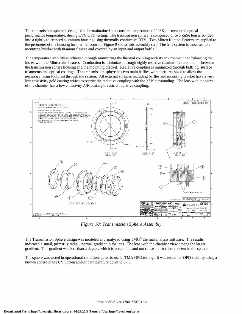
The transmission sphere is designed to be maintained at a constant temperature of 293K, its measured optical performance temperature, during CVC OPD testing. The transmission sphere is comprised of two ZnSe lenses bonded into a tightly toleranced aluminum housing using thermally conductive RTV. Two Minco Kapton Heaters are applied to the perimeter of the housing for thermal control. Figure 9 shows this assembly step. The lens system is mounted to a mounting bracket with titanium flexure and covered by an input and output baffle. The temperature stability is achieved through minimizing the thermal coupling with its environment and balancing the losses with the Minco trim heaters. Conduction is minimized through highly resistive titanium flexure mounts between the transmission sphere housing and the mounting bracket. Radiative coupling is minimized through baffling, surface treatments and optical coatings. The transmission sphere has two main baffles with apertures sized to allow the necessary beam footprint through the system. All external surfaces including baffles and mounting bracket have a very low emissivity gold coating which to restrict the radiative coupling with the 37 K surrounding. The lens with the view of the chamber has a low emissivity A/R coating to restrict radiative coupling.
Figure 10: Transmission Sphere Assembly
The Transmission Sphere design was modeled and analyzed using TMG® thermal analysis software. The results indicated a small, primarily radial, thermal gradient in the lens. The lens with the chamber view having the larger gradient. This gradient was less than a degree, which is acceptable and not cause a distortion concern in the sphere. The sphere was tested in operational conditions prior to use in TMA OPD testing. It was tested for OPD stability using a known sphere in the CVC from ambient temperature down to 37K.
Proc. of SPIE Vol. 7790 779004-10
Downloaded From: http://spiedigitallibrary.org/ on 05/28/2013 Terms of Use: http://spiedl.org/terms

Ambient Measurement (293K) 30K Measurement
Thermal Finite Element Model
Sphere Assembly with Baffles Sphere Assembly Baffles Removed
LensThermal Analysis Results
Figure 11. Transmission Sphere Thermal Model
4. TEST RESULTS
We collected a great deal of cryogenic wavefront data from the FGS Guider but limitations of space prevent our showing most of it. Therefore, we selected a single field from a single instrument that reflects typical behaviour. Figure 12 shows two plots from the Zygo Metropro® software, taken at room temperature and 30 K. Some early measurements showed large changes in OPD between room temperature and the operating environment. These changes were traced to specific design and manufacture issues with the FGS Guider. When corrected, figure 12 is more typical of the changes on cooling.
Figure 12:FGS Guider OPD measurements – Ambient and Cryogenic
Proc. of SPIE Vol. 7790 779004-11
Downloaded From: http://spiedigitallibrary.org/ on 05/28/2013 Terms of Use: http://spiedl.org/terms

IIrHIL1Ik1U' U.
Interferometer
CVC Wall
CVC Window
TX Sphere
Test Sphere
5. TRACEABILITY
The flow of traceability is as follows:
1. Show by thermal modeling that the transmission sphere will function correctly and remain at room temperature in the CVC at 37 K.
2. Verify experimentally the correct operation of the transmission sphere at room temperature against a calibrated test sphere.
3. Instrument the transmission sphere to verify that temperature and thermal gradients during the test are consistent with the thermal model.
4. During any cryogenic test, verify that the temperature and the thermal gradients of the transmission sphere are within the limits found during the room temperature verification test.
In principle, this process should be sufficient. We demonstrate correct operation against a traceable standard at room temperature and then maintain room temperature operation during cryogenic testing. However, we can test the operation of the transmission sphere in the CVC environment more directly.
Figure 13 shows an arrangement for testing the transmission sphere against a stress-relieved metal sphere. We chose a sphere with good OPD at room temperature. And then, repeated the test in the CVC, as shown.
The test should also provide a good wavefront with the chamber cold and under vacuum. Neither the transmission sphere nor the test sphere is strictly traceable cold. However, for this test to succeed but with a deformed transmission sphere, the reference sphere would need to deform in the correct manner to compensate. The transmission and reference spheres are completely different in terms of their mechanical and thermal characteristics and this compensation is very improbable.
Figure 13. Cryogenic verification of transmission sphere
Proc. of SPIE Vol. 7790 779004-12
Downloaded From: http://spiedigitallibrary.org/ on 05/28/2013 Terms of Use: http://spiedl.org/terms

ACKNOWLEDGEMENTS
Many people have contributed to the development of the FGS design. The industrial portion of the FGS development team consists of COM DEV (Ottawa and Cambridge, Ontario), MDA Space (Montréal, Québec), INO & ABB Bomem (both of Québec City, Québec), LHM Technologies (Woodbridge, Ontario) & BMV Optical Technologies (Ottawa, Ontario). The Canadian Space Agency Space provides project management and technical oversight and support. The CSA Space Science Group provides funding and support for the Science Team lead by John Hutchings of the Herzberg Institute of Astrophysics (Victoria, British Columbia) and by René Doyon of the Université de Montréal (Québec). The FGS work at COM DEV has been performed under CSA contract number 9F006-030197. We would also like to gratefully acknowledge the assistance and support of the ISIM Project Team at NASA Goddard Space Flight Center and the assistance and support of the members of the JWST Project Team at the Space Telescope Science Institute.
REFERENCES
[1] de Groot, P., “Measurement of transparent plates with wavelength-tuned phase-shifting interferometry,” APPLIED OPTICS Vol. 39, No. 16 1 June 2000
[2] Deck, L. L., Soobitsky, A., " Phase-shifting via wavelength tuning in very large aperture interferometers," Proc. SPIE 3782, 432-442, (1999)
Proc. of SPIE Vol. 7790 779004-13
Downloaded From: http://spiedigitallibrary.org/ on 05/28/2013 Terms of Use: http://spiedl.org/terms