crs to gsm 04.18 and 04.60 (edge) introduction : gsm … · 3 other comments: the principle...
TRANSCRIPT

1
ETSI/TC/SMG#31bis TD SMG 229/00Frankfurt, Germany Agenda Item: 317 April 2000
Source: SMG2
CRs to GSM 04.18 and 04.60 (EDGE)
Introduction :
This document contains 5 CRs to GSM 04.18 and 04.60 agreed by SMG2and forwarded to SMG for approval.
TDoc SMG TDocSMG2
SPEC CR Rev PHASE VERS SUBJECT CAT W.I.
P-00-229 928/00 04.18 A056 1 R99 8.3.0 EGPRS TBF Establishment ofn CCCH F EDGEP-00-229 929/00 04.60 A624 6 R99 8.3.0 MS RAC impacts on One Phase and Two Phase Access
proceduresB EDGE
P-00-229 937/00 04.60 A841 R99 8.3.0 Corrections of neighbour cell parameters in PSI3bis F EDGE

2
SMG2 Meeting #35 Document2-00-928Revision of 2-00-855
Schaumburg, IL, USA, 3-7 Apr 2000 e.g. for 3GPP use the format TP-99xxxor for SMG, use the format P-99-xxx
CHANGE REQUEST Please see embedded help file at the bottom of thispage for instructions on how to fill in this form correctly.
Current Version: 8.3.004.18 CR A056r4GSM (AA.BB) or 3G (AA.BBB) specification number ↑ ↑ CR number as allocated by MCC support team
For submission to: SMG#31bis for approval X strategic (for SMGlist expected approval meeting # here
↑for information non-strategic X use only)
Form: CR cover sheet, version 2 for 3GPP and SMG The latest version of this form is available from: ftp://ftp.3gpp.org/Information/CR-Form-v2.doc
Proposed change affects: (U)SIM ME X UTRAN / Radio X Core Network(at least one should be marked with an X)
Source: Nokia, Alcatel Date:
Subject: EGPRS mode TBF establishment on CCCH
Work item: EDGE
Category: F Correction Release: Phase 2A Corresponds to a correction in an earlier release Release 96
(only one category B Addition of feature X Release 97shall be marked C Functional modification of feature Release 98with an X) D Editorial modification Release 99 X
Release 00
Reason forchange:
The one phase access procedure to request EGPRS mode TBF is not feasible whenthere is no PCCCH allocated in a cell. Even in the two phase access procedure it is notpossible to indicate the MS' EGPRS capability and desire for EGPRS mode TBF earlyenough, resulting in a needlessly big amount of signalling to get the optimal radioresources.
This CR introduces procedures to effectively establish an EGPRS mode TBF onCCCH. The following changes have been made to support this target:- The mobile station knows through the system informations whether the new TSC
are supported or not on RACH ;- If supported, the mobile station requests the establishment of an EGPRS TBF by
sending a 11 bits EGPRS PACKET CHANNEL REQUEST with the new TSC onRACH (one or two phase access)
- Otherwise, an EGPRS capable mobile station shall trigger a 2 phase access ;- The network can request the MS capabilities for different frequency bands
Clauses affected: 3.3.1.1.2, 3.5.2, 3.5.2.1.2; 3.5.2.1.3.1, 3.5.2.1.3.2 , 3.5.2.1.3.3a ; 10.5.2.16
Other specs Other 3G core specifications → List of CRs:affected: Other GSM core
specifications→ List of CRs:
MS test specifications → List of CRs:BSS test specifications → List of CRs:O&M specifications → List of CRs:

3
Othercomments:
The principle presented herein is described in Tdoc 2-00-248.Note: Mobile based filtering parameter BEP_PERIOD2 is also included to align withPUA.

61
3.3.1.1.2 Initiation of the immediate assignment procedure
The RR entity of the mobile station initiates the immediate assignment procedure by scheduling the sending on theRACH and leaving idle mode (in particular, the mobile station shall ignore PAGING REQUEST messages).It then sends maximally M + 1 CHANNEL REQUEST or EGPRS PACKET CHANNEL REQUEST messages on theRACH in a way such that:
- the number of slots belonging to the mobile station's RACH between initiation of the immediate assignmentprocedure and the first CHANNEL REQUEST or EGPRS PACKET CHANNEL REQUEST message (excludingthe slot containing the message itself) is a random value drawn randomly for each new initial assignmentinitiation with uniform probability distribution in the set {0, 1, ..., max (T,8) - 1};
- the number of slots belonging to the mobile station's RACH between two successive CHANNEL REQUEST o rEGPRS PACKET CHANNEL REQUEST messages (excluding the slots containing the messages themselves) isa random value drawn randomly for each new transmission with uniform probability distribution in the set {S, S + 1, ..., S + T - 1};
Here, T is the value of the parameter "Tx-integer" broadcast on the BCCH;M is the value of the parameter "max retrans" broadcast on the BCCH;S is a parameter depending on the CCCH configuration and on the value of Tx-integer as defined intable 3.1/GSM 04.18.The CHANNEL REQUEST messages are sent on the RACH (cf. section 1.5) and contain as parameters:
- an establishment cause which corresponds to the establishment cause given by the MM sublayer and thebroadcast NECI value, or which corresponds to one of the establishment causes "answer to paging" given by theRR entity in response to a PAGING REQUEST message including the Channel Needed information;
- a random reference which is drawn randomly from a uniform probability distribution for every newtransmission.
After sending the first CHANNEL REQUEST message, the mobile station shall start listening to the BCCH; it shallalso listen to the full downlink CCCH timeslot corresponding to its CCCH group.Having sent M + 1 CHANNEL REQUEST messages, the RR entity of the mobile station starts timer T3126. At expiryof timer T3126, the immediate assignment procedure is aborted; if the immediate assignment procedure was triggeredby a request from the MM sublayer, a random access failure is indicated to the MM sublayer.
Table 3.1/GSM 04.18: Values of parameter S
TX-integer non combined CCCH Combined CCH/SDCCH3,8,14,50 55 41
4,9,16 76 525,10,20 109 586,11,25 163 867,12,32 217 115
3.5.2 Packet access procedure usingCCCHThe packet access procedure using CCCH may be used to establish a temporary block flow to support the transfer ofLLC PDUs in the direction from the mobile station to the network. Establishment using one phase and two phase packetaccess, see GSM 04.60, are supported. The two phase packet access is supported by means of the single block ormultiple block packet access option in this procedure, allowing the transfer of a PACKET RESOURCE REQUEST andpossibly an ADDITIONAL MS RADIO ACCESS CAPABILITIES message to the network.The single block packet access option in this procedure may also be used by a mobile station in packet idle mode totransfer an RLC/MAC control message other than the PACKET RESOURCE REQUEST message to the network, seesection 3.5.2.2.3.5.2.1 Entering the packet transfer mode: packet access procedureThe establishment of an uplink temporary block flow may be initiated by the RR entity of the mobile station using thepacket access procedure. The procedure is triggered by a request from upper layers to transfer a LLC PDU, seeTS 24.007. The request from upper layers specifies radio priority and an RLC mode associated with the packet transferor it indicates that the packet to be transferred contains signalling.Upon such a request,
- if access to the network is allowed (section 3.5.2.1.1), the RR entity of the mobile station initiates the packetaccess procedure as defined in section 3.5.2.1.2;
- otherwise, it rejects the request.

62
If the request from upper layers indicates signalling, the highest radio priority level shall be used at determination ifaccess to the network is allowed, and the acknowledged RLC mode shall be used.
3.5.2.1.1 Permission to access the network
Access to the network is allowed:- if the mobile station is a member of at least one authorized access class or special access class as defined in
section 3.3.1.1.1, and
- if packet access is allowed in the cell for the radio priority level associated with the packet transfer, as indicatedby the PRIORITY_ACCESS_THR parameter broadcast in SI 13 message.
- if the cell belongs to one of the allowed LSAs for the mobile station, as indicated on the SIM, in the case wherethe mobile station is a LSA only access subscriber.
3.5.2.1.2 Initiation of the packet access procedure: channel request
The mobile station initiates the packet access procedure by scheduling the sending of CHANNEL REQUEST messageson RACH. and leaving the packet idle mode. In particular, the mobile station shall ignore PAGING REQUESTmessages indicating a packet paging procedure.Alternatively, if the SI13 indicates that the cell is EGPRS capable and EGPRS PACKET CHANNEL REQUEST onRACH is supported in the cell, an EGPRS mobile station shall send an EGPRS capable mobile station shall monitor theGPRS Cell Options IE on the BCCH (SI 13) for the cell's EGPRS capability. In SI 13 it is indicated if the EGPRSPACKET CHANNEL REQUEST (see GSM 04.60) on RACH is supported in the cell. If the cell is EGPRS capableand EGPRS PACKET CHANNEL REQUEST on RACH is supported in the cell, the 11 bits EGPRS PACKETCHANNEL REQUEST messages shall be used at one-phase access attempts, two-phase access attempts and shortaccess attempts (see GSM 04.60) ; . iIf the SI 13 indicates that the cell is EGPRS capable and EGPRS PACKETCHANNEL REQUEST on RACH is not supported in the cell, the EGPRS mobile station shall use the 8 bitCHANNEL REQUEST message and shall initiate a two phase access request.The mobile station then leaves the packet idle mode. In particular, the mobile station station shall ignore PAGINGREQUEST messages indicating a packet paging procedure.A mobile station belonging to GPRS MS class A or B shall continue to monitor its paging subchannel on CCCH forPAGING REQUEST messages indicating an establishment of RR connection. A mobile station belonging to GPRS MSclass B may abort the packet access procedure at the receipt of a PAGING REQUEST messages indicating anestablishment of RR connection.The mobile station schedules CHANNEL REQUEST or EGPRS PACKET CHANNEL REQUEST messages on RACHas defined in section 3.3.1.1.2.The CHANNEL REQUEST or EGPRS PACKET CHANNEL REQUEST messages are sent on RACH and contain theparameters:
- an establishment cause which indicates packet access, and as applicable, a request for one phase packet access orsingle block packet access for a CHANNEL REQUEST (section 9.1.8), or a request for one phase access or twophase access or short access for a EGPRS PACKET CHANNEL REQUEST (see GSM 04.60);
- a random reference which is drawn randomly from an uniform probability distribution for every newtransmission.
If the requested RLC mode is unacknowledged mode, the mobile station shall request a single block packet access andattempt a two phase packet access. If the requested RLC mode is unacknowledged EGPRS mode TBF , the mobilestation shall request and attempt a two phase packet access.If the purpose of the packet access procedure is to send a Page Response, Cell update, for a GPRS MobilityManagement or a GPRS Session Management procedure, (i.e. the access is for Layer 3 signalling only, and not for aLayer 3 data transfer), the mobile station shall request a one phase packet access by sending a CHANNEL REQUESTmessage.After sending the first CHANNEL REQUEST or EGPRS PACKET CHANNEL REQUEST message, the mobilestation shall start listening to the BCCH; it shall also listen to the full downlink CCCH timeslot corresponding to itsCCCH group.Having sent the maximum number of CHANNEL REQUESTor EGPRS PACKET CHANNEL REQUEST messages,the mobile station starts timer T3146. At expiry of timer T3146, the packet access procedure is aborted and a packetaccess failure is indicated to upper layers.If the mobile station receives an IMMEDIATE ASSIGNMENT message during the packet access procedure indicatinga packet downlink assignment procedure, the mobile station shall abort the packet access procedure and respond to theIMMEDIATE ASSIGNMENT message as specified in section 3.5.3.1.2. The mobile station shall then attempt anestablishment of uplink TBF, using the procedure specified in GSM 04.60 which is applicable in packet transfer mode.
63
3.5.2.1.3 Packet immediate assignment
3.5.2.1.3.1 On receipt of a CHANNEL REQUEST or EGPRS PACKET CHANNEL REQUESTmessage
On receipt of a CHANNEL REQUEST message indicating a packet access, the network may allocate a temporary flowidentity and assign a packet uplink resource comprising one PDCH for an uplink temporary block flow in GPRS TBFmode. On receipt of a EGPRS PACKET CHANNEL REQUEST message, the network may allocate a temporary flowidentity and assign a packet uplink resource comprising one PDCH for an uplink temporary block flow in EGPRS TBFmode or eventually GPRS TBF mode.If the establishment cause in the CHANNEL REQUEST message indicates a request for a single block packet access,the network shall grant only the single block period on the assigned packet uplink resource if the network allocatesresource for the mobile station. If the establishment cause in the EGPRS PACKET CHANNEL REQUEST messageindicates a request for a two phase access, the network shall grant one or two radio blocks for the mobile station (withina Multi Block allocation) to send a PACKET RESOURCE REQUEST and possibly an ADDITIONAL MS RADIOACCESS CAPABILITIES messages on the assigned packet uplink resource if the network allocates resource for themobile station.If the establishment cause in the CHANNEL REQUEST message indicates a request for one phase packet access, thenetwork may grant either a one phase packet access or a single block packet access for the mobile station. If a singleblock packet access is granted, it forces the mobile station to perform a two phase packet access. If the establishmentcause in the EGPRS PACKET CHANNEL REQUEST message indicates a request for one phase packet access, thenetwork may grant either a one phase packet access or a two phase access (within a Multi Block allocation). If amultiple block packet access is granted, it forces the mobile station to perform a two phase packet access.The packet uplink resource is assigned to the mobile station in an IMMEDIATE ASSIGNMENT message sent inunacknowledged mode on the same CCCH timeslot on which the network has received the CHANNEL REQUEST orthe EGPRS PACKET CHANNEL REQUEST message. There is no further restriction on what part of the downlinkCCCH timeslot the IMMEDIATE ASSIGNMENT message can be sent. Timer T3141 is started on the network side.The IMMEDIATE ASSIGNMENT message contains:
- the information field of the CHANNEL REQUEST or EGPRS PACKET CHANNEL REQUEST message andthe frame number of the frame in which the CHANNEL REQUEST or EGPRS PACKET CHANNELREQUEST message was received;
- the packet channel description;
- the initial timing advance;
- - the packet uplink assignment or EGPRS packet uplink assignment construction.
If frequency hopping is applied, the network may use the indirect encoding or the direct encoding of the frequencyconfiguration in the Packet Channel Description information element. If the indirect encoding is used, the mobilestation uses information received in system information or stored from a previous assignment to determine thefrequency parameters, see GSM 04.60. If the direct encoding is used, the mobile station uses the cell allocation definedfor the cell to decode the mobile allocation.If the indirect encoding is used, the IMMEDIATE ASSIGNMENT message may contain a CHANGE_MARK_1 field.If that is present, the mobile station shall verify the validity of the SI13_CHANGE_MARK associated with the GPRSmobile allocation to which the message refers, see GSM 04.60. If the CHANGE_MARK_1 field and theSI13_CHANGE_MARK do not match, the message does not satisfactorily define a PDCH.If the mobile station receives an IMMEDIATE ASSIGNMENT message and the Dedicated mode or TBF informationelement indicates that this is the first message in a two-message assignment, the mobile station shall continue to listento the full CCCH. The network may send a second IMMEDIATE ASSIGNMENT message to the mobile station withintwo multiframe periods following the first IMMEDIATE ASSIGNMENT message, specifying the packet channeldescription and, if required, a mobile allocation for the assignment. The two IMMEDIATE ASSIGNMENT messages ina two-message assignment shall have the same contents of the Request Reference information elements.If the mobile station does not receive the second IMMEDIATE ASSIGNMENT messages in a two-message assignmentwithin two multiframe periods following the first message, the mobile station shall discard the first IMMEDIATEASSIGNMENT message received.On receipt of an IMMEDIATE ASSIGNMENT message or, in case of a two-message assignment, a matching pair ofIMMEDIATE ASSIGNMENT messages corresponding to one of its 3 last CHANNEL REQUEST or EGPRS PACKETCHANNEL REQUEST messages, the mobile station stops T3146 (if running), stops sending CHANNEL REQUEST orEGPRS PACKET CHANNEL REQUEST messages, and switches to the assigned PDCH.
64
The content of the packet uplink assignment construction (respectively EGPRS packet uplink assignment construction)indicates which type of packet access is granted: one phase packet access or single (respectively multiple) block packetaccess.
3.5.2.1.3.2 One phase packet access
In the case the one phase packet access is granted, the packet uplink assignment construction contains:- the temporary flow identity;
- the USF value, if the medium access method is dynamic allocation;orthe fixed allocation bitmap, if the medium access method is fixed allocation;
- the channel coding scheme for RLC data blocks;
- the power control parameters;
- the polling bit ;- optionally, the timing advance index (see GSM 05.10);
- -optionally, the TBF starting time (note: TBF starting time is mandatory if medium access method is fixedallocation) ;
In addition, the EGPRS packet uplink assignment construction also contains :
- the EGPRS modulation and coding scheme ; .
- information whether retransmitted uplink data blocks shall be resegmented or not ;
- the EGPRS window size to be used within the transmission ;
- optionally a request for the mobile station to send its radio access capability information.
The medium access method is dynamic allocation or fixed allocation and the RLC mode is acknowledged mode, seeGSM 04.60.The mobile station shall start timer T3164 and proceed with the contention resolution at one phase access defined inGSM 04.60.If the medium access method is fixed allocation, and the number of blocks allocated in the ALLOCATION_BITMAP isnot sufficient to transfer all the RLC/MAC blocks that the MS has to transmit at the time the packet uplink assignmentconstruction is received, the MS shall request additional resources by sending a PACKET RESOURCE REQUEST onone of the allocated blocks.If the timing advance index (TAI) is included in the packet uplink assignment construction, the mobile station shall usethe continuous update timing advance mechanism, see GSM 05.10, using PTCCH in the same timeslot as the assignedPDCH. If a timing advance index (TAI) field is not included, the continuous update timing advance mechanism shallnot be used.In case the packet uplink assignment or EGPRS packet uplink assignment construction contains a TBF starting time andthe mobile station receives the message before the TBF starting time has expired, it shall wait until the frame numberindicated by the TBF starting time before accessing the channel. If the mobile station receives the message after theTBF starting time has expired, it shall ignore the TBF starting time and may immediately access the channel.If the Polling bit is set to 1, MS shall send a PACKET CONTROL ACKNOWLEDGEMENT message (see 04.60) onthe assigned PDCH, in the uplink block specified by the TBF Starting Time. In this case the TBF Starting Time is usedboth to indicate when the assigned PDCH becomes valid and to specify the uplink block. If the TBF Starting Time isnot present or has expired, the MS shall ignore the polling request.When assigning an EGPRS TBF, tThe network may request information about radio access capabilities of the mobilestation on one or several frequency bands within the IMMEDIATE ASSIGNMENT message ; the list of frequencybands is ordered by the network starting with the most important and ending with the least important one. The mobilestation shall provide the network with its radio access capabilities for the frequency bands it supports, in the samepriority order as the one specified by the network, by sending a PACKET RESOURCE REQUEST message, and anADDITIONAL MS RADIO ACCESS CAPABILITIES if all the requested informations do not fit in the PACKETRESOURCE REQUEST. If the mobile station does not support any frequency band requested by the network, it shallreport its radio access capabilities for the BCCH frequency band. The mobile station shall indicate in the PACKETRESOURCE REQUEST if it will send more information about its radio access capabilities in the ADDITIONAL MSRADIO ACCESS CAPABILITIES message. The PACKET RESOURCE REQUEST and the ADDITIONAL MSRADIO ACCESS CAPABILITIES shall be sent within the one or two first radio blocks allocated for the mobile stationon the assigned PDCH. In case the TBF is shorter than 40 radio blocks then the PACKET RESOURCE REQUEST and

65
the ADDITIONAL MS RADIO ACCESS CAPABILITIES messages shall not be sent. The number of radio blocksshall be calculated assuming channel coding scheme MCS-1.The network may request a retransmission of the PACKET RESOURCE REQUEST and the ADDITIONAL MSRADIO ACCESS CAPABILITIES messages. A request for retransmission of one or both of these messages shall beindicated in the PACKET UPLINK ACK/NACK message. The mobile station has to indicate within the PACKETRESOURCE REQUEST if the message is a retransmitted one.When sending a PACKET RESOURCE REQUEST the mobile station shall start the timer T3198 (see GSM 04.60). Incase an ADDITIONAL MS RADIO ACCESS CAPABILITIES message is sent then another instance of the timerT3198 shall be started. The network may indicate in a PACKET UPLINK ACK/ NACK message a request forretransmission of the PACKET RESOURCE REQUEST and/or the ADDITIONAL MS RADIO ACCESSCAPABILITIES messages. The mobile station has to indicate within the PACKET RESOURCE REQUEST if themessage is a retransmitted one. If the PACKET UPLINK ACK/NACK message is received before the timer T3198 forthe PACKET RESOURCE REQUEST or the ADDITIONAL MS RADIO ACCESS CAPABILITIES messages expires,then the request for retransmission for these messages shall be ignored. In case the PACKET UPLINK ACK/NACK isreceived by the MS after the expiry of the timer T3198 and the message indicates a retransmission of either of themessages, then the MS shall retransmit the requested messages, provided they were sent earlier.
3.5.2.1.3.3 Single block packet access
In the case the single block packet access is granted, the packet uplink resource description contains:- the power control parameter setting;
- the TBF starting time.
If the mobile station receives the IMMEDIATE ASSIGNMENT message before the TBF starting time has expired, itshall wait until the block period indicated by the TBF starting time. The network shall use the TBF starting time toindicate the first frame number belonging to the single block period granted for packet access. The mobile station mayeither use the assigned block period to send a PACKET RESOURCE REQUEST message to initiate the two phasepacket access procedure defined in GSM 04.60, or to send an RLC/MAC control message other than the PACKETRESOURCE REQUEST message to the network, see section 3.5.2.2.If the mobile station receives the IMMEDIATE ASSIGNMENT message after the TBF starting time has expired, afailure has occurred.If a failure occurs and the packet access attempt was due to a request from upper layers to transfer a LLC PDU, a TBFestablishment failure has occurred and the mobile station proceeds as specified in section 3.5.2.1.5. If a failure occursand the packet access attempt was due to the sending of an RLC/MAC control message, the packet access is aborted,the mobile station returns to packet idle mode.

ETSI
Error! No text of specified style in document.128Error! No text of specified style in document.
3.5.2.1.3.3a Multiblock packet access
In the case the multiblock packet access is granted, the EGPRS packet uplink assignment description contains:- timeslot number of the allocation and the number of blocks allocated;
- the power control parameter setting;
- the TBF starting time.When assigning a multiblock packet access, the network may request information about radio access capabilities of themobile station on one or several frequency bands within the IMMEDIATE ASSIGNMENT message and allocate one ortwo radio blocks for uplink control messages accordingly ; the list of frequency bands is ordered by the network startingwith the most important and ending with the least important one . The mobile station shall then provide the networkwith its radio access capabilities for the frequency bands it supports, in the same priority order as the one specified bythe network, by sending a PACKET RESOURCE REQUEST message in the first radio block on the assigned PDCH,and an ADDITIONAL MS RADIO ACCESS CAPABILITIES immediately after the PACKET RESOURCEREQUEST message on the assigned PDCH if all the requested informations do not fit in the PACKET RESOURCEREQUEST and two radio blocks have been allocated by the network. If the mobile station does not support anyfrequency band requested by the network, it shall report its radio access capabilities for the BCCH frequency band inthe PACKET RESOURCE REQUEST message. The mobile station shall indicate in the PACKET RESOURCEREQUEST if it will send more information about its radio access capabilities in the ADDITIONAL MS RADIOACCESS CAPABILITIES message. If the mobile station has been allocated two radio blocks and all the requestedinformations fit in the PACKET RESOURCE REQUEST message, no ADDITIONAL MS RADIO ACCESSCAPABILITIES message shall be sent (see 04.60). Instead, some uplink control block (e.g. packet measurement report,packet uplink dummy control block) mayshall be sent by the mobile station.At sending of the ADDITIONAL RADIO ACCESS CAPABILITIES message, the mobile station shall start the timerT3198 (see GSM 04.60). The network may indicate in the next PACKET UPLINK ASSIGNMENT message a requestfor retransmission of the ADDITIONAL MS RADIO ACCESS CAPABILITIES message (see GSM 04.60). If aretransmission of the ADDITIONAL RADIO ACCESS CAPABILTIES message is requested when the timer T3198 isrunning, then the request shall be ignored. If the network requests a retransmission of the ADDITIONAL RADIOACCESS CAPABILITIES message after expiry of the timer T3198, then the MS shall retransmit the message,provided that it was sent earlier.If the mobile station receives the IMMEDIATE ASSIGNMENT message before the TBF starting time has expired, itshall wait until the block period indicated by the TBF starting time. The network shall use the TBF starting time toindicate the first frame number belonging to the multi block period granted for packet access. If the mobile stationreceives the IMMEDIATE ASSIGNMENT message after the TBF starting time has expired, a failure has occurred.If a failure occurs and the packet access attempt was due to a request from upper layers to transfer a LLC PDU, a TBFestablishment failure has occurred and the mobile station proceeds as specified in section 3.5.2.1.5. If a failure occursand the packet access attempt was due to the sending of an RLC/MAC control message, the packet access is aborted,the mobile station returns to packet idle mode.10.5.2.16 IA Rest OctetsThe IA Rest Octets information element contains spare bits and possibly either a packet uplink assignment construction,a packet downlink assignment construction, a second part packet assignment construction or a frequency parameters,before time construction.The frequency parameters, before time construction combines a mobile allocation (see 10.5.2.21) and a MAIO (see thechannel description information element).The IA Rest Octets information element is coded according to the syntax specified below and described in table10.5.45/GSM 04.18.The IA Rest Octets information element is a type 5 information element with 1-12 octets length.

ETSI
Error! No text of specified style in document.129Error! No text of specified style in document.
<IA Rest Octets> ::={ LL | LH
{ 00 < EGPRS Packet Uplink Assignment > | 01 < Second Part Packet Assignment : null > | 1 -- reserved for future use (however the value 7C for the first octet shall not be used) } | HL
< Length of frequency parameters : bit string (6) >< Frequency Parameters, before time >
| HH{ 00 < Packet Uplink Assignment > | 01 < Packet Downlink Assignment > | 1 < Second Part Packet Assignment : null > }
}<spare padding>;
< EGPRS Packet Uplink Assignment > : :={ 0 | 1 < Access Technologies Request : Access Technologies Request struct > }{ 1 < TFI_ASSIGNMENT : bit (5) > < POLLING : bit > { 0 -- Dynamic Allocation < USF: bit (3) > < USF_GRANULARITY : bit > { 0 | 1 < P0 : bit (4) > < PR_MODE : bit (1) >} | 1 -- Fixed Allocation < ALLOCATION_BITMAP_LENGTH : bit (5) > < ALLOCATION_BITMAP : bit (val(ALLOCATION_BITMAP_LENGTH)) > { 0 | 1 < P0 : bit (4) > < BTS_PWR_CTRL_MODE : bit (1) > < PR_MODE : bit (1) >} } < EGPRS CHANNEL_CODING_COMMAND : < EGPRS Modulation and Coding IE>> < TLLI_BLOCK_CHANNEL_CODING : bit (1) > { 0 | 1 < BEP_PERIOD2 : bit (4) >} < Resegment : < Resegment IE>> < EGPRS Window Size : < EGPRS Window Size IE>> { 0 | 1 < ALPHA : bit (4) >} < GAMMA : bit (5) > { 0 | 1 < TIMING_ADVANCE_INDEX : bit (4) > } { 0 | 1 < TBF_STARTING_TIME : bit (16) > }| 0 -- Multi Block Allocation { 0 | 1 < ALPHA : bit (4) >} < GAMMA : bit (5) > < TBF_STARTING_TIME : bit (16) > < NUMBER OF RADIO BLOCKS ALLOCATED : bit (2) > { L0 | H1 < P0 : bit (4) > < BTS_PWR_CTRL_MODE : bit (1) > < PR_MODE : bit (1) >}} ;
<Access Technologies Request struct> ::= -- recursive structure allows any combination of Accesstechnologies <Access Technology Type : bit (4)> { 0 | 1 <Access Technologies Request struct> };
< Packet Uplink Assignment > ::=
{ 1

ETSI
Error! No text of specified style in document.130Error! No text of specified style in document.
< TFI_ASSIGNMENT : bit (5) >< POLLING : bit >{ 0 -- Dynamic Allocation
< USF: bit (3) >< USF_GRANULARITY : bit >{ 0 | 1 < P0 : bit (4) >< PR_MODE : bit (1) >}
| 1 -- Fixed Allocation< ALLOCATION_BITMAP_LENGTH : bit (5) >< ALLOCATION_BITMAP : bit (val(ALLOCATION_BITMAP_LENGTH)) >{ 0 | 1 < P0 : bit (4) >
< BTS_PWR_CTRL_MODE : bit (1) >< PR_MODE : bit (1) >}
}< CHANNEL_CODING_COMMAND : bit (2) >
< TLLI_BLOCK_CHANNEL_CODING : bit >{ 0 | 1 < ALPHA : bit (4) >}< GAMMA : bit (5) >{ 0 | 1 < TIMING_ADVANCE_INDEX : bit (4) > }{ 0 | 1 < TBF_STARTING_TIME : bit (16) > }| 0 -- Single Block Allocation{ 0 | 1 < ALPHA : bit (4) >}< GAMMA : bit (5) >0 1 -- See Note 1< TBF_STARTING_TIME : bit (16) >{ L | H < P0 : bit (4) >
< BTS_PWR_CTRL_MODE : bit (1) >< PR_MO DE : bit (1) >}
} ;
< Packet Downlink Assignment > ::=< TLLI : bit (32) >{ 0 | 1
< TFI_ASSIGNMENT : bit (5) >< RLC_MODE : bit >{0 | 1 < ALPHA : bit (4) >}< GAMMA : bit (5) >< POLLING : bit >< TA_VALID : bit (1) >}{ 0 | 1 < TIMING_ADVANCE_INDEX : bit (4) > }{ 0 | 1 < TBF_STARTING_TIME : bit (16) > }{ 0 | 1 < P0 : bit (4) >
< BTS_PWR_CRTL_MODE : bit (1) >< PR_MODE : bit (1) >}
{ L | H -- indicates EGPRS TBF mode, see 04.60 <EGPRS_ WINDOW_SIZE : bit(5) > < LINK_QUALITY_MEASUREMENT_MODE : bit (2)> } ;< Frequency Parameters, before time > ::={ null -- Length of frequency parameters = 0| 0 0
< MAIO : bit (6) >< Mobile Allocation : octet (val (Length of frequency parameters) – 1)
};
NOTE 1: A ‘Timing Advance index’ shall not be allocated at a Single Block allocation. A ‘TBF Starting Time’shall be allocated at a Single Block allocation. The control bits set to fixed values to specify theserequirements in a way compatible with early GPRS mobile stations in release 97.

ETSI
Error! No text of specified style in document.131Error! No text of specified style in document.
Table 10.5.45/GSM 04.18: IA Rest Octet information element
Packet Uplink AssignmentThe POLLING field (1 bit) indicates if the MS is being polled for a PACKET CONTROL ACKNOWLEDGEMENT.
0 ; no action is required from MS.1 : MS shall send a PACKET CONTROL ACKNOWLEDGEMENT message in the uplink
block specified by TBF Starting Time, on the assigned PDCH.The TFI_ASSIGNMENT field (5 bit) is the binary representation of the Temporary Flow Identity, see GSM 04.60.Range: 0 to 31.The USF field (3 bit) is the binary representation of the uplink state flag, see GSM 04.60. Range: 0 to 7.The USF_GRANULARITY field (1 bit) indicates the USF granularity to be applied by the mobile station when it isassigned a TBF using Dynamic Allocation, see GSM 04.60:
0 the mobile station shall transmit one RLC/MAC block;1 the mobile station shall transmit four consecutive RLC/MAC blocks.
The ALLOCATION_BITMAP_LENGTH field (5 bit) specifies the number of bits in the ALLOCATION_BITMAP.Range 0 to 31.The ALLOCATION_BITMAP field (variable length field) represents uplink radio blocks, each bit representing oneradio block. Each bit indicates whether the mobile station is permitted to transmit during the corresponding uplink radioblock. The bitmap describes a one dimensional array of block periods, indexed as follows:
block period[z]z = n for n = 0 to L,
where:L = number of bits in the ALLOCATION_BITMAP - 1;z = block period relative to TBF_STARTING_TIME;n = bit number index into the ALLOCATION_BITMAP, range 0 to L;TBF_STARTING_TIME indicates the first block period of the assigned allocationThe value of each bit is encoded as:0 block period[n] is not part of the assigned allocation1 block period[n] is part of the assigned allocationThe CHANNEL_CODING_COMMAND field (2 bit) indicates the coding scheme to be used for transmission, seeGSM 05.03:
0 0 coding scheme 1, CS-1;0 1 coding scheme 2, CS-2;1 0 coding scheme 3, CS-3;1 1 coding scheme 4, CS-4.
The TLLI_BLOCK_CHANNEL_CODING field (1 bit) indicates the channel coding to be used for RLC data blockcomprising TLLI for contention resolution:
0 mobile station shall use CS-1 in GPRS TBF mode or MCS-1 in EGPRS TBF mode;1 mobile station shall use coding scheme as specified by the corresponding CHANNEL
CODINGCOMMAND or EGPRS CHANNEL CODING COMMAND field.
The ALPHA field (4 bit) is the binary representation of the parameter α for MS output power control, see GSM 05.08:0 0 0 0 α = 0.00 0 0 1 α = 0.1: :1 0 1 0 α = 1.0
All other values are reserved.The GAMMA field (5 bit) is the binary representation of the parameter ΓCH for MS output power control in units of2 dB, see GSM 05.08.The TA_INDEX field (4 bit) is the binary representation of the timing advance index (TAI), see GSM 05.10 andGSM 04.04. Range: 0 to 15.The TBF_STARTING_TIME field (16 bit) defines a starting time for the packet uplink assignment. The TBF startingtime is coded using the same coding as the V format of the type 3 information element Starting Time (10.5.2.38).P0 (4 bit field)For description and encoding, see the Packet Uplink Assignment message in GSM 04.60.
BTS_PWR_CTRL_MODE (1 bit field)For description and encoding, see the Packet Uplink Assignment message in GSM 04.60.
PR_MODE (1 bit field)For description and encoding, see the Packet Uplink Assignment message in GSM 04.60.

ETSI
Error! No text of specified style in document.132Error! No text of specified style in document.
Packet Downlink AssignmentThe TLLI field (32 bit) is the binary representation of a TLLI. The coding of TLLI is left open for each administrationusing the structure specified in TS 23.003.The TFI_ASSIGNMENT field (5 bit) is the binary representation of the Temporary Flow Identity, see GSM 04.60.Range: 0 to 31.The RLC_MODE field (1 bit) indicates the RLC mode, see GSM 04.60:
0 RLC acknowledged mode;1 RLC unacknowledged mode.
The ALPHA field (4 bit) and the GAMMA field (5 bit) are the binary representations of the respective parameters αand ΓCH for MS output power control, see Packet Uplink Assignment construction.The POLLING field (1 bit) indicates if the MS is being polled for a PACKET CONTROL ACKNOWLEDGEMENT.
0 ; no action is required from MS.1 : MS shall send a PACKET CONTROL ACKNOWLEDGEMENT message in the uplink
block specified by TBF Starting Time, on the assigned PDCH.The TA_VALID field (1 bit) indicates the validity of the timing advance value given in the Timing Advance IE.
0 the timing advance value is not valid ;1 the timing advance value is valid.
The TIMING_ADVANCE_INDEX field (4 bit) is the binary representation of the timing advance index (TAI), seeGSM 05.10 and GSM 04.04. Range: 0 to 15.The TBF_STARTING_TIME field (16 bit) defines a starting time for the packet downlink assignment. The TBFstarting time is coded using the same coding as the V format of the type 3 information element Starting Time(10.5.2.38).P0 (4 bit field)For description and encoding, see the Packet Uplink Assignment message in GSM 04.60.
BTS_PWR_CTRL_MODE (1 bit field)For description and encoding, see the Packet Uplink Assignment message in GSM 04.60.
PR_MODE (1 bit field)For description and encoding, see the Packet Uplink Assignment message in GSM 04.60.Second Part Packet AssignmentThe presence of the Second Part Packet Assignment is the indication that this message is the second message of twoIMMEDIATE ASSIGNMENT messages in an assignment of an uplink or downlink Temporary Block Flow (TBF).Frequency parameters, before timeLength of frequency parameters (6 bit field)This field is coded as the binary representation of the number of octets occupied by the frequency parameters, beforetime field. If this length is 0, the frequency parameters, before time is not present.The MAIO field (6 bit field) is coded as the binary representation of the mobile allocation index offset. Range: 0 to 63.The Mobile Allocation field (k octet field (k = Length of frequency parameters –1) contains a bitmap referring to theCell Channel Description IE in SI 1 message. The length of the bitmap is 8k, where k = ((NF-1) div 8 + 1) and whereNF denotes the number of ARFCNs contained in the cell channel description. The different bit positions in the mobileallocation bitmap are assigned indices i = 1 to 8k, starting with i = 8k in the most significant bit position and endingwith i = 1 in the least significant bit position. The bit position with index i corresponds to the i'th frequency in the cellchannel description arranged in ascending order of ARFCN (except that ARFCN = 0, if included, is put last) andnumbered from 1 to NF. Each bit position in the mobile allocation bitmap is coded:
0 RF channel not belonging to mobile allocation;1 RF channel belonging to mobile allocation.
If NF mod 8 <> 0, then bit positions i = NF+1 to 8k shall each be coded with a "0".
EGPRS Window Size IEThis field is encoded as the EGPRS window size IE in the PACKET DOWNLINK ASSIGNMENT message in GSM04.60.
LINK_QUALITY_MEASUREMENT_MODE (2 bit field)This field is encoded as the LINK_QUALITY_MEASUREMENT_MODE in the PACKET DOWNLINNKASSIGNMENT message in GSM 04.60.
ACCESS TECHNOLOGY TYPE

ETSI
Error! No text of specified style in document.133Error! No text of specified style in document.
This field indicates the access technology that is requested from the mobile station. The field is coded according to thedefinition in GSM 24.008. The access technology types requested from the MS in the Access Technologies Requeststructure shall be classified by priority, the most important first. The MS shall reply using the same order.
NUMBER OF RADIO BLOCKS ALLOCATED (2 bit field)Bits1 00 0 1 radio block reserved for uplink transmission0 1 2 radio blocks reserved for uplink transmis sion1 0 reserved for future use1 1 reserved for future use
EGPRS Modulation and Coding SchemeThe EGPRS Modulation and Coding Scheme information element is defined in GSM 04.60.
BEP_PERIOD2 (4 bit field)This field contains a constant which is used for filtering channel quality measurements in EGPRS. BEP_PERIOD2when present shall be used instead of BEP_PERIOD. For details see GSM 05.08.Range: 0 to 15
ResegmentThe Resegment information element is defined in GSM 04.60.
11.1 Timers and counters for radio resource management11.1.1 Timers on the mobilestation side
T3122: This timer is used during random access, after the receipt of an IMMEDIATEASSIGN REJECT message.
Its value is given by the network in the IMMEDIATE ASSIGN REJECTmessage.
T3124: This timer is used in the seizure procedure during a hand-over, when the two cellsare not synchronized.
Its purpose is to detect the lack of answer from the network to the special signal.
Its value is set to 675 ms if the channel type of the channel allocated in theHANDOVER COMMAND is an SDCCH (+ SACCH); otherwise its value is setto 320 ms.
T3126: This timer is started either
after sending the maximum allowed number of CHANNEL REQUEST messagesduring an immediate assignment procedure.
or
on receipt of an IMMEDIATE ASSIGNMENT REJECT message,
whichever occurs first.
It is stopped at receipt of an IMMEDIATE ASSIGNMENT message, or anIMMEDIATE ASSIGNMENT EXTENDED message.
At its expiry, the immediate assignment procedure is aborted.
The minimum value of this timer is equal to the time taken by T+2S slots of themobile station's RACH. S and T are defined in section 3.3.1.2. The maximumvalue of this timer is 5 seconds.
ETSI
Error! No text of specified style in document.134Error! No text of specified style indocument.
T3128: This timer is started when the mobile station starts the uplink investigationprocedure and the uplink is busy.
It is stopped at receipt of the first UPLINK FREE message.
At its expiry, the uplink investigation procedure is aborted.
The value of this timer is set to 1 second.
T3130: This timer is started after sending the first UPLINK ACCESS message during aVGCS uplink access procedure.
It is stopped at receipt of a VGCS ACCESS GRANT message.
At its expiry, the uplink access procedure is aborted.
The value of this timer is set to 5 seconds.
T3110: This timer is used to delay the channel deactivation after the receipt of a (full)CHANNEL RELEASE. Its purpose is to let some time for disconnection of themain signalling link.
Its value is set to such that the DISC frame is sent twice in case of no answer fromthe network. (It should be chosen to obtain a good probability of normaltermination (i.e. no time out of T3109) of the channel release procedure.)
T3134 This timer is used in the seizure procedure during an RR network commanded cellchange order procedure. Its purpose is to detect the lack of answer from thenetwork or the lack of availability of the target cell.
Its value is set to 5 seconds.
T3142: The timer is used during packet access on CCCH, after the receipt of anIMMEDIATE ASSIGNMENT REJECT message.
Its value is given by the network in the IMMEDIATE ASSIGNMENT REJECTmessage.
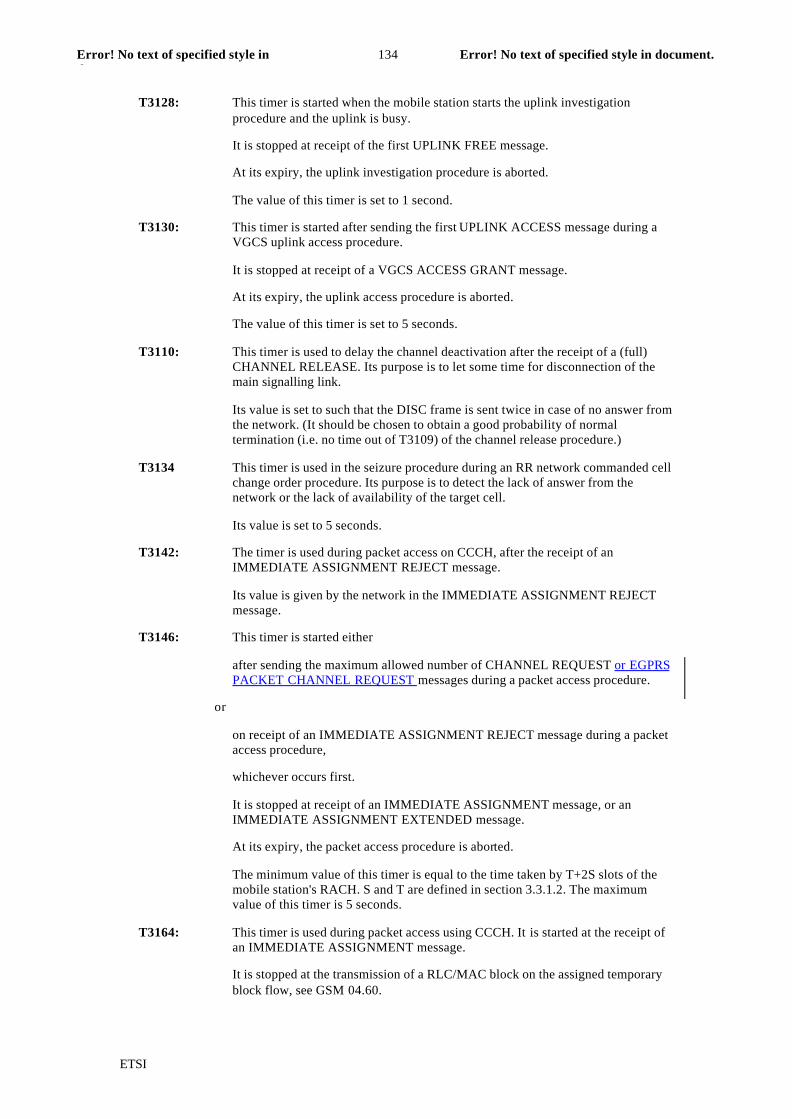
T3146: This timer is started either
after sending the maximum allowed number of CHANNEL REQUEST or EGPRSPACKET CHANNEL REQUEST messages during a packet access procedure.
or
on receipt of an IMMEDIATE ASSIGNMENT REJECT message during a packetaccess procedure,
whichever occurs first.
It is stopped at receipt of an IMMEDIATE ASSIGNMENT message, or anIMMEDIATE ASSIGNMENT EXTENDED message.
At its expiry, the packet access procedure is aborted.
The minimum value of this timer is equal to the time taken by T+2S slots of themobile station's RACH. S and T are defined in section 3.3.1.2. The maximumvalue of this timer is 5 seconds.
T3164: This timer is used during packet access using CCCH. It is started at the receipt ofan IMMEDIATE ASSIGNMENT message.
It is stopped at the transmission of a RLC/MAC block on the assigned temporaryblock flow, see GSM 04.60.

ETSI
Error! No text of specified style in document.135Error! No text of specified style indocument.
At expire, the mobile station returns to the packet idle mode.
The value of the time r is 5 seconds.
T3190: The timer is used during packet downlink assignment on CCCH. It is started at thereceipt of an IMMEDIATE ASSIGNMENT message or of an PDCHASSIGNMENT COMMAND message when in dedicated mode.
It is stopped at the receipt of a RLC/MAC block on the assigned temporary blockflow, see GSM 04.60.
At expiry, the mobile station returns to the packet idle mode.
The value of the timer is 5 seconds.
ETSI
Error! No text of specified style in document.136Error! No text of specified style indocument.
SMG2 Meeting #35 Document
2-00-929
Revision of 857
Schaumburg, IL, USA, 3 - 7 April 2000 e.g. for 3GPP use the format TP-99xxx
or for SMG, use the format P-99-xxx
CHANGE REQUEST Please see embedded help file at the bottom of thispage for instructions on how to fill in this form correctly.
Current Version: 8.3.004.60 CR A624r6
GSM (AA.BB) or 3G (AA.BBB) specification number ↑ ↑ CR number as allocated by MCC support team
For submission to: SMG#31bis for approval X strategic (for SMG
list expected approval meeting # here↑
for information non-strategic X use only)
Form: CR cover sheet, version 2 for 3GPP and SMG The latest version of this form is available from: ftp://ftp.3gpp.org/Information/CR-Form-v2.doc
Proposed change affects: (U)SIM ME X UTRAN / Radio X Core Network
(at least one should be marked with an X)
Source: Nokia, Alcatel Date: April 2000
Subject: MS RAC impacts on One Phase and Two Phase Access procedures
Work item: EDGE
Category: F Correction Release: Phase 2
A Corresponds to a correction in an earlier release Release 96
(only one category B Addition of feature X Release 97

ETSI
Error! No text of specified style in document.137Error! No text of specified style indocument.
shall be marked C Functional modification of feature Release 98
with an X) D Editorial modification Release 99 X
Release 00
Reason forchange:
- The network needs information about MS radio access capabilities for efficientresource allocation. The amount of MS radio access capability information hasincreased that much that it usually does not fit in one uplink control message(PACKET RESOURCE REQUEST). The CR includes an improvement of EGPRSOne Phase and Two Phase Access procedures by introducing a mechanism and anew signalling message to provide the needed MS RAC information to the network.
- it is precised that upon receipt of a PACKET RESOURCE REQUEST, the network canestablish a TBF in GPRS or EGPRS TBF mode ;
- it is precised that upon receipt of an EGPRS PACKET CHANNEL REQUEST, thenetwork can establish a TBF in GPRS or EGPRS TBF mode.
Clauses affected: 7.1.2.2.1, 7.1.2.2.1a, 7.1.2.2.2, 7.1.2.2.3, 7.1.2.2.4, 7.1.2.3a, 7.1.3.1, 7.1.3.2.1,7.1.3.3, 11.2, 11.2.16, 11,2.28 11.2.29, 11.2.32, 12.24, 13.1
Other specs Other 3G core specifications → List of CRs:
affected: Other GSM corespecifications
→ List of CRs:
MS test specifications → List of CRs:
BSS test specifications → List of CRs:
O&M specifications → List of CRs:
Othercomments:
help.doc
<--------- double-click here for help and instructions on how to create a CR.
ETSI
Error! No text of specified style in document.138Error! No text of specified style indocument.
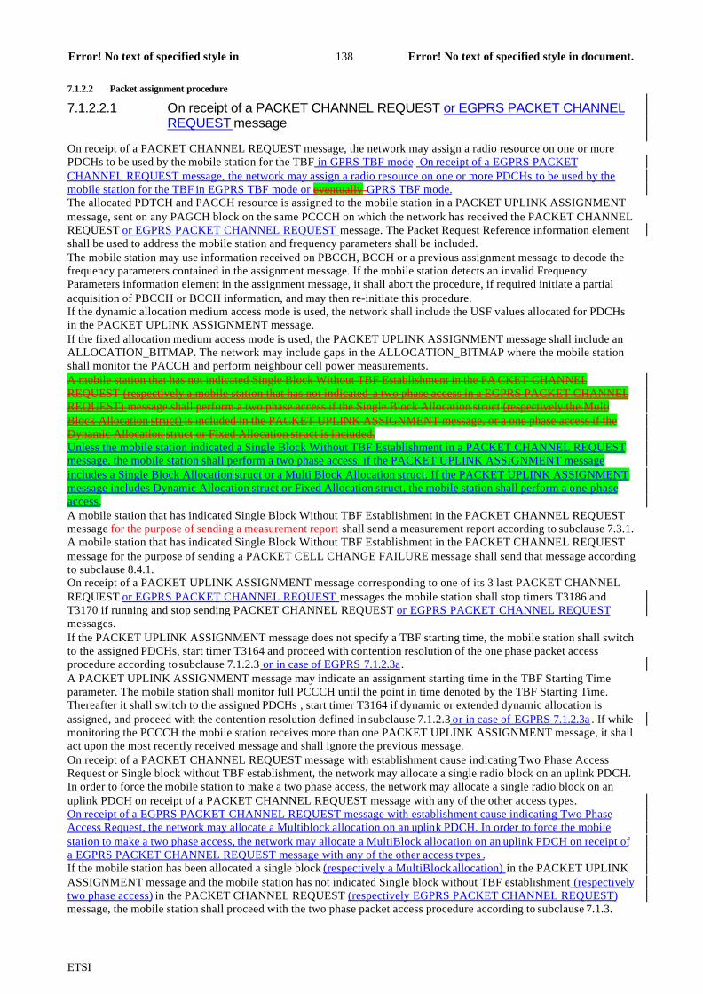
7.1.2.2 Packet assignment procedure
7.1.2.2.1 On receipt of a PACKET CHANNEL REQUEST or EGPRS PACKET CHANNELREQUEST message
On receipt of a PACKET CHANNEL REQUEST message, the network may assign a radio resource on one or morePDCHs to be used by the mobile station for the TBF in GPRS TBF mode. On receipt of a EGPRS PACKETCHANNEL REQUEST message, the network may assign a radio resource on one or more PDCHs to be used by themobile station for the TBF in EGPRS TBF mode or eventually GPRS TBF mode.The allocated PDTCH and PACCH resource is assigned to the mobile station in a PACKET UPLINK ASSIGNMENTmessage, sent on any PAGCH block on the same PCCCH on which the network has received the PACKET CHANNELREQUEST or EGPRS PACKET CHANNEL REQUEST message. The Packet Request Reference information elementshall be used to address the mobile station and frequency parameters shall be included.The mobile station may use information received on PBCCH, BCCH or a previous assignment message to decode thefrequency parameters contained in the assignment message. If the mobile station detects an invalid FrequencyParameters information element in the assignment message, it shall abort the procedure, if required initiate a partialacquisition of PBCCH or BCCH information, and may then re-initiate this procedure.If the dynamic allocation medium access mode is used, the network shall include the USF values allocated for PDCHsin the PACKET UPLINK ASSIGNMENT message.If the fixed allocation medium access mode is used, the PACKET UPLINK ASSIGNMENT message shall include anALLOCATION_BITMAP. The network may include gaps in the ALLOCATION_BITMAP where the mobile stationshall monitor the PACCH and perform neighbour cell power measurements.A mobile station that has not indicated Single Block Without TBF Establishment in the PA CKET CHANNELREQUEST (respectively a mobile station that has not indicated a two phase access in a EGPRS PACKET CHANNELREQUEST) message shall perform a two phase access if the Single Block Allocation struct (respectively the MultiBlock Allocation struct) is included in the PACKET UPLINK ASSIGNMENT message, or a one phase access if theDynamic Allocation struct or Fixed Allocation struct is included.Unless the mobile station indicated a Single Block Without TBF Establishment in a PACKET CHANNEL REQUESTmessage, the mobile station shall perform a two phase access, if the PACKET UPLINK ASSIGNMENT messageincludes a Single Block Allocation struct or a Multi Block Allocation struct. If the PACKET UPLINK ASSIGNMENTmessage includes Dynamic Allocation struct or Fixed Allocation struct, the mobile station shall perform a one phaseaccess.A mobile station that has indicated Single Block Without TBF Establishment in the PACKET CHANNEL REQUESTmessage for the purpose of sending a measurement report shall send a measurement report according to subclause 7.3.1.A mobile station that has indicated Single Block Without TBF Establishment in the PACKET CHANNEL REQUESTmessage for the purpose of sending a PACKET CELL CHANGE FAILURE message shall send that message accordingto subclause 8.4.1.On receipt of a PACKET UPLINK ASSIGNMENT message corresponding to one of its 3 last PACKET CHANNELREQUEST or EGPRS PACKET CHANNEL REQUEST messages the mobile station shall stop timers T3186 andT3170 if running and stop sending PACKET CHANNEL REQUEST or EGPRS PACKET CHANNEL REQUESTmessages.If the PACKET UPLINK ASSIGNMENT message does not specify a TBF starting time, the mobile station shall switchto the assigned PDCHs, start timer T3164 and proceed with contention resolution of the one phase packet accessprocedure according to subclause 7.1.2.3 or in case of EGPRS 7.1.2.3a.A PACKET UPLINK ASSIGNMENT message may indicate an assignment starting time in the TBF Starting Timeparameter. The mobile station shall monitor full PCCCH until the point in time denoted by the TBF Starting Time.Thereafter it shall switch to the assigned PDCHs , start timer T3164 if dynamic or extended dynamic allocation isassigned, and proceed with the contention resolution defined in subclause 7.1.2.3 or in case of EGPRS 7.1.2.3a . If whilemonitoring the PCCCH the mobile station receives more than one PACKET UPLINK ASSIGNMENT message, it shallact upon the most recently received message and shall ignore the previous message.On receipt of a PACKET CHANNEL REQUEST message with establishment cause indicating Two Phase AccessRequest or Single block without TBF establishment, the network may allocate a single radio block on an uplink PDCH.In order to force the mobile station to make a two phase access, the network may allocate a single radio block on anuplink PDCH on receipt of a PACKET CHANNEL REQUEST message with any of the other access types.On receipt of a EGPRS PACKET CHANNEL REQUEST message with establishment cause indicating Two PhaseAccess Request, the network may allocate a Multiblock allocation on an uplink PDCH. In order to force the mobilestation to make a two phase access, the network may allocate a MultiBlock allocation on an uplink PDCH on receipt ofa EGPRS PACKET CHANNEL REQUEST message with any of the other access types .If the mobile station has been allocated a single block (respectively a MultiBlock allocation) in the PACKET UPLINKASSIGNMENT message and the mobile station has not indicated Single block without TBF establishment (respectivelytwo phase access) in the PACKET CHANNEL REQUEST (respectively EGPRS PACKET CHANNEL REQUEST)message, the mobile station shall proceed with the two phase packet access procedure according to subclause 7.1.3.

ETSI
Error! No text of specified style in document.139Error! No text of specified style indocument.
If the mobile station has been allocated a single block in the PACKET UPLINK ASSIGNMENT message and themobile station has indicated Single block without TBF establishment in the PACKET CHANNEL REQUEST message,the mobile station shall proceed with the measurement report according to subclause 7.3.1.7.1.2.2.1a Acquisition of MS Radio Access Capability information within EGPRS TBF establishment procedureWhen assigning an EGPRS TBF, the network may request information about radio access capabilities of the mobilestation on one or several frequency bands within the PACKET UPLINK ASSIGNMENT message ; the list of frequencybands is ordered by the network starting with the most important and ending with the least important one . The mobilestation shall provide the network with its radio access capabilities for the frequency bands it supports, in the samepriority order as the one specified by the network, by sending a PACKET RESOURCE REQUEST message, and anADDITIONAL MS RADIO ACCESS CAPABILITIES if all the requested informations do not fit in the PACKETRESOURCE REQUEST. If the mobile station does not support any frequency band requested by the network, it shallreport its radio access capabilities for the BCCH frequency band. The mobile station shall indicate in the PACKETRESOURCE REQUEST if it will send more information about its radio access capabilities in the ADDITIONAL MSRADIO ACCESS CAPABILITIES message. The PACKET RESOURCE REQUEST and the ADDITIONAL MSRADIO ACCESS CAPABILITIES shall be sent within the one or two first radio blocks allocated for the mobile stationon the assigned PDCH. The mobile station shall include the TLLI in these two messages until contention resolution.After that, the mobile station shall use the uplink TFI whenever these messages are repeated. In case the TBF is shorterthan 40 radio blocks then the PACKET RESOURCE REQUEST and the ADDITIONAL MS RADIO ACCESSCAPABILITIES messages shall not be sent. The number of radio blocks shall be calculated assuming channel codingscheme MCS-1.In case the initial TBF is shorter than 40 radio blocks and the mobile station recognises later that it has more data to besent and the number of radio blocks within the TBF now exceeds 40 radio blocks, then the mobile station shall send thePACKET RESOURCE REQUEST and the ADDITIONAL RADIO ACCESS CAPABILITIES messages , providedthese were requested by the network. The messages shall be sent in the earliest possible radio blocks after the mobilestation recognises that the limit has been exceeded.NOTE: When constructing the PACKET RESOURCE REQUEST and ADDITIONAL MS RADIO ACCESSCAPABILITIES messages the mobile station shall take care that these messages fit in one UL radio block each. Thiscan be done by excluding circuit switched specific parameters from the MS Radio Access Capabilities IE (HSCSDmultislot class, ECSD multislot class).The network may request a retransmission of the PACKET RESOURCE REQUEST and the ADDITIONAL MSRADIO ACCESS CAPABILITIES messages. A request for retransmission of one or both of these messages shall beindicated in the PACKET UPLINK ACK/NACK message. The mobile station has to indicate within the PACKETRESOURCE REQUEST if the message is a retransmitted one.When sending a PACKET RESOURCE REQUEST the mobile station shall start the timer T3198. In case anADDITIONAL MS RADIO ACCESS CAPABILITIES message is sent then another instance of the timer T3198 shallbe started. The network may indicate in a PACKET UPLINK ACK/NACK message a request for retransmission of thePACKET RESOURCE REQUEST and/or the ADDITIONAL MS RADIO ACCESS CAPABILITIES messages. Themobile station has to indicate within the PACKET RESOURCE REQUEST if the message is a retransmitted one. If thePACKET UPLINK ACK/NACK message is received before the timer T3198 for the PACKET RESOURCEREQUEST or the ADDITIONAL MS RADIO ACCESS CAPABILITIES messages expires, then the request forretransmission for these messages shall be ignored. In case the PACKET UPLINK ACK/NACK is received by the MSafter the expiry of the timer T3198 and the message indicates a retransmission of either of the messages, then the MSshall retransmit the requested messages, provided they were sent earlier.
7.1.2.2.2 Packet access queuing notification procedure
The network may send to the mobile station a PACKET QUEUING NOTIFICATION message. The PACKETQUEUING NOTIFICATION message shall be sent on the same PCCCH on which the network has received thePACKET CHANNEL REQUEST or EGPRS PACKET CHANNEL REQUEST message. It contains a TemporaryQueuing Identity which is later used to identify the mobile station (either when polling or sending an assignment).On receipt of a PACKET QUEUING NOTIFICATION message corresponding to one of its 3 last PACKETCHANNEL REQUEST or EGPRS PACKET CHANNEL REQUEST messages, the mobile station shall stop timersT3170 and T3186 if running, start timer T3162, and stop sending PACKET CHANNEL REQUEST or EGPRSPACKET CHANNEL REQUEST messages. It shall continue to listen to the full PCCCH corresponding to itsPCCCH_GROUP. If the mobile station receives a PACKET QUEUING NOTIFICATION message while waiting forthe TBF Starting Time of a valid PACKET UPLINK ASSIGNMENT message, the mobile station shall ignore thePACKET QUEUEING NOTIFICATION.The network may send to the mobile station a PACKET UPLINK ASSIGNMENT message following a PACKETQUEUING NOTIFICATION message. In this case, the reference address to the mobile station shall be the TemporaryQueuing Identity received in the PACKET QUEUING NOTIFICATION message.On receipt of a PACKET UPLINK ASSIGNMENT message following a PACKET QUEUING NOTIFICATIONmessage, the mobile station shall stop timer T3162 and follow the procedures defined in subclause 7.1.2.2.1.

ETSI
Error! No text of specified style in document.140Error! No text of specified style indocument.
At expiry of timer T3162, the packet access procedure shall be aborted and a packet access failure shall be indicated tothe upper layer and the mobile station shall return to packet idle mode.If the mobile station receives a PACKET DOWNLINK ASSIGNMENT message, it shall abort the packet accessqueuing notification procedure and respond to the PACKET DOWNLINK ASSIGNMENT message (see subclause7.2.1). The mobile station shall then attempt establishment of an uplink TBF using the procedures defined in subclause8.1.2.5.
7.1.2.2.3 Packet polling procedure
The network may send to the mobile station a PACKET POLLING REQUEST message, after having sent a PACKETQUEUING NOTIFICATION message. The PACKET POLLING REQUEST message shall be sent on the same PDCHon which the network has received the PACKET CHANNEL REQUEST or EGPRS PACKET CHANNEL REQUESTmessage. The mobile station shall be addressed by the Temporary Queuing Identity.On receipt of a PACKET POLLING REQUEST message, the mobile station shall respond to the network with thePACKET CONTROL ACKNOWLEDGEMENT message in the reserved uplink radio block specified by the RRBPfield. The reserved block is considered as a one block PACCH allocation.
7.1.2.2.4 Packet access reject procedure
The network may, as response to a PACKET CHANNEL REQUEST or EGPRS PACKET CHANNEL REQUESTmessage, send to the mobile station a PACKET ACCESS REJECT message on any PAGCH block on the same PCCCHon which the channel request message was received. This message contains the request reference with time of receptionof the PACKET CHANNEL REQUEST or EGPRS PACKET CHANNEL REQUEST message, and optionally aWAIT_INDICATION field in the Reject structure of the PACKET ACCESS REJECT message.On receipt of a PACKET ACCESS REJECT message containing a Reject structure addressed to the mobile station,where the Packet Request Reference in the Reject structure corresponds to one of its 3 last PACKET CHANNELREQUEST or EGPRS PACKET CHANNEL REQUEST messages,
- the mobile station shall stop timer T3186, stop sending PACKET CHANNEL REQUEST or EGPRS PACKETCHANNEL REQUEST messages, start timer T3172 with the value indicated in the WAIT_INDICATION field,start timer T3170 if it has not already been started and listen to the downlink PCCCH until timer T3170 expires.During this time, the mobile station shall ignore additional PACKET ACCESS REJECT messages, but onreception of any PACKET UPLINK ASSIGNMENT message corresponding to any other of its 3 last PACKETCHANNEL REQUEST or EGPRS PACKET CHANNEL REQUEST messages the mobile station shall stoptimers T3170 and T3172 if running, and follow the procedure defined in subclause 7.1.2.2.1.
- If no PACKET UPLINK ASSIGNMENT message is received before expiration of timer T3170, the mobilestation shall indicate a packet access failure to upper layer and return to packet idle mode (listening to its pagingchannel). As an option the mobile station may stop timer T3170, indicate a packet access failure to upper layerand return to packet idle mode as soon as it has received responses from the network on all, or in case more than3 were sent, the last 3 of its PACKET CHANNEL REQUEST or EGPRS PACKET CHANNEL REQUESTmessages.
- If an erroneous PACKET UPLINK ASSIGNMENT message (e.g. the mobile station has been assigned morePDCHs than it supports according to its multislot class) addressed to the mobile station is received beforeexpiration of timerT3170, the mobile station shall stop T3170 and act as stated in subclause 7.1.4.
- If the mobile station receives a PACKET DOWNLINK ASSIGNMENT message, it shall stop timer T3170 ifrunning and respond to the PACKET DOWNLINK ASSIGNMENT message (see subclause 7.2.1).
- The mobile station is not allowed to make a new attempt for packet access in the same cell until timer T3172expires, but may attempt packet access in an other cell after successful cell reselection for radio conditionsreasons (see GSM 05.08). A mobile station in class A or class B mode of operation may attempt to enter thededicated mode in the same cell before timer T3172 has expired. During the time T3172 is running, the mobilestation shall ignore all received PACKET PAGING REQUEST messages except paging request to trigger RRconnection establishment.
- The value of the WAIT_INDICATION field (i.e. timer T3172) relates to the cell from which it was received.
7.1.2.3 Contention resolution at one phase accessIn order to uniquely identify the mobile station when sending on uplink, the RLC Header is extended to include theTLLI of the mobile station until the contention resolution is completed on the mobile station side.. At sending of thefirst RLC data block, the mobile station shall stop timer T3164, set counter N3104 to 1, and start timer T3166.The counter N3104 shall be stepped each time the mobile station sends an RLC data block.

ETSI
Error! No text of specified style in document.141Error! No text of specified style indocument.
The network shall respond by including the TLLI in the PACKET UPLINK ACK/NACK message after the firstcorrectly received RLC data block that comprises the TLLI.The contention resolution is completed on the network side when the network receives a TLLI value identifying themobile station, as part of the contention resolution procedure on the TBF.The contention resolution is completed on the mobile station side when the mobile station receives a PACKETUPLINK ACK/NACK message with the same TLLI as the mobile station has included in the RLC header of the firstRLC data blocks. The mobile shall then stop timer T3166 and counter N3104.The contention resolution has failed on the mobile station side when the counter N3104 has reached its maximum value,or on expiry of timer T3166, or if the mobile station receives a PACKET UPLINK ACK/NACK message with the rightTFI but with another TLLI than the mobile station has included in the RLC header of the first RLC data blocks. Themobile station shall then reset the counter N3104, stop timer T3166 if not expired, immediately stop transmitting on thisTBF and reinitiate the packet access procedure unless it has already been repeated 4 times. In that case, TBF failure hasoccurred.7.1.2.3a Contention resolution at one phase access for EGPRS TBFsThe TLLI is used to uniquely identify a MS when sending on uplink.The first EGPRS radio blocks (each of them carrying one or two RLC Data Blocks) shall include the TLLI in the datapart until contention resolution. If the MCS selected for transmitting the TLLI is either MCS-7, MCS-8 or MCS-9(carrying two RLC Data Blocks), the TLLI shall be inserted in the data part of both RLC Data Blocks. The TLLI shallbe included in the PACKET RESOURCE REQUEST and the ADDITIONAL MS RADIO ACCESS CAPABILITIESmessages in case contention resolution is not completed.Retransmissions will occur only after the contention resolution is completed on both network and mobile station sides.The retransmissions of the corrupted data blocks which contained the TLLI shall still include the TLLI, as the networkmay use IR and/or soft-combination. The retransmission of a data block which contained the TLLI shall still indicatewith the TI field, the presence of TLLI, as the network has to separate data octets from TLLI octets.At sending of the very first EGPRS radio block, the MS shall stop timer T3164, set counter N3104 to 1, and start timerT3166.The counter N3104 shall be stepped each time the MS sends an EGPRS radio block.The network shall respond by including the TLLI in the PACKET UPLINK ACK/NACK message after the firstcorrectly received EGPRS RLC block that comprises the TLLI.The contention resolution is completed on the network side when the network receives a TLLI value identifying themobile station, as part of the contention resolution procedure on the TBF.The contention resolution is completed on the mobile station side when the mobile station receives a PACKETUPLINK ACK/NACK message with the same TLLI as the mobile station has included in the data part of the firstEGPRS radio blocks. The mobile shall then stop timer T3166 and counter N3104.The contention resolution has failed on the mobile station side when the counter N3104 has reached its maximum value,or on expiry of timer T3166, or if the mobile station receives a PACKET UPLINK ACK/NACK message with the rightTFI but with another TLLI than the mobile station has included in the data part of the first EGPRS radio blocks. Themobile station shall then reset the counter N3104, stop timer T3166 if not expired, immediately stop transmitting on thisTBF and reinitiate the packet access procedure unless it has already been repeated 4 times. In that case, TBF failure hasoccurred.7.1.2.4 One phase packet access completionThe one phase packet access procedure is completed upon a successful contention resolution. The mobile station hasentered the packet transfer mode.7.1.2.5 Timing AdvanceInitial timing advance may be provided in the PACKET UPLINK ASSIGNMENT in theTIMING_ADVANCE_VALUE field.Thereafter either the timing advance is updated with a PACKET POWER CONTROL/TIMING ADVANCE messageor a continuous timing advance procedure is used. If a Timing Advance Index is included in the assignment message,the mobile station shall use the continuous update timing advance mechanism, using its allocation on PTCCH (seeGSM 05.10). Otherwise, the continuous update timing advance mechanism shall not be used. For the case where aTIMING_ADVANCE_VALUE field is not provided in the assignment message, the mobile station is not allowed tosend normal bursts on the uplink until it receives a valid timing advance either through the continuous timing advanceprocedure or in a PACKET POWER CONTROL/TIMING ADVANCE message.7.1.3 TBF establishment using twophase accessThe two phase access procedure defined in this subclause, is applicable also in the case when no PCCCH is provided inthe cell. For that case, the first phase is defined in GSM 04.08.7.1.3.1 Initiation of the Packet resource request procedureIn the first phase of a two phase access in a cell provided with a PCCCH, the same procedures as for one phase accessare used until the network sends a PACKET UPLINK ASSIGNMENT message including a Single Block Allocationstruct or Multi Block Allocation struct, denoting two phase access to the mobile station. Multi Block Allocation structdenotes two phase access in EGPRS mode. In that message, the network reserves a limited resource on one PDCH to

ETSI
Error! No text of specified style in document.142Error! No text of specified style indocument.
the mobile station where the mobile station transmits a PACKET RESOURCE REQUEST message and optionally anADDITIONAL MS RADIO ACCESS CAPABILITIES message.If PCCCH is provided in the cell, a two phase access can be initiated:
- by the network by ordering the mobile station to send a PACKET RESOURCE REQUEST message. The orderis sent implicitly to the mobile station in the PACKET UPLINK ASSIGNMENT message by including either theSingle Block Allocation struct or Multi Block Allocation struct.
- by a mobile station, by requiring a two phase access in the PACKET CHANNEL REQUEST or EGPRSPACKET CHANNEL REQUEST message. In this case, if access is granted, the network shall order the mobilestation to send a PACKET RESOURCE REQUEST message. The order is sent implicitly to the mobile station inthe PACKET UPLINK ASSIGNMENT message by including the Single Block Allocation Struct or Multi BlockAllocation struct.
If no PCCCH is provided in the cell, a two phase access can be initiated:- by the network or by a mobile station, as defined in GSM 04.08.
When the mobile station has received a PACKET UPLINK ASSIGNMENT message it shall respond with a PACKETRESOURCE REQUEST message in the first allocated single radio block. At sending of the PACKET RESOURCEREQUEST message, the mobile station shall start timer T3168. Further more, the mobile station shall not respond toPACKET DOWNLINK ASSIGNMENT messages while timer T3168 is running.The mobile station may request an open-ended or a close-ended TBF. If a close-ended TBF is requested, the number ofoctets of user data that the MS has to transfer in the TBF shall be indicated in the PACKET RESOURCE REQUESTmessage. 7.1.3.2 Packet resource assignment for uplink procedureWhen assigning a multiblock packet access, the network may request information about radio access capabilities of themobile station on one or several frequency bands within the PACKET UPLINK ASSIGNMENT message and allocateone or two radio blocks for uplink control messages accordingly ; the list of frequency bands is ordered by the networkstarting with the most important and ending with the least important one. The mobile station shall then provide thenetwork with its radio access capabilities for the frequency bands it supports, in the same priority order as the onespecified by the network, by sending a PACKET RESOURCE REQUEST message in the first radio block on theassigned PDCH, and an ADDITIONAL MS RADIO ACCESS CAPABILITIES immediately after the PACKETRESOURCE REQUEST message on the assigned PDCH if all the requested informations do not fit in the PACKETRESOURCE REQUEST and two radio blocks have been allocated by the network. If the mobile station does notsupport any frequency band requested by the network, it shall report its radio access capabilities for the BCCHfrequency band in the PACKET RESOURCE REQUEST message. The mobile station shall indicate in the PACKETRESOURCE REQUEST if it will send more information about its radio access capabilities in the ADDITIONAL MSRADIO ACCESS CAPABILITIES message. If the mobile station has been allocated two radio blocks and all therequested informations fit in the PACKET RESOURCE REQUEST message, no ADDITIONAL MS RADIO ACCESSCAPABILITIES message shall be sent. Instead, some uplink control block (e.g. packet measurement report, packetuplink dummy control block) mayshall be sent by the mobile station.At sending of the ADDITIONAL RADIO ACCESS CAPABILITIES message, the mobile station shall start the timerT3198. The network may indicate in the next PACKET UPLINK ASSIGNMENT message a request for retransmissionof the ADDITIONAL MS RADIO ACCESS CAPABILITIES message, see section 7.1.3.2.1. If a retransmission of theADDITIONAL RADIO ACCESS CAPABILTIES message is requested when the timer T3198 is running, then therequest shall be ignored. If the network requests a retransmission of the ADDITIONAL RADIO ACCESSCAPABILITIES message after expiry of the timer T3198, then the mobile station shall retransmit the message,provided that it was sent earlier.NOTE: When constructing the PACKET RESOURCE REQUEST and ADDITIONAL MS RADIO ACCESSCAPABILITIES messages the mobile station shall take care that these messages fit in one UL radio block each. Thiscan be done by excluding circuit switched specific parameters from the MS Radio Access Capabilities IE (HSCSDmultislot class, ECSD multislot class).
7.1.3.2.1 On receipt of a PACKET RESOURCE REQUEST message
On receipt of a PACKET RESOURCE REQUEST message scheduled with a Single Block or MultiBlock allocation,the network shall respond by sending a PACKET UPLINK ASSIGNMENT (radio resources assignment on one or morePDCHs to be used by the mobile station for the TBF in EGPRS or GPRS TBF mode) or a PACKET ACCESS REJECTmessage to the mobile station on PACCH on the same PDCH on which the mobile station has sent the PACKETRESOURCE REQUEST message.For an EGPRS two-phase acces request , on receipt of a PACKET RESOURCE REQUEST message indicating noADDITIONAL MS RADIO ACCESS CAPABILITIES message, the same procedure as described previously shallapply.For an EGPRS two-phase access request, on receipt of a PACKET RESOURCE REQUEST message indicating anADDITIONAL MS RADIO ACCESS CAPABILITIES message, the network shall respond by sending a PACKET

ETSI
Error! No text of specified style in document.143Error! No text of specified style indocument.
UPLINK ASSIGNMENT message after reception of the ADDITIONAL MS RADIO ACCESS CAPABILITIESmessage.In case Depending on whether the ADDITIONAL MS RADIO ACCESS CAPABILITES message iswas not receivedcorrectly, the network can either :- send a PACKET UPLINK ASSIGNMENT message assigning radio resources on one or more PDCHs to be used
by the mobile station for the TBF in EGPRS or GPRS TBF mode, based on the information the network has got ;- send a PACKET UPLINK ASSIGNMENT message assigning radio resources on one or more PDCHs to be used
by the mobile station for the TBF in EGPRS TBF mode and request a retransmission of the ADDITIONAL MSRADIO ACCESS CAPABILITIES message ;
- send a PACKET UPLINK ASSIGNMENT message including a MultiBlock allocation struct (allocating only oneblock) requesting a retransmission of the ADDITIONAL MS RADIO ACCESS CAPABILITIES message ;
- send a PACKET ACCESS REJECT message to the mobile station. or not, either of the following procedures shall apply respectively:�The network shall respond by sending a PACKET UPLINK ASSIGNMENT (radio resources assignment on one or
more PDCHs to be used by the mobile station for the TBF in EGPRS or GPRS TBF mode) or a PACKETACCESS REJECT message to the mobile station on PACCH on the same PDCH as the one on which the mobilestation has sent the PACKET RESOURCE REQUEST message ;
The network shall respond by sending a PACKET UPLINK ASSIGNMENT assigning radio resources on one or morePDCHs to be used by the mobile station for the TBF in EGPRS or GPRS TBF mode, and for an EGPRS TBF byrequesting a retransmission of the ADDITIONAL MS RADIO ACCESS CAPABILITIES message, or a PACKETACCESS REJECT message to the mobile station on PACCH on the same PDCH as the one on which the mobilestation has sent the PACKET RESOURCE REQUEST message. The network may allocate alternatively a singleradio block to be used for retransmission of the ADDITIONAL MS RADIO ACCESS CAPABILITIES message.This is indicated by including a multi block structure and requesting a retransmission of the ADDITIONAL MSRADIO ACCESS CAPABILITIES message in a PACKET UPLINK ASSIGNMENT message.
On receipt of a PACKET UPLINK ASSIGNMENT message the mobile station shall switch to the assigned PDCHs.The mobile station may use information received on PBCCH, BCCH or a previous assignment message to decode thefrequency parameters contained in the assignment message. If the mobile station detects an invalid FrequencyParameters information element in the assignment message, it shall abort the procedure, if required initiate a partialacquisition of PBCCH or BCCH information, and may then re-initiate the access on the PRACH.On receipt of a PACKET ACCESS REJECT message that contains a Reject structure addressed to the mobile station,the mobile station shall stop timer T3168 and indicate a packet access failure to upper layer.If the PACKET ACCESS REJECT message contains a WAIT_INDICATION field in a Reject structure addressed tothe mobile station, the mobile station shall start timer T3172 with the indicated value (Wait Indication). The mobilestation is not allowed to make a new attempt for packet access in the same cell until timer T3172 expires, but mayattempt packet access in an other cell after successful cell reselection.On expiry of timer T3168, contention resolution has failed on the mobile station side. The mobile station shall thenreinitiate the packet access procedure unless it has already been repeated 4 times. In that case, TBF failure has occurredand an RLC/MAC error should be reported to the higher layer.7.1.3.3 Contention resolution at two phase accessThe contention resolution is completed on the network side when the network receives a TLLI value identifying themobile station, as part of the contention resolution procedure on the TBF.The contention resolution is completed on the mobile station side when the mobile station receives a PACKETUPLINK ASSIGNMENT message with the same TLLI as the mobile station has included in the PACKET RESOURCEREQUEST and ADDITIONAL MS RADIO ACCESS CAPABILITIES messages. The mobile station shall then stoptimer T3168. It does not include its TLLI in any RLC data block.The contention resolution has failed on the mobile station side when the mobile station does not receive a PACKETUPLINK ASSIGNMENT message with its TLLI before expiry of timer 3168. The mobile station shall then reinitiatethe packet access procedure unless it has already been repeated 4 times. In that case, TBF failure has occurred.7.1.3.4 Two phase packet access completionThe two phase packet access procedure is completed upon a successful contention resolution. The mobile station hasentered the packet transfer mode.7.1.3.5 Timing AdvanceIf a Timing Advance Index is included in the PACKET UPLINK ASSIGNMENT message, the mobile station shall usethe continuous update timing advance mechanism, using its allocation on PTCCH (see GSM 05.10). Otherwise, thecontinuous update timing advance mechanism shall not be used.For the case where a TIMING_ADVANCE_VALUE field is not provided in the assignment message, the mobilestation shall use its previous timing advance (either assigned in the previous IMMEDIATE ASSIGNMENT messagereceived on AGCH or in the previous PACKET UPLINK ASSIGNMENT message received on PAGCH, or got throughthe continuous timing advance procedure).

ETSI
Error! No text of specified style in document.144Error! No text of specified style indocument.
Otherwise, the mobile station is not allowed to send normal bursts on the uplink until it receives a valid timing advanceeither through the continuous timing advance procedure or in a PACKET TIMING ADVANCE/POWER CONTROLmessage.7.1.4 Abnormal casesIf a failure occurs on the mobile station side of the new TBF before mobile station has successfully entered the packettransfer mode, the newly reserved resources are released; the subsequent behaviour of the mobile station depends on thetype of failure and previous actions.
- If the failure is due to a TLLI mismatch, or to the expiry of timers T3166 or T3168, or to the fact that the counterN3104 reaches its maximum value in the contention resolution procedure, and repetition as described insubclauses 7.1.2.3, 7.1.3.2.1 or 7.1.3.3 has been performed, the mobile station shall remain in packet idle mode,notify higher layer (TBF establishment failure), transactions in progress shall be aborted and cell reselectioncontinued, unless the failure takes place during a RR-cell change order procedure, in which case the mobilebehaviour shall be as described in the Abnormal cases of the RR-Network Commanded Cell Change OrderProcedure in GSM 04.08.
- If the mobile station has been assigned more PDCHs than it supports according to its MS multislot class, themobile station shall reinitiate the packet access procedure unless it has already been repeated 4 times. In thatcase, TBF failure has occurred.
- If the mobile station has been assigned a TBF in EGPRS mode and the MS does not support EGPRS, or has beenassigned an MCS (e.g. 8-PSK in the Uplink) that the MS does not support, the MS shall return to packet idlemode and notify higher layers (TBF establishment failure)
- On expiry of timer T3164, the mobile station shall reinitiate the packet access procedure unless it has alreadybeen reinitiated 3 times, in which case the mobile station shall return to packet idle mode and notify higherlayers (TBF establishment failure).
- If the failure is due to any other reason, the mobile station shall return to packet idle mode, notify higher layer(TBF establishment failure), transactions in progress shall be aborted and cell reselection continues.
ETSI
Error! No text of specified style in document.145Error! No text of specified style indocument.
11.2 RLC/MAC control messagesTable 1 summarises the RLC/MAC control messages. For each control message, the message type shall be a fixednumber of bits from the beginning of the message.

ETSI
Error! No text of specified style in document.146Error! No text of specified style indocument.
Table 1: RLC/MAC control messages
Uplink TBF establishment messages: Reference
P`acket Access Reject 11.2.1Packet Channel Request 11.2.5EGPRS Packet Channel Request 11.2.5aPacket Queuing Notification 11.2.15Packet Resource Request 11.2.16Packet Uplink Assignment 11.2.29Additional MS Radio Access Capabilities 11.2.32
Downlink TBF establishment messages: Reference
Packet Downlink Assignment 11.2.7
TBF release messages: Reference
Packet TBF Release 11.2.26
Paging messages: Reference
Packet Paging Request 11.2.10
RLC messages: Reference
Packet Downlink Ack/Nack 11.2.6EGPRS Packet Downlink Ack/Nack 11.2.6aPacket Uplink Ack/Nack 11.2.28
System information messages: Reference
Packet System Information Type 1 11.2.18Packet System Information Type 2 11.2.19Packet System Information Type 3 11.2.20Packet System Information Type 3 bis 11.2.21Packet System Information Type 4 11.2.22Packet System Information Type 5 11.2.23Packet System Information Type 6 11.2.23aPacket System Information Type 7 11.2.23bPacket System Information Type 13 11.2.25
Miscellaneous messages: Reference
Packet Control Acknowledgement 11.2.2Packet Cell Change Failure 11.2.3Packet Cell Change Order 11.2.4Packet Downlink Dummy Control Block 11.2.8Packet Uplink Dummy Control Block 11.2.8bPacket Measurement Report 11.2.9Packet Measurement Order 11.2.9bPacket Mobile TBF Status 11.2.9cPacket PDCH Release 11.2.11Packet Polling Request 11.2.12Packet Power Control/Timing Advance 11.2.13Packet PRACH Parameters 11.2.14Packet PSI Status 11.2.17Spare 11.2.24Spare 11.2.27Spare 11.2.30Packet Pause 11.2.30aPacket Timeslot Reconfigure 11.2.31
11.2.0 Message formatAll RLC/MAC control messages, with the exception of the PACKET CONTROL ACKNOWLEDGEMENT messagein access burst format (11-bit and 8-bit contents) and the PACKET CHANNEL REQUEST message, follow the samenon-standard format (see GSM 04.07).

ETSI
Error! No text of specified style in document.147Error! No text of specified style indocument.
11.2.0.2 Uplink RLC/MAC messagesUplink RLC/MAC control messages, except those using the access burst formats, are received in the RLC/MAC controlblock format. The different types of messages are distinguished by the MESSAGE_TYPE field.
< Uplink RLC/MAC control message > ::=< MESSAGE_TYPE : bit (6) == 000000 > < Packet Cell Change Failure message content > |< MESSAGE_TYPE : bit (6) == 000001 >
< Packet Control Acknowledgement message content > |< MESSAGE_TYPE : bit (6) == 000010 > < Packet Downlink Ack/Nack message content > |< MESSAGE_TYPE : bit (6) == 000011 >
< Packet Uplink Dummy Control Block message content > |< MESSAGE_TYPE : bit (6) == 000100 > < Packet Measurement Report message content > |< MESSAGE_TYPE : bit (6) == 000101 > < Packet Resource Request message content > |< MESSAGE_TYPE : bit (6) == 000110 > < Packet Mobile TBF Status message content > |< MESSAGE_TYPE : bit (6) == 000111 > < Packet PSI Status message content > |< MESSAGE_TYPE : bit (6) == 001000 > < EGPRS Packet Downlink Ack/Nack message content
> | < MESSAGE_TYPE : bit (6) == 001001 > < Packet Pause message content > | < MESSAGE_TYPE : bit (6) == 001010 > < Additional MS Radio Access Capabilities messagecontent> ;
Messages using the access burst formats (11-bit and 8-bit formats) are defined in clauses 11.2.2 and 11.2.5.
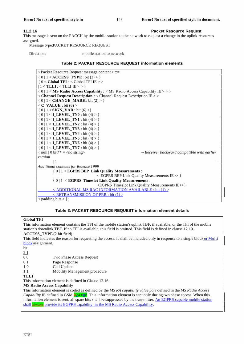
ETSI
Error! No text of specified style in document.148Error! No text of specified style indocument.
11.2.16 Packet Resource RequestThis message is sent on the PACCH by the mobile station to the network to request a change in the uplink resourcesassigned.
Message type:PACKET RESOURCE REQUEST
Direction: mobile station to network
Table 2: PACKET RESOURCE REQUEST information elements
< Packet Resource Request message content > ::={ 0 | 1 < ACCESS_TYPE : bit (2) > }{ 0 < Global TFI : < Global TFI IE > >| 1 < TLLI : < TLLI IE > > }{ 0 | 1 < MS Radio Access Capability : < MS Radio Access Capability IE > > }< Channel Request Description : < Channel Request Description IE > >{ 0 | 1 < CHANGE_MARK : bit (2) > }< C_VALUE : bit (6) >{ 0 | 1 < SIGN_VAR : bit (6) >}{ 0 | 1 < I_LEVEL_TN0 : bit (4) > }{ 0 | 1 < I_LEVEL_TN1 : bit (4) > }{ 0 | 1 < I_LEVEL_TN2 : bit (4) > }{ 0 | 1 < I_LEVEL_TN3 : bit (4) > }{ 0 | 1 < I_LEVEL_TN4 : bit (4) > }{ 0 | 1 < I_LEVEL_TN5 : bit (4) > }{ 0 | 1 < I_LEVEL_TN6 : bit (4) > }{ 0 | 1 < I_LEVEL_TN7 : bit (4) > }{ null | 0 bit** = <no string> -- Receiver backward compatible with earlierversion
| 1 --Additional contents for Release 1999
{ 0 | 1 < EGPRS BEP Link Quality Measurements :< EGPRS BEP Link Quality Measurements IE>> }
{ 0 | 1 < EGPRS Timeslot Link Quality Measurements :<EGPRS Timeslot Link Quality Measurements IE>>}
< ADDITIONAL MS RAC INFORMATION AVAILABLE : bit (1) > < RETRANSMISSION OF PRR : bit (1) >< padding bits > };
Table 3: PACKET RESOURCE REQUEST information element details
Global TFIThis information element contains the TFI of the mobile station's uplink TBF, if available, or the TFI of the mobilestation's downlink TBF. If no TFI is available, this field is omitted. This field is defined in clause 12.10.ACCESS_TYPE (2 bit field)This field indicates the reason for requesting the access. It shall be included only in response to a single block or Multiblock assignment.bit2 10 0 Two Phase Access Request0 1 Page Response1 0 Cell Update1 1 Mobility Management procedureTLLIThis information element is defined in Clause 12.16.MS Radio Access CapabilityThis information element is coded as defined by the MS RA capability value part defined in the MS Radio AccessCapability IE defined in GSM 024.008. This information element is sent only during two phase access. When thisinformation element is sent, all spare bits shall be suppressed by the transmitter. An EGPRS capable mobile stationshall always provide its EGPRS capability in the MS Radio Access Capability.

ETSI
Error! No text of specified style in document.149Error! No text of specified style indocument.
Table 3 (continued): PACKET RESOURCE REQUEST information element details
Channel Request DescriptionThis information element is defined in clause 12.7.CHANGE_MARK (2 bit field)This field contains the PSI2_CHANGE_MARK value stored by the mobile station's if PBCCH is present in the currentcell. If PBCCH is not present in the current cell, this field contains the SI13_CHANGE_MARK value stored by themobile station. If the mobile station does not have a valid PSI2 or SI13 change mark for the current cell, the mobilestation shall omit this field. The coding of this field is network dependent.C_VALUE (6 bit field)This field is encoded as the binary representation of the C value as specified in GSM 05.08.Range 0 to 63SIGN_VAR (6 bits)This field contains the signal variance parameter SIGN_VAR calculated by the mobile station (see GSM 05.08). Thisfield is not present for TBF establishment using two phase access or for a TBF in EGPRS mode. bit6 5 4 3 2 10 0 0 0 0 0 0dB2 to 0.25 dB2
0 0 0 0 0 1 >0.25 dB2 to 0.50 dB2
0 0 0 0 1 0 >0.50 dB2 to 0.75 dB2
: : :1 1 1 1 1 0 >15.50 dB2 to 15.75 dB2
1 1 1 1 1 1 >15.75 dB2
I_LEVEL_TN0 (4 bit field)I_LEVEL_TN1 (4 bit field)I_LEVEL_TN2 (4 bit field)I_LEVEL_TN3 (4 bit field)I_LEVEL_TN4 (4 bit field)I_LEVEL_TN5 (4 bit field)I_LEVEL_TN6 (4 bit field)I_LEVEL_TN7 (4 bit field)For element definition see subclause 11.2.6 – Packet Downlink Ack/Nack.
EGPRS BEP Link Quality Measurements IEThis information element is defined in clause 12.5.3. These fields are transferred if the data is available and if the fieldswould not cause the message to expand beyond one RLC/MAC control block and if the PACKET RESOURCEREQUEST is sent during an on-going EGPRS TBF or during a two phase access in EGPRS mode.EGPRS Timeslot Link Quality MeasurementsThis information element is defined in clause 12.5.4. These fields are transferred if the data is available and if the fieldswould not cause the message to expand beyond one RLC/MAC control block and if the PACKET RESOURCEREQUEST is sent during an on-going EGPRS TBF or during a two phase access in EGPRS mode.
ADDITIONAL MS RAC INFORMATION AVAILABLE (1 bit field)0 indicates that MS will not send more information about its radio access capabilities than included in this message1 indicates that MS will send more information about its radio access capabilities in the next control message
RETRANSMISSION OF PRR (1 bit field)This field indicates whether the corresponding Packet Resource Request message is a retransmission. In case the PRRmessage is a retransmission, the message content (except this field) shall be identical to the one of the PRR which wassent immediately after the uplink TBF was established (and preceding any eventual request for resource reassignment).
0 indicates that this message is an initial Packet Resource Request1 indicates that this message is a retransmitted Packet Resource Request: in this case the corresponding PRRmessage shall not be interpreted as a request for resource reassignment.

ETSI
Error! No text of specified style in document.150Error! No text of specified style indocument.
11.2.28 Packet Uplink Ack/NackThis message is sent on the PACCH by the network to the mobile station indicate the status of the received RLC datablocks. This message may also update the timing advance and power control parameters. A fixed allocation mobilestation may also be assigned uplink resources.
Message type:PACKET UPLINK ACK/NACK
Direction: network to mobile station
Classification:non-distribution message
Table 4: PACKET UPLINK ACK/NACK information elements
< Packet Uplink Ack/Nack message content > ::=< PAGE MODE : bit (2) >{ 00 < UPLINK_TFI : bit (5) >
{ 0 -- Message escape{ < CHANNEL_CODING_COMMAND : bit (2) >
< Ack/Nack Description : < Ack/Nack Description IE > >{ 0 | 1 < CONTENTION_RESOLUTION_TLLI : bit (32) > }{ 0 | 1 < Packet Timing Advance : < Packet Timing Advance IE > > }{ 0 | 1 < Power Control Parameters : < Power Control Parameters IE > > }{ 0 | 1 < Extension Bits : Extension Bits IE > } --
sub-clause 12.26{ 0 | 1 < Fixed Allocation Parameters : < Fixed Allocation struct > > }
{ null | 0 bit** = < no string > -- Receiver backward compatible with earlier version| 1 -- Additions for R99
{ 0 | 1 <Packet Extended Timing Advance : bit (2)>}< padding bits > }
! < Non-distribution part error : bit (*) = < no string > > }| 1 -- Message escape bit used to define EGPRS message contents
{ 00 { < EGPRS Channel Coding Command : < EGPRS Modulation andCoding IE >>
<Resegment : < Resegment IE >><PRE_EMPTIVE_TRANSMISSION : bit (1) >
< PRR RETRANSMISSION REQUEST : bit (1) > < ARAC RETRANSMISSION REQUEST : bit (1) >
{ 0 | 1 < CONTENTION_RESOLUTION_TLLI : bit (32) >}
{ 0 | 1 < Packet Timing Advance : < Packet Timing Advance IE > > }{ 0 | 1 <Packet Extended Timing Advance : bit (2)> }}
{ 0 | 1 < Power Control Parameters : < Power Control Parameters IE >> }
{ 0 | 1 < Extension Bits : Extension Bits IE > }-- sub-clause 12.26
{ < EGPRS Ack/Nack Description : < EGPRS Ack/Nack Description IE >> { 0 | 1 < Fixed Allocation Parameters : < Fixed Allocation struct > > } } //
< padding bits > ! < Non-distribution part error : bit (*) = < no string > > }
! < Message escape : {01| 10 | 11} bit (*) = <no string> > } } – Extended for future changes ! < Address information part error : bit (*) = < no string > > }
! < Distribution part error : bit (*) = < no string > > ;
< Fixed Allocation struct > ::=< FINAL_ALLOCATION : bit (1) >{ 0 -- Repeat Allocation
< TS_OVERRIDE : bit (8) >| 1 -- Allocation with Allocation bitmap
< TBF Starting Time : < Starting Frame Number Description IE > >{ 0 | 1 <TIMESLOT_ALLOCATION : bit (8) > }{ 0 { 0 -- with length of Allocation Bitmap
< BLOCKS_OR_BLOCK_PERIODS : bit (1) >
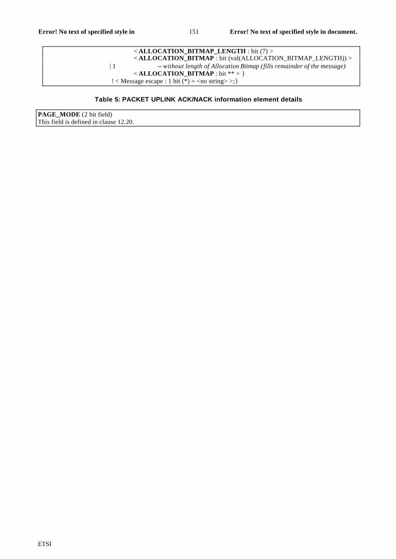
ETSI
Error! No text of specified style in document.151Error! No text of specified style indocument.
< ALLOCATION_BITMAP_LENGTH : bit (7) >< ALLOCATION_BITMAP : bit (val(ALLOCATION_BITMAP_LENGTH)) >
| 1 -- without length of Allocation Bitmap (fills remainder of the message)< ALLOCATION_BITMAP : bit ** > }
! < Message escape : 1 bit (*) = <no string> >;}
Table 5: PACKET UPLINK ACK/NACK information element details
PAGE_MODE (2 bit field)This field is defined in clause 12.20.

ETSI
Error! No text of specified style in document.152Error! No text of specified style indocument.
Table 5 (continued): PACKET UPLINK ACK/NACK information element details
UPLINK_TFI (5 bit field)This field identifies the uplink TBF to which this message applies. This field is coded the same as the TFI field definedin subclause 12.15.CHANNEL_CODING_COMMAND (2 bit field)The Channel Coding Indicator field indicates the channel coding scheme that the mobile station shall use whentransmitting on the uplink.bits2 1 value0 0 CS-10 1 CS-21 0 CS-31 1 CS-4Ack/Nack DescriptionThis information element is defined in subclause 12.3.EGPRS Modulation and Coding SchemeThe EGPRS Modulation and Coding Scheme information element is defined in clause 12.10d.RESEGMENTThe RESEGMENT information elemet is defined in clause 12.10e.PRE_EMPTIVE_TRANSMISSION (1 bit field)This bit informs the mobile station if it may or may not transmit the oldest RLC data block whose correspondingelement in V(B) has the value PENDING_ACK (and repeating the process, refter to clause 9.1.3.2) when the protocol isstalled or has no more RLC data blocks to transmit.0 The mobile station shall use pre-emptive tranmission.1 The mobile station shall not use pre-emptive transmission. PRR RETRANSMISSION REQUEST (1 bit field)0 indicates that retransmission of a PACKET RESOURCE REQUEST message is not requested1 indicates that retransmis sion of a PACKET RESOURCE REQUEST message is requested
ARAC RETRANSMISSION REQUEST (1 bit field)0 indicates that retransmission of an ADDITIONAL MS RADIO ACCESS CAPABILITIES message is notrequested1 indicates that retransmission of an ADDITIONAL MS RADIO ACCESS CAPABILITIES message isrequested
EGPRS Ack/Nack DescriptionThis information element is defined in subclause 12.3.1. The number of bits (L) available for Ack/Nack Descriptioninformation element depends on the inclusion of other information elements. L may be set so that the entire EGPRSPACKET UPLINK ACK/NACK message evenly fits into an RLC/MAC control block. If a lower L covers the entirereceive window, that L may be used.CONTENTION_RESOLUTION_TLLI (32 bit field)The CONTENTION_RESOLUTION_TLLI field is present only if the network has decoded one of the uplink RLC datablocks containing the TLLI. The mobile station shall perform the contention resolution function if the TLLI informationelement is present. This field contains a TLLI, which is defined in subclause 12.16.Packet Timing AdvanceThis information element is defined in subclause 12.12.TIMESLOT_ALLOCATION (8 bit field)This field is defined in subclause 12.18.Power Control ParametersThis information element, if present, contains power control command for the mobile station. If this informationelement is not present for certain previously allocated timeslots, the MS shall continue to use the previous power onthese timeslots. This information element is defined in subclause 12.13.Extension BitsThis information element, if present, shall be skipped over. Any information content shall be ignored by the mobilestation. This information element is defined in subclause 12.26.FINAL_ALLOCATION (1 bit field)This field indicates whether this allocation is the last allocation of the TBF.0 this allocation is not the last allocation of the TBF1 this allocation is the last allocation of the TBF
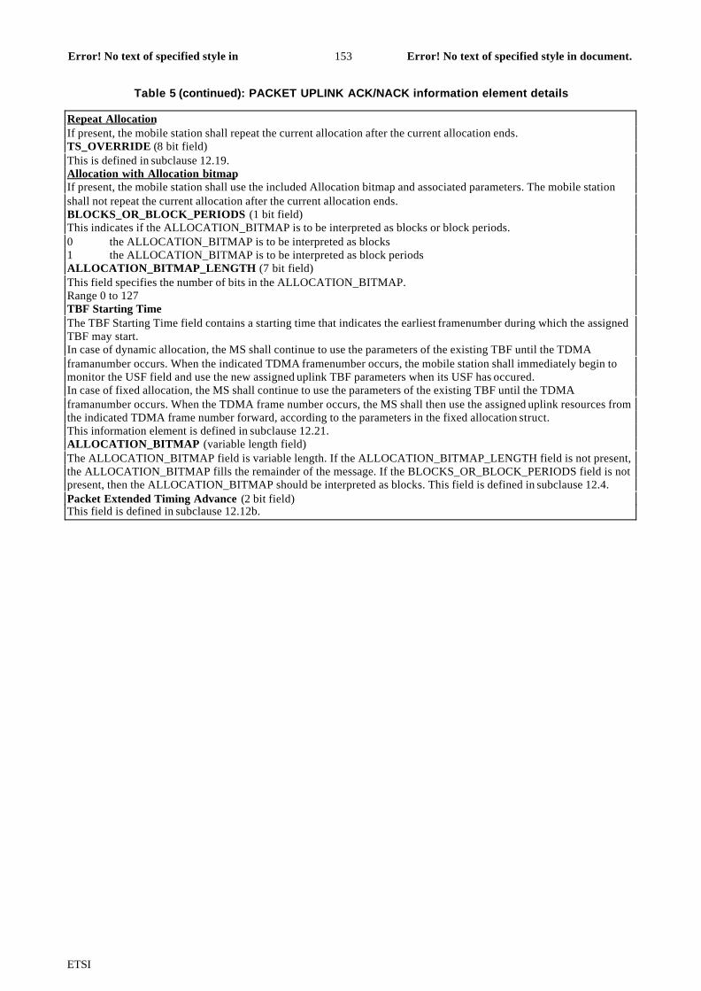
ETSI
Error! No text of specified style in document.153Error! No text of specified style indocument.
Table 5 (continued): PACKET UPLINK ACK/NACK information element details
Repeat AllocationIf present, the mobile station shall repeat the current allocation after the current allocation ends.TS_OVERRIDE (8 bit field)This is defined in subclause 12.19.Allocation with Allocation bitmapIf present, the mobile station shall use the included Allocation bitmap and associated parameters. The mobile stationshall not repeat the current allocation after the current allocation ends.BLOCKS_OR_BLOCK_PERIODS (1 bit field)This indicates if the ALLOCATION_BITMAP is to be interpreted as blocks or block periods.0 the ALLOCATION_BITMAP is to be interpreted as blocks1 the ALLOCATION_BITMAP is to be interpreted as block periodsALLOCATION_BITMAP_LENGTH (7 bit field)This field specifies the number of bits in the ALLOCATION_BITMAP.Range 0 to 127TBF Starting TimeThe TBF Starting Time field contains a starting time that indicates the earliest framenumber during which the assignedTBF may start.In case of dynamic allocation, the MS shall continue to use the parameters of the existing TBF until the TDMAframanumber occurs. When the indicated TDMA framenumber occurs, the mobile station shall immediately begin tomonitor the USF field and use the new assigned uplink TBF parameters when its USF has occured.In case of fixed allocation, the MS shall continue to use the parameters of the existing TBF until the TDMAframanumber occurs. When the TDMA frame number occurs, the MS shall then use the assigned uplink resources fromthe indicated TDMA frame number forward, according to the parameters in the fixed allocation struct.This information element is defined in subclause 12.21.ALLOCATION_BITMAP (variable length field)The ALLOCATION_BITMAP field is variable length. If the ALLOCATION_BITMAP_LENGTH field is not present,the ALLOCATION_BITMAP fills the remainder of the message. If the BLOCKS_OR_BLOCK_PERIODS field is notpresent, then the ALLOCATION_BITMAP should be interpreted as blocks. This field is defined in subclause 12.4.Packet Extended Timing Advance (2 bit field)This field is defined in subclause 12.12b.

ETSI
Error! No text of specified style in document.154Error! No text of specified style indocument.
11.2.29 Packet Uplink AssignmentThis message is sent on the PCCCH or PACCH by the network to the mobile station to assign uplink resources. Themobile station may be addressed by TFI, TQI, or Packet Request Reference depending upon the procedure used. Amobile allocation or reference frequency list received as part of this assignment message shall be valid until newassignment is received or each TBF of the MS are terminated.
Message type:PACKET UPLINK ASSIGNMENT
Direction: network to mobile station
Classification:non-distribution message
Table 6: PACKET UPLINK ASSIGNMENT information elements
< Packet Uplink Assignment message content > ::=< PAGE_MODE : bit (2) >{ 0 | 1 <PERSISTENCE_LEVEL : bit (4) > * 4 }{ { 0 < Global TFI : < Global TFI IE > >
| 10 < TLLI : bit (32) > | 110 < TQI : bit (16) > | 111 < Packet Request Reference : < Packet Request Reference IE > > }{ 0 -- Message escape
{ < CHANNEL_CODING_ COMMAND : bit (2) >< TLLI_BLOCK_CHANNEL_CODING : bit (1) >< Packet Timing Advance : < Packet Timing Advance IE > >{ 0 | 1 < Frequency Parameters : < Frequency Parameters IE > > }{ 01 <Dynamic Allocation : < Dynamic Allocation struct > > | 10 <Single Block Allocation : < Single Block Allocation struct > > | 00 < extension > | 11 < Fixed allocation : < Fixed Allocation struct > > }
| 11 < Fixed allocation : < Fixed Allocation struct > > } { null | 0 bit** = < no string > -- Receiver backward compatible with earlier version
| 1 -- Additions for R99
{ 0 | 1 <Packet Extended Timing Advance : bit (2)> }< padding bits > } ! < Non-distribution part error : bit (*) = < no string > > }
| 1 -- Message escape bit used to define EGPRS message contents{ 00 { { 0 | 1 < COMPACT reduced MA : < COMPACT reduced MA IE >> }
< EGPRS Channel Coding Command : < EGPRS Modulation and Coding IE >>< Resegment : < Resegment IE >>< EGPRS Window Size : < EGPRS Window Size IE >
{ 0 | 1 < Access Technologies Request : Access Technologies Requeststruct >} < ARAC RETRANSMISSION REQUEST : bit (1) >
< TLLI_BLOCK_CHANNEL_CODING : bit (1) >{ 0 | 1 < BEP_PERIOD2 : bit(4) > }
< Packet Timing Advance : < Packet Timing Advance IE > >{ 0 | 1 <Packet Extended Timing Advance : bit (2)> } { 0 | 1 < Frequency Parameters : < Frequency Parameters IE > > } { 01 <Dynamic Allocation : < Dynamic Allocation struct > > | 10 <MultiSingle Block Allocation : < MultiSingle Block Allocation
struct > > | 00 < extension > | 11 < Fixed allocation : < Fixed Allocation struct > > }< padding bits >! < Non-distribution part error : bit (*) = < no string > > }
! < Message escape : { 01| 10 | 11 } bit (*) = <no string> > }} – Extended for futurechanges
! < Address information part error : bit (*) = < no string > > } ! < Distribution part error : bit (*) = < no string > > ;
<extension> ::= -- Future extension can be done by modifying this structure
ETSI
Error! No text of specified style in document.155Error! No text of specified style indocument.
null ;

ETSI
Error! No text of specified style in document.156Error! No text of specified style indocument.
Table 6 (continued): PACKET UPLINK ASSIGNMENT information elements
<Dynamic Allocation struct > ::=< Extended Dynamic Allocation : bit (1) >{ 0 | 1 < P0 : bit (4) > < PR_MODE : bit (1) > }< USF_ GRANULARITY : bit (1) >{ 0 | 1 < UPLINK_TFI_ASSIGNMENT : bit (5) > }{ 0 | 1 < RLC_DATA_BLOCKS_GRANTED : bit (8) > }{ 0 | 1 < TBF Starting Time : < Starting Frame Number Description IE > > }{ 0 -- Timeslot Allocation
{ 0 | 1 < USF_TN0 : bit (3) > }{ 0 | 1 < USF_TN1 : bit (3) > }{ 0 | 1 < USF_TN2 : bit (3) > }{ 0 | 1 < USF_TN3 : bit (3) > }{ 0 | 1 < USF_TN4 : bit (3) > }{ 0 | 1 < USF_TN5 : bit (3) > }{ 0 | 1 < USF_TN6 : bit (3) > }{ 0 | 1 < USF_TN7 : bit (3) > }
| 1 -- Timeslot Allocation with Power Control Parameters< ALPHA : bit (4) >{ 0 | 1 < USF_TN0 : bit (3) >
< GAMMA_TN0 : bit (5) > }{ 0 | 1 < USF_TN1 : bit (3) >
< GAMMA_TN1 : bit (5) > }{ 0 | 1 < USF_TN2 : bit (3) >
< GAMMA_TN2 : bit (5) > }{ 0 | 1 < USF_TN3 : bit (3) >
< GAMMA_TN3 : bit (5) > }{ 0 | 1 < USF_TN4 : bit (3) >
< GAMMA_TN4 : bit (5) > }{ 0 | 1 < USF_TN5 : bit (3) >
< GAMMA_TN5 : bit (5) > }{ 0 | 1 < USF_TN6 : bit (3) >
< GAMMA_TN6 : bit (5) > }{ 0 | 1 < USF_TN7 : bit (3) >
< GAMMA_TN7 : bit (5) > } } ;
<Single Block Allocation struct > ::=< TIMESLOT_NUMBER : bit (3) >{ 0 | 1 < ALPHA : bit (4) >< GAMMA_TN : bit (5) >}{ 0 | 1 < P0 : bit (4) >
< BTS_PWR_CTRL_MODE : bit (1) > < PR_MODE : bit (1) > }< TBF Starting Time : < Starting Frame Number Description IE > > ;
<Fixed Allocation struct > ::={ 0 | 1 < UPLINK_TFI_ASSIGNMENT : bit (5) > }< FINAL_ALLOCATION : bit (1) >< DOWNLINK_CONTROL_TIMESLOT: bit (3) >{ 0 | 1 < P0 : bit (4) >
< BTS_PWR_CTRL_MODE : bit (1) > < PR_MODE : bit (1) > }{ 0 < TIMESLOT_ALLOCATION : bit (8) > | 1 < Power Control Parameters : < Power Control Parameters IE > > }
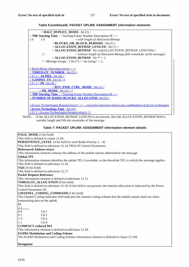
ETSI
Error! No text of specified style in document.157Error! No text of specified style indocument.
Table 6 (continued): PACKET UPLINK ASSIGNMENT information elements
< HALF_DUPLEX_ MODE : bit (1) >< TBF Starting Time : < Starting Frame Number Description IE > >{ 0 { 0 -- with length of Allocation Bitmap
< BLOCKS_OR_BLOCK_PERIODS : bit (1) >< ALLOCATION_BITMAP_LENGTH : bit (7) >< ALLOCATION_BITMAP : bit (val(ALLOCATION_BITMAP_LENGTH)) >
| 1 -- without length of Allocation Bitmap (fills remainder of the message)< ALLOCATION_BITMAP : bit ** > }
! < Message escape : 1 bit (*) = <no string> > } ;
< Multi Block Allocation struct > ::= < TIMESLOT_NUMBER : bit (3) > { 0 | 1 < ALPHA : bit (4) > < GAMMA_TN : bit (5) >} { 0 | 1 < P0 : bit (4) > < BTS_PWR_CTRL_MODE : bit (1) > < PR_MODE : bit (1) > } < TBF Starting Time : < Starting Frame Number Description IE > > < NUMBER OF RADIO BLOCKS ALLOCATED: bit (2)>;
<Access Technologies Request struct> ::= -- recursive structure allows any combination of Access technogies <Access Technology Type : bit (4)> { 0 | 1 <Access Technologies Request struct> };
NOTE: If the ALLOCATION_BITMAP_LENGTH is not present, then the ALLOCATION_BITMAP field isvariable length and fills the remainder of the message.
Table 7: PACKET UPLINK ASSIGNMENT information element details
PAGE_MODE (2 bit field)This field is defined in clause 12.20.PERSISTENCE_LEVEL (4 bit field for each Radio Priority 1…4)This field is defined in subclause 12.14, PRACH Control Parameters.Referenced Address structThis information element contains the address of the mobile station addressed by the message.Global TFIThis information element identifies the uplink TFI, if available, or the downlink TFI, to which this message applies.This field is defined in subclause 12.10.TQI (16 bit field)This field is defined in subclause 12.17.Packet Request ReferenceThis information element is defined in subclause 12.11.TIMESLOT_ALLOCATION (8 bit field)This field is defined in subclause 12.18. If this field is not present, the timeslot allocation is indicated by the PowerControl Parameters IE.CHANNEL_CODING_COMMAND (2 bit field)The Channel Coding Indicator field indicates the channel coding scheme that the mobile station shall use whentransmitting data on the uplink.bit2 1 0 0 CS-10 1 CS-21 0 CS-31 1 CS-4COMPACT reduced MAThis information element is defined in subclause 12.29.EGPRS Modulation and Coding SchemeThe EGPRS Modulation and Coding Scheme information element is defined in clause 12.10d.
Resegment

ETSI
Error! No text of specified style in document.158Error! No text of specified style indocument.
The Resegment information element is defined in clause 12.10e.
EGPRS Window SizeThis information element is defined in subclause 12.5.2.

ETSI
Error! No text of specified style in document.159Error! No text of specified style indocument.
Table 7 (continued): PACKET UPLINK ASSIGNMENT information element details
TLLI_BLOCK_CHANNEL_CODING (1 bit field)This field indicates the channel coding command that the mobile station shall use for any RLC data block containing aTLLI field in the RLC data block header. This field is coded as shown:0 the MS shall use CS-1 in GPRS TBF mode or MCS-1 in EGPRS TBF mode for any RLC data blockcontaining a TLLI in the RLC data block header1 the MS shall use the value commanded in the CHANNEL_CODING_COMMAND for any RLC data block
containing a TLLI in the RLC data block headerBEP_PERIOD2 (4 bit field)This field contains a constant which is used for filtering channel quality measurements in EGPRS. BEP_PERIOD2when present shall be used instead of BEP_PERIOD. For details see GSM 05.08.Range: 0 to 15UPLINK_TFI_ASSIGNMENT (5 bit field)This information element, if present, assigns the contained TFI to the mobile station to identify to uplink TBF describedby this message. This field is coded the same as the TFI field defined in subclause 12.15.Packet Timing AdvanceThis information element is defined in subclause 12.12.Frequency ParametersThis information element, if present, assigns frequency parameters to the uplink TBF. If this information element is notpresent the mobile station shall use its previously assigned frequency parameters. This information element is defined insubclause 12.8.Dynamic Allocation structThis information element contains parameters necessary to define the radio resources of a dynamic allocation or anextended dynamic allocation.Extended Dynamic Allocation (1 bit field)This information field indicates the medium access mode to be used during the TBF.0 Dynamic Allocation1 Extended Dynamic AllocationPower Control ParametersThis information element, if present, contains power control parameters and the timeslot allocation for the mobilestation. If this information element is not present, the MS shall continue to use the previous parameters. Thisinformation element is defined in subclause 12.13.RLC_DATA_BLOCKS_GRANTED (8 bit field)The RLC/MAC blocks Granted field assigns a fixed number of RLC data blocks that the mobile station shall transmitduring the uplink TBF. If the RLC_DATA_BLOCKS_GRANTED field is present the mobile station shall transmit onlythe assigned number of RLC data blocks. Otherwise the duration of the uplink TBF is undefined. Retransmissions ofnegatively acknowledged RLC data blocks do not apply toward the maximum number. This field is encoded as a binarynumber as shown: bit8 7 6 5 4 3 2 10 0 0 0 0 0 0 0 9 RLC data blocks0 0 0 0 0 0 0 1 10 RLC data blocks . . . 1 1 1 1 1 1 1 1 264 RLC data blocksTBF Starting TimeThe TBF Starting Time field contains a starting time that indicates the framenumber during which the assigned TBFmay start.
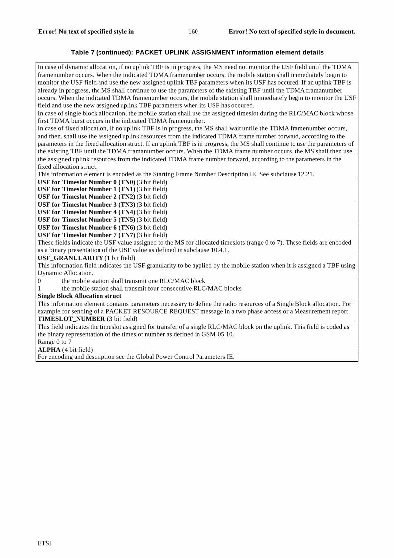
ETSI
Error! No text of specified style in document.160Error! No text of specified style indocument.
Table 7 (continued): PACKET UPLINK ASSIGNMENT information element details
In case of dynamic allocation, if no uplink TBF is in progress, the MS need not monitor the USF field until the TDMAframenumber occurs. When the indicated TDMA framenumber occurs, the mobile station shall immediately begin tomonitor the USF field and use the new assigned uplink TBF parameters when its USF has occured. If an uplink TBF isalready in progress, the MS shall continue to use the parameters of the existing TBF until the TDMA framanumberoccurs. When the indicated TDMA framenumber occurs, the mobile station shall immediately begin to monitor the USFfield and use the new assigned uplink TBF parameters when its USF has occured.In case of single block allocation, the mobile station shall use the assigned timeslot during the RLC/MAC block whosefirst TDMA burst occurs in the indicated TDMA framenumber.In case of fixed allocation, if no uplink TBF is in progress, the MS shall wait untile the TDMA framenumber occurs,and then. shall use the assigned uplink resources from the indicated TDMA frame number forward, according to theparameters in the fixed allocation struct. If an uplink TBF is in progress, the MS shall continue to use the parameters ofthe existing TBF until the TDMA framanumber occurs. When the TDMA frame number occurs, the MS shall then usethe assigned uplink resources from the indicated TDMA frame number forward, according to the parameters in thefixed allocation struct.This information element is encoded as the Starting Frame Number Description IE. See subclause 12.21.USF for Timeslot Number 0 (TN0) (3 bit field)USF for Timeslot Number 1 (TN1) (3 bit field)USF for Timeslot Number 2 (TN2) (3 bit field)USF for Timeslot Number 3 (TN3) (3 bit field)USF for Timeslot Number 4 (TN4) (3 bit field)USF for Timeslot Number 5 (TN5) (3 bit field)USF for Timeslot Number 6 (TN6) (3 bit field)USF for Timeslot Number 7 (TN7) (3 bit field)These fields indicate the USF value assigned to the MS for allocated timeslots (range 0 to 7). These fields are encodedas a binary presentation of the USF value as defined in subclause 10.4.1.USF_GRANULARITY (1 bit field)This information field indicates the USF granularity to be applied by the mobile station when it is assigned a TBF usingDynamic Allocation.0 the mobile station shall transmit one RLC/MAC block1 the mobile station shall transmit four consecutive RLC/MAC blocksSingle Block Allocation structThis information element contains parameters necessary to define the radio resources of a Single Block allocation. Forexample for sending of a PACKET RESOURCE REQUEST message in a two phase access or a Measurement report.TIMESLOT_NUMBER (3 bit field)This field indicates the timeslot assigned for transfer of a single RLC/MAC block on the uplink. This field is coded asthe binary representation of the timeslot number as defined in GSM 05.10.Range 0 to 7ALPHA (4 bit field)For encoding and description see the Global Power Control Parameters IE.
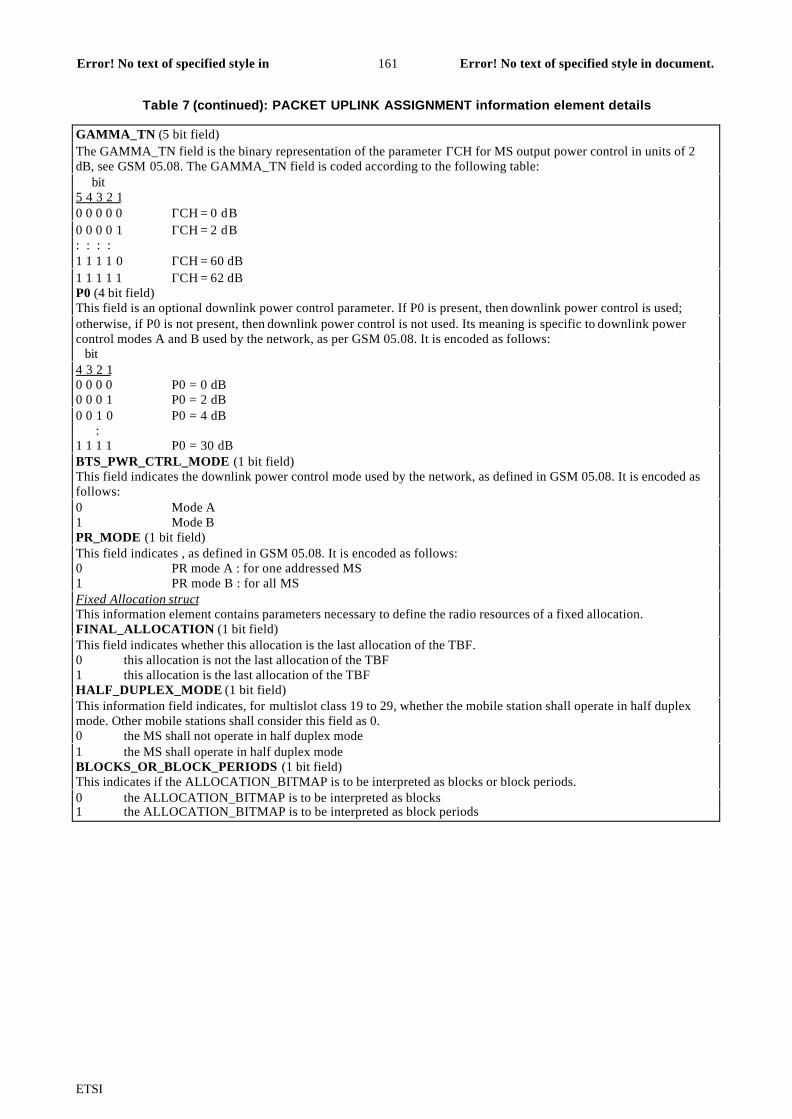
ETSI
Error! No text of specified style in document.161Error! No text of specified style indocument.
Table 7 (continued): PACKET UPLINK ASSIGNMENT information element details
GAMMA_TN (5 bit field)The GAMMA_TN field is the binary representation of the parameter ΓCH for MS output power control in units of 2dB, see GSM 05.08. The GAMMA_TN field is coded according to the following table: bit5 4 3 2 10 0 0 0 0 ΓCH = 0 dB0 0 0 0 1 ΓCH = 2 dB: : : :1 1 1 1 0 ΓCH = 60 dB1 1 1 1 1 ΓCH = 62 dBP0 (4 bit field)This field is an optional downlink power control parameter. If P0 is present, then downlink power control is used;otherwise, if P0 is not present, then downlink power control is not used. Its meaning is specific to downlink powercontrol modes A and B used by the network, as per GSM 05.08. It is encoded as follows: bit4 3 2 10 0 0 0 P0 = 0 dB0 0 0 1 P0 = 2 dB0 0 1 0 P0 = 4 dB :1 1 1 1 P0 = 30 dBBTS_PWR_CTRL_MODE (1 bit field)This field indicates the downlink power control mode used by the network, as defined in GSM 05.08. It is encoded asfollows:0 Mode A1 Mode BPR_MODE (1 bit field)This field indicates , as defined in GSM 05.08. It is encoded as follows:0 PR mode A : for one addressed MS1 PR mode B : for all MSFixed Allocation structThis information element contains parameters necessary to define the radio resources of a fixed allocation.FINAL_ALLOCATION (1 bit field)This field indicates whether this allocation is the last allocation of the TBF.0 this allocation is not the last allocation of the TBF1 this allocation is the last allocation of the TBFHALF_DUPLEX_MODE (1 bit field)This information field indicates, for multislot class 19 to 29, whether the mobile station shall operate in half duplexmode. Other mobile stations shall consider this field as 0.0 the MS shall not operate in half duplex mode1 the MS shall operate in half duplex modeBLOCKS_OR_BLOCK_PERIODS (1 bit field)This indicates if the ALLOCATION_BITMAP is to be interpreted as blocks or block periods.0 the ALLOCATION_BITMAP is to be interpreted as blocks1 the ALLOCATION_BITMAP is to be interpreted as block periods
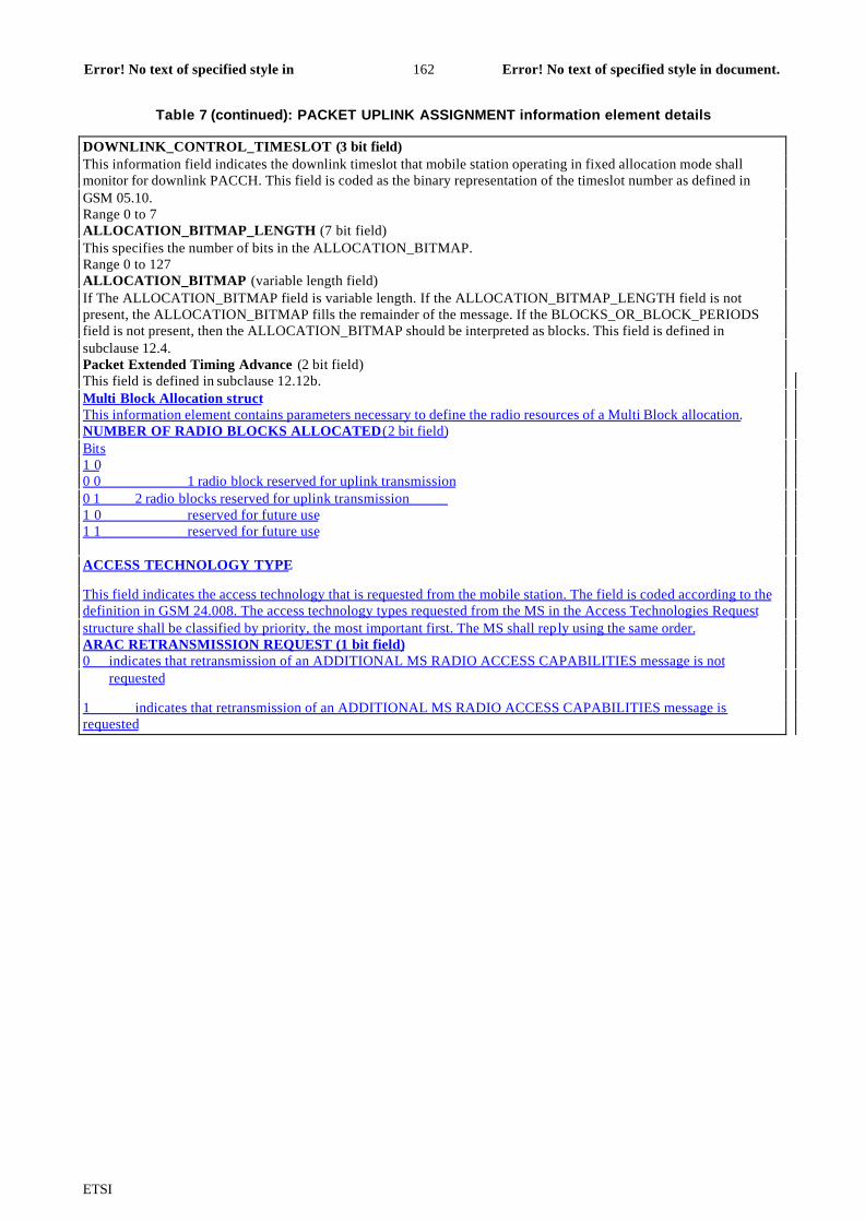
ETSI
Error! No text of specified style in document.162Error! No text of specified style indocument.
Table 7 (continued): PACKET UPLINK ASSIGNMENT information element details
DOWNLINK_CONTROL_TIMESLOT (3 bit field)This information field indicates the downlink timeslot that mobile station operating in fixed allocation mode shallmonitor for downlink PACCH. This field is coded as the binary representation of the timeslot number as defined inGSM 05.10.Range 0 to 7ALLOCATION_BITMAP_LENGTH (7 bit field)This specifies the number of bits in the ALLOCATION_BITMAP.Range 0 to 127ALLOCATION_BITMAP (variable length field)If The ALLOCATION_BITMAP field is variable length. If the ALLOCATION_BITMAP_LENGTH field is notpresent, the ALLOCATION_BITMAP fills the remainder of the message. If the BLOCKS_OR_BLOCK_PERIODSfield is not present, then the ALLOCATION_BITMAP should be interpreted as blocks. This field is defined insubclause 12.4.Packet Extended Timing Advance (2 bit field)This field is defined in subclause 12.12b.Multi Block Allocation structThis information element contains parameters necessary to define the radio resources of a Multi Block allocation.NUMBER OF RADIO BLOCKS ALLOCATED(2 bit field)Bits1 00 0 1 radio block reserved for uplink transmission0 1 2 radio blocks reserved for uplink transmission 1 0 reserved for future use1 1 reserved for future use
ACCESS TECHNOLOGY TYPE
This field indicates the access technology that is requested from the mobile station. The field is coded according to thedefinition in GSM 24.008. The access technology types requested from the MS in the Access Technologies Requeststructure shall be classified by priority, the most important first. The MS shall reply using the same order.ARAC RETRANSMISSION REQUEST (1 bit field)0 indicates that retransmission of an ADDITIONAL MS RADIO ACCESS CAPABILITIES message is not
requested
1 indicates that retransmission of an ADDITIONAL MS RADIO ACCESS CAPABILITIES message isrequested

ETSI
Error! No text of specified style in document.163Error! No text of specified style indocument.
11.2.32 Additional MS Radio AccessCapabilitiesThis message is sent on the PACCH by the mobile station to the network to inform about radio access capabilities of themobile station.
Message type:Additional MS Radio Access Capabilities
Direction: mobile station to network
Table X: ADDITIONAL MS RADIO ACCESS CAPABILITIES information elements
< Additional MS Radio Access Capabilities message content > ::= { 0 | 1 < ACCESS_TYPE : bit (2) > } { 0 < Global TFI : < Global TFI IE > > | 1 < TLLI : < TLLI IE > > } < MS Radio Access Capability : < MS Radio Access Capability IE > > < spare padding > ;
Table 8: ADDITIONAL MS RADIO ACCESS CAPABILITIES information element details
Global TFIThis information element contains the TFI of the mobile station's uplink TBF, if available, or the TFI of the mobilestation's downlink TBF. If no TFI is available, this field is omitted. This field is defined in clause 12.10.ACCESS_TYPE (2 bit field)This field indicates the reason for requesting the access. It shall be included only in response to a Multi blockassignment.bit2 10 0 Two Phase Access Request0 1 Page Response1 0 Cell Update1 1 Mobility Management procedureTLLI IE (32 bit field)This information element is defined in Clause 12.16.MS Radio Access CapabilityThis information element is sent during one phase and two phase access procedures. This information element is codedas defined by the MS RA capability value part defined in the MS Radio Access Capability IE defined in GSM 24.008.This information element is coded as defined in GSM 24.008, but with all padding bits omitted. An EGPRS capablemobile station shall always provide its EGPRS capability in the MS Radio Access Capability.
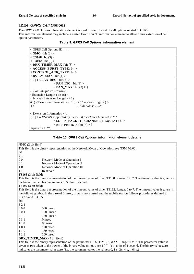
ETSI
Error! No text of specified style in document.164Error! No text of specified style indocument.
12.24 GPRS Cell OptionsThe GPRS Cell Options information element is used to control a set of cell options related to GPRS.This information element may include a nested Extension Bit information element to allow future extension of celloption parameters.
Table 9: GPRS Cell Options information element
< GPRS Cell Options IE > ::=< NMO : bit (2) >< T3168 : bit (3) >< T3192 : bit (3) >< DRX_TIMER_MAX : bit (3) >< ACCESS_BURST_TYPE : bit >< CONTROL_ACK_TYPE : bit >< BS_CV_MAX : bit (4) >{ 0 | 1 < PAN_DEC : bit (3) >
< PAN_INC : bit (3) >< PAN_MAX : bit (3) > }
-- Possible future extension:<Extension Length : bit (6)>< bit (val(Extension Length) + 1)& { <Extension Information > ! { bit ** = <no string> } } > } ; -- sub-clause 12.26
< Extension Information> : : ={ 0 | 1 -- EGPRS supported by the cell if the choice bit is set to ‘1’
<EGPRS_PACKET_ CHANNEL_REQUEST : bit>< BEP_PERIOD : bit (4) > }
<spare bit > ** ;
Table 10: GPRS Cell Options information element details
NMO (2 bit field)This field is the binary representation of the Network Mode of Operation, see GSM 03.60:bit2 10 0 Network Mode of Operation I0 1 Network Mode of Operation II1 0 Network Mode of Operation III1 1 Reserved.T3168 (3 bit field)This field is the binary representation of the timeout value of timer T3168. Range: 0 to 7. The timeout value is given asthe binary value plus one in units of 500millisecond.T3192 (3 bit field)This field is the binary representation of the timeout value of timer T3192. Range: 0 to 7. The timeout value is given inthe following table. In the case of 0 msec, timer is not started and the mobile station follows procedures defined in9.3.2.5 and 9.3.3.5: bit3 2 10 0 0 500 msec0 0 1 1000 msec0 1 0 1500 msec0 1 1 0 msec1 0 0 80 msec1 0 1 120 msec1 1 0 160 msec1 1 1 200 msecDRX_TIMER_MAX (3 bit field)This field is the binary representation of the parameter DRX_TIMER_MAX. Range: 0 to 7. The parameter value isgiven as two taken to the power of the binary value minus one (2 (bv - 1) ) in units of 1 second. The binary value zeroindicates the parameter value zero (i.e, the parameter takes the values: 0, 1 s, 2 s, 4 s, .. 64 s.)

ETSI
Error! No text of specified style in document.165Error! No text of specified style indocument.
ACCESS_BURST_TYPE (1 bit field)The ACCESS_BURST_TYPE field indicates if 8 or 11 bit access burst shall be used on PRACH, PTCCH/U and in thePACKET CONTROL ACKNOWLEDGMENT message when the format is four access bursts. The field is codedaccording to the following table:0 8 bit access burst s hall be used1 11 bit access burst shall be usedCONTROL_ACK_TYPE (1 bit field)This field is the binary representation of the default format of the PACKET CONTROL ACKNOWLEDGMENTmessage:0 default format is four access bursts1 default format is RLC/MAC control block.BS_CV_MAX (4 bit field)This field is the binary representation of the parameter BS_CV_MAX. Range: 0 to 15. The value BS_CV_MAX=0shall be interpreted as value BS_CV_MAX=1 for calculation of T3198, T3200 and N3104max values.PAN_DEC (3 bit field)This field is the binary representation of the parameter PAN_DEC. Range: 0 to 7.PAN_INC (3 bit field)This field is the binary representation of the parameter PAN_INC. Range: 0 to 7.
Table 10 (continued): GPRS Cell Options information element details
PAN_MAX (3 bit field)This field defines the maximum value allowed for counter N3102. bit3 2 10 0 0 maximum value allowed for counter N3102 is 40 0 1 maximum value allowed for counter N3102 is 8 . . .1 1 1 maximum value allowed for counter N3102 is 32EGPRS_PACKET_CHANNEL_REQUEST (1 bit field)0 EGPRS capable MSs shall use EGPRS PACKET CHANNEL REQUEST _message for uplink TBF
establishment on the PRACH when there is a PBCCH in the cell GPRS Cell Options IE is broadcaston the PSI1 or on the RACH when there is no PBCCH in the cell. GPRS Cell Options IE isbroadcast on the SI13/PSI13.1 EGPRS capable MSs shall use two phase access with PACKET CHANNEL REQUEST message onthe PRACH
not EGPRS PACKET CHANNEL REQUEST message for uplink TBF establishment when there is aPBCCH in the cell GPRS Cell Options IE is broadcast on the PSI 1. EGPRS capable MSs shalluse two phase access with CHANNEL REQUEST message on the RACH when there is no PBCCHin the cell. GPRS Cell Options IE is broadcast on the SI13/PSI13.BEP_PERIOD (4 bit field)This field contains the bit error probability (BEP) filter averaging period, refer to GSM 05.08.

ETSI
13.1 Timers on the Mobile Station side
Table 11: Specification of timers used in GPRS on the Mobile Station side
timer started stopped action at expiry valueT3158 Started when ordered by a
NETWORK_CONTROL_ORDER and then restarted each timea Network Controlled (NC)Measurement is performed inMM Ready state and in packetidle or packet transfer mode
See 05.08 Restart the timer, perform themeasurement and send a NCMeasurement report. The timershall be restarted with either ofthe parametersNC_REPORTING_PERIOD_Iwhen in packet idle mode orwith the parameterNC_REPORTING_PERIOD_Twhen in packet transfer mode
Defined bytheparameteror by arandomvalue (seeGSM05.08)
T3162 On receipt of a PACKETQUEUING NOTIFICATION
On receipt of a PACKETUPLINK ASSIGNMENT
Abort Packet access procedure;indicate Packet access failure toupper layers and Return topacket idle mode listening to itspaging subchannel
5 sec
T3164 On receipt of a PACKETUPLINK ASSIGNMENT
At sending of the first RLC/MACblock
See subclause 7.1.4. 5 sec
T3166 At sending of the first RLC/MACblock at one phase access
On receipt of a PACKETUPLINK ACK/NACK
Immediately stop transmitting onthe assigned TBF; a TBFestablishment failure hasoccurred or the contentionresolution procedures has failed
5 sec
T3168 At sending the PACKETRESOURCE REQUESTmessage or Channel RequestDescription IE in PACKETDOWNLINK ACK/NACK
On receipt of a PACKETUPLINK ASSIGNMENTmessage
Reinitiate the packet accessprocedure or retransmit thePACKET RESOURCEREQUEST or PACKETDOWNLINK ACK/NACK
assignedin systeminformation
T3170 After having made M + 1attempts to send a PACKETCHANNEL REQUEST orEGPRS PACKET CHANNELREQUEST message, or onreceipt of a PACKET ACCESSREJECT message.
On receipt of a PACKETUPLINK ASSIGNMENT orPACKET QUEUINGNOTIFICATION message
Abort Packet access procedure;indicate a packet access failureto upper layer and return topacket idle mode.
Defined byparameters TX_INTand S
T3172 On receipt of a PACKETACCESS REJECT message
On receipt of a PACKETUPLINK ASSIGNMENTmessage
Packet Access in the cell nolonger prohibited
assignedinmessage
Table 11 (continued): Specification of timers used in GPRS on the Mobile Station side
timer Started Stopped action at expiry valueT3174 On receipt of a PACKET CELL
CHANGE ORDER messageOn receipt of a response toCHANNEL REQUEST orPACKET CHANNEL REQUESTin the new cell
Return to old cell and sendPACKET CELL CHANGEFAILURE
5 sec
T3176 Expiry of T3174 After sending of PACKET CELLCHANGE FAILURE message
Stop cell change order failureprocedure.
5 sec
T3178 Started when ordered by aEXT_MEASUREMENT_ORDERand then restarted each time anextended (EXT) Measurement isperformed in packet idle mode
See 05.08 Restart the timer, perform themeasurement and send an EXTMeasurement report. The timershall be restarted with theparameterEXT_REPORTING_PERIOD
Defined bytheparameteror by aRandomvalue (seeGSM05.08)
T3180 When transmitting an RLC/MACblock to the network
When detecting an assignedUSF value on assigned PDCH
Perform Abnormal release withrandom access procedure
5 sec
T3182 After sending the last data block(with CV = 0), or Upon detectinga transmit window stall condition
On receipt of the PACKETUPLINK ACK/NACK message
Abnormal release with randomaccess
5 sec

ETSI
T3184 On receipt of a PACKETUPLINK ACK/NACK message
On receipt of PACKET UPLINKACK/NACK message(T3184 is also restarted)
Abnormal release with randomaccess
5 sec
T3186 When packet access procedureis started Stopped when receiving any
message from the network inresponse to the PACKETCHANNEL REQUEST messageor after M+1 attempts to sendPACKET CHANNEL REQUESTmessages on the PRACHchannel
Abort Packet access procedure;indicate Packet access failure toupper layers and return toPacket Idle mode.
5 sec
T3188 If a new fixed allocation hasbeen requested, when all datahas been sent on the assignedallocation
On receipt of PACKET UPLINKASSIGNMENT, PACKETUPLINK ACK/NACK messagecontaining a fixed allocation, orPACKET ACCESS REJECT
Resend the last allocationrequest if it needs more data tocomplete the TBF
5 sec
T3190 At reception of a downlinkassignment message
Restarted on receipt of data onthe resources
Abnormal release with return toCCCH or PCCCH
5 sec
T3192 At sending the PACKETDOWNLINK ACK/NACK withthe Final Ack Indicator=1, or atsending the PACKETCONTROL ACK as a responseto final RLC data block inunacknowledged mode.
Restarted at sending thePACKET DOWNLINKACK/NACK with the Final AckIndicator=1, or at sending thePACKET CONTROL ACK as aresponse to final RLC data blockin unacknowledged mode.Stopped at the reception of aPACKET DOWNLINKASSIGNMENT or PACKETTIMESLOT RECONFIGURE.
Release the resources, stopmonitoring the PDCHs, andbegin to monitor the pagingchannel
assignedin systeminformation
T3198 When transmitting RLC datablock.When transmitting PACKETRESOURCE REQUEST duringEGPRS One Phase Accessprocedure or ADDITIONAL MSRADIO ACCESSCAPABILITIES message duringeither EGPRS One Phase orTwo Phase Access procedures.
None Accept negativeacknowledgement for RLC datablock.Accept a request forretransmission for PACKETRESOURCE REQUEST orADDITIONAL MS RADIOACCESS CAPABILITIESmessages.
BS_CV_MAX valuewhich isbroadcastin systeminformation. SSeeclause9.1.3.
T3200 On receipt of an RLC/MACcontrol block containing asegment of an RLC/MAC controlmessage
On receipt of an RLC/MACcontrol block containing asegment of an RLC/MAC controlmessage such that the mobilestation now has the completecontrol message
Discard and ignore all segmentsof the partially receivedRLC/MAC control message
see clause9.1.11b
T3204 The first attempt to send aPACKET CHANNEL REQUESTduring a packet accessprocedure. The PACKETCHANNEL REQUEST wasattempted indicating 'Singleblock without TBFestablishment' and the purposeof the packet access procedureis to send a PACKET PAUSEmessage.
Upon receipt of a PACKETUPLINK ASSIGHNMENT.
The packet pause procedure(subclause 7.6) is aborted
1 sec
T3158: Wait for sending measurement reports for network controlled cell reselection.
This timer is used on the mobile station side to define the period for performingNC-measurements and send measurement reports in either packet idle or packettransfer mode (see GSM 05.08).

ETSI
T3162: Wait for Packet Uplink Assignment after reception of Packet QueuingNotification
This timer is used on the mobile station side after received Packet QueuingNotification to define when to stop waiting for a Packet Uplink Assignment.
T3164: Wait for Uplink State Flag After Assignment
This timer is used on the mobile station side to define when to stop waiting for theUSF determining the assigned portion of the uplink channel and repeat theprocedure for random access. In multislot operation, it is enough that the assignedUSF is noted on one of the uplink PDCHs. This timer is not used when fixedallocations are assigned.
T3166: Wait for Packet Uplink ACK/NACK after sending of first data block
This timer is used on the mobile station side to define when to stop waiting for aPacket Uplink ACK/NACK after sending of the first data block.
T3168: Wait for Packet Uplink Assignment message
This timer is used on the mobile station side to define when to stop waiting for aPacket Uplink Assignment message after sending of a Packet Resource requestmessage.
T3170: Wait for Packet Uplink Assignment after having done (M+1) Packet ChannelRequests or after reception of a PACKET ACCESS REJECT message.
This timer is used on the mobile station side when having made M + 1 attempts tosend a Packet Channel Request or after reception of a PACKET ACCESSREJECT message. At expiry of timer T3170, the mobile station shall abort thepacket access procedure,indicate a packet access failure to upper layer and returnto packet idle mode.
The value of this timer is equal to the time taken by T+2S TDMA frames, T and Sare defined in subclause 7.1.2.1.1.
T3172: Prohibit packet access in the cell after Packet Access Reject message has beenreceived.
This timer is used on the mobile station side on receipt of a Packet Access Rejectmessage corresponding to one of the mobile station’s 3 last Packet ChannelRequest messages. If T3172 expires before receiving an assignment message, themobile station returns to packet idle mode.
After T3172 expiry packet Access is no longer prohibited in the cell but noChannel Request message shall be sent as a response to a page until a PagingRequest message for the mobile station is received.
T3174: Wait for response on new cell after Packet Cell Change Order .
This timer is used on the mobile station side on receipt of a PACKET CELLCHANGE ORDER message. The timer is stopped upon successful access on thenew cell. On expiry, the mobile station returns to the old cell and send PACKETCELL CHANGE FAILURE message.
T3176: Stop Cell Change failure procedure .
This timer started when T3174 expires. The timer is stopped upon transmission ofthe PACKET CELL CHANGE FAILURE message. On expiry, the mobile stationstops attempting to send the PACKET CELL CHANGE FAILURE message.

ETSI
T3178: Wait for sending extended measurement reports.
This timer is used on the mobile station side to define the period for performingextended measurements and send extended measurement reports in packet idlemode (see GSM 05.08).
T3180: Wait for Uplink State Flag After Data Block
This timer is used on the mobile station side to define when to stop waiting for theUSF determining the assigned portion of the uplink channel after the perviousRLC/MAC block is sent. In multislot operation, it is enough that the assignedUSF is noted on one of the uplink PDCHs. If expired, the mobile station repeatsthe procedure for random access. This timer does not apply to fixed allocationtransfers.
T3182: Wait for Acknowledgement
This timer is used on the mobile station side to define when to stop waiting fortemporary Packet Uplink Ack/Nack after the last RLC data block has been sentfor the current send window or for the entire Temporary Block Flow.
T3184: No Ack/Nack Received
This timer is used on the mobile station side to decide when to stop waiting for aPacket Uplink Ack/Nack. (This timer does not apply to mobiles performing adynamic allocation transfer).
T3186: Supervision of the random access procedure
This timer is used on the mobile station side to define the maximum allowed timeto repeat the sending of all PACKET CHANNEL REQUEST messages. At expiryof timer T3186, the Packet Uplink establishment procedure is aborted.
T3188: Allocation Exhausted
This timer is used on the mobile station side to decide when to stop waiting toreceive additional resources from the network. (This timer does not apply to amobile performing a dynamic allocation transfer).
T3190: Wait for Valid Downlink Data Received from the Network
This timer is used on the mobile station side to stop waiting for the valid datafrom the network side either following the initial Packet Downlink Assignment orafter some previous downlink RLC/MAC block.
T3192: Wait for release of the TBF after reception of the final block
This timer is used on the mobile station side when the mobile station has receivedall of the RLC data blocks. When timer T3192 expires the mobile station shallrelease the resources associated with the TBF (e.g. TFI) and begin to monitor itspaging channel.
T3198: RLC timer
T3198 is used by the mobile station to control when it will accept a negativeacknowledgement for an RLC data block or a PACKET RESOURCE REQUESTor ADDITIONAL MS RADIO ACCESS CAPABILITIES message. The mobilestation shall set an instance of timer T3198 for each RLC data block transmitted inan RLC window. For GPRS the RLC window size is 64. For EGPRS the RLCwindow size is 64 – 1024.

ETSI
T3200 RLC/MAC control message reassembly guard
T3200 is used by the mobile station to control when it will discard segments of apartially received RLC/MAC control message. The mobile station shall have oneinstance of timer T3200 for each segmented RLC/MAC control message that themobile station is capable of receiving in parallel.
T3204: Wait for Packet Uplink Assignment after the first attempt to send a PacketChannel Request during a packet access procedure. The Packet Channel Requestwas attempted indicating 'Single block without TBF establishment' and thepurpose of the packet access procedure is to send a PACKET PAUSE message.
This timer is used by a mobile station with non-GSM capabilities to stop waitingfor a PACKET UPLINK ASSIGNMENT message. At expiry of timer T3204, thePacket Pause procedure (subclause 7.6) is aborted.

ETSI
3GPP/SMG2 Meeting #35 Document 937/00
Schaumburg, Illinois USA, 3 – 7 April 2000 Agenda Item 7.1.5.10
CHANGE REQUEST
Current Version: 8.3.004.60 CR A841 r1
GSM (AA.BB) or 3G (AA.BBB) specification number ↑ ↑ CR number as allocated by MCC support team
For submission to: for approval strategic (for SMG
list expected approval meeting # here↑
for information non-strategic use only)
Form: CR cover sheet, version 2 for 3GPP and SMG The latest version of this form is available from: ftp://ftp.3gpp.org/Information/CR-Form-v2.doc
Proposed change affects: (U)SIM ME X UTRAN / Radio X Core Network
(at least one should be marked with an X)
Source: Ericsson Date: 2000-04-06
Subject: Corrections of neighbour cell parameters in PSI3bis (R99)
Work item: EDGE Compact and support for EGPRS in ANSI-136 networks
Category: F Correction X Release: Phase 2
A Corresponds to a correction in an earlier release Release 96
(only one category B Addition of feature Release 97
shall be marked C Functional modification of feature Release 98

ETSI
with an X) D Editorial modification Release 99 X
Release 00
Reason forchange:
1. The CELL_BAR_ACCESS_2 parameter is coded incorrectly (‘bit(2)’ instead of‘bit(1)’) in the ‘COMPACT Neighbour Cell params struct’.
2. The label used for the EXC_ACC parameter is incorrect in the ‘COMPACTNeighbour Cell params struct’.
3. The default values for parameters contained in or referenced by the ‘COMPACTNeighbour Cell params struct’ are defined differently to the general rule defined forthe neighbour cell parameters in PSI3-bis.
The proposed solution for the last problem is to align the ‘COMPACT Neighbour Cellparams struct’ to the general rule defined for default values. Additionaly, editorialcorrections are made to the descriptions of both the ‘Neighbour Cell params struct’ andthe ‘COMPACT Neighbour Cell params struct’ in order to align these descriptions andto remove duplications and other redundant text (probably a reminder from an earlierversion of the specification).
Clauses affected: 11.2.21
Other specs Other 3G core specifications → List of CRs:
affected: Other GSM corespecifications
→ List of CRs:
MS test specifications → List of CRs:
BSS test specifications → List of CRs:
O&M specifications → List of CRs:
Othercomments:
11.2.21 Packet SystemInformation Type 3 bisThis message is sent by the network on the PBCCH and PACCH giving information of the BCCHallocation in the neighbour cells and cell selection parameters for non-serving cells. This message shallnot be segmented across more than one RLC/MAC control block by using the procedures specified insubclause 9.1.11a. If not all information fits into one instance of the PSI3bis message, the PSI3bismessage can be repeated. Special requirements for the transmission of this message apply on PBCCH,see GSM 05.02.
Message type:PACKET SYSTEM INFORMATION TYPE 3 BIS
Direction: network to mobile station
Classification:distribution message

ETSI
Table 12: PSI3 bis information elements
< PSI3 bis message content > ::=< PAGE_MODE : bit (2) >< PSI3_CHANGE_MARK : bit (2) >< PSI3_BIS_INDEX : bit (4) >< PSI3_BIS_COUNT : bit (4) >{ < Neighbour cell parameters : { 1 < Neighbour cell params struct > } ** 0 >
< Neighbour Cell parameters 2 : { 1 < Neighbour Cell params 2 struct > } ** 0 >-- may be repeated many times
{ null | 0bit** = < no string >| 1
-- Release 1998 additions:{ 0 | 1 < LSA Parameters : < LSA Parameters IE >> }{ 0 | 1 < COMPACT Neighbour Cell Parameters :
{ 1 < COMPACT Neighbour Cell params struct > } ** 0 >< padding bits > } } // -- truncation at end of message allowed,
bits ‘0’ assumed ! < Distribution part error : bit (*) = < no string > > ;
< Neighbour cell params struct > ::=< START_FREQUENCY : bit (10) >< Cell selection params : < Cell Selection struct > >< NR_OF_REMAINING_CELLS : bit (4) >< FREQ_DIFF_LENGTH : bit (3) >{ < FREQUENCY_DIFF : bit (1 + val(FREQ_DIFF_LENGTH)) >
< Cell selection params : <Cell Selection struct> > } *(val(NR_OF_REMAINING_CELLS)) ;
< Cell Selection struct > ::=< BSIC : bit (6) >< CELL_BAR_ACCESS_2 : bit >< EXC_ACC : bit >< SAME_RA_AS_SERVING_CELL : bit (1) >{ 0 | 1 < GPRS_RXLEV_ACCESS_MIN : bit (6) >
< GPRS_MS_TXPWR_MAX_CCH : bit (5) > }{ 0 | 1 < GPRS_TEMPORARY_OFFSET : bit (3) >
< GPRS_PENALTY_TIME : bit (5) > }{ 0 | 1 < GPRS_RESELECT_OFFSET : bit (5) > }{ 0 | 1 < HCS params : < HCS struct > > }{ 0 | 1 < SI13_PBCCH_LOCATION : < SI13_PBCCH_LOCATION struct > > } ;
< SI13_PBCCH_LOCATION struct > ::={ 0 < SI13_LOCATION : bit (1) >| 1 < PBCCH_ LOCATION : bit (2) >
< PSI1_REPEAT_PERIOD : bit (4) > } ;
< HCS struct > ::=< PRIORITY_CLASS : bit (3) >< HCS_THR : bit (5) > ;

ETSI
Table 12 (continued): PSI3 bis information elements
< Neighbour Cell params 2 struct > ::=< GENERATION : bit (2) >{ 1
{ 1 < START_FREQUENCY : bit (10) > -- multiple STARTFREQ/FREQ DIFF sets
-- may be defined< SAME_RA_AS_SERVING_CELL : bit (1) >< CELL_BAR_ACCESS_2 : bit >< BCC : bit (3) >< NR_OF_REMAINING_CELLS : bit (4) >
-- i fval(NR_OF_REMAINING_CELLS)=0
--then theCELL_PARAMS_POINTER
-- follows immediately< FREQ_DIFF_LENGTH : bit (3) >{ < FREQUENCY_DIFF : bit (1 + val(FREQ_DIFF_LENGTH)) >
< SAME_RA_AS_SERVING_CELL : bit (1) >< CELL_BAR_ACCESS_2 : bit >< BCC : bit (3) > } * (val(NR_OF_REMAINING_CELLS)) } ** 0
< CELL_PARAMS_POINTER : bit (2) > } ** 0 --up to four pointers to theparameter set< Neighbour parameter set : < Neighbour parameter set struct > > *
(1 + max(val(CELL_PARAMS_POINTER))) ;
< Neighbour parameter set struct > ::= -- the first zero indicates that defaultparameter value(s) -- are used.{ 0 | 1 < NCC : bit (3) > }< EXC_ACC : bit >{ 0 | 1 < GPRS_RXLEV_ACCESS_MIN : bit (6) > }{ 0 | 1 < GPRS_MS_TXPWR_MAX_CCH : bit (5) > }{ 0 | 1 < PRIORITY_CLASS : bit (3) > }{ 0 | 1 < HCS_THR : bit (5) >}{ 0 | 1 < SI13_PBCCH_LOCATION : SI13_PBCCH_LOCATION struct > }< GPRS_TEMPORARY_OFFSET : bit (3) >< GPRS_PENALTY_TIME : bit (5) >< GPRS_RESELECT_OFFSET : bit (5) > ;
< COMPACT Neighbour Cell params struct > ::=< GENERATION : bit (2) >{ 1
{ 1 < START_FREQUENCY : bit (10) > -- multiple STARTFREQ/FREQ DIFF sets
-- may be defined< SAME_RA_AS_SERVING_CELL : bit (1) >< CELL_BAR_ACCESS_2 : bit (2) >< BCC : bit (3) >< NR_OF_REMAINING_CELLS : bit (4) >
-- i fval(NR_OF_REMAINING_CELLS)=0
--then theCELL_PARAMS_POINTER
-- follows immediately< FREQ_DIFF_LENGTH : bit (3) >{ < FREQUENCY_DIFF : bit (1 + val(FREQ_DIFF_LENGTH)) >
< SAME_RA_AS_SERVING_CELL : bit (1) >

ETSI
< CELL_BAR_ACCESS_2 : bit (2) >< BCC : bit (3) > } * (val(NR_OF_REMAINING_CELLS)) } ** 0
< CELL_PARAMS_POINTER : bit (2) > } ** 0 --up to four pointers to theparameter set
<COMPACT Neighbour parameter set :<COMPACT Neighbour parameter set struct > > * (1+max(val(CELL_PARAMS_POINTER))) ;

ETSI
Table 12 (continued): PSI3 bis information elements
< COMPACT Neighbour parameter set struct > ::= -- the first zero indicates that parameter value(s) -- in question are the same as in PSI 3{ 0 | 1 < NCC : bit (3) > }< EXC_ ACC : bit >{ 0 | 1 < GPRS_RXLEV_ACCESS_MIN : bit (6) > }{ 0 | 1 < GPRS_MS_TXPWR_MAX_CCH : bit (5) > }{ 0 | 1 < GPRS_PRIORITY_CLASS : bit (3) > }{ 0 | 1 < GPRS_HCS_THR : bit (5) >}< GPRS_TEMPORARY_OFFSET : bit (3) >< GPRS_PENALTY_TIME : bit (5) >< GPRS_RESELECT_OFFSET : bit (5) >{ 0 | 1 < TIME_GROUP : bit (2) > }{ 0 | 1 < GUAR_CONSTANT_PWR_BLKS : bit (2) >} ;
Table 13: PSI3 bis information element details
PAGE_MODE (2 bit field)See description under PSI3.PSI3_CHANGE_MARK (2 bit field)See description under PSI3.PSI3_BIS_INDEX (4 bit field)The PSI3_BIS_INDEX field is used to distinguish individual PSI3 bis messages containing informationabout different neighbour cells. The field can take the binary representation of the values 0 to n, wheren is the index of the last PSI3 bis message. (PSI3 bis count).PSI3_BIS_COUNT (4 bit field)See description under PSI3.General rules for handling neighbour cell parameter default valuesThe first neighbour cell defined in the first PSI3bis instance uses as its default parameter values theparameter values defined for the last neighbour cell in PSI3.The following neighbour cells in PSI3bis use the parameter values of the previous neighbour cell astheir default values.This principle of referring to the previous cell applies independently of the coding used in PSI3bis(Neighbour cell parameters, and Neighbour cell parameters 2 and COMPACT Neighbour CellParameters).This principle also applies when going from PSI3bis instance i over to PSI3bis instance i+1.Neighbour cell params structThe coding of the Neighbour cell parameters is described under PSI3.Neighbour cell params struct 2This coding may be used if the number of neighbour cells is high and many cells share commonparameter values. The structure contains pointers to the list of sets of actual parameters. The coding ofactual parameters that are contained in or referenced by the Neighbour Cell params 2 struct is describedin PSI3.COMPACT Neighbour Cell params structThe coding of the Neighbour cell parameters is the same as the coding of the Neighbour cell paramsstruct 2, except the two additional parameters, TIME_GROUP andGUAR_CONSTANT_PWR_BLKS. The coding of actual parameters that are contained in orreferenced by the COMPACT Neighbour Cell params struct is described in PSI3. LSA Parameters IEThe LSA Parameters IE is described under PSI3 and in subclause 12.28.The following parameters (GENERATION, CELL_PARAMS_POINTER, BCC and NCC) are notdefined in PSI3:GENERATION (2 bit field)Reserved for future extension. The sender shall use 00. The receiver: if received different from 00discard the structure.

ETSI
CELL_PARAMS_POINTER (2 bit field)Pointer to the parameter set valid for a certain cell group (up to four).

ETSI
Table 13 (continued): PSI3 bis information element details
BCC (3 bit field)BTS Colour Code.Neighbour parameter set structNeighbour parameter set struct and COMPACT Neighbour parameter set structThe actual parameter values for the Neighbour Cell params 2 struct and the COMPACT NeighbourCell params struct are given is thisese structures. Default values for absent parameters are definedaccording to the general rule given above, except:NCC : bit (3). Network Colour Code. The default value is given by the serving cell.GPRS_RXLEV_ACCESS_MIN : bit (6).GPRS_MS_TXPWR_MAX_CCH : bit (5).PRIORITY_CLASS : bit (3).HCS_THR : bit (5).COMPACT Neighbour Cell params structThe coding of the Neighbour cell parameters is as the coding of the Neighbour cell params struct 2, butwith two extra parameters, TIME_GROUP and GUAR_CONSTANT_PWR_BLKS.LSA Parameters IEThe LSA Parameters IE is described under PSI3 and in subclause 12.28.
GENERATION (2 bit field)Reserved for future extension. The sender shall use 00. The receiver: if received different from 00discard the structure.CELL_PARAMS_POINTER (2 bit field)Pointer to the parameter set valid for a certain cell group (up to four).BCC (3 bit field)BTS Colour Code.COMPACT Neighbour parameter set structThe actual parameter values are given is this structure. If a parameter is missing, the following defaultsshall apply:NCC : bit (3). Network Colour Code. The default value is given by the serving cell.GPRS_RXLEV_ACCESS_MIN : bit (6). The default value is given by PSI3.GPRS_MS_TXPWR_MAX_CCH : bit (5). The default value is given by PSI3.GPRS_PRIORITY_CLASS : bit (3). The default value is given by PSI3.GPRS_HCS_THR : bit (5). The default value is given by PSI3.TIME_GROUP : bit (2). The default value is given by PSI3.GUAR_CONSTANT_PWR_BLKS : bit (2). The default value is given by PSI3.