crr 100:1996 safe disposal of vented reacting fluids disposal of vented reacting fluids ......
TRANSCRIPT

3s HSE
Health G Safety Executive
HSE CONTRACT RESEARCH REPORT No. 10011 996
SAFE DISPOSAL OF VENTED REACTING FLUIDS
Dr J Singh
Hazard Evaluation Laboratory Inc. 50 Moxon Street
Barnet Hertfordshire
EN5 5TS
3E HSE
Health 6 Safety Executive
HSE CONTRACT' RESEARCH REPORT No. lOO/l996
SAFE DISPOSAL OF VENTED REACTING FLUIDS
Dr J Singh
Hazard Evaluation Laboratory Inc. 50 Moxon Street
Barnet Hertfordshire
EN5 5TS
Batch reactor vessels used in many sectors of the chemical industry are frequently protected by a relief valve or rupture disc, which will open in case of overpressure, following for example the loss of coolant. It has been found that in many cases, relief actuation is accompanied by the release of a two-phase mixture of gaslvapour and liquid out of the reactor vessel. The release of large amounts of toxic andlor flammable liquid into the atmosphere poses a serious safety and environmental hazard and as a result companies are under pressure to contain the released chemicals.
This report presents the results of a brief study to evaluate the design of disposal equipment downstream of reactor vents, following two-phase relief of an exothermically reacting liquid. The report presents the procedure that must normally be adopted in selecting a disposal unit, the basic equations governing the design and the methodology for experimentally obtaining the data needed.
Four different exothermic chemical reactions are presented as examples, illustrating fully the procedures involved
This report and the work it describes were jointly funded by the Health and Safety Executive and Hazard Evaluation Laboratory Ltd. Its contents, including any opinions and/or conclusions expressed, are those of the author alone and do not necessarily reflect HSE policy.
0 Crown copyright 1996 Applications for reproduction should be made to HMSO First published 1996
lSBNO717611078
All fights reserved No part of this publication may be reproduced, sforedm a refnevaisystem, or transmitted in any form or by any means (electronic, mechanical, photocopying, recordrog, or olhenvrse) without the poor wrinen permission of the copyrighr owner

6.3 EXPERIMENTAL DETAILS 6 . 4 TEST RESULTS 6 . 5 RELIEF SYSTEM DESIGN BASIS 6 . 6 DISPOSAL SYSTEM: SIMPLE KNOCK-OUT DRUM 6 . 7 DISPOSAL SYSTEM: PASSIVE QUENCH 6.8 CONCLUSIONS 6 . 9 REFERENCES
7 . EXAMPLE 2: METHANOL-ACETIC ANHYDRIDE
EXPERIMENTAL DETAILS RESULTS DISPOSAL SYSTEM DESIGN BASIS DISPOSAL INTO ATMOSPHERIC KNOCK-OUT DRUM DESIGN OF PASSIVE QUENCH DRUM SELECTION OF QUENCH DRUM DESIGN CONCLUSIONS REFERENCES
8 . EXAMPLE 3: NITRATION OF TOLUENE
INTRODUCTION OVERVIEW OF MONONITRATION OF TOLUENE EXPERIMENTAL DETAILS TEST RESULTS DISPOSAL SYSTEM DESIGN BASIS DISPOSAL INTO ATMOSPHERIC KNOCK-OUT DRUM DISPOSAL SYSTEM: PASSIVE QUENCH CONCLUSIONS REFERENCES
9 . EXAMPLE 4: H,O, DECOMPOSITION ~.
9 . 1 INTRODUCTION 9 . 2 EXPERIMENTAL DETAILS 9 . 3 TEST RESULT 9 .4 RELIEF SYSTEM DESIGN BASIS 9 . 5 DESIGN OF OPEN KNOCK-OUT DISPOSAL DRUM 9 . 6 DESIGN OF ATMOSPHERIC PRESSURE QUENCH DRUM 9 . 7 CONCLUSIONS
1 0 . CONCLUSIONS
1
1. INTRODUCTION
1.1 NATURE OF PROBLEM
The chemical industry uses large quantities of chemicals which may be toxic and/or flammable in various process units (reactors, storage tanks, intermediate drums etc) . If these units become overpressurized for some reason, the common approach is relieve the pressure through a *weaknessf built into the vessel, usually a bursting disc or valve. If the relief device is large enough, the process unit is protected by preventing overpressurization.
The sizing of a suitable relief device becomes rather complex when the problem is caused by a runaway reaction. The rate of pressure and temperature rise is often difficult to obtain and relief actuation frequently leads to venting of a two-phase mixture of vapour (or gas) and liquid.
The subject of relief for runaway reactions was studied by DIERS (Design Institute for Emergency Relief systemsj in the USA, a project completed in 1984 involving co-operation from many organizations worldwide and costing in the region of $2million for contractor fees alone (Fisher, 1985). As a consequence of the DIERS work, relief sizing for runaway reactions is now quite well understood and safe designs can be completed economically for many types of.reactions, although scope for further research remains.
. ,
An important conclusion of the DIERS project was the fact that it is necessary to carry out experimental testing in order to obtain the data necessary for relief sizing. Indeed the basis for a suitable calorimeter was developed as part of the project and commercial devices have followed on from this.
The objective of relieving a process unit is simply to prevent damage due to overpressurization. The disposal of the vented fluids is a separate matter and was not studied in the DIERS project. In view of the toxicity and/or flammability of most chemicals handled, safe disposal is of course very important and it is no longer. acceptable to vent directly to the atmosphere without due regard for the environment.
OBJECTIVES OF REPORT
The present report is concerned with safe disposal of chemicals following emergency relief of runaway reactions, in effect the next step from the DIERS work.
It is therefore assumed that readers are familiar with the nature of runaway reactions and the associated hazards, as well as a basic understanding of relief sizing for these incidents particularly two-phase behaviour under relief conditions. In order to put the report in proper perspective, an overview of these topics is presented and relevant references provided.
The aim of the report is to allow engineers to develop a process specification suitable for subsequent detailed engineering. The emphasis will be on ensuring that the vented reactants are properly contained, and that the hazard is not simplytransferred from one section of the plant to another. An understanding of the reaction, after relief, is clearly essential if this is to be achieved and therefore the emphasis will be on the use of bench-scale equipment and data analysis and its application to design. This is very similar to the procedures used for relief sizing, following the DIERS project, and indeed similar types Of equipment with some extensions will be used to derive the information.
It is important also to be aware of the sort of information that will not be provided in this report. While types of hardware suitable for containment are mentioned, details of specific types of equipment are not provided. The information necessary to complete a detailed mechanical design will not be provided, only the basis for such a design.
The report is not intended to be a design guide but rather it is an .overview of the problem and some research into how disposal system design may beapproached.
The report will focus on design implications of venting into disposal tanks, either with a view to complete containment or followed by relief into a downstream unit (flare, absorber, incinerator etc) . The use of small scale testing to provide the necessary information and the application of the information will be illustrated with examples.
The chemical systems considered in the report are limited to low viscosity liquids. When the viscosity becomes high (say above 100 cp) the flow through a relief pipe can become laminar, invalidating many of the equations presented. Research into high viscosity systems is currently active.

1.3 RELIEF OF RUNAWAY REACTIONS - OVERVIEW 1.3.1 Relief Sizinq for non-reactinq chemicals (Perrv.1992L
Chemical reactors, storage tanks and most other process vessels are normally fitted with a bursting disc or a relief valve which in the event of accidental overpressurization opens to prevent equipment damage. The size (i.e. effective orifice diameter) of the relief device has to be selected so that it can vent at a sufficiently high rate to compensate for the rate of pressurization. Sizing involves two broad steps:
* determination of the rate of pressure rise * calculation of the vent diameter large enough to cope with
the rise.
Almost invariably, the pressure rise in process equipment is due to the generation of vapour (or gas). The safe relief sizing criterion is therefore:
rate of vapour (or gas) removal 2 rate of vapour (or gas) generation
For example, if fluid in a vented vessel undergoes exothermic reaction producing heat at a rate Q (W) then at steady state the rate of vapour generation M (kg/s) is given by:
I .
where X (J/kg) is the latent heat of vaporization.
Limitations of General A~uroach to Ventinq
When the above approach is applied to reactive systems, a number of assumptions often breakdown. The relief sizing criteria as expressed by equation (1.1) remains valid at all times but equation (1.2) may not represent the total amount of vapour/gas being generated.
If the reaction involves production of volatile gas for example, the rate is not directly related to the heat of reaction and latent heat. Thus, the gas rate needs to be determined in a different manner.
In sizing a vent the rate of vapour (or gas) generation (due to chemical reaction, for example) is normally determined at 'the conditions when the vent opens (or quite close to it). This rate is then used as the basis for vent sizing. Implicit in this is the assumption that cooling by latent heat after the vent opens will prevent any further temperature rise (and hence prevent increase in the rate of pressure rise). This is sometimes valid for reactive system venting but not always.

One obvious case where it is not true is if the reaction generates a large quantity of non-condensible gas; venting the gas will produce no cooling. Thus, the temperature will continue to rise, at the same time increasing the reaction rate. The gas rate for which the vent must be sized will obviously be higher than when the relief device first opened.
The final assumption which is frequently invalid for reactive systems is that the relief device can be sized to vent pure vapour (or gas). I n most cases a two-phase, vapour-liquid froth may have to be vented.
The venting of the entrained liquid (in addition to the vapour) produces relatively little reduction in pressure but its presence in the vent line reduces the vapour (or gas) flow. Thus, the relief device sized for pure vapour will be too small for a two-phase mixture; an order of magnitude underestimation in the area is possible.
1.3.3 Classification of Runawav Reactions for Ventinq
In order to correctly size relief for a runaway reaction, it is necessary first to classify the system according to the types of reaction products and their ability to remove heat during venting. Once this has been done, it is possible to select an appropriate vent sizing equation (Singh, 1990). The same considerations are also very useful in the design of disposal systems.
Vavour Pressure Systems
Vapour systems are those where the system pressure is equal to the vapour pressure of the liquid. In such cases, the reactant will be cooled (due to the latent heat) as vapour is vented; at a sufficiently high vent rate the heat of reaction can be balanced by the cooling effect, resulting in 'tempering' Of the reaction where little or no further temperature rise occurs. Since the pressure and temperature are directly related, the pressure will also cease to rise at this point.
Gassy System
Gassy systems are those where the system pressure is due entirely to the presence of non-condensible gas, rather than the vapour pressure of the liquid. The gas is normally the product Of decomposition. In these mixtures, venting of the gas produces no noticeable cooling because the gas has no latent heat. As a result, the reaction temperature continues to rise during venting; pressure can only be arrested by ensuring that the gas is vented at a sufficiently high rate. Thus, unlike ,yapour systems, the pressure is controlled (and reduced) without cooling the reaction.
In these systems the rate of reaction governing the vent size will clearly be much higher than when the vent first opens.

Hvbrid and Complex Reactions
There are many reactions which do not conform to the simple classifications above and therefore need to be considered differently. One common deviation is systems that have a significant vapour pressure and at the same time produce non-condensible gases - often referred to as hybrids. The behaviour of such reactions during venting depends on the relative contributions to pressure of the vapour and non-condensible gas.
Another complication that can arise is that the nature of the chemical system can change during the course of venting. Consider for example a high boiling reactant dissolved in a relatively volatile solvent. The pressure of the mixture will be determined by the vapour pressure of the solvent and when the system starts to vent it will behave like a tempered system. As the venting proceeds the volatile solvent will be preferentially stripped out leaving the high boiling reactant behind.
When the solvent is finally removed, the temperature will start to increase rapidly to the boiling point of the reactant. At the same time of course, the reaction rate will also increase due both to the increase in temperature and the change in composition.
This is one example of the complications that can arise; deviations can also result from changes in reaction kinetics and stoichiometry during the course of a venting incident. The classification of a reacting system can be influenced by a large number of variables and it is necessary to carry out an experimental assessment in each case to establish the true situation.
1.3.4 Liauid Carrv-Over Durinq Ventinq
In general, the fluid entering the relief device can be considered in one of three categories (see also Section 3.7):
all vapour (or gas), where total disengagement between the vapour (or gas) and liquid occurs
homogeneous two-phase mixture where the vapour (or gas) and liquid are intimately mixed in the vessel so that the phase ratio entering the vent is equal to that within the vessel (zero disengagement)
two-phase vapour-liquid mixture in which the quantity of liquid entrained into the vent is less than that for homogeneous mixing, due to partial disengagement. Two disengagement models are usually considered, bubbly and - churn-turbulent. The terms 'bubbly' and 'churn-turbulent' are used to distinguish the different degrees of liquid swell that takes place due to vapour generation. The former regime relates to slightly less liquid disengagement (i.e. more entrainment) than the latter.
Note that the two-phase or all vapour behaviour of a specific chemical mixture can only be verified through testing or plant experience. Theoretical prediction is not possible. The. occurrence of vapour venting is relatively infrequent in reactive mixtures. In most cases vapour venting will lead to the smallest vent diameter.
Homogeneous venting is approached in many practical cases and is frequently promoted by the inherent "foaminess" of chemical systems which tends to mask the discrete bubble rise behaviour within a vessel. This foam can be produced by very low concentrations (ppm level) of surface-active agents and is quite stable under venting conditions. At present, the onset of this type of flow cannot be predicted from physical properties of the fluid.
When foaming chemicals are vented, the superficial vapour velocity through the vessel has virtually no influence on the vapour-liquid ratio - even quite low velocities will produce two-phase venting. (Superficial vapour velocity is the vapour flow divided by the cross-sectional area of the vessel Fisher, 1991). ~hese aspects are explained in more detail in Section 3.7.
Foamy chemicals are incomplete contrast to other substances where the vapour velocity is crucial in determining whether two-phase or all-vapour venting will occur. The behaviour of these non-foamy fluids is amenable totheoretical description according to whether the fluid exhibits bubbly or churn-turbulent behaviour.
Knowledge of the two-phase regime and the influence of superficialvapour velocity has important practical implications. In the case of a churn-turbulent system for example, it may be deduced that up to 40% of the vessel contents (mostly in the form of liquid) will be vented before vapour venting begins. This has important downstream environmental consequences.
1.3.5 Data Reauired for vent Sizing
The specific data needed to size vents depends on the reaction type:. vapour pressure, gassy or hybrid. (Duxbury and Wilday, 1989, Singh 1990, Perry 1992).
In the case of vapour pressure systems (Leung, 1986), the main variables are:
self-heat rate at the venting point
vapour pressure-temperature relationship
. . liquid. specific heat
Vents for gassy systems (Leung, and Fauske 1987) on the other hand are sized primarily on the basis of the gas generation rate.
The maximum rate is determined experimentally and the vent sized large enough to accommodate the flow.
Hybrid systems (Leung and Fauske 1987) generally require both gas generation rate and the self-heat rate. The vent sizing equation for these reactions depends on the relative quantities of gas and vapour produced.
For example if the pressure rise is due primarily to non-condensible gas then the gassy system equation is used.
In addition to the above data regarding the react'ion, the vent size is also influenced by the nature of the fluid vented - that is the vapour/liquid ratio. The most conservative assumption (i.e. leads to the largest vent) is frequently that of homogeneous two-phase flow of vapour (or gas) and liquid.
Some chemical reactions are too complex to be handled by simple analytical equations. Here, optimal designs can best be obtained by detailed computer modelling.
1.4. ALTERNATIVES TO ATMOSPHERIC VENTING
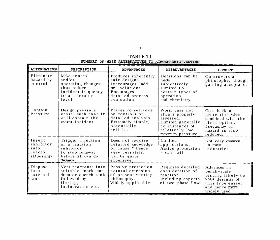
The main considerations in determining the choice of safety system between venting to atmosphere, venting into an external vessel and possibly not venting at all, are safety and cost. The traditional method, venting directly to atmosphere, poses an environmental hazard and possibly a toxic and/or explosion risk to on-site workers and the neighbouring community. However, this method is simple, generally reliable and frequently inexpensive.
main alternatives to this approach are:
elimination of the need for venting by making process control or other operating changes which prevent the incident from occurring
elimination of the need for venting by containing the worst incident within the reactor
elimination of venting by. injection of an inhibitor or quench fluid into the vessel after runaway reaction is detected
disposal of the reactants to another vessel containing a quench fluid or providing a similar facility that avoids release of chemicals to the atmosphere. -. :- . .
above options are not possible for every system and in each case they present different advantages and disadvantages. The first option, essentially avoidance by design, is frequently the most favoured but not always possible in practice.
The effort required to establish the acceptability of this option is quite large.
Containment of the worst credible incident by designing for the maximum pressure, option (b), is only possible in limited cases. Frequently, runaway reactions can lead to extremely high pressures (over 50 bar say) and therefore containment may be very expensive. One attractive consideration is to combine (a) and (b), that is, use better control and operating procedures to 'dilute' the worst credible case and thereby make containment more viable.
Active addition of a fluid that prevents propagation of an incident, option (c) , can be extremely effective if properly designed. Acceptance of this option depends firstly on whether a suitable inhibitor can be located and secondly whether a sufficiently reliable system can be designed.
The final option, venting into an external disposal tank is the reverse of the previous system. The crucial difference is that the protective system is largely passive and so much less likely -to fail, provided of course that it is properly designed and maintained.
The disadvantage is that the hardware may be more elaborate and possibly more expensive.
The present report is concerned with the last option, disposal into external equipment.
The above alternatives and the most important features of each are summarized in table 1.1.
9
TABLE 1.1
ALTERNATIVE
El imina te hazard by c o n t r o l
Contain P re s su re
I n j e c t i n h i b i t o r i n t o r e a c t o r (Dousing)
Dispose i n t o e x t e r n a l t ank
SUMMARY OF MAIN ALTERNATIVES TO i -- I
DESCRIPTION
Make c o n t r o l and/or ope ra t ing changes t h a t reduce i n c i d e n t frequency t o a t o l e r a b l e l e v e l
I ADVANTAGES
Produces i nhe ren t ly s a f e designs . Discourages "add onv s o l u t i o n s . Encourages d e t a i l e d process eva lua t ion
Design p re s su re P l aces no r e l i a n c e v e s s e l such t h a t it on c o n t r o l s o r w i l l con ta in t h e d e t a i l e d a n a l y s i s . worst i n c i d e n t Extremely s imple ,
p o t e n t i a l l y r e l i a b l e
Tr igger i n j e c t i o n Does n o t r e q u i r e of a r e a c t i o n d e t a i l e d knowledge i n h i b i t o r o f cause - hence t o s top runaway very v e r s a t i l e . before it can do Can be q u i t e damage expensive
Vent r e a c t a n t s i n t o Pas s ive p ro t ec t ion , s u i t a b l e knock-out n a t u r a l extension drum o r quench t a n k o f p re sen t ven t ing followed by philosophy. f l a r i n g , Widely app l i cab le i n c i n e r a t i o n e t c .
MOSPHERIC VENTING
DISADVANTAGES
Decisions can be made sub jec t ive ly . Limited t o c e r t a i n t ypes of operat ion and chemistry
Worst case not always proper ly assessed. Limited g e n e r a l l y t o i n s t a n c e s of r e l a t i v e l y low maximum pressure .
Limited a p p l i c a t i o n s . Active p r o t e c t i o n - can f a i l
Requires d e t a i l e d cons ide ra t ion of r e a c t i o n inc lud ing a s p e c t s o f two-phase flow
-
COMMENTS
Cont rove r s i a l philosophy, though ga in ing acceptance
Good back-up p r o t e c t i o n when combined wi th t h e f i r s t op t ion , f requqncy o f hazard is a l s o reduced.. .
Not very common i n most i n d u s t r i e s
Advances i n bench-scale t e s t i n g l i k e l y t o make des igns of t h i s t y p e e a s i e r and hence more widely used
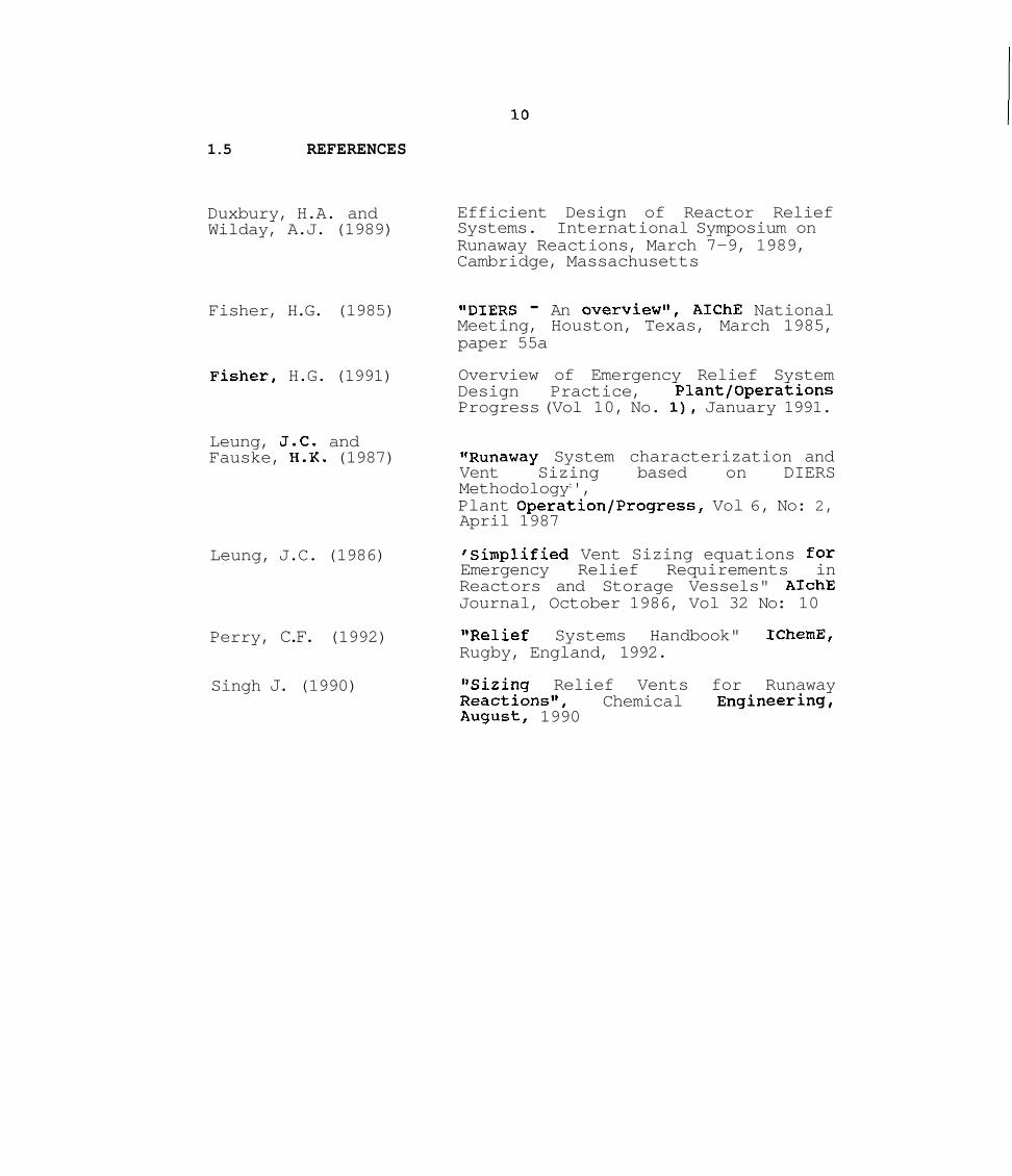
1.5 REFERENCES
Duxbury, H.A. and Wilday, A.J. (1989)
Fisher, H.G. (1985)
ish her, H.G. (1991)
Leung, J.C. and Fauske, H.K. (1987)
Leung, J.C. (1986)
Perry, C.F. (1992)
Singh J. (1990)
Efficient Design of Reactor Relief Systems. International Symposium on Runaway Reactions, March 7-9, 1989, Cambridge, Massachusetts
"DIERS - An overviewst, AIChE National Meeting, Houston, Texas, March 1985, paper 55a
Overview of Emergency Relief System Design Practice, Plantfoperations Progress (Vol 10, No. I), January 1991.
"Runaway System characterization and Vent Sizing based on DIERS Methodologyt', Plant OperationfProgress, Vol 6, No: 2, April 1987
'simplified Vent Sizing equations for Emergency Relief Requirements in Reactors and Storage Vessels" AIchE Journal, October 1986, Vol 32 No: 10
ItRelief Systems Handbook" IChemE, Rugby, England, 1992.
tlSizing Relief Vents for Runaway Reactionstt, Chemical ~ngineering, August, 1990

2. DISPOSAL UNIT SELECTION
2.1 INTRODUCTION
Equipment required to successfully and safely dispose vented reactants is common in the chemical industry and relatively simple in construction.
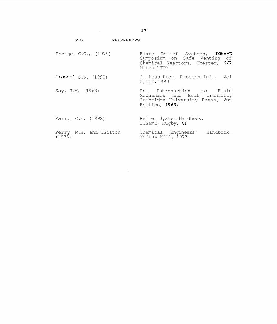
The first choice for controlling vented reactants is likely to be some form of vapour/liquid separation vessel, possibly a simple vertical drum or perhaps a tank which performs the same function but provides space for more liquid. A hypothetical scheme (purely illustrative) is shown in figure 2.1, where the first unit is a simple separator. In the example, when the bulk of the liquid has been separated out, the remaining gas/vapour is vented to a drum containing cold diluent, primarily to condense out the vapours. From here the remaining gas may be sent through a vent condenser where further vapours may be removed.
Final disposal of the remaining gas depends, as indicated in figure 2.1, on the toxicity/flammability hazard and the flow rate. The options available range from relief to atmosphere to dedicated incineration.
2.2 CONTAINMENT/SEPARATION EQUIPMENT
2.2.1 Simple Se~aration drums
Knockout drum, blowdown drum, flash drum, etc. are all similar types of equipment (Perry, 1973, Grossel, 1990). The purpose of each is essentially vapour/liquid separation but the mechanical arrangements can differ considerably. Selection of any particular type of separation drum will largely depend on the vapour quality (i.e. vapour to liquid ratio), pressure, temperature and composition of the vented two-phase mixture.
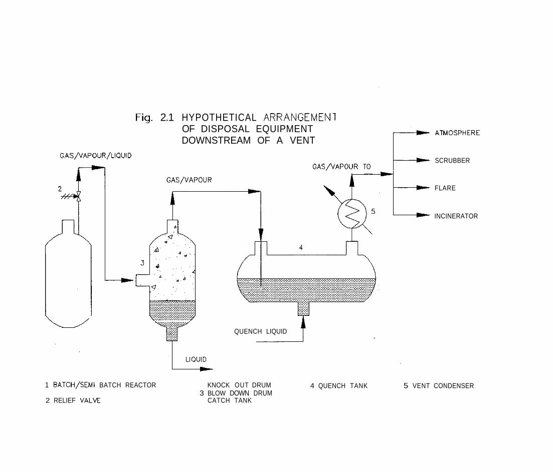
These drums are simple cylindrical vessels (see figure 2.2) which retain the liquid at the bottom and allow the vapour to pass overhead after a phase separation. The vessel may be horizontal or vertical based primarily on two things: space availability and the vapour flow rate. In case of space limitation within the plant or if relatively low vapour rates are involved a vertical type knockout drum can be installed. A vertical drum is always designed with a single inlet and a single vapour outlet.
In a horizontal arrangement, vapour/liquid mixture enters at one end and after separation the vapour leaves from the other end.
In case of a high vapour flow rate, it can be designed with inlets from both ends but with a single vapour outlet from the centre. This type of drum is normally suitable where space limitation is not a problem.
The separation efficiency of both vertical and horizontal drums can be significantly improved by incorporating into their design a wire mesh demister, placed just before the vapour exit.
A more compact and efficient separation can be achieved by the adoption of a cyclone type separator.
2.2.2 Cyclone separator
This type of vessel is frequently used in chemical processing plants for separation of fine particulates particularly where space is limited. The design incorporates a tangential inlet and an internal concentric shroud (Grossel, 1990) which leads to a centrifugal force outward from the centre of the vessel and causes the vapour and liquid (or solid) to separate.
The force (acceleration) separating the vapour/liquid in a cyclone may be several times greater than gravity. This leads to a more compact design with a good separation efficiency. Typically the unit consists of a cylindrical chamber with a central outlet pipe taking the vapours overhead and a conical base for the liquid droplets. The inlet pipe feeds the mixture tangentially thereby providing the necessary centrifugal force
: which leads to the separation.
The unit can be combined with a separate catch tank or an integral tank placed under the separator depending primarily on the quantity of fluid to be processed.
2.2.3 Quench tank
The selection of a quench tank is generally made when the vented reactants have a considerable amount of condensible vapours or, need to be cooled in order to stop further reaction. Two major functions performed by a quench tank are (1) it condenses the vapour by transferring its latent heat of vaporisation to the quench liquid thus reducing the vapour flow; and (2) it reduces the temperature of the vented liquid which minimises the risk of further reaction within the quench pool.
A quench system (see figure 2.3) consists of a simple vessel in which a measured amount of liquid is maintained. The quench liquid selected should ideally have low viscosity and a high specific heat.

A specially designed quencher arm (sparger) with a number of small holes in it is normally mounted inside the vessel. The vented discharge is directed at high velocity through the holes of the sparger to break the vapour up into small jets. Each jet stream comes in contact with the quench liquid leading to both mass and heat transfer and resulting in rapid condensation and cooling.
It is important that the holes in the sparger are large enough not to cause blockage. This is particularly important where small amounts of solid may be present.
Vapour condensation is proved to be efficient when the temperature of the quench fluid is maintained at a minimum of 10°C below the condensation temperature of the vapour.
2.2.4 Vent condenser
This unit (Kay, 1968) is sometimes used to recover small quantities of corrosive or toxic vapours from a large gas stream after initial separation in a knockout drum or equivalent device. The unit is normally a simple shell-and-tube heat exchanger, with the process side (i.e. vented gas) on the tube side and the coolant in the shell side. Thus, similar in principle to a quench tank, circulation of cold fluid causes condensation of vapours. The main difference between condensation in a quench tank and in a vent condenser is, in the former, the vapour directly comes in contact with the quench fluid whereas in the latter case the fluid is separated by a solid tube wall.
The choice of the circulating fluid depends upon the vapour pressure of the vapour to be condensed. In case of low boiling fluids or where the vapour concentration has to be reduced to a low level, a refrigerant may be necessary.
2.3 FINAL DISPOSAL OF GASES AND VAPOURS
After vapour-liquid disengagement, the treatment or disposal of any remaining gas or vapour becomes the primary concern. Several consecutive or alternative options are available for this final step:
. Venting to atmosphere . Scrubbing/absorption . Combustion in a flare . Incineration
2.3.1 venting to atmosphere
This is the most common choice for disposing of unwanted vapours. Typically, vapours from several source vessels are collected in a common header and released at a high elevation through a stack. If a vent line or stack is not used, personnel in the vicinity of the reactor may be exposed to considerable risk. In addition, the environmental pollution aspects must be considered.
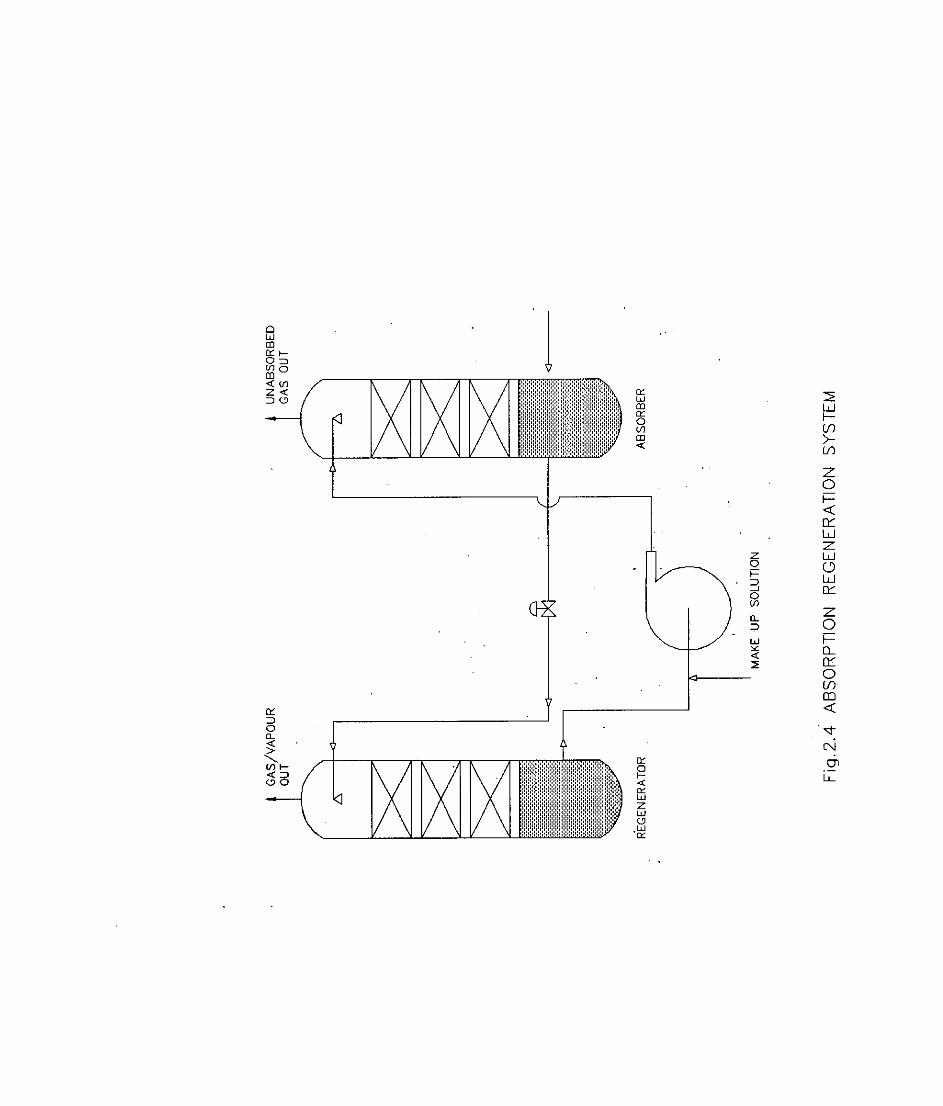
This process (Perry, 1973) is routinely practised in the chemical industry for recovering one or more components from a large gas or vapour stream consisting of several dissimilar components. An example is the removal of CO, during Ammonia production by DETA (diethylene triamine) solution in which CO,,is readily absorbed from a stream of gas and vapours containing CO,, CO, N,, H, and H,O . Scrubbing or absorption is purely a mass transfer phenomenon. The gas or vapour to be absorbed (or 'scrubbed outr) is passed from the bottom of a tower and flows upward while the solvent is pumped and distributed from the top through the distributor and flows downwards by gravity. Counter-current vapour liquid contact takes place leading to the removal of the selected component (See figure 2.4).
Since venting incidents are very rapid, lasting perhaps only a few seconds, the absorber must be kept running at all times. In general this is an expensive option both in terms of operating cost and installation expenses bearing in mind the fact that the emergency vents are rarely used.
2.3.3 Combustion in a flare system
One routinely adopted vapour disposal system used particularly in refineries and large petrochemical plants is the flare (Boeije, 1979). The main function of a flare is combustion, that is, it converts the bulk of combustible gases or vapours into harmless gases such as CO,, H,O and releases them into the atmosphere at elevated temperatures well above ground level.
A flare is primarily a vertical pipe with an auxiliary (pilot) burner at its top which initiates combustion. Based on the types of gases or vapours to be burned, three types of flares are found: 'normal', smokeless and endothermic. A (normal) flare burns fuels such as CH,, H,, NH,, CO etc without forming any smoke; a smokeless flare burns higher hydrocarbons including aromatics and olefins. An endothermic flare is designed to burn low heating value materials.
Flares can also be categorized as ground and elevated types. A ground flare is about 50m high (or less) and is used to process small quantities of gas while elevated flares are typically over 60m high and handle large quantities of combustibles (Grossel, 1990).
Combustion in a flare can create a thermal radiation hazard, noise, discharge hot liquid etc. Therefore the applicability of flares is limited to open, highly industrialized areas. The capital cost of flares is quite high but operating costs are low.
2.3.4 Incineration
Ideally a flare is capable of converting up to about 99% of the vapours (Grossel, 1990) . Frequently however the conversion is much lower and this is particularly true when low heating..value fuels are concerned. In some instances, vented materials are virtually unaffected by flaring and need to be 'chemically treated. '
Incinerators are commonly used to treat chemical streams unsuitable for flaring. They frequently incorporate conversion by catalytic means instead of relying totally on thermal conversion. They are normally compact devices designed for a specific range of chemicals and generally for low flow rates. Both operating costs and installation costs are relatively high compared to a flare (based on a unit mass of gas treated).
The compactness of these units makes them more suitable for smaller sites in built-up areas. However, widespread -use of incinerators for emergency venting is unlikely due to the high cost mentioned above.
2.4 INFLUENCE OF REACTION TYPE ON SELECTION
The various systems discussed above for disposal of reactants are not viable in all cases. Quite apart from the different costs associated with the alternatives, there are technical constraints that may apply depending on the reaction type.
In section 1.3, relief sizing methods were discussed in terms of those applicable to vapour pressure systems and other suited to \gassy1 reactions. The same divisions are suited to disposal unit design.
>i - ,.. In order to completely quench a reaction and contain all vapours, it is necessary that the reaction system is of the vapour pressure (or 'tempered') type. This will ensure that the vented vapours are capable of being condensed in a suitable solvent.
A gassy reaction on the other hand will not be suited to total containment since the gas (e.g. decomposition product) will not be readily condensed. The possibility of serious foaming within the quench vessel as the gas is bubbled through is another important variable that needs to be considered.
The only exception to this is in situations where the solvent in the quench drum readily absorbs the gas. For example if the gas is HC1, this can be readily dissolved in water, but if the gas is N, or 0,, choices are rather limited.
The foaming nature of vented reactants in relation to the use of simple atmospheric knock-out drums should be carefully considered. If the reactants vent out from the reactor in the form of a two-phase mixture, which is normally the case, it is quite likely that the mixture will also vent out of the knock-out drum in a similar manner. Thus, the simple option may not in fact be available in all cases and a detailed evaluation must be carried out.
Another important consideration regarding selection is the possibility of continued reaction in the disposal vessel, following relief. Clearly the reaction must be either slowed down or stopped after relief, otherwise nothing has been achieved. If venting to an atmospheric unit without any quench does not slow down the reaction, then clearly quenching must be applied. In the case of gassy reactions for example, the quench solvent will cool and dilute the vented reactants thus preventing continued gas generation, even though the gas from the reactor is not condensed. The possibility of serious foaming within the quench vessel as the gas is bubbled through is another important variable that must be considered.
2 . 5 REFERENCES
Boeije, C.G., (1979) Flare Relief Systems, IChemE Symposium on Safe Venting of Chemical Reactors, Chester, 617 March 1979.
Grossel S.S. (1990)
Kay, J.M. (1968)
Parry, C.F. (1992)
Perry, R.H. and Chilton (1973)
J. Loss Prev. Process Ind., Vol 3,112,1990
An Introduction to Fluid Mechanics and Heat Transfer, Cambridge University Press, 2nd Edition, 1968.
Relief System Handbook. IChemE, Rugby, UK
Chemical Engineers' Handbook, McGraw-Hill, 1973.
Fia. 2.1 HYPOTHETICAL ARRANGEMENT <
OF DISPOSAL EQUIPMENT DOWNSTREAM OF A VENT
SCRUBBER GAS/VAPOUR TO
QUENCH LIQUID
1 BATCH/SEMI BATCH REACTOR KNOCK OUT DRUM 3 BLOW DOWN DRUM
2 RELIEF VALVE CATCH TANK
4 QUENCH TANK
FLARE
INCINERATOR
5 VENT CONDENSER
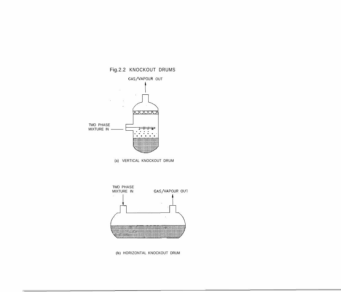
Fig.2.2 KNOCKOUT DRUMS
GAS/VAPOUR OUT
TWO PHASE MIXTURE IN- . . . . * . * . . . . . . . . .
(a) VERTICAL KNOCKOUT DRUM
TWO PHASE MIXTURE IN GAS/VAPOUR OU1
(b) HORIZONTAL KNOCKOUT DRUM
18
3. SPECIFICATION OF DISPOSAL UNITS : THEORETICAL
3.1 STEPS INVOLVED IN SPECIFICATION
Disposal systems (or containment vessels) may be considered as being either open (atmospheric pressure units) or closed (high pressure units). Closed systems must invariably contain some quench fluid, else the reaction will not be suppressed, while atmospheric drums may be either empty knock-out drums or, vessels containing a quench fluid.
In general the following design options are available:
Open (atmospheric) drum without quench (i.e. simple k.0. drum) . Open (atmospheric) drums with quench fluid
Closed (pressure) drum with quench fluid
The design considerations will differ not only according to the above options but will also depend on the reaction type. A division which is helpful, is to consider gassy reactions separately from vapour pressure (tempered) type particularly when
. , empty, atmospheric drums are considered.
There are broadly three assessment stages to consider after initiation of relief, with different parameters being relevant at each stage:
Staae 1 : Initial rapid dump out of Reactor
. equilibrium temperature in drum . vapour/gas generation from drum . downstream liquid carry-over check Stase 2 : Subsequent Reaction within Disposal drum
. reaction rate . vapour/gas generation rate . liquid carry-over check Staae 3 : Final conditions in Disposal drum
. maximum temperature
. maximum pressure Continued reaction in disposal drum (stage 2) should be eliminated by design where possible so that the reaction stops after entering the disposal unit.
It should be noted in the subsequent analysis, hybrid reactions are not specifically considered, only gassy and vapour pressure types are presented.

3.2 SPECIFICATION OF INITIALLY EMPTY DRUM, VAPOUR PRESSURE TYPE REACTION
3.2.1 Flash Va~orization
A vapour~pressure system will be vented when the chemicals are above their atmospheric boiling point (by definition). If the mixture vents as a two-phase froth, the liquid will cool from the reactor temperature T, down to the atmospheric boiling point T,. The energy available due to this cooling will vaporize some of the liquid. If the weight fraction that undergoes flash vaporization is x, then a heat balance of this process gives:
where c, 'is the specific heat of the liquid and 1 the latent heat of vaporization.
Integration between T, and T,, assuming constant C, and 1 gives:
cL (T, - Tb) x = l - e x p ( 3 . la) A
I f x i s s m a l l ( s a y c, ( T , - T,) / A 2 0 . 2 ) then the above equation .
simplifies to:
cL (TI - Tb) x = ( 3 . lb)
. A
Since the relief temperature T, is normally known, the important variable'is T,; this is frequently difficult to calculate because the reactor composition at the point of relief is not known. The best method for estimating T, is experimental.
If the venting rate from the reactor is W (kg/s), then the initial rate of vapour generation due to flash vaporization will be :
The mass of vapour from the reactor will normally be negligible
compared with M~ and so may be neglected.
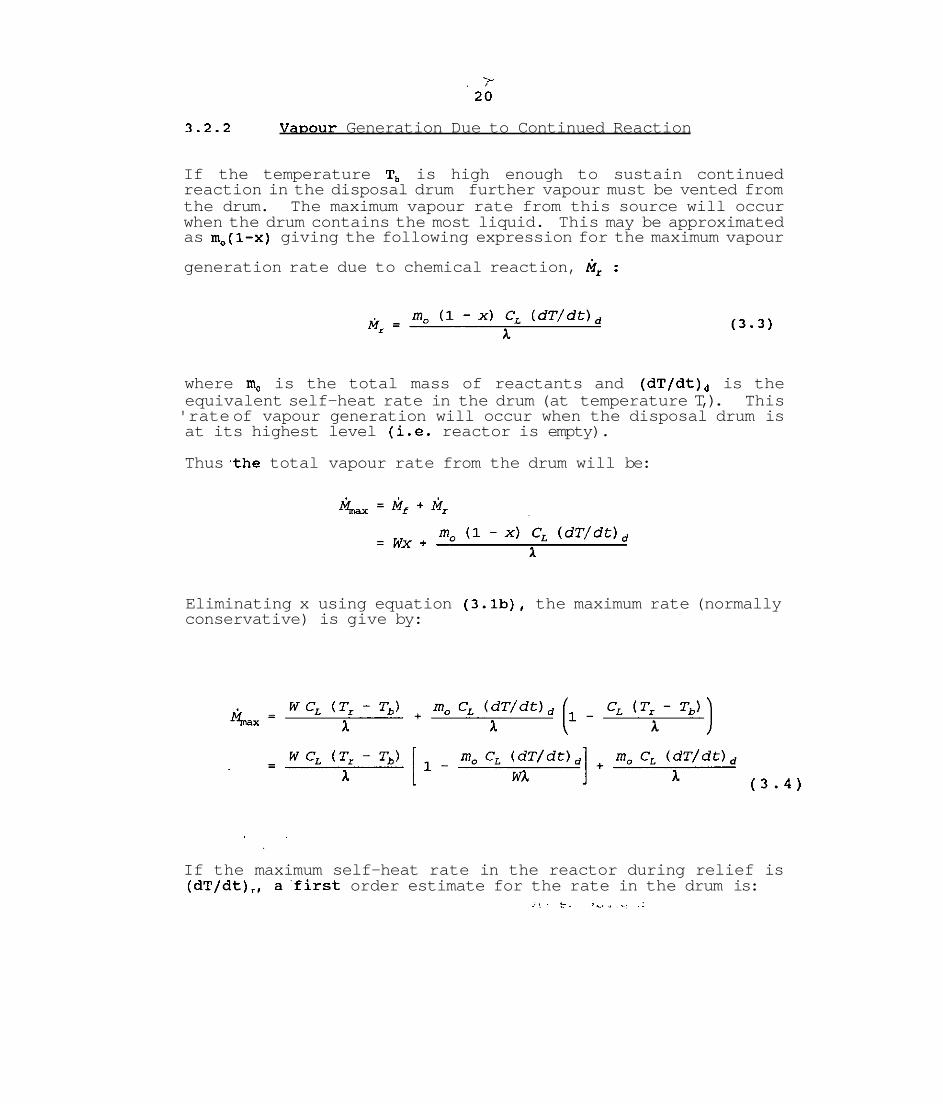
3.2.2 Vavour Generation Due to Continued Reaction
If the temperature T, is high enough to sustain continued reaction in the disposal drum further vapour must be vented from the drum. The maximum vapour rate from this source will occur when the drum contains the most liquid. This may be approximated as m,(l-x) giving the following expression for the maximum vapour
generation rate due to chemical reaction, M~ :
where m, is the total mass of reactants and (dT/dt), is the equivalent self-heat rate in the drum (at temperature T,). This 'rate of vapour generation will occur when the disposal drum is at its highest level (i.e. reactor is empty).
Thus the total vapour rate from the drum will be:
Eliminating x using equation (3.lb), the maximum rate (normally conservative) is give by:
If the maximum self-heat rate in the reactor during relief is (dT/dt),, afirst order estimate for the rate in the drum is:
where E is the activation energy for the reaction and R is the universal gas constant. This is based on the assumption that the reaction follows an Arrhenius type behaviour and that the composition in the drum is the same as that in the reactor.
Ideally, ( d T / d t ) , should be obtained experimentally.
In summary, the vapour rate from the drum will initially be given by equation (3.2) and will rise to a maximum given by equation (3.4). After this, the venting period is complete and so the rate will be just M, as obtained from equation (3.3).
3.2.3 Temwerature and Pressure Variations in Drum
In principle the drum temperature should be close to T, all the time. The object of the design is to ensure that the vapour is removed without overpressurization; since the reaction is of the 'tempered' type, the temperature in the drum will remain at the boiling point of the liquid, T,, and the pressure will remain atmospheric.
3.3 SPECIFICATION OF"INITIALLY EMPTY DRUM FOR GASSY REACTION '
3.3.1 Initial Flashina of Liauid
In a gassy reaction system, the pressure is due almost entirely to the presence of noncondensible gas, ,with negligible contribution from the liquid vapour pressure. It is therefore reasonable to assume that the liquid temperature at the point of venting is below its atmospheric boiling point. Hence, venting into an-atmospheric drum will produce virtually no cooling, the liquid temperature remaining at T,, the reactor temperature, and there will be no vapour generation equivalent to that for a tempered system. (Thus M, in equation 3.2 is zero).
It should be noted that some chemical reactions in practice may exhibit both gassy and vapour pressure characteristics at the same time. In such cases, the initial flash will produce some cooling (see equation 3.1) as the pressure is reduced. Apart from this, the behaviour may be treated as being similar to gassy reactions by regarding the vapour as additional gas.

3.3.2 Gas Generation Rate Due to Continued Reaction'
Since the act of relieving the reactor produces no change in temperature (or composition) the total amount of gas produced will be unaltered. In effect the only change will be that as liquid is vented out of the reactor (together with gas), the source of gas will shift from the reactor to the disposal drum. The total gas rate will remain exactly the same as it would have done in the reactor.
The gas rate must be established experimentally.
The use of a simple knock-out drum for gassy reaction containment is likely to be ineffective. Some form of quench must be provided.
3.3.3 Temuerature and Pressure Variations in Drum
The pressure in the drum will remain close to atmospheric provided the gas can be successfully vented : this is the objective of using an open disposal drum. The gas rate will increase continuously as the exotherm proceeds. The maximum temperature in the drum will be the maximum exothermtemperature, which is best established experimentally.
3.4 SPECIFICATION OF OPEN PASSIVE QUENCH DRUM
3.4.1 Initial Quench Temuerature
Unlike open disposal drums where the temperature in the drum is determined by the physical properties of the reactants, this 'parameter is selected by the designer in the case of quench drums. The selection is based on two simple criteria:
(i) the reactants must be cooled sufficiently to bring the reaction under control; this depends entirely on the reaction kinetics
(ii) condensible vapours from the reactor should be successfully condensed; this generally requires that the final quench drum temperature must be at least 10°C lower than the condensation temperature of the vapour.
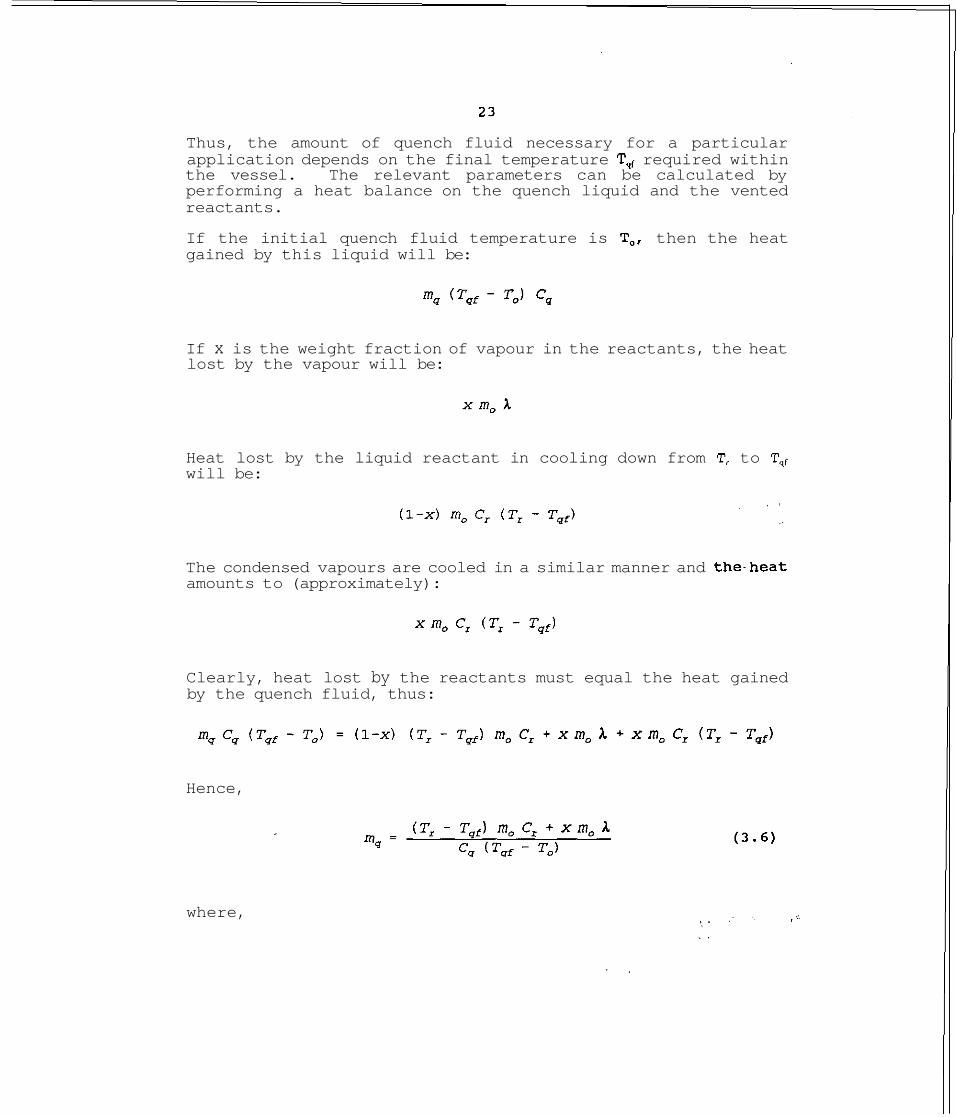
Thus, the amount of quench fluid necessary for a particular application depends on the final temperature Tqf required within the vessel. The relevant parameters can be calculated by performing a heat balance on the quench liquid and the vented reactants.
If the initial quench fluid temperature is To, then the heat gained by this liquid will be:
If x is the weight fraction of vapour in the reactants, the heat lost by the vapour will be:
Heat lost by the liquid reactant in cooling down from T, to T,, will be:
The condensed vapours are cooled in a similar manner and the.heat amounts to (approximately):
Clearly, heat lost by the reactants must equal the heat gained by the quench fluid, thus:
Hence,
where,

mq is the amount of quench fluid, kg m, is the mass of the reactants, kg T, is the temperature of the reactants before entering the
quench tank, "K
Tqf is the final temperature in the quench vessel 'X To is the initial temperature of the quench fluid, 9( C, is the specific heat of reactants J/kgS(
is the specific heat of quench fluid J/kg 'X is the latent heat of vaporization of the reactants, J/kg
Equation (3.6) provides the general expression for calculating the amount of quench fluid needed for a particular duty. This can be simplified somewhat for special cases.
If the amount of vapour condensed is relatively low (i.e. x = 0) then equation (3.6) becomes:
The same result is obtained if A- 0. This would be true for example if the reaction produced non-condensible gas (gassy reaction) and the reactant vapour pressure was low. If there is no liquid reactant vented (i.e. all vapour venting) then x = 1 and,equation (3.6) may be replaced by:
where 6 is the fraction of reactants vented out (in the form of vapour). This ignores sensible cooling of the condensed vapour which will be negligible compared with condensation.
In addition to selecting the correct amount of quench fluid, certain mechanical details must also be observed. Efficient cooling and condensation is achieved by choosing the correct sparge hole diameter. The recommended sparge hole diameters are normally 118 - 318 inches although Keiter has suggested values of around 2" (5 cm) for two-phase mixtures (Keiter, 1989). The total area of the sparge holes should be 1 to 1.5 times the vent line cross section area (Grossel, 1990).
3 . 4 . 2 Gas Flow Out of Drum
Air Disvlacement
The first impact of venting into the quench drum will be to displace the air above the quench fluid; in order to maintain a low pressure in the drum, this must be rapidly removed.
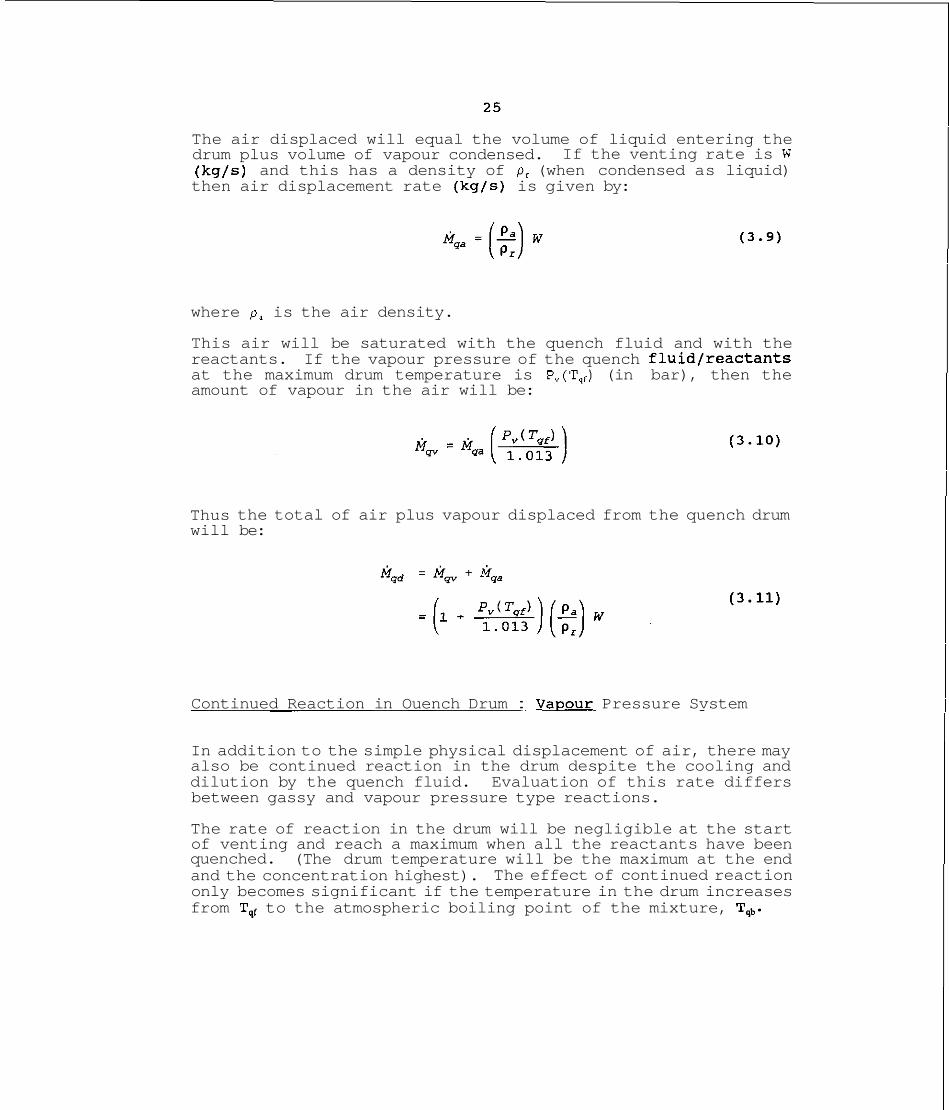
The air displaced will equal the volume of liquid entering the drum plus volume of vapour condensed. If the venting rate is W (kg/s) and this has a density of p , (when condensed as liquid) then air displacement rate (kg/s) is given by:
where p, is the air density.
This air will be saturated with the quench fluid and with the reactants. If the vapour pressure of the quench fluidfreactants at the maximum drum temperature is P,(T,,) (in bar), then the amount of vapour in the air will be:
Thus the total of air plus vapour displaced from the quench drum will be:
Continued Reaction in Ouench Drum : Vapour Pressure Svstem
In addition to the simple physical displacement of air, there may also be continued reaction in the drum despite the cooling and dilution by the quench fluid. Evaluation of this rate differs between gassy and vapour pressure type reactions.
The rate of reaction in the drum will be negligible at the start of venting and reach a maximum when all the reactants have been quenched. (The drum temperature will be the maximum at the end and the concentration highest). The effect of continued reaction only becomes significant if the temperature in the drum increases from Tqf to the atmospheric boiling point of the mixture, Tqb.

The maximum that may actually be reached T, may be estimated from:
where AT, = T,, - T,
T, being the reactor temperature at relief point and T, the maximum exotherm temperature. Thus AT, represents the adiabatic temperature rise.
If T, > Tqb, then clearly the maximum temperature will be limited to Tqb the boiling point and the vapour rate needs to be determined. If T, < Tqb then further calculation is not needed since the mixture never reaches boiling point and the vaporization will be quite small.
If the reaction rate at temperature Tqb is equivalent to a self- heat rate of (dT/dt),, then the amount of vapour produced is:
(provided T, > Tqb) . This is equivalent to equation (3.3) for an open knock-out drum.
The drum outlet pipe will be sized to accommodate Mq, plus Mqd , thus preventing pressure or temperature rise.
It is possible to estimate (dT/dt)g based on the rate in the reaction vessel and the extent of dilution:
where n is the 'order' of the reaction, assuming the rate obeys an Arrhenius type relationship. This is equivalent to equation (3.5) for venting into an empty drum. The preferred and most
reliable approach is to obtain ( d T / d t ) , experimentally. , , %.. - , .:.
Continued Reaction in Ouench Drum : Gassv Reaction
If the reaction is of the gassy type the calculations are rather more complex.
Firstly, the gas vented from the reactor will not condense. Thus, this has to be vented from the quench drum continuously. The second contributor to gas production is any continued reaction from the quench drum itself. This source of gas will depend on whether the quench drum contents boil thus tempering the reaction. Initially (i.e. at T,,) this will certainly not be the case and therefore the temperature will increase. This in turn will lead to continued increase in gas generation. The maximum temperature may be calculated using equation (3.12). The entire process is dynamic and extremely difficult to model accurately.
A practical approach to this problem which will produce a conservative (safe) result is to estimate the two sources of gas as follows:
(a) the maximum gas rate from the reactor Ggr
(b) the additional gas from the quench drum (due to continued reaction).
The first of these is the gas entering the drum; this may be obtained from the information originally used to size the vent. The second source of gas can be estimated in one of the following ways:
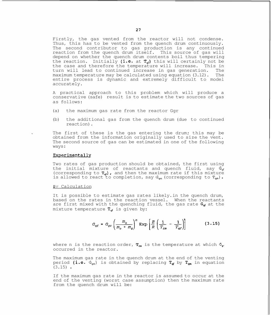
Two rates of gas production should be obtained, the first using the initial mixture of reactants and quench fluid, say Gqf (corresponding to T,,), and then the maximum rate if this mixture is allowed to react to completion, say G,, (corresponding to T,,) . Bv Calculation
It is possible to estimate gas rates likely. in the quench drum, based on the rates in the reaction vessel. When the reactants are first mixed with the quenching fluid, the gas rate G,, at the mixture temperature Tqf is given by:
where n is the reaction order, T, is the temperature at which G, occurred in the reactor.
The maximum gas rate in the quench drum at the end of the venting period (i.e. G,) is obtained by replacing T,, by T, in equation (3.15) . If the maximum gas rate in the reactor is assumed to occur at the end of the venting (worst case assumption) then the maximum rate from the quench drum will be:
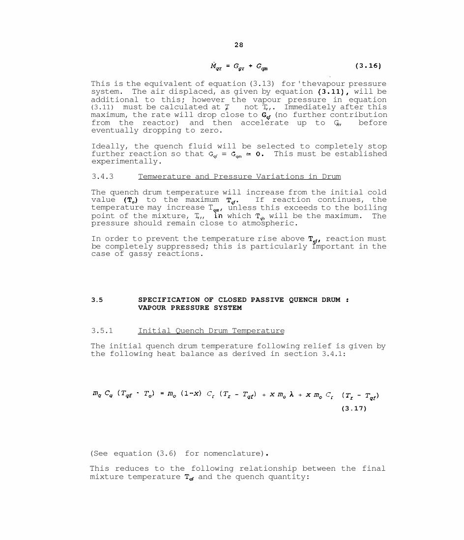
This is the equivalent of equation (3.13) for 'the vapour pressure system. The air displaced, as given by equation (3.11), will be additional to this; however the vapour pressure in equation (3.11) must be calculated at T,, not T,,. Immediately after this maximum, the rate will drop close to Gqf (no further contribution from the reactor) and then accelerate up to G,,, before eventually dropping to zero.
Ideally, the quench fluid will be selected to completely stop further reaction so that G,, = G,= 0 . This must be established experimentally.
3.4.3 Temwerature and Pressure Variations in Drum
The quench drum temperature will increase from the initial cold value (To) to the maximum Tqf. If reaction continues, the temperature may increase T unless this exceeds to the boiling point of the mixture, T,,, Y;;( which T,, will be the maximum. The pressure should remain close to atmospheric.
In order to prevent the temperature rise above Tgf, reaction must be completely suppressed; this is particularly Important in the case of gassy reactions.
3.5 SPECIFICATION OF CLOSED PASSIVE QUENCH DRUM : VAPOUR PRESSURE SYSTEM
3.5.1 Initial Quench Drum Temperature
The initial quench drum temperature following relief is given by the following heat balance as derived in section 3.4.1:
mqc, (Tqf - To) = m , (1-x) C, (TI - Tqf) + xm, A + xm, C, ( T ~ - T ~ ~ )
(3.17)
(See equation (3.6) for nomenclature) . This reduces to the following relationship between the final mixture temperature Tar and the quench quantity:

where r = m,/m,. Using this equation, the reactant/quench mixture temperature can be calculated for any quantity of quench fluid. The vapour fraction, x, is frequently quite small and may be neglected.
3.5.2 Final Ouench Drum Temperature due to continuedReaction
The above temperature (T) represents the quench drum temperature at the end of the venting phase; continued reaction will increase this. The final temperature is determined by the enthalpy still remaining in the vented reactants and this includes the enthalpy of any reaction with the quench fluid, if not inert. This latter quantity can be determined from a knowledge of the heat of reaction, AH,.
The enthalpy already consumed is proportional to the temperature rise at the point of venting, compared with the maximum (adiabatic) available rise. This ratio is, P ,
(Ti is initial temperature at which the exotherm in the reactor started, and A T is the adiabatic temperature rise). The fraction of energy remaining in the reactants is (1 - 6 ) .
An enthalpy balance gives:
where 7 is the mean specific heat of the reactantlquench liquid
mixture. Note that C, AT,, is the heat of reaction, and (I-@) is
the fraction of this energy still available.
3.5.3 Final Ouench Drum Pressure
The pressure P, generated in a closed qudnch drum is given by: P, = Pair + P,

where P,, is the pressure of the air in the drum and P, the vapour pressure of the quenchlreactant mixture.
The value of P, depends on the maximum temperature T, determined from the above equation.
The air pressure results from the compression that takes place as the reactants enter the quench drum. This can be calculated as follows.
If the volume of the quench drum is V and the initial void fraction a,, then the volume of air is a,V and the volume of quench liquid (1 -a,) V. If the total volume of liquid (quench plus reactants vented) is V, then the air volume V, reduces to:
(1 - a,) V + - Pr
where p , is the density of the vented reactant (liquid), p, the density of quench fluid and r = m,/m,.
The final air pressure Pair from an initial pressure Po is:
Thus, unlike the vapour pressure component P,, the air pressure depends on the quantity of quench fluid in relation to the amount of reactants and the initial void fraction in the drum.
'2. : .
3.6 CLOSED (PASSIVE) QUENCH DRUM: GASSY REACTIONS
3.6.1 S~ecial Consideration - Bottom Venting
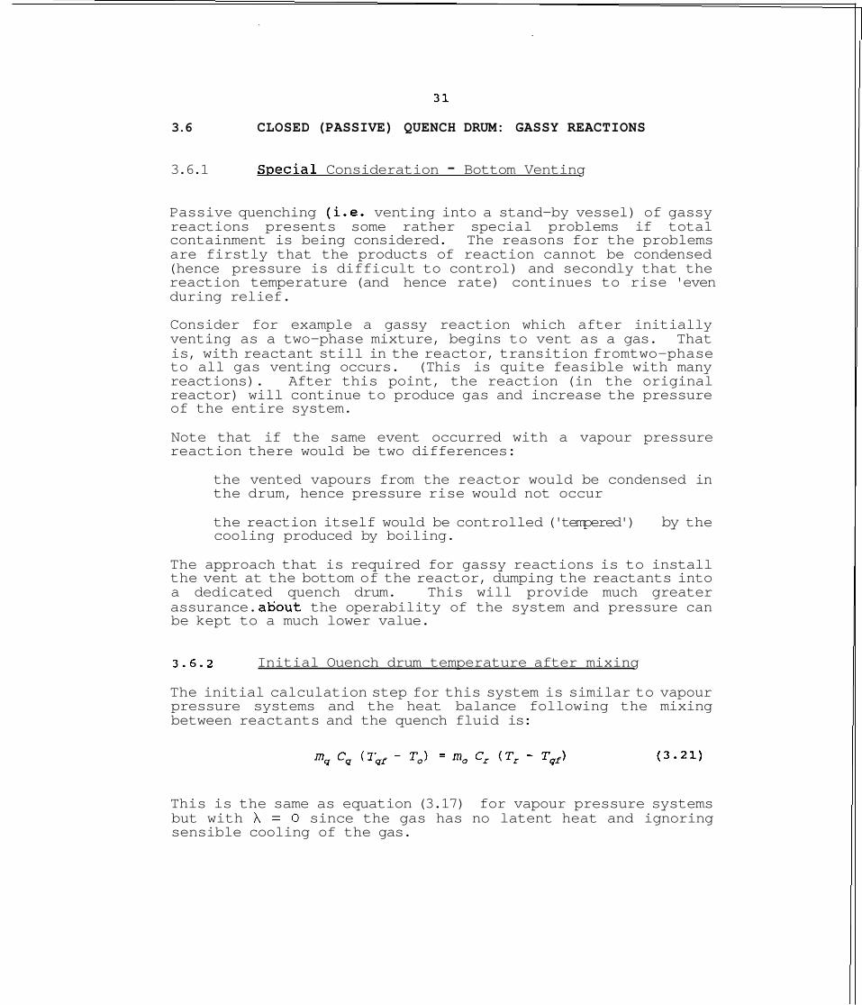
Passive quenching (i.e. venting into a stand-by vessel) of gassy reactions presents some rather special problems if total containment is being considered. The reasons for the problems are firstly that the products of reaction cannot be condensed (hence pressure is difficult to control) and secondly that the reaction temperature (and hence rate) continues to rise 'even during relief.
Consider for example a gassy reaction which after initially venting as a two-phase mixture, begins to vent as a gas. That is, with reactant still in the reactor, transition fromtwo-phase to all gas venting occurs. (This is quite feasible with many reactions). After this point, the reaction (in the original reactor) will continue to produce gas and increase the pressure of the entire system.
Note that if the same event occurred with a vapour pressure reaction there would be two differences:
the vented vapours from the reactor would be condensed in the drum, hence pressure rise would not occur
the reaction itself would be controlled ('tempered') by the cooling produced by boiling.
The approach that is required for gassy reactions is to install the vent at the bottom of the reactor, dumping the reactants into a dedicated quench - drum. This will provide much greater assurance. ahout the operability of the system and pressure can be kept to a much lower value.
3.6.2 Initial Ouench drum temperature after mixing
The initial calculation step for this system is similar to vapour pressure systems and the heat balance following the mixing between reactants and the quench fluid is:
This is the same as equation (3.17) for vapour pressure systems but with h = 0 since the gas has no latent heat and ignoring sensible cooling of the gas.
Thus, the final mixture temperature, T,,, is:
Knowing the relative amounts of reactants and quench fluid (i.e. r), the mixture temperature may be readily determined.
3.6.3 Final Quench Drum Temperature
If the reaction is not totally suppressed by the quenching process, then the temperature will increase above the Tqf given by equation (3.22). The additional temperature rise may be calculated in the same manner as for vapour pressure systems using equation (3.19). This requires knowledge of the adiabatic temperature rise (or alternately the heat of reaction).
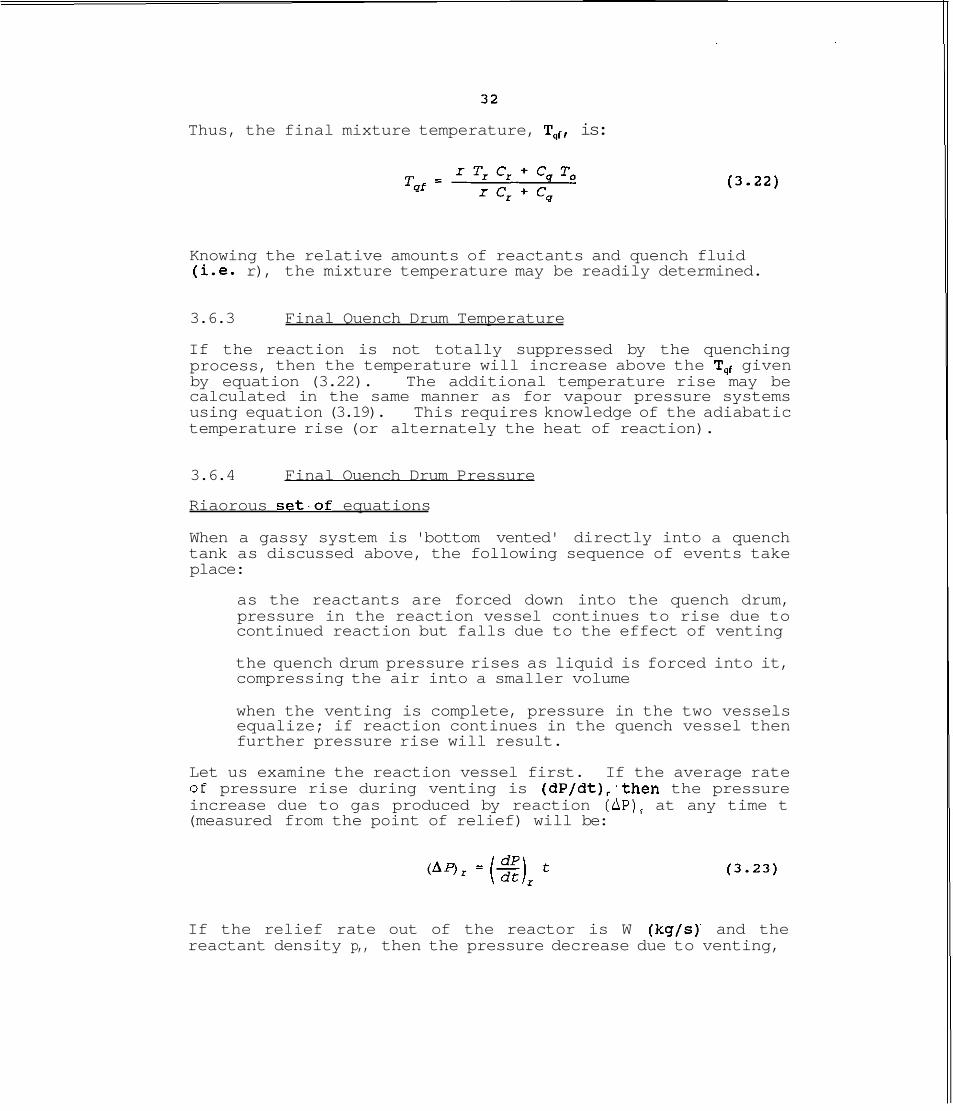
3.6.4 Final Ouench Drum Pressure
Riaorous set,of equations
When a gassy system is 'bottom vented' directly into a quench tank as discussed above, the following sequence of events take place:
as the reactants are forced down into the quench drum, pressure in the reaction vessel continues to rise due to continued reaction but falls due to the effect of venting
the quench drum pressure rises as liquid is forced into it, compressing the air into a smaller volume
when the venting is complete, pressure in the two vessels equalize; if reaction continues in the quench vessel then further pressure rise will result.
Let us examine the reaction vessel first. If the average rate of pressure rise during venting is (dP/dt), ,then the pressure increase due to gas produced by reaction (AP), at any time t (measured from the point of relief) will be:
If the relief rate out of the reactor is W (kg/s) and the reactant density p,, then the pressure decrease due to venting,

3 3
AP, will be proportional to the volume change:
where V, is the volume of the reactor gas space at the point of relief and P, is the relief \setr pressure. (Clearly, V, = a, V,, where a, is the void fraction, and V, the reactor volume).
The actual reactor pressure at time t is therefore given by:
The final.reactor pressure P, just before the end of venting is given by equation (3 . Z 4 ) with t = m,/W.
Turning now to the quench vessel, the pressure at any time is given by compression of the air space:
vao Pair =
where V,, is the initial air volume in the tank and P, is the initial pressure, presumably ambient. At the end of the venting period, the quench drum pressure may be calculated from equation (3.20), previously derived for a vapour pressure system.
The final gas volume will be almost the same as that at the beginning since the net effect of venting is to displace the liquid from the reactor to the dump tank; this volume is (V, + V ) . The air in the quench tank will effectively expand from a volume V,, to (V,, + V,). The reactor gas will expand from V, at the end of venting (pressure P,) to (V, + V,,) . The pressures in the two vessels will equalize and the combined pressure P, is given by:

where P, is the final pressure in the reactor, just prior to completion of venting.
If reaction continues in the quench drum after venting, the pressure will increase above P, as the reaction proceeds.
Solution of Risorous Equations
Design of a quench drum requires simultaneous solution of equations (3.24) and (3.25). This involves stepwise integration as the venting proceeds, calculating the pressure in the reactor (P,) and in the quench drum (P,,,) at each increment until all the reactants have been vented. The venting rate W would also be calculated at each time step, based on the pressure difference between the two vessels. As material is vented out of the reactor, the rate of pressure rise will be reduced : as a conservative assumption this may be ignored. At the end of the venting period pressure equalization between the vessels will occur, changing the pressure to Pf, given by equation (3.26).
It is important to note that (dP/dt), in equations (3.23) and (3.24) relates to the pressure rise in the actual large scale reactor. If data is obtained from a small scale test, this rate must be suitably modified. This is discussed below.
Sim~lified Desisn Procedure
If certain simplifying assumptions are introduced, it is possible to design a quench system without step wise integration. The following points are pertinent to this simplification:
maximum reactor pressure is limited by design; thus, if the vent opens at P,, then the maximum pressure is normally limited to 10% above this. Therefore, P, - 1.1 P,o the quench drum pressure must be kept below the reactor pressure in order to ensure venting. Moreover, to ensure reasonably rapid venting, the pressure difference must be fairly high. Thus, the maximum quench drum pressure P,, can be assigned in relation to the reactor pressure, P,.
The revised design procedure can be reduced to the following steps:
(a) develop an overall quench drum specification using equation 3.25 (or the more versatile, equation 3.20), ensuring'that the maximum pressure (P,,,) is lower than 1.1 P,. (In using equation 3.25, (Wtlp,) may be replaced by the volume of liquid in the reactor, (Vr - VJ)

calculate the time t,, to empty the reactor through the vent, using (1.1 Pro - P,) as the pressure difference (assumed to constant)
obtain the maximum value of (dP/dt) between start of venting and t,
using equation (3.24), with t = t,, calculate the maximum reactor pressure PC. This should be compared with the assumed value (i.e. 1.1 P,).
If the P, (calculated) > 1.1 Po, then two alterations may be made:
change the quench drum design (i.e. make it larger) so as to reduce P,,.
(ii) increase the vent diameter (when possible).
This simple procedure can be repeated until a satisfactory design is obtained.
The crucial data in performing the above calculations is (dP/dt), the pressure rise due to gas generation. If a small scale test is performed using a sample m, and the gas is measured in a volume V,, the experimental pressure rise, (dP/dt), may be scaled- up using the following relationship:
This is quite conservative for two reasons:
(i) the mass in the reactor (m,) goes down as venting proceeds, being zero at the end
(ii) the gas volume (V,) increases as venting proceeds, the eventual volume being V,.
It may be more realistic to use 0.5m0 and 0.5(V, + V,) in place of m, and V,, respectively representing the average values during the venting process.
The experimental equipment from which (dP/dt), is obtained must have certain important features which allow scafing in themabove manner (see chapter 4).

36
3.7 CHECK FOR LIQUID CARRY-OVER
3.7.1 Tvpes of Chemical Svstems
A crucial feature of disposal unit design (except for closed quench systems) is to ensure that vented liquid is not carried over from the disposal vessel. Clearly, this possibility exists because the same phenomenon leads to carry-over in the first place out of the reactor.
The behaviour of most chemicals can be divided into three categories (as discussed in section 1.3.4):
naturally \foamy1 systems
all gas/vapour venting systems,
intermediate systems (bubbly or churn-turbulent)
Whether proper containment in an open disposal drum takes place depends on the design, in relation to the above categories. In the case of foamy systems, an open disposal tank would not be appropriate unless the reaction could be effectively quenched (hence no gas/vapour flow out of the quench drum).
In the case of all gas/vapour venting systems (no liquid carry- over), any type of open disposal unit may be used. A simple atmospheric knock-out vessel is ideally suited for such chemicals. In the case of thermal runaway reactions, chemical systems of this type are quite rare.
A more likely situation is a chemical system fitting the churn- turbulent two-phase behaviour. In such cases, liquid carry-over can be avoided by detailed evaluation of the vessel design in relation to the physical properties of the vented chemicals.
The type of behaviour that may be expected in any situation can only be established from practical experience, either in the plant or experimentally.
Even small scale testing can distinguish between the different types of behaviour and this was verified for a number of reacting and non-reacting systems in the DIERS project (Fisher, 1991).
The DIERS bench-scale tests were performed in a test cell of about 120 cm', the same as that used in the experimental arrangement for the systems studied in this project (see section 4.2.1). The DIERS work showed that by suitable selection of vent diameter on the test cell, vapour velocities comparable with large scale plant can be simulated. When this is done, liquid entrainment (if any) in the bench-scale test is quite reliable for scale-up purposes.
Interpretation of small scale test data is quite simple. The quantity of liquid remaining at the end of a blowdown test is a direct measure of the flow regime. In the case of all vapour venting, the final void fraction in the test cell is around 0.65 while for homogeneous venting, the test cell will be virtually empty. If test cell is around 70 to 80% empty churn-turbulent flow is suggested.
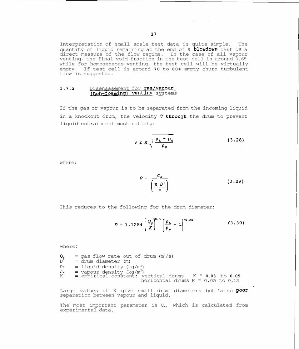
3.7.2 Disensaaement for sas/vavour (non-foamins) ventinq svstems
If the gas or vapour is to be separated from the incoming liquid
in a knockout drum, the velocity Qthrough the drum to prevent
liquid entrainment must satisfy:
where:
This reduces to the following for the drum diameter:
where :
Q, = gas flow rate out of drum (m3/s) D = drum diameter (m) PL = liquid density (kg/m3) Pv = vapour density (kg/m3) K = empirical constant: vertical drums K - 0.03 to 0.05
horizontal drums K - 0.05 to 0.13 Large values of K give small drum diameters but 'also poor separation between vapour and liquid.
The most important parameter is Q,, which is calculated from experimental data.

3.7.3 Check for Two-ohase Flow: Churn-turbulent model
The above method for knock-out drum sizing is based on the assumption that vapour-liquid separation methods experienced in general petrochemical practice, are applicable.
When the chemicals have been found to entrain significant amounts of liquid with gas or vapour, a different approach is needed. Many reacting systems form a stable foam when vented and so invalidate the above equations.
The presence of two-phase (vapour-liquid) flow is assured provided the following inequality holds based on the churn- turbulent model (Leung 1987):
where:
M, = vapour flow (kg/s) '% = initial void 'fraction in drum urn = bubble rise velocity in reaction mixture (m/s) Ax = drum cross-sectional area PP = vapour density (kg/m3)
The bubble rise velocity may be calculated from:
where A, - 1.53, for churn-turbulent systems. a = surface tension p, = liquid density 9 = acceleration due to gravity
Typically, U, is in the range 0.2 to 0.3 m/s although in large scale plant it may be as high as 0.5 m/s.
Application of (3.31) to any system will show whether two-phase flow will occur. If it does, two basic steps can be taken to prevent this:
increase the vessel cross-sectional area (hence reduce vapour velocity)
increase the free-board ( a , ) .
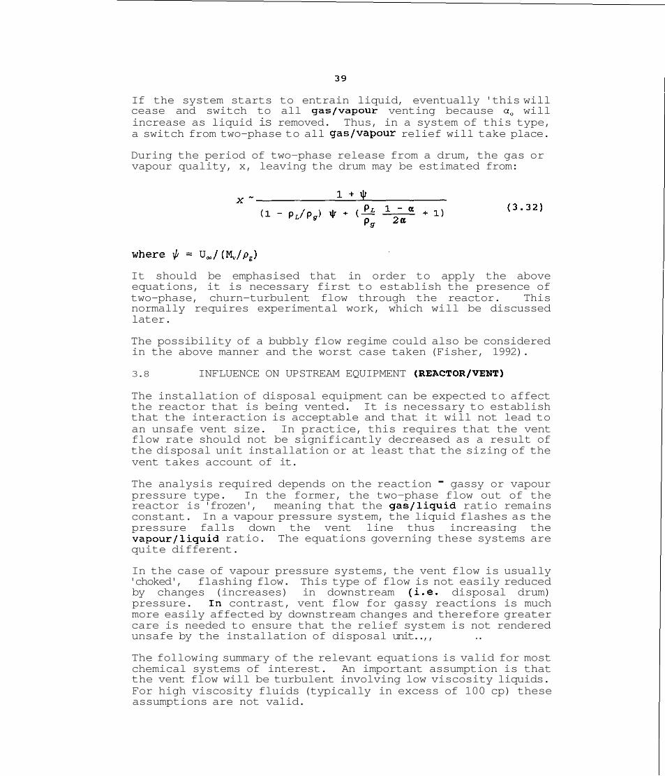
If the system starts to entrain liquid, eventually 'this will cease and switch to all gas/vapour venting because a, will increase as liquid is removed. Thus, in a system of this type, a switch from two-phase to all gas/vapour relief will take place.
During the period of two-phase release from a drum, the gas or vapour quality, x, leaving the drum may be estimated from:
It should be emphasised that in order to apply the above equations, it is necessary first to establish the presence of two-phase, churn-turbulent flow through the reactor. This normally requires experimental work, which will be discussed later.
The possibility of a bubbly flow regime could also be considered in the above manner and the worst case taken (Fisher, 1992).
3.8 INFLUENCE ON UPSTREAM EQUIPMENT (REACTOR/VENT)
The installation of disposal equipment can be expected to affect the reactor that is being vented. It is necessary to establish that the interaction is acceptable and that it will not lead to an unsafe vent size. In practice, this requires that the vent flow rate should not be significantly decreased as a result of the disposal unit installation or at least that the sizing of the vent takes account of it.
The analysis required depends on the reaction - gassy or vapour pressure type. In the former, the two-phase flow out of the reactor is 'frozen', meaning that the gas/liquid ratio remains constant. In a vapour pressure system, the liquid flashes as the pressure falls down the vent line thus increasing the vapour/liquid ratio. The equations governing these systems are quite different.
In the case of vapour pressure systems, the vent flow is usually 'choked', flashing flow. This type of flow is not easily reduced by changes (increases) in downstream (i.e. disposal drum) pressure. In contrast, vent flow for gassy reactions is much more easily affected by downstream changes and therefore greater care is needed to ensure that the relief system is not rendered unsafe by the installation of disposal unit..,, . .
The following summary of the relevant equations is valid for most chemical systems of interest. An important assumption is that the vent flow will be turbulent involving low viscosity liquids. For high viscosity fluids (typically in excess of 100 cp) these assumptions are not valid.
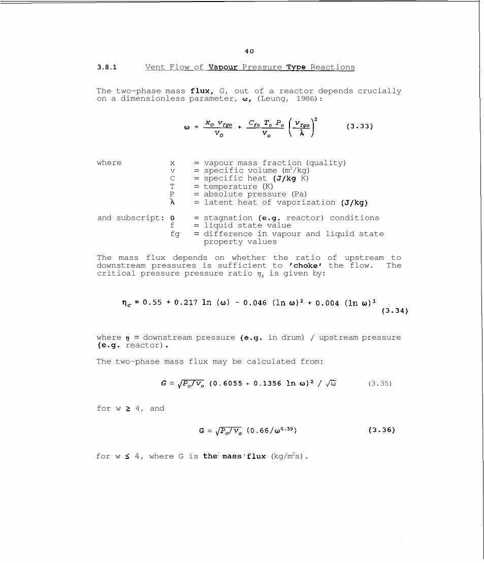
3.8.1 Vent Flow of Va~our Pressure Tvwe Reactions
The two-phase mass flux, G, out of a reactor depends crucially on a dimensionless parameter, a, (Leung, 1986):
where x = vapour mass fraction (quality) v = specific volume (m3/kg) C = specific heat (J/kg K) T = temperature (K) P = absolute pressure (Pa) A = latent heat of vaporization (J/kg)
and subscript: 0 = stagnation (e.g. reactor) conditions f = liquid state value fg = difference in vapour and liquid state
property values
The mass flux depends on whether the ratio of upstream to downstream pressures is sufficient to 'chokef the flow. The critical pressure pressure ratio 7, is given by:
where 7 = downstream pressure (e.g. in drum) / upstream pressure (e.g. reactor) . The two-phase mass flux may be calculated from:
G = (0.6055 + 0.1356 in o)2 / Ji3 (3.35)
for w 2 4, and
G = no (0.66/a0.39)
for w s 4, where G is the'mass.flux (kg/m2s).
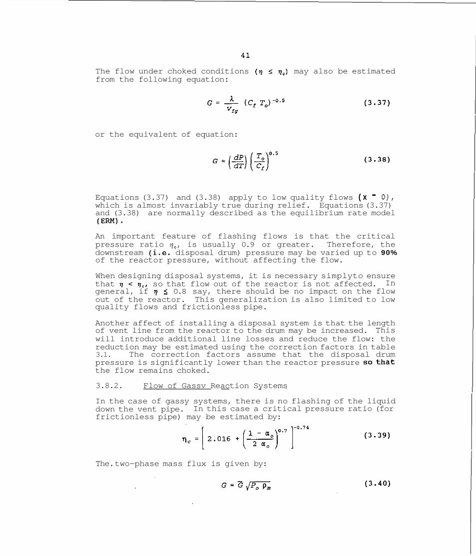
The flow under choked conditions (q S qc) may also be estimated from the following equation:
or the equivalent of equation:
Equations (3.37) and (3.38) apply to low quality flows ( x - O ) , which is almost invariably true during relief. Equations (3.37) and (3.38) are normally described as the equilibrium rate model (Em).
An important feature of flashing flows is that the critical pressure ratio q,, is usually 0.9 or greater. Therefore, the downstream (i.e. disposal drum) pressure may be varied up to 90% of the reactor pressure, without affecting the flow.
When designing disposal systems, it is necessary simplyto ensure that 7 < q,, so that flow out of the reactor is not affected. In general, if 7 < 0.8 say, there should be no impact on the flow out of the reactor. This generalization is also limited to low quality flows and frictionless pipe.
Another affect of installing a disposal system is that the length of vent line from the reactor to the drum may be increased. This will introduce additional line losses and reduce the flow: the reduction may be estimated using the correction factors in table 3.1. The correction factors assume that the disposal drum pressure is significantly lower than the reactor pressure sothat the flow remains choked.
3.8.2. Flow of Gassv Reaction Systems
In the case of gassy systems, there is no flashing of the liquid down the vent pipe. In this case a critical pressure ratio (for frictionless pipe) may be estimated by:
The. two-phase mass flux is given by:
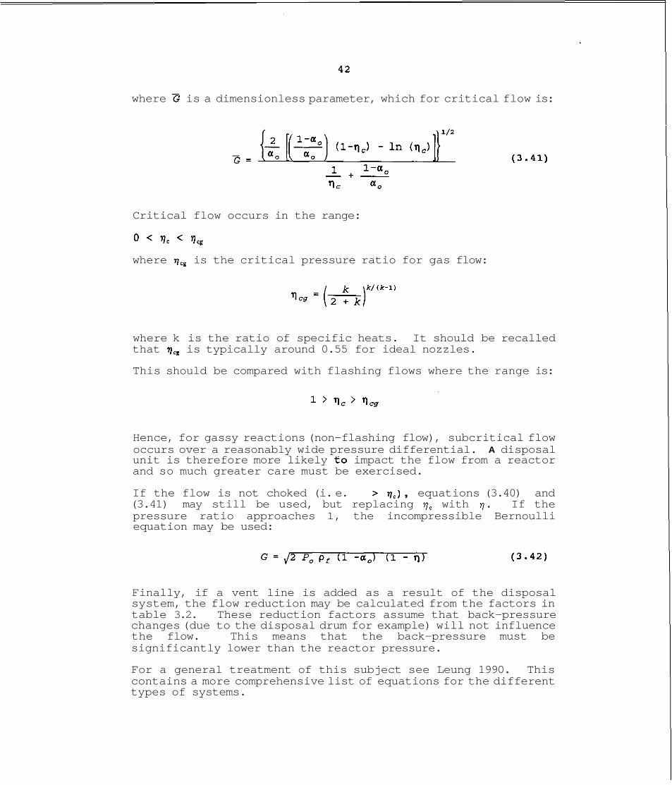
where G is a dimensionless parameter, which for critical flow is:
Critical flow occurs in the range:
0 < 'lc < 'leg
where 7, is the critical pressure ratio for gas flow:
where k is the ratio of specific heats. It should be recalled that 7, is typically around 0.55 for ideal nozzles.
This should be compared with flashing flows where the range is:
Hence, for gassy reactions (non-flashing flow), subcritical flow occurs over a reasonably wide pressure differential. A disposal unit is therefore more likely to impact the flow from a reactor and so much greater care must be exercised.
If the flow is not choked (i. e. > ) , equations (3.40) and (3.41) may still be used, but replacing 7, with 7. If the pressure ratio approaches 1, the incompressible Bernoulli equation may be used:
Finally, if a vent line is added as a result of the disposal system, the flow reduction may be calculated from the factors in table 3.2. These reduction factors assume that back-pressure changes (due to the disposal drum for example) will not influence the flow. This means that the back-pressure must be significantly lower than the reactor pressure.
For a general treatment of this subject see Leung 1990. This contains a more comprehensive list of equations for the different types of systems.
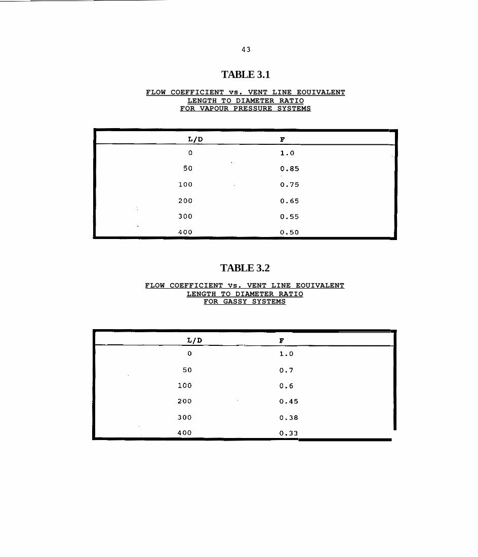
TABLE 3.1
FLOW COEFFICIENT VS. VENT LINE EOUIVALENT LENGTH TO DIAMETER RATIO
FOR VAPOUR PRESSURE SYSTEMS
TABLE 3.2
FLOW COEFFICIENT VS. VENT LINE EOUIVALENT LENGTH TO DIAMETER RATIO
FOR GASSY SYSTEMS

REFERENCES
Fisher, H.G. (1991)
Fisher, H.G. (1992)
Keiter, A.G. (1989)
Leung, J.C. (1987),
Leung, J.C. (1986),
Leung, J.C. (1990),
Overview of Emergency Relief System Design Practice, Plant/Operations Progress, (Vol 10, No: I), January 1991.
~mergency Relief System Design using DIERS Technology, AIChE, New York
Emergency Pressure Relief Discharge Control by Passive Quenching, Int. Symposium on R u n a w a y R e a c t i o n s , Cambridge, 7-9 March.
AIChE Journal, Vol 33, No. 6, June 1987.
AIChE Journal, Vol 33, No. 10, October 1986.
J Loss Prevention in the Process Ind., Vol 3, 27 -32, January 1990.

45
4. ROLE OF BENCH-SCALE TESTING
4.1 PRIMARY OBJECTIVES
Experimental testing plays a very important role in both the understanding of runaway reactions, and the design of related safety features such as relief vents. The types of instruments useful for relief sizing (and by suitable extension also for disposal unit design) have features in common with devices used for hazard screening but also some items that are rather special.
Most instruments are based on the principle of adiabatic calorimetry. This ensures that when a sample undergoes exothermic reaction (leading to an increase in temperature) that heat is not lost from the sample. This is a somewhat 'extreme' case because in practice, large scale vessels will lose some heat. However, the heat losses from large units are so small that an adiabatic assumption is quite justified.
In addition to heat loss to the surroundings, another important feature is the heat retained by the sample container. The thermal capacity of small sample cells used experimentally can be quite large compared with that of the sample : the net effect is the same as heat loss to the environment. Data for relief system design needs to be free of this effect so that rates of temperature and pressure rise are representative of full scale plant.
When relief devices have to be extended to include downstream disposal, the objective of adiabatic calorimetry has to be extended to the disposal unit. Also, the extended unit'must use test cells of low thermal capacity.
Thus, in order to study relief of runaway reactions and their disposal, it becomes necessary to have two somewhat similar adiabatic units directly connected. The original runaway reaction can then be initiated in one unit and then, at the appropriate point, vented into the disposal cell. The latter may contain a quench fluid for example, and so the reaction of the mixture can be studied.
From a practical viewpoint, operating two adiabatic units can be rather difficult. Also, as most modern calorimeters are computer controlled, the combined facility used must be run from the same computer which can display the relevant data from both test cells.
4.2 EXAMPLES OF POTENTIALLY SUITABLE DEVICES
Three units are described which illustrate the type.of equipment that may be suitable, although in some cases modifications may be needed before it can be used for disposal assessment.
4.2.1 DIERS Vent Sizina Device (ref Fauske and Leunq. 19851
The DIERS research project developed the basis for a test instrument which later became known as the Vent Sizing Package (VSP) . Key features of the apparatus are summarized in figure 4.1. The 120 ml thin-walled test cell is placed in a 4 litre high pressure containment vessel. The apparatus indicates sample temperature (TI) and pressure (PI) and external (guard) temperature (T2) and containment vessel pressure (P2). The test cell is enclosed by two heater elements which are in turn enclosed by thermal insulation material. The purpose of the inside auxiliary heater is to heat the test sample to a desired temperature. During a search and subsequent runaway period, the test auxilkary heater is turned off andthe outside guard heater is regulated to keep an outer aluminium can at the same temperature (T2) as the test cell temperature (TI), thus providing close to an adiabatic runaway condition.
The guard heater temperature is maintained by a simple on/off control routine. The VSP'apparatus has been commercialized and a number of units exist worldwide.
In order to study vent disposal parameters, a number of additional features are needed, both hardware and software. These will be described separately in section 4.3.
4.2.2 HEL Adiabatic Device : PHI-TEC I1 [ref Sinsh, 19891
The PHI-TEC I1 calorimeter was developed after the VSP and therefore incorporates some features of the DIERS work. In particular, the use of low thermal mass (i.e. thin-walled) test cells has been retained, using pressure compensation with N, to prevent test cell rupture. In all other respects PHI-TEC I1 is quite different in scope and flexibility.
A diagram of the unit is shown in figure 4.2. The main features are :
a thin-walled test cell (similar to VSP),
three independently controlled and separately monitored guard heaters

PID control of guard heaters
software written in Pascal
the possibility of adding a disposal unit, incorporated in the same software.
The additional design features allow the unit to be used for accurate detection of exotherms (down to about 0.02"C/min) as well as tracking at extremely rapid rates.
More important for the present project, a facility to extend the application to include a disposal facility is included. This will be discussed in section 4.3.
4.2.3 Adiabatic Dewar (ref Gibson et.al. 1987)
The use of a vacuum flask (so called Dewar method) has been traditionally used to determine the exotherm onset temperature of reactions at ambient pressure. This principal has been extended (for example by ICI) to allow the adiabatic tracking of reactions after onset and work at pressure (ref Gibson et.al. 1987).
A schematic diagram of the adiabatic pressure dewar apparatus is shown in figure 4.3. The apparatus comprises a stainless steel flask fitted with mechanical stirrer, bursting disc, thermocouple, pressure transducer and electrical heater. Provision can also be made for remote addition of chemicals during the test sequence.
The peak pressure in the system is limited by the mechanical seals but typical values exceed 35 bar. The thermal inertia of the test vessel is slightly higher than the test cells used in the VSP or PHI-TEC 11.
4.3 EXTENSION TO RELIEF DISPOSAL ASSESSMENT (ref Singh 6 Boey 1991)
In order to use any of the above instruments for relief disposal testing it is necessary to provide an extension. The PHI-TEC I1 has such a feature already included and this will be described .. to illustrate the basic requirements. In principal, a similar extension could be added to the other instruments.
4.3.1 Purpose of PHI-TEC Disposal Unit
The objective of the disposal unit is to allow the assessment of suitable external containment systems for reactive chemicals vented in an emergency. Tests provide sufficient data firstly to decide on the type of containment system feasible and secondly to evolve a detailed specification.
The following types of information can be obtained from application of the unit:
amount of reactants vaporized after venting down to atmospheric pressure
minimum temperature needed for condensation of reactants
amount and type of quench fluid suitable under the relief conditions
reaction rate and pressure following relief into a suitable disposal unit.
The mechanical components fit on to the PHI-TEC I1 unit and are controlled from the same software (suitably extended with additional features).
4.3.2 Hardware of Comaonents of Diswosal Unit
The disposal unit package consists of the following (see figure 4 . 4 ) :
containment vessel plus fittings
guard heater, with heating coil and thermocouple
disposal cell with pressure transducer and thermocouple
electronics to provide:
- amplification of thermocouple signals - amplification of pressure transducer signal - control of guard heater temperature - control of spare auxiliary heater - control of optional solenoid valves
Containment Vessel
The main body of this unit consists of a cylindrical stainless pipe section (schedule 80 pipe, test pressure 170 bar) to which an end cap has been welded.
This forms the bottom section which holds the disposal test cell. The top part of the vessel is again an end-cap designed to be simply placed on top of the main body and tightened by means of the screw assembly fitted.
Guard Heater
The guard heater fits inside the containment vessel and is also constructed in two parts. The lower large section of the heater is housed within the cylindrical part of the vessel and the smaller flat heater is placed on top.
The two heaters are connected in series, outside the containment vessel.
Disposal Cell
The vented reactants from the reaction cell within PHI-TEC I1 are flashed into a similar container, the disposal cell, which is placed between the guard heaters. Two pipes (normally 1/8" diameter) are fitted to the cell, one is connected to the vent pipe from the reaction cell and the other acts as a vent pipe and also as the pressure transducer connection. These pipes should be heat traced. The volume of the disposal cell may be up to 2.5 times that of the reaction cell within PHI-TEC 11.
5 0
4 . 4 REFERENCES
Fauske, H.K. and Leung, J.C. (1985),
Chemical Engineering Progress, August 1985.
Gibson, N., Rogers, R.L., Hazards from Pressure: Exothermic Wright, T.K., (1987), Reactions, Unstable Substances,
Pressure Relief and Accidental isc charge, Inst. Chem. Engineers, Symposium Series No: 102.
Singh, J. (1989),
Singh, J. and Boey D. (1991)
~nternational Symposium Runaway Reaction, March 7-9, 1989, Cambridge, Massachussets.
Plant Operations Progress, Vol. 10, No. 1, January 1991
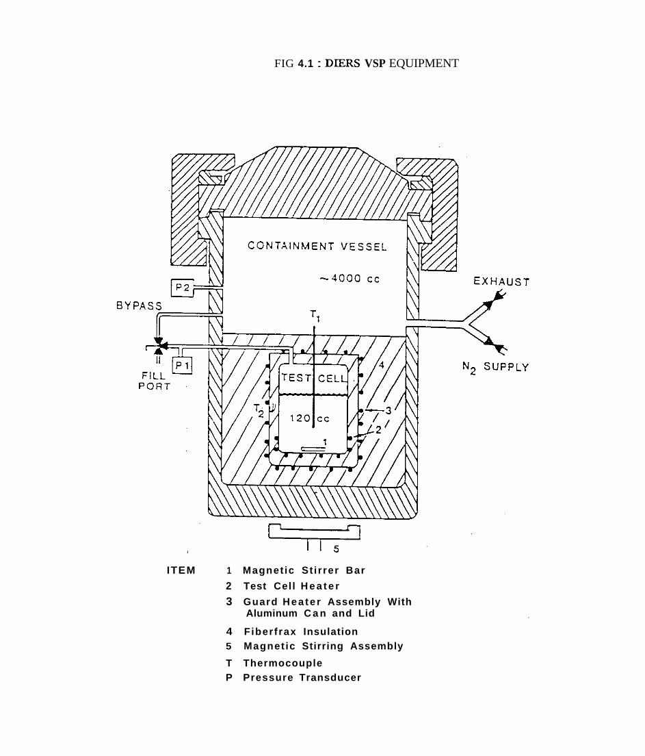
FIG 4.1 : DIERS VSP EQUIPMENT
ITEM 1 Magnet ic St i rrer Bar
2 Test Cell H e a t e r
3 Guard Hea te r Assembly With Aluminum C a n and Lid
4 Fiberfrax Insulation 5 Magnet ic Stirring Assembly
T Thermocouple P Pressure Transducer
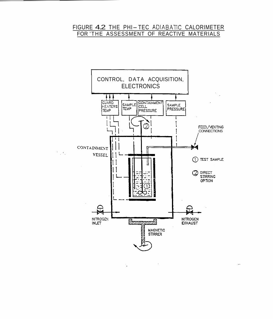
FIGURE 4.2 THE PHI-TEC ADIABATIC CALORIMETER FOR 'THE ASSESSMENT OF REACTIVE MATERIALS
CONTROL, DATA ACQUISITION, ELECTRONICS
rn/VENTING CONNECTIONS
' I . .
OPTiON
MACNETlC STIRRER
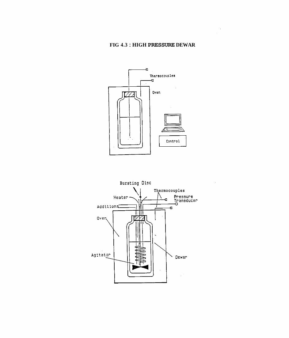
FIG 4.3 : HIGH PRESSURE DEWAR
Control rn L--.--J
Bursting Disc \ I Thermocouples

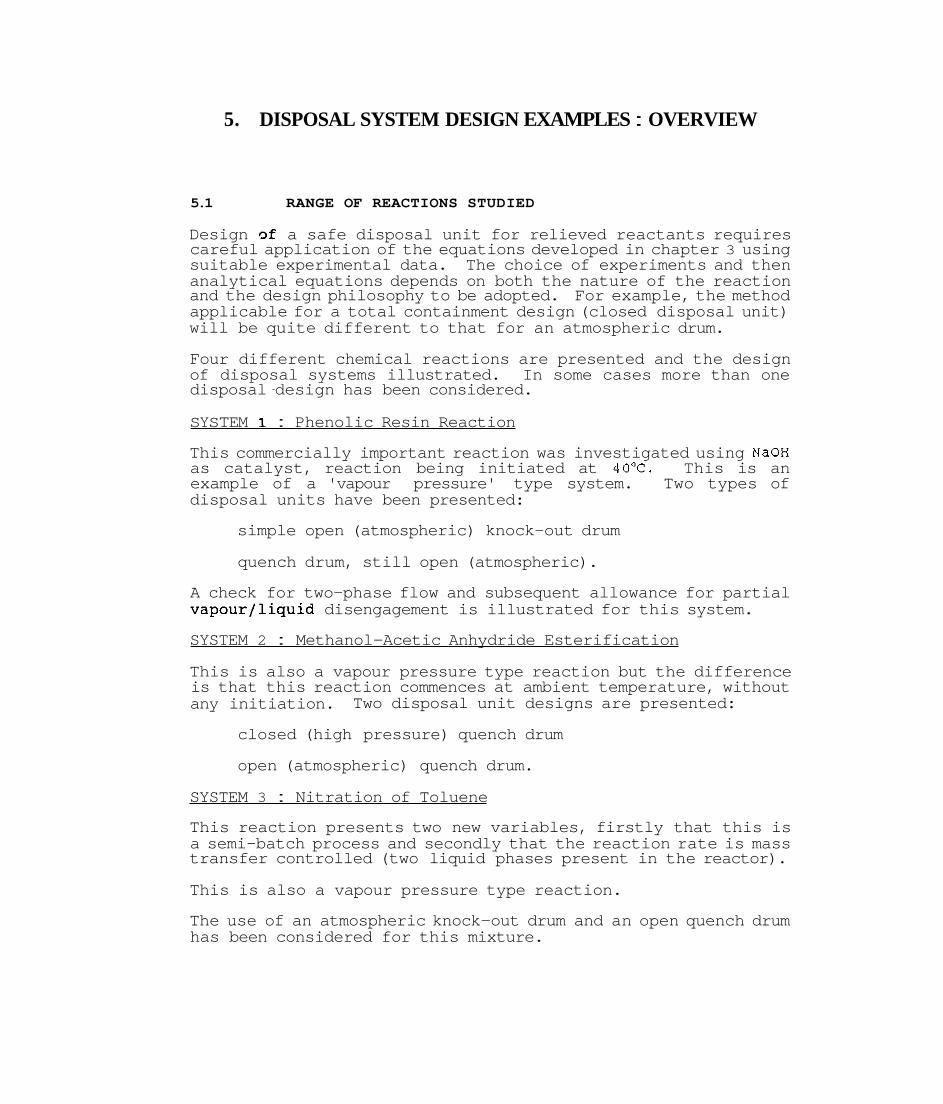
5. DISPOSAL SYSTEM DESIGN EXAMPLES : OVERVIEW
5.1 RANGE OF REACTIONS STUDIED
Design ~f a safe disposal unit for relieved reactants requires careful application of the equations developed in chapter 3 using suitable experimental data. The choice of experiments and then analytical equations depends on both the nature of the reaction and the design philosophy to be adopted. For example, the method applicable for a total containment design (closed disposal unit) will be quite different to that for an atmospheric drum.
Four different chemical reactions are presented and the design of disposal systems illustrated. In some cases more than one disposal -design has been considered.
SYSTEM 1 : Phenolic Resin Reaction
This commercially important reaction was investigated using NaOH as catalyst, reaction being initiated at 40°C. This is an example of a 'vapour pressure' type system. Two types of disposal units have been presented:
simple open (atmospheric) knock-out drum
quench drum, still open (atmospheric).
A check for two-phase flow and subsequent allowance for partial vapour/liquid disengagement is illustrated for this system.
SYSTEM 2 : Methanol-Acetic Anhydride Esterification
This is also a vapour pressure type reaction but the difference is that this reaction commences at ambient temperature, without any initiation. Two disposal unit designs are presented:
closed (high pressure) quench drum
open (atmospheric) quench drum.
SYSTEM 3 : Nitration of Toluene
This reaction presents two new variables, firstly that this is a semi-batch process and secondly that the reaction rate is mass transfer controlled (two liquid phases present in the reactor).
This is also a vapour pressure type reaction.
The use of an atmospheric knock-out drum and an open quench drum has been considered for this mixture.

5 2
SYSTEM 4 : Decom~osition of Hydroqen Peroxide
This reaction was induced by addition of metal ions to a 10% solution of H,O, which produced a gassy reaction. The possible use of an atmospheric knock-out drum and a quench drum is illustrated.
TYPICAL EXPERIMENTS REQUIRED
5.2.1 Test Apparatus
All experiments needed to specify the above disposal systems were conducted in the PHI-TEC I1 calorimeter described in chapter 4 , together with the disposal unit extension.
5.2.2 Ranqe of Tests
The information that is typically required to analyze a disposal unit is the following:
nature of runaway reaction to be vented
- pressures and temperatures involved - rates of pressure and temperature rise
- type of reaction (gassy, tempered etc). two-phase vapour liquid flow out of vented vessel and likely behaviour in disposal drum
consequences of venting with empty (atmospheric) drum
effect of quench in open drum
potential for a totally enclosed disposal unit
When data specifically related to a disposal unit is required, it is necessary to fit an extension to the normal PHI-TEC I1 device. This extension also contains a light-weight test cell and simple facility to avoid heat loss. Thus the 'post venting' period of chemicals after leaving the PHI-TEC test cell, may be examined.
The following tests are frequently required, depending on the actual problem:
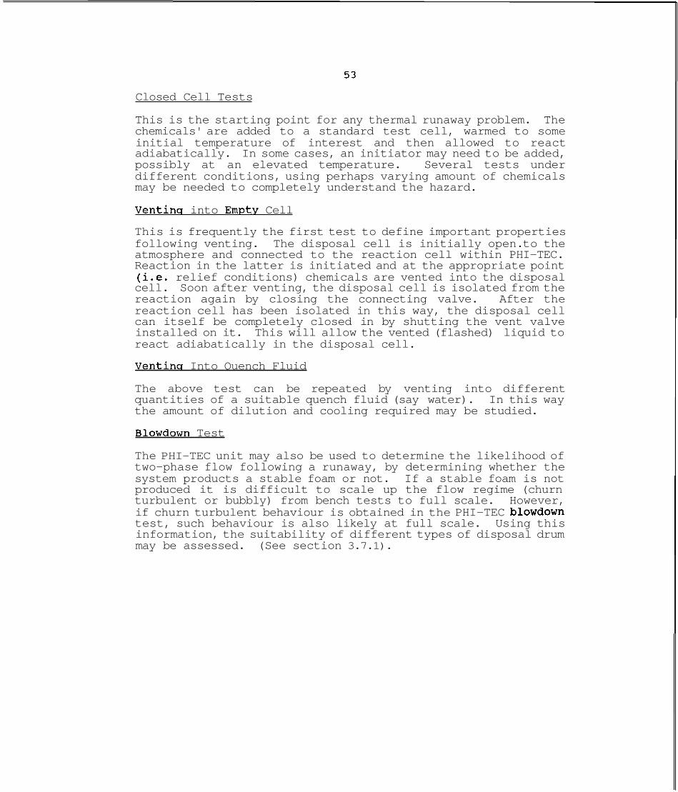
Closed Cell Tests
This is the starting point for any thermal runaway problem. The chemicals' are added to a standard test cell, warmed to some initial temperature of interest and then allowed to react adiabatically. In some cases, an initiator may need to be added, possibly at an elevated temperature. Several tests under different conditions, using perhaps varying amount of chemicals may be needed to completely understand the hazard.
Ventina into Empty Cell
This is frequently the first test to define important properties following venting. The disposal cell is initially open. to the atmosphere and connected to the reaction cell within PHI-TEC. Reaction in the latter is initiated and at the appropriate point (i.e. relief conditions) chemicals are vented into the disposal cell. Soon after venting, the disposal cell is isolated from the reaction again by closing the connecting valve. After the reaction cell has been isolated in this way, the disposal cell can itself be completely closed in by shutting the vent valve installed on it. This will allow the vented (flashed) liquid to react adiabatically in the disposal cell.
Ventins Into Quench Fluid
The above test can be repeated by venting into different quantities of a suitable quench fluid (say water). In this way the amount of dilution and cooling required may be studied.
Blowdown Test
The PHI-TEC unit may also be used to determine the likelihood of two-phase flow following a runaway, by determining whether the system products a stable foam or not. If a stable foam is not produced it is difficult to scale up the flow regime (churn turbulent or bubbly) from bench tests to full scale. However, if churn turbulent behaviour is obtained in the PHI-TEC blowdown test, such behaviour is also likely at full scale. Using this information, the suitability of different types of disposal drum may be assessed. (See section 3.7.1).

6. EXAMPLE 1 : PHENOLIC REACTION
6.1 INTRODUCTION
The chemical system studied in this chapter is commercially important involving the production of a phenolic resin by reacting phenol and formaldehyde in the presence of a suitable initiator.
6.2 OVERVIEW OF PHENOLIC REACTION CHEMISTRY
<
The manufacture of resins is wi'dely practised in the chemical industry frequently by small to medium sized companies located in semi-residential areas. Phenolic resins are recognised as involving a highly exothermic reaction and as a result have attracted considerable attention.
The production of phenolics involves reaction between phenol and formaldehyde using a suitable catalyst, typically an acid or base. Phenol can react with formaldehyde by addition to give a phenol alcohol, or by condensation to give a methylene bridged compound. While both reactions are exothermic, the reaction to alcohol produces only about 17.2 kJ/mole of heat whereas the condensation reaction generates about 91 kJ/mole (Booth et.al. 1980). The type of reaction, methylonation or condensation, and the rate is determined by the normal reaction control variables (catalyst type and concentration, temperature etc) and this also influences the particular grade of resin produced. Typical reaction temperatures range between 40 and 90°C, nominally atmospheric pressure and formaldehyde is normally in excess (on a mole to mole basis).
The underlying reactionchemistry has been studied extensively and some generalizations are possible. The acid catalysed reaction is reported as being second order, above 3OoC. The precise kinetics vary with the acid and pH values and therefore from a hazard viewpoint, consequence prediction is difficult without specific tests.
Base catalysed reactions show greater variability: first, second and fractional order reactions have been reported. The activation energy of these reactions is quoted as being about 73.3 to 81.6 kJ/mole. Once again, meaningful hazard evaluation of a particular resin requires specific testing.
The present study will evaluate base catalysed reaction, primarily NaOH but also ammonia for comparison.
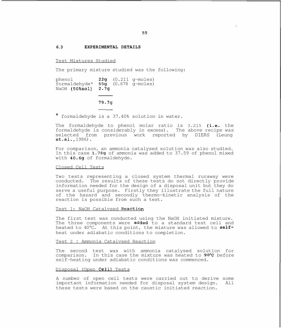
6.3 EXPERIMENTAL DETAILS
Test Mixtures Studied
The primary mixture studied was the following:
phenol 229 (0.211 g-moles) formaldehyde* 559 (0.678 g-moles) NaOH (50%~0l) 2.7g
79.7g -
* formaldehyde is a 37.40% solution in water. The formaldehyde to phenol molar ratio is 3.215 (i.e. the formaldehyde is considerably in excess). The above recipe was selected from previous work reported by DIERS (Leung et.al., 1986).
For comparison, an ammonia catalysed solution was also studied. In this case 1.789 of ammonia was added to 37.59 of phenol mixed with 40.69 of formaldehyde.
Closed Cell Tests
Two tests representing a closed system thermal ruraway were conducted. The results of these tests do not directly provide information needed for the design of a disposal unit but they do serve a useful purpose. Firstly they illustrate the full nature of the hazard and secondly thermo-kinetic analysis of the reaction is possible from such a test.
Test 1: NaOH Catalvsed Reaction
The first test was conducted using the NaOH initiated mixture. The three components were added to a standard test cell and heated to 40°C. At this point, the mixture was allowed to self- heat under adiabatic conditions to completion.
Test 2 : Ammonia Catalvsed Reaction
The second test was with ammonia catalysed solution for comparison. In this case the mixture was heated to 90°C before self-heating under adiabatic conditions was commenced.
Disposal (Open Cell1 Tests
A number of open cell tests were carried out to derive some important information needed for disposal system design. All these tests were based on the caustic initiated reaction.
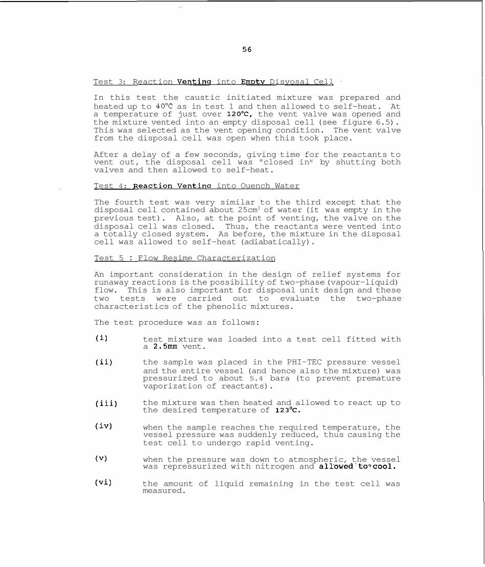
Test 3: Reaction Ventins into Em~tv Disvosal Cell
In this test the caustic initiated mixture was prepared and heated up to 40°C as in test 1 and then allowed to self-heat. At a temperature of just over 120°C, the vent valve was opened and the mixture vented into an empty disposal cell (see figure 6.5). This was selected as the vent opening condition. The vent valve from the disposal cell was open when this took place.
After a delay of a few seconds, giving time for the reactants to vent out, the disposal cell was "closed inN by shutting both valves and then allowed to self-heat.
Test 4: ~eaction Ventina into Ouench Water
The fourth test was very similar to the third except that the disposal cell contained about 25cm3 of water (it was empty in the previous test). Also, at the point of venting, the valve on the disposal cell was closed. Thus, the reactants were vented into a totally closed system. As before, the mixture in the disposal cell was allowed to self-heat (adiabatically).
Test 5 : Flow Resime Characterization
An important consideration in the design of relief systems for runaway reactions is the possibility of two-phase (vapour-liquid) flow. This is also important for disposal unit design and these two tests were carried out to evaluate the two-phase characteristics of the phenolic mixtures.
The test procedure was as follows:
(i) test mixture was loaded into a test cell fitted with a 2.5mm vent.
(ii) the sample was placed in the PHI-TEC pressure vessel and the entire vessel (and hence also the mixture) was pressurized to about 5.4 bara (to prevent premature vaporization of reactants).
(iii) the mixture was then heated and allowed to react up to the desired temperature of 123'~.
(iv) when the sample reaches the required temperature, the vessel pressure was suddenly reduced, thus causing the test cell to undergo rapid venting.
(V) when the pressure was down to atmospheric, the vessel was repressurized with nitrogen and allowed'to~cool.
(vi) the amount of liquid remaining in the test cell was measured.
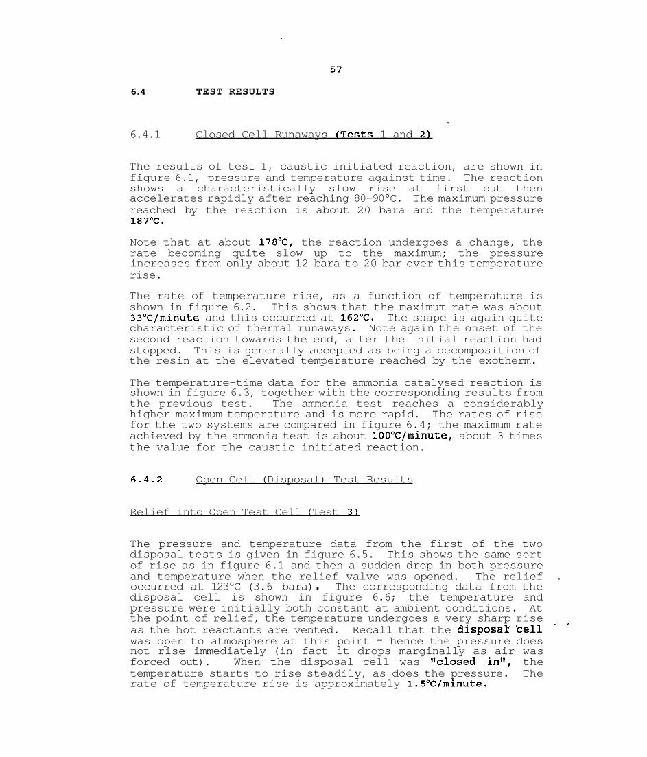
6.4 TEST RESULTS
6.4.1 Closed Cell Runaways (Tests 1 and 2)
The results of test 1, caustic initiated reaction, are shown in figure 6.1, pressure and temperature against time. The reaction shows a characteristically slow rise at first but then accelerates rapidly after reaching 80-90°C. The maximum pressure reached by the reaction is about 20 bara and the temperature 187OC.
Note that at about 17B°C, the reaction undergoes a change, the rate becoming quite slow up to the maximum; the pressure increases from only about 12 bara to 20 bar over this temperature rise.
The rate of temperature rise, as a function of temperature is shown in figure 6.2. This shows that the maximum rate was about 33'C/minute and this occurred at 162'C. The shape is again quite characteristic of thermal runaways. Note again the onset of the second reaction towards the end, after the initial reaction had stopped. This is generally accepted as being a decomposition of the resin at the elevated temperature reached by the exotherm.
The temperature-time data for the ammonia catalysed reaction is shown in figure 6.3, together with the corresponding results from the previous test. The ammonia test reaches a considerably higher maximum temperature and is more rapid. The rates of rise for the two systems are compared in figure 6.4; the maximum rate achieved by the ammonia test is about 10O0C/minute, about 3 times the value for the caustic initiated reaction.
6.4.2 Open Cell (Disposal) Test Results
Relief into Open Test Cell (Test 3)
The pressure and temperature data from the first of the two disposal tests is given in figure 6.5. This shows the same sort of rise as in figure 6.1 and then a sudden drop in both pressure and temperature when the relief valve was opened. The relief . occurred at 123°C (3.6 bara) . The corresponding data from the disposal cell is shown in figure 6.6; the temperature and pressure were initially both constant at ambient conditions. At the point of relief, the temperature undergoes a very sharp rise - , as the hot reactants are vented. Recall that the disposaF'cell was open to atmosphere at this point - hence the pressure does not rise immediately (in fact it drops marginally as air was forced out). When the disposal cell was slclosed in", the temperature starts to rise steadily, as does the pressure. The rate of temperature rise is approximately 1.5"C/minute.
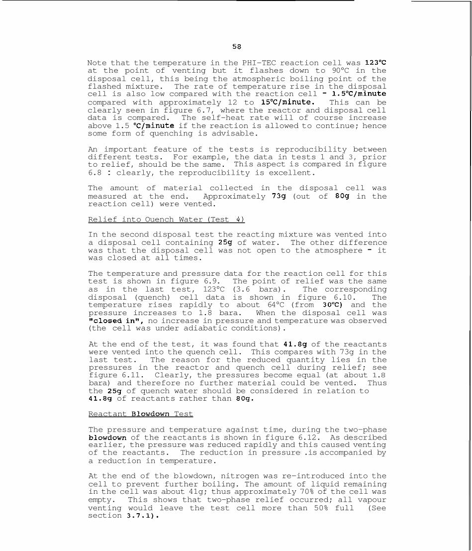
Note that the temperature in the PHI-TEC reaction cell was 123'C at the point of venting but it flashes down to 90°C in the disposal cell, this being the atmospheric boiling point of the flashed mixture. The rate of temperature rise in the disposal cell is also low compared with the reaction cell - 1.5"C/minute compared with approximately 12 to 15'Cfminute. This can be clearly seen in figure 6.7, where the reactor and disposal cell data is compared. The self-heat rate will of course increase above 1.5 OCfminute if the reaction is allowed to continue; hence some form of quenching is advisable.
An important feature of the tests is reproducibility between different tests. For example, the data in tests 1 and 3, prior to relief, should be the same. This aspect is compared in figure 6.8 : clearly, the reproducibility is excellent.
The amount of material collected in the disposal cell was measured at the end. Approximately 739 (out of 809 in the reaction cell) were vented.
Relief into Ouench Water (Test 4 )
In the second disposal test the reacting mixture was vented into a disposal cell containing 259 of water. The other difference was that the disposal cell was not open to the atmosphere - it was closed at all times.
The temperature and pressure data for the reaction cell for this test is shown in figure 6.9. The point of relief was the same as in the last test, 123°C (3.6 bara). The corresponding disposal (quench) cell data is shown in figure 6.10. The temperature rises rapidly to about 64°C (from 30°C) and the pressure increases to 1.8 bara. When the disposal cell was l'closed in", no increase in pressure and temperature was observed (the cell was under adiabatic conditions).
At the end of the test, it was found that 41.8g of the reactants were vented into the quench cell. This compares with 73g in the last test. The reason for the reduced quantity lies in the pressures in the reactor and quench cell during relief; see figure 6.11. Clearly, the pressures become equal (at about 1.8 bara) and therefore no further material could be vented. Thus the 259 of quench water should be considered in relation to 41.89 of reactants rather than 809.
Reactant Blowdown Test
The pressure and temperature against time, during the two-phase blowdown of the reactants is shown in figure 6.12. As described earlier, the pressure was reduced rapidly and this caused venting of the reactants. The reduction in pressure1 .is accompanied by a reduction in temperature.
At the end of the blowdown, nitrogen was re-introduced into the cell to prevent further boiling. The amount of liquid remaining in the cell was about 41g; thus approximately 70% of the cell was empty. This shows that two-phase relief occurred; all vapour venting would leave the test cell more than 50% full (See section 3.7.1) .

However, since the test cell did not completely empty there is some vapour-liquid disengagement hence homogeneous two-phase venting is not observed. (Homogenous two-phase venting would lead to a virtual emptying of the test cell). The so-called "churn-turbulent" two-phase regime is suggested by the results (See Fisher, 1991).
6.5 RELIEF SYSTEM DESIGN BASIS
6.5.1 Im~lications of Test Resu1ts:overview
Before embarking on a detailed analysis of the relief system, in particular the disposal unit, it is useful to review the relevance of the above data since it will provide the basic design information.
The closed cell results, tests 1 and 2, illustrate first and foremost the nature of the problem in that the reaction is capable of reaching pressures of the order of 20 bar (in the case of the NaOH catalysed reaction) or more, and at self-heat rates of 3O0C/minute (or more). Analysis of phenolic reactions show that the pressure closely resembles the vapour pressure of water and that in the event of relief, the mixture will act as a 'tempered' system. That is, the rise in pressure and temperature can be arrested by boiling of reaction mixture provided the relief system is sufficiently large.
The disposal experiments (tests 3 and 4) provide insight into the available options for containment of the vented reactants. The first of these tests (test 3) provides two items of information immediately:
the reaction mixture (present at the relief point) has an atmospheric boiling point of 90°C
the self-heat rate of the flashed reactants is initially 1.5"C/minute.
This information can itself be used to design a simple disposal system as will be described later.
Test 4 provides similarly direct data for a total containment system using water as a quench medium. This shows that reducing the temperature to 60°C (and with the appropriate amount of dilution) provides a safe condition for a total containment drum. Moreover, water is verified as being a suitable quench medium by rapidly cooling the reactants.
The two-phase blowdown experiment (test 5) provides confirmation of the fact that liquid carry-over from the reactor will occur in the event of emergency relief.
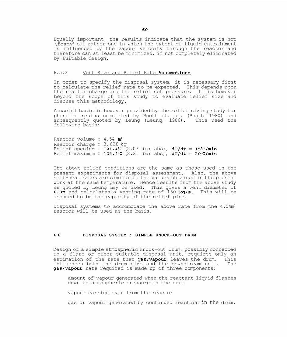
Equally important, the results indicate that the system is not \foamy1 but rather one in which the extent of liquid entrainment is influenced by the vapour velocity through the reactor and therefore can at least be minimized, if not completely eliminated by suitable design.
6.5.2 Vent Size and Relief Rate A S S U ~ D ~ ~ O ~ S
In order to specify the disposal system, it is necessary first to calculate the relief rate to be expected. This depends upon the reactor charge and the relief set pressure. It is however beyond the scope of this study to evaluate relief size and discuss this methodology.
A useful basis is however provided by the relief sizing study for phenolic resins completed by Booth et. al. (Booth 1980) and subsequently quoted by Leung (Leunq, 1986). This used the following basis:
Reactor volume : 4.54 m3 Reactor charge : 3,628 kg Relief opening : 121.4"C (2.07 bar abs), dT/dt = 15'C/min Relief maximum : 123.4'C (2.21 bar abs), dT/dt = 20°C/min
The above relief conditions are the same as those used in the present experiments for disposal assessment. Also, the above self-heat rates are similar to the values obtained in the present work at the same temperature. Hence results from the above study as quoted by Leung may be used. This gives a vent diameter of 0.3m and calculates a venting rate of 150 kg/s. This will be assumed to be the capacity of the relief pipe.
Disposal systems to accommodate the above rate from the 4.54m3 reactor will be used as the basis.
6.6 DISPOSAL SYSTEM : SIMPLE KNOCK-OUT DRUM
Design of a simple atmospheric knock-out drum, possibly connected to a flare or other suitable disposal unit, requires only an estimation of the rate that gas/vapour leaves the drum. This influences both the drum size and the downstream unit. The gas/vapour rate required is made up of three components:
amount of vapour generated when the reactant liquid flashes down to atmospheric pressure in the drum
vapour carried over from the reactor
gas or vapour generated by continued reaction in the drum.
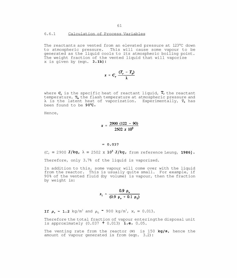
61
6.6.1 Calculation of Process Variables
The reactants are vented from an elevated pressure at 123°C down to atmospheric pressure. This will cause some vapour to be generated as the liquid cools to its atmospheric boiling point. The weight fraction of the vented liquid that will vaporize x is given by (eqn. 3.lb):
where C, is the specific heat of reactant liquid, T, the reactant temperature, T, the flash temperature at atmospheric pressure and h is the latent heat of vaporization. Experimentally, T, has been found to be 90°C.
Hence,
(C, = 2900 J/kg, h = 2502 x lo3 J/kg, from reference Leung, 1986).
Therefore, only 3.7% of the liquid is vaporized.
In addition to this, some vapour will come over with the liquid from the reactor. This is usually quite small. For example, if 90% of the vented fluid (by volume) is vapour, then the fraction by weight is:
kg/m3 and p , - 900 kg/m3, x, = 0.013.
Therefore the total fraction of vapour enteringthe disposal unit is approximately (0.037 + 0.013) i.e. 0.05. The venting rate from the reactor (W) is 150 kg/s, hence the amount of vapour generated is from (eqn. 3.2):

Finally, the vapour produced by continued reaction in the drum must be included. This may be based on the self-heat rate in the drum, found to be 1.5"C/minute experimentally. The amount of vapour produced by this, based on total amount of reactor mass is (eqn 3.3) :
Therefore, the total amount of vapour is:
The density of the vapour at 2.0 bar and 120°C is 1.2 kg/m3 as quoted above (based on Leung, 1986). At 90°C and atmospheric pressure the density p , will become:
= 0.65 kg/m3
Therefore the volumetric flow of vapour is:
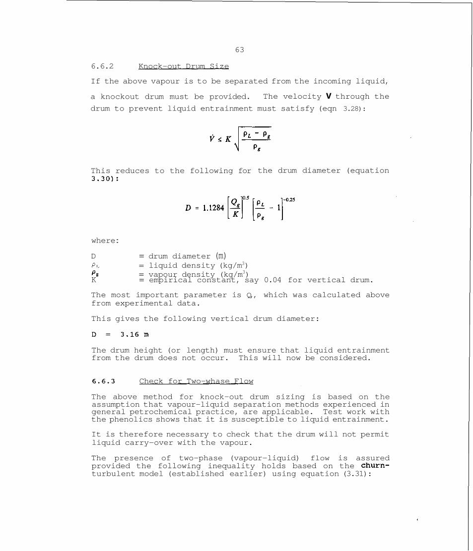
63
6.6.2 Knock-out Drum Size
If the above vapour is to be separated from the incoming liquid,
a knockout drum must be provided. The velocity v through the drum to prevent liquid entrainment must satisfy (eqn 3.28):
This reduces to the following for 3.30):
the drum diameter (equation
where :
D = drum diameter (m) P L = liquid density (kg/m3) P P = vapour density (kg/m3) K = empirical constant, say 0.04 for vertical drum.
The most important parameter is Q,, which was calculated above from experimental data.
This gives the following vertical drum diameter:
The drum height (or length) must ensure that liquid entrainment from the drum does not occur. This will now be considered.
6.6.3 Check for Two-whase Flow
The above method for knock-out drum sizing is based on the assumption that vapour-liquid separation methods experienced in general petrochemical practice, are applicable. Test work with the phenolics shows that it is susceptible to liquid entrainment.
It is therefore necessary to check that the drum will not permit liquid carry-over with the vapour.
The presence of two-phase (vapour-liquid) flow is assured provided the following inequality holds based on the churn- turbulent model (established earlier) using equation (3.31):
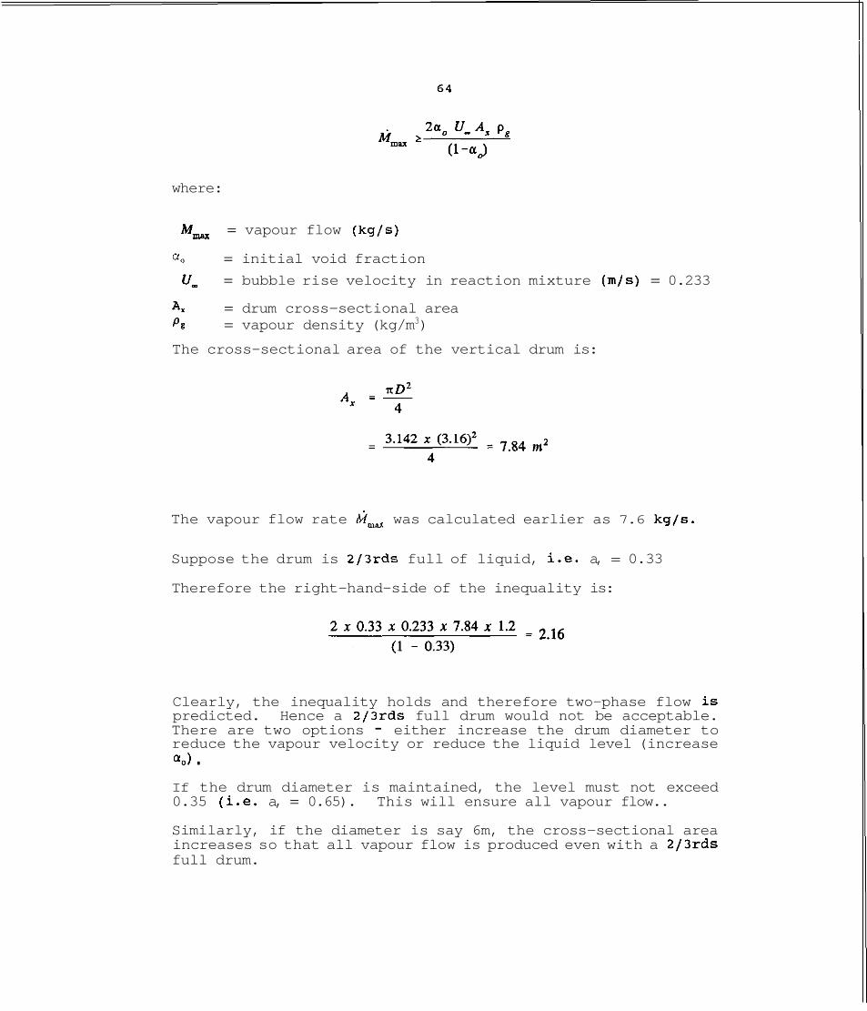
where:
M,, = vapour flow (kg/s)
% = initial void fraction
U_ = bubble rise velocity in reaction mixture (m/s) = 0.233
Ax = drum cross-sectional area PE = vapour density (kg/m3)
The cross-sectional area of the vertical drum is:
The vapour flow rate M- was calculated earlier as 7.6 kg/s.
Suppose the drum is 2/3rds full of liquid, i.e. a, = 0.33
Therefore the right-hand-side of the inequality is:
Clearly, the inequality holds and therefore two-phase flow is predicted. Hence a 2/3rds full drum would not be acceptable. There are two options - either increase the drum diameter to reduce the vapour velocity or reduce the liquid level (increase %) . If the drum diameter is maintained, the level must not exceed 0.35 (i.e. a, = 0.65). This will ensure all vapour flow..
Similarly, if the diameter is say 6m, the cross-sectional area increases so that all vapour flow is produced even with a 2/3rds full drum.
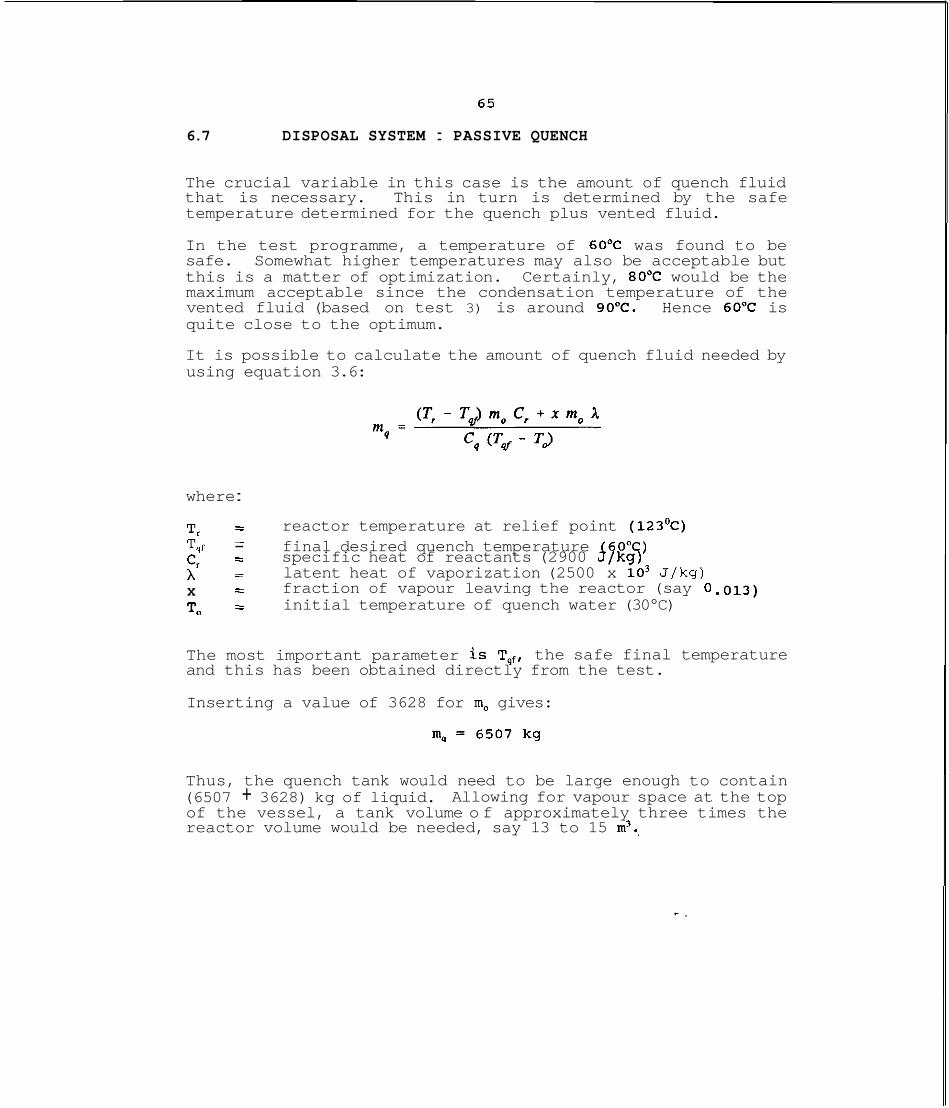
6.7 DISPOSAL SYSTEM : PASSIVE QUENCH
The crucial variable in this case is the amount of quench fluid that is necessary. This in turn is determined by the safe temperature determined for the quench plus vented fluid.
In the test programme, a temperature of 60°C was found to be safe. Somewhat higher temperatures may also be acceptable but this is a matter of optimization. Certainly, 80°C would be the maximum acceptable since the condensation temperature of the vented fluid (based on test 3) is around 90°C. Hence 60°C is quite close to the optimum.
It is possible to calculate the amount of quench fluid needed by using equation 3.6:
where :
T, - - reactor temperature at relief point (123'~) -
T,f - final desired quench temperature (60°C) cr - - specific heat of reactants (2900 J/kg) X - - latent heat of vaporization (2500 x lo3 J/kg) X - - fraction of vapour leaving the reactor (say 0
T o - - initial temperature of quench water (30°C)
The most important parameter is Tqf, the safe final temperature and this has been obtained directly from the test.
Inserting a value of 3628 for m, gives:
Thus, the quench tank would need to be large enough to contain (6507 + 3628) kg of liquid. Allowing for vapour space at the top of the vessel, a tank volume o f approximately three times the reactor volume would be needed, say 13 to 15 m3.,

6.8 CONCLUSIONS
6.8.1 Recommendations for Disposal of Phenolics
Two possible designs for the emergency relief of phenolic reactors have been investigated:
simple knock-out vessel, empty
closed tank containing quench water
The following hypothetical reactor size and venting conditions have been assumed:
Reactor Volume 4.54 m3 Reactor Charge (total) 3628kg Relief opening conditions 121.4'C, 2.07 bara Relief rate 150 kg/S
Based on the experiments completed on a bench-scale calorimeter, the following disposal units have been calculated:
Knock-out Vessel:
Vertical: diameter - 3.16m with volume - 12m3 or, diameter -6m and volume - 6m3
Vessel designed for atmospheric pressure, vent open to atmosphere or to a disposal unit (e.g. flare). Vapour release rate - 7.6 kg/s = 11.7 m3/s.
9uench Drum:
Volume of tank - 13 to 15m3 Volume of quench water - 6.5 m3 Design pressure same as for reactor. Small breather vent to a safe location, to allow for displacement of air. Reactants to be sparged directly into quench water.
6.8.2 Limitations of Results
The disposal system analysis presented in this report is intended only as an example. The details are very specific to the test mixture used and the experimental conditions and do not imply widespread application to phenolic reactions. Particular processes must be evaluated individually.
The most important purpose of the work is to illustrate the manner in which a small calorimeter (PHI-TEC) and similar devices may be used to obtain practical solutions. The test results require careful interpretation but basically, the application is quite simple.
6 . 9 REFERENCES
Booth, A.D., Karmarkar, M., Knight, K. and Potter,
Fisher, H.G. (1991) ,
Leung, J.C., Fauske, H.K. and Fisher, H.G., (1986),
Leung, J.C., (1986),
Trans. Inst. Chem. Eng., 58, 75.
Overview of Emergency Relief System Design Practice, plant/operations Progress (Vol 10, No: 1) January 1991.
Thermochimica Acta 104 (1986) 13-29.
AIChE Journal, October 1986, Vol. 32, No. 10
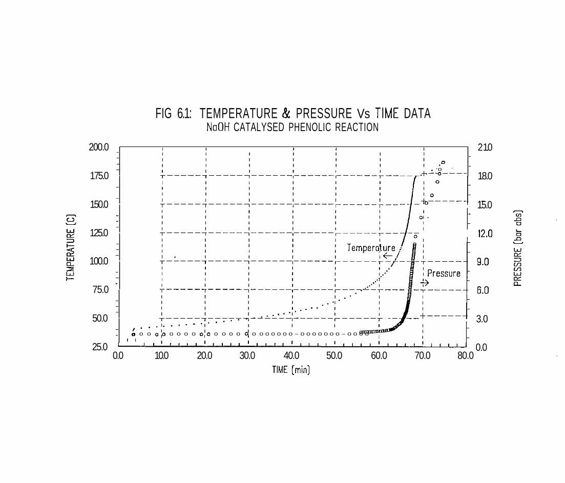
FIG 6.1: TEMPERATURE & PRESSURE Vs TIME DATA NoOH CATALYSED PHENOLIC REACTION
200.0 - I I 4 I I
- I I I I I I I 2 1.0
- -
I I I I I I I I I I I I I I ." I I I I I I . '0 -
- -
175.0 T-----7-----l------,------ .I. l------T-- 7--Q---- 18.0
I - I I I I I I I
- I I I I I I I I T-----7-----1------,------ 150.0 r-----I--- TO------. 15.0 I - I I I I - I I I I - I I I I I I I
-
T-----7-----7------l------ 125.0 r-----T-- 12.0 - I I I I - - I I I I
- I I I I - I I I I I T-----7-----7------l------ 100.0 I - I I I I - I I I I - I I I I I I I
75.0 - - -
T-----7-----l-----1----
I I I I I
- I I I
I I I 4 . . . . I I I . . I .
- T-----777TTT7-'1L-- I - - - - - - - - - - - 50.0 T------. 3.0
I . . . 1 . . . ' . - I I I I
- - I I
0 0 0 o10 0 0 0 0 o 1 0 0 0 0 0 q 0 0 0 0 0 0 0 ~ 0 0 0 0 0 0 0 ~ 0 0 0 0 I I -
25.0 " 1 1 1 1 1 1 1 1 1 1 1 1 1 ~ 1 1 ~ 1 1 1 1 ~ 1 1 , 1 ~ 1 1 1 1 ~ 1 1 1 1 0.0 0.0 10.0 20.0 30.0 40.0 50.0 60.0 70.0 80.0
TIME [rnin]
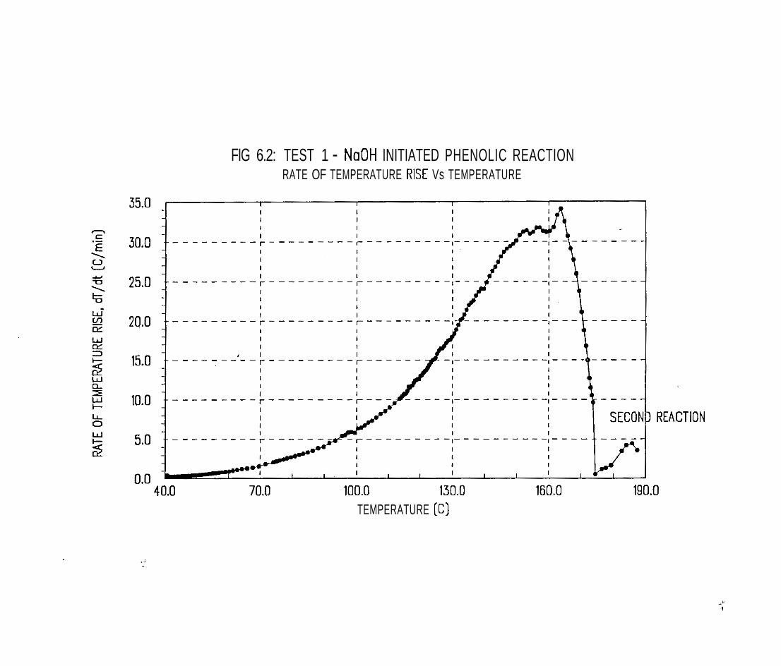
FIG 6.2: TEST 1 - NoOH INITIATED PHENOLIC REACTION RATE OF TEMPERATURE RISE Vs TEMPERATURE
TEMPERATURE ( C )


FIG 6.5: RELIEF OF NaOH INITIATED REACTION PRESSURE & TEMPERATURE Vs TIME IN REACTION CELL
TEST 3 : RELIEF INTO EMPTY TANK
0.0 10.0 20.0 30.0 40.0 50.0 60.0 70.0 TIME [rnin)
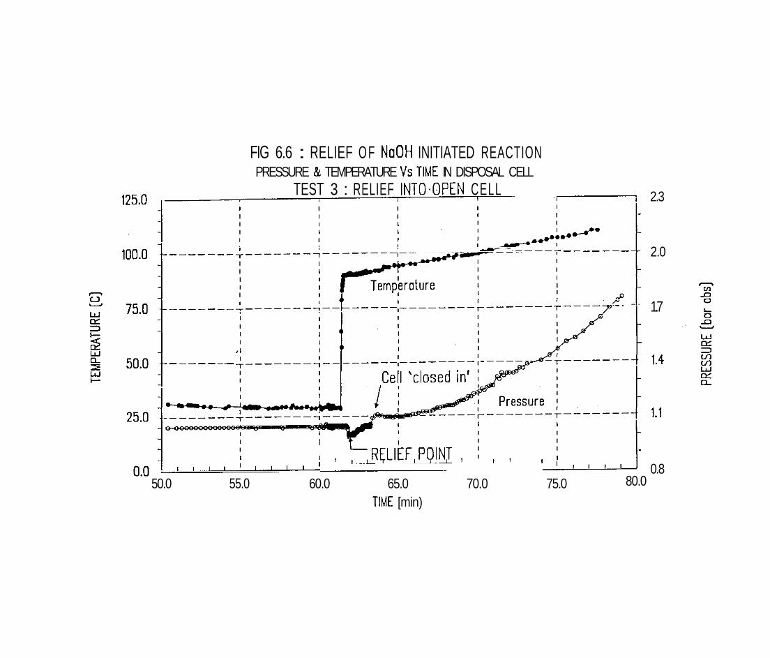
FIG 6.6 : RELIEF O F NoOH INITIATED REACTION PRESSURE & TEMPERATURE Vs TIME IN DISPOSAL CELL
TEST 3 : RELIEF INTO.OPEN CELL I
I 2.3
. I I I I I I I I I -
. I I I I I
. I I I I
-
. - - - - - - - - - - - - - - - - . -
2.0 I -
. I I
I I - I I - - I
. - - - - - - - - -
- - 1.7 I - - I I
- I - - ,I
. - - - - - - - - . I - . I
-
I
I I - I I
- I I I - - I I I , ~ R ~ L I ~ F ~ P ~ I N ~ , I , I I I
1 1 1 1 1 1 1 1 1 1 1 1 1 1 1 0.8
50.0 55.0 60.0 65.0 70.0 75.0 80.0
TIME [min)
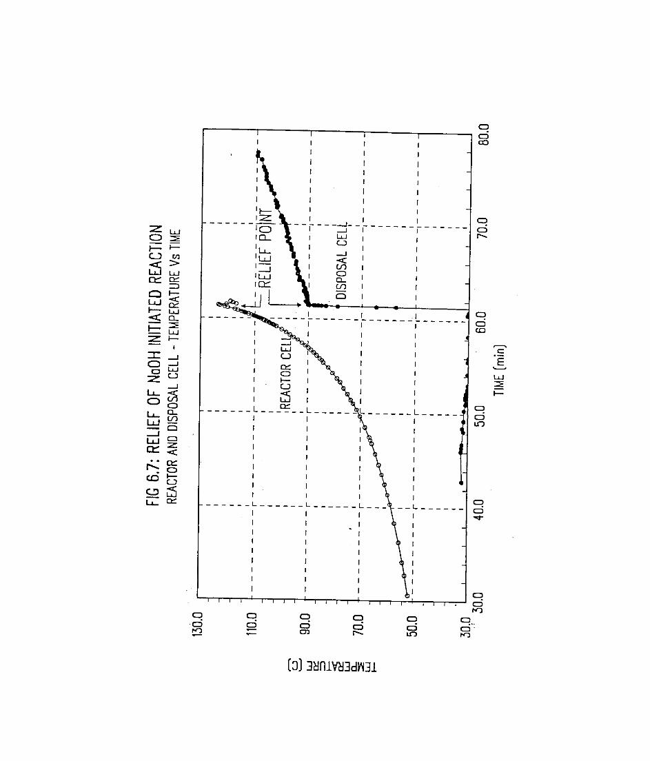

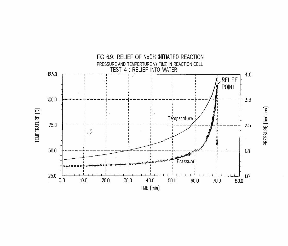
FIG 6.9: RELIEF OF NaOH INITIATED REACTION PRESSURE AND TEMPERTURE Vs TIME IN REACTION CELL
TEST 4 : RELIEF INTO WATER
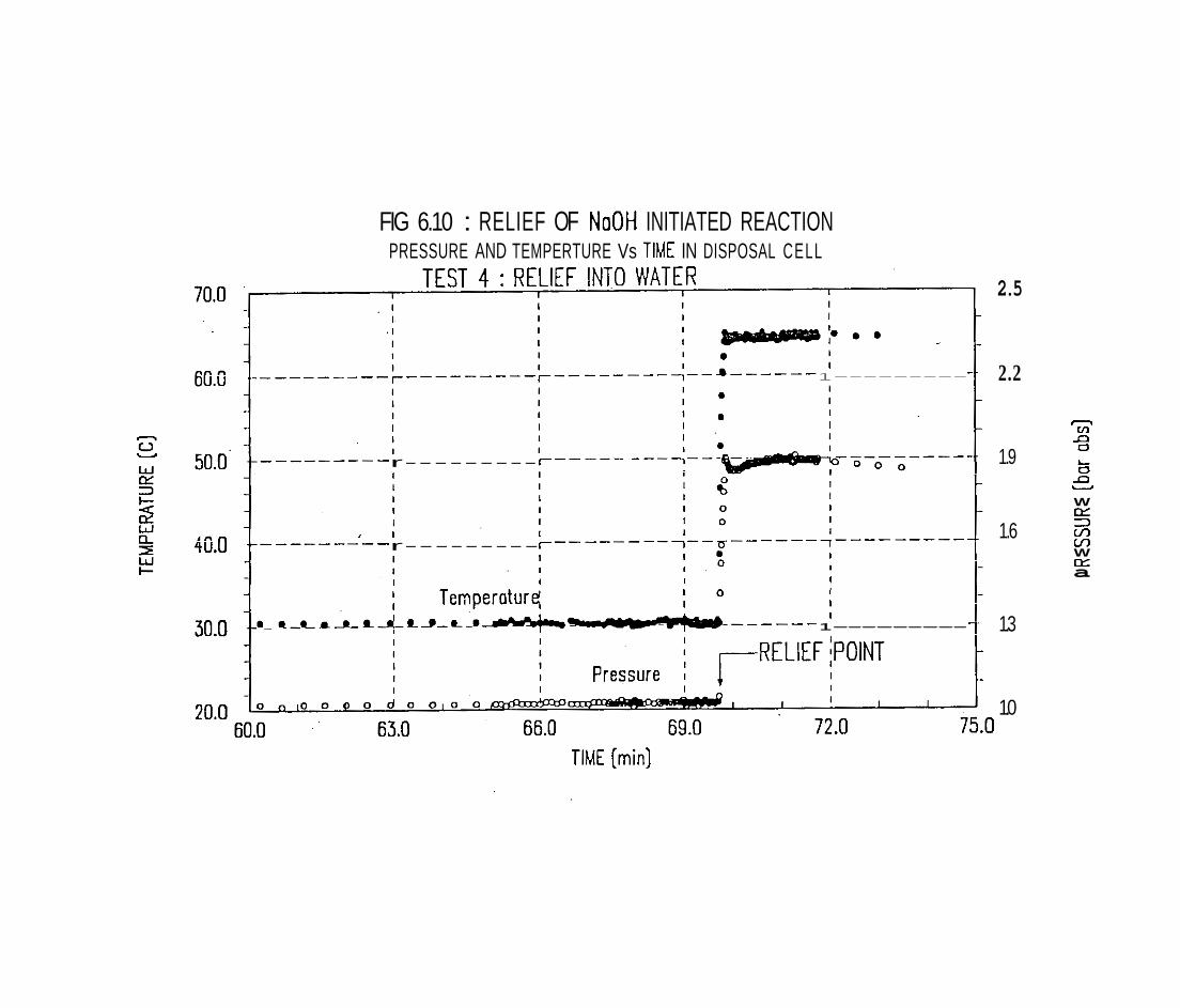
FIG 6.10 : RELIEF OF NoOH INITIATED REACTION PRESSURE AND TEMPERTURE Vs TIME IN DISPOSAL CELL
2.5
1--------- 2.2
C1 V1 n
1.9 0
r--------- L D n U
W r x 3
I I 1.6 m r--------- LI)
W E a
I 0
1--------- 1.3
1.0
TIME [min)
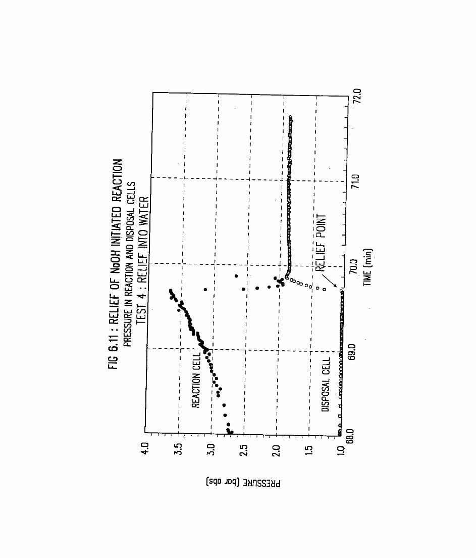
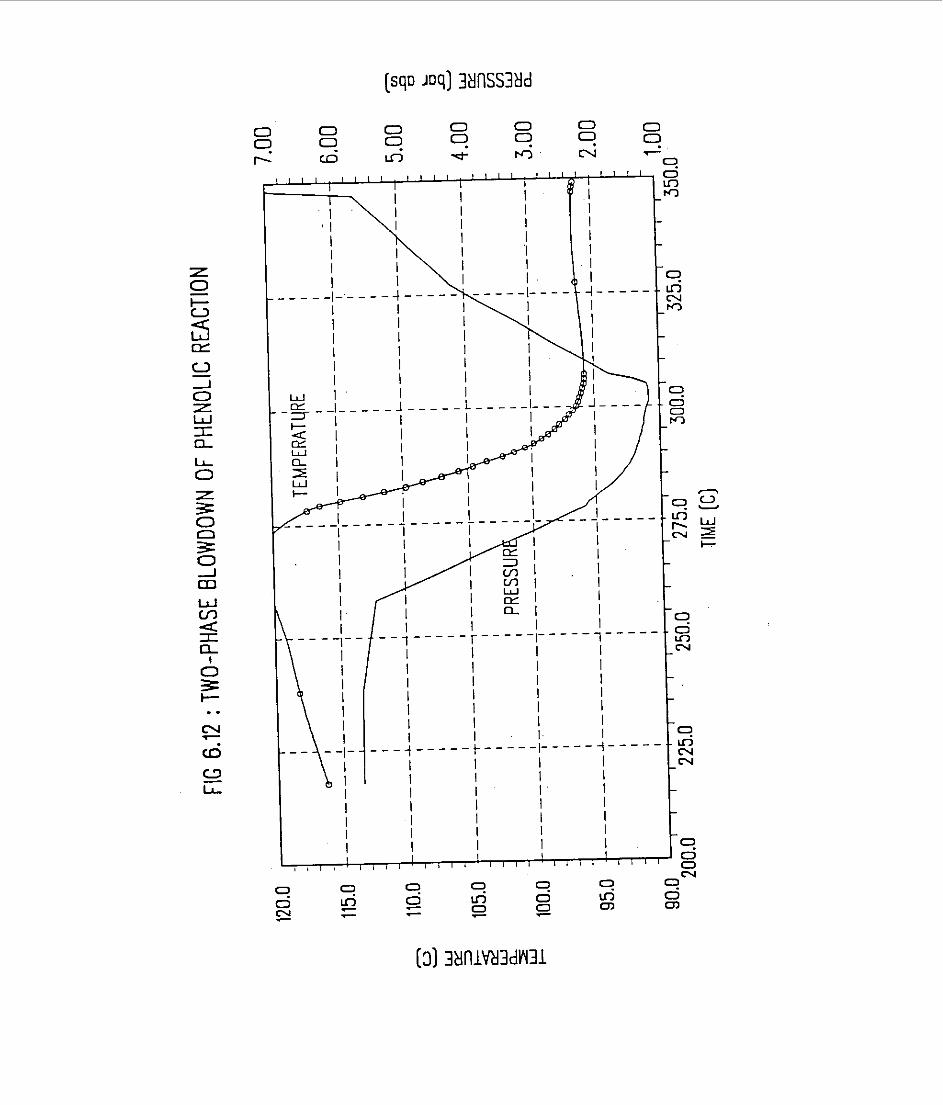

7. EXAMPLE 2 : METHANOL-ACETIC ANHYDRIDE
This is the second example on the design of disposal systems for runaway reactions using bench-scale data. The reaction considered in this case is the exothermic esterification of methanol by acetic anhydride. The reaction is not of major commercial importance but it does have some interesting characteristics, the most important being that the reaction occurs readily at atmospheric temperature. This presents an interesting problem in terms of safe disposal following emergency relief.
The reaction has been studied extensively both as an example for relief sizing (Gibson et. al., 1987, Singh 1989) and for disposal (Singh and Boey, 1990). Therefore the test data can be compared to establish reliability.
7.1 EXPERIMENTAL DETAILS
If there is any reaction in the disposal cell, this can be tracked and quantified.
The test sample was a stoichiometric mixture of methanol and acetic anhydride (molar ratio 2:l). This is the same proportions as that evaluated in ~revious work. The actual quantities used were:
methanol 30.889 acetic anhydride 49.129
TOTAL 80. OOg
The sample was prepared in an ice bath and injected into the test cell. The mixture was heated to 20 - 25OC and then allowed to self-heat.
Two types of tests were carried out - a simple closed cell runaway to. completion and open cell (disposal). tests. The disposal tests were as follows:
venting into an open (atmospheric), empty tekt cell
venting into closed test cells containing different quantities of water.

A total of 4 tests were completed:
Test No. Description
closed cell venting, into empty cell venting into water
In the last 2 tests, the vented fluid was injected directly into the water by extending the vent pipe down to the bottom of the disposal cell.
7 . 2 RESULTS
7.2.1 Closed Cell Test
The methanol-acetic anhydride reaction occurs at ambient temperature - the rise in pressure and temperature against time is shown in figure 7.1.
Characteristically, the reaction commences very.slowly at first but then rises rapidly, reaching a maximum pressure of about 15 bara and a maximum temperature 175OC.
The rate of change of temperature (dT/dt) as a function of temperature from the same data is shown in figure 7.2.
The shapeis typical for a first order reaction; the maximum rate of rise is about 87'C/minute.
7.2.2 Diswosal Tests
Ventina into.Emvtv Cell
The disposal tests were carried out by initiating the venting (from the reaction cell in PHI-TEC) at about 115OC.
In the first test, the disposal cell was empty and initially open to atmosphere. After some reactants have been vented over, the interconnecting valve is closed so that the disposal cell can be studied in isolation. After closing the intervening valve, the valve on the disposal cell itself was closed, allowing the flashed chemicals to react adiabatically. The rise in temperature with time for both the reaction and disposal cells is shown in figure 7.3. The point of venting is clearly marked by a sharp rise in the disposal cell temperature and a fall within the reaction cell. The vented reactants, under adiabatic conditions, show a self-heat rate of 12.5"C/minute. After confirming this rise for a while, the vent valve on the disposal cell was opened, allowing the reactants to boil : a boiling point of about 72'C is clearly shown.

Ventinq into Ouench Water
The first disposal test, discussed above, shows that the reactants cool substantially after venting down to atmospheric pressure but still react at a fairly high rate. Therefore, cooling of the reactants is clearly necessary.
Two tests were carried out to investigate the effect of different quantities of water on the vented reactants. The results were obtained (with M, = mass of water and M, = mass of reactants vented) are given in table 7.1.
TABLE 7.1 : Effect of Quench on Reaction Rate
As the ratio of vented reactants to water is reduced, theinitial mixture temperature becomes lower and the self-heat rate is also reduced. . , .
.. . . <.*% .? The temperature-time trace of the reactor and quench cells for the three tests are shown in figures 7.4 and 7.5. (The detailed test procedure is the same as for the test above). Note that only the initial self-heat rate after venting into disposal tank is important. his is used to determine the acceptability of the quench water quantity.
..,:.. .,~..
Data Consistencv Check
It is important to check that there is consistency in the experimental data between the different tests in order to ensure that differences in results are meaningful. The simplest and most effective check is on the rate of rise within the reaction cell, leading up to the relief point. This data can be compared between all the tests (including the closed test) in terms of dT/dt as a function of temperature.
The composite plot is shown in figure 7.6; clearly excellent reproducibility is indicated.
7.3.1 Review of Test Results
The methanol-acetic anhydride reaction is clearly extremely hazardous, reaching a maximum pressure of about 15 bara and temperature 175'C at a maximum self-heat rate of over 87" C/minute.
Relief of the reaction into an empty, atmospheric disposal tank from an initial temperature of about 115'C would result in a temperature of only 72°C; this confirms the result previously reported (Singh and Boey, 1991). The mixture is still highly reactive at this lower temperature and therefore cooling (quench) of the vented mixture is essential.
The two quench tests provide information on the effectiveness of quenching with water. Using 0.56kg of water per kg of reactants produces a mixture temperature of 63'C and a self-heat rate of 4.O0C/minute. If the dilution is increased to 0.79kg per kg of reactants, then temperature is reduced to 53'C and the self-heat rate is 3. 1°C/minute.
Clearly, even a high degree of dilution does not prevent the mixture from continuing to self-heat. This is to be expected since the reaction occurs at ambient temperature.
7.3.2 Relief Conditions
The disposal rests have been carried out at a reaction temperature of about 115'C. This was selected to coincide with the basis used by Gibson et.al. (Gibson 1987) where the vent sizes needed for a set pressure of about 3.5 bara and different overpressures.
A characteristic of the system is that it vents as a homogeneous two-phase vapour liquid mixture. This was used as the basis for relief sizing in previous studies of this system (Gibson, 1987). For this reason experimental verification has not been carried out.
7.4 DISPOSAL INTO ATMOSPHERIC KNOCK-OUT DRUM
The reactants are vented from an elevated pressure at 115OC down to atmospheric pressure. This will cause some vapour. to be generated as the liquid cools to its atmospheric boiling point. The weight fraction of the vented liquid that will vaporize, X, is given by (eqn. 3. lb) :
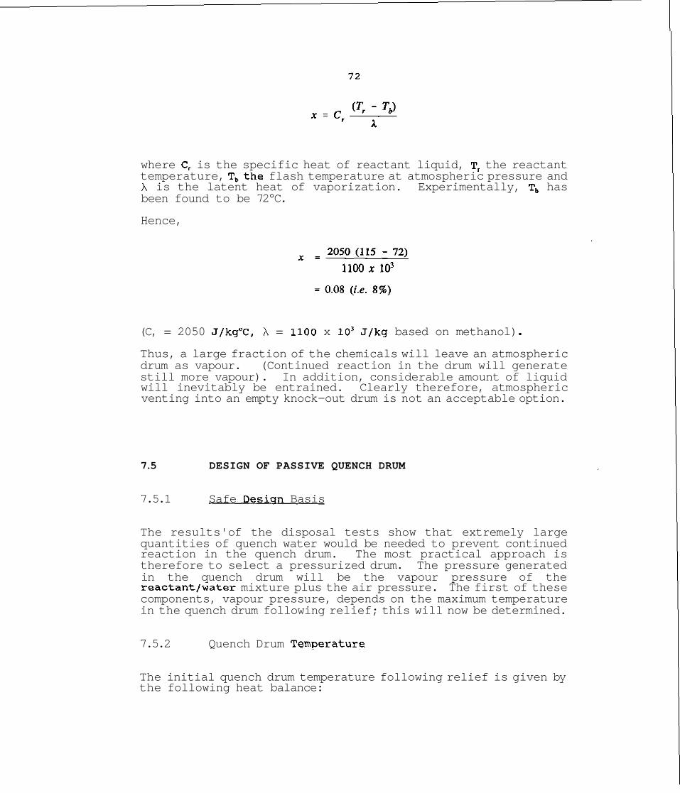
where C, is the specific heat of reactant liquid, T, the reactant temperature, T,the flash temperature at atmospheric pressure and X is the latent heat of vaporization. Experimentally, T, has been found to be 72°C.
Hence,
(C, = 2050 J/kg°C, h = 1100 x lo3 J/kg based on methanol) . Thus, a large fraction of the chemicals will leave an atmospheric drum as vapour. (Continued reaction in the drum will generate still more vapour). In addition, considerable amount of liquid will inevitably be entrained. Clearly therefore, atmospheric venting into an empty knock-out drum is not an acceptable option.
7.5 DESIGN OF PASSIVE QUENCH DRUM
7.5.1 Safe Desiqn Basis
The results' of the disposal tests show that extremely large quantities of quench water would be needed to prevent continued reaction in the quench drum. The most practical approach is therefore to select a pressurized drum. The pressure generated in the quench drum will be the vapour pressure of the reactantlwater mixture plus the air pressure. The first of these components, vapour pressure, depends on the maximum temperature in the quench drum following relief; this will now be determined.
7.5.2 Quench Drum Tern~erature
The initial quench drum temperature following relief is given by the following heat balance:
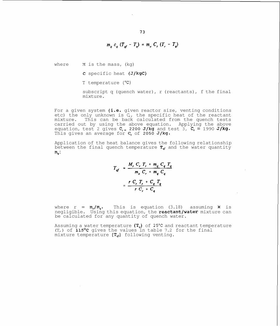
where M is the mass, (kg)
C specific heat (J/kgC)
T temperature (OC)
subscript q (quench water), r (reactants), f the final mixture.
For a given system (i.e. given reactor size, venting conditions etc) the only unknown is C,, the specific heat of the reactant mixture. This can be back calculated from the quench tests carried out by using the above equation. Applying the above equation, test 2 gives C,= 2 2 0 0 J/kg and test 3, C, = 1990 J/kg. This gives an average for C, of 2 0 5 0 J/kg.
Application of the heat balance gives the following relationship between the final quench temperature Tqf and the water quantity m, :
where r = m,/m,. This is equation (3.18) assuming x is negligible. Using this equation, the reactantlwater mixture can be calculated for any quantity of quench water.
Assuming a water temperature (T,) of 25OC and reactant temperature (T,) of 115O~ gives the values in table 7.2 for the final mixture temperature (Tqf) following venting.
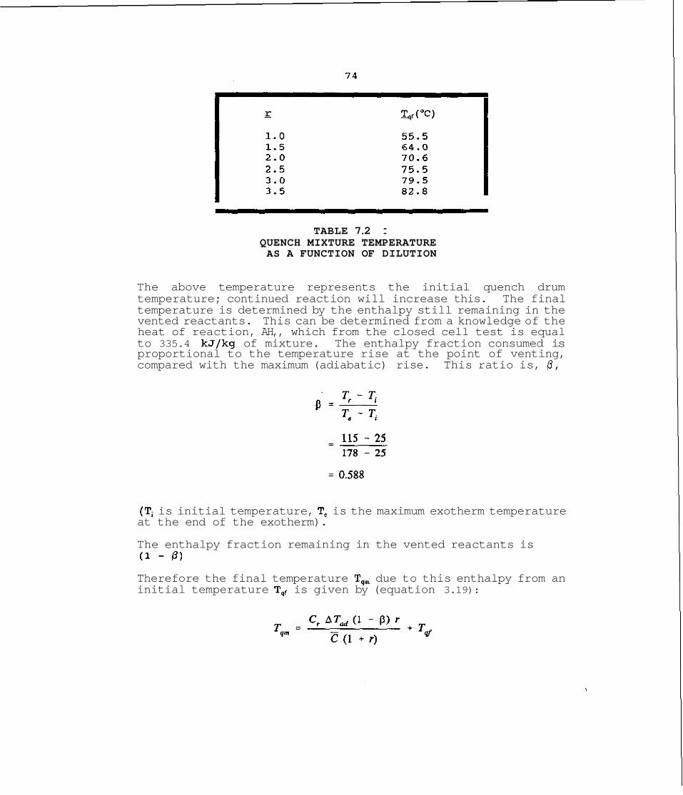
TABLE 7.2 : QUENCH MIXTURE TEMPERATURE AS A FUNCTION OF DILUTION
The above temperature represents the initial quench drum temperature; continued reaction will increase this. The final temperature is determined by the enthalpy still remaining in the vented reactants. This can be determined from a knowledge of the heat of reaction, AH,, which from the closed cell test is equal to 335.4 kJ/kg of mixture. The enthalpy fraction consumed is proportional to the temperature rise at the point of venting, compared with the maximum (adiabatic) rise. This ratio is, 0,
(Ti is initial temperature, T, is the maximum exotherm temperature at the end of the exotherm).
The enthalpy fraction remaining in the vented reactants is (1 - P )
Therefore the final temperature T,, due to this enthalpy from an initial temperature Tqf is given by (equation 3.19):
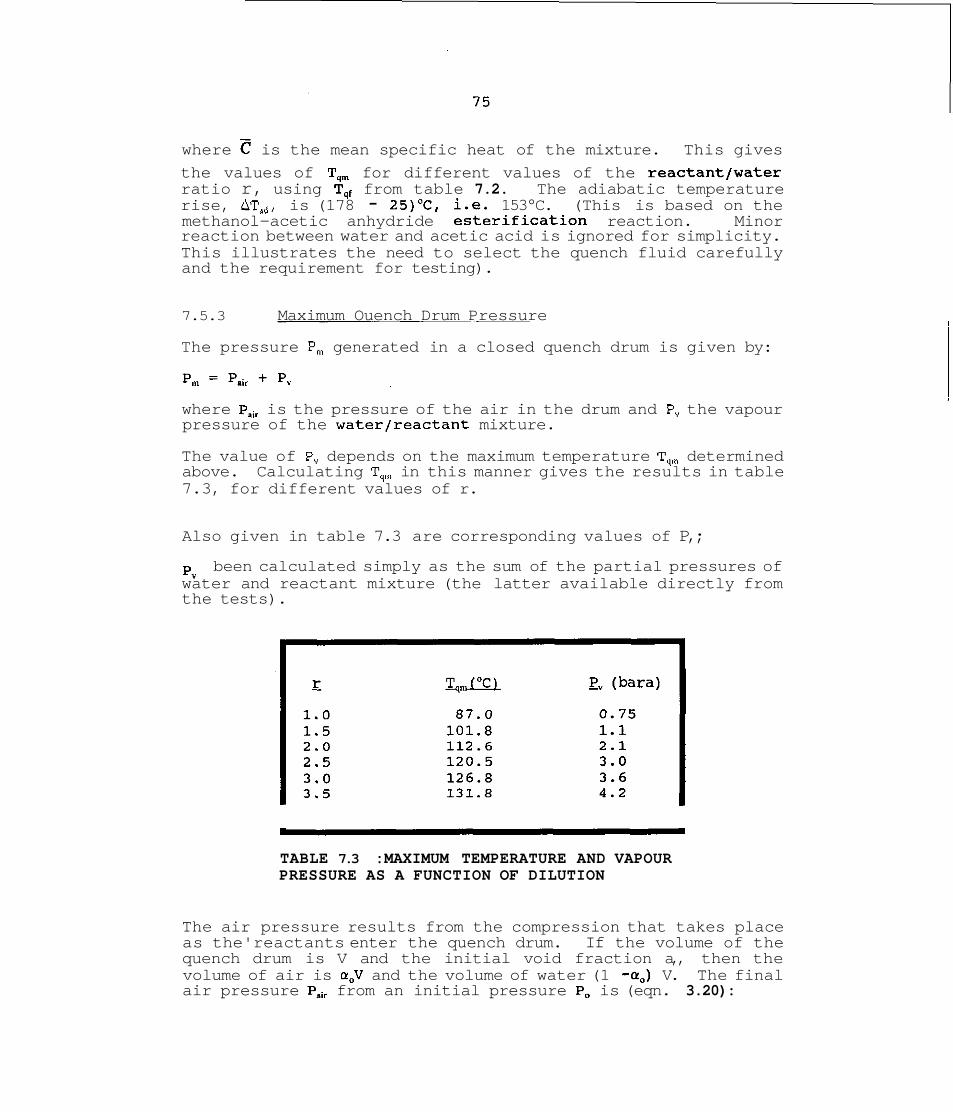
where is the mean specific heat of the mixture. This gives
the values of T,, for different values of the reactantjwater ratio r, using T,, from table 7.2. The adiabatic temperature rise, AT,,, is (178 - 25)'C, i.e. 153°C. (This is based on the methanol-acetic anhydride esterification reaction. Minor reaction between water and acetic acid is ignored for simplicity. This illustrates the need to select the quench fluid carefully and the requirement for testing).
7.5.3 Maximum Ouench Drum Pressure
The pressure P, generated in a closed quench drum is given by:
where Pa,, is the pressure of the air in the drum and P, the vapour pressure of the water/reactant mixture.
The value of P, depends on the maximum temperature T,, determined above. Calculating T,, in this manner gives the results in table 7.3, for different values of r.
Also given in table 7.3 are corresponding values of P,;
P, been calculated simply as the sum of the partial pressures of water and reactant mixture (the latter available directly from the tests).
TABLE 7.3 :MAXIMUM TEMPERATURE AND VAPOUR PRESSURE AS A FUNCTION OF DILUTION
The air pressure results from the compression that takes place as the'reactants enter the quench drum. If the volume of the quench drum is V and the initial void fraction a,, then the volume of air is a,V and the volume of water (1 -a,) V. The final air pressure Pair from an initial pressure Po is (eqn. 3.20):
(where p, = density of water and p , of reactants).
Thus, unlike the vapour pressure component P,, the air pressure also depends on the volume of the drum in relation to the amount of reactants. The air pressure and maximum pressure for different values of r (reactant to water ratio) and a, (initial void fraction in the drum) (assuming p , / p , - 1.25) are given in table 7 . 4 .
TABLE 7.4 : MAXIMUM DISPOSAL DRUM PRESSURE
The last three columns in table 7.4 give the maximum drum pressure (i.e. P,,, + P,,) for a selected set of conditions.
7.6 SELECTION OF QUENCH DRUM DESIGN
7.6.1 Closed System Containment
The previous disposal design study (chapter 6) was based on a hypothetical reactor charge of 3,628 kg; this will also be used as the basis in this case.
Table 7.4 shows that a moderately low pressure disposal drum can be installed in order to quench the methanol-acetic anhydride reaction. The drawback (as will be seen) is that the size of vessel needs to be rather large.
The relief set pressure of the reactor is about 3.5 bara - the disposal drum pressure must be lower than this. In order to minimize the influence of ba'ck-pressure (in the drum) on the venting process, the drum must permit almost uninterrupted relief. This can be achieved by ensuring that the drum pressure is low enough to allow choked flow from the reactor. The pressure ratio needed for this is about 0.9 for flashing two- phase flow; a ratio of say 0.8 would therefore be acceptable. This gives a maximum drum pressure of 2.8 bara.
Looking at table 7.4, this pressure could be satisfied by the following options:
(a) r - 1.25, a, - 0.8 (b) r - 1.7 a, - 0.9
Since the mass of reactants to be vented is 3,628 kg the first option requires a water quantity equal to (362811.25) kg, i.e. 2902 kg, say 3m3 of water. Therefore, the drum volume must be 3/(1-0.8) = 15m3. Similarly for the second option, the water quantity needed is 2134 kg and the drum volume about 21m3. Clearly the first option is to be preferred as it leads to the smallest drum. (Trial and error may produce a more optimal solution) . Therefore, approximately 3000 kg of quench water in a 15m3 drum would be acceptable.
7.6.2 Atmos~heric Pressure Drum
The above considerations apply to a closed disposal drum design. A low pressure drum, open to the atmosphere is feasible provided the maximum temperature in the unit can be kept below the boiling point. This temperature will be between 72 and 100°C depending on the relative amounts of water and reactant : as the water quantity is increased, the boiling point rises but the maximum temperature goes down. From table 7.3, a dilution factor (r) of below 1.5, gives a vapour pressure below 1.1 bar. Hence, r = 1.0 for example (vapour pressure 0.75 bar), would be acceptable. In this case the amount of water required is (3628/1.0)kg, i.e. 3628 kg, say a drum volume of 10m3 allowing for some void. This is considerably less than the 15m3 for a closed drum.
The open drum design will not of course totally contain the organic vapours. The air in the drum will be displaced and may be assumed to be saturated with the vented chemicals. This may be acceptable in many instances particularly if the air line can be taken to a safe location.
CONCLUSIONS
The methanol-acetic anhydride reaction presents an interesting disposal problem due to the fact that is very difficult to prevent continued reaction, even after quenching. This means that the design must allow for the fact that the reaction will continue in the disposal vessel.
The basis used for the design is a reactor charge of 3628 kg, released at a temperature of about 115°C.
Two disposal options have been considered:
(a) Total Containment
Quench drum volume : 15m3 Quench water : 3m3 Maximum drum pressure : 2.8 bara
(b) Atmospheric (Open) Drum
Quench drum volume : i0m3 Quench water : 3.6m3
Maximum drum pressure : atmospheric
The second option will allow air, saturated with organics to be released into the atmosphere.
Relief directly into an atmospheric knock-out drum without quenching is not appropriate for this system. It is likely that the vented chemicals will boil-over out of such a tank. Also, reaction will continue in an atmospheric tank without dilution.
IMPORTANT NOTE
It is important that, if the quench fluid is not inert to the vented liquid, then due account is taken of any reaction between the quench fluid and the vented material. In this particular example, unreacted acetic anhydride may react with water. Any such reaction is of course evident from the test; nevertheless a suitable choice of quench liquid is important and water will not always be appropriate.
REFERENCES
Gibson, N., Madison, N and Rogers R.L. (1987)
Singh, J. (1989)
Singh, J. and Boey, D. (1991),
Hazards From Pressure : Exothermic Reactions, Unstable Substances, Pressure Relief and Accidental Discharge, IChemE Symposium Series No: 102, UMIST, 16-18 June 1987
International Symposium on Runaway Reactions, March 7-9 1989 Cambridge, Mass
Plant Operations Progress, Vol. 10, No: 1, January 1991
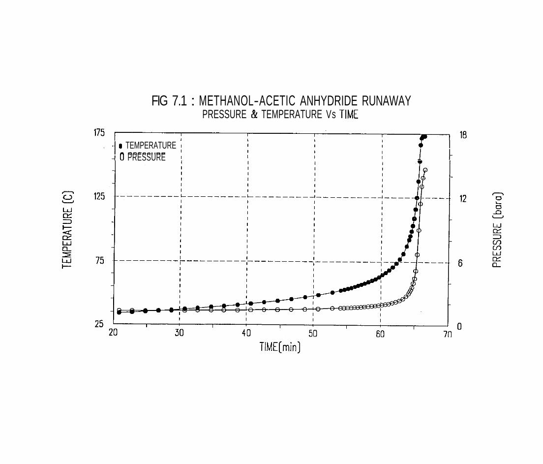
FIG 7.1 : METHANOL-ACETIC ANHYDRIDE RUNAWAY PRESSURE & TEMPERATURE Vs TIME
a TEMPERATURE I
0 PRESSURE I
TIME[min]

FIG 7.2 : METHANOL-ACETIC ANHY DRlDE REACTION RATE OF TEMPERATURE RISE Vs TEMPERATURE


FIG 7.4 : RELIEF INTO QUENCH WATER [TEST 3) TEMPERATURE Vs TlME
TIME (min)
RISE IN
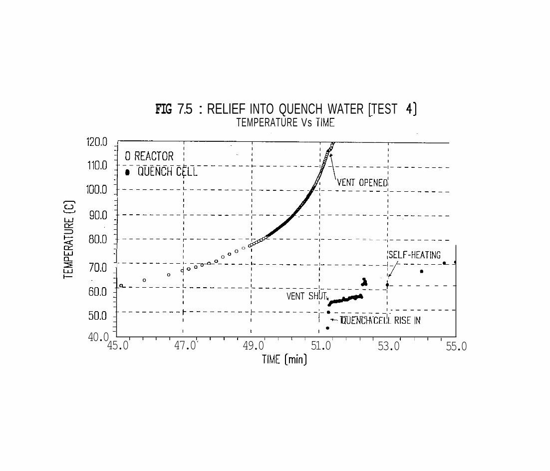
FIG 7.5 : RELIEF INTO QUENCH WATER [TEST 41 - 7
TEMPERATURE Vs TIME
TIME [min]
-
-
70.0 : - -
&o - - - -
50.0 - - -
40.0 -
I o O 1 I
I 0 O 1 I I F F - H E A T I N G I .--&o - - - - - L - - - - - - - - - I - - - - - - - - - - I- - - - - - - L A {0° I I
0 I I I 0 I I I
I I :o - - - - - - - - - - - - - - - - - - - - - - 1 - - + - - - - - - - - I I I I I I I I
VENT SH~T+/ I I
- - - - - - - - I I I r - - - - - - - - - r - - - - - - - - - I-. - - - - - - - - - - - - - - - - - - I I
I I I I
I I - - I E M P E M T ~ ~ QUENCH CECL RISE IN I
I I I I I I I I I I 1 I I I
45.0 47.0 ' 49.0 I 1 I I I
51.0 53.0 I
55.0
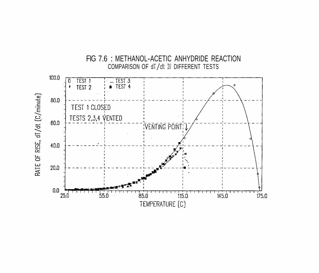
FIG 7.6 : METHANOL-ACETIC ANHYDRIDE REACTION COMPARISON OF dT/dt IN DIFFERENT TESTS
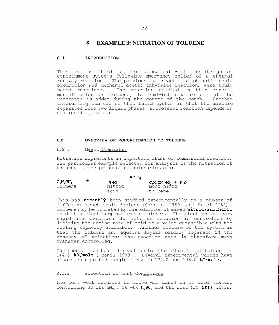
8. EXAMPLE 3: NITRATION OF TOLUENE
8.1 INTRODUCTION
This is the third reaction concerned with the design of containment systems following emergency relief of a thermal runaway reaction. The previous two reactions, phenolic resin production and methanol-acetic anhydride reaction, were truly batch reactions. The reaction studied in this report, mononitration of toluene, is semi-batch where one of the reactants is added during the course of the batch. Another interesting feature of this third system is that the mixture separates into two liquid phases; successful reaction depends on continued agitation.
8.2 OVERVIEW OF MONONITRATION OF TOLUENE
8.2.1 Basic Chemistry
Nitration represents an important class of commercial reaction. The particular example selected for analysis is the nitration of toluene in the presence of sulphuric acid:
+ C6HsCH, HNO, -t C6H4CH3N02 + H,O Toluene Nitric mono-nitro
acid toluene
This has rec,ently been studied experimentally on a number of different bench-scale devices (Cronin, 1989, and Steel 1989). Toluene may be nitrated by the addition of mixed nitric/sulphuric acid at ambient temperatures or higher. The kinetics are very rapid and- therefore the rate of reaction is controlled by limiting the dosing rate of acid to a value compatible with the cooling capacity available. Another feature of the system is that the toluene and aqueous layers readily separate in the absence of agitation; the reaction rate is therefore mass transfer controlled.
The theoretical heat of reaction for the nitration of toluene is 144.8 kJ/mole (Cronin 1989). Several experimental values have also been reported ranging between 135.2 and 148.0 kJ/mole.
8.2.2 Selection of test Conditions
The test work referred to above was based on an acid mixture containing 30 wt% HNO,, 56 wt% H,S04 and the rest (14 wt%) water.

Reaction stoichiometry shows that lg of toluene requires 2.279 of "mixed acidsn for complete conversion.
In a commercial process, the acids would be added for a period of time, say a couple of hours, the actual rate being determined by the available cooling capacity. From a business view, the shortest batch time will be preferred.
An operating fault leading to emergency relief could arise under a number of situations. A common cause is cooling supply failure while the acid feed is continued. Another potentially more serious situation is loss of agitation, leading to accumulation of unreacted acid; then, when agitation is restored a rapid exotherm will result.
~diabatic'ex~eriments can simulate such incidents by injecting a prescribed amount of acid into hot toluene, while maintaining agitation. The amount of acid, relative to the toluene, must in practice be based on a hazard study of the process; a value of between 10 and 15% of the total batch quantity is not an unreasonable choice. If the batch period were 2 hours for example, this would imply accumulation for 12 to 18 minutes. This is a reasonable basis for the tests and will be used to investigate disposal system design.
8.3 EXPERIMENTAL DETAILS
Test Mixtures Studied
One test was carried out with the following mixture:
Toluene 509 Mixed acids 109
This was the first mixture studied and represents a relatively mild exotherm.
The main set of experiments were performed using the following mixture:
Toluene 509 Mixed acids 159
- 654

Mixed acids consisted of:
HNO, 30% (wt) H2S04 56% (wt) Hz0 14% (wt)
The 159 of mixed acids represents 13.2% of the acid required for a total batch.
Closed Cell Tests
Two tests were carried out in which an exothermic reaction was induced by injecting cold acids to preheated toluene. The resulting reaction was allowed to go to completion.
Test 1
Toluene (50g) at 80°C, with log of acids injected.
Test 2
Toluene (509) at 6O0C, with 159 of acids injected.
In each case the test cell was first evacuated and purged with N,. The toluene was then heated to the required temperature and then the acids syringed directly as a single shot.
Ouen Cell Tests
Three venting tests were carried out in which the reaction was initiated in the same manner as test 2 above (i.e. at 60°C) and vented into a disposal cell at about 115'C. The three tests were as follows:
Tests 3 and 4
Reactants vented into an empty disposal cell at atmospheric pressure. The disposal cell was isolated and 'closed in1 immediately after venting to allow the flash cooled reactants to react adiabatically. The two tests were intended to be identical.
Test 5
In this case the disposal cell contained some quench water prior to venting. In all other respects, the procedure was the same as in tests 3 and 4.
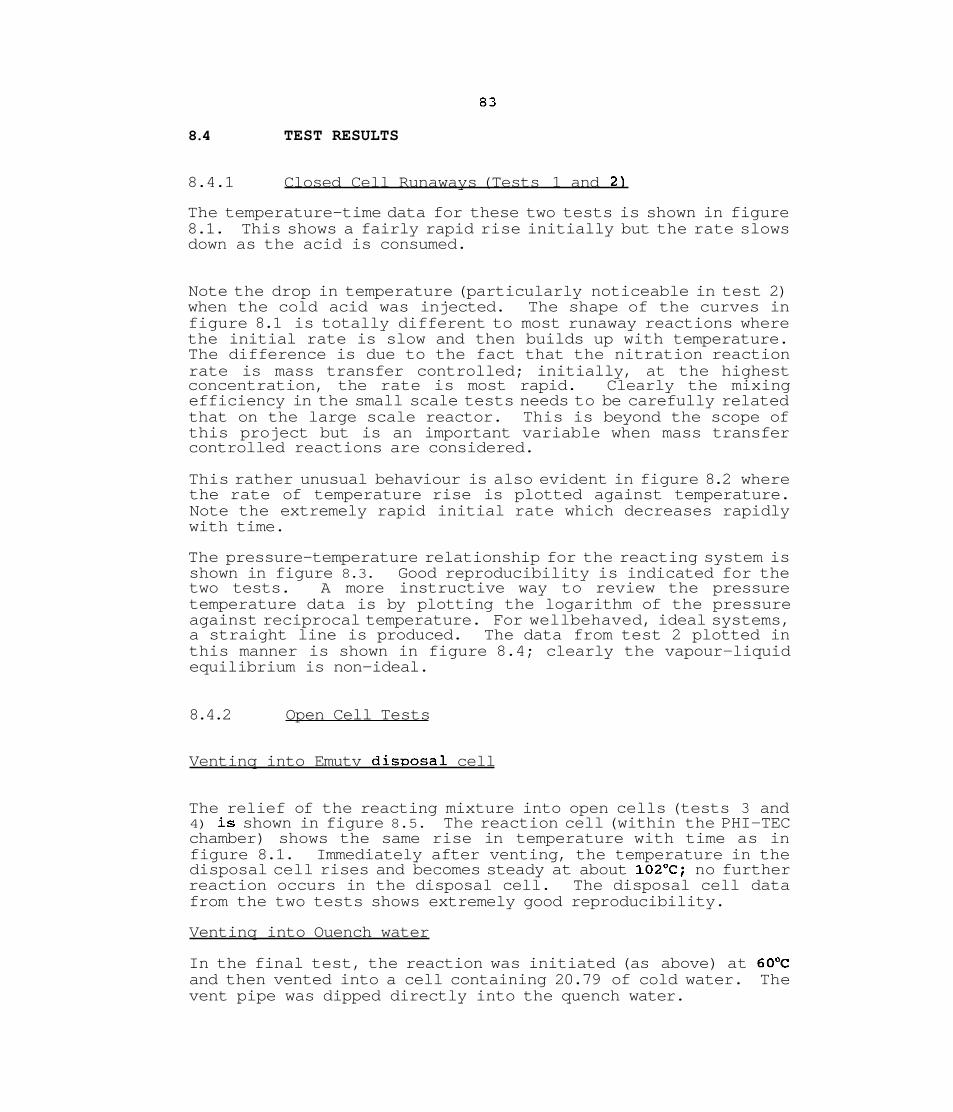
8.4 TEST RESULTS
8.4.1 Closed Cell Runaways (Tests 1 and 2)
The temperature-time data for these two tests is shown in figure 8.1. This shows a fairly rapid rise initially but the rate slows down as the acid is consumed.
Note the drop in temperature (particularly noticeable in test 2) when the cold acid was injected. The shape of the curves in figure 8.1 is totally different to most runaway reactions where the initial rate is slow and then builds up with temperature. The difference is due to the fact that the nitration reaction rate is mass transfer controlled; initially, at the highest concentration, the rate is most rapid. Clearly the mixing efficiency in the small scale tests needs to be carefully related that on the large scale reactor. This is beyond the scope of this project but is an important variable when mass transfer controlled reactions are considered.
This rather unusual behaviour is also evident in figure 8.2 where the rate of temperature rise is plotted against temperature. Note the extremely rapid initial rate which decreases rapidly with time.
The pressure-temperature relationship for the reacting system is shown in figure 8.3. Good reproducibility is indicated for the two tests. A more instructive way to review the pressure temperature data is by plotting the logarithm of the pressure against reciprocal temperature. For wellbehaved, ideal systems, a straight line is produced. The data from test 2 plotted in this manner is shown in figure 8.4; clearly the vapour-liquid equilibrium is non-ideal.
8.4.2 Open Cell Tests
Ventinq into Emutv disuosal cell
The relief of the reacting mixture into open cells (tests 3 and 4) is shown in figure 8.5. The reaction cell (within the PHI-TEC chamber) shows the same rise in temperature with time as in figure 8.1. Immediately after venting, the temperature in the disposal cell rises and becomes steady at about 102'C; no further reaction occurs in the disposal cell. The disposal cell data from the two tests shows extremely good reproducibility.
Ventinq into Ouench water
In the final test, the reaction was initiated (as above) at 60°C and then vented into a cell containing 20.79 of cold water. The vent pipe was dipped directly into the quench water.
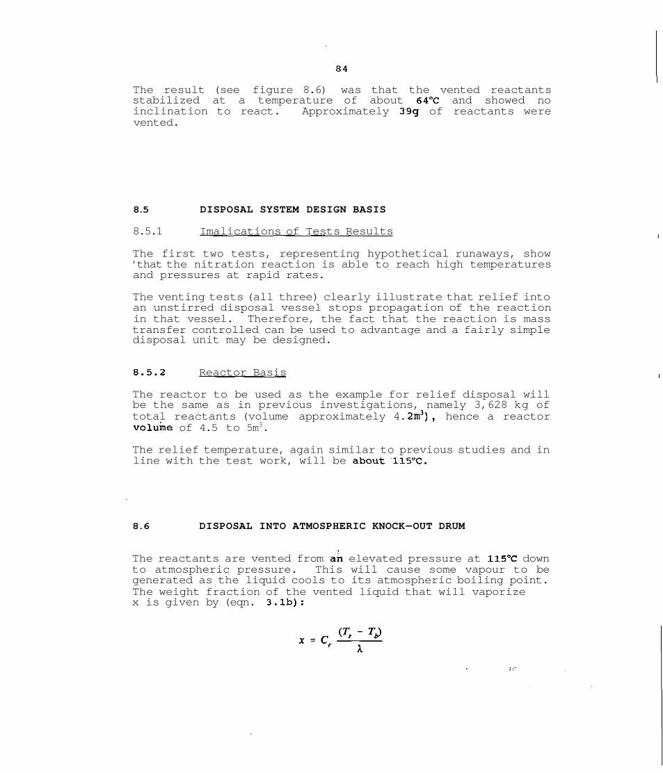
The result (see figure 8.6) was that the vented reactants stabilized at a temperature of about 64OC and showed no inclination to react. Approximately 399 of reactants were vented.
8.5 DISPOSAL SYSTEM DESIGN BASIS
8.5.1 Imalications of Tests Results
The first two tests, representing hypothetical runaways, show 'that the nitration reaction is able to reach high temperatures and pressures at rapid rates.
The venting tests (all three) clearly illustrate that relief into an unstirred disposal vessel stops propagation of the reaction in that vessel. Therefore, the fact that the reaction is mass transfer controlled can be used to advantage and a fairly simple disposal unit may be designed.
8.5.2 Reactor Basis
The reactor to be used as the example for relief disposal will be the same as in previous investigations, namely 3,628 kg of total reactants (volume approximately 4. 2m3) , hence a reactor voluine of 4.5 to 5m3.
The relief temperature, again similar to previous studies and in line with the test work, will be aboutll5"C.
8.6 DISPOSAL INTO ATMOSPHERIC KNOCK-OUT DRUM
The reactants are vented from a; elevated pressure at 115'C down to atmospheric pressure. This will cause some vapour to be generated as the liquid cools to its atmospheric boiling point. The weight fraction of the vented liquid that will vaporize x is given by (eqn. 3.lb):
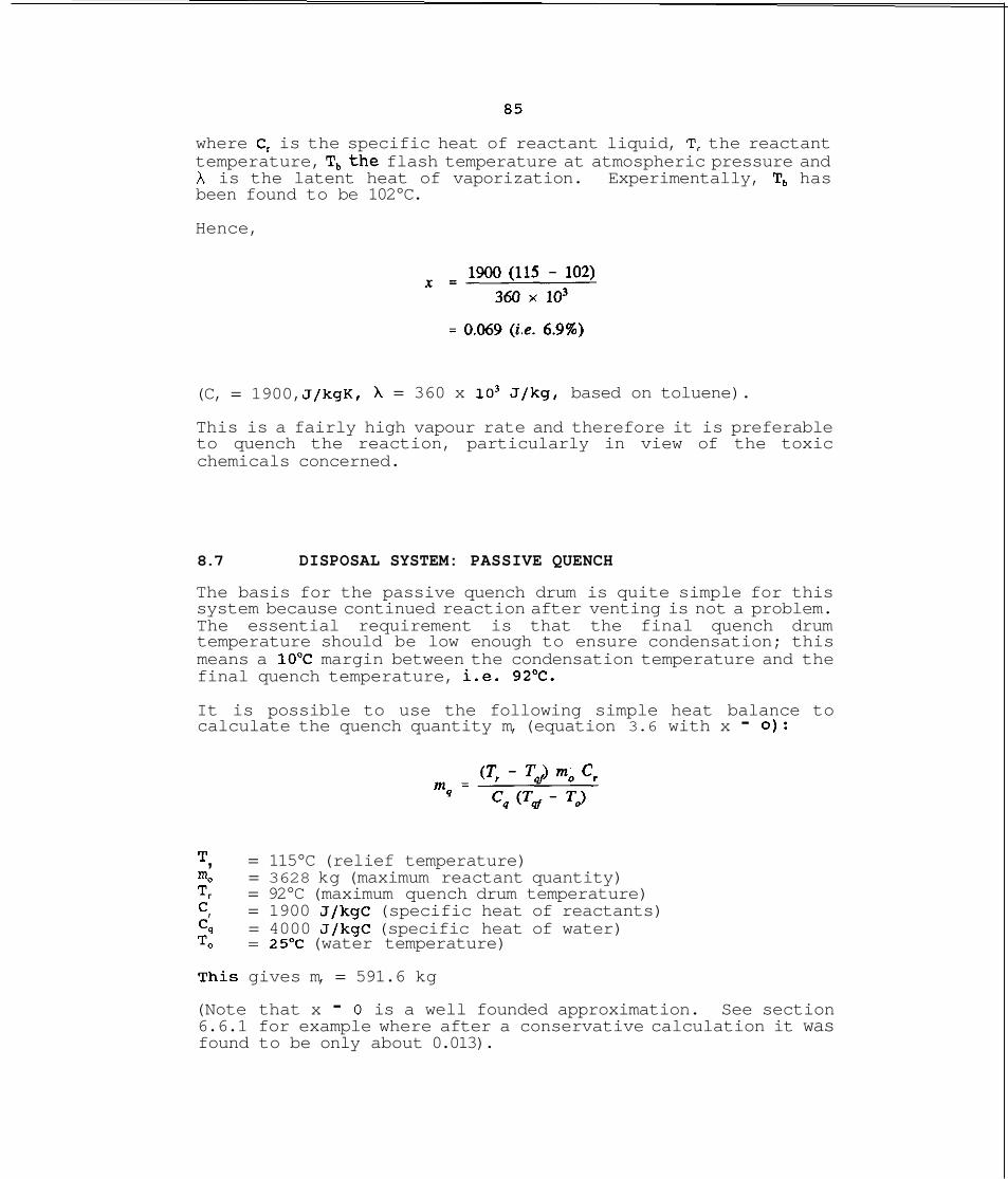
where C, is the specific heat of reactant liquid, T, the reactant temperature, T,the flash temperature at atmospheric pressure and h is the latent heat of vaporization. Experimentally, T, has been found to be 102°C.
Hence,
(C, = 1900, J/kgK, = 360 x lo3 J/kg, based on toluene).
This is a fairly high vapour rate and therefore it is preferable to quench the reaction, particularly in view of the toxic chemicals concerned.
8.7 DISPOSAL SYSTEM: PASSIVE QUENCH
The basis for the passive quench drum is quite simple for this system because continued reaction after venting is not a problem. The essential requirement is that the final quench drum temperature should be low enough to ensure condensation; this means a 10DC margin between the condensation temperature and the final quench temperature, i.e. 92OC.
It is possible to use the following simple heat balance to calculate the quench quantity m, (equation 3.6 with x - 0):
T , = 115°C (relief temperature) no = 3628 kg (maximum reactant quantity) T, = 92°C (maximum quench drum temperature) C , = 1900 J/kgC (specific heat of reactants) C, = 4000 J/kgC (specific heat of water) To = 25OC (water temperature)
his gives m, = 591.6 kg
(Note that x - 0 is a well founded approximation. See section 6.6.1 for example where after a conservative calculation it was found to be only about 0.013).
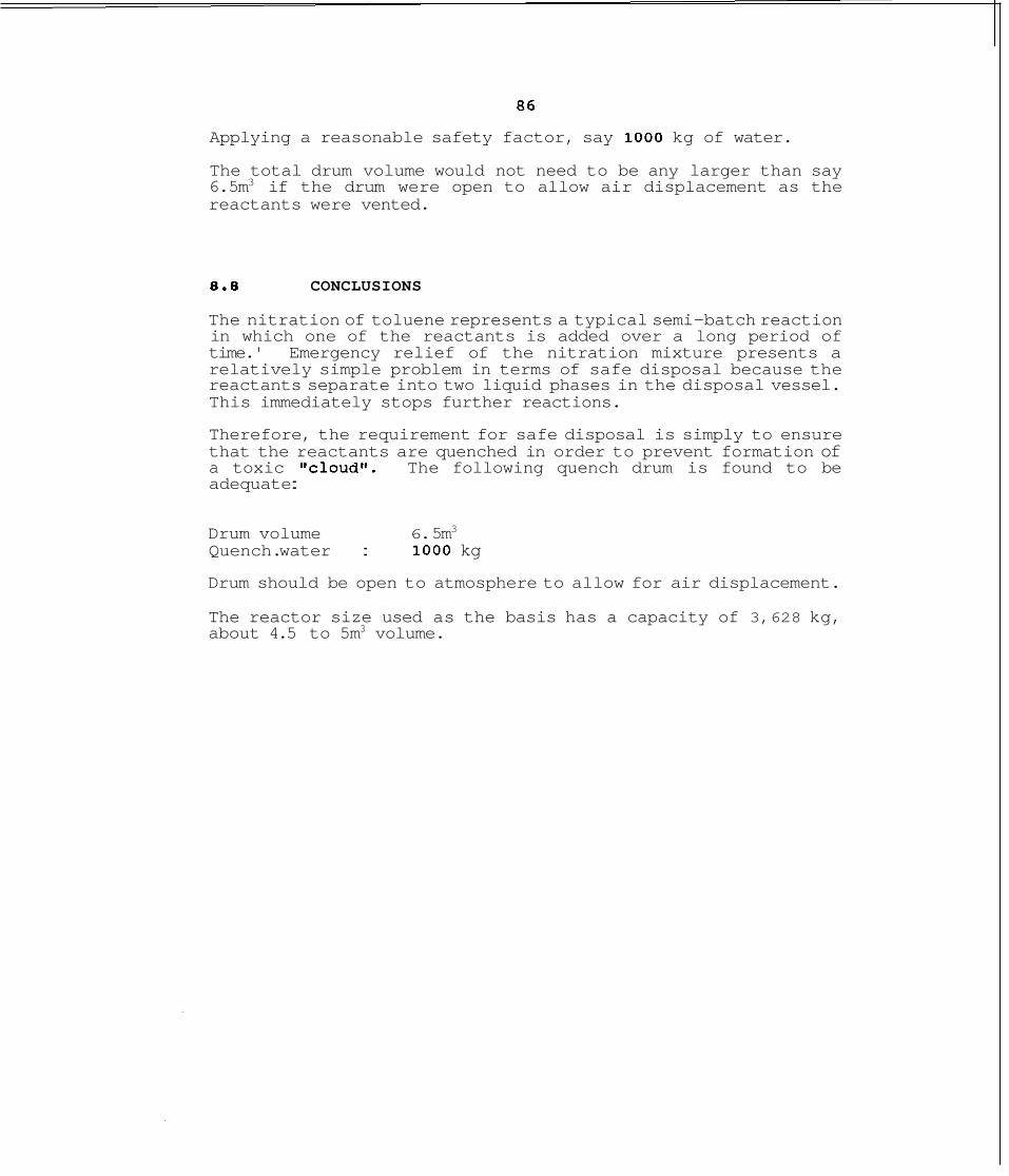
Applying a reasonable safety factor, say 1000 kg of water.
The total drum volume would not need to be any larger than say 6.5m3 if the drum were open to allow air displacement as the reactants were vented.
8 .8 CONCLUSIONS
The nitration of toluene represents a typical semi-batch reaction in which one of the reactants is added over a long period of time.' Emergency relief of the nitration mixture presents a relatively simple problem in terms of safe disposal because the reactants separate into two liquid phases in the disposal vessel. This immediately stops further reactions.
Therefore, the requirement for safe disposal is simply to ensure that the reactants are quenched in order to prevent formation of a toxic cloud^^. The following quench drum is found to be adequate :
Drum volume 6. 5m3
Quench. water : 1000 kg
Drum should be open to atmosphere to allow for air displacement.
The reactor size used as the basis has a capacity of 3,628 kg, about 4.5 to 5m3 volume.
8.9 REFERENCES
Cronin, J.L., Nolan, P.F., and Barton, J.A., (1989)
Steele, C.H. and Nolan, P.F., (1989) ,
International Symposium on Runaway Reactions, March 7- 9, 1989, Cambridge, Mass.
ibid.

FIG 8.1 : NITRATION OF TOLUENE CLOSED C E L L RUNAWAY TEMPERATURE Vs TlME
TlME [min]

FIG 8.2 : NITRATION OF TOLUENE CLOSED C E L L RUNAWAY . . - - . - .
RATE OF TEMPERATURE RISE Vs TEMPERATURE

FIG 8.3 : NITRATION OF TOLUENE RUNAWAY REACTION PRESSURE Vs TEMPERATURE
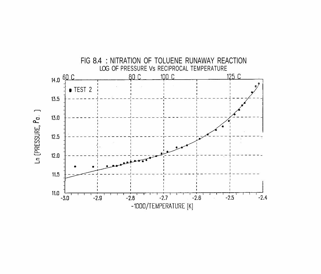
FIG 8.4 : NITRATION OF TOLUENE RUNAWAY REACTION LOG OF PRESSURE Vs RECIPROCAL TEMPERATURE
I
I TEST 2 I I
-1000/TEMPERATURE [K]


FIG 8.6 :NITRATION OF TOLUENE - VENTING INTO WATER TEMPERATURE Vs TIME
9. EXAMPLE 4 : H,O, DECOMPOSITION
9.1 INTRODUCTION
This is the fourth chemical system to be studied for the design of containment systems following relief of a runaway reaction. The first three systems, phenolic resin reaction, methanol-acetic anhydride runaway and nitration of toluene, were reactions which could be quenched with a cold solvent. The reactants and products in these systems were condensible at reasonable temperatures.
The final system to be considered in this report is a thermal runaway which generates non-condensible gas (oxygen). Therefore, safe disposal of the reactants will present different problems to those for previous systems. As for all the examples presented, it is important that the specific data is not used as the basis for safety assessments.
EXPERIMENTAL DETAILS
Test Cell Preparation
Hydrogen peroxide is normally stable under ambient conditions when stored in non-metallic (glass, plastic) containers. When heated in a glass heater, H,O, boils at about 100°C. However, if trace amounts of metal ions are introduced, vigorous decomposition occurs, characterised by the release of a large amount of gas (02).
The standard stainless steel cells used in the tests need to be "treated" before use. For this purpose, an acid mixture containing 10% HNO, (.70% solution) and 1% HF (40% solution) in distilled water was introduced into the test cells, shaken for approximately 5 minutes, drained and rinsed several times with distilled water. This treatment of the metallic surface is needed to prevent uncontrolled H,O, decomposition.
Test Description
Tests 1 and 2 : Closed Cell
Closed cell test enable complete temperature and pressure data acquisition from onset of reaction to completion, during thermal runaways. These tests in themselves do not provide useful information for disposal system design but do allow thermo- kinetic analysis of the reactions.

Hydrogen peroxide~decomposition is influenced both by the amount of contaminant present and by the initial concentration of the peroxide.
The contaminant CuSO, was first mixed with hydrogen peroxide. This was introduced into the test cell under vacuum. A standard heat-wait-search procedure was adopted whereby the solution was heated to a specified start temperature and held at that temperature for a period. If no self-heating was detected, the solution was heated by a further heat step. Adiabatic tracking commenced as soon as self-heating was detected. The test cell pressure was also trackedthroughout, and a compensating nitrogen pressure introduced into the pressure vessel to prevent rupture of the test cell.
Test 3 : Disposal Into EmDtv Quench Cell
This test was done to determine the effect of venting the reacting material from a closed cell at elevated pressure to an empty disposal cell at atmospheric pressure.
The H202 solution contaminated with copper sulphate was introduced into the reaction cell (in PHI-TEC) under vacuum as described above. A heat-wait-search procedure was again adopted to find the reaction onset. The reacting material was discharged into an adjacent disposal cell when the temperature within the test cell was just over 40°C.
The disposal cell was initially empty and open to the atmosphere. One solenoid valve connects the reacting and disposal cell while another one connects the latter to atmosphere. Thus the disposal cell can easily be isolated from the reacting cell and can be "closed in" or "openedtt to atmosphere.
Adiabatic conditions in the disposal cell are maintained by a zone heater which electronically tracks the temperature of the discharged material. All pipes and valves connecting the reacting and quench cell are heat traced to prevent cooling of the material being discharged.
Test 4 : Sequential addition of Cold Water
In this test, instead of discharging the reacting material into a disposal cell, cold water was sequentially injected into the reaction cell.
The exotherm was initiated by heating the hydrogen peroxide solution (contaminated with copper sulphate) in the manner described above.
At about 78"C, 10 grams of water was injected into the reaction cell. Several \shotsr of log of water were added until the mixture stopped reacting. -
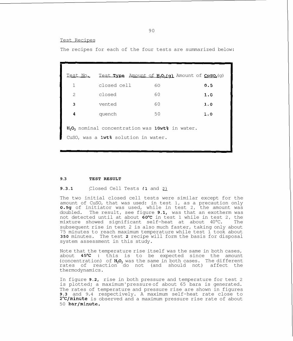
90
Test Recipes
The recipes for each of the four tests are summarized below:
--
Test No. Test TVDe Amount of H f i m Amount of CuSO, (g)
1 closed cell 6 0
2 closed 60
3 vented 60
4 quench 50
H20, nominal concentration was 10wt% in water.
CuSO, was a lwt% solution in water.
9.3 TEST RESULT
9.3.1 Closed Cell Tests (1 and 2 1
The two initial closed cell tests were similar except for the amount of CuSO, that was used: in test 1, as a precaution only 0.5g of initiator was used, while in test 2, the amount was doubled. The result, see figure 9.1, was that an exotherm was not detected until at about 60°C in test 1 while in test 2, the mixture showed significant self-heat at about 40°C. The subsequent rise in test 2 is also much faster, taking only about 75 minutes to reach maximum temperature while test 1 took about 350 minutes. The test 2 recipe will form the basis for disposal system assessment in this study.
Note that the temperature rise itself was the same in both cases, about 45'C : this is to be expected since the amount (concentration) of H,02 was the same in both cases. The different rates of reaction do not (and should not) affect the thermodynamics.
In figure 9.2, rise in both pressure and temperature for test 2 is plotted; a maximum'pressure of about 65 bara is generated. The rates of temperature and pressure rise are shown in figures 9.3 and 9.4 respectively. A maximum self-heat rate close to 2"C/minute is observed and a maximum pressure rise rate of about 50 bar/minute.
A feature of this reaction is that the pressure rise is caused by generation of non-condensible gas rather than liquid vapour pressure. This aspect is crucial for the present study and must be clearly established. In figure 9.5, the pressure from tests 1 and 2 is plotted against temperature, together with the vapour pressure of H202. It is clear that up to the point of exotherm onset, the test pressures are very close to H20, vapour pressure, but depart markedly when the reaction begins. The test pressures are slightly higher than H202 initially due to the pressure of N, in the test cell as well as early decomposition.
9.3.2 Disposal into Emptv Test Cell (Test 3 )
In this case the reactants within the PHI-TEC reaction cell were vented into the disposal cell. The results are shown in figure 9.6, where the temperature in the disposal cell is plotted alongside that in the reaction cell. The objective of the test was to demonstrate an important aspect of gassy reactions, namely that flash cooling does not occur when these systems are vented. The data in figure 9.6 shows that the vented reactants take up the same temperature as the reaction cell and both cells then continue to react in a virtually identical manner.
A more detailed view of the disposal cell is given in figure 9.7 where the pressure and temperature are both plotted. The pressure is initially atmospheric and after venting the disposal cell was "closed in ", leading to pressure rise. At about 1.4 barg, the vent valve in the cell was opened again and then reclosed, several times. The resulting pressure functions are clear in figure 9.7. The objective of this exercise was to demonstrate a further feature of gassy reactions, namely that venting will not temper the reaction ( i.e. will not prevent continued temperature rise). Clearly even if the vent valve is left open, the temperature will continue to rise generating further gas.
9 . 3 . 3 Ouench Test with Water (Test 4 1
In this fourth test the reaction was suppressed by successive injections of water, to determine the extent of cooling and dilution needed to suppress the reaction. A total of 509 of water was added in five equal amounts. The reaction temperature at the point of the first injection was 78'C and the self-heat rate was 1.8OC/minute (i.e. close to the peak rate).
The sequence of events that take place when water is added are the following:-
(i) at the time of injection, the vapour space in test cell is compressed and leads to a sharp pressure increase .
(ii) the temperature at the same time drops sharply

(iii) after the injection, the pressure and temperature both increase slowly due to continued reaction. After every addition, the self-heat rate decreases.
The results of the test are shown in figure 9.8, which is a detailed view of the last 3 water injections showing both pressure and temperature. Prior to the last injection of water, the self-heat rate was down to O.O5OC/rninute. The pressure was quite high at this point and was released by opening the vent valve so that the last shot of water could be added. Note that when the pressure was reduced, the temperature did not change - confirming the findings of test 3.
When the final log of water were added the self-heat rate was down to about 0.02'C/minute.
A summary of the results is as follows:-
Temperature Self-heat Rate Water added(cumu1ative) 'C/minute (9)
9.4. RELIEF SYSTEM DESIGN BASIS
9.4.1 Imvlications of Test Results
The pertinent tests in terms of relief and disposal assessment are tests 2 and 4. Test 2 shows that the maximum gas generation rate is about 51 bar/minute and occurs at about 78"C, from a reaction initiation temperature of below 40°C.' Relief of gassy reactions is based in the maximum gas generation rate.

In order to bring the reaction under control, approximately equal amount of quench water and H202 are required. This was confirmed in test 4.
9.4.2 Basis of Relief and Dis~osal SVstem
In keeping with the three previous disposal, systems designs a reaction volume of 4.54 m3 and a charge of 3628 kg of H,O,will be assumed.
The relief will be assumed to be at -40°C. Two disposal options will be considered:-
* atmospheric knock-out drum (without quench) atmospheric drum with quench water
It will be assumed that the reactants will vent as a homogeneous two-phase gas-liquid mixture.
9.5 DESIGN OF OPEN KNOCK-OUT DISPOSAL DRUM
If the reaction mixture is vented into an empty disposal drum, the reactants in the drum will be at the same temperatures as the material in the reactor. That is, there will be no flash cooling as the mixture is released from the reactor to atmospheric pressure. (This was demonstrated clearly in the tests.)
Therefore, the reaction will continue in the disposal drum and will presumably also vent out as a two-phase mixture. An empty disposal drum without quench water is inappropriate for this system.
9.6 DESIGN OF ATMOSPHERIC PRESSURE QUENCH DRUM
9.6.1 Suitabilitv of Ouench Option
In this case the disposal unit will contain cold water into which the reactants will be sparged. The liquid will be cooled but the gas from the reactor will not condense and must therefore be vented out of the drum.
This raises an important question for the disposal unit design; if the reaction vents as a homogeneous two-phase mixture, it may vent out of the quench drum, even after cooling with water.
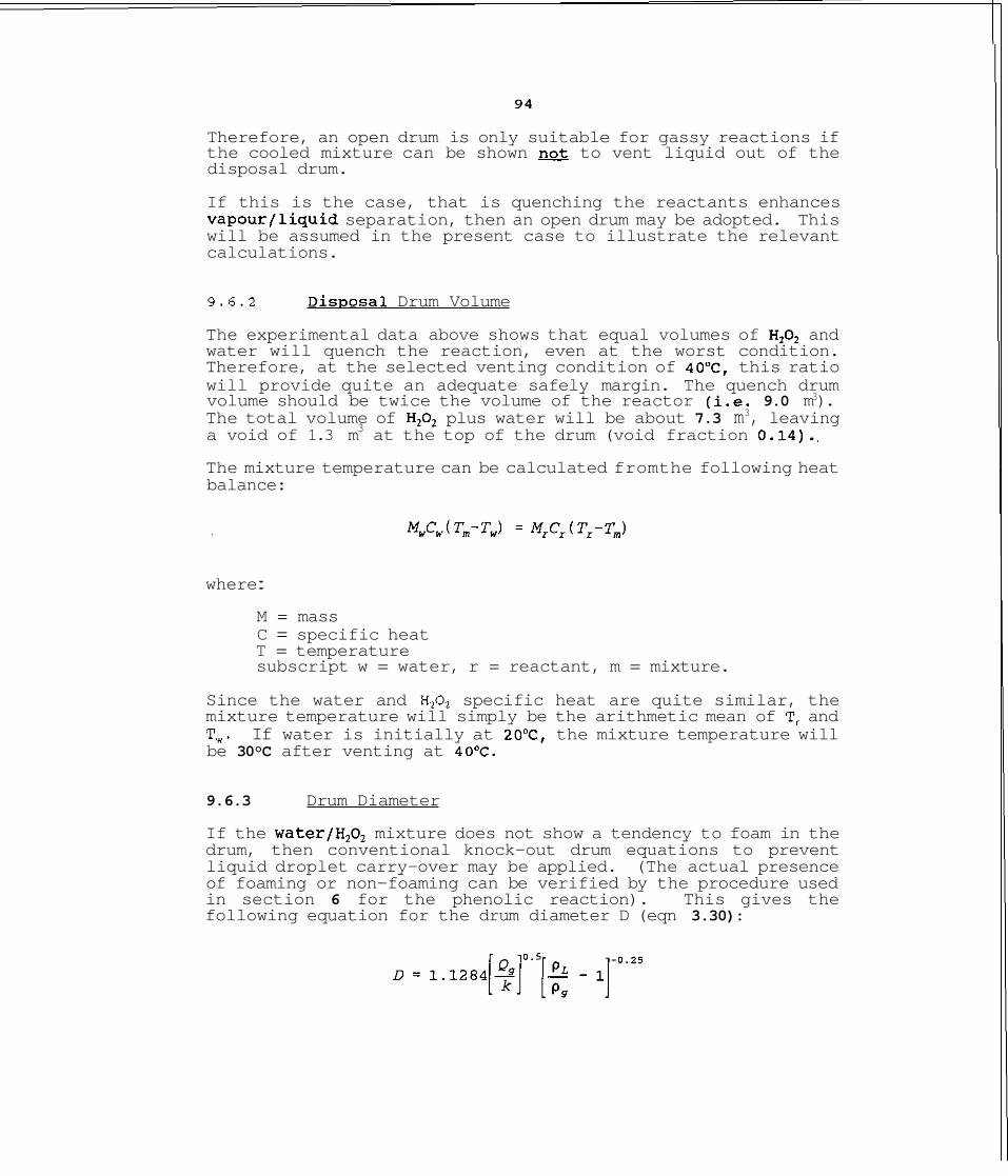
Therefore, an open drum is only suitable for gassy reactions if the cooled mixture can be shown to vent liquid out of the disposal drum.
If this is the case, that is quenching the reactants enhances vapourfliquid separation, then an open drum may be adopted. This will be assumed in the present case to illustrate the relevant calculations.
9.6.2 Dis~osal Drum Volume
The experimental data above shows that equal volumes of H,O, and water will quench the reaction, even at the worst condition. Therefore, at the selected venting condition of 40°C, this ratio will provide quite an adequate safely margin. The quench drum volume should be twice the volume of the reactor (i.e. 9.0 m3). The total volume of H,02 plus water will be about 7.3 m3, leaving a void of 1.3 m3 at the top of the drum (void fraction 0.14)..
The mixture temperature can be calculated fromthe following heat balance:
where :
M = mass C = specific heat T = temperature subscript w = water, r = reactant, m = mixture.
Since the water and H,O, specific heat are quite similar, the mixture temperature will simply be the arithmetic mean of T, and T,. If water is initially at 20°C, the mixture temperature will be 30°C after venting at 40°C.
9.6.3 Drum Diameter
If the water/H,O, mixture does not show a tendency to foam in the drum, then conventional knock-out drum equations to prevent liquid droplet carry-over may be applied. (The actual presence of foaming or non-foaming can be verified by the procedure used in section 6 for the phenolic reaction). This gives the following equation for the drum diameter D (eqn 3.30):
where :
Q, = gas flow (m3/s) p , = liquid density p, = gas density k = empirical constant: typically 0.04 for vertical drum.
The gas rate, Qg! is the same at that vented out of the reactor. This may be estimated from experimental data using the pressure rise in the test cell at the maximum gas rate.
The void space in the test cell (test 2) was about 60cc after addition of sample. The maximum rate of pressure rise was 8.5 x lo4 Pa/second (51 bar/minute). The rate of pressure rise is related to the gas generation rate by the gas law:
(P = pressure, m = mass of gas, M, = molecular weight of gas, R = gas constant, T = temperature).
This leads to,
where (m,/m,) is the scaling factor in going from test cell to large-scale drum.
The gas in this case oxygen (M, = 32), V - 60 x m3, R = 8314 Jlkmole K and T - 78'C (= 351" K) at the maximum gas rate. Since dP/dt = 8.5 x lo4 Pals, the gas rate is:
The gas density will be approximately 1 kg/m3 (in the atmospheric disposal drum), hence the gas volume will be 1.68 m3/s.
Therefore, substituting into the gas diameter equation:
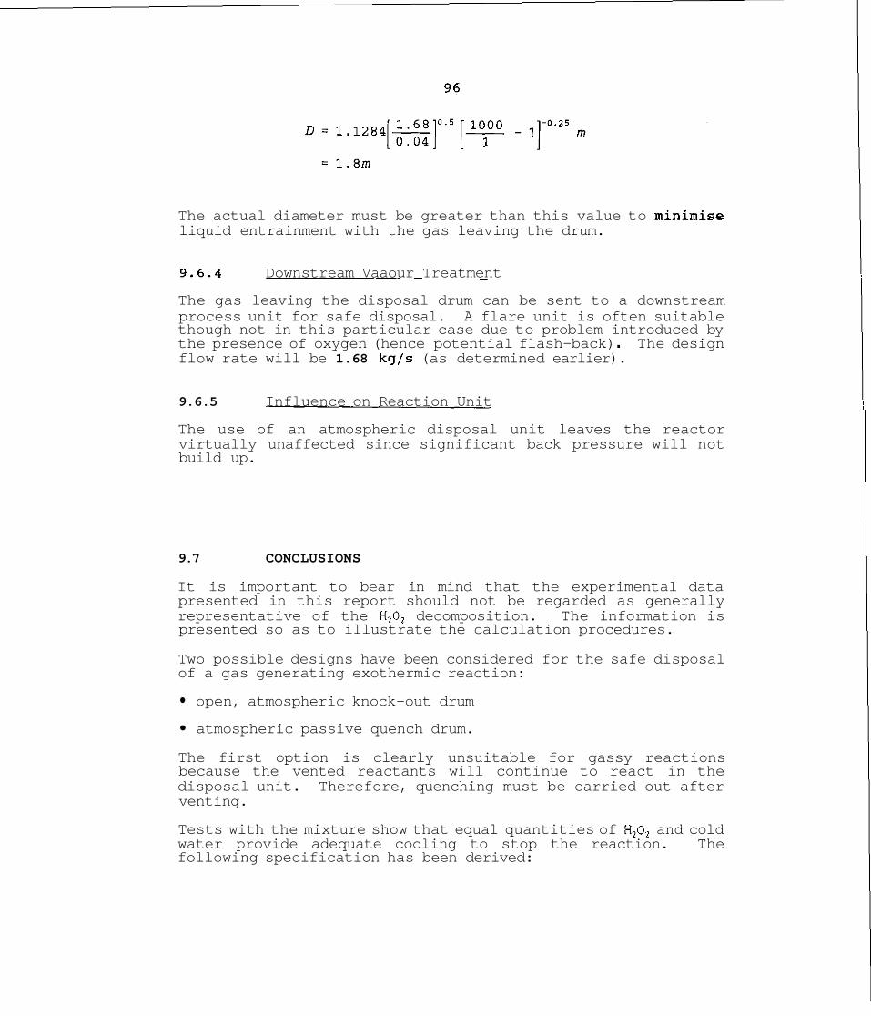
The actual diameter must be greater than this value to minimise liquid entrainment with the gas leaving the drum.
9.6.4 Downstream Vaaour Treatment
The gas leaving the disposal drum can be sent to a downstream process unit for safe disposal. A flare unit is often suitable though not in this particular case due to problem introduced by the presence of oxygen (hence potential flash-back) . The design flow rate will be 1.68 kg/s (as determined earlier).
9.6.5 Influence on Reaction Unit
The use of an atmospheric disposal unit leaves the reactor virtually unaffected since significant back pressure will not build up.
9.7 CONCLUSIONS
It is important to bear in mind that the experimental data presented in this report should not be regarded as generally representative of the H202 decomposition. The information is presented so as to illustrate the calculation procedures.
Two possible designs have been considered for the safe disposal of a gas generating exothermic reaction:
open, atmospheric knock-out drum
atmospheric passive quench drum.
The first option is clearly unsuitable for gassy reactions because the vented reactants will continue to react in the disposal unit. Therefore, quenching must be carried out after venting.
Tests with the mixture show that equal quantities of H,02 and cold water provide adequate cooling to stop the reaction. The following specification has been derived:
Reactor Volume : 4.5 m3
Quench Drum Volume : 9.0 m3
Quench Water : 3.6 m3
Maximum Gas Rate : 1.68 kg/s (-1.68 m3/s) from drum.
A quench drum open to the atmosphere with a vent gas line to relieve the above gas rate should be provided.
The above result represents a very conservative estimate because the maximum gas generation rate has been assumed. If the actual vent system dimensions are known, a more detailed evaluation will permit a more realistic design. This calculation procedure is described in section 3.4.

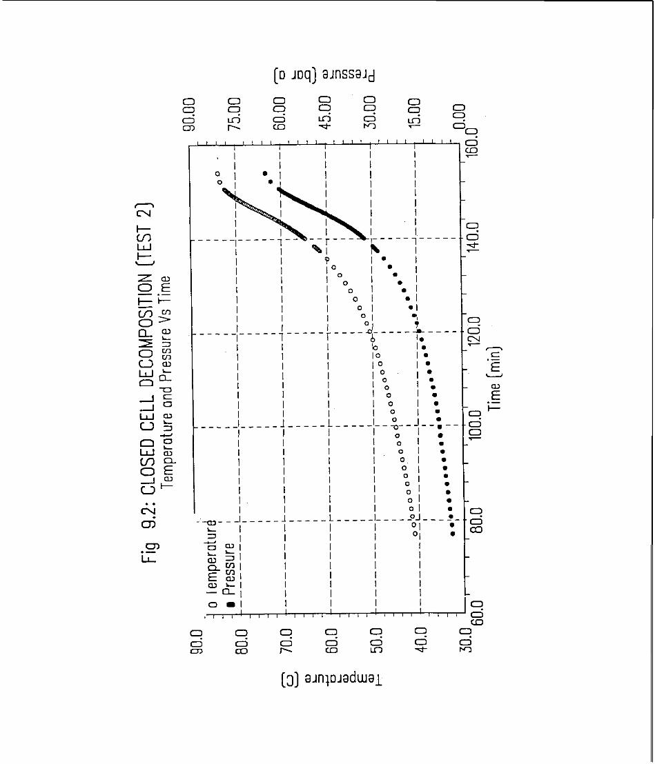
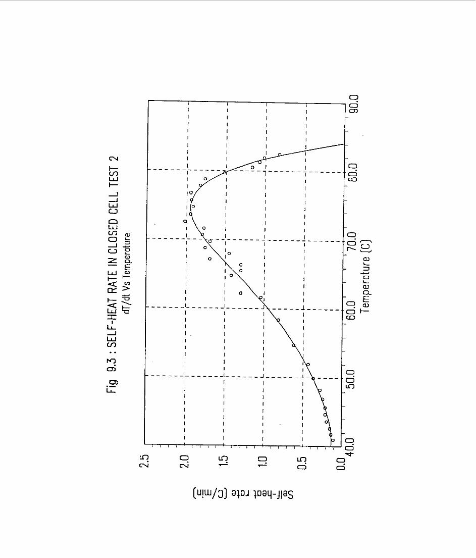

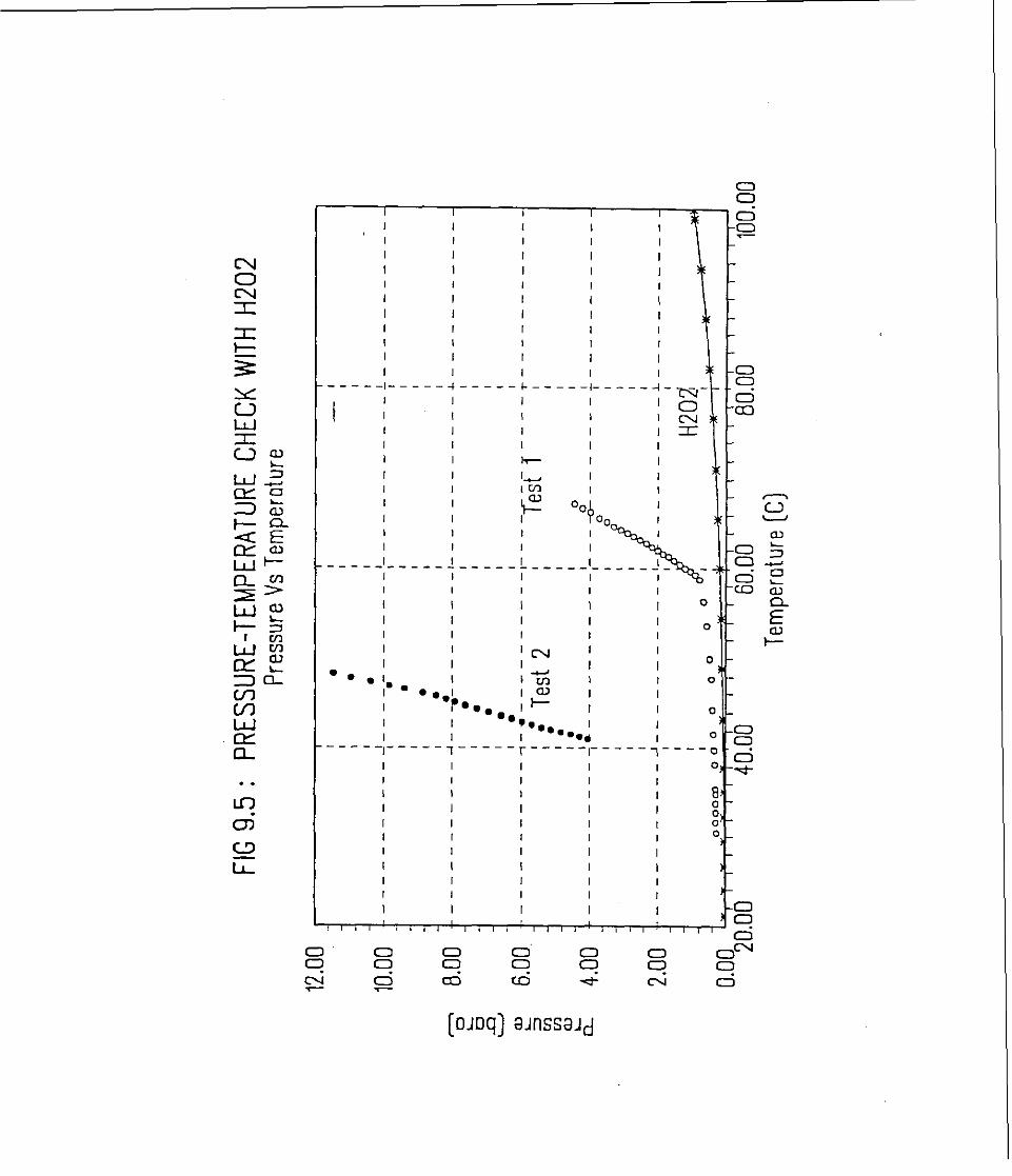

FIG 9.6: RELIEF INTO EMPTY DISPOSAL CELL [TEST 31 TEMPERATURE OF REACTION & DISPOSAL CELL Vs TIME
Y ." T i m e [min)
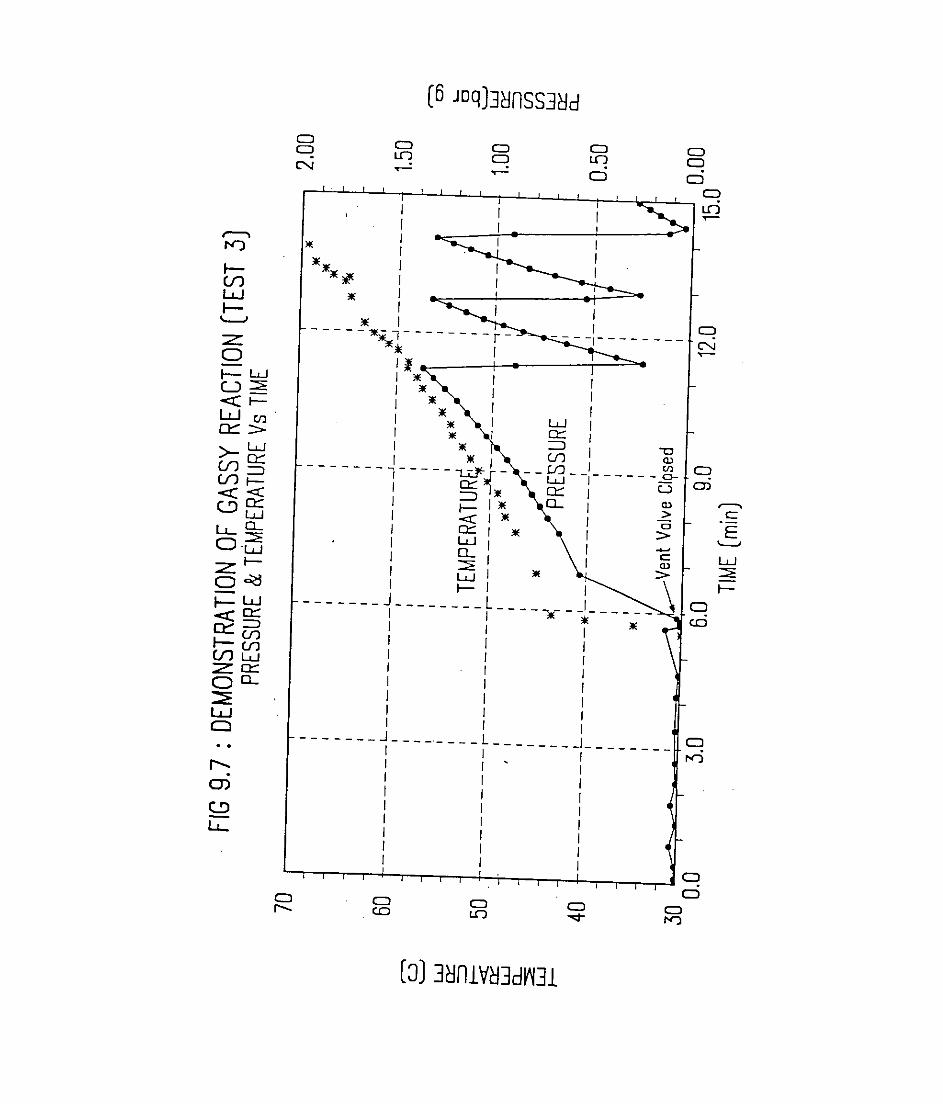
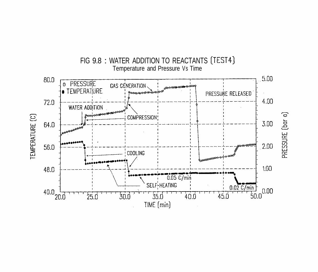
FIG 9.8 : WATER ADDITION TO REACTANTS [TEST41 Temperature and Pressure Vs Time
10. CONCLUSIONS
This report presents the results of a short research project to explore the design of disposal units downstream of chemical reactors, particularly where potential exists for exothermic runaway reaction. The objective of the disposal units is to eliminate (or at least reduce) the release of toxic and/or flammable chemicals into the atmosphere following an emergency relief incident. It addresses the safety and environmental problems associated with the comon practice of venting chemicals directly into the atmosphere, often involving the release of large quantities of both liquid and vapour/gas.
The design equations appropriate for different types of reactions have been presented and their application illustrated with four examples. A crucial element in the design is the availability of
.
subsequent reaction in the disposal vessel. The use of small scale equipment for establishing the data has been explored.
The experimental equipment used for the study, PHI-TEC, is an adiabatic calorimeter with certain special features that lend themselves to venting applications. A number of other devices could however be adapted and then used in a similar manner.
The treatment presented in this report is limited to low vlscoslty systems When the viscosity is hlgh (say above 100 cp) lammar flow nonnally occurs and thls is not yet fully understood and 1s an area of research
HSE BOOKS
MAIL ORDER HSE priced and free publications are available from: HSE Books PO Box 1999 Sudbury Suffolk COlO 6FS Tel:01787881 I65 Fax: 01 787 31 3995
RETAIL HSE priced publications are available from good booksellers.
PUBLIC ENQUIRY POINT Health and safety enquiries: HSE Information Centre Broad Lane Sheffield 53 7HQ Tel: 01 14 289 2345 Fax: 01 14 289 2333
CRR 100
ISBN 0-7176-1107-8
£30.00 net