crossrail at canary wharf
DESCRIPTION
Crossrail at Canary WharfTRANSCRIPT
50
proceedings
1 2 3 4
Innovative thinking and willingness to break with the norm were two of the main ingredients to successful delivery
of the first Crossrail station at Canary Wharf in London. For example, minimising the environmental impact of
construction activities in an urban environment led to the use of an innovative silent piling technique, which in
turn led to significant cost savings and cut a year off the programme. In addition, a flexible approach to design
development allowed continuous improvements in layout to be made to generate further cost and programme
savings, with additional savings arising during construction through adoption of the observational method.
1 Hoe Yeow BSc, PhD, Ceng, MiCe associate director, arup, UK
2 Duncan Nicholson MSc, Ceng, MiCe Director, arup, UK
3 Cliff Bryant FCiOB, MaPM executive director, Canary Wharf Contractors ltd, UK
4 Martin Westbury Beng, Ceng, MiCe Operations director, expanded ltd, UK
Proceedings of the Institution of Civil Engineers Civil engineering Special issue 165 May 2012 issue Ce5 Pages 50–57 http://dx.doi.org/10.1680/cien.11.00039 Paper 1100039
Received 01/08/2011 accepted 23/12/2011
Keywords: piles & piling/railway systems/transport planning
iCe Publishing: all rights reserved
Civil Engineering Special Issue Volume 165 issue Ce5
Achieving more for less at Canary Wharf Crossrail station, London Yeow, nicholson, Bryant and Westbury
Achieving more for less at Canary Wharf Crossrail station, London
Shenfield
Brentwood
Harold Wood
Romford
Chadwell Heath
Goodmayes
Abbey Wood
Custom HouseCanary Wharf
Liverpool Street
Tottenham Court Road
Woolwich
Seven Kings
IlfordManor Park
Forest Gate
Maryland
Stratford
Whitechapel
Farringdon
Bond Street
Southall
Hayes and Harlington
West Drayton
Heathrow
IverSloughMaidenhead
BurnhamTaplow
Langley
West Ealing
Hanwell
Acton Main Line
Ealing Broadway
Paddington
Gidea Park
Existing stationNew stationSurface lineTunnelTunnel portal
RiverThames
West India South dock
BlackwallBasin
Canary Wharf
Heron Quays
Crossrail station
West India Quay
DLR
m0 500
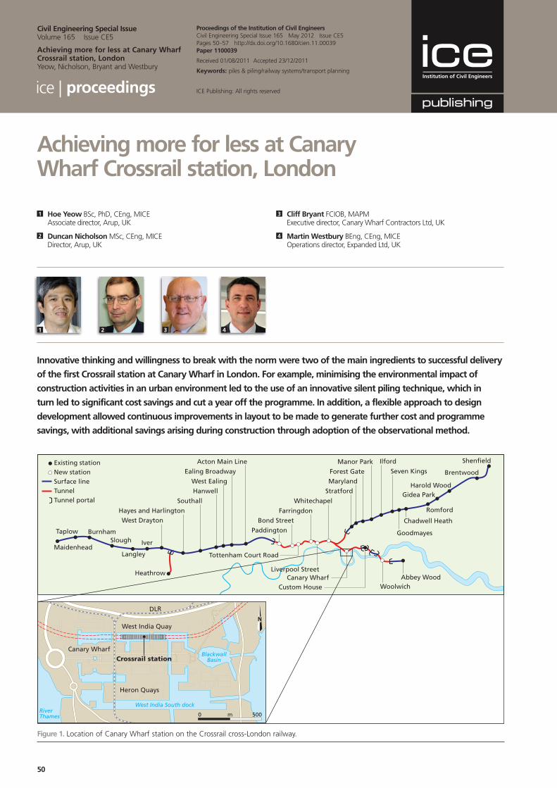
Figure 1. location of Canary Wharf station on the Crossrail cross-london railway.
51
Civil Engineering Special Issue Volume 165 issue Ce5 May 2012
Achieving more for less at Canary Wharf Crossrail station, London Yeow, nicholson, Bryant and Westbury
1. introduction
Canary Wharf Crossrail station is the first station on the Crossrail cross-London railway project to be constructed and, at the time of construction, the only one let as a design-and-build contract with developer Canary Wharf Group. It recently won the 2011 Ground Engineering award for technical excellence due to innovation in its design and construction techniques. Three years from inception, it is ahead of the development programme.
Early involvement of the developer in the project allowed significant optimisation of the station box design from the original Crossrail reference design scheme. Innovative thinking, local knowledge and willingness to break with the norm enabled the station to be delivered at 58% of the cost of the reference design.
This paper describes the success of the Canary Wharf Crossrail station project, outlining the early design work undertaken by the developer and its project management group Canary Wharf Contractors Ltd (the client), together with designer Arup and architect Tony Meadow Associates. Further design refinement was also undertaken once main contractor Expanded Ltd was appointed and executive architect Adamson joined the team.
2. Canary Wharf Crossrail station
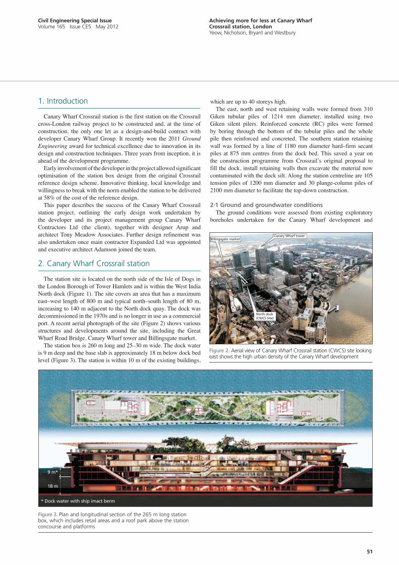
The station site is located on the north side of the Isle of Dogs in the London Borough of Tower Hamlets and is within the West India North dock (Figure 1). The site covers an area that has a maximum east–west length of 800 m and typical north–south length of 80 m, increasing to 140 m adjacent to the North dock quay. The dock was decommissioned in the 1970s and is no longer in use as a commercial port. A recent aerial photograph of the site (Figure 2) shows various structures and developments around the site, including the Great Wharf Road Bridge, Canary Wharf tower and Billingsgate market.
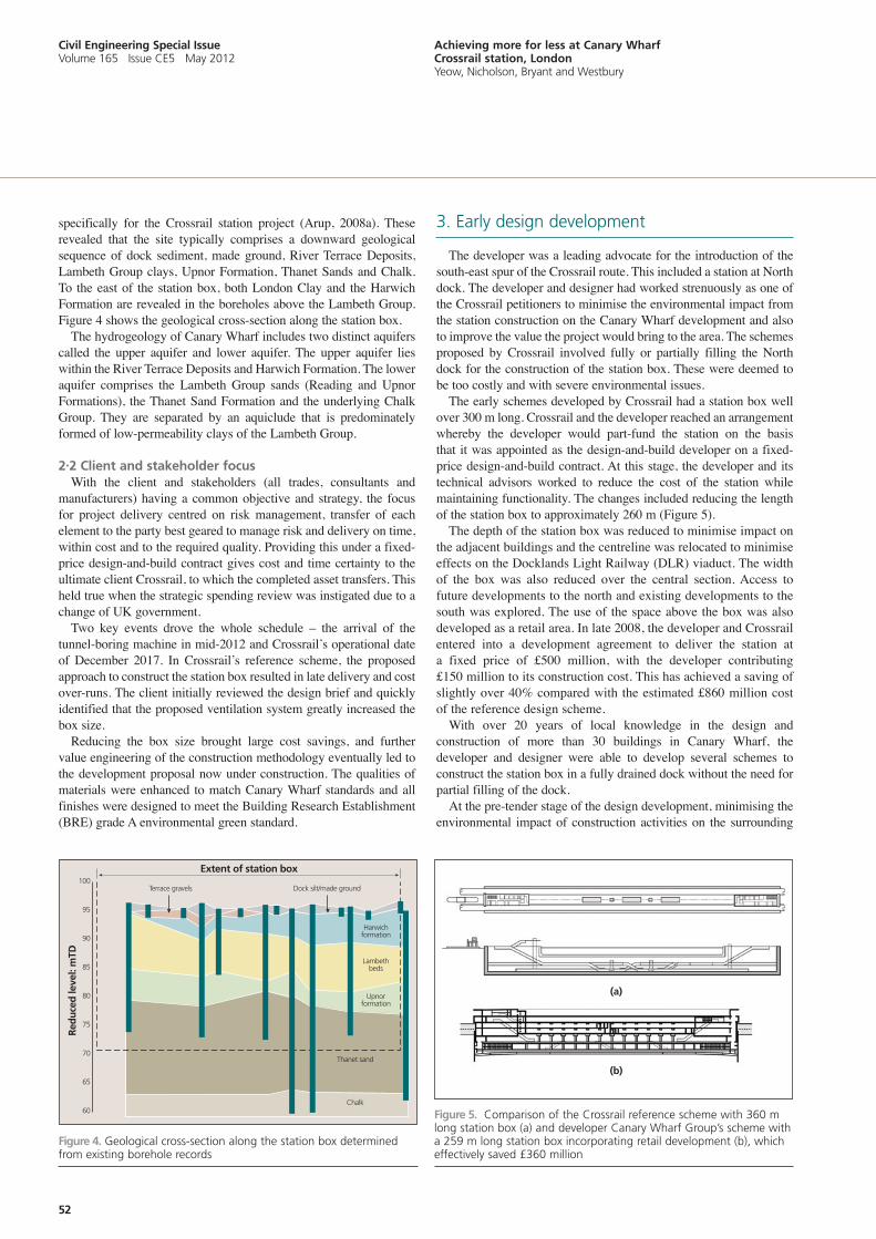
The station box is 260 m long and 25–30 m wide. The dock water is 9 m deep and the base slab is approximately 18 m below dock bed level (Figure 3). The station is within 10 m of the existing buildings,
which are up to 40 storeys high. The east, north and west retaining walls were formed from 310
Giken tubular piles of 1214 mm diameter, installed using two Giken silent pilers. Reinforced concrete (RC) piles were formed by boring through the bottom of the tubular piles and the whole pile then reinforced and concreted. The southern station retaining wall was formed by a line of 1180 mm diameter hard–firm secant piles at 875 mm centres from the dock bed. This saved a year on the construction programme from Crossrail’s original proposal to fill the dock, install retaining walls then excavate the material now contaminated with the dock silt. Along the station centreline are 105 tension piles of 1200 mm diameter and 30 plunge-column piles of 2100 mm diameter to facilitate the top-down construction.
2.1 Ground and groundwater conditionsThe ground conditions were assessed from existing exploratory
boreholes undertaken for the Canary Wharf development and
Figure 3. Plan and longitudinal section of the 265 m long station box, which includes retail areas and a roof park above the station concourse and platforms
Station
Figure 2. aerial view of Canary Wharf Crossrail station (CWCS) site looking east shows the high urban density of the Canary Wharf development
Billingsgate marketCanary Wharf tower
North dock(CWCS Site)
* Dock water with ship imact berm
9 m*
18 m
52
Civil Engineering Special Issue Volume 165 issue Ce5 May 2012
Achieving more for less at Canary Wharf Crossrail station, London Yeow, nicholson, Bryant and Westbury
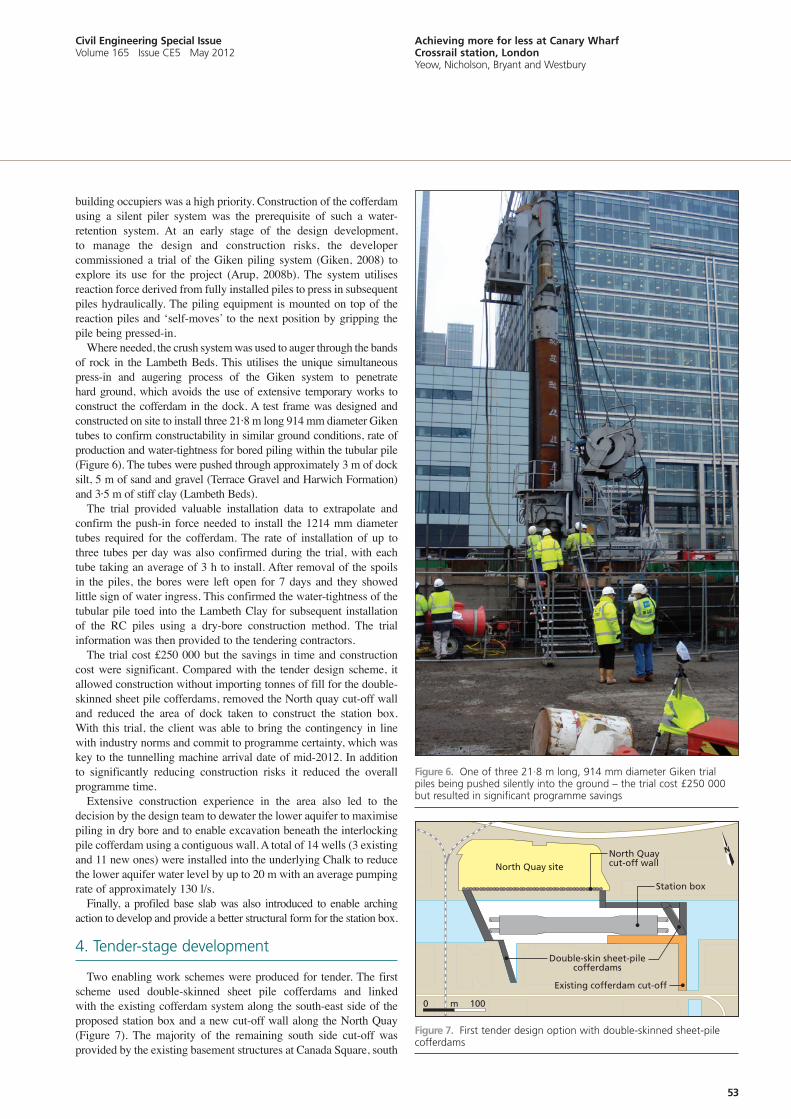
specifically for the Crossrail station project (Arup, 2008a). These revealed that the site typically comprises a downward geological sequence of dock sediment, made ground, River Terrace Deposits, Lambeth Group clays, Upnor Formation, Thanet Sands and Chalk. To the east of the station box, both London Clay and the Harwich Formation are revealed in the boreholes above the Lambeth Group. Figure 4 shows the geological cross-section along the station box.
The hydrogeology of Canary Wharf includes two distinct aquifers called the upper aquifer and lower aquifer. The upper aquifer lies within the River Terrace Deposits and Harwich Formation. The lower aquifer comprises the Lambeth Group sands (Reading and Upnor Formations), the Thanet Sand Formation and the underlying Chalk Group. They are separated by an aquiclude that is predominately formed of low-permeability clays of the Lambeth Group.
2.2 Client and stakeholder focusWith the client and stakeholders (all trades, consultants and
manufacturers) having a common objective and strategy, the focus for project delivery centred on risk management, transfer of each element to the party best geared to manage risk and delivery on time, within cost and to the required quality. Providing this under a fixed-price design-and-build contract gives cost and time certainty to the ultimate client Crossrail, to which the completed asset transfers. This held true when the strategic spending review was instigated due to a change of UK government.
Two key events drove the whole schedule – the arrival of the tunnel-boring machine in mid-2012 and Crossrail’s operational date of December 2017. In Crossrail’s reference scheme, the proposed approach to construct the station box resulted in late delivery and cost over-runs. The client initially reviewed the design brief and quickly identified that the proposed ventilation system greatly increased the box size.
Reducing the box size brought large cost savings, and further value engineering of the construction methodology eventually led to the development proposal now under construction. The qualities of materials were enhanced to match Canary Wharf standards and all finishes were designed to meet the Building Research Establishment (BRE) grade A environmental green standard.
3. early design development
The developer was a leading advocate for the introduction of the south-east spur of the Crossrail route. This included a station at North dock. The developer and designer had worked strenuously as one of the Crossrail petitioners to minimise the environmental impact from the station construction on the Canary Wharf development and also to improve the value the project would bring to the area. The schemes proposed by Crossrail involved fully or partially filling the North dock for the construction of the station box. These were deemed to be too costly and with severe environmental issues.
The early schemes developed by Crossrail had a station box well over 300 m long. Crossrail and the developer reached an arrangement whereby the developer would part-fund the station on the basis that it was appointed as the design-and-build developer on a fixed-price design-and-build contract. At this stage, the developer and its technical advisors worked to reduce the cost of the station while maintaining functionality. The changes included reducing the length of the station box to approximately 260 m (Figure 5).
The depth of the station box was reduced to minimise impact on the adjacent buildings and the centreline was relocated to minimise effects on the Docklands Light Railway (DLR) viaduct. The width of the box was also reduced over the central section. Access to future developments to the north and existing developments to the south was explored. The use of the space above the box was also developed as a retail area. In late 2008, the developer and Crossrail entered into a development agreement to deliver the station at a fixed price of £500 million, with the developer contributing £150 million to its construction cost. This has achieved a saving of slightly over 40% compared with the estimated £860 million cost of the reference design scheme.
With over 20 years of local knowledge in the design and construction of more than 30 buildings in Canary Wharf, the developer and designer were able to develop several schemes to construct the station box in a fully drained dock without the need for partial filling of the dock.
At the pre-tender stage of the design development, minimising the environmental impact of construction activities on the surrounding
Extent of station box
Terrace gravels Dock silt/made ground
Chalk
Thanet sand
Upnorformation
Lambethbeds
Harwichformation
100
95
90
85
80
75
70
65
60
Red
uce
d le
vel:
mTD
Figure 5. Comparison of the Crossrail reference scheme with 360 m long station box (a) and developer Canary Wharf Group’s scheme with a 259 m long station box incorporating retail development (b), which effectively saved £360 million
Figure 4. Geological cross-section along the station box determined from existing borehole records
(a)
(b)
53
Civil Engineering Special Issue Volume 165 issue Ce5 May 2012
Achieving more for less at Canary Wharf Crossrail station, London Yeow, nicholson, Bryant and Westbury
building occupiers was a high priority. Construction of the cofferdam using a silent piler system was the prerequisite of such a water-retention system. At an early stage of the design development, to manage the design and construction risks, the developer commissioned a trial of the Giken piling system (Giken, 2008) to explore its use for the project (Arup, 2008b). The system utilises reaction force derived from fully installed piles to press in subsequent piles hydraulically. The piling equipment is mounted on top of the reaction piles and ‘self-moves’ to the next position by gripping the pile being pressed-in.
Where needed, the crush system was used to auger through the bands of rock in the Lambeth Beds. This utilises the unique simultaneous press-in and augering process of the Giken system to penetrate hard ground, which avoids the use of extensive temporary works to construct the cofferdam in the dock. A test frame was designed and constructed on site to install three 21·8 m long 914 mm diameter Giken tubes to confirm constructability in similar ground conditions, rate of production and water-tightness for bored piling within the tubular pile (Figure 6). The tubes were pushed through approximately 3 m of dock silt, 5 m of sand and gravel (Terrace Gravel and Harwich Formation) and 3·5 m of stiff clay (Lambeth Beds).
The trial provided valuable installation data to extrapolate and confirm the push-in force needed to install the 1214 mm diameter tubes required for the cofferdam. The rate of installation of up to three tubes per day was also confirmed during the trial, with each tube taking an average of 3 h to install. After removal of the spoils in the piles, the bores were left open for 7 days and they showed little sign of water ingress. This confirmed the water-tightness of the tubular pile toed into the Lambeth Clay for subsequent installation of the RC piles using a dry-bore construction method. The trial information was then provided to the tendering contractors.
The trial cost £250 000 but the savings in time and construction cost were significant. Compared with the tender design scheme, it allowed construction without importing tonnes of fill for the double-skinned sheet pile cofferdams, removed the North quay cut-off wall and reduced the area of dock taken to construct the station box. With this trial, the client was able to bring the contingency in line with industry norms and commit to programme certainty, which was key to the tunnelling machine arrival date of mid-2012. In addition to significantly reducing construction risks it reduced the overall programme time.
Extensive construction experience in the area also led to the decision by the design team to dewater the lower aquifer to maximise piling in dry bore and to enable excavation beneath the interlocking pile cofferdam using a contiguous wall. A total of 14 wells (3 existing and 11 new ones) were installed into the underlying Chalk to reduce the lower aquifer water level by up to 20 m with an average pumping rate of approximately 130 l/s.
Finally, a profiled base slab was also introduced to enable arching action to develop and provide a better structural form for the station box.
4. Tender-stage development
Two enabling work schemes were produced for tender. The first scheme used double-skinned sheet pile cofferdams and linked with the existing cofferdam system along the south-east side of the proposed station box and a new cut-off wall along the North Quay (Figure 7). The majority of the remaining south side cut-off was provided by the existing basement structures at Canada Square, south
m0 100
North Quay siteNorth Quaycut-off wall
Station box
Existing cofferdam cut-off
Double-skin sheet-pilecofferdams
Figure 7. First tender design option with double-skinned sheet-pile cofferdams
Figure 6. One of three 21·8 m long, 914 mm diameter Giken trial piles being pushed silently into the ground – the trial cost £250 000 but resulted in significant programme savings
54
Civil Engineering Special Issue Volume 165 issue Ce5 May 2012
Achieving more for less at Canary Wharf Crossrail station, London Yeow, nicholson, Bryant and Westbury
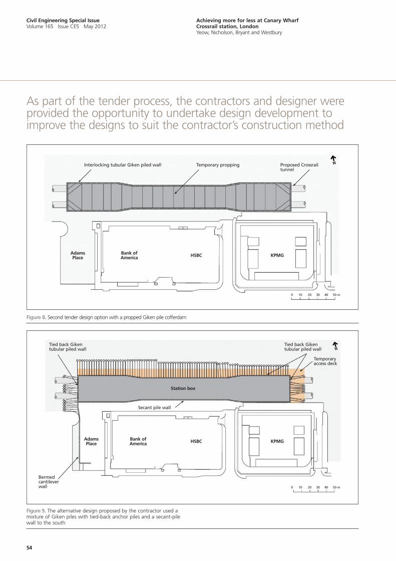
Figure 9. The alternative design proposed by the contractor used a mixture of Giken piles with tied-back anchor piles and a secant-pile wall to the south
Figure 8. Second tender design option with a propped Giken pile cofferdam
as part of the tender process, the contractors and designer were provided the opportunity to undertake design development to improve the designs to suit the contractor’s construction method
Interlocking tubular Giken piled wall
AdamsPlace
AdamsPlace
Bank ofAmerica
Bank ofAmerica
HSBC
HSBC
Station box
KPMG
KPMG
0 10 20 30 40 50 m
0 10 20 30 40 50 m
Temporary propping Proposed Crossrailtunnel
Tied back Gikentubular piled wall
Tied back Gikentubular piled wall
Temporaryaccess deck
Secant pile wall
Bermedcantilever wall
55
Civil Engineering Special Issue Volume 165 issue Ce5 May 2012
Achieving more for less at Canary Wharf Crossrail station, London Yeow, nicholson, Bryant and Westbury
of the proposed station box. This enabled the station box construction work to be carried out from the base of the drained dock in relatively open conditions.
The second scheme used cofferdams made from interlocking tubular Giken piles jacked down to the Lambeth Beds clay and then extended using RC piles to form a contiguous wall, with temporary propping across the station box (Figure 8). In this case the tension piles would be installed from a temporary deck at dock water level.
As part of the tender process, the contractors and designer were provided the opportunity to undertake design development to improve the designs to suit the contractor’s construction method. This allowed the contractors an insight of the design intent and gave the designer an understanding of the preferred construction method.
5. Post-tender design development
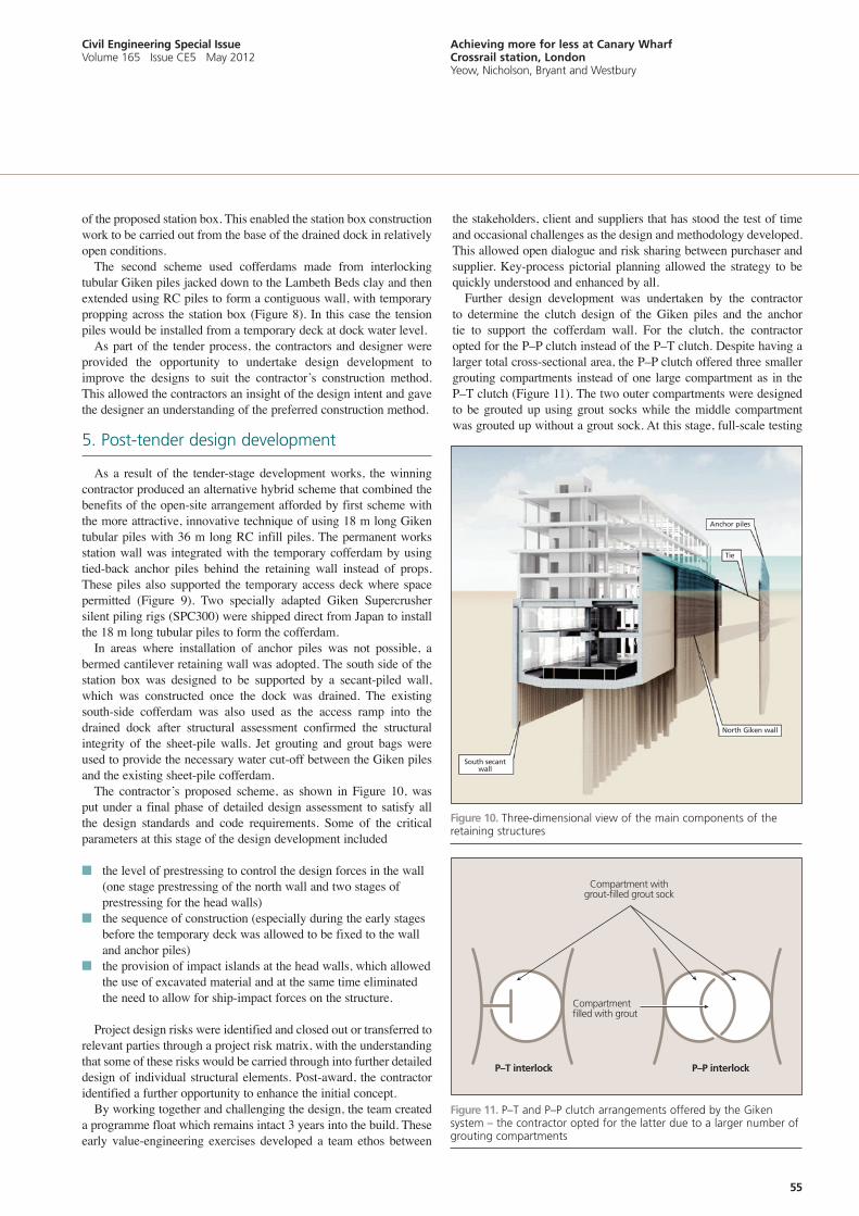
As a result of the tender-stage development works, the winning contractor produced an alternative hybrid scheme that combined the benefits of the open-site arrangement afforded by first scheme with the more attractive, innovative technique of using 18 m long Giken tubular piles with 36 m long RC infill piles. The permanent works station wall was integrated with the temporary cofferdam by using tied-back anchor piles behind the retaining wall instead of props. These piles also supported the temporary access deck where space permitted (Figure 9). Two specially adapted Giken Supercrusher silent piling rigs (SPC300) were shipped direct from Japan to install the 18 m long tubular piles to form the cofferdam.
In areas where installation of anchor piles was not possible, a bermed cantilever retaining wall was adopted. The south side of the station box was designed to be supported by a secant-piled wall, which was constructed once the dock was drained. The existing south-side cofferdam was also used as the access ramp into the drained dock after structural assessment confirmed the structural integrity of the sheet-pile walls. Jet grouting and grout bags were used to provide the necessary water cut-off between the Giken piles and the existing sheet-pile cofferdam.
The contractor’s proposed scheme, as shown in Figure 10, was put under a final phase of detailed design assessment to satisfy all the design standards and code requirements. Some of the critical parameters at this stage of the design development included
n the level of prestressing to control the design forces in the wall (one stage prestressing of the north wall and two stages of prestressing for the head walls)
n the sequence of construction (especially during the early stages before the temporary deck was allowed to be fixed to the wall and anchor piles)
n the provision of impact islands at the head walls, which allowed the use of excavated material and at the same time eliminated the need to allow for ship-impact forces on the structure.
Project design risks were identified and closed out or transferred to relevant parties through a project risk matrix, with the understanding that some of these risks would be carried through into further detailed design of individual structural elements. Post-award, the contractor identified a further opportunity to enhance the initial concept.
By working together and challenging the design, the team created a programme float which remains intact 3 years into the build. These early value-engineering exercises developed a team ethos between
the stakeholders, client and suppliers that has stood the test of time and occasional challenges as the design and methodology developed. This allowed open dialogue and risk sharing between purchaser and supplier. Key-process pictorial planning allowed the strategy to be quickly understood and enhanced by all.
Further design development was undertaken by the contractor to determine the clutch design of the Giken piles and the anchor tie to support the cofferdam wall. For the clutch, the contractor opted for the P–P clutch instead of the P–T clutch. Despite having a larger total cross-sectional area, the P–P clutch offered three smaller grouting compartments instead of one large compartment as in the P–T clutch (Figure 11). The two outer compartments were designed to be grouted up using grout socks while the middle compartment was grouted up without a grout sock. At this stage, full-scale testing
P–P interlockP–T interlock
Compartmentfilled with grout
Compartment withgrout-filled grout sock
Figure 11. P–T and P–P clutch arrangements offered by the Giken system – the contractor opted for the latter due to a larger number of grouting compartments
Figure 10. Three-dimensional view of the main components of the retaining structures
Anchor piles
Tie
North Giken wall
South secantwall
56
Civil Engineering Special Issue Volume 165 issue Ce5 May 2012
Achieving more for less at Canary Wharf Crossrail station, London Yeow, nicholson, Bryant and Westbury
of the tie was also undertaken by the contractor to confirm the load capacity of the tie.
The station box and its surrounding existing structures were analysed using two-dimensional finite-element software to capture the complex soil–structure interaction behaviour. This enabled the station box to be designed to allow for the influence of the construction of the station on these structures. Due to the dock water behind the cofferdam wall on the north side, the whole structure was noted to sway to the south during construction. A 20 mm sway movement was predicted but only 10 mm was measured during the work.
6. Construction phase
Construction of the station was undertaken using a top-down construction sequence. The major stages were
n dewatering of the lower aquifern probing for unexploded ordnance for piles installed from bargesn installation of the cofferdam steel tubular piles and RC piles on
the east, north and west sides of the siten installation of the anchor piles on the east, north and part of the
west sides of the cofferdamn construction of the berm of part of the west side cofferdamn prestressing the anchor tien draining the dockn clearing dock silt and installing piling platform n probing for unexploded ordnance for piles installed from
drained dock bedn construction of the secant-piled wall on the south side, the
plunge-column piles and the tension pilesn undertaking top-down construction by excavating and installing
level −3, −4 and −6 slabs and, at the appropriate time, constructing the level −2, −1 and 0 slabs
n flooding the site after completion of the station box structure.
About 100 000 m3 of dock water was pumped out during the dock draining work. During excavation, a total of 135 000 m3 of soil was excavated from the station box and about 35% of this material was reused to create ship-impact berms and a flood-storage reservoir south of the station box.
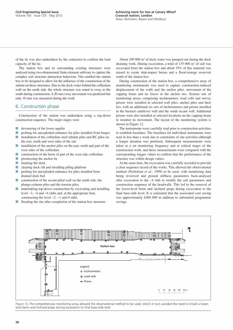
During construction of the station box, a comprehensive array of monitoring instruments was used to capture construction-induced displacement of the walls and the anchor piles, movement of the capping beam and tie forces in the anchor ties. Sixteen sets of monitoring arrays comprising inclinometers, load cells and survey prisms were installed in selected wall piles, anchor piles and their ties, with an additional six sets of inclinometers and prisms installed in the bermed cantilever wall and the south secant wall. Additional prisms were also installed at selected locations on the capping beam to monitor its movement. The layout of the monitoring system is shown in Figure 12.
The instruments were carefully read prior to construction activities to establish baselines. The baselines for individual instruments were read in less than a week due to constraints of site activities although a longer duration was preferred. Subsequent measurements were taken at a set monitoring frequency and at critical stages of the construction work, and these measurements were compared with the corresponding trigger values to confirm that the performance of the structure was within design values.
At the same time, the excavation was carefully recorded to provide a clear sequence record of the works. This allowed the observational method (Nicholson et al., 1999) to be used, with monitoring data being reviewed and ground stiffness parameters back-analysed after excavation to the –4 slab to modify the soil parameters and construction sequence of the headwalls. This led to the removal of the lower-level berm and inclined props during excavation to the final base-slab level. It is estimated that the associated cost saving was approximately £500 000 in addition to substantial programme savings.
Figure 12. The comprehensive monitoring array allowed the observational method to be used, which in turn avoided the need to install a lower-level berm and inclined props during excavation to final base-slab level
Station box
0 10 20 30 40 50 m
Legend
Inclinometers
Load cells
Prisms
57
Civil Engineering Special Issue Volume 165 issue Ce5 May 2012
Achieving more for less at Canary Wharf Crossrail station, London Yeow, nicholson, Bryant and Westbury
6.1 Approach to riskRisk to the client is seen as a manageable commodity, as
demonstrated on this project; each element of the project was broken down into separate work streams to enable the team to understand the deliverables, methodology and scope to minimise risk. Where a methodology had not been previously employed at Canary Wharf, desk studies ensued, followed by site visits to other works where the technology or methodology had been employed; in extreme cases, full-scale mock-ups were implemented.
Once the technology or method had been proven and the team was satisfied, the project could be undertaken to the required quality, time and cost requirements. Specialist trades, manufacturers and suppliers were engaged through tender to validate the client’s way of working. Their knowledge was then applied to refine the works further.
Continuing the process through the tender period, post-award and throughout the detailed design further reduced the cost and increased the contingency.
7. Conclusions
The involvement of the developer early in the design development stage of Canary Wharf Crossrail station has significantly reduced the cost of delivering the first station box for the Crossrail project from about £860 million to £500 million, with a £150 million contribution from Canary Wharf Group. This was achieved by a team with extensive local experience in the design and construction techniques of underground structures in Canary Wharf.
Early design development relied heavily on the existing cofferdam on the south side of the station site to provide the necessary water cut-off and this has proven to work well. This early works explored many design scenarios with different levels of confidence in the make-up of the south-side water retention.
The project also allowed an innovative method of construction
well suited to an urban environment where environmental impacts in the form of construction noise and vibration need to be kept to a minimum for successful implementation. The developer invested significantly in a silent piling trial and adoption of this new construction technique minimised construction risk and reduced the programme by a whole year.
The key to achieving the ambitious construction programme was to minimise heavy marine operations by draining the dock for the installation of the south retaining wall and the internal tension and plunge-column piles. The contractor also utilised part of the existing cofferdam as its access onto the dock after it was drained. This eliminated the need for imported fill to create an access ramp.
The station has many constraints and the layout and construction sequence evolved over time. This flexible approach to design development involved continuously testing the design to see if additional layout improvements could be made, together with cost and programme savings. The interactive involvement of the client, designer and contractor was important throughout this process.
During construction, establishing baseline readings for the monitoring instruments was another important activity that took significant efforts to achieve. Without confidence in these baseline readings, the programme and cost savings achieved from the change in the construction sequence for the headwalls would have been difficult to realise.
The success of the project has been acknowledged by the UK government, Crossrail, the client and stakeholders. It has set standards adopted by Crossrail and has been acknowledged by peers through awards for engineering excellence, safety and the environment.
acknowledgement
The authors would like to thank all who worked on the project for their efforts in the delivery of this first station for the Crossrail project.
References
arup (2008a) Geotechnical Interpretative Report. arup, london, UK.arup (2008b) Giken Piling Trial Report. arup, london, UK.Giken (2008) Construction Revolution – Silent Piling Technology. Giken
Seisakusho Co. ltd, Kochi, Japan.nicholson D, Tse CM and Penny C (1999) The Observational Method in
Ground Engineering – Principles and applications. CiRia, london, UK, Report 185.
What do you think?
if you would like to comment on this paper, please email up to 200 words to the editor at [email protected].
if you would like to write a paper of 2000 to 3500 words about your own experience in this or any related area of civil engineering, the editor will be happy to provide any help or advice you need.
The success of the project has been acknowledged by the UK government, Crossrail, the client and stakeholders. it has set standards adopted by Crossrail and has been acknowledged by peers through awards for engineering excellence, safety and the environment.