criticalreview - federation of american scientists · · 2016-10-211. thermochemicalproductionof...
TRANSCRIPT

—
LA-UR - 78- 2996
&$
10s.
~~: THEmCH~ICAL PRODUCTION OF HYDROGEN FROM UATER, A
CRITICAL REVIEW
AUTHOR(S): K. (3IX (CMB-3)
SUEMITI’IIIJ TO: To be presented by R. Krakowsicf(CTR-?2) at
the USA/USSR Workshop on Alternative Uses of
Fusion Energy, Kurchatov High Temperature In-
stitute, Mosccw, USSR (20-24 November 1978)
By Wqmttc40fthkutkle, tbopubhbwm-tithUS.G 0v4mnHnt rmlas m 00*oxclush, royalty=frwticamtopublhh orreptmduc4thapublhb4dfofmofthhcontrlbudon, ortodOW OthOH tO do SO, fot Us. Gmrnntantpurpm
moL.4muttlossctatltlnc Labomtolyrq- tbmttb, publbaoridmtify tblouUtiMwork porfMMumdsrtbo altqias of tba ~nt 0( ~.
)alamosIt
selontitio mbarmoryof tho Univorci* of California
> LOS AlAM@S, N~W MCXICO 07B4S
/\An Afhnatho ActIon /Cqual Opportunity Employor
Form NO. 836 RZSt.NO. 26291/78 DEPAR’IWNT OF ENERGY
CONTRACTW~740&~0. 36
‘$,’“s
.
\

1
THERMOCHEMICALPRODUCTION OF HYDROGEN FROM WATER, A CRITICAL REVIEW
EXECUTIVE SUMMARY
This report has assessedthe current status of thermochemicalhydrogen
technology as regards process chemistry, preliminary chemical engineering design
and techno-economicsfor a number of cycles undergoing active research and
development efforts throughout the world at this time.
Three cycles are receiving the bulk of the total effort and most of the
funding:
o In the USA, the cycles are:
1. The Hybrid Sulfuric Acid cycle - Westinghouse.
2. The Sulfuric Acid-fiydrogenIodide cycle - General Atomic.
o Ir Europe:
3. The Hybrid Sulfuric Acid-Hydrogen Bromide Cycle - Euratom (Mark 13).
All three cycles are at the stage where a laboratory scale continuous plant can
be or is in operation, The only plant (100 ?!ters of hydrogen per hour) in
operation is one at Ispra, Italy on the Mark 13 cycle. Both Westinghouse and
General Atomic have been funded and expect operation of theli+ciosed-circuit
laboratoryunits by the end of 1978 or early 1979. These plants will develop
data to assess:
o reference design conversions and concentrations,
o control problems for operating equipment,
o materials problems, especially corrosion in sulfuric acid service, and
o possible by-product formation and their elimination.
At the design level of these plants, no accurate evaluation of plant capital
cost or overall thermal efficiency of the cycle is possible, however, data for
the design of the next (larger) scale-up should be obtained that will aid in
determining these quantities.
Two other cycles were noted:
4. The Hybrid Bismuth Sulfate cycle - Los Alamos Scientific Laboratory,
and
5. The Magnesium-Iodinecycle - NCLI, Japan,
The LASL cycle, in principle, offers an improvementover the earlier-mentioned
cycles in two areas. By avoiding the handling of sulfuric acid other than at

2
reasonable temperature, pressure and
heat penalty problems are minimized;
for the hydrogen generation reaction
concentration (5-50%), the corrosion and
in addition, the electrochemicalvoltage
may be lowered as a result of operating at
low acid strengths. The Japanese cycle is included to illustrateefforts in
other countries. Serious difficulties exist in this cycle as a result of low
conversion, mutual volubility of intermediateconpounds and large quantities of
water that require evaporation.
Materials problems are endemic to all cycles. In most cases reference
materials for the sulfuric acid vaporization stages and the sulfuric acid or
sulfur trloxide decomposition vessels have not yet been defined. A prime
difficulty is the need for the vessel walls to transmit heat to interior fluids
as well as withstand their corrosive effects. Serious efforts must be
undertaken in the materials area prior to demonstrationof any of the sulfuric
acid-based cycles on a pilot plant scale under realistic pressure (30 atm) and
temperature conditions.
In the area of techno-economics,several studies have been done mainly
under assumed conditions. The most studied cycle has been the hybrid sulfuric
acid cycle (Westinghouseand Ispra Mark 11). Values of efficiency and cost ~re
developed in early reports by Westinghouse on the basis of “overly optimistic”
operating :onditions. These gave efficiencies in the 50%+ range at costs for
product hydrogen at around $5/106 BTU. Since that time, Euratom (Ispra) and
further Westinghotisestudies have shown values in the 35 to 45% range for the
efficiency, and costs from $7 to $10/1016 BTU for the hydrogen produced.
Heat penalty analysis has been applied by Funk and Knoche to determine the
irreversibilities In the different steps of a thermochemicalcycle. ~ese heat
penalties can be directly related to the capital cost and the hydrogen
production cost for a thermochemicalcycle. The method has been applied with
success to the hybrid sulfuric acid cycle (however, under assumed operating
conditions) to obtain cost and efficiency similar to the latter ones quoted
above. Part of the problem of using this method is the lack of reliable
thermodynamic data. These are gradually being accumulated for key substances
such as sulfuric acid, etc.
In the comparison of electrolysis of water with thermochemicalcycles for
producing hydrogen, exponents of both technologies have emerged.

3
Techno-economicassessments
have been performed at both
of these competing processes to produce hydrogen
Euratom and at Westinghouse recently. These have
shown small differences “inefficiency and cost between thermochemicalcycles
electrolysis. The va!ues obtained are as follows:
and
Process Efficiency (%) Cost ($/106/BTU)
Thermochemical
Ispra
ISpP-
Electrolysis
Mark ?1 41.2 8.02
Mark 13 37.2 8.88
wse FM 47,0 7.30
( Ispr, 32.7 8.54
Westinghouse 40.9 7.80
It appears reasonable to state that at this point in thermochemicalcycle
development, the differences shown above are not truly significant in view of
the uncertainty in the estimation procedure. Both the thermochemicaland the
water electrolysis systems require further development to substantiate the
assumptions used in
design, and process
technologies should
factual information
flowsheet definition, performance capability, component
economics, In view of this point, continued efforts in both
be strongly supported by vigorous funding designed to obtain
to make a clear-cut case favoring either one or the other
options for hydrogen production from water. This will probably take a 10
year developmentaltime period and, in view of the elasticity afforded by
price of synthetic hydrogen, it will allow adequate time to fully explore
options before choosing a single thermochemical cycle or water electro?ys.
process fov commercialization.
INTRODUCTION
to 15
the
s
Currently there is widespread interest in the develc~pmentof a “hydrogen
economy” as an eventual solu’tiunto many of the problems associated with the
energy crisis. Hydrogen deserves serious consideration +n ensuring a continuing
gaseous fuel supply as it can be manufactured from a vari[qtyof thermal energy
sources, and water - a relatively inexhaustibleresource. Many studies have

4
been published that discuss the advantages and disadvantages associated with
use of hydrogen as an energy carrier or “medium” for energy storage, energy
transmission, and indeed for large-scale use as a non-pollutingfuel.
Technologies that produce hydrogen at high energy efficiencies are being
developed and improved to provide a usable technolc~gybase for the future.
the
In addition to the potential for a “hydrogen economy”, it is important to
emphasize that hydrogen is a very valuable chemical cotmnoditythat is used in
large volume for the production of anwnonia,methanol, and in chemical
processing. Requirements for these applications are increasing rapidly and it
is clear that expanded production of hydrogen is necessary. It is equally clear
that fossil fuel supplies are becoming inadequate to satisfy the demand for
hydrogen, and that coal, a major fossil resource, not only is finite, bht its
use involves placing severe burdens on the environment such as the increasing
level of c’arbondioxide in the earth’s atmosphere. Large-scale hydrogen
production must, therefore, util!ze “renewable” primary energy sources such as
nuclear fission, fusion, and/or solar energy for the decompositionof water by
thermochemicalcycles, electrolysis,or perhaps, by hybrid combinations of these
methods.
Hydrogen is attractive as an alternative fuel for several reasons, some of
which are listed: (a) It provides a high energy density storable chemical form
of energy; (b) It can be synthesized from “renewable”energy supplies and water;
(c) On combustion, water is essentialIy the only product, thus completely
compatible with the environment. After substitute natural gas (SNG), hydrogen
has the best prospects for supplementingnatural gas supplies (to 45 million US
customers) without major changes to existing equipment for delivery and use of
fuel gasol
in regard to producing hydrogen by water-splitting,the potential higher
efficiency and lower cost for thermochemical cycles, versus the overall
electrolysis path (involving large 10SSIA due to mechanical irreversibilitiesin
power generation) has been rather widely recognized. As a consequence, several
laboratories throughout the world are conducting programs to develop
thermochemical processes for water decomposition. A large nunher of
thermochemical cycles have been conceived. Unfortunately,many of these have
been published without experimental verification of the reactions in the cycle.
5
As a resu’
processes
reaction conditions that have not been actually achieved.
cycles have now been published where all of the reactions
proven experimentally. As a consequence, the development
engineering and cost analysis for this new technology can
t of this, most evaluations and/or comparisons of thermochemical
for process efficiency and cost have been on assumed data or on
Nevertheless, several
in the cycle have been
of methodology for the
now be based with some
firmness on the actual chemistry involved in the
There are three important and inter-related
thermochemical hydrogen production process:
o Thermal efficiency,
o Capital ccst, and
o Operating cost.
demonstrated cycles.
parameters which characterize a
The meaning of capital cost and operating cost is clear, however, it is
necessary to carefully identify all of the assumptions that enter into deriving
these values. The
the ratio of the h
286 kJ/mol) to the
production process,
thermal efficiency of a thermochemical cycle is defined as
gher heating value of hydrogen (325 BTIJ/SCF,12,100 kJ/m3,
thermal equivalent of the total energy entering the hydrogen
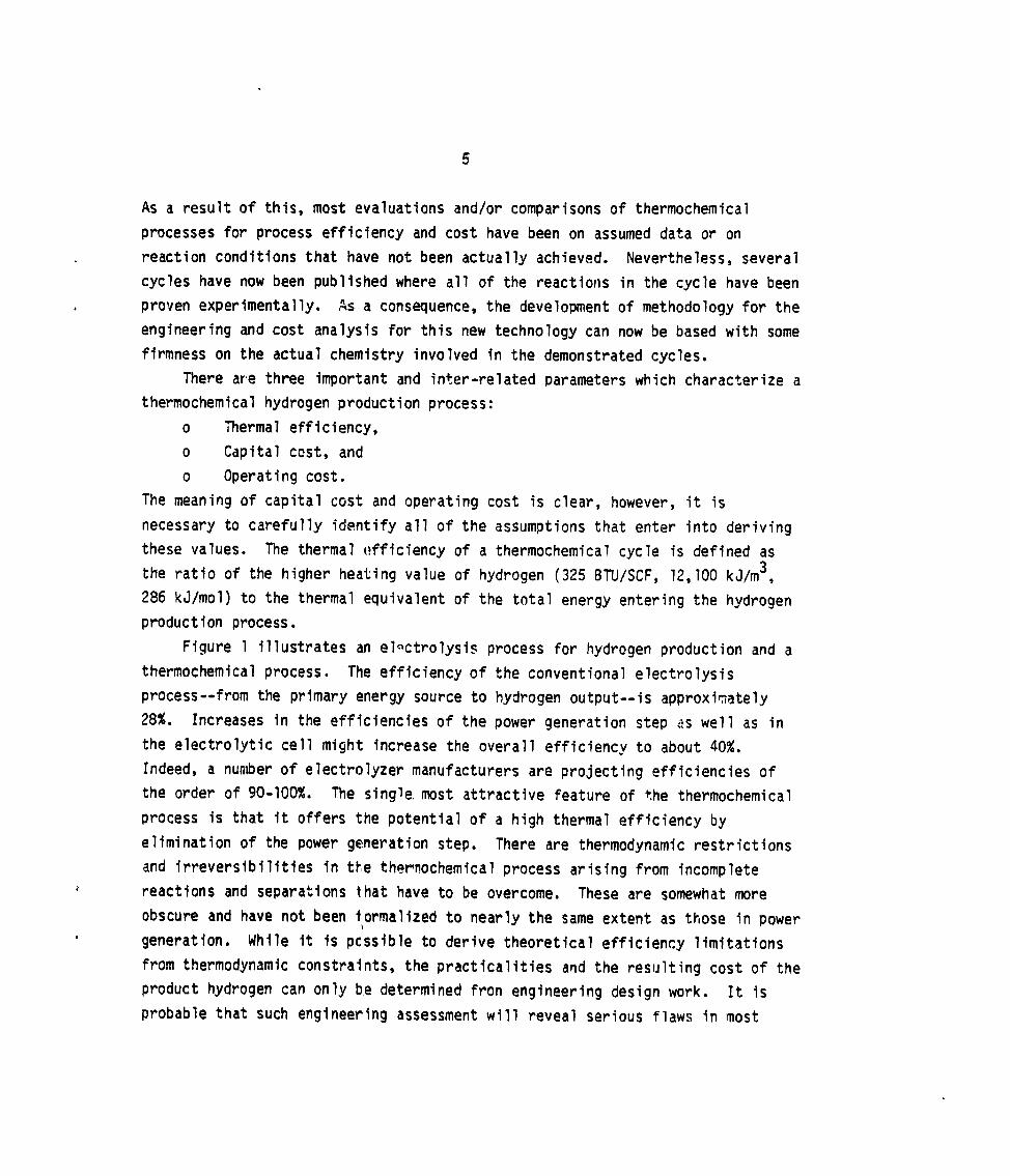
Figure 1 illustrates an el~ctrolysis process for hydrogen production and a
thermochemicalprocess. The efficiencyof the conventional electrolysis
process--from the primary energy source to hydrogen output--is approximately
28%. Increases in the efficiencies of the power generation step iiswell as in
the electrolytic cell might increase the overall efficiency to about 40%.
Indeed, a number of electrolyzer manufacturers are projecting efficiencies of
the order of 90-100%. The single,most attractive feature of the thermochemical
process is that it offers the potential of a high thermal efficiency by
elimination of the power gmeration step. There are thermodynamic restrictions
and irreversibilitiesin ttlethermochemicalprocess arising from incomplete
reactions and separations that have to be overcome. These are somewhat more
obscure and have not been formalized to nearly the same extent as ttiosein power
generation. While it is pcssible to derive theoretical efficiency limitations
from thermodynamic constraints, the practicalities and the resulting cost of the
product hydrogen can only be determined fron engineering design work. It is
probable that such engineering assessment will reveal serious flaws in most

6
cycles, but in many cases changes in process flow sheets will be possible that
will minimize the flaws. It is anticipated that this process of iterationwiil
not only yield improvements in existing cycles, but also lead to the development
of criteria to guide the search for and evaluation of newer and possibly better
(in terms of efficiency) thermochemicalcycles.
THERMOCHEMICALWATER DECOMPOSITION
In its most general sense, thermal water decomposition implies the ,
splitting of water into its elements, hydrogen and oxygen, by the use of heat.
!dater(liquid state) has an extremely high enthalpy and free energy of formation
(-286 and -237 kJ/mol) that decrease slowly as the temperature increases. For
this reason, direct or one-step processes to decompose water are impractical.
Temperatures in excess of 3000 K are required to obtain a reasonable
hydrogen and one is faced additionallywith separating this hydrogen
and the unreacted water before the p’*oductsrecombine. The reaction
favored by low pressure which is detrimental if the final product is
pipeline pressureo2
yield of
from oxygenis also
hydrogen at
To improve on direct water-splitting, researchers have tried methods that
deompose water in a number of steps. These processes, by which water is
decomposed by a set of chemical reactions at various temperatures with complete
recycling of the intermediatereactants, are known as thermochemical cycles.
ThermochemicalEfficiency
The definition of efficiency,q, adopted by the International Energy
Agency,3 is the ra+io of the theoretical energy required, 4H0, (286 kJ) to
the total heat input required, QT, for the decomposition process, based on one
mol of water. ThuS ,
.AHO=&‘~QTO
(1)
The efficiency is sometimes defined on the basis of the free energy of
formation of liquid water rather than on the enthalpy:4
AGO==n’=—QT QT ‘
(2)

7
This definition takes into account the pressures at which the gases are
produced. Under standard conditions, the ratio of the two efficiencies is 1.2:
11/TI’ =AH”/AGO = 286/237 = 1.2 . (3)
The upper limit on thermochemical cycle thermal efficiency, rI,was first
defined by Funk and Reinstrom5 as:
MO” Th-Tc11=—
AGO ~’ (4)
where Th and Tc represent the maximum and minimum temperatures in the cycle.
The cycle efficiency has an upper limit of 1.2 multiplied by the efficiency
of a Carnot engine operating between the same temperature in the cycle. For
temperatures of 1000 K and 400 K, a 72% cycle efficiency is theoretically
attainable.
The Step-Wise Decompositionof Water
The basic thermochemistry involved in the step-wise decomposition of water
was published !n 1966.5 A largeAS value is required so that the TAS term
equals thedH term for the high temperature reaction of a two-step cycle. It
was concluded that simple two-step cycles would not be feasible for the 1150 K
maximum temperature available from a nuclear high-temperaturereactor at that
time. Recently, other workers have considered the thermochemistryof water
decomposition cycles and essentially confirmed the ~onclusions of Funk and
Reinstrom. Bowman6 has repeated the analysis in order to point out that
specific values for the sum of the ASO and the AHOterms are required for
the endothermic reactions if maximum heat efficiencies are to be realized.
These values depend on the maximum tem~erature at which heat is available and
the AG~ of ;{20at the low temperature. Thus, for a general two-step
decompositioncycle:
1, R+AB+RA+
2. RA+R+AatB at 11,
‘2“
8
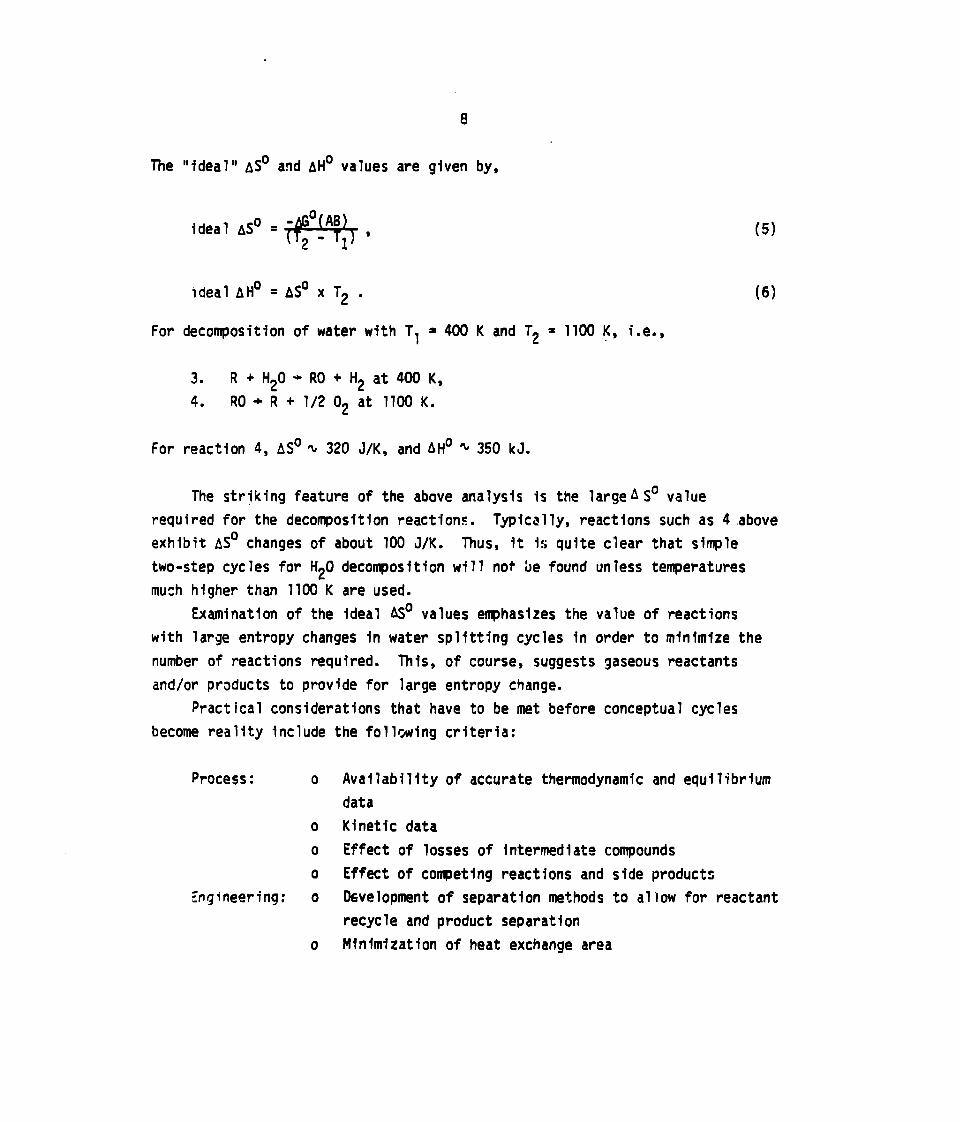
The “ideal” ASOand AHOvalues are given by,
ideal ASO‘** (5)
(6)IdealAHO=ASOXT2.
For decompositionof water with 11 = 400 K and T2 = 1100 K, i.e.,
3. R+ H20+RO+H2at400K,
4. RO + R + 1/2 02 at 11OO K.
For reaction 4, ASO k 320 J/K, and AHO ~ 350 kJ.
The strjking feature of the above analysis is the largeASO value
required for the deconposltion reactions. Typically, reactions such as 4.above
exhibit ASO changes of about 100 J/K. Thus, it Is quite clear that simple
two-step cycles for H20 decomposition will not be found unless temperatures
much higher than 1100 K are used.
Examination of the ideal AS” values emphasizes the value of reactions
with large entropy changes in water splitting cycles in order to minimize the
number of reactions required. This, of course, suggests gaseous reactants
and/or pr~ducts to provide for large entropy change.
Practical
become reality
process:
considerations that have to be met before conceptual cycles
include the follmving criteria:
o Availability of accurate thermodynamic and equilibrium
data
o Kinetic data
o Effect of losses of intermediatecompounds
o Effect of co~etlng reactions and side products
Engineering: o 06velopment of separation methods to allow for reactant
recycle and product separation
o Minimization of heat exchange area

9
0 Materials to withstand high temperature and hostile
environments
These are the primary reasons why cycles have not yet been developed
conunerciallyalthough three ‘laboratory-scale’modeis have been set up at this
time. Mention has already been made of the large amount of scientific activity
ii; this field; much of it is devoted to laboratorytesting of the key re~ctions
and to engineering evaluation of the cycles undergoing examination.
THERMOCHEMICALCYCLES UNDER ACTIVE RESEARCH AND DEVELOPMENT
Resea(ch programs in the United States and abroad (Europe, Japan) have
identified large numbers of prospective thermochemical cycles since the
inception of this technology in 1972. These cycles have been screened through a
series of laboratory and preliminary engineering/economictests to determine
their potential for further effort.
Support for cycle development has been granted by both government agencies
(DOE, in particular) and by private industry. At present, cycles must show
economic competitivenesswith other cycles under development as well as with
conventional and future electrolysis schemes in order to obtain funding. The
economic analysis that ultimately determines product cost starts with a detailed
engineering flow sheet based on (reliable) laboratory data. Workable separation
schemes for prccess and product streams are required for product recycle and
recovery. Kinetics and reaction yield obtained in the laboratory define the
sizes and configurationcf the needed chemical reactors as well as the amount of
chemical inventory on hand. Heat exchange, an important factor in determining
cycle efficiency, must be optimized both for heat recovery and minimization of
heat exchange surface area. The cycle process efficiency is an important
parameter that may be used, with due care, to monitor the effect of changes in
process conditions and of other variables, such as alternate separation
processes.
Three cycles, not necessarily the “best” ones, have survived the screening
process and are presently being tested in continllous-circljitbench-scale units.
Typically, these units are designed to produce hydrogen at a rate of 2
liters/rein(4.25 SCF/hr) and use recycle chemicals. The basic purpose of the
bench-scale tests is
information on cycle
The cycles are:
o Hybr:d sulfuric
o Sulfuric acid -
0 Hybrid sulfuric
10
to demonstrate “operab<
efficiency and cost.
lity” rather than to obtain ser”ous
acid cycle - (Westinghouse/EuratomMark 11)
hydrogen iodide cycle - (General Atcmic/Euratom Mark 16)
acid - hydrogen bromide cycle - (Eurat.omMartk13)
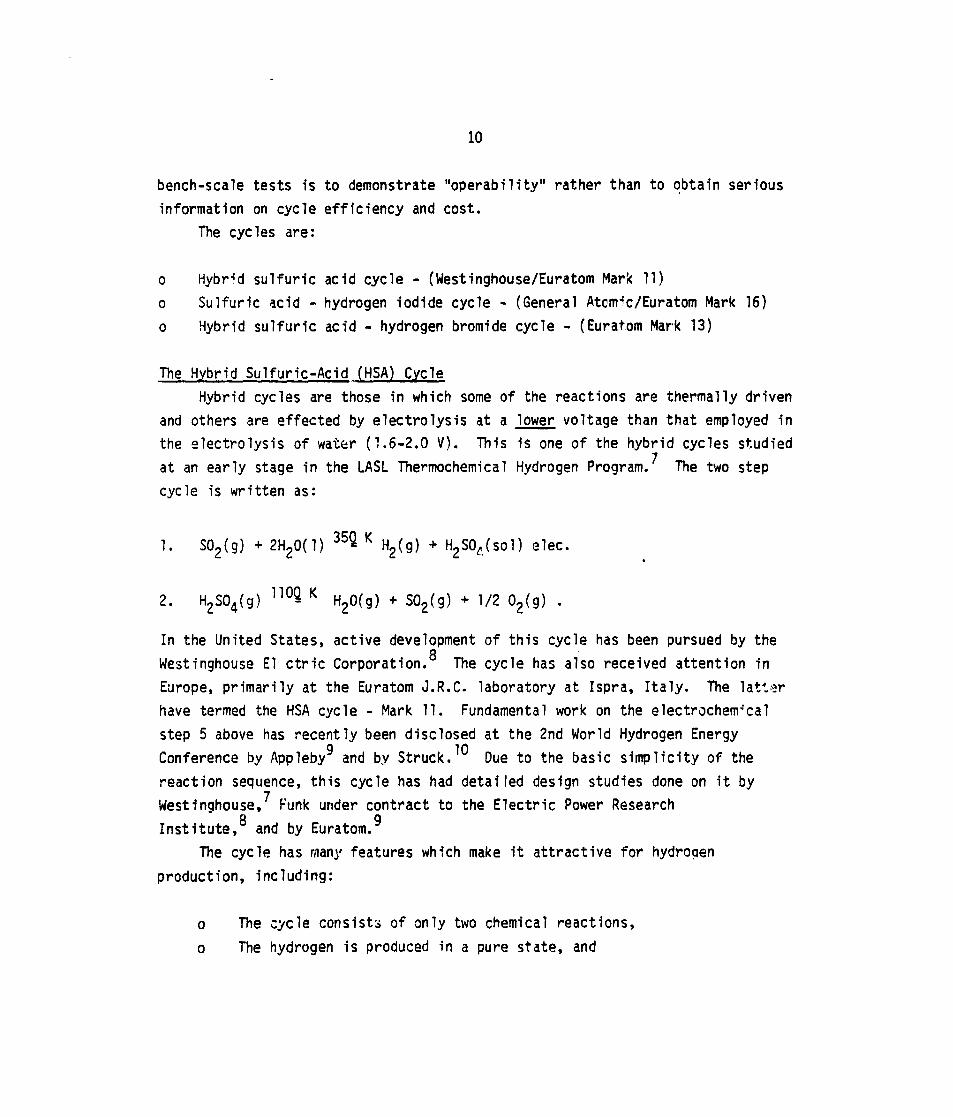
The Hybrid Sulfuric-Acid (HSA) Cycle
Hybrid cycles are those in which some of the reactions are thermally driven
and others are effected by electrolysis at a
the electrolysis of water (1.6-2.0 V). This
at an early stage in the LASL Thermochemical
cycle is written as:
10 S02(g) + 2H20(1)
2. H2S04(g) ’10~ K
In the United States,
Westinghouse El ctric
lower voltage than that employed in
is one of the hybrid cycles studied
Hydrogen Program.7 The two step
35~K H2(g) + H2SOL,(S01)elec.
H20(g) +so2(g) + H+(g) .
.
active development of this cycle has been pursued by the
Corporation.8 The cycle has also received attention in
Europe, primarily at the Euratom J.R.C. laboratory at Ispra, Italy. The Iattsr
have termed the HSA cycle - Mark 11. Fundamental work on the electrochemical
step 5 above has recently been disclosed at the 2nd World Hydrogen Energy
Conference by Applebyg and by Struck.10 Due to the basic simplicity of the
reaction sequence, this cycle has had detailed design studies done on it by
Westinghouse,’ Funk under contract to the Electric Power Research
Institute,g and by Euratom.9
The cycle has many features which make it attractive for hydrogen
production, including:
o lle cycle consists of only two chemical reactions,
o The hydrogen is produced in a pure state, and

11
0 All reactants and products are either in the liquid or in the gas
phase.
A simplified flowsheet of the process is given in Fig. 2. The cycle can be
divided into four major sections: the electrolyzer, the acid concentrator, the
acid decompose, and the separation system.
In the electrolyzer system, sulfur dioxide is mixed with makeup and recycle
water. This solution is.transferred to the anode side of the electrolyzer in
which approximately50%of the sulfur dioxide is oxidized to sulfuric acid,
while hydrogen (99.9%) is evolved at the cathode. Sulfur will be produced at
the cathode if sulfurous acid migrates from the anode to the cathode
compartment. This will result in a loss of faradaic efficiency for hydrogen
generation for the cell. TO prevent migration of sulfurous acid, a membrane ~s
placed between the two electrode compartments and a slight electrolyte
overpressure is maintained in the cathode compartment. The membrane and
overpressure cause an increase in the cell internal resistance and a net flow of.
slufuric acid from the cathode to the anode compartment.’ Subsequently,the
sulfuric acid stream is purged of sulfur dioxide and sent to the acid
concentrator.
In the earlier Westinghouse designs,11 an acid concentrator section was
not included as the electrolyzer effluent was at 75 or 80% acid (by weight).
Serious doubts as to whether electrolysis can be performed at these high
concentrations have been raised by both Applebyg and Struck.10 In their
opinion, 55% acid is the highest concentration practical in this application.
In all likelihood,therefore, an acid concentrator section, possibly a
multiple-effectevaporator, will be required to concentrate the acid from 55% tc
the 75-80% design basis or further to the 98% azeotrope.
The decomposition system consists of the equipment required ‘o decompose
the acid into sulfur trioxide and water, and thermally reduce the sulfur
trioxide to sulfur dioxide and oxygen. The acid from the concentrator is
preheated and further concentrated to greater than 98% (azeotropiccomposition)
by contact with the hot effluent of the acid decompose and vaporized in the
acid vaporizer section. The gas mixture enters a connectively heated catalytic
reactor where the decompositionproducts, water, undecomposed sulfur trioxide,

12
su?fur dioxide and oxygen result. On removal of the undecomposed sulfur
trioxide and part of the water, this gas mixture is sent to the sulfur
dioxide-oxygen separation system.
Water and the remaining sulfur dioxide can be removed by several
conventional separation schemes. Compression and cooling is the scheme adopted
in the Westinghouse design. Ispra is testing a gas adsorption scheme using
activated charcoal as the adsorbent species. The purified oxygen is vented to
the atmosphere and sulfur dioxide is returned to the electrnlyzer portion of the
process.
A complete description of the Westinghouse design may be found in recent
t-eports8’36with efficiency and economics. III their Case 3, utilizing a Very
High Temperature Nuclear Reactor (VHTR) rated at 2790 MW(t) producing 380
x 106 SCFIIof hydrogen, an efficiency of 54.1% overall was obtained. An
earlier study, published as NASA CR-134976,11 arrived at an efficiertcyof
45.2%. An EPRI report authored by Funk quotes an efficiency of 44% using the
same design bases (compare to 45.2%).12 The 44% efficiency was obtained by
the Lummus Company. The Euratom Laboratory using a different design basis than.Westinghouse, i.e., 100,OOO m$/hr of hydrogen (roughly 1/4 the Westinghouse
size) arrlvt?dat an overall thermal efficiency of 41.4%. In this autho}”s
opinion, the design bases were somewhat “over-optimistic”as regards the
performance of key plant facilities, especially
reality, with the use of actual laboratory data
would be below 40%. The efficiency/cost valu~s
section of this report.
the
for
Wfl’
Funding for the development of this cycle is bc
electro!yzer unit. In
design, the plant
be reviewed in a
ing o~.ained from
effic
later
DOE
primarily, OOE-Solar is s’4pportingsome work in the sulfur trioxide
decomposition area. Cnrporate funding is also being applied to the
laboratory-scalefacility that will illustratethe “proof-of-concept”
cycle.
ency
for this
Construction of a continuous closed-cycle bench-scale unit is ongoing with
a scheduled start of operation by November 1978 at the Westinghouse Advanced
Energy Systems IXvision’s laboratory in Pittsburgh, Pennsylvania.

13
Key Problem Areas - Hybrid Sulfuric Acid Cycle
Electrolyzer - Operating voltage, cur’rentdensitv and effluent acid
concentration. These parameters will bear heavily on the
cycle efficiency/cost.- Electrode materials, should be inexpensive and
long-lasting. Presently, carbon electrodes with platinum
loading.
Cell construction, to withstand 30 atm operating pressure
and temperature in the 50-80 C range.
Acid concentrator and vaporizer - No reference materials for these units have
been identified. D~riron and Durichlor have been
suggested, but both are difficult to form and expensive.
Capital cost estimate - fii~ is deemed inaccurate for two reasons. One, the
design basis was predicated on a highly idealized
conceptual design of the process (using overly optimistic
assumptions as to operating data), and two, materials are
as yet unidentified and thus costs are difficult to
determine. Using typical chemical engineering estimating
methods, based on the cost-factor approach, it is
approximated that the total ?nstalled cost may be 1.5 to
3 times that presented.
In a positive light, one might add that this cycle is one of the “best” of
those under present-day development and that there is sufficient evidence to
state with considerable confidence that this process can be made workable
technica~?y. The process design is acceptable from the point of view cf
feasibility. The various steps in the cyclL Ie been demonstrated in the
laboratoryor are well known in the chemical i,,~stry. However, if the proposed
plant were to be built with current technology, the system could be made
operable but the cost of hydrogen would be higher than that derived from the
optimisti: economics given by Westinghouse.
The Sulfurlc Acid Hydroqen iodide Cycle
This cycle differs from the others under development in that it is a “pure”
thermochemical cycle. No electrolytic steps are included. A cycle with the
same chemical steps is undergoing evaluation at the Euratom Laboratory, Ispra,

14
Italy, and has been named the Mark 16 thermochemical cycle there. In the United
States, its development’fs being conducted by the Genera? Atomic Company
(GA).13
This water-splittingprocess consists of the three fo!?owing chemical
reactions:
30~K H2S04(S01) +2 HIX(SO1)1. 2 H20(1) + S02(g) +X12
60~KH2(g) + x12(g)2. 2HIx(g)
H2s04(g) “O~K H20(g) + S02\g) + 1/202(9)3.
The first reaction is conducted at around room temperature in aqueous solutlon.
Use of excess iodine by GA, or of excess sulfur dioxide by Euratwn, causes the
formation of two distinct liquid phases which can be separated by recantation.
The lighter phase is predominantly sulfuric acid and the heavier (lower) phase
contains the HIX. “
By itself, the second reaction is relatively straightforward,however,
conversions are low (roughly 20%) at the temperatures indicated,600-700 K, for
rapid reaction kinetics. The separation of HIXfrom the aqueous heavy phase
of the first reaction is complicated b~ the formation of a HI-water azeotrope.Phosphoric acid, H3p04, is used as an azeotrope breaker forming a
preferential aqueous solution that must be evaporated.
The final reaction in this cycle is chc:decomposition of sulfuric acid that
is common to this and the previous cycle under discussion. Concentration o? the
acid is done by mu’
thermal efficiency
A schematic d
and sulfur dioxide
tiple-effect flash evaporation in order to improve the
and matchup with the heat source.
agram of the process is given in Fig. 3. The water, iod-ne,
enter the low-temperature(368 K) reactor where the two
liqufd phases are formed. The lower phase of this reaction, containing the
HIX aqueous solution, is sent to a vacuum still and desu?fur:zer to remove
trace sulfur dioxide and sulfur. After concentration and recovery from aqueous
solution, ths hydrogen iodide iS thermally cracked to give hydrog~n and iodine

vapors. The iodine is
reactor leaving a pure
then vaporized at about
thermally decomposed in
oxygen. General Atomic
directly into the first
t
I
15
:ondensedfrom this stream and recycled to the first
~ydrogen product. The sulfuric acid is concentrated and
98% acid. The sulfur trioxide in this stream is
a catalytic reactor to produce sulfur dioxide and
has discovered that this gas mixture can be passed
reactor to effect the separation. The sulfur dioxide
takes place in the reaction and oxygen passes through without effect and is
vented to the atmosphere. This obviates the need for a separate sulfur
dioxide-oxygen separation step.
The cverall process efficiency, as determined from an early flowsheet
prepared by the Lummus Company, was 36.2%.12 A later flowsheet, prepared and
analyzed by GA, and quoted in the EPRI report, indicates an efficiency of
41.4%. In late 1978, with 60% of the latest flowsheet optimized, CA expects an
efficiency in the neighborhood of 45% or higher for their cycle.‘3 This in
turn contrasts with the Euratom estimate for the Mark 16 flowsheet of
approximately 40%. An independentestimate of the Mark 16 flowsheet made by the
Chemical Engineering se:;ion of the Belgian SCK/CEN Laboratory gives a value of
31% for the efficiency. Energy consumption due to the product separation
steps, for example HI decomposition; leads to this value.
As with Westinghouse, GA hopes to have in operation a continuous,
closed-circuit laboratory-scaleunit of their process in operation by the end of
1978. GA is recefving funds from the Gas Research Institute (GRI), DOE, and
corporate sources to develop this cycle.
Key Problem Areas - Sulfuric-Acid Hydroqen Iodide Cycle
Main solution reaction - Degassing of the sulfur dioxide from the
solutions. Elimination of the oxygen effluent without loss of Intermediate
species, sulfur dioxide or iodine. Handling and recovery of large quantities of
iodine are required,
Acid concentration - Tradeoff between amount of heat recovery and cap’tal
cost. In the GA flcwsheet, SIX flash evaporation stages are called for to
concentrate sllfuric acid from 55% to 98%. These are highly capital-intensive.
Materials are a major consideration here as boiling sulfuric acid is being
handled.
16
Aydroqen iodide recovery and decomposition - Phosphoric acid is used to
separate the HI-H20 azeotrope. The resulting phosphoric acid solution must be
distilled resulting in a heat penalty for the process. Hr decompositionmay be
improved by use of a catalyst that allows iodine to be recovered in the liquid
state.
GA concludes that this cycle appears to be a promising approach to
producing hydrogen from non-fossil sources matching the thermal output
capability of the High Temperature Gas-Cooled Reactor (HTGR) rather well.13
The all-liquid and gas phase characteristicsof the cycle are claimed to give
this cycle a considerable advantage o~er cycles requiring solids handling. This
last point has not been verified, however.
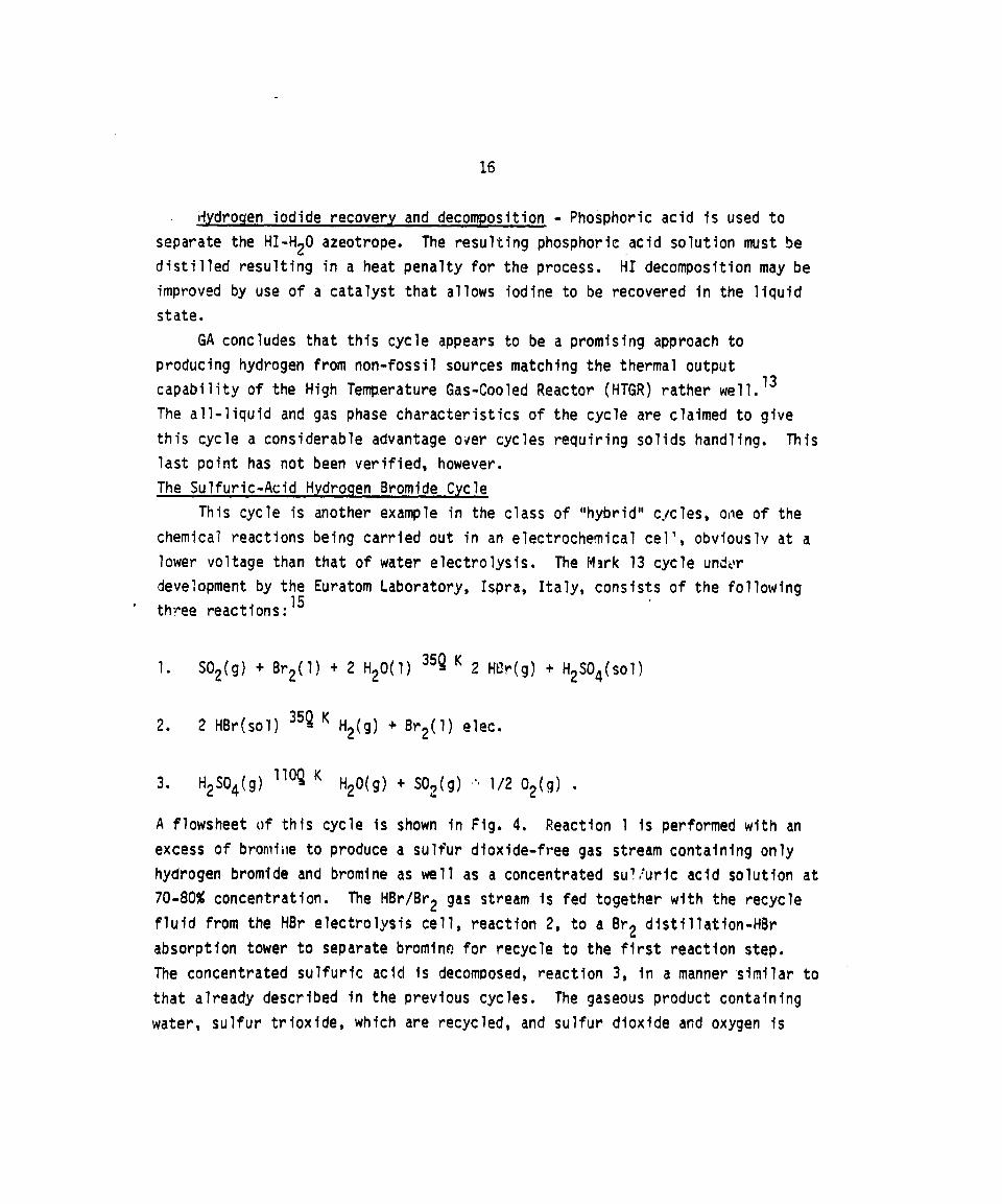
The Sulfuric-Acid Hydroqen Bromide Cycle
This cycle is another example in the class of “hybrid” eye’
chemical reactions being carried out in an electrochemicaleel’,
lower voltage than that of
development by the Euratom“ th~ee reactions:15
es, one of the
obviouslv at a
water electrolysis. The Mark 13 cycle undvr
Laboratory, Ispra, Italy, consists of the following
35~K 2 HUr(g) +H2S04(S01)1. S02(g) + Br2(l) + 2 H20(1)
35~K H2(g) +Br2(l) elec.2. 2 HBr(sol)
H2$04(g) “O~K H20(g) + $02(g) o“1/2 02(g) ●3.
A flowsheet of this cycle is shown in Fig. 4. Reaction 1 is performed with an
excess of bromiiieto produce a sulfur dioxide-free gas stream containing only
hydrogen bromide and bromine as well as a concentrated su?:uric acid solution at
70-80% concentration. The HBr/Br2 gas stream is fed together with the recycle
fluid from the HBr electrolysis cell, reaction 2, to a Br2 distillation-HBr
absorption tower to separate bromino for recycle to the first reaction step.
The concentrated sulfuric acid is decomposed, reaction 3, in a manner similar to
that already described in the previous cycles. The gaseous product containing
water, sulfur trioxide, which are recycled, and sulfur dioxide and oxygen is

17
then separated to recover sulfur dioxide. The oxygen, as before, is vented to
the atmosphere. In the electrolytic cell, the entering
HBr solution practically free of bromine. The effluent
4% bromine. The inlet HBr concentration to the cell is
decreases to 41%.
fluid consists mainly of
contains approximately
45% and at the outlet
Designs on this cycle have been performed at Euratom to obtain efficiency
and
key
the
hydrogen cost. The cell voltage for the electrolytic step, reaction 2, is a
parameter in the process. Laboratory work has indicated a cell voltage in
range of 0.8-1.0 V at a current density of 2000 Am-2 at the HBr.-16 Using a value of 0.8 V for the electrolyzerconcentrations indicated above.
voltage, an efficiency of 37.2% was obtained fcr this cycle.17
A complete, continuous, closed-cycle laboratory-scaleunit operating at 100
liters/hour (4 mo? H2/hr) is now in operation at the Ispra facility of
Euratom. Th;s unit is the first working model of a hybrid thermochemical
process in the world and, as such, represents a new frontier in hydrogen energy
technology. The aims of this plant are to study the following:
o Whether the reference design conversions and reactant concentrations can be
achieved and maintained.
o Testing of control and analytical equipment under actual, corrosive
conditions.
o Determinationof possible by-product formation and developing suitable
remedies.
o Obtairtlng
Observ&tion of
indicated t~lat
data for plant scale-up.
the plant in operation during a visit to Ispra in August 1978
most of the above objectives were being met, Hydrogen was being
produced in the unit and the HBr/Br2 streams were being recycled and reused
without significant loss or by-product formation. A novel feature of the plant
was the use of a membrane?ess electrolyzet’to cut down orilosses due to internal
cell resistance. At the ttme of the visit, this electrolyzer was operating at a
vo?tage higher than the 0,8 V design specification,however this was to be
remedied by the use of an electrolyzer of newer ar,dbetter design (as regards
electrode materials, configuration, flow passages, etc.).

18
Key Problem Areas - Sulfuric-Acid Hydrogen Bromide Cycle (Mark 13)
Electrolyzer - Operability at design conditions of 0.8 V or less. The
electrical requirements of this cycle are rather severe as 0.8 V is
appro~imately half the voltage requirement for water electrolyzers using
advanced technology, such as the GE SPE electrolyzer. This problem may be very
difficult to overcome; it also has a large effect on the efficiency.
Materials - for containment of the HBr and Br2 species.
ALTERNATIVE CYCLES UNDERGOING ACTIVE RESEARCH
A selection of two of the cycles under experimental research was made. The
cycles chosen were the Los Alamos Scientific Laboratory (LASL) Bismuth Sulfate
Cycle and a Japanese cycle known as the Magnesium-IodineCycle. Thei+eare many
other cycles being actively pursued at other laboratoriessuch as the Institute
of Gas Technology,18,33 Argonne National Laboratory,‘g Oak Ridge National
Laboratory,20 and the Lawrence Livermore Laboratory21 in the USA alone. The
cycles are shown in Table 1A and B. However, it was felt that preliminary data
on these cycles indicated either a Iowefficiency or a low promise of
commercialization,
The LASL Bismuth Sulfate Cycle24,25
We have seen in previous sections that sulfuric acid is z convnon
denominator to the hybrid cycles as well as to the GA cycle. Sulfurfc acid
poses serious problems, both in its handling whfch requires materials resistant
to corrosion as well as in its concentration to the azeot]$opiccomposition,
98%. The latter step involves evaporation of sulfuric acid solutions. Th
operation incurrs a l~rge heat penalty unless the latent heat in the vapor
recovered. Multiple effect evaporation may accomplish this recovery but,
doing so, adds largely to the capital cost ofthe plant.
s
is
n
Avotdance of these problems can be achfeved by the use of an fnsoluble
metal sulfate that is precipitated from the sulfurlc acid solution. To be most
efficient, the metal sulfate should additionally not possess water of
hj’dration. Bismuth sulfate was found to have the desired properties and the
cycle thus formed Is shown below:
35~ K H2S04(S01) + H2(g) elec,1. S02 +2 H20(1)

19
35~ K l/3Bi203”3S03 + H20(1)2* H2S04(S01) + 1/3 Bi203(s)
90°-l~OcK l/3 Bi2(+(s) + S02(9) + ~/2 02(9) ●3. l/3Bi203’3S)3(s)
A flowsheet of the cycle is seen in Fig. 5. The bismuth sulfate precipitates on
adding bismuth oxide to the sulFuric acid produced in the electrochemical step,
reaction 1. In this manner,sulfur trioxide is recovered from the sulfuric acid
w;t!?outthe need for a costly and corrosive acid drying step. In addition, use
of the bismuth sulfate or a bismuth oxysulfate may allow the electrochemical
reaction to proceed at a lower ac;d concentration than 55% or higher required in
the hybrid sulfuric acid cycle, possibly lowering the voltage requirements and
therefore improving the efficiency of this cycle.
Preliminary calculations based on these effects shows a potential 10.12%
efficiency improvementwhm solid sulfate processing is substituted for sulfuric
acid in these cycles. The major challenge is to devise the means @f handling
large quantities of solids and process them at high temperatures (1000-1500 K).
Bismuth sulfate, Bi203 3S03 or Bi2(S04)3, decomposes with
increasing tenmerature to a series of bismuth oxysulfates and sulfur trioxide.
The latter in turn decomposes to sulfhr dioxide and oxygen as shown:
4. Bi20303S03(S) = Bi20302S03(S)+ $03(g)
5. Bi203*2S03(S) ~i203*S03(S)+ S03(g)
6. Bi203°S03(S) = Bi203(s) + ‘03(9)
7. S03(9) =s02[7) + l/202(g) .
As a result, the opt ons for generating S03 over a
includes intermediatetemperatures, in addition to
temperature range that
higher temperatures for S03
deconpositlonexist, and should be useful in achieving efficient extraction of
heat from a HTGR, a fusion reactor or a solar heat source,
A laboratory-scaleunit to test the decomposition of bismuth sulfate is
being designed at LASL with operation contemplated for later in 1979. Initially

20
electrical heating will be used with plans to implement the heating with a solar
source later. To avoid the circulation of large quantities of bismuth sulfate,
it is proposed to heat and decompose sulfur trloxide. The product sulfur
dioxide and oxygen will recombine in another section of the chemical reactor
giving up its thermal energy in the form of exothermic hezt of reaction. We
hope to try this new concept of a “chemical heat pipe” as an efficient method
for heat transfer in the unit co be built later this year. The unit will be
sized at approximately 100 liters/hr to be comparable in size and output with
the other bench-scale units under construction, presently.
Key Problem Areas - LASL Bismuth Sulfate Cycle
Decompose - In general, the major unknown in this cycle is solids
handling. The bismuth sulfate must be decomposed to yield bismuth oxide and
sulfur trioxide. R~action rata and heat transfer to th,esalid phase must be
rapid. The mechanism of heat transfer by use of a “chemical heat pipe” to avoid
the circulation of large amounts of gases must be proven. The configuration of
the solids decompose, i.e., fixed bed, moving bed, or fluidized bed must also
be selected and verified.
Electrolyzer - Electrolysis at significantly lower voltages (in dilute acid
solution) must be demonstrated; the electrochemical reaction must also be tested
to determine the effect of the low concentration of bismuth ion oresent in the
solution.
The Magnesium-IodineCycle (Japan)
This cycle comprising four thermal steps may be carried out at temperatures
around 900 K or below. It is being investigatedby the National Chemical
Laboratory for Industry in Tokyo, Japan. The chemical reactions included in the
present cycle are represented as follows:26
45~K 1/5 Mg(103)2(s) +Mg12(sol)1. 6/5 MgO(s) +6/5 12(s)
‘OQK 1/5 MgO(s) + 1/5 12(g) + 1/202(9)2. 1/5 Mg(103)2(s)
~ 6 H20(s) 70~KMgO(s)+2 HI(g) +5 H20(g)3. Mg12
21
600-~oo K H2(g) + 12(9) ●4. 2 HI(g)
The cycle is similar in many respects to a calcium-iodine cycle that was
reported earlier by the authors.27 The cycle flowsheet 1s shown on Fig. 6.
In this cycle, redox reaction 1 of iodine with magnesiurfloxide in aqueous
solution forms magnesium iodide in tbieaqueous phase and the iodate as a
precipitate. T!lermaldecompositionof the magnesium iodate results in magnesium
oxide, iodiru and oxygen in reaction 2. Hydrolytic decomposition of magnesium
iodide into more magnesium iodide and hydrogen iodide follows with the final
reaction 4 being the thermal dissociation cc hydrogen iodide into product
hydrogen and recycle iodine. Experiments have proven the validity of this cycle
in good agreement with thermodynamic estimatks. Disadvantages ;n the cycle with
calcium showed an exce:s of water used to obtain a high degree of reaction 3 as
well as melts of calcium oxide forming in reaction 2. These difficulties were
partly remedied by the substitutionof magnesium for calcium in the cycle. In
addition, the temperature for reaction 2 is lowered from 1100 K to 900 . with
the rates of reactions 2 and 3 being speeded up.
Cycle efficiencies for this type of cycle are not expected to be high
largely as a result of having to handle chemical species in solution which
involves the use of large amounts of low-temperature,thermal energy for drying.
In addition, the final reaction 4, decomposition of HI is energy-inefficientdue
to the separation problems involved and low conversion. An estimate of the
efficiency for this cycle is in the 20-30% r~nge, based on results for the
similar calcium-iodinecycle.20
Key Problems in the Magnesium-Iodine Cycle
Reaction 1 - Both magnesium iodide and magnesium iudate are formed in this
reaction with the latter precipitating. Practical problems are the degree of
completion of the reaction, the volubility of the iodate, and evaporation of the
solution to recover the hydrated magnesium iodide species.
Reaction 2 - Although not shown, the magnesium iodate is actually a
magnesium iodate tetrahydrate, this involves driving off the water of hydr?<ion
and more importantly,recovering their latent neat cf vaporization in an
energy-efficientcycle.
22
Reaction 3 - The problem is similar, six waters of hydration have to be
removed in addition to supplying the endothermic heat tor decomposition of
magnesium iodide.
Reaction 4 - Separation
iodide must be effected.
With these difficulties
of hydrogen from iodine and undecomposedhydrogen
and the need to evaporate large amounts of water in
this cycle, it is doubtful if this cycle wilJ be competitive with the previously
mentioned cycles. The chemical studies being done will, no doubt, contribute to
a greater understandingof cycles involving solution chemistry.
The Japanese have also proposed a cycle in which a mixture of barium and
magnesium oxides are reacted with iodine in the first reaction. The
barium/magnesium-iodinecycle may offer some interestingpossibilities that have
not yet been determined.
HEAT PENALTY ANALYSIS OF tHERMOCHEMICALCYCLE
A key parameter associated with any thermochemicalprocess is the
efficiency,q, that is redefined below.
Process Thermal Efficiency,n =4 ,QT
where AH= total enthalpy associated with hydrogen produced, and QT = total
thermal energy required frum primary energy source to produce the hydrogen.
The value of AH is 68.3 kcal/mol (286 kJ/mol) for all cycles and QT
includes all the heat and work energy required by the process. Since AH is
constant, the value of the efficiency clearly depends on
compute QT.
It appears obvious that the most accurate method of
efficiency is that of conventional chemical engineering.
is drawn up based on the chemical reacticns in the cycle
the method used to
obtaining the cycle
A complete flowsheet
and the separations
required. Heat and mass balances are then used to calculate the process
efficiency. This method is not amenable to a quick determination and thus early
efforts in thermochem~cal hydrogen were spent in obtaining a rough estimate of
this parameter for the purpose of cycle selection.

23
A computer program,
the direction of Funk to
HYDRGN, was written at the University of Kentucky under
estimate the efficiency in a uuick and rather simple
fnanner38 The HYDRGN program used thermodynamic data for the pure components
involved in each chemical reaction to calculate enthalpy, entropy, and free
energy changes for each reaction step as well as for the heating and cooling
steps in the cycle. A heat exchange routine determines the net heat by
balancing the endothermic requirements against the exothermic heat liberated in
the process. finally, the program
used in evaluating the process.
The estimate used is shown in
heat matching. The heat needed by
heats remaining after the matching
from the ideal work of separation,
calculates the efficiency estimates which are
the equation below, and is obtained after
the cycle, Q’, is the sum of the endothermic
process. The work of separation, calculated
is reduced by the work that can be generated
by unmatched exothermic heat and it is further assumed that the separation
processes are only 50% efficient.
2. q= Adw /0. - w
QI +.+ “●
The 0.3 figure in the denominator is the value assumed for the conversion from
heat to work (30%).
Since then, Funk a:idKnoche Iiavedevised a more sophisticated and accurate
means of determining the process efficiency and relating this parameter to
capita? and operating costs, as well as to the final production cost of
hydrogen.29330 The method, known as heat penalty analysis, is based on the
result that the hydrogen production cost is linear with the product of the heat
penalty and direct capital cost of each component or collection of co~onents
(battery)of the thermochemical plant. The heat penalties are the result of
irreversibilities,or entropy production, associated with the process equipment
and they are an indicationof the quality, from a basic thermodynamic viewpoint,
of z particular flowsheet or process design. The sum of all the heat penalties,
plus an ideal heat req~irement, is the total amount of energy, QT, required of
the primary heat source. The formalism of this methodology is indicated in the
equations below (process thermal efficiency expressed in terms of second law
effects on “heat penalties”):

24
where ~id = ideal efficiency - a function of the temperature of primary heat
source acd properties of material input and output, and [)PJ
= heat penalty
associated with the jth battery.
The heat penalty, Qp, can be related to the entropy production by 4 (heat
penalty Qp, and entropy production, s):
Tm4. Qp = ‘~ “TO*S
where To = sink temperature; where Tm is a characteristicof the primary
energy source,
5.T - Tin
T = Toutm P“ ●ln,#+}ln~‘in P Pout
Combining these expressions, we get,
where A,’ and AG are kcal/!i~H2, s is kcal/kgX-°K, and r is kgX/kg H2.
Table II shows a heat penalty analysis as performed by Funk for the hybrid
sulfuric acid cycle using highly optimistic values for tileelectrochemical
reaction parameters (80% H SO* ~, 0.45 V).
A battery in the chemical plant is usually the collection of process
eqtiipmentrequired to accomplish a necessary step in the process. The total
plant is the collection of batteries required to accomplish the overall
process. There are two importantcharacteristicsassociated with each battery -
the capital cost and the heat penalty - and trade-offs may be made among these
to minimiz’ the production cost.
For a fixed primary energy source output:

25
7. Pc = ~[K1+K2 x (Dcc)j ,j
where Pc = production cost, $/106 BTU or $/GJ; ~= process thermal
efficiency, (DCC)j = direct capital cost of the jth battery; K1 = constant
related to the cost of primary energy; and K2 = constant related to capital
recovery and operating costs for chemical plant.
Combining the expressions for the production cost and heat penalties:
8. Pc= [~+~ 2 Qpj] ●
~d~K1+K2 Z (DCC)i] .
j j
Note the importantcharacteristicsof each battery, (“l)heat penalty, Qp, and
(2) direct capital cost, DCC. The tradeoff is between capital cost and heat
penalties.
The procedure is applied to the hybrid sulfuric acid process and the
results are shown in Table III and plotted on a production cost, capital cost,
thermal efficiency diagram, Fig. 7.
Under conditions approaching reality (point X, 0.8 V), the efficiency of
the hybrid sulfuric acid process is 40% rat’er than 51%, with the hydrogen
prod~ction cost reaching $10.55/106 BTU ($-10.55/GJ).
MATERIALS
Key questions arise concerning the materials reallfl;~mentsof any
thermochemicalprocess involving sulfuric acid. The first concerns technical
feasibility: i.e., whether materials can be found to effect the vaporization and
decompositionof sulfuric acid at the relatively high temperatures needed for
the endothermic stage of these c’~cles. The second question is unique to hybrid
cycles, and is one of economics: can materials be found that are inexpensive
enough to offset by the energy savings due to the hybrid electrochemical step
relative to that of water electrolysis?
The unique materials requirements for sulfuric acid processing occur in the
acid vaporizer and S03 reduction reactor. Candidate materials for the
vaporizer that have been selected are:11 previous metals~ ceram:cs.
superalloy, and cast high-silicon irons (duriron). Conventional experience

26
with these materials do not match process requirements in three important areas:
temperature, pressure, and acid concentration. In industrialpractice with
sulfuric acid, the flow is normally from the acid to the containment wall; thus,
the vessel walls can be kept cooler than the acid itself. In sulfuric acid
decomposition,heat must be transferred to the acid, so that wall temperatures
in tne heat exchanger necessarily must be higher than in th~ebulk acid. Cu:-rent
data on sulfuric acid corrosion are limited to approximately 150 C and most have
been obtained only at atmospheric pressure.
In addition, the changing composition of the acid solution, the conversion
to a two-phase vapor-liquidmixture, and finally the superheating to a vapor in
the vaporizer section represent a diversity of chemical environments that may
require more than one containment material. The problem is further exacerbated
by the requirement that the containment material conform to a geometry which
provides efficient heat flow to the acid. It is difficult to accommodate
materials such as duriron and silicon nitride in conventional heat exchanger
designs.
In summary, the feasibility and economic aspects of materials for
thermochemicalcycles are open questions at the present state of development.
The feasibility question hinges strongly on the degree to wnich process
operating parameters (particularlytemperature and pressure) can be adjusted to
accommodatematerials capabilities. Experimental data on the corrosion and
mechanical behavior of materials must also be provided to answer this problem.
HVDROGEN pRfjfj~cT?ON - THERMOCHEMICALCYCLES OR WATER ELECTROLYSIS
Two competing methods are available for the production of massive
quantities of hydrogen for the future. These methods, thermochemicalcycles and
water electrolys~s, both employ water as the starting raw material and are
coupled to a high-temperatureheat source. Water electrolysis is a well-known
technology with present, relative po~r characteristicswhich may offer
improvement through some amount of res~arch. Most hydrogen produced in the
industrial countries of the world today is derived from hydrocarbons, indcw!,
the abundance of cheap hydrocarbons until recently, slowed efforts in the
f
devel ment of efficient electrolyzers. Less than 1% of the world’s hydrogen
su ?y derives from electrolysis which is used only where electricity generation
27
is favorable or where product purity is needed for some spl~cificapplication.
With estimated increas+s in both the efficiency of power generation and of the
electrolysis process forecast, thermochemical or hybrid cycles must achieve
higher levels of performance and cost to be competitive.
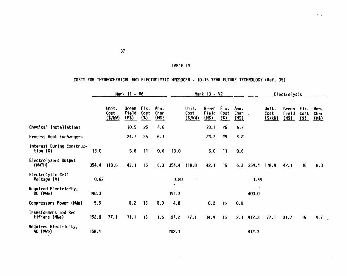
Attempts to estimate costs have been made recently at Euratom, Ispra31
and those at Westinghouse.32 The Ispra efforts have attempted to estimate the
costs of advanced electrolytic systems on par with hybrid thermochemical
cycles. As an example, using the OPTIMO code, they have calculated the hydrogen
production cost and efficiency of Mark 11, Mark 13, and Advanced water
electrolysis. Their data are shown in Table IV.
Interestinglyenough on the “bottom line,” the hydrogen production cost is
remarkably similar despite differences in the three processes. Mark 11 has
cost of $8.02/106 BTU, Mark 13: $8.88 and advanced electrolysis: $8.54.
Westinghouse has recently concluded a study for the Electric Power Research
Institute (EPRI) that indicatesmuch the same thing.32 In their work, a
comparison was made on the economics and efficiency for the hybrid sulfuric
cycle and a water electrolysis process using sulfuric acid (rather than
a
acid
potassium hydroxide) solution as the electrolyte. The two processes were based
on the same assumptions as much as possible, i.e., the same VHTR supplying
thermal energy, etc. Their results show for the thermochemical cycle a 47%
efficiency (at a voltage of 0.6 V in the electrochemicalcell and 80% sulfuric
acid) resulting in a hydrogen cost of $7.30/106 BTU. (Note: It may be
optimistic to expect hydrogen generation at 80% sulfuric acid at 0.6 V). The
water electrolysis process indicated that at a cell voltage of 1,68 V, an
efficiency of 41% and a cost of $7.80 for the product hydrogen would be obtained.
As all values are based on future technology, whictihas not yet been
developed, it is “safe” to say that thermochemical hydrogen costs are in the
same range as those for electrolytic hydrogen and hence continued R&O efforts in
both the thermochemical (pure or hybrid) and the water electrolysis areas should
proceed in parallel until one technology clearly demonstrates superiority over
the other on factual, rather than on assumed, grounds,
ECON~!MICSANO EFFICIENCY
Clearly the best method to determine the economics of a particular process
for hydrogen manufacture {s to base the determinationon a realistic flowsheet
28
of the process that in turn is based
evidence. In the case of thermochem
on a design supported by laboratory
cal hydrogen, the technology has not yet
progressed to this stage of refinement, thus cost estimates are often made based
on flowsheets put together on the basis of assumed design information. These
assumptions are made on the hope that continued research and development will
yield the desired results. This approach has the effect of yielding results
that are somewhat over-optil-,isticwhen viewed in the light of actuality.
Better estimates of the efficiency and production cost of hydrogen have
been made with the use of the Funk-Knoche heat penalty analysis ~~d the OPTJMO
computer code developed at the Euratom Laboratory, Ispra, Italy. The heat
penalty method has been described in the previous section and the Euratom
methods are shown here.
The OPTIMO code uses a modular cost estimating technique based on the
process flowsheet. The flowsheet must include al? the unit operations necessary
for the technical feasibility of the cycle and show the principal recycle
streams. The operating conditions should be fixed as a result of experimental
data or estimated carefully from thermodynamic considerations. A detailed plant
cost estimation then can be performed after definition of the process units from
the flowsheet knowing the mass flows through each unit, Knowing the mass flow
and the necessary outlet conditions, the dimensions of the individualunits can
be calculated. As an example of this procedure, the mass flow indicates the
diameter of a separation tower while the outlet conditions determine the number
of plates. Once these dimensions are found, the process unit costs may be
evaluated after materials considerations.
The
the heat
However,
the cost
the heat
key to obtaining the thermal efficiency of a thermochemicalcycle
exchange network. Heat recovery largely affects this parameter,
there is always a compromise between the amount of heat recovered
of the heat exchange surface required. It should also be evident
exchanger capital cost plays a large role in determining the total
is
and
that
plant investment. In OPTIMO, a heat recovery routine WM developed to calculate
the cost of each chemical process heat exchanger, In order to optimize the total
heat exchange network. The calculation employs the following equation:30
29
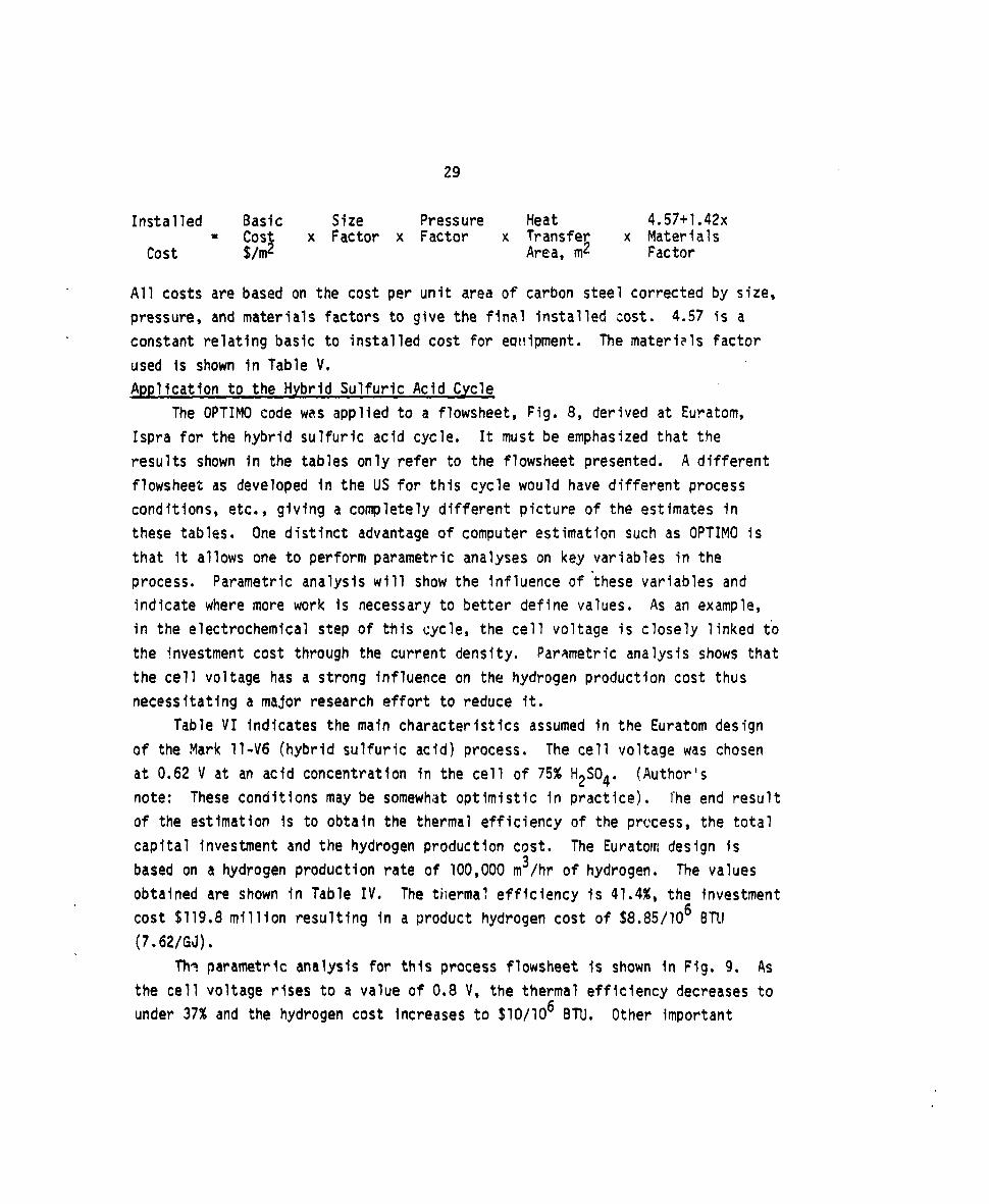
Installed Basic Size Pressure Heat 4.57+1.42x= Cos
$x Factor x Factor x Transfer x Materials
cost $/m Area, m2 Factor
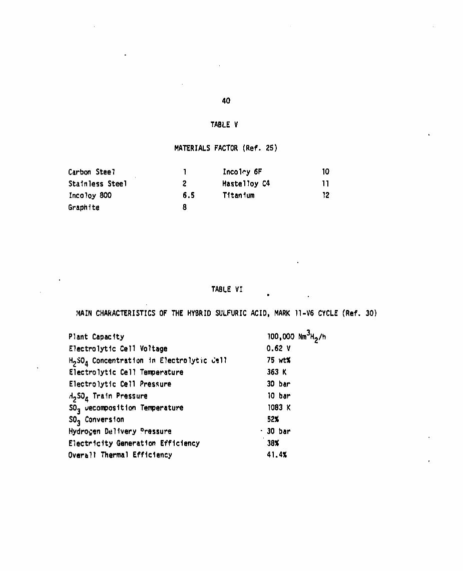
All costs are based on the cost per unit area of carbon steel corrected by size,
pressure, and materials factors to give the final installed cost. 4.57 is a
constant relating basic to installed cost for ecll!ipment.The materi~ls factor
used is shown in Table V,
Application to the Hybrid Sulfuric Acid Cycle
The OPTIMO code was applied to a flowsheet, Fig. 8, derived at Euratom,
Ispra for the hybrid sulfuric acid cycle. It must be emphasized that the
results shown in the tables only refer to the flowsheet presented. A different
flowsheet as developed in the US for this cycle would have different process
conditions, etc.~ giving a completely different picture of the estimates in
these tables. One distinct advantage of computer estimation such as OPTIMO is
that it allows one to perform parametric analyses on key variables in the
process. Parametric analysis will show the influence of-these variables and
indicate where more work is necessary to better define values. As an example,
in the electrochemicalstep of this cycle, the cell voltage is closely linked to
the investmentcost through the current density. Parametric analysis shows that
the cell voltage has a strong influence on the hydrogen production cost thus
necessitating a major research effort to reduce it.
Table VI indicates the main characteristics assumed in the Euratom design
of the Mark 11-V6 (hybrid sulfuric acid) process. The cell voltage was chosen
at 0,62 V at an acid concentration in the cell of 75% H2S04. (Author’s
note: These conditions maybe somewhat optimistic in practice). ihe end result
of the estimation is to obtain the thermal efficiency of the process, the total
capital investment and the hydrogen production cost. The Euratom design is
based on a hydrogen production rate of ?00,000 m3/hr of hydrogen. The values
obtained are shown in Table IV. The thermal efficiency is 41.4%, the investment
cost $119.8 million resulting in a product hydrogen cost of $8,85/106 BTU
(7.62/GJ).
TIW parametric analysis for this process flowsheet is shown in Fig. 9. As
the cell voltage rises to a value of 0.8 V, the thermal efficiency decreases to
under 37% and the hydrogen cost increasesto $10/106 BTU. Other important

30
variables influencing these values are the primary energy cost (cost of thermal
energy from the primary heat source), and the minim~m AT that is used in the
design of the heat exchangers. Increases in AT lead to a reduced area, hence a
decreased overall capital cost, however, the process AS is increased leading to
a lowered efficiency and greater energy requirements (for the same net amount of
hydrogen produced). These competing effscts lead to a trade-off situation;
optimization of this position gives a m’~nimumproduction cost, the position of
which depends on the relative lripc)rti~t’)ce of the cost of capital and energy.
Other investigatorshave made estimates of the energy efficiency and
hydrogen production cost for thermochemical hydrogen. Funk detailed costs for
the hybrid sulfuric acid cycle and a methanol cycle (AMor’s conwnent:
technically unworkable), in an earlier EPRI report.12 Another appraisal of
these variableswas done in a similar study by Westinghouse for the same
cycle.8 In addition the Euratom Labora~~ry has performed an analysis using
the OPTIMO code on their Mark 13 cycle. These data have been collected in
Table VII and are plotted on Fig. 10, The data from the table and plot show a
minimum cosl11report, a
These costs
electrochem’
in the near
reaction).
of $4.90/106 BTU at 45% efficiency from an early Westinghouse
later report gives the cost as $5.56 at an efficiency of 54%.8
and efficiencies were obtained for certain assumed conditions in the
cal reactiun that have not been, and are not likely to be achieved
future (as a result of fundamental chemical mechanisms in the
A recent Westinghouse ~eport32 comparing the techno-economicsof
the hybrid sulfuric acid cyc?e with that of sulfuric acid (water) electrolysis
using a more realistic voltage of 0.6 V arrives with an efficiency of 47% at a
hydrogen cost of $7.30/106BTU. In comparison, their assessm~nt of the water
electrolysis, of which more will be added in the next section, comes to a 41%
efficiency at a cost of $7.80.
The maximum cost is for the Lawrence Livermore Laboratory Zinc-Selenium
cycle indicating a $13950 cost at 42% efficiency.21 Part of the reason for
the high cost for this cycle is a result of a large amount of material
circulation, mainly water, hence capital intensive. The design was also based
on laboratory data rather than on as~umed conditions, which affects the
flowsheet desig~’and ultimately the hydrogen cost.
From the da~a presented, it appears likely that a successful thermochemical
hydrogen process will have a thermal efficiency in the 40-45% range with the
31
cost of product
lower than this
hyd~ogen being in the $8.00 to $10.00/?06 BTU bracket. costs
will result if there is a drop in the cost of the primary heat
source and/or capital equipment, both of which are very unlikely to happen.
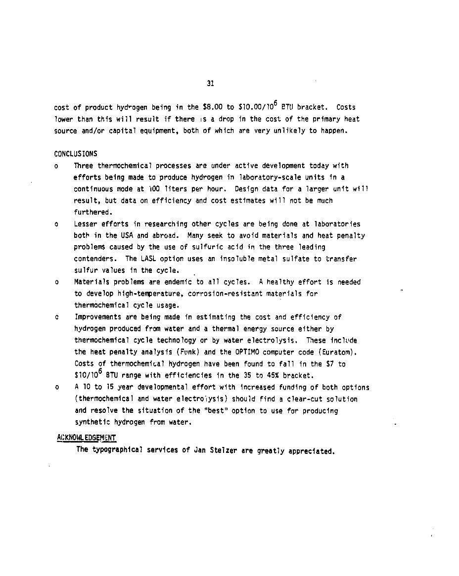
CONCLUSIONS
o
0
0
0
0
Three thermochemicalprocesses are under active development today with
efforts being made to produce hydrogen in laboratory-scaleunits in a
continuous mode at ‘1OOliters per hour. Design data for a larger unit will
result, but data on efficiency and cost estimates will not be much
furthered.
Lesser efforts in researching other cycles are being done at laboratories
botb in the USA and abroad. Many seek to avoid materials and heat penalty
problems caused by the use of sulfuric acid in the three leading
contenders. The LASL option uses an insoluble metal sulfate to transfer
sulfur values in the cycle. .
Materials problems are endemic to all cycles. A healthy effort is needed
to develop high-temperature,corrosion-resistantmaterials for
thermochemical cycle usage.
Improvementsare being made fn estimating the cost and efficiency of
hydrogen produced from water and a thermal energy source either by
thermochemical cycle technology or by water electrolysis. These fnclude
the heat penalty analysis (Funk) and the OPTIMO computer code (Euratom),
Costs of thermochemicalhydrogen have been found to fall fn the $7 to
$10/106 BTU range with efficiencies in the 35 to 45% bracket.
A 10 to 15 year developmentaleffort with increased funding of both options
(thermochemicaland water electrolysis) should find a clear-cut solution
and resolve the situation of the “best” option to use for producing
synthetic hydrogen from water.
ACKNOWLEDGEM~-—The typographicalservices of Jan $telzer are greatly appreciated.

32
TABLE IA
COMPILATION OF OTHER THERMOCHEMICAL CYCLES UNDER DEVELOPMENT
1. Institute of Gas Technology (USA)18ycle H-51. CUO”+6H20+ S02+ CUS04 5H20 + H2
2. CU$04 5H20+ CUS04 +5H20
3. CUS04+ Cuo + S03
4. so: + S02 + 1/2 02
2. Arqonne National LaboratorY (USA)19
Cycle ANL-4
1. 2NH3 +2KI + 2C02 +2H20 +2NH41 +2KHC03
2. 2KHC03+K2C03 + C02 + H20
3. Hg + 2NH41 +2NH3 + Hg12 + H2
4. Hg12 +K2C03+2KI + Hg + C02 + 1/202
3. Hitachi (Japan)23
Na2C03-12~——1. 2NaI +2NH3 +2C02 + 2H20+ 2NaHC03 +2NH41
7I-* 2NaHC03+ Na2C03 + CC12+ H20
3. 2NH41 +Ni+ N112 +2NH3 + H2
4. N112+ Ni + 12

33
4. Lawrence Livernwe Laboratory (uSA)21
&3 Zinc-SeleniumCycle
1. 2 ZnO(s) +Se(l) +S02(g) ~ZnSe(s) *ZnS04(s)
2. ZnSe(s) + 2 HCl(aq) - ZnC12(aq) + H2Se(g)
3. Znt12(i) +;J,O(g) *ZnO(s) +2HClfg).-4. ZnS04(s) - ZnO(s) + S02(g) + 1/2 02(91
5. H2Se(g) +SP(l) ● H2(g)
34
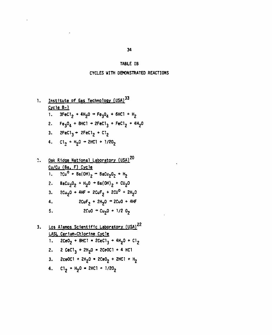
TABLE IB
CYCLES UITH DEMONSTRATED REACTIONS
1. Instituteof Gas Technolo~y (USA)33
Cycle B-1
1. 3FeC12 +4H20+Fe304 +
2. Fe304 + 8HC1 -2FeC13 +
3. 2FeC13+ 2FeC12 + C12
6HC1 + H2
FeC12 +4H20
4. C12 +H20 -2HC1 + 1/202
5-. Oak Ridge National Laboratory (USA)20
Cu/Cu (Ba, F) Cycle
1. 2Cu0 + Ba(OH)2 * BaCu202 + H2
2. BaCu202 + H20 +Ba(OH)2 + CU20
3. 2CU20+4HF+ 2CUF2 + 2CU” +2H20
4. 2CUF2+ 2H20 ~2Cu0 +4HF
5. 2CU0 +CU20 + 1/2 o~
3. Los Alamos Scle~tlffc LaboratorY (USA)22
LASL Cerium-ChlorlneCycle
1. 2Ce02 +8HC1 = 2CeC13 +4H20+C12
2. 2 CeC13 +2H20 =2CeOCl +4 HC1
3. 2ceOCl +2H20 ■ 2Ce02 +2HC1 + H2
4. C12 + H20 ■ 2HC1 + 1/202
35
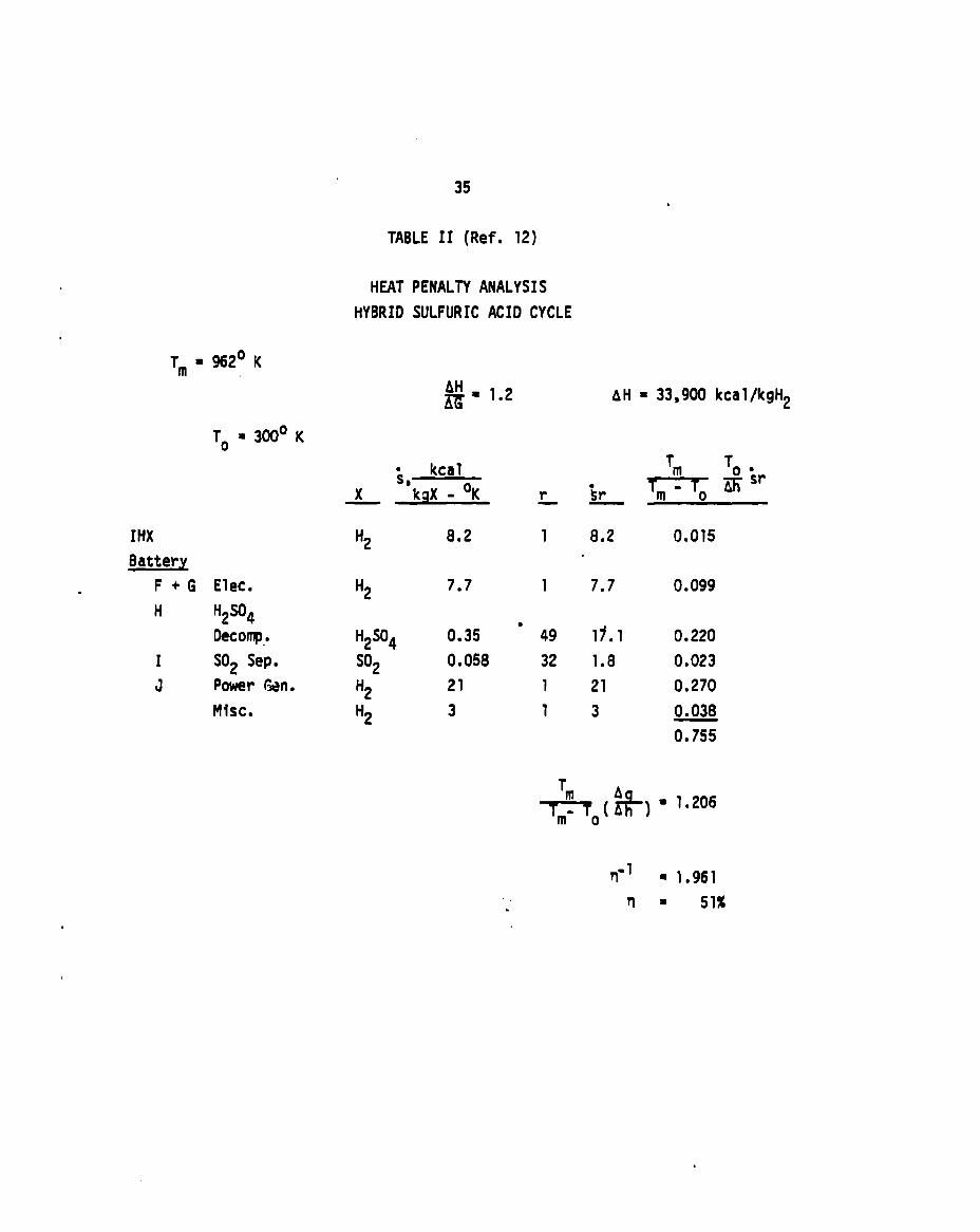
TABLE 11 (Ref. 12)
Tm = 962° K
To = 300° K
HEAT PENALTY ANALYSIS
HYBRID SULFURIC ACID CYCLE
#= 1.2 AH = 33,900 kcal/kgH9
kcali,—x kqX - oK
IHX ‘2 8.2
W!w!F +G Elec. ‘2 7.7.H H2S04
Decollp-. H2S04 0.35
I S02 Sep. S02 0.058
J Power WC‘2 21
Misc. ‘2 3
1
8.2
7.7
‘ 49 17.1
32 1.8
1 21
13
Tm To .
-Esr
0.015
0.099
0.220
0.023
0.270
0.038
=
+-TO(A*)=‘“206
rd = 1.961
n= 51%

36
TABLE III (Ref. 12)
HEAT PENALTY AND CAPITAL COST ANALYSIS
HYBRID SULFURIC ACIDCYCLE
1510 MU H2 0.48V* @ 2000 A/m2
Tm = 962°C*
m ‘2s04To = 300°C No 02 credit
NW DCC, 106$
A. Theoretical (ideal) Heat Requirement 1820
3. Heat Penalties
IHX 155
QQ!zJ!F+G Electrolyzer and ‘
Power Cond. 145
H H2S04 Deco~osition 323
I S02 Separation 35
J Power Generation 396
Miscellaneous 88
2962
q = 51%
83.4
200.6
- 167.6
23.6
57.1
G
*Overly-Optimisticassumed
50% H2S04, @ 2000 A/m2.
conditions, actual conditions are 0.6V at
37
TABLE IV
COSTS FOR THERMOCHEMICALAND ELECTROLYTICHYDROGEN - 10-15 YEAR FUTURE TECHNOLOGY (Ref. 35)
Mark 11 - V6 Mark 13 - V2 Electrolysis
Chw:cal Installations
Process Heat Exchangers
Interest Durina Construc-tion (%) -
ElectrolyzersOutput(14iTH)
ElectrolyticCellVoltage (V)
Required Electricity,DC (MWe)
Compressors Power (MWe)
Transformers and Rec-tifiers (lWe)
Required Electricity,AC (lWe)
Unit. Green Fix. Ann. Unit. Greencost Field Cost Char cost FieId($/kW) (MS) (%) (M$) wo!Q-
13.0
354.4 118.8
0.62
14ti.3
5.5
152.8 77.1
158.4
10.5
24.7
5.6
42.1
0.2
11.1
’25 4.6
25 6.1
11 0.6 13.0
.15 .6.3 354.4 118.8
0.80●
191.3
15 0.0 4.8
15 1.6 ?97.2 77.1
202.1
23.1
23.3
6.0
42.1
0.2
14.4
Fix.costM_
25
25
11
15
15
15
Ann. Unit. Green Fix. Ann.Cha- , Ccst Field Cost CharI!!Q M!!.ll!!YLf2_J!!!Q5.7
5.8
0.6
6.3 354.4 118.8 42.1 15 6.3
1.64
400.0
0.0
2.1 412.3 77.1 31.7 15 4.7 .
412.3

38
Recovered Electricity(MWe)
InterestDurin Con-struction (%?
Hydrogen Plant In-vestment
H2 Capacity(M3/H)*103
Capacity Factor (%)
Annual Produ tion,(GJ/yr)*10~
Overall Thermal Ef-ficiency (%)
Nuclear Heat Cost ($/GJ)
TABLE IV (continued)
COSTS FOR THERMOCHEMICALAND ELECTROLY~lCHYDROGEN - 10-15 YEAR FUTURE TECHNOLOGY (Ref. 35)
Mark 11 - V6 Mark 13 - V2 Electrolysis
Unit. Greencost Field
48.3 476.7
8.0
100.0
80.0
8.92
4?.4
1.7
14.2
23.0
6.1
119.8
Fix. Ann. Unit.Cost Char costE!._o!Q IY!!M.
15 3.4 48.5 476.7
11 0.6 8.0
23.6
100.0
80.0
8.92
37.2
?.7
24.9 13.8
GreenField(M$)
23.1
6.3
126.3
Fix. Ann. Unit. Green Fix. Ann.Cost Char cost Field Cost Charml!!!). @!!!!l J!!w_ll)_Q!!l
15 3.4
11 0.7 8.0 5.9 11 0.6
25.0 73.9 11.7
100.0
80.0
8.92
32.7
24.1

39
TABLE IV (continued)
COSTS FOR THERMOCHEMICALAND ELECTROLYTICHYDROGEN - 10-15 YEAR FUTURE TECHNOLOGY (Ref. 35)
Mark 11 - V6 Mark 13 - V2 _ Elect~O~ysfs
Lhit. Green Fix. Ann. Unit. Green Fix. Ann. Unit. Green Fix. Ann.cost Field Cost Char($/kW) (M$) (%) (M$)
cost Field Cost Char cost Field Cost Char($/kW) (M$) (%) (MS) l!lwl!!l!lmm
ElectricityCost(Mills/kWh) 20.0
Electric GeneratingEfficiency (%) 38.0
ElectricityRequired,(kWh/yr)*16 771.8
Non-energy Utilization(% of energy) 10.0
Total Annual Charges
Hydrogen ProductionCost ($C/M3) 9.70
Hydrogen ‘reductionCost ,j/GJ) 7.62
Hydrogen Productioncost ($/MBTU) 8.02
20.0 20.0
38.0 38.0
15.4 1076. 21.5 2889.
4.0 10.0 4.5 5.0
67.9 75.2
10.74 10.33
8.43 8.il
8.88 8.54
57.7
?.8
72.4
40
TABLE V
MATERIALS FACTOR (Ref. 25)
Carbon Steel
$tafnless Steel
Incoloy800
Graphite
1 Incoley 6F
2 Hastelloy C4
6,5 Titanium
8
10
11
12
TABLE VI ,
MAIN cHARACTERISTICSOF THE HYBRID SULFURIC ACID, MARK 11-V6 CYCLE (Ref. 30)
Plant Capacity
ElectrolyticCell Voltage
H2S04 Concentration in E?ectrolyt’~cGsll
ElectrolyticCell Temperature
ElectrolyticCell Pressure
/i2S04 Train Pressure
S03 decompositionTe~erature
S03 Conversion
HydroSen Delivery ?ressure
100,000 Nm3H2/h
0.62 V
75 Wt%
363 K
30 bar
10 bar
1083 K
52%
- 30 bar
Electricity Generation Efflclency 38%
Overall Thermal Efflclency 41.4%

41
TABLE VII
EFFICIENCY ANO HYIX?OGENPRODUCTION COST - THERMOCHEMICAL CYCLES
- ELECTROLYSIS -
EfficiencyCycle (%) &&U Done By
1, Hybrid Sulfuric Acid
54.1 5.56 !destinghouse
45.18 4.90 Westinghouse
47,0 7.80 Westinghouse
44.0 7.40 Funk-Lunms
41.3 8.85 Euratom
51 (0.48 v) 8.20 Funk-DOE Panel
40 (0.8 V) 10.00 Funk-DOE Panel
2, Hybrid Sulfuric Acid-Hydrogen Bromide (Ispra Mark 13)
36.9 9.70 Euratom
3. Zinc-Selenium
42.0 13050 LLL
4, Sulfurlc Acld-Hydroqen Iodide (6.A Ispra Mark 16)45+ M General Atomic
31 NA SCK/CEN, Belglum
41.4 NA Funk-Lunsnus
36.2 NA Funk-Lunsnus
5. Hybrid Bismuth Sulfate
41 NA IASL
6. Hybrid Copper Sulfate
37.1 NA IGT7. Sulfuric Acid (Water) Electrolysis
41 7.00 Westinghouse
8. Water Electrolysis (Advanced~
32.7 8.54 Euratom
Reference
8
8
32
12
25
26
26
25
,,27
13
14
12
12
24,25
18
32
31
Point,Fiq. El
A
B
I
c
o
E
F
G
H
J
K

FIGURE CAPTIONS
Fig. 1.
Fig. 2.
Fig. 3.
Fig. 40
Fig. 5.
Fig. 6,
Fig. 7,
Fig.8.
Fig.9.
Fig, 10,
Hydrogen from
42
a thermal energy source.
Hybrid sulfuric acid cycle, schematic diagram.
Sulfuric acid-hydrogen iodide cycle, schematic diagram.
Hybrid sulfuric acid-hydrogenbromide cycle, schematic diagram.
Hybrid bismuth sulfate cycle, LASL, schematic diagram.
Magnesium-iodinecycle, NCLI, Japan, schematic diagram.
Production cost, capital cost, and efficiency; hybrid sulfuric acid cycle.
Hybrid sulfuric acid c,ycle,Ispra Mark 11-V6 flowsheet (Ref. 30).
Parametric analysis of hydrogen production cost and efficelectrochemical cell voltage (Ref, 30).
Hydrogen production cost vs. efficiency for thermochemical’
●
ency vs.
cycles.

-43-
HYDROGEN FRC?ivlA RENEWABLE SOURCE
PRIMARY HEAT SOURCEs HIGH-TEMPERATURE
THERMOCHEMICAL● RANKINE CYCLE● BRAYTON CYCLE
- 60%
wASTEHEAT 02 (g)
H20(f2)
Fig. I. Hydrogen from a thermal ener~~ source.

-44-
HYBRID SULFUR ICACID THERMOCHEMICAL HYDROGEN CYCLE
D.C, ELECTRICAL THERMALENERGY Hz[g) ENERGY
HYDROGEN GENERATION(ELECTROLYZER)
SULFURIC ACID
2H20 + S02 ~ H2 + H2S04VAPORIZATION
HzO(!) H2S04●
● A
H20 H2S04
I Sc+
1 ,
SULCURIC ACII)SULFUR OIOXIDE/
OXYGEN SEPARATION~. DECOMPOSITION
02(9) H20, S02, 02 H2S04 + H20 + S02 + 1/202<
1 THERMALENERGY
Fig. 2. Hybrtd sulfuric acid cycle, schemattc dfagram.
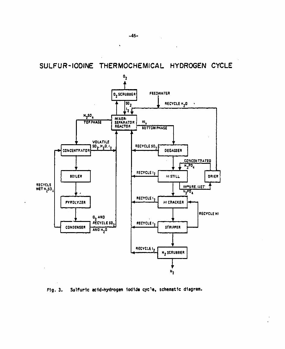
-45-
.
SULFUR-IODINE THERMOCHEMICAL HYDROGEN CYCLE
‘2
7% t
02 SCRUBBER FEEOWATER
;2 RECYCLEH20 *
.I t’+
‘2s04 f41XE&TOPPHASE W?ITA;O R Ht.
BOTTOMPHASE- -, I
RECYCLEwET HZSO
. 2EOILER
.
PYROLYZER
J-102ANO
~—.RECYCLESO.
=&l
. a
HI C8ACKER
I
RECYCLE124
Fig. 3. Sulfuric ecld-hydrogen Iodide cycle, schematic diagram.
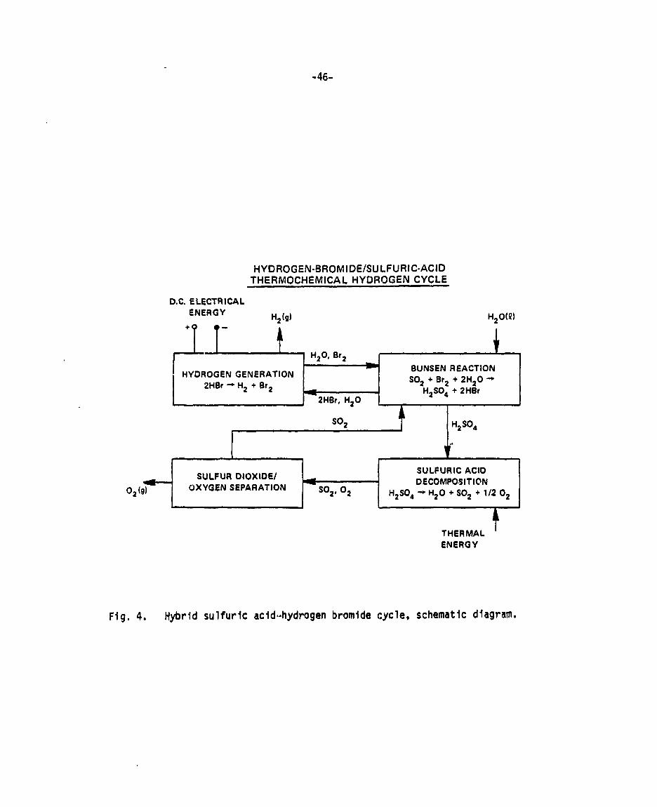
-46-
HYDROGEN-BROMIDE/SU LFURIC-ACIDTHERMOCHEMICAL HYORC)GEN CYCLE
D.C. ELECTRICALENERGY H2(g) H20(Q)
/u—
+
H20, Br2
HYDROGEN GENERATIONBUNSEN REACTIONS02 +Br2 +2H20~
2HBr~H2 +Br2 H2S04 + 2HBr2HBr, H20
S02
,.#‘
1 1
SULFUR DIOXIDE/SULFURIC ACID
OXYGEN SEPARATIONd DECOMPOSITION
02 (9) S02, 02 H2S04 + H20 + S02 + 1/2 02
THERMALI
ENERGY
Fig. 4. Hybrid sulfurlc acid-hydrogen bromide cycle, schematic diagram.
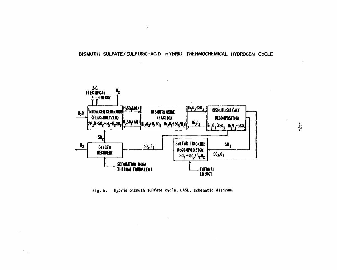
:
BISMUTH - SULFATE/ WURIC-ACIII HY13ftlD THERMOCHEMICAL HYOR06EhJ CYCl_E
D.C.
“n llYOlwxacEElural‘4Ao~ I!!WUIONDE “a~o’-m’+ BISNUTllSUIFAIE +-i-
(E1EWMMY2ER) REACTION MCOMPOSIUOHfi#$
Bi203-3s038iio343so$Di#3+$5’4 ~$’~qH*4
*I
L_ SEPAMJKM U(NK.lllERHAIEOUIMLEUT -“AL
EMEUGV
Fig. 5. Hybrid bismuth sulfate cycle, LASL, schematic diagram.
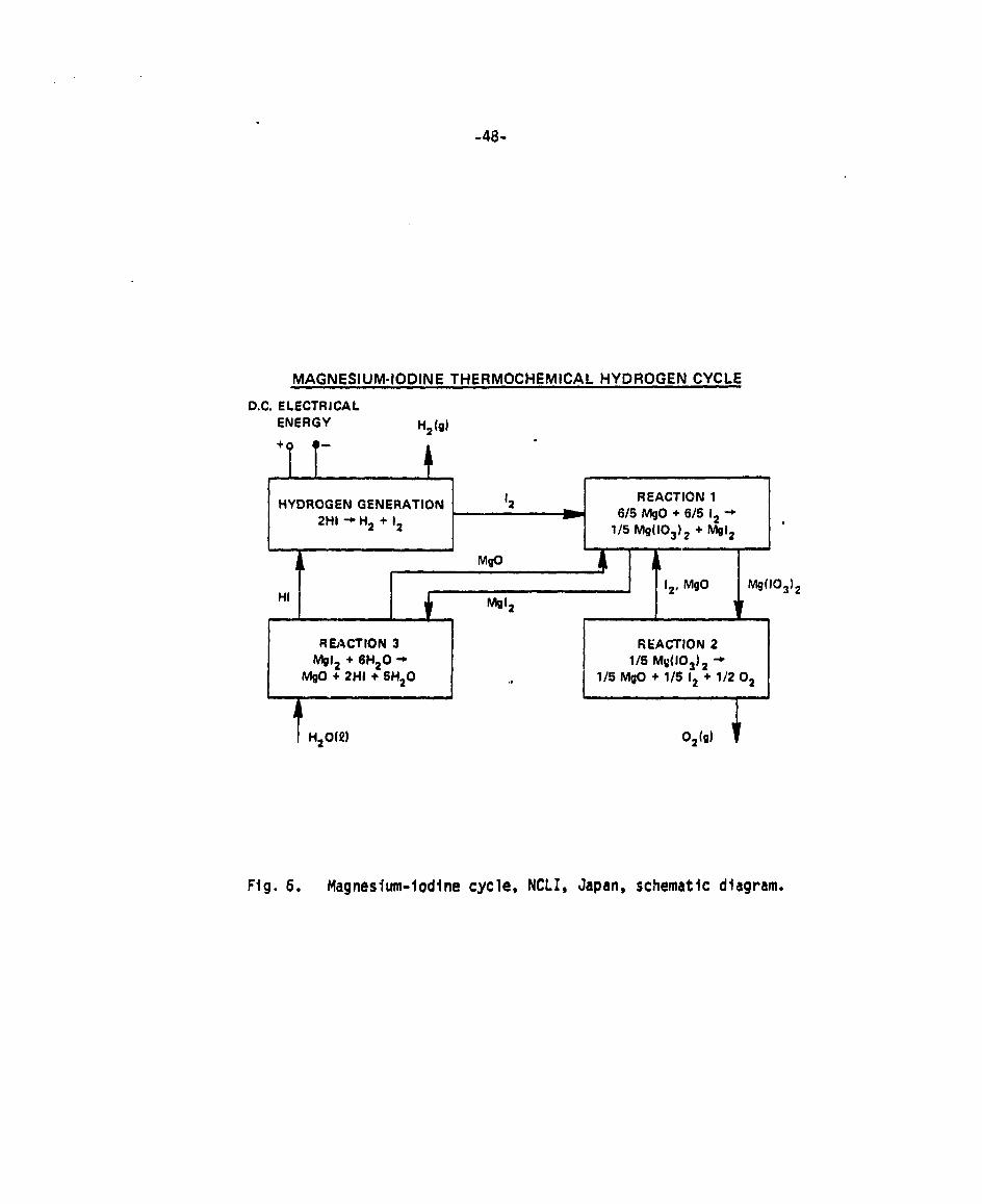
-48-
D.C.
MAGNESIUM-IODINE THERMOCHEMICAL HYDROGEN CYCLE
ELECTRICALENERGY Hz(g)
.
HYDROGEN GENERATION ‘2 REACTION 1
2HI+H2 +126/5 MgO + 61512 *
l/5 Mg(103)2 +Mg12 ‘
, , m
REACTION 3Mg12 + 6H20 +
MgO + 2HI + 5H20
i
TH20(Q)
,
REACTION 21/5 MQ(103)2 +
1/5 MgO + 1/5 12 + 1/2 02
1
02(g) i
Fig. 6. Magnesium-Iodine cycle, NCLI, Japan, schematic diagram.

A. ELECTRICAL POWER GENERATION ------ THERMOCHEMICAL HYBRID8. POWER CONDITIONING SULFURIC -ACIO CYCLE
C. ELECTROLYSIS —-—.–CONVENTIONAL ELECTROLYSISKEY OIRECT CAf? COST FOR CHEM. PLANT
—
—
p DIRECT CAPITAL COST>-
PRIMARY HEAT SOURCE
90 G07060 50 40 30 25
EFFICIENCY ,q (’%)
Fig. 7. Production cost, capital cost, and efficiency; hybrid sulfuric acid cycle.
1
sI

-50-
H20
O* +
sotABSORBERS
J30*O*
.
HCS04+ H20~’
VAPORIZER -DECOMPOSER
MARK 11 FLOWSHEET HYBRID SULFURIC ACID CYCLE
Fig. 8, Hybrtd sulfurlc acid cycle, Ispra Mark 11-V6 flowsheet (Ref. 30).

.
-51-
12
10
8
6
4
2
0
Fig. 9.
EURATOM HYBRID SULFURICACID CYCLE ( EURATOM MK I I-V6)
.
.
.
.
%4
42
-40
-38
- -36
134
32
0.4 0.6
CELL VOLTAGE
Parametric analysis of hydrogen productionelectrochemical cell voltage (Ref. 30).
9.8
cost and efficiency vs.
IAIAu

-52-
n
20
18
16
14
12
10
8
6
4
2
EFFICIENCY FORTHERMOCHEMICAL
\
-0.621) +37.O
●H
\I
HYDROGEN PRODUCTION
-0.357 + 23.0.
*
●G
●K
@d
.●A
“B.
.
1 I I I I
o 10 20 30 40 50 60 70
q , EFFICIENCY, (0/’)
Fig. 10. Hydrogm production cost vs. efficiency for thermochemical cycles.

53
REFERENCES
1.
2.
3.
4.
5.
6.
7.
8.
9.
10.
11.
12.
13.
14.
A. Konopka and J. Wurm, “Transmissionof Gaseous Hydrogen,” Proc. of the9th IECEC, 405-412 (1974).
R. E. Chao and K. E. Cox, in Hydroqen Energy, Vol. A (Plenum Press, NewYork, 19;5) pp. 317-330.
J. Vinderryn, F. Salzano, and M. G. Bowman, “InternationalCooperation onthe Development of Hydrogen Technologies,” Int. J. of Hydrogen Energy,1(4), 357 (1977).
G. Donat, B. Esteve, and J. P. Roncato, “ThermochemicalProduction ofHydrogen, Myth or Reality?” Per. Energie , 1-17 (April 1977).
J. E. Funk and R. M. Reinstrom, “Energy Requirements in the Production ofHydrogen from Water,” I&ECProc. Design and Develop. 5(3) (July 1966).
M. G. Bowman, “FundamentalAsp?cts of Systems for the ThermochemicalProduction of Hydrogen from Water,” 1st National Topical Me:ting onNuclear Process Heat Applications (October 1-3, 1974).
E. I. Onstott and M. G. Bowman, “Hydrogen Production by Low-VoltageElectrolysis in Combined Thermochemical and ElectrochemicalCycles,”Presented at 14fithMeeting of the ElectrochemicalSot. (October 13-17,1974).
G. H. Farbman, “Hydrogen Generation Process - Final Report,” WestinghouseElectric Corporation report FE-2262-15 (June 1977).
A. J. Appleby and B. Pichoii,“ElectrochemicalAspects of theH2S04-S02 Thermochemical Cycle for Hydrogen Production,” Proc. 2ndWorld Hydrogen Energy Conf. ~, 687-707 (August 1978).
B. D. Struck, “The Anodic Oxidation of Sulfur Dioxide in the Frame of theSulfuric Acid Cycle,” Proc. 2WHEC~ (August 1978).
G. H. Farbman, “The Conceptual Design of an Integrated Nuclear-HydrogenProduction Plant using the Sulfur Cycle Water Decomposition System,”Westinghouse Research Laboratories report NASA CR 13497S (April 1976).
J. E. Funk, “A TechnoeconomicAnalysis of Large Scale ThermochemicalProduction of-Hydrogen,” Electric Power Research Institute report EPRIEM-287 (December 1976).
J, D. deGraaf, et al., “Engineering and Bench-Scale Studies on the GeneralAtomic Sulf’’:--IodineThermochemical Water-Splitting Cycle,” Proc. 2WHEC~,545-568 (August 1978).
W. R. A. Goosens, M. Klein, and L. H. Baetsle, “Engineering Impact on theValidity of the Mark-16 ThermochemicalCvcle.” Proc. 2wHEC 2 (Auaust 1978).

54
15.
16.
17.
18.
19*
20.
21,
22 ●
23.
24,
25,
26,
27.
28.
D. van Velzen, et al, “Development,Design, and Operation of a ContinuousLaboratory Scale Plant for Hydrogen Production by the Mark 13 Cycle,” Proc.2WHEC~, 649-666 (August 1978).
G. Schutz and P. Fiebelmann, “Electrolysisof Hydrobromic Acid,” Proc.2WHEC~, 709-730 (August 1978).
A. Broggi, et al, “AMethod for the Techno-EconomicEvaluation of ChemicalProcesses: Improvementsto the OPTIMO Code,” Proc. 2WHEC4 (August 1978).
J. R. Dafler, S. E. Fob, and J. D. Schreiber, “Assessment of ThermochemicalHydrogen Production,” Institute of Gas Technology Interim Progress reportEC-77-C-02-4434for USDOE (May 1978),
E. H. Appelman, F. Schreiner, and B. M. Abraham, “ExperimentalVerificationof the Mercury-Iodine ThermochemicalCycle for the Production of Hydrogenfrom Water, ANL-4 ,“ Proc. 2nd World Hydroge,{Energy Conf. 2WHEC~, 851-907(August 1978).
C. E. Bamberger and 0. M. Richardson, “Recent Research on ThermochemicalHydrogen Production at the Oak Ridge National Laboratory,” Proc. 2WHEC~,763-790 (August 1978).
O. H. Krikorian, “The ZnSe ThermochemicalCycle for Hydrogen Production:Chemical and Process Design Studies,” Proc, 2WHEC~, 791-808 (August 197S;.
C. M. Hollabaugh, E. I. Onstott, T. C. Wallace, and M. G. Bowman, “A Studyof the Cerium-ChlorineSystem for Thermochemical Production of Hydrogen,”Proc. 2WHEC~, 809-828 (August 1978),
Japan’s Sunshine Project, Summary of H dro en EnerInternationalTrade and Industry, T~k~, ~pane ‘Ministry 0’
K, E. COX, “ThermochemicalProcess for Hydrogen Production,” Los AlamosScientific Laboratory report LA-7Z34-PR (May 1978).
L, A. Booth, et al, “Productionof ElectrothermochemicalHydrogen Using aFusion Source of High-TemperatureProcess Heat,” Proc. 3rd ANS TopicalMeeting on the Tech. of Controlled Nuclear FUSiOP (May 1978).
W. Kondo, et al, “The Magnesium-IodineCycle for the ThermochemicalDecomposition of Water,” Proc. 2WHEC~, 909-922 (August 1978).
K. Fujii, et a?, “The Calcium-IodineCycle for the ThermochemicalDecomposition of Water,” Int. J. Hydrogen Energy~, 413-422 (?977),
J. E. Funk. W. L. Col,ger,W. L. Carty, and R, E, Barker, ‘VhermochernicalProduction of Hydrogen from Water,” Proc. Brit. Nut. Energy Sot. Int’1,Conf. on High Temperature Reactor and Proc. Applic, (November 1974),

55
29. A Broggi St al, “OPTIMO, A Method for Process Evaluation Applied to theThermochemicalDecompositionof Water,” Int. J. of Hydrogen Energy, ~, 2$(1977).
30. A. Broggi, et al, “A Method for the Techno-Economic Evaluation of ChemicalProcesses, Improvementsto the OPTIMO-Code,” Proc. 2WHEC~, 2205-2230(August 1978).
31. A. Broggi, private communication (August 1978).
32. G. H. Farbman, et al, “Hydrogen Production using Electrolysis versus aHybrid Cycle,” Electric Power Research Institute (EPRI) report EM-789 (June1978).
33. J. D. Schreiber, J. R. Dafler, and S. E. Fob, “Equilitorium Effects inHigh-PressureHydrogen Production from ThermochemicalWater-SplittingCycles,” Proc. 2WHEC 2, 66d-685 (August 1978).