critical crack size computation for an axle
TRANSCRIPT
BEASY 2010-C
Critical crack size computation for an
axle Presented by Sharon Mellings
CM BEASY

BEASY 2010-C
Overview
� Axle, Wheel and Gear Assembly
� Geometry defined in paper by
“An investigation on the influence of rotary bending and press fitting on stress intensity factors and fatigue crack growth in railway axles”
M.Madia, S. Beretta, U. Zerbst
Engineering Fracture Mechanics, 75 (2008), 1906-1920

BEASY 2010-C
Overview
� Model creation:� Using model created in ABAQUS 6.10
� Defect Scanner:� Identify critical crack sizes and locations.
� SIF Computation� Crack added to assembly using a crack library
� SIF values over load cycle investigated
� Automatic Crack Growth� Full growth using load cycle

BEASY 2010-C
Overview
� In this presentation the same assembly will be defined in ABAQUS.� This will be used to create a BEASY model which is then solved using interference contact
� The model is created using solid FE elements in ABAQUS (or a shell representation could have been used)
� The FE model is then used to create a boundary element mesh.

BEASY 2010-C
Model assembly defined in ABAQUS

BEASY 2010-C
Assembly: Axle

BEASY 2010-C
Assembly: Wheel & Gear

BEASY 2010-C
Contact Analysis
� The different parts of the model will be connected using interface conditions.
� Both conforming and non-conforming contact are available� Here conforming contact will be utilised� The press-fit or interference fit is simulated using a negative initial gap� Note: Use of non-zero friction coefficient and the define negative initial gap removes the need to stop the gear and wheel from spinning
� The basic contact areas are defined in the ABAQUS cae and the details defined in the BEASY-ABAQUS interface tool.

BEASY 2010-C
Area of contact between axle and wheel

BEASY 2010-C
Area of contact between axle and gear

BEASY 2010-C
Meshed part in ABAQUS (using solid elements)

BEASY 2010-C
Creation of BEASY Model
� The BEASY model is then created from this assembly using a BEASY-ABAQUS interface tool.
� This “skins” the ABAQUS model and the external element faces are used to create BEASY elements.
� The displacement/force loading is created using the loading define in the ABAQUS model
� Contact interfaces are defined using the ABAQUS contact groups defined.

BEASY 2010-C
Contact Groups

BEASY 2010-C
Solved BEASY Model
� The BEASY model is then solved during which the contact solution will be run.
� The initial model has a single load case with the applied load, associated restraint and press-fit.

BEASY 2010-C
Exaggerated deformation of the axle

BEASY 2010-C
Defect Scanner
� The BEASY Defect Scanner is a tool that computes critical crack sizes in an assembly.
� Each point is investigated:� The maximum principal stress is computed
� A crack is defined oriented by the maximum principal stress direction
� The critical crack size is computed using reference solutions (appropriate to crack location and size)

BEASY 2010-C
Defect Scanner
� A critical crack is defined as one reaching either a threshold or critical SIF value� With threshold SIF we are looking at the smallest crack that will grow at each point
� With critical SIF we are looking for the smallest crack that will fail at each point.
� The smallest critical crack sizes is reported� Cracks are assumed to be circular
� A map of critical crack sizes (in ABAQUS result format) is produced.

BEASY 2010-C
Result output
� The result of using the defect scanner is a map of smallest critical crack sizes.
� Plotting small numbers in contour plots
� therefore a “Banded” output has been created.
� The smallest critical crack sizes are placed in a high band and the larges in a low band
� These can be customized as required.

BEASY 2010-C
Critical crack size (bands) for assembly

BEASY 2010-C
Plot of maximum principal stress values

BEASY 2010-C
Contact properties

BEASY 2010-C
How does the interference distance affect the critical
� Using a selected threshold SIF the computed critical crack sizes in the axle were computed using different interference distances.
Interference Distance
Critical Crack Size
0.12mm 0.0085mm
0.14mm 0.0054mm
0.16mm 0.0044mm

BEASY 2010-C
Varying initial interference distances
Red is smallest critical crack sizes < 0.005mm
Gap =0.12mm Gap =0.14mm
Gap =0.16mm

BEASY 2010-C
Detailed analysis of the critical crack
Initiating & growing a crack at the identified critical position

BEASY 2010-C
Crack Analysis
� A crack will now be added at one of the critical crack locations.
� This is chosen from a library of pre-defined crack shapes
� The loading will be changed, initially to be a series of 8 loads and associated restraints at different positions around the axle and wheel.
� In this analysis the load cases are solved independently
� Analysis could be performed using a load sequence to give transition from on load to the next

BEASY 2010-C
Adding the crack to the assembly model

BEASY 2010-C
Axle, wheel assembly

BEASY 2010-C
Boundary elements analysis
� In BEASY boundary elements is used to model the crack in the structure.
� This allows for just the crack faces to be defined� It is not necessary to remesh the entire domain
� Complex meshing and element grading around the crack is avoided.
� A wizard tool automatically meshes the part at each stage of the analysis.

BEASY 2010-C
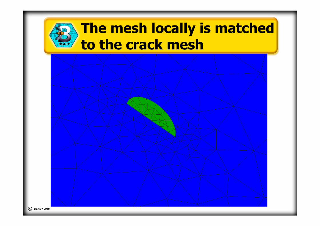
Mesh after crack is added
The mesh is just modified around the crack itself
BEASY 2010-C
The mesh locally is matched to the crack mesh

BEASY 2010-C
Initial SIF values along the crack front
30
40
50
60
70
80
90
100
110
0.0 0.1 0.2 0.3 0.4 0.5 0.6 0.7 0.8 0.9 1.0
Local position along crack front
SIF
K1 JINTPOS LC1
K1 JINTPOS LC2
K1 JINTPOS LC3
K1 JINTPOS LC4
K1 JINTPOS LC5
K1 JINTPOS LC6
K1 JINTPOS LC7
K1 JINTPOS LC8

BEASY 2010-C
Variation of SIF during the load cycle
30
40
50
60
70
80
90
100
110
120
1 2 3 4 5 6 7 8
Position:0
Position:1
Position:0.5
Load step number
SIF

BEASY 2010-C
Crack Growth
� The crack is now going to be grown
� In this analysis the two extreme load cases are being used for the load cycling
� Here the load cycle is relatively simple
� For a small crack, the same load case gives the maximum & minimum values for the entire front
� All load cases CAN be used to define the load cycle if required

BEASY 2010-C
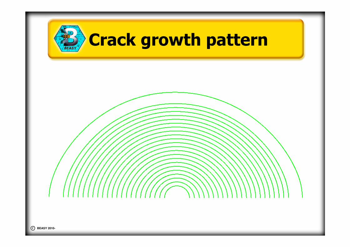
Growth of the crack
BEASY 2010-C
Crack growth pattern

BEASY 2010-C
Summary
� This presentation has shown:
� Creation of a BEM model using the ABAQUS cae
� Computation of critical crack size in a conforming contact model
� SIF analysis of a small crack at the critical crack location
� Growth of a small crack under a cyclic loading.