creo™ 2.0 m040 parametric and simulate configuration options · pdf filecreo® 2.0:...
TRANSCRIPT

Creo® 2.0: Parametric and Simulate
Configuration Options
Datecode M040
PTC Inc.

Copyright © 2013 PTC Inc. and/or Its Subsidiary Companies. All Rights Reserved.
User and training guides and related documentation from PTC Inc. and its subsidiary companies (collectively "PTC") are subject to the
copyright laws of the United States and other countries and are provided under a license agreement that restricts copying, disclosure, and
use of such documentation. PTC hereby grants to the licensed software user the right to make copies in printed form of this documentation
if provided on software media, but only for internal/personal use and in accordance with the license agreement under which the applicable
software is licensed. Any copy made shall include the PTC copyright notice and any other proprietary notice provided by PTC. Training
materials may not be copied without the express written consent of PTC. This documentation may not be disclosed, transferred, modified, or
reduced to any form, including electronic media, or transmitted or made publicly available by any means without the prior written consent
of PTC and no authorization is granted to make copies for such purposes.
Information described herein is furnished for general information only, is subject to change without notice, and should not be construed as a
warranty or commitment by PTC. PTC assumes no responsibility or liability for any errors or inaccuracies that may appear in this
document.
The software described in this document is provided under written license agreement, contains valuable trade secrets and proprietary
information, and is protected by the copyright laws of the United States and other countries. It may not be copied or distributed in any form
or medium, disclosed to third parties, or used in any manner not provided for in the software licenses agreement except with written prior
approval from PTC.
UNAUTHORIZED USE OF SOFTWARE OR ITS DOCUMENTATION CAN RESULT IN CIVIL DAMAGES AND CRIMINAL
PROSECUTION. PTC regards software piracy as the crime it is, and we view offenders accordingly. We do not tolerate the piracy of PTC
software products, and we pursue (both civilly and criminally) those who do so using all legal means available, including public and private
surveillance resources. As part of these efforts, PTC uses data monitoring and scouring technologies to obtain and transmit data on users of
illegal copies of our software. This data collection is not performed on users of legally licensed software from PTC and its authorized
distributors. If you are using an illegal copy of our software and do not consent to the collection and transmission of such data (including to
the United States), cease using the illegal version, and contact PTC to obtain a legally licensed copy.
Important Copyright, Trademark, Patent, and Licensing Information: See the About Box, or copyright notice, of your PTC software.
UNITED STATES GOVERNMENT RESTRICTED RIGHTS LEGEND
This document and the software described herein are Commercial Computer Documentation and Software, pursuant to FAR 12.212(a)-(b)
(OCT’95) or DFARS 227.7202-1(a) and 227.7202-3(a) (JUN’95), and are provided to the US Government under a limited commercial license
only. For procurements predating the above clauses, use, duplication, or disclosure by the Government is subject to the restrictions set forth
in subparagraph (c)(1)(ii) of the Rights in Technical Data and Computer Software Clause at DFARS 252.227-7013 (OCT’88) or Commercial
Computer Software-Restricted Rights at FAR 52.227-19(c)(1)-(2) (JUN’87), as applicable. 01282013
PTC Inc., 140 Kendrick Street, Needham, MA 02494 USA
PTC Inc. iii Creo Parametric and Simulate Configuration Options
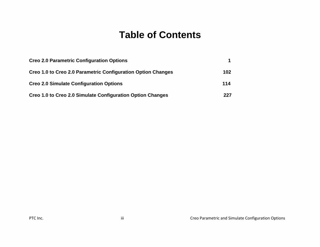
Table of Contents
Creo 2.0 Parametric Configuration Options 1
Creo 1.0 to Creo 2.0 Parametric Configuration Option Changes 102
Creo 2.0 Simulate Configuration Options 114
Creo 1.0 to Creo 2.0 Simulate Configuration Option Changes 227

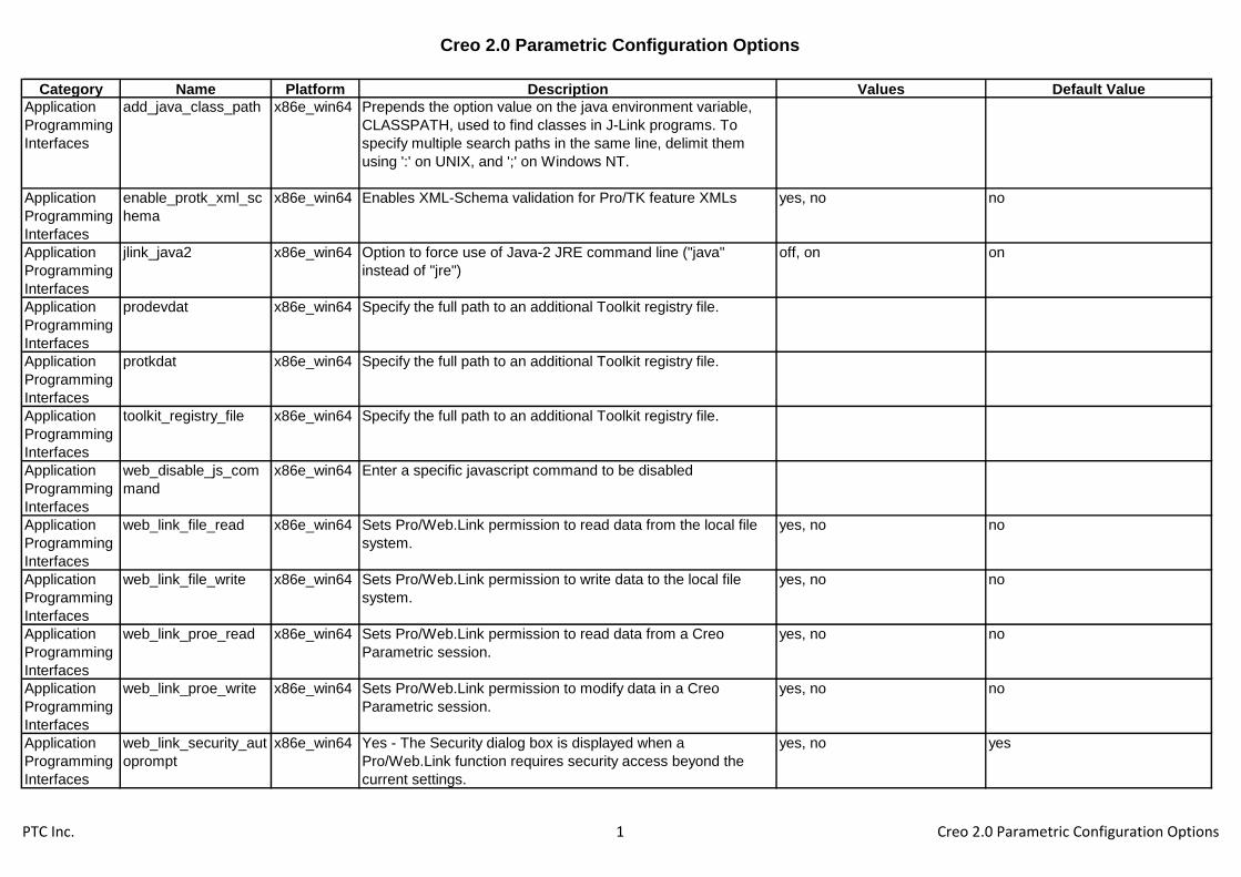
Creo 2.0 Parametric Configuration Options
Category Name Platform Description Values Default Value
Application
Programming
Interfaces
add_java_class_path x86e_win64 Prepends the option value on the java environment variable,
CLASSPATH, used to find classes in J-Link programs. To
specify multiple search paths in the same line, delimit them
using ':' on UNIX, and ';' on Windows NT.
Application
Programming
Interfaces
enable_protk_xml_sc
hema
x86e_win64 Enables XML-Schema validation for Pro/TK feature XMLs yes, no no
Application
Programming
Interfaces
jlink_java2 x86e_win64 Option to force use of Java-2 JRE command line ("java"
instead of "jre")
off, on on
Application
Programming
Interfaces
prodevdat x86e_win64 Specify the full path to an additional Toolkit registry file.
Application
Programming
Interfaces
protkdat x86e_win64 Specify the full path to an additional Toolkit registry file.
Application
Programming
Interfaces
toolkit_registry_file x86e_win64 Specify the full path to an additional Toolkit registry file.
Application
Programming
Interfaces
web_disable_js_com
mand
x86e_win64 Enter a specific javascript command to be disabled
Application
Programming
Interfaces
web_link_file_read x86e_win64 Sets Pro/Web.Link permission to read data from the local file
system.
yes, no no
Application
Programming
Interfaces
web_link_file_write x86e_win64 Sets Pro/Web.Link permission to write data to the local file
system.
yes, no no
Application
Programming
Interfaces
web_link_proe_read x86e_win64 Sets Pro/Web.Link permission to read data from a Creo
Parametric session.
yes, no no
Application
Programming
Interfaces
web_link_proe_write x86e_win64 Sets Pro/Web.Link permission to modify data in a Creo
Parametric session.
yes, no no
Application
Programming
Interfaces
web_link_security_aut
oprompt
x86e_win64 Yes - The Security dialog box is displayed when a
Pro/Web.Link function requires security access beyond the
current settings.
yes, no yes
PTC Inc. 1 Creo 2.0 Parametric Configuration Options

Creo 2.0 Parametric Configuration Options
Category Name Platform Description Values Default Value
Assembly add_offset_to_constra
int_comp
x86e_win64 Adds an offset dimensions to constraints that were created
without an offset during the dragging of a component.
yes, no no
Assembly advanced_intersectio
n
x86e_win64 Control the appearance of the intersection tool and scope of
available functionalities.
yes, no no
Assembly allow_package_childr
en
x86e_win64 Sets what type of children packaged components can have.
ALL - Features and components can be a children of packaged
component. FEAT - Only features can be children of packaged
components. NONE - Packaged components cannot have
children.
all, feat, none all
Assembly allow_redo_intersectio
ns
x86e_win64 Yes - Displays the ReIntersect command in the ASSY FEAT
menu.
yes, no no
Assembly allow_save_as_instan
ce
x86e_win64 Allows the option to save a copy of the active model as a family
table instance.
yes, no no
Assembly allow_save_failed_mo
del
x86e_win64 Yes - Failed models can be saved. No - Failed models cannot
be saved. Prompt - Let the user decide whether failed models
can be saved.
yes, no, prompt prompt
Assembly allow_update_part_si
mp_rep_data
x86e_win64 Allow updating part Simplified Rep data in session
automatically when switching from one Simp Rep to another.
Yes - Allow updating part simplified rep data. No - Do not
update part simplified rep data. Prompt - Prompt the user if the
current simplified rep should be updated.
yes, no, prompt yes
Assembly annot_elem_params_
with_units
x86e_win64 Some annotation element virtual parameters which were
previous passed unitless will not be passed as attributes with
units.
1
Assembly auto_assembly_with_
notebooks
x86e_win64 Yes - Enables automatic assembly. No - Disables automatic
assembly.
yes, no yes
Assembly auto_backup_new_pl
acemnt_refs
x86e_win64 Yes - Create Component Reference Backup, No - Do not
Create Component Reference Backup.
yes, no no
Assembly auto_constr_always_u
se_offset
x86e_win64 Control whether auto constraint should create offsets. Yes -
Auto constraint alw ays creates offsets. No - Auto constraint
snaps align or mate if surfaces are wi thin tolerance. Never -
Auto constraint never create offsets.
yes, no, never no
Assembly auto_evaluate_simpre
p_rules
x86e_win64 If the option is "yes" newly created rep would be updated each
time on retrieve/regeneration.
yes, no no
Assembly auto_place_max_num
ber
x86e_win64 Set the default value for the maximum number of matches
allowed.
5
PTC Inc. 2 Creo 2.0 Parametric Configuration Options

Creo 2.0 Parametric Configuration Options
Category Name Platform Description Values Default Value
Assembly auto_update_intersect
ed_models
x86e_win64 Control the appearance of the intersection tool and scope of
available functionalities.
yes, no yes
Assembly autoplace_single_co
mp
x86e_win64 Assembling components with an interface will automatically
place the component at the first position satisfying the interface
definitions.
yes, no yes
Assembly bump_revnum_on_ret
r_regen
x86e_win64 Determines whether or not revision number is increased for
generic models that regenerate and change during assembly
retrieval. Only applies if new_asm_regen_revnums is yes
(otherwise, there will be no revision number bumping).
yes, no yes
Assembly can_snap_to_missing
_ref
x86e_win64 Controls whether to enable snapping to missing references
while dragging components for placement. Yes - Snapping is
enabled while dragging. No - Snapping is disabled while
dragging.
yes, no yes
Assembly check_interface_criter
ia
x86e_win64 Check for interfaces when placing a component. yes, no no
Assembly check_interference_of
_matches
x86e_win64 Show only matches that do not interfere with other
components.
yes, no yes
Assembly check_same_assy_pa
rts
x86e_win64 Determines whether to permit different names for different part
occurrences, or not in mirror subassembly UI.
yes, no yes
Assembly chooser_size_filter_d
efault
x86e_win64 Sets the size filter default value as a percentage of the overall
assembly size
Assembly comp_angle_offset_e
ps
x86e_win64 Specifies the angle epsilon such that if the desired surfaces are
equal or greater than the epsilon (in degrees), than an angle
offset constraint will be created.
10
Assembly comp_assemble_start x86e_win64 Sets the initial assembly placement behavior when assembling
a new component. Default - Default initial position. Package -
Define initial position using the Move option.
Constraint_in_Window - Use secondary window.
Move_then_Place - Define initial position using the Move option
and then define placement constraints.
package, constrain_in_window,
default, move_then_place
Assembly comp_placement_ass
umptions
x86e_win64 Use placement assumptions when placing components. yes, no yes
Assembly comp_retr_angular_in
crement
x86e_win64 Sets the accuracy for the selection of external components
based on graphic computation.
1
Assembly comp_rollback_on_re
def
x86e_win64 No - Assembly is not rolled back when the user redefines a
component.
yes, no yes
PTC Inc. 3 Creo 2.0 Parametric Configuration Options

Creo 2.0 Parametric Configuration Options
Category Name Platform Description Values Default Value
Assembly copy_geom_update_p
re_2000i_dep
x86e_win64 Yes - Flags independent copy geom features in a pre-2000i
model as modified when retrieved into Creo Parametric. Save
the model immediately to update the model's copy geom
dependency information.
yes, no
Assembly copy_geometry_meth
od
x86e_win64 Sets the default copy geometry reference(s) type publish_geometry, references publish_geometry
Assembly create_temp_interfac
es
x86e_win64 Allow the automatic creation of interfaces based on previous
assembly instructions.
yes, no no
Assembly dim_inactive_compon
ents
x86e_win64 Display inactive assembly components with stippled
transparency and default color (grey). Default value is
shade_only.
never, always, shaded_only shaded_only
Assembly disp_regen_success_
msg
x86e_win64 Issue successfull regeneration messages for assembly
models.
yes, no no
Assembly enable_advance_colli
sion
x86e_win64 Enables advance collision settings usage. yes, no no
Assembly enable_assembly_acc
uracy
x86e_win64 No - Disables accuracy modification for assembly objects. yes, no yes
Assembly enable_implied_joints x86e_win64 Allow underconstrained components as mechanism
connections.
yes, no yes
Assembly erv_show_external_o
nly
x86e_win64 Yes - Global Reference Viewer will show objects with external
references only; No - all the objects will be visible
yes, no no
Assembly fail_ref_copy_when_
missing_orig
x86e_win64 Yes - When using a copied geom feature or a backed-up
external reference with the Design Manager, and the reference
is missing in the original, then the copied geom feature fails.
No - The feature freezes and does not update.
yes, no yes
Assembly fix_refs_to_intersectio
ns
x86e_win64 Sets remnant removal ability for the ReIntersect command in
the ASSY FEAT menu. Yes - You can remove remnants. No -
You cannot remove remnants.
yes, no no
Assembly force_upd_assem_m
p_in_simp_rep
x86e_win64 Update mass properties parameters even when some of the
components of the assembly are not in master rep.
yes, no, use_stored use_stored
Assembly freeze_failed_assy_co
mp
x86e_win64 No - Requires an action to fix the assembly or freeze the
component that fails retrieval. Yes - Freezes any component
failing retrieval at its last known assembly location. Missing refs
using offsets or internal datums do not cause components to
freeze.
yes, no no
PTC Inc. 4 Creo 2.0 Parametric Configuration Options
Creo 2.0 Parametric Configuration Options
Category Name Platform Description Values Default Value
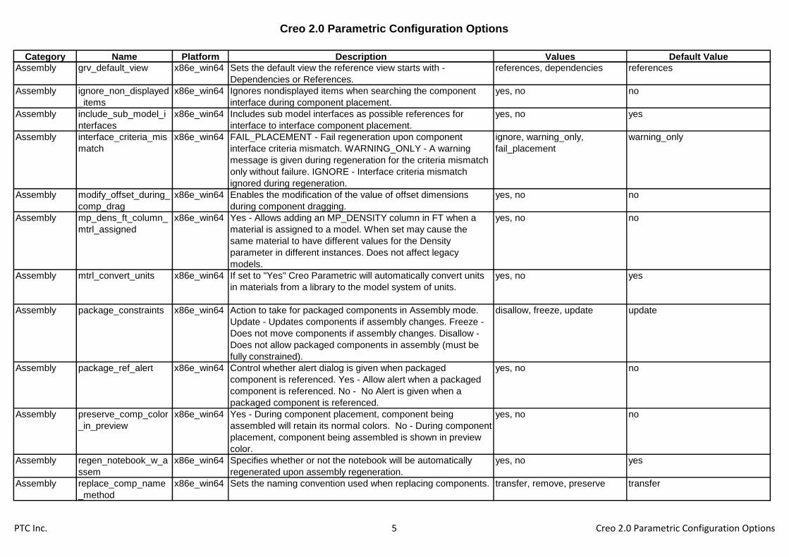
Assembly grv_default_view x86e_win64 Sets the default view the reference view starts with -
Dependencies or References.
references, dependencies references
Assembly ignore_non_displayed
_items
x86e_win64 Ignores nondisplayed items when searching the component
interface during component placement.
yes, no no
Assembly include_sub_model_i
nterfaces
x86e_win64 Includes sub model interfaces as possible references for
interface to interface component placement.
yes, no yes
Assembly interface_criteria_mis
match
x86e_win64 FAIL_PLACEMENT - Fail regeneration upon component
interface criteria mismatch. WARNING_ONLY - A warning
message is given during regeneration for the criteria mismatch
only without failure. IGNORE - Interface criteria mismatch
ignored during regeneration.
ignore, warning_only,
fail_placement
warning_only
Assembly modify_offset_during_
comp_drag
x86e_win64 Enables the modification of the value of offset dimensions
during component dragging.
yes, no no
Assembly mp_dens_ft_column_
mtrl_assigned
x86e_win64 Yes - Allows adding an MP_DENSITY column in FT when a
material is assigned to a model. When set may cause the
same material to have different values for the Density
parameter in different instances. Does not affect legacy
models.
yes, no no
Assembly mtrl_convert_units x86e_win64 If set to "Yes" Creo Parametric will automatically convert units
in materials from a library to the model system of units.
yes, no yes
Assembly package_constraints x86e_win64 Action to take for packaged components in Assembly mode.
Update - Updates components if assembly changes. Freeze -
Does not move components if assembly changes. Disallow -
Does not allow packaged components in assembly (must be
fully constrained).
disallow, freeze, update update
Assembly package_ref_alert x86e_win64 Control whether alert dialog is given when packaged
component is referenced. Yes - Allow alert when a packaged
component is referenced. No - No Alert is given when a
packaged component is referenced.
yes, no no
Assembly preserve_comp_color
_in_preview
x86e_win64 Yes - During component placement, component being
assembled will retain its normal colors. No - During component
placement, component being assembled is shown in preview
color.
yes, no no
Assembly regen_notebook_w_a
ssem
x86e_win64 Specifies whether or not the notebook will be automatically
regenerated upon assembly regeneration.
yes, no yes
Assembly replace_comp_name
_method
x86e_win64 Sets the naming convention used when replacing components. transfer, remove, preserve transfer
PTC Inc. 5 Creo 2.0 Parametric Configuration Options

Creo 2.0 Parametric Configuration Options
Category Name Platform Description Values Default Value
Assembly replace_history_rule_
order
x86e_win64 Set the default order of the history evaluation rule in the replace
operation. Disable - the evaluation rule will be disabled by
default. Number - set the order of the rule relative to other
evaluation rules.
1, 3, 2, disable, 4, 5 3
Assembly replace_interface_rule
_order
x86e_win64 Set the default order of the interface evaluation rule in the
replace operation. Disable - the evaluation rule will be disabled
by default. Number - set the order of the rule relative to other
evaluation rules.
1, 3, 2, disable, 4, 5 1
Assembly replace_sameid_rule_
order
x86e_win64 Set the default order of the same id evaluation rule in the
replace operation. Disable - the evaluation rule will be disabled
by default. Number - set the order of the rule relative to other
evaluation rules.
1, 3, 2, disable, 4, 5 5
Assembly replace_samename_r
ule_order
x86e_win64 Set the default order of the same name evaluation rule in the
replace operation. Disable - the evaluation rule will be disabled
by default. Number - set the order of the rule relative to other
evaluation rules.
1, 3, 2, disable, 4, 5 2
Assembly replace_sameparam_
rule_order
x86e_win64 Set the default order of the same parameters evaluation rule in
the replace operation. Disable - the evaluation rule will be
disabled by default. Number - set the order of the rule relative
to other evaluation rules.
1, 3, 2, disable, 4, 5 4
Assembly replace_unrelated_au
tomatic
x86e_win64 Availability of automatic reference pairing in unrelated replace.
No - Automatic reference pairing is not available. Yes -
Automatic reference pairing is available.
yes, no no
Assembly retrieve_instance_dep
endencies
x86e_win64 Determines whether to retrieve the dependencies of the
generic when an instance is retrieved.
instance_deps_only,
instance_and_generic_deps,
instance_req_generic
instance_req_generic
Assembly rv_current_object x86e_win64 Will control default option when setting a model or component
as the current object.
model, component, component
+ model
component + model
Assembly rv_search_scope x86e_win64 Sets the search scope for children when entering the reference
viewer. Session - Search all objects in session. Window -
Search objects in the active window only.
session, window session
Assembly search_area_for_com
p_interfaces
x86e_win64 Defines the search area for the component interface as a
percentage of the component size during component
placement.
100
Assembly search_not_retrieved
_models
x86e_win64 Expands search to include models that have not been retrieved
into session. If Yes, models will be brought into session
possibly causing performance issues.
yes, no yes
PTC Inc. 6 Creo 2.0 Parametric Configuration Options

Creo 2.0 Parametric Configuration Options
Category Name Platform Description Values Default Value
Assembly sel_insts_on_comp_r
etrieval
x86e_win64 Yes - If the components used in the assembly instances are
themselves generics, the systems asks if you want to choose
an instance as each component is retrieved. No - The generic
model of the component is retrieved automatically.
yes, no no
Assembly show_interference_in
_sections
x86e_win64 Yes - Interference will be shown automatically, No -
interference will not be shown automatically.
yes, no no
Assembly shrinkwrap_alert x86e_win64 Displays the Shrinkwrap alert the first time the quality level is
increased.
yes, no yes
Assembly simprep_default_mod
el_status
x86e_win64 Determines the default model status while defining a new
simplified rep.
master, geometry, exclude,
graphics, light graphics rep
exclude
Assembly simprep_ondemand_
selection
x86e_win64 Determines the rep to be retrieved when selecting a reference.
Automatic Retrieves the minimum rep required to perform the
operation.
automatic, master, disable automatic
Assembly simprep_ondemand_
settings
x86e_win64 Determines on-demand retrieval behavior in simplified
representation views. Prompt - Ask for confirmation before
retrieving on-demand. Never_prompt - Retrieve models on-
demand automatically with no confirmation. Disabled - on
demand is disabled.
prompt, disable, never_prompt never_prompt
Assembly skeleton_model_defa
ult_color
x86e_win64 Specifies the color Creo Parametric uses to display new
skeleton models. The three decimal values ranging from 0
through 100 specify (in order) the percentages of red, green,
and blue in the resulting color. For example, 0 0 49 specifies
medium blue.
0.000000 75.000000 100.000000
Assembly snap_to_constraints_
during_drag
x86e_win64 Enables the dynamic snapping to constraints during the
dragging of components.
yes, no yes
Assembly update_copy_geom_l
ocation
x86e_win64 Yes-Copy Geometry will try to update location of copied
geometry based on changes to component placements even if
some components are excluded or in graphics rep.
yes, no yes
Assembly update_rep_refs x86e_win64 "Yes" updates top assembly simplified reps for replacements
during regeneration and upon replacement.
yes, no yes
Assembly use_3d_thumbnail_in
_lwg_rep
x86e_win64 Control the usage of 3D thumbnails when retrieving in light
weight graphic representation
yes, no yes
Assembly use_active_model_in
_transform
x86e_win64 Transform analysis default behavior: use active model CSYS
and units or not.
yes, no no
Assembly
Process
curr_proc_comp_def_
color
x86e_win64 Specifies the default color used to display the current
component in a process assembly.
0.000000 0.000000 0.000000
PTC Inc. 7 Creo 2.0 Parametric Configuration Options
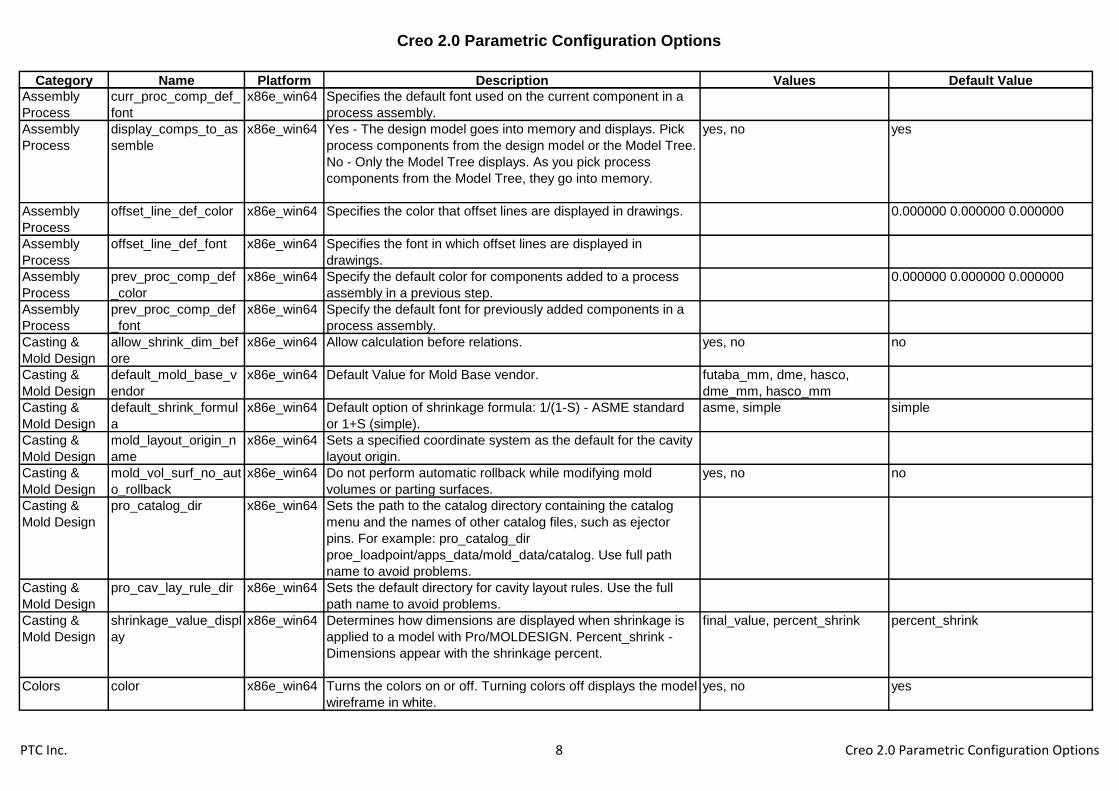
Creo 2.0 Parametric Configuration Options
Category Name Platform Description Values Default Value
Assembly
Process
curr_proc_comp_def_
font
x86e_win64 Specifies the default font used on the current component in a
process assembly.
Assembly
Process
display_comps_to_as
semble
x86e_win64 Yes - The design model goes into memory and displays. Pick
process components from the design model or the Model Tree.
No - Only the Model Tree displays. As you pick process
components from the Model Tree, they go into memory.
yes, no yes
Assembly
Process
offset_line_def_color x86e_win64 Specifies the color that offset lines are displayed in drawings. 0.000000 0.000000 0.000000
Assembly
Process
offset_line_def_font x86e_win64 Specifies the font in which offset lines are displayed in
drawings.
Assembly
Process
prev_proc_comp_def
_color
x86e_win64 Specify the default color for components added to a process
assembly in a previous step.
0.000000 0.000000 0.000000
Assembly
Process
prev_proc_comp_def
_font
x86e_win64 Specify the default font for previously added components in a
process assembly.
Casting &
Mold Design
allow_shrink_dim_bef
ore
x86e_win64 Allow calculation before relations. yes, no no
Casting &
Mold Design
default_mold_base_v
endor
x86e_win64 Default Value for Mold Base vendor. futaba_mm, dme, hasco,
dme_mm, hasco_mm
Casting &
Mold Design
default_shrink_formul
a
x86e_win64 Default option of shrinkage formula: 1/(1-S) - ASME standard
or 1+S (simple).
asme, simple simple
Casting &
Mold Design
mold_layout_origin_n
ame
x86e_win64 Sets a specified coordinate system as the default for the cavity
layout origin.
Casting &
Mold Design
mold_vol_surf_no_aut
o_rollback
x86e_win64 Do not perform automatic rollback while modifying mold
volumes or parting surfaces.
yes, no no
Casting &
Mold Design
pro_catalog_dir x86e_win64 Sets the path to the catalog directory containing the catalog
menu and the names of other catalog files, such as ejector
pins. For example: pro_catalog_dir
proe_loadpoint/apps_data/mold_data/catalog. Use full path
name to avoid problems.
Casting &
Mold Design
pro_cav_lay_rule_dir x86e_win64 Sets the default directory for cavity layout rules. Use the full
path name to avoid problems.
Casting &
Mold Design
shrinkage_value_displ
ay
x86e_win64 Determines how dimensions are displayed when shrinkage is
applied to a model with Pro/MOLDESIGN. Percent_shrink -
Dimensions appear with the shrinkage percent.
final_value, percent_shrink percent_shrink
Colors color x86e_win64 Turns the colors on or off. Turning colors off displays the model
wireframe in white.
yes, no yes
PTC Inc. 8 Creo 2.0 Parametric Configuration Options
Creo 2.0 Parametric Configuration Options
Category Name Platform Description Values Default Value
Colors color_ramp_size x86e_win64 Specifies the number of shades in a color ramp. Applicable to
multi-color, shaded model displays of simulation / analysis
results. System graphics must support 256 colors and color
maps that compress.
-1
Colors color_resolution x86e_win64 Specifies minimum allowable deviation between user-defined
colors. Colors having RGB values within tolerance of existing
colors cannot be created. Decreasing this setting allows more
colors that are very similar in RGB value to be defined.
0.1
Colors color_windows x86e_win64 All_windows - Wireframe colors display in the main window and
all auxiliary windows. One_window - Colors display only in the
main window. Auxiliary windows display wireframe in the
default color.
all_windows, one_window all_windows
Colors global_appearance_fil
e
x86e_win64 Material Global Appearance file path.
Colors mat_assign_appearan
ce
x86e_win64 Control whether default appearance in material definition is
automatically assigned to a part.
yes, no yes
Colors number_user_colors x86e_win64 Specifies the maximum number of different wireframe colors
that can display in the graphics area(s) at any given moment.
-1
Colors pro_colormap_path x86e_win64 Specifies the directory path for a color map (.map) file to be
loaded from disk. Use the full path name to avoid problems.
Colors suppress_appearance
_message
x86e_win64 Suppress the Lightworks appearance conversion notification
dialog.
yes, no no
Colors system_background_
color
x86e_win64 Defines default graphics area background color. The three
decimal values specify (in order) percentage of red, green and
blue in the resulting color. For example, 0 0 49 specifies a
medium blue. Change in session using View>Display
Settings>System Colors.
0.000000 0.000000 0.000000
Colors system_colors_file x86e_win64 Specifies the system color file. Use the full path name to avoid
problems.
Colors system_curves_color x86e_win64 Defines default curve color. The three decimal values specify
(in order) percentage of red, green and blue in the resulting
color. For example, 0 0 49 specifies a medium blue. Change in
session using View>Display Settings>System Colors.
0.000000 0.000000 0.000000
PTC Inc. 9 Creo 2.0 Parametric Configuration Options

Creo 2.0 Parametric Configuration Options
Category Name Platform Description Values Default Value
Colors system_dimmed_men
u_color
x86e_win64 Defines default secondary highlight color. The three decimal
values specify (in order) percentage of red, green and blue in
the resulting color. For example, 0 0 49 specifies a medium
blue. Change in session using View>Display Settings>System
Colors.
0.000000 0.000000 0.000000
Colors system_edge_high_c
olor
x86e_win64 Defines default edge highlight color. The three decimal values
specify (in order) percentage of red, green and blue in the
resulting color. For example, 0 0 49 specifies a medium blue.
Change in session using View>Display Settings>System
Colors.
0.000000 0.000000 0.000000
Colors system_geometry_col
or
x86e_win64 Defines default color of solid wireframe entities. The three
decimal values specify (in order) percentage of red, green and
blue in the resulting color. For example, 0 0 49 specifies a
medium blue. Change in session using View>Display
Settings>System Colors.
0.000000 0.000000 0.000000
Colors system_hidden_color x86e_win64 Defines default color of hidden, wireframe entities. The three
decimal values specify (in order) percentage of red, green and
blue in the resulting color. For example, 0 0 49 specifies a
medium blue. Change in session using View>Display
Settings>System Colors.
0.000000 0.000000 0.000000
Colors system_highlight_colo
r
x86e_win64 Defines default primary highlight color. The three decimal
values specify (in order) percentage of red, green and blue in
the resulting color. For example, 0 0 49 specifies a medium
blue. Change in session using View>Display Settings>System
Colors.
0.000000 0.000000 0.000000
Colors system_letter_color x86e_win64 Defines default color of datum tags. The three decimal values
specify (in order) percentage of red, green and blue in the
resulting color. For example, 0 0 49 specifies a medium blue.
Change in session using View>Display Settings>System
Colors.
0.000000 0.000000 0.000000
Colors system_section_color x86e_win64 Defines default section color. The three decimal values specify
(in order) percentage of red, green and blue in the resulting
color. For example, 0 0 49 specifies a medium blue. Change in
session using View>Display Settings>System Colors.
0.000000 0.000000 0.000000
PTC Inc. 10 Creo 2.0 Parametric Configuration Options

Creo 2.0 Parametric Configuration Options
Category Name Platform Description Values Default Value
Colors system_sheetmetal_c
olor
x86e_win64 Defines default color of Sheetmetal parts. The three decimal
values specify (in order) percentage of red, green and blue in
the resulting color. For example, 0 0 49 specifies a medium
blue. Change in session using View>Display Settings>System
Colors.
0.000000 0.000000 0.000000
Colors system_volume_color x86e_win64 Defines default color of Manufacturing volumes. The three
decimal values specify (in order) percentage of red, green and
blue in the resulting color. For example, 0 0 49 specifies a
medium blue. Change in session using View>Display
Settings>System Colors.
0.000000 0.000000 0.000000
Colors use_part_color_for_hi
dden_lines
x86e_win64 Determines how to color the hidden lines of parts that have
user defined colors. "YES" - Use the dimmed part color for
hidden lines. SYSTEM_HIDDEN_COLOR is ignored if it has
been specified.
yes, no no
Data
Exchange
acis_export_params x86e_win64 For ACIS interface allows to export object, feature and entity
level parameters.
yes, no no
Data
Exchange
acis_export_units x86e_win64 Allows selection of model units for ACIS export. micron, mm, default, in, ft, m,
cm
default
Data
Exchange
afx_enabled x86e_win64 Loads EFX application. yes, no no
Data
Exchange
atb_auto_check_on_a
ctivate
x86e_win64 Sets state of ATB 'Auto Check Status On Activate' toggle. off, on off
Data
Exchange
atb_auto_check_on_r
etrieve
x86e_win64 Sets state of ATB 'Auto Check Status On Retrieve' toggle. off, on on
Data
Exchange
atb_auto_check_on_u
pdate
x86e_win64 Sets state of ATB 'Auto Check Status On Update' toggle. off, on off
Data
Exchange
atb_ident_cadds_files x86e_win64 Allows to identify CADDS files in the file open browser. yes, no no
Data
Exchange
atb_prod_asm_upd_b
y_comp_ids
x86e_win64 Allows to update a Pro/DESKTOP assembly based on
assembly component ids, if set to YES. Otherwise, the update
will be based on component names.
yes, no yes
Data
Exchange
atb_show_log x86e_win64 Sets state of ATB 'Show Log' toggle. off, on on
Data
Exchange
auto_associate_dime
nsions
x86e_win64 If set to yes, Creo Parametric will attempt to take imported
dimensions that are not associative and link them to geometric
entities so that they act as associative.
yes, no no
PTC Inc. 11 Creo 2.0 Parametric Configuration Options

Creo 2.0 Parametric Configuration Options
Category Name Platform Description Values Default Value
Data
Exchange
board_bend_notes_df
lt_display
x86e_win64 Defines the default state of board bend note display. yes, no yes
Data
Exchange
board_bend_notes_di
rection_down
x86e_win64 Defines the down direction symbol for board bend notes. default
Data
Exchange
board_bend_notes_di
rection_up
x86e_win64 Defines the up direction symbol for board bend notes.
Data
Exchange
board_bend_notes_or
der
x86e_win64 Defines the fields order for board bend notes. &type&direction&angle
Data
Exchange
board_bend_notes_ty
pe_formed
x86e_win64 Defines the formed symbol for board bend notes. default
Data
Exchange
board_bend_notes_ty
pe_rolled
x86e_win64 Defines the rolled symbol for board bend notes. default
Data
Exchange
board_bend_table_dir
ectory
x86e_win64 Will be used to set the bend allowance table only. Sets the
default directory of the board bend allowance table files. If not
set, the system supplied bend tables are used. Use the full
name and path to avoid problems.
Data
Exchange
board_design_rules_d
irectory
x86e_win64 Will be used to set the design rules file folder only. Will be used
by the design rules manager. Sets the default directory of the
board design rules files. Use the full name and path to avoid
problems.
Data
Exchange
board_drive_bend_by
_parameters
x86e_win64 Board bend radius and bend angle values and bend dimension
location will be driven by feature-level relations to board
parameters.
yes, no no
Data
Exchange
board_drive_tools_by
_parameters
x86e_win64 Drives the board options and values by feature-level relations
to board parameters.
yes, no yes
Data
Exchange
board_flat_shape_ske
tches_dir
x86e_win64 Sets path to directory that contains the Flat shapes.
Data
Exchange
board_parameters_dir
ectory
x86e_win64 Specifies the directory to save/retrieve board parameters files.
Use full name and path to avoid problems.
Data
Exchange
cadds_import_layer x86e_win64 Allows import of CADDS5 layering. yes, no yes
Data
Exchange
catia_out_to_existing
_model
x86e_win64 Append - If the selected CATIA model already exists, the new
data is appended to the existing CATIA file. Overwrite - If the
selected CATIA model already exists, the newly exported file
overwrites the existing one.
append, overwrite append
Data
Exchange
cgm_use_pentable x86e_win64 No - Do not use a defined pen table for formatting of CGM
export.
yes, no no
PTC Inc. 12 Creo 2.0 Parametric Configuration Options

Creo 2.0 Parametric Configuration Options
Category Name Platform Description Values Default Value
Data
Exchange
cri_grafting_enable x86e_win64 Activates "Graft features" button under File menu. This allows
user to graft features created in CRI model to active model.
yes, no no
Data
Exchange
dazix_default_placem
ent_unit
x86e_win64 Specifies the units to be used for data imported in Dazix files. micron, mm, thou
Data
Exchange
dazix_export_mounth
ole
x86e_win64 Yes - Causes the MOUNTHOLE section of a Dazix file to be
processed as a mount hole. No - Causes the MOUNTHOLE
section to be processed as a cut.
yes, no no
Data
Exchange
dazix_z_translation x86e_win64 Yes - Passes the objects in the .edn files through z translation. yes, no yes
Data
Exchange
direct_vrml x86e_win64 Yes - Enables direct VRML conversion. yes, no no
Data
Exchange
dwg_export_format x86e_win64 Provides the ability to choose DWG file version when exporting
from Creo Parametric drawing.
14, 2000, 2004, 2007, 2010 2007
Data
Exchange
dxf_block_to_pro_sy
mbol
x86e_win64 Specifies whether or not DXF BLOCKS to be imported as Creo
Parametric symbols. Yes - Imports BLOCKS as symbol
definitions, No - Imports BLOCKS as separate entities.
yes, no no
Data
Exchange
dxf_export_format x86e_win64 Provides the ability to choose DXF file version when exporting
from Creo Parametric drawing.
12, 13, 14, 2000, 2004, 2007,
2010
2007
Data
Exchange
dxf_in_faceted_brep x86e_win64 Default, faceted boundary representation is allowed in import. yes, no yes
Data
Exchange
dxf_in_proxy_entity x86e_win64 Controls the input support for ACAD_PROXY_ENTITY. yes, no yes
Data
Exchange
dxf_out_comments x86e_win64 YES - comments (999 group codes) will be created in DXF file
exported from Creo Parametric. NO - DXF file will be created
without comment lines.
yes, no yes
Data
Exchange
dxf_out_drawing_scal
e
x86e_win64 Specify whether or not to export drawing scale to the DXF or
DWG file. Yes - Includes a scale factor DIMLFAC in the
exported DXF/DWG. No - Exports without using a scale for the
drawing. Set to Yes when exporting to read into AutoCAD.
yes, no no
Data
Exchange
dxf_out_scale_views x86e_win64 Specify whether or not to scale drawing views when exporting
to the DXF or DWG file. Yes - rescales the entire drawing in
such a way that the main view scale becomes 1:1. No -
exports without rescaling.
yes, no no
PTC Inc. 13 Creo 2.0 Parametric Configuration Options

Creo 2.0 Parametric Configuration Options
Category Name Platform Description Values Default Value
Data
Exchange
dxf_out_sep_dim_w_
breaks
x86e_win64 YES - Breaks dimensions with breaks on witness lines to
separate entities and preserves the original picture. No -
Exports such dimensions as DXF DIMENSION entities and
removes the breaks on witness lines.
yes, no no
Data
Exchange
dxfio_in_sjis x86e_win64 Determines if the SJIS is supported when importing/exporting
DXF files in Japanese
yes, no yes
Data
Exchange
ecad_area_default_im
port
x86e_win64 Defines how imported ECAD areas are treated. Cosm_area -
Treats imported ECAD areas as cosmetic area features.
3d_volume - Imports ECAD areas with Z-heights as a 3D
enclosed quilt.
3d_volume, cosm_area cosm_area
Data
Exchange
ecad_board_csys_def
_name
x86e_win64 Specifies the default coordinate system name added to an
ECAD board being imported. If you do not set this variable, the
system prompts you for a name.
Data
Exchange
ecad_comp_csys_def
_name
x86e_win64 Specifies the default coordinate system name added to an
ECAD component being imported. If you do not set this
variable, the system prompts you for a name.
Data
Exchange
ecad_comp_layer_ma
p
x86e_win64 Allow layer mapping for ECAD component's import into
Assembly.
yes, no yes
Data
Exchange
ecad_comp_naming_
convention
x86e_win64 ECAD_NAME / ECAD_ALT_NAME - Uses the components
package name or part number as the part name.
ECAD_NAME_ECAD_ALT_NAME - Concatenates the
component's package name and part number as the part
name.
ecad_name,
ecad_name_ecad_alt_name,
ecad_alt_name
ecad_name
Data
Exchange
ecad_comp_xsec_def
_name
x86e_win64 Will allow pre-setting default X-section to be used for
component outline output to *.eda format.
Data
Exchange
ecad_create_hint_add x86e_win64 Assists in creation of an ecad_hint.map file. Yes - Automatically
renames components, if necessary, each time library of
component outlines is imported to Creo Parametric. This does
not create an ecad_hint.map file. It controls if ecad_hint.add is
created.
yes, no yes
Data
Exchange
ecad_default_comp_h
eight
x86e_win64 Sets default value and units for an ECAD component being
imported. Units can be: inch, mil (1E-3 inches), thou (1E-6
inches), cm, mm, micron (1E-6 meters), dsu (1E-8 meters). If
not set, the system uses the current component's units.
-1.000000 ecad_unit_not_set
Data
Exchange
ecad_default_comp_p
lace_status
x86e_win64 Sets default component placement status for export
(parameter setting will override the default).
unplaced, fixed, placed, mcad,
ecad
placed
PTC Inc. 14 Creo 2.0 Parametric Configuration Options

Creo 2.0 Parametric Configuration Options
Category Name Platform Description Values Default Value
Data
Exchange
ecad_edmd_out_versi
on
x86e_win64 Set the EDMD output version. 2.0, 1.2 2
Data
Exchange
ecad_exp_both_two_
areas
x86e_win64 Supports the export of ECAD areas with different "Above
Board" and "Below Board" conditions. "yes" - Enables you to
export both sided keep-in/keep-out ECAD areas as two
individual areas (top and bottom).
yes, no no
Data
Exchange
ecad_export_cuts_as
_holes
x86e_win64 Exports Creo Parametric cuts as holes to ECAD systems. yes, no yes
Data
Exchange
ecad_export_holes_a
s_cuts
x86e_win64 Exports Creo Parametric holes as cuts to ECAD systems. yes, no no
Data
Exchange
ecad_import_holes_a
s_features
x86e_win64 Import sections specified as DRILLED_HOLE as through-all
holes. Boards created with Creo Parametric drilled holes export
with default value of NPTH for the ECAD_HOLE_TYPE
parameter. Create this feature parameter if a value of PTH is
needed (IDF 2.0/3.0).
yes, no yes
Data
Exchange
ecad_import_relative_
accuracy
x86e_win64 Defines the relative accuracy used in ECAD import. 0.0012
Data
Exchange
ecad_mapping_file x86e_win64 Specify the ecad_hint.map file that will be used for ECAD
operations.
Data
Exchange
ecad_missing_compo
nent_status
x86e_win64 Setup default status for missing components in "Investigate
Placement" Dialog.
keep_missing, delete_missing keep_missing
Data
Exchange
ecad_mtg_hole_impor
t
x86e_win64 Setup the default for the import of ECAD Holes type MTG (IDF
3.0 or IDX ONLY)
yes, no, as lightweight yes
Data
Exchange
ecad_other_outl_csys
_def_name
x86e_win64 Specifies the default coordinate system name for the
.OTHER_OUTLINE section of an IDF 2.0 ECAD component
being imported. If you do not set this variable, the system uses
ECAD DEFAULT as coordinate system name.
Data
Exchange
ecad_panel_csys_def
_name
x86e_win64 Specifies the default coordinate system name added to an
ECAD panel being imported. If you do not set this variable, the
system prompts you for a name.
Data
Exchange
ecad_pin_hole_import x86e_win64 Set up the default for the import of ECAD Holes from type PIN
(IDF 3.0 or IDX ONLY)
yes, no, as lightweight no
Data
Exchange
ecad_reject_strategy x86e_win64 Configures the way the changes are rejected. ui_based, as_original, as_base ui_based
Data
Exchange
ecad_set_intercomm_
compatible
x86e_win64 Yes - Set both EDA format version and output method to
support InterComm product, yes or no.
yes, no no
PTC Inc. 15 Creo 2.0 Parametric Configuration Options

Creo 2.0 Parametric Configuration Options
Category Name Platform Description Values Default Value
Data
Exchange
ecad_tool_hole_impor
t
x86e_win64 Setup the default for the import of ECAD Holes type TOOL
(IDF 3.0 or IDX ONLY)
yes, no, as lightweight yes
Data
Exchange
ecad_via_hole_import x86e_win64 Set up the default for the import of ECAD Holes from type VIA
(IDF 3.0 or IDX ONLY)
yes, no, as lightweight yes
Data
Exchange
ecadcollab_auto_rede
f_areas
x86e_win64 Automatically redefine ECAD Areas affected by collaboration
changes
yes, no yes
Data
Exchange
ecadcollab_auto_rede
f_comps
x86e_win64 Automatically redefine components affected by collaboration
changes
yes, no yes
Data
Exchange
ecadcollab_auto_rede
f_holes
x86e_win64 Automatically redefine holes affected by collaboration changes yes, no yes
Data
Exchange
ecadcollab_preview_l
evel
x86e_win64 ECAD Collaboration preview Level full, partial, light partial
Data
Exchange
ecadcollab_scan_des
_on_area_chg
x86e_win64 Check for affected objects resulting from ECAD Areas
collaboration changes
yes, no yes
Data
Exchange
ecadcollab_scan_des
_on_brd_chg
x86e_win64 Check for affected objects resulting from board collaboration
changes
yes, no yes
Data
Exchange
ecadcollab_scan_des
_on_comp_chg
x86e_win64 Check for affected objects resulting from components
collaboration changes
yes, no yes
Data
Exchange
ecadcollab_scan_des
_on_hole_chg
x86e_win64 Check for affected objects resulting from holes collaboration
changes
yes, no yes
Data
Exchange
ecadcollab_supp_faile
d_feats
x86e_win64 Suppress of failed features on Object changes yes, no yes
Data
Exchange
ecadcollab_suppress
_cuts
x86e_win64 Automatically suppress cut features in case of board
collaboration changes
yes, no yes
Data
Exchange
enable_acis_export_e
xtension
x86e_win64 Enable ACIS export extension. yes, no no
Data
Exchange
enable_cadra_export x86e_win64 Enables the CADRA command in the EXPORT menu. This
enables the creation of a CADRA specific IGES file.
yes, no no
Data
Exchange
explode_iges_dimensi
on_note
x86e_win64 Controls how dimensions are treated when importing an IGES
drawing file. Yes - Each IGES dimension explodes into an
independent note with the dimension text and a dimension with
an empty note. No - Dimensions are treated as before.
yes, no no
Data
Exchange
export_3d_force_defa
ult_naming
x86e_win64 Specify whether the Creo Parametric model names should be
used for STEP export. Yes - Use default naming. No - Add
suffixes to model file names.
yes, no no
Data
Exchange
export_to_shipit x86e_win64 Enable Ship-it interface export. yes, no no
PTC Inc. 16 Creo 2.0 Parametric Configuration Options
Creo 2.0 Parametric Configuration Options
Category Name Platform Description Values Default Value
Data
Exchange
extend_cvpath x86e_win64 Extends CVPATH search path for CADDS5 data exchanging.
Data
Exchange
fix_autocad_iges_text
_scale
x86e_win64 Fixes scaling problems with AutoCAD releases earlier than
Release 10. Yes - Repairs AutoCAD files appropriately.
yes, no no
Data
Exchange
fix_catia_iges_sym_n
ote
x86e_win64 Corrects a problem caused by multiple rotations of a note in a
CATIA IGES file. Yes - Rectifies any discrepancies.
yes, no no
Data
Exchange
fix_imported_set_view
_orient
x86e_win64 Sets viewing characteristics for imported CATIA SET files. Yes -
Files can have translated views. No - Files cannot have
translated views.
yes, no no
Data
Exchange
frt_enabled x86e_win64 Loads feature recognition application. yes, no no
Data
Exchange
iges_clip_view_ent x86e_win64 Determines whether IGES entities are clipped with regards to
IGES views. YES - Entities outside the view outline are clipped.
NO - No clipping.
yes, no yes
Data
Exchange
iges_clip_view_note x86e_win64 Determines how IGES notes are clipped with regards to IGES
views. No_clip - No clipping. Full_clip - Notes that are partially
outside the view outline are clipped. Partial_clip - Notes
completely outside the view outline are clipped.
no_clip, full_clip, partial_clip no_clip
Data
Exchange
iges_export_dwg_vie
ws
x86e_win64 Yes - Exports drawing view information. No - Does not export
drawing view information.
yes, no no
Data
Exchange
iges_in_dwg_color x86e_win64 Yes - Import RGB information to IGES files. The color definition
entities in the IGES file are imported to the drawings as user-
defined colors. No - The color-definition entities in the IGES
files are ignored when importing to the drawing.
yes, no no
Data
Exchange
iges_in_dwg_line_font x86e_win64 Controls the import of user-defined line fonts. Yes - Give
default names to user-defined line styles without names in
order ("IGES_1," "IGES_2" etc.). No - Imports the user-defined
line fonts as Solid line font.
yes, no no
Data
Exchange
iges_in_group_to_dw
g_layer
x86e_win64 Yes - Converts an IGES group to drawing layers. No - The
IGES group is not converted.
yes, no no
Data
Exchange
iges_note_disp x86e_win64 Determines what to do when IGES note entities do not point to
any views or the drawing entity. See the configuration option
iges_zero_view_disp.
as_geometry, all_views,
no_views, as_is
all_views
PTC Inc. 17 Creo 2.0 Parametric Configuration Options

Creo 2.0 Parametric Configuration Options
Category Name Platform Description Values Default Value
Data
Exchange
iges_out_all_srfs_as x86e_win64 Default - Outputs all surfaces as appropriate IGES surfaces.
114 - This option applies only to representations of surface
shape. Trimmed surface entities (type 144) are exported
regardless of setting. 128 - Outputs all surfaces as IGES B-
spline surfaces.
128, 114, default default
Data
Exchange
iges_out_assembly_d
efault_mode
x86e_win64 Set default for assembly export via IGES. Flat - Single level
model. One_level - Assy structure with pointers to components.
All_levels - Assy structure with all comps to IGES files.
All_parts - Assy to IGES files with geom info of comps and
assy feats.
flat, one_level, all_levels,
all_parts
flat
Data
Exchange
iges_out_catia_gdt_wi
dth
x86e_win64 Yes - Enables the desired width of a gtol symbol to be exported
to CATIA.
yes, no no
Data
Exchange
iges_out_catia_notes x86e_win64 Yes - Breaks a large note (greater than 70 strings) down into
smaller notes, each producing an IGES entity.
yes, no no
Data
Exchange
iges_out_dwg_color x86e_win64 Yes - Enables the export of RGB information to IGES files. The
user-defined colors in the drawing are exported to an IGES file
as color definition entities. No - Ignores the user-defined colors
in the drawing when exporting IGES file.
yes, no no
Data
Exchange
iges_out_dwg_line_fo
nt
x86e_win64 Controls the export of user-defined line font through IGES. No -
Exports all geometry as solid font.
yes, no no
Data
Exchange
iges_out_ent_as_bspl
ine
x86e_win64 True - Exports all geometry entities, other than lines or arcs, as
third-degree B-splines. False - Does not export entities as third-
degree B-splines.
true, false FALSE
Data
Exchange
iges_out_jamais_com
pliant
x86e_win64 Yes - Specifies IGES output with special JAMA-IS subset
specification, compliant with the version 1.02 of JAMA-IS
(Japan Automobile Manufacturers Association IGES Subset
Specification). No - Specifies normal IGES.
yes, no no
Data
Exchange
iges_out_mil_d_2800
0
x86e_win64 Yes - Specifies IGES output that uses the MIL-D-28000 entity
subset.
yes, no no
Data
Exchange
iges_out_spl_crvs_as
_126
x86e_win64 Converts all part geometry spline curves to IGES entity 126 (B-
spline) when creating an IGES file.
yes, no yes
Data
Exchange
iges_out_spl_srfs_as
_128
x86e_win64 Converts all part geometry spline surfaces to IGES entity 128
(B-spline) when creating an IGES file.
yes, no yes
Data
Exchange
iges_out_start_note x86e_win64 Yes - Exports the text specified by system_iges_header_file
and user_iges_header_file as a note on the drawing. To control
note placement, use the configuration file option
put_iges_drawing_entity.
yes, no no
PTC Inc. 18 Creo 2.0 Parametric Configuration Options

Creo 2.0 Parametric Configuration Options
Category Name Platform Description Values Default Value
Data
Exchange
iges_out_symbol_entit
y
x86e_win64 Exports a drawing symbol as an IGES general symbol entity,
IGES type number 228 (yes), or as its component entities:
notes and lines.
yes, no yes
Data
Exchange
iges_out_trim_curve_
deviation
x86e_win64 Sets the maximum value for the distance between an XYZ
trimming curve (boundary) and the underlying surface of a
trimmed surface
-1
Data
Exchange
iges_out_trim_xyz x86e_win64 Controls whether or not XYZ data is output in addition to UV
data for trimmed surfaces.
yes, no yes
Data
Exchange
iges_out_trm_srfs_as
_143
x86e_win64 Yes - Exports all surfaces to IGES entities 141 and 143. This
overrides option iges_out_trm_xyz.
yes, no no
Data
Exchange
iges_zero_view_disp x86e_win64 When IGES geometry does not point to any views or the
drawing entity. All_views - Creates a copy of the entity for each
view. No_views - Does not create the entity at all. As_is -
Creates the entity once, using only its own transformation
information.
all_views, no_views, as_is all_views
Data
Exchange
initial_board_bend_y_
factor
x86e_win64 Specifies a value used to determine the natural bend line for a
board part. This value is always used for non-cylindrical bends.
It is used for regular bends only when no bend table is
specified.
0.5
Data
Exchange
interface_quality x86e_win64 Sets amount of checking for overlapping lines and collecting
lines of same pen color before exporting plot or 2-D file. 0 - No
check or collection. 1 - No check, but collection. 2 - Partial
check and collection. 3 - Complete check and collection.
3
Data
Exchange
intf_cadds_import_ma
ke_solid
x86e_win64 Allows the user to solidify all closed quilts during import
CADDS5 model.
yes, no no
Data
Exchange
intf_cadds_version x86e_win64 Allows the user to switch between the default and alternate
converter version for interface with CADDS5
14, 15 14
Data
Exchange
intf_generate_log_file x86e_win64 Specifies not to generate or generate short or long log files for
data exchange import operations.
no, long, short short
Data
Exchange
intf_in_dwg_pnt_ent x86e_win64 Yes - Converts an IGES or DXF point entity to a drawing point. yes, no no
Data
Exchange
intf_in_dwg_view x86e_win64 Controls if associativity in an imported IGES view is preserved.
3D_VIEWS - tries to create 3D views if 3D model exists in the
file. 2D_VIEWS - Imported IGES views work as 2D. No -
Imported IGES views are exploded and become unrelated.
no, 2d_views, 3d_views 2d_views
PTC Inc. 19 Creo 2.0 Parametric Configuration Options

Creo 2.0 Parametric Configuration Options
Category Name Platform Description Values Default Value
Data
Exchange
intf_in_extract_profile
s
x86e_win64 Default, no profiles in a data exchange file will be extracted for
use.
all, none, comp none
Data
Exchange
intf_in_granite_direct_
enable
x86e_win64 Allows the user to switch back to the old 'Import Feature'
method of reading Desktop .des files and Granite .g files into
Creo Parametric. By default, Creo Parametric directly opens
these models.
yes, no yes
Data
Exchange
intf_in_layer_asm_dial
og
x86e_win64 Yes - Presents a dialog box to control the import of both layers
and assemblies. You can choose from the list of layers and/or
solids available in the file to select one or more for import.
yes, no no
Data
Exchange
intf_in_profile_default x86e_win64 Specifies the name of the existing import profile to use by
default.
Data
Exchange
intf_out_as_bezier x86e_win64 Exports all B-splines as Bezier surfaces. yes, no no
Data
Exchange
intf_out_asm_mappe
d_item
x86e_win64 Export assembly components and instances using MAPPED
ITEM entity.
yes, no no
Data
Exchange
intf_out_assign_name
s
x86e_win64 Controls how entity names are handled when an object is
exported to STEP format from part or assembly mode. You can
give unique names to Creo Parametric datum points, datum
axes, datum curves, surfaces, edges, and quilts.
no_name, user_name,
id_name
no_name
Data
Exchange
intf_out_auto_layer_id
s
x86e_win64 Yes - Automatically assigns interface IDs for layers that were
not assigned IDs during export. No - Does not assign interface
IDs for layers that were not assigned IDs during export.
yes, no no
Data
Exchange
intf_out_blanked_entit
ies
x86e_win64 Filters export of entities based on their blank status yes, no yes
Data
Exchange
intf_out_cat_start_mo
del
x86e_win64 Specifies Catia start model to be used for CATIA II .model
export.
Data
Exchange
intf_out_ed_recipe_fil
e
x86e_win64 Sets the Creo View recipe file for export to .ed and .edz
formats. For use with Windchill 8.0 and earlier servers
Data
Exchange
intf_out_layer x86e_win64 Layer mapping mechanism providing an ability to group entities
to layers or blocks.
none, part_layer, block_layer,
block_nested_layer,
block_view_based_layer,
block_nested_view_based_lay
er
none
PTC Inc. 20 Creo 2.0 Parametric Configuration Options
Creo 2.0 Parametric Configuration Options
Category Name Platform Description Values Default Value
Data
Exchange
intf_out_layer_renam
e_table
x86e_win64 Enables you to assign interface ids to layers during export
Data
Exchange
intf_out_max_bspl_de
gree
x86e_win64 Controls the maximum degree of exported B-spline surfaces
when exporting through IGES
16
Data
Exchange
intf_out_pvs_recipe_fi
le
x86e_win64 Sets the Creo View recipe file for export to .pvs and .pvz
formats. For use with Windchill 9.0 and later servers
Data
Exchange
intf_out_text_length x86e_win64 Sets text length in exported 2-D. As_is - Width of each
character is width of strokes. Full_size - Width of each
character is width of character text box. Adjusted - Adjusts
spacing so no extra space left and end/start character do not
overlap.
as_is, full_size, adjusted full_size
Data
Exchange
intf_profile_dir x86e_win64 Specifies the directory where import and export profiles are
stored. Use the full path to avoid problems.
Data
Exchange
intf_pv_recipe_dir x86e_win64 Sets the directory for user defined Creo View recipe files
Data
Exchange
intf_ug_version x86e_win64 Sets the version of Unigraphics interface. nx6, nx7, nx8 nx6
Data
Exchange
intf_use_variable_size x86e_win64 Yes - IGES,DXF,STEP files with variable sized sheet
information are imported andput on the appropriate variable-
size format. Without a sheet size, the system tries to apply the
correct variable-size format. No - The IGES,DXF,STEP
drawing isplaced on a standard sized format.
yes, no yes
Data
Exchange
intf2d_fit_incompatibl
e_data
x86e_win64 YES - For import and export, fixes compatibility problems
between 2-D external formats (such as IGES and DXF) and
Creo Parametric.
yes, no no
Data
Exchange
intf2d_iges_out_hatch x86e_win64 YES - Exports draft xhatching as IGES sectioned area entity.
NO - exports draft xhatching as separate geometric entities.
yes, no no
Data
Exchange
intf2d_in_acad_ignore
_3d
x86e_win64 YES - Ignore the 3DSOLID entities, if they exist, in the
DXF/DWG file being imported in Drawing mode. Only, the 2D
entities are processed. NO - Create an assembly by
processing the 3DSOLID entities in the DWG/DXF file being
imported in Drawing mode. This is the default value for this
option.
yes, no no
PTC Inc. 21 Creo 2.0 Parametric Configuration Options

Creo 2.0 Parametric Configuration Options
Category Name Platform Description Values Default Value
Data
Exchange
intf2d_in_assoc_dim_
geom
x86e_win64 Controls if imported associative dimensions remain
associative. Yes - If the drawing setup option
associative_dimensioning is Yes, then dimensions are
imported associative. No - Dimensions do not retain
associativity.
yes, no no
Data
Exchange
intf2d_in_bottom_mar
gin
x86e_win64 Sets the bottom margin in drawing units for imported drawings. 0
Data
Exchange
intf2d_in_create_multi
line_note
x86e_win64 Create a single multi-line note on importing multi-line text when
is set to YES.
yes, no yes
Data
Exchange
intf2d_in_dim x86e_win64 AS_SEP_ENT - Imports each component of a dimension
separately. AS_IS - Imports dimensions as dimensions in
Pro/ENGINEER. AS_SYMBOL - Imports dimensions as
symbols in Pro/ENGINEER.
as_symbol, as_is, as_sep_ent as_is
Data
Exchange
intf2d_in_dxf_mappin
g_file
x86e_win64 Specifies the mapping file for DXF and DWG import. Absolute
or relative path to the file can be used.
Data
Exchange
intf2d_in_iges_hatch_
bnd_layer
x86e_win64 Yes - Places all sectioned areas boundary imported from the
IGES file in one layer named IGES_HATCH_BOUNDARY. NO -
Does not place sectioned areas boundary in one layer.
yes, no no
Data
Exchange
intf2d_in_iges_symbol
s
x86e_win64 Controls whether to import IGES symbols as symbols or as
entities by default. Yes - Import IGES symbols as symbols by
default. No - Import IGES symbols as entities by default.
yes, no yes
Data
Exchange
intf2d_in_left_margin x86e_win64 Sets the left margin in drawing units for imported drawings. 0
Data
Exchange
intf2d_in_mi_mapping
_file
x86e_win64 Specifies the mapping file for MI import. Absolute or relative
path to the file can be used.
Data
Exchange
intf2d_in_open_log_wi
ndow
x86e_win64 Yes - Opens Import Log File in a separate window. No - The
Log File does not appear in the window.
yes, no no
Data
Exchange
intf2d_in_recompute_
dim_value
x86e_win64 Indicates whether to recompute associative dimensions upon
import.
yes, no no
Data
Exchange
intf2d_in_right_margin x86e_win64 Sets the right margin in drawing units for imported drawings. 0
Data
Exchange
intf2d_in_std_clrs_as
_user_def
x86e_win64 Yes - standard colors are imported as user-defined colors. No -
standard colors are mapped to Creo Parametric colors.
yes, no yes
Data
Exchange
intf2d_in_top_margin x86e_win64 Sets the top margin in drawing units for imported drawings. 0
PTC Inc. 22 Creo 2.0 Parametric Configuration Options
Creo 2.0 Parametric Configuration Options
Category Name Platform Description Values Default Value
Data
Exchange
intf2d_in_white_as_bl
ack
x86e_win64 If set to yes entities having white color will be imported as black
when the background color is white.
yes, no yes
Data
Exchange
intf2d_out_acad_brk_t
bl_w_bl_ln
x86e_win64 Yes - drawing tables having blanked lines are exported to
DXF/DWG as separate entities, No - the tables are exported as
DXF/DWG tables but the lines are not blanked.
yes, no no
Data
Exchange
intf2d_out_acad_mtex
t
x86e_win64 Create a single MTEXT entity for multi-line text notes when is
set to YES.
yes, no yes
Data
Exchange
intf2d_out_acad_ole_
as_image
x86e_win64 Controls OLE export to DXF/DWG. Yes - exports OLE objects
as DXF/DWG IMAGEs. No - exports OLE objects as separate
entities.
yes, no yes
Data
Exchange
intf2d_out_acad_text_
align
x86e_win64 As_is - Exports notes to DXF/DWG with their original alignment
values. Fit - Exports notes with FIT alignment.
as_is, fit as_is
Data
Exchange
intf2d_out_acad_unic
ode
x86e_win64 Yes - Non-ASCII characters are written in UNICODE encoding. yes, no no
Data
Exchange
intf2d_out_cgm_old_lf
ont_map
x86e_win64 Yes - Use the old line font mapping in CGM export: hidden
lines to type 2, CTRLFONT to type 4, PHANTOMFONT to type
5. No - Use the new mapping: hidden lines to type 12,
CTRLFONT to type 11, PHANTOMFONT to type 13.
yes, no no
Data
Exchange
intf2d_out_cgm_ver x86e_win64 Provides the ability to choose CGM metafile version when
exporting from Creo Parametric drawing.
1, 3 1
Data
Exchange
intf2d_out_dxf_mappi
ng_file
x86e_win64 Specifies the mapping file for DXF and DWG export. Absolute
or relative path to the file can be used.
Data
Exchange
intf2d_out_enhanced_
ents
x86e_win64 Controls whether the enhanced entities (SPLINE and
HATCHING) are converted to the corresponding DXF entities
or represented as separate lines and polylines.
none, spline_and_hatch,
spline_only, hatch_only
spline_and_hatch
Data
Exchange
intf2d_out_iges_layer
s_with_id
x86e_win64 Yes - Exports interface IDs of layers as IGES levels. yes, no no
Data
Exchange
intf2d_out_image_for
mat
x86e_win64 If set to "png" shaded views will be exported as a PNG image
and the background will be transparent. If set to "jpeg" shaded
views will be exported as a JPEG image and the background
will be opaque.
jpeg, png png
Data
Exchange
intf2d_out_line_width x86e_win64 YES - Exports line width information to DXF. NO - all entities
are exported with the default width.
yes, no yes
PTC Inc. 23 Creo 2.0 Parametric Configuration Options
Creo 2.0 Parametric Configuration Options
Category Name Platform Description Values Default Value
Data
Exchange
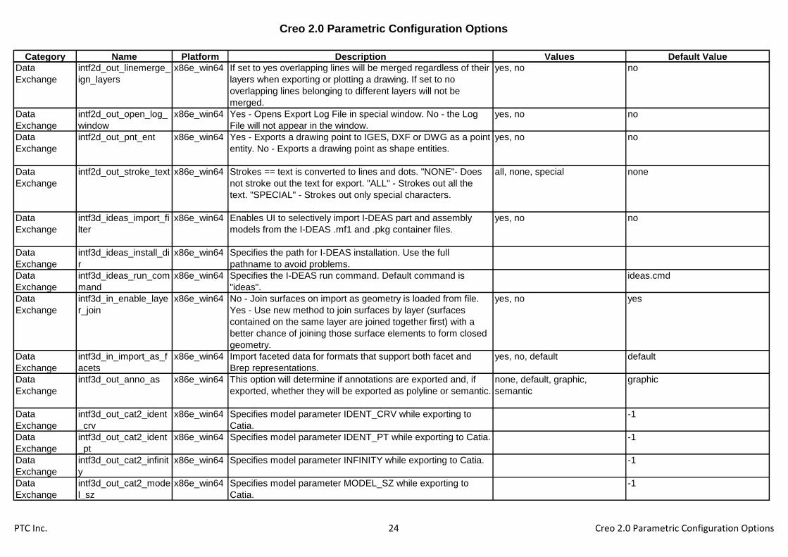
intf2d_out_linemerge_
ign_layers
x86e_win64 If set to yes overlapping lines will be merged regardless of their
layers when exporting or plotting a drawing. If set to no
overlapping lines belonging to different layers will not be
merged.
yes, no no
Data
Exchange
intf2d_out_open_log_
window
x86e_win64 Yes - Opens Export Log File in special window. No - the Log
File will not appear in the window.
yes, no no
Data
Exchange
intf2d_out_pnt_ent x86e_win64 Yes - Exports a drawing point to IGES, DXF or DWG as a point
entity. No - Exports a drawing point as shape entities.
yes, no no
Data
Exchange
intf2d_out_stroke_text x86e_win64 Strokes == text is converted to lines and dots. "NONE"- Does
not stroke out the text for export. "ALL" - Strokes out all the
text. "SPECIAL" - Strokes out only special characters.
all, none, special none
Data
Exchange
intf3d_ideas_import_fi
lter
x86e_win64 Enables UI to selectively import I-DEAS part and assembly
models from the I-DEAS .mf1 and .pkg container files.
yes, no no
Data
Exchange
intf3d_ideas_install_di
r
x86e_win64 Specifies the path for I-DEAS installation. Use the full
pathname to avoid problems.
Data
Exchange
intf3d_ideas_run_com
mand
x86e_win64 Specifies the I-DEAS run command. Default command is
"ideas".
ideas.cmd
Data
Exchange
intf3d_in_enable_laye
r_join
x86e_win64 No - Join surfaces on import as geometry is loaded from file.
Yes - Use new method to join surfaces by layer (surfaces
contained on the same layer are joined together first) with a
better chance of joining those surface elements to form closed
geometry.
yes, no yes
Data
Exchange
intf3d_in_import_as_f
acets
x86e_win64 Import faceted data for formats that support both facet and
Brep representations.
yes, no, default default
Data
Exchange
intf3d_out_anno_as x86e_win64 This option will determine if annotations are exported and, if
exported, whether they will be exported as polyline or semantic.
none, default, graphic,
semantic
graphic
Data
Exchange
intf3d_out_cat2_ident
_crv
x86e_win64 Specifies model parameter IDENT_CRV while exporting to
Catia.
-1
Data
Exchange
intf3d_out_cat2_ident
_pt
x86e_win64 Specifies model parameter IDENT_PT while exporting to Catia. -1
Data
Exchange
intf3d_out_cat2_infinit
y
x86e_win64 Specifies model parameter INFINITY while exporting to Catia. -1
Data
Exchange
intf3d_out_cat2_mode
l_sz
x86e_win64 Specifies model parameter MODEL_SZ while exporting to
Catia.
-1
PTC Inc. 24 Creo 2.0 Parametric Configuration Options

Creo 2.0 Parametric Configuration Options
Category Name Platform Description Values Default Value
Data
Exchange
intf3d_out_cat2_sag x86e_win64 Specifies model parameter SAG while exporting to Catia. -1
Data
Exchange
intf3d_out_cat2_step x86e_win64 Specifies model parameter STEP while exporting to Catia. -1
Data
Exchange
intf3d_out_datums_by
_default
x86e_win64 Determines whether datum curves are included when exporting
IGES files in Batch mode.
yes, no no
Data
Exchange
intf3d_out_default_opt
ion
x86e_win64 Controls the type of 3-D data output through Pro/BATCH to an
IGES or STEP file.
none, wireframe, surfaces,
wireframe_surfaces, solid,
shells
surfaces
Data
Exchange
intf3d_out_extend_sur
face
x86e_win64 Specifies how surfaces are handled for exporting files to other
systems
yes, no yes
Data
Exchange
intf3d_out_force_surf
_normals
x86e_win64 IGES and PDGS export. Controls normals of non-analytic
surfaces. Yes - Forces the surface normals to point in a
consistent direction. No - Does not force the surface normals to
point in a consistent direction.
yes, no no
Data
Exchange
intf3d_out_jt_auto_lod
s
x86e_win64 Generate three default Creo Parametric LODs. yes, no no
Data
Exchange
intf3d_out_jt_brep x86e_win64 No*: Export to JT as facet representation only, jt_brep: Export
to JT as facet and jt_brep representation, xt_brep: Export to JT
as facet and xt_brep representation
no, jt_brep, xt_brep no
Data
Exchange
intf3d_out_jt_structure x86e_win64 Specifies product structure to file structure mapping defined in
JT Open Toolkit.
per_part, fully_shattered,
monolithic
per_part
Data
Exchange
intf3d_out_parameter
s
x86e_win64 Exports parameters with models. all, none, designated all
Data
Exchange
intf3d_out_prop_chor
d_heights
x86e_win64 Use maximum chord heights proportional to component sizes. yes, no no
Data
Exchange
intf3d_out_prop_step
_sizes
x86e_win64 Use maximum step sizes proportional to component sizes. yes, no no
Data
Exchange
intf3d_out_surface_de
viation
x86e_win64 Sets maximum allowable deviation between original and
resulting surfaces in the process of converting Creo Parametric
surfaces to spline surfaces. By setting this you convert
surfaces with a better approximation than by using the current
model accuracy.
-1
Data
Exchange
intf3d_out_unicode_to
_neutral
x86e_win64 YES - Unicode strings are exported to the Neutral file, NO -
Unicode strings are converted to ascii characters for Neutral
file export.
yes, no yes
Data
Exchange
intf3d_out_use_num_
names
x86e_win64 Use numeric layer names as layer export IDs. yes, no yes
PTC Inc. 25 Creo 2.0 Parametric Configuration Options

Creo 2.0 Parametric Configuration Options
Category Name Platform Description Values Default Value
Data
Exchange
intf3d_out_use_step_
size
x86e_win64 Use maximum step size(s). yes, no no
Data
Exchange
intf3d_parasolid_expo
rt_schema
x86e_win64 Allows user to choose the schema to be used for parasolid
export. Default is SCH_10004. Consult online documentation
for other valid schema settings.
sch_10004
Data
Exchange
medusa_2d_config_fil
e
x86e_win64 Specifies the Medusa 2D Interface config. file. Absolute or
relative path to the file can be used.
Data
Exchange
mentor_ver_2_0 x86e_win64 Yes - Exports the file in IDF 2.0 format. No - Exports the file in
IDF 1.0 format unless IDF 2.0 is selected from the ECAD
FORMAT menu.
yes, no yes
Data
Exchange
pdf_linecap x86e_win64 0 - Butt cap: stroked lines are squared off at the endpoint of the
path. There is no projection beyond the end of the path.
butt, round, projecting square butt
Data
Exchange
pdf_linejoin x86e_win64 0 - Miter join: outer edges of the strokes for the two segments
are extended until they meet at an angle.
round, miter, bevel miter
Data
Exchange
pdf_use_pentable x86e_win64 No - PDF export does not use any defined pentable changes
as would be applied to plotting the drawing.
yes, no no
Data
Exchange
pro_gplug_dir x86e_win64 Specifies the directory in which Granite application plug-ins are
located. Use the full pathname to avoid problems.
<creo_loadpoint>\x86e_win64\gpl
ugs\
Data
Exchange
pro_stheno_comman
d
x86e_win64 Specifies the command for Stheno launch.
Data
Exchange
put_iges_drawing_ent
ity
x86e_win64 Specifies whether or not to suppress the output of the IGES
drawing entity, #404, to the IGES file. No - The drawing entity is
not output.
yes, no yes
Data
Exchange
step_appearance_lay
ers_groups
x86e_win64 No - Output of Appearances, Layers, and Groups is enabled
for STEP standard AP214. Yes - Output of Appearances,
Layers, and Groups is enabled for STEP standard AP203.
yes, no no
Data
Exchange
step_export_ap214_a
sm_def_mode
x86e_win64 Toggles the default setting of the File Structure field in the
STEP Export dialog box for supported assembly STEP export
files.
single_file,
separate_parts_only,
separate_all_objects
single_file
Data
Exchange
step_export_dwg_vie
ws
x86e_win64 AS_3D_VIEWS - Export 3-D model geometry with its
associative views. AS_3D_VIEWS_ASSOC_DRAFT - Export 3-
D model geometry with its associative views and view related
annotations. NO - Export only 2-D representations of the 3-D
models. This is the default.
no, as_3d_views,
as_3d_views_assoc_draft
no
PTC Inc. 26 Creo 2.0 Parametric Configuration Options

Creo 2.0 Parametric Configuration Options
Category Name Platform Description Values Default Value
Data
Exchange
step_export_format x86e_win64 Specifies output format when exporting to STEP. AP203_IS -
Formats output to ISO 10303 AP203IS format. AP214_CD -
Formats output with geometry that meets the specification for
the long-term schema for AP214cc1.
ap203_is, ap202_is,
ap209_dis, ap214_is,
ap203_e2, ap203_is_ext
ap203_is
Data
Exchange
step_out_asm_val_pr
op
x86e_win64 Export validation information for assemblies to the STEP file for
formats ap203_e2, ap214_is
yes, no no
Data
Exchange
step_out_material x86e_win64 Exports the material definition (name and density) to the STEP
file for formats ap203_e2, ap214_is and 203_is_ext
yes, no no
Data
Exchange
step_out_material_as
_product
x86e_win64 Export the material definition (name and density) to the STEP
file as a separate STEP PRODUCT entity
yes, no no
Data
Exchange
step_out_suppl_geom x86e_win64 Export datum csys, planes, axes, points to the STEP file for
formats ap203_e2, ap214_is
yes, no no
Data
Exchange
system_iges_header_
file
x86e_win64 Inserts specified text file into the Start section of IGES files
(refer to user_iges_header_file). When used with
user_iges_header_file, the system text appears first.
Data
Exchange
template_boardpart x86e_win64 Specify the model to use as the default new ECAD board
template.
Data
Exchange
template_new_ecada
sm
x86e_win64 Specify the model to use as the default new ECAD assembly
template.
Data
Exchange
tiff_compression x86e_win64 TIFF exports are done without compression. none, g4, packbits, deflate none
Data
Exchange
tiff_type x86e_win64 Determines the type of tiff items are exported to variables refer
to color sets
rgb, palette, grayscale, mono rgb
Data
Exchange
use_export_2d_dialog x86e_win64 Yes - Opens export options dialog when exporting Creo
Parametric drawing. No - exports file without the options dialog.
yes, no yes
Data
Exchange
use_iges_font_1003 x86e_win64 Used to disable the use of IGES font 1003. yes, no yes
Data
Exchange
use_iges_kanji_font_
2001
x86e_win64 Specifies whether to convert Kanji notes in Creo Parametric to
IGES Kanji notes (font code) when exporting. Yes - Converts
Kanji notes to IGES Kanji notes. No - Converts using Font 1.
yes, no no
Data
Exchange
user_iges_header_file x86e_win64 Filename - Insert specified text file into the Start section of
IGES file. Valid parametric note symbols will be replaced
during export. For example, &dwg_name in the text file is
replaced by the drawing name when a drawing is exported.
PTC Inc. 27 Creo 2.0 Parametric Configuration Options

Creo 2.0 Parametric Configuration Options
Category Name Platform Description Values Default Value
Data
Exchange
vda_header x86e_win64 The complete filename of the text file containing VDA header
information. If you intend to use the same header for all VDA
files, specify the full pathname.
Data
Exchange
vrml_anchor_url x86e_win64 Enables you to place an anchor on a specified VRML
component during the export to VRML. The keywords are
optional.
Data
Exchange
vrml_background_col
or
x86e_win64 Yes - Exports a model to VRML with the Creo Parametric
background color.
yes, no no
Data
Exchange
vrml_explode_lines x86e_win64 Yes - Exports a model to VRML with explode lines for
assembly or assembly process data.
yes, no yes
Data
Exchange
vrml_export_resolutio
n
x86e_win64 Specifies the number of levels of detail (LODs) in models
exported in VRML format.
high, medium, low medium
Data
Exchange
vrml_export_version x86e_win64 Allows the user to choose between exporting to the VRML 2.0
or 1.0 format.
2.0, 1.0 2
Data
Exchange
vrml_file_duplicate_m
aterial
x86e_win64 Yes - Ensures that the model components retain their true
color. No - In some viewers, component colors might not be
consistent.
yes, no no
Data
Exchange
vrml_multiple_views x86e_win64 All - Exports top-level and lower-level assembly component
views into VRML format. None - Does not export component
views into VRML format. Top - Exports top-level object view
only into VRML format.
all, none, top all
Data
Exchange
vrml_parameters x86e_win64 Controls the export of user parameters. Designated - Export
only designated parameters. All - Export all parameters. None -
Do not export parameters.
all, none, designated designated
Data
Exchange
vrml_simprep_export x86e_win64 Yes - Specifies direct and in memory export of top-level
assembly simplified representation to Pro/FLY-THROUGH
package files.
yes, no no
Data
Exchange
www_add_aux_frame x86e_win64 Creates additional frame for each process step or for assembly
publication. Yes - Auxiliary files aux.html are created for each
step in assembly process (in each step00 directory) to be
replaced by your .html file. No - Auxiliary files are not created.
yes, no no
Data
Exchange
www_export_geometr
y_as
x86e_win64 Specifies the output format by to one of the values all, vrml, cgm, jpg, cgm_vrml,
jpg_vrml, cgm_jpg
jpg_vrml
PTC Inc. 28 Creo 2.0 Parametric Configuration Options
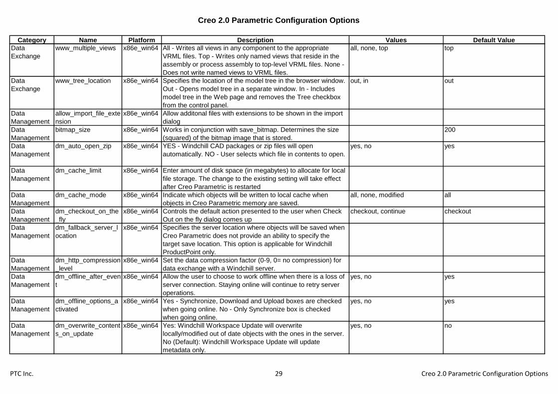
Creo 2.0 Parametric Configuration Options
Category Name Platform Description Values Default Value
Data
Exchange
www_multiple_views x86e_win64 All - Writes all views in any component to the appropriate
VRML files. Top - Writes only named views that reside in the
assembly or process assembly to top-level VRML files. None -
Does not write named views to VRML files.
all, none, top top
Data
Exchange
www_tree_location x86e_win64 Specifies the location of the model tree in the browser window.
Out - Opens model tree in a separate window. In - Includes
model tree in the Web page and removes the Tree checkbox
from the control panel.
out, in out
Data
Management
allow_import_file_exte
nsion
x86e_win64 Allow additonal files with extensions to be shown in the import
dialog
Data
Management
bitmap_size x86e_win64 Works in conjunction with save_bitmap. Determines the size
(squared) of the bitmap image that is stored.
200
Data
Management
dm_auto_open_zip x86e_win64 YES - Windchill CAD packages or zip files will open
automatically. NO - User selects which file in contents to open.
yes, no yes
Data
Management
dm_cache_limit x86e_win64 Enter amount of disk space (in megabytes) to allocate for local
file storage. The change to the existing setting will take effect
after Creo Parametric is restarted
Data
Management
dm_cache_mode x86e_win64 Indicate which objects will be written to local cache when
objects in Creo Parametric memory are saved.
all, none, modified all
Data
Management
dm_checkout_on_the
_fly
x86e_win64 Controls the default action presented to the user when Check
Out on the fly dialog comes up
checkout, continue checkout
Data
Management
dm_fallback_server_l
ocation
x86e_win64 Specifies the server location where objects will be saved when
Creo Parametric does not provide an ability to specify the
target save location. This option is applicable for Windchill
ProductPoint only.
Data
Management
dm_http_compression
_level
x86e_win64 Set the data compression factor (0-9, 0= no compression) for
data exchange with a Windchill server.
Data
Management
dm_offline_after_even
t
x86e_win64 Allow the user to choose to work offline when there is a loss of
server connection. Staying online will continue to retry server
operations.
yes, no yes
Data
Management
dm_offline_options_a
ctivated
x86e_win64 Yes - Synchronize, Download and Upload boxes are checked
when going online. No - Only Synchronize box is checked
when going online.
yes, no yes
Data
Management
dm_overwrite_content
s_on_update
x86e_win64 Yes: Windchill Workspace Update will overwrite
locally/modified out of date objects with the ones in the server.
No (Default): Windchill Workspace Update will update
metadata only.
yes, no no
PTC Inc. 29 Creo 2.0 Parametric Configuration Options

Creo 2.0 Parametric Configuration Options
Category Name Platform Description Values Default Value
Data
Management
dm_remember_server x86e_win64 Primary server/workspace must be set by user for each Creo
Parametric session.
yes, no yes
Data
Management
dm_save_as_attachm
ent
x86e_win64 Controls the default option for Save A Copy when models are
saved as in non-Creo Parametric format. Yes - It will by default
save it as secondary content attachment to the original CAD
Document. No- It will by default save it as Primary CAD
Document
yes, no yes
Data
Management
dm_search_primary_s
erver
x86e_win64 Search the primary server for dependencies not found in the
workspace.
yes, no yes
Data
Management
dm_secondary_uploa
d
x86e_win64 Indicate when modified Creo Parametric objects on a
secondary server will be moved from the local cache to the
user's workspace on the server.
automatic, explicit automatic
Data
Management
dm_simple x86e_win64 Activate Simple Windchill Interaction yes, no no
Data
Management
dm_synchronize_in_b
ackground
x86e_win64 Yes: Enables workspace synchronization in the background.
No (Default): Workspace synchronization will happen in the
foreground.
yes, no no
Data
Management
dm_upload_objects x86e_win64 Indicate when modified Creo Parametric objects will be moved
from the local cache to the user workspace on the server.
automatic, explicit explicit
Data
Management
dm_user_presence x86e_win64 Enable user presence indicator and actions. This capability
requires a connection with a PDM server and requires an
installed and running Microsoft communicator client.
yes, no yes
Data
Management
let_proe_rename_pd
m_objects
x86e_win64 Determines whether an object fetched from a PDM database
can be renamed in a Creo Parametric session.
yes, no no
Data
Management
pdm_rev x86e_win64 Specify how the system parameter, PDM_REV, should be
formatted. Only useful for objects submitted to Pro/PDM or
Pro/INTRALINK.
pdmrev_fmt_rev_ver,
pdmrev_fmt_rev,
pdmrev_fmt_branch_rev_ver,
pdmrev_fmt_branch_rev
pdmrev_fmt_rev_ver
Data
Management
read_parameters_of_
excluded
x86e_win64 Allow Creo Parametric designated parameters on excluded
objects in Simplified Representation to be visible in Model Tree
columns.
yes, no, common_name_only no
Data
Management
regenerate_read_only
_objects
x86e_win64 Determines whether an object retrieved from PDM database
with read only status can be regenerated in a Creo Parametric
session.
yes, no yes
PTC Inc. 30 Creo 2.0 Parametric Configuration Options

Creo 2.0 Parametric Configuration Options
Category Name Platform Description Values Default Value
Data
Management
save_bitmap x86e_win64 When performing a save on a model, determines what level of
the assembly will have bitmap images created of modified
components.
none, toplevelonly, alllevels none
Data
Management
save_bitmap_type x86e_win64 When performing a save on a model, determines the type of
image file that is created for that model. Used with
"save_bitmap" option.
cgm, bmp, tiff, gif, jpeg bmp
Data
Management
save_unchanged_pd
m_object
x86e_win64 Determines how to save in the current working directory an
object fetched from a Pro/PDM database into a Creo
Parametric session.
as_ref, as_copy as_ref
Design
Manager
dont_show_symbol_n
odes
x86e_win64 Do not show references derived from relations in Parent/Child
viewer.
yes, no no
Dimensions &
Tolerances
allow_rfs_default_gtol
s_always
x86e_win64 Yes - Enables RFS/Default gtols to be created even when not
permitted by ANSI standard.
yes, no no
Dimensions &
Tolerances
ang_dim_in_screen x86e_win64 Yes - If the display is in the default pan/zoom setting
(View>Pan/Zoom>Reset), the system checks whether an
angular dimension is visible on the screen. If it is not visible,
then the system moves the dimension to a visible location.
yes, no no
Dimensions &
Tolerances
angular_tol x86e_win64 An alternative format for setting default angular tolerance
dimensions. The value sets the number of decimal places, and
the tolerance is the actual tolerance value. For integer
dimensions, the value is zero, and the tolerance is an integer.
0
Dimensions &
Tolerances
angular_tol_0.0 x86e_win64 Sets the default tolerance for angular dimensions. Each option
sets a tolerance for a specific decimal place. The value is the
place of the last decimal.
5
Dimensions &
Tolerances
angular_tol_0.00 x86e_win64 Sets the default tolerance for angular dimensions. Each option
sets a tolerance for a specific decimal place. The value is the
place of the last decimal.
50
Dimensions &
Tolerances
angular_tol_0.000 x86e_win64 Sets the default tolerance for angular dimensions. Each option
sets a tolerance for a specific decimal place. The value is the
place of the last decimal.
500
Dimensions &
Tolerances
angular_tol_0.0000 x86e_win64 Sets the default tolerance for angular dimensions. Each option
sets a tolerance for a specific decimal place. The value is the
place of the last decimal.
5000
Dimensions &
Tolerances
angular_tol_0.00000 x86e_win64 Sets the default tolerance for angular dimensions. Each option
sets a tolerance for a specific decimal place. The value is the
place of the last decimal.
50000
PTC Inc. 31 Creo 2.0 Parametric Configuration Options

Creo 2.0 Parametric Configuration Options
Category Name Platform Description Values Default Value
Dimensions &
Tolerances
angular_tol_0.000000 x86e_win64 Sets the default tolerance for angular dimensions. Each option
sets a tolerance for a specific decimal place. The value is the
place of the last decimal.
500000
Dimensions &
Tolerances
create_fraction_dim x86e_win64 Yes - All dimensions created will be displayed as fractions. yes, no no
Dimensions &
Tolerances
default_ang_units x86e_win64 Sets the display of newly created angular dimensions both in
the model and in the drawing. There is no impact on
dimensions previously created. ang_deg - Decimal degrees.
ang_min - Degrees and decimal minutes ang_sec - Degrees,
minutes, and decimal seconds
ang_deg, ang_min, ang_sec ang_deg
Dimensions &
Tolerances
default_dec_places x86e_win64 Sets the default number of decimal places (0-13) to which to
round newly created dimensions. Unrounded dimensions
automatically determine the number of decimal places required
to display their stored value.
2
Dimensions &
Tolerances
default_dim_num_digi
ts_changes
x86e_win64 Sets the default number of digits displayed in a dimension to
the last entered value. No - The system defaults to the value
specified for the configuration file option default_dec_places.
yes, no yes
Dimensions &
Tolerances
default_placement_su
rfacefinish
x86e_win64 Sets the default placement type for surface finishes within the
surface finish UI.
with_leaders, on_entity,
normal_to_entity, free
normal_to_entity
Dimensions &
Tolerances
dim_fraction_denomin
ator
x86e_win64 Sets the largest denominator to be used for fractional
dimensions. If the fraction can be reduced, then it converts to
the lowest possible denominator (for example, 4/32 converts to
1/8).
32
Dimensions &
Tolerances
dim_fraction_format x86e_win64 Std - Displays fractional dimensions in the standard Creo
Parametric format. Aisc - Displays fractional dimensions in the
American Institute of Steel Construction (AISC) format and
displays architectural units in AISC format for feet-inches.
std, aisc std
Dimensions &
Tolerances
dim_offscreen_limit x86e_win64 If more than zero, sets the margin beyond which dimensions
are automatically snapped back onto the screen. For example,
a value of .2 lets a dimension be 20% of the window size
outside the window. If set to zero, disables snapping of
offscreen dimensions.
0.2
Dimensions &
Tolerances
display_tol_by_1000 x86e_win64 If set to Yes, tolerances for non-angular dimensions will be
displayed multiplied by 1000.
yes, no no
PTC Inc. 32 Creo 2.0 Parametric Configuration Options
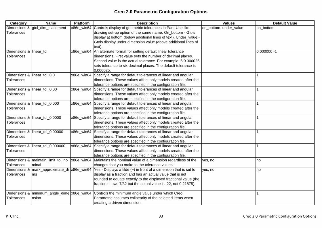
Creo 2.0 Parametric Configuration Options
Category Name Platform Description Values Default Value
Dimensions &
Tolerances
gtol_dim_placement x86e_win64 Controls display of geometric tolerances in Part. Use like
drawing set-up option of the same name. On_bottom - Gtols
display at bottom (below additional lines of text). Under_value -
Gtols display under dimension value (above additional lines of
text).
on_bottom, under_value on_bottom
Dimensions &
Tolerances
linear_tol x86e_win64 An alternate format for setting default linear tolerance
dimensions. First value sets the number of decimal places.
Second value is the actual tolerance. For example, 6 0.000025
sets tolerance to six decimal places. The default tolerance is
0.000025.
0.000000 -1
Dimensions &
Tolerances
linear_tol_0.0 x86e_win64 Specify a range for default tolerances of linear and angular
dimensions. These values affect only models created after the
tolerance options are specified in the configuration file.
1
Dimensions &
Tolerances
linear_tol_0.00 x86e_win64 Specify a range for default tolerances of linear and angular
dimensions. These values affect only models created after the
tolerance options are specified in the configuration file.
1
Dimensions &
Tolerances
linear_tol_0.000 x86e_win64 Specify a range for default tolerances of linear and angular
dimensions. These values affect only models created after the
tolerance options are specified in the configuration file.
1
Dimensions &
Tolerances
linear_tol_0.0000 x86e_win64 Specify a range for default tolerances of linear and angular
dimensions. These values affect only models created after the
tolerance options are specified in the configuration file.
1
Dimensions &
Tolerances
linear_tol_0.00000 x86e_win64 Specify a range for default tolerances of linear and angular
dimensions. These values affect only models created after the
tolerance options are specified in the configuration file.
1
Dimensions &
Tolerances
linear_tol_0.000000 x86e_win64 Specify a range for default tolerances of linear and angular
dimensions. These values affect only models created after the
tolerance options are specified in the configuration file.
1
Dimensions &
Tolerances
maintain_limit_tol_no
minal
x86e_win64 Maintains the nominal value of a dimension regardless of the
changes that you make to the tolerance values.
yes, no no
Dimensions &
Tolerances
mark_approximate_di
ms
x86e_win64 Yes - Displays a tilde (~) in front of a dimension that is set to
display as a fraction and has an actual value that is not
rounded to equate exactly to the displayed fractional value (the
fraction shows 7/32 but the actual value is .22, not 0.21875).
yes, no no
Dimensions &
Tolerances
minimum_angle_dime
nsion
x86e_win64 Controls the minimum angle value under which Creo
Parametric assumes colinearity of the selected items when
creating a driven dimension.
1
PTC Inc. 33 Creo 2.0 Parametric Configuration Options

Creo 2.0 Parametric Configuration Options
Category Name Platform Description Values Default Value
Dimensions &
Tolerances
parenthesize_ref_dim x86e_win64 Encloses reference dimensions in parentheses. No - Follows
reference dimensions with the text "REF".
yes, no no
Dimensions &
Tolerances
restricted_gtol_dialog x86e_win64 Determines whether the Geometric Tolerance dialog restricts
the user by graying out elements that are considered "illegal".
yes, no yes
Dimensions &
Tolerances
round_displayed_dim
_values
x86e_win64 Sets the default status of the Round Displayed Value checkbox
for new and newly shown dimensions.
yes, no yes
Dimensions &
Tolerances
tbl_driven_tol_val_edit x86e_win64 Tbl_driven_tol_val_edit Y/N* - "Yes" allows users to directly edit
the tolerance value of dimensions whose tolerance values are
driven by tolerance tables. Editing the tolerance value of a
dimension will make the dimension non-table-driven. "No"
disallows direct editing of the tolerance values of table driven
tolerances.
yes, no no
Dimensions &
Tolerances
tol_display x86e_win64 Displays dimensions with or without tolerances. yes, no no
Dimensions &
Tolerances
tolerance_class x86e_win64 Sets the default tolerance class for ISO-standard models. The
system uses the tolerance class in conjunction with the
dimension value when retrieving tolerances for General or
Broken Edge dimensions.
medium, fine, coarse,
very_coarse
Dimensions &
Tolerances
tolerance_standard x86e_win64 Sets the tolerance standard used when creating the model. ansi, iso ansi
Dimensions &
Tolerances
tolerance_table_dir x86e_win64 Sets the default directory for user-defined tolerance tables for
ISO-standard models. All Holes and Shafts tables overwrite
existing tables when loaded.
Dimensions &
Tolerances
use_major_units x86e_win64 Determines if fractional dimensions are displayed in terms of
feet-inches or meter-mm. Yes - The major units are used. For
example, when the units are inches and 25.125 is converted to
a fraction, the dimension becomes 2' 1-1/8".
yes, no no
Dimensions &
Tolerances
use_nom_dim_val_in
_expr
x86e_win64 Yes - use dimensions' nominal values in expressions. No - use
current values.
yes, no no
Drawing allow_move_attach_in
_dtl_move
x86e_win64 Yes - Move and Move Attach commands in drawing mode act
together. No - Move and Move Attach commands in drawing
mode do not act together.
yes, no yes
Drawing allow_move_view_wit
h_move
x86e_win64 Disallow the movement of drawing views with the mouse. yes, no no
PTC Inc. 34 Creo 2.0 Parametric Configuration Options

Creo 2.0 Parametric Configuration Options
Category Name Platform Description Values Default Value
Drawing allow_refs_to_geom_r
eps_in_drws
x86e_win64 Yes - Allows you to create drawing references to geometry
representations (includes dimensions, notes, and leaders).
These references may become invalid if the referenced
geometry changes resulting in geometry representations not
updating in drawings.
yes, no no
Drawing auto_constr_offset_tol
erance
x86e_win64 Sets the auto constraint tolerance for creating offset
dimensions. If distance is less than this tolerance multiplied by
component size, offset is set as coincident. Default value is 0.5
.
0.5
Drawing auto_regen_views x86e_win64 Yes - Automatically repaints the drawing display when
changing from one window to another. No - Update to drawing
views will only occur when manual updates are made via
Repaint or View> Update.
yes, no yes
Drawing autobuildz_enabled x86e_win64 Loads AutobuildZ application. yes, no no
Drawing bom_format x86e_win64 Sets the BOM format file to be used for a customized BOM.
Specify name and path.
<creo_loadpoint>\text\format.bft
Drawing create_drawing_dims
_only
x86e_win64 Yes - Saves all new driven dimensions created in the drawing
inside the drawing as associative draft dimensions. No - Saves
driven dimensions created in Drawing mode on solid geometry
in the solid.
yes, no no
Drawing default_ang_dec_plac
es
x86e_win64 Sets the default number of decimal places (0-13) to which to
round newly created angular dimensions. Unrounded angular
dimensions automatically determine the number of decimal
places required to display their stored value.
1
Drawing default_draw_scale x86e_win64 Sets the default drawing scale for views added with the No
Scale command. The value must be greater than 0. No - The
system does not set a default drawing scale.
-1
Drawing default_font_kerning_i
n_drawing
x86e_win64 Determines initial setting of Font kerning when 2D drawing
annotations are created. Yes - Font kerning is on for new 2D
annotations.
yes, no no
Drawing disp_trimetric_dwg_m
ode_view
x86e_win64 Displays the model in default orientation when placing a
general view on the drawing. No - Model does not appear until
Default is chosen from the Orientation dialog box.
yes, no yes
Drawing display_dwg_sketch_
constraint
x86e_win64 When set to yes, parametric sketching constraints, such as V
for vertical, are displayed when a drawing object is selected
yes, no no
PTC Inc. 35 Creo 2.0 Parametric Configuration Options

Creo 2.0 Parametric Configuration Options
Category Name Platform Description Values Default Value
Drawing display_dwg_tol_tags x86e_win64 Sets the display of the tolerance tags that appear in drawings.
This option does not affect the display of tolerances on
dimensions.
yes, no yes
Drawing display_in_adding_vie
w
x86e_win64 Controls model display in a drawing when auto_regen_views is
No. Wireframe - Adds new views in wireframe, displays
datums. Minimal_wireframe - Displays in wireframe, no
datums, axes, or silhouette edges. Default - Displays using the
Environment setting.
default, wireframe,
minimal_wireframe
wireframe
Drawing draw_models_read_o
nly
x86e_win64 Yes - Drawing model files are read-only. No model changes
can be made. Cosmetic_only - Only cosmetic changes can be
made to the model. Design changes are not allowed.
Cosmetic changes include adding driven dimensions, cross
sections, and explode states.
yes, no, cosmetic_only no
Drawing draw_points_in_mode
l_units
x86e_win64 Defines the current draft view's coordinate values as model
units rather than drawing units. The GET POINT menu uses
the scale of the draft view and the draft view's model units for
relative and absolute coordinate entry and display in the
Message Window.
yes, no no
Drawing drawing_ole_image_d
pi
x86e_win64 Resolution of OLE object images. The range of valid values is
0 to 600 dots per inch.
150
Drawing drawing_setup_file x86e_win64 Sets the default drawing setup file option values for your Creo
Parametric session, otherwise, the system uses the default
drawing setup file option values. Certain parameters in the file
are valid only if you have a license for Pro/DETAIL.
<creo_loadpoint>\text\prodetail.dtl
Drawing drawing_shaded_view
_dpi
x86e_win64 Resolution of exported shaded drawing views. The range of
valid values is 0 to 600 dots per inch.
150
Drawing drawing_view_origin_
csys
x86e_win64 The named coordinate system will be used as the origin of a
newly created view or of a modified view. None - The system
will not use a previously specified coordinate system.
none
Drawing drawing_warn_if_flex
_feature
x86e_win64 Display a warning dialog upon opening a drawing with models
that contain flexible features advising users that annotations
may be out of date and should be verified.
yes, no yes
PTC Inc. 36 Creo 2.0 Parametric Configuration Options

Creo 2.0 Parametric Configuration Options
Category Name Platform Description Values Default Value
Drawing dwg_unicode_conver
sion_language
x86e_win64 Defines the language used during Unicode conversion of pre-
Wildfire 4.0 drawings. This option does not affect the
conversion of models. File - Uses the language stored in the
drawing header file; Session - Uses the language of the current
Creo Parametric session.
file, session, english, japanese,
french, german, russian,
italian, spanish, korean,
chinese_tw, chinese_cn,
hebrew, greek, turkish, czech,
polish, hungarian, slovenian,
portuguese, slovak, usascii
file
Drawing enable_shaded_view_
in_drawings
x86e_win64 Yes - shading display is allowed in drawing views. No - shading
display will be shown in wireframe.
yes, no yes
Drawing force_wireframe_in_d
rawings
x86e_win64 Yes - Displays all views of drawings in wireframe. No - Displays
views according to the display set for the session (wireframe,
hidden, and so on).
yes, no no
Drawing format_setup_file x86e_win64 Assigns a specified setup file to each drawing format. To
assign the drawing's parameter values to the format, you must
retrieve the drawing's setup file into the format.
dwgform.dtl
Drawing highlight_erased_dwg
_views
x86e_win64 Controls the display of erased view outlines (environment
option Highlight Erased Views). Yes - Highlights erased views.
No - Turns off highlighting for erased views.
yes, no yes
Drawing highlight_new_dims x86e_win64 In drawing mode, highlights new dimensions in red until you
repaint the screen.
yes, no no
Drawing hlr_for_quilts x86e_win64 In Drawing, controls quilt display in hidden line removal. Yes -
Includes quilts in the hidden line removal process (preselects
Qlt HLR in the VIEW DISP menu). Default in the VIEW DISP
menu, uses the value you have set.
yes, no no
Drawing make_aux_view_note
s
x86e_win64 Automatically adds view names to auxiliary views using AUX
VIEW* viewname-viewname. You can modify the view name
after adding the view to the drawing.
yes, no no
Drawing make_parameters_fro
m_fmt_tables
x86e_win64 Determines the handling of values entered in a format table
when you replace one drawing format with another. Yes -
Stores entered values for format table and copies them with
the table. No - Prompts you to re-enter all the values for the
format table.
yes, no no
Drawing make_proj_view_note
s
x86e_win64 Automatically adds view names to projection views in the
format "VIEW viewname-viewname." You can modify the view
name after adding the view to the drawing.
yes, no no
PTC Inc. 37 Creo 2.0 Parametric Configuration Options

Creo 2.0 Parametric Configuration Options
Category Name Platform Description Values Default Value
Drawing pick_chain_tangent_o
nly
x86e_win64 Specifies the extent of draft entity chains selected. Yes - Only
entities in the chain that are tangent will be selected. No - All
entities connected end to end will be selected.
yes, no no
Drawing preferred_export_for
mat
x86e_win64 Set the default preferred export file type for export from
drawings.
cgm, tiff, iges, dxf, step, pdf,
dwg, medusa, stheno
Drawing pro_dtl_setup_dir x86e_win64 Sets the directory for the drawing setup files. If this option is not
set, the system uses the default setup directory.
Drawing pro_format_dir x86e_win64 Sets the default directory for the drawing format library. Use the
full pathname to avoid problems.
Drawing pro_note_dir x86e_win64 Specifies the directory from which to retrieve notes entered
from a file. Use the full path name to avoid problems.
<dir_name>\dump_x86e_win64\
Drawing pro_palette_dir x86e_win64 Sets the default directory for drawing symbol palette files. <creo_loadpoint>\symbols\palette
\
Drawing pro_symbol_dir x86e_win64 Set and automatically create the default directory for saving
and retrieving user-defined symbols. If you do not specify a
directory, the system uses the current working directory. Use
full path name to avoid problems.
<dir_name>\dump_x86e_win64\
Drawing pro_table_dir x86e_win64 Specifies the directory to be used when tables are retrieved or
saved. Use the full path name to avoid problems.
Drawing remember_last_get_p
oint_option
x86e_win64 Yes - Sets the default of the GET POINT menu as the last
option picked among Pick Pnt, Vertex and On Entity.
yes, no no
Drawing save_display x86e_win64 Yes - Stores view geometry and detail items such as solid
dimensions. These items are displayed when retrieving the
drawing in View-Only mode.
yes, no no
Drawing save_drawing_picture
_file
x86e_win64 Embed - Embeds a picture file inside a drawing for preview
purposes. Export - Saves a drawing file as a picture file in the
working directory when saving a drawing. Both - Does both
embed and export.
no, export, embed, both embed
Drawing save_modified_draw_
models_only
x86e_win64 Determines whether the system saves the model after you
have changed it. No - Saves the model every time that you
store the drawing.
yes, no yes
Drawing select_hidden_edges
_in_dwg
x86e_win64 Controls selectability of hidden edges in no-hidden drawing
views.
yes, no yes
PTC Inc. 38 Creo 2.0 Parametric Configuration Options

Creo 2.0 Parametric Configuration Options
Category Name Platform Description Values Default Value
Drawing selection_of_removed
_entities
x86e_win64 Yes - Entities in front of cross-section (planar or offset) can be
selected, clipped (using Z-clipping), or erased with EDGE DISP
menu. No - Geometry, datum points or curves, cosmetic
features, threads, grooves, or coordinate systems cannot be
erased.
yes, no no
Drawing show_annotations_dia
log_limit
x86e_win64 Default value for Annotations dialog box.
Drawing show_preview_default x86e_win64 This option determines the default behavior for preview in
Show/Erase.
remove, keep remove
Drawing switch_dims_for_note
s
x86e_win64 Yes - Dimensions will be displayed in their symbolic format
during drawing note creation. No - Dimensions will be displayed
in drawing notes as numerical values.
yes, no yes
Drawing sym_leader_orient_m
ove_text
x86e_win64 With Pro/DETAIL, automatically regroups weld symbol
instances after you move the text.
yes, no no
Drawing symbol_instance_pale
tte_file
x86e_win64 Specifies the location of the symbol instance palette.
Drawing symbol_palette_input x86e_win64 Controls the display of the special symbol palette during note
creation.
yes, no yes
Drawing todays_date_note_for
mat
x86e_win64 Controls the initial format of the date displayed in a drawing.
The format for the setting is a string consisting of three
portions: the year, the month, and the date. You can enter the
portions in any order.
%dd-%mmm-%yy
Drawing tol_num_digits_defaul
t_driven
x86e_win64 Yes - The Default check boxes in the number of digits area of
the Dimension Properties dialog will be checked when a
dimension is created or first shown. No - The check boxes will
be unchecked when a dimension is created or first shown.
yes, no yes
Drawing triangulate_filled_area
s
x86e_win64 Subdivide filled areas into triangles (may affect memory usage
and plot files).
yes, no no
Drawing variant_drawing_item
_sizes
x86e_win64 No - Drawing items moved/copied to a different sheet or
located on a changed sheet keep same size and relative
orientation on paper. Yes - Some items scale/reposition to be
the same on paper, and others scale and/or reposition to be
the same on screen.
yes, no no
Electromecha
nical
align_cable_bundles x86e_win64 Align NEWLY CREATED bundles where they meet or branch
out
yes, no yes
Electromecha
nical
allow_harn_mfg_assy
_retrieval
x86e_win64 Allow to retrieve a harness mfg assembly directly. yes, no no
PTC Inc. 39 Creo 2.0 Parametric Configuration Options

Creo 2.0 Parametric Configuration Options
Category Name Platform Description Values Default Value
Electromecha
nical
assemble_parent_con
nector
x86e_win64 Assemble parent connectors on locations referencing a
subconnector.
yes, no yes
Electromecha
nical
auto_convert_cables x86e_win64 Yes - When regenerating a pre-Release 11.0 cabling
assembly, the system automatically creates a separate spool
feature for every individual wire or cable in the assembly. No -
An interface for the cable conversion appears.
yes, no yes
Electromecha
nical
auto_xml_on_retrieve x86e_win64 Automatically load Cabling Logical Reference from an XML file
when retrieving the cabling assembly
yes, no no
Electromecha
nical
auto_xml_on_save x86e_win64 Automatically create an XML Logical Reference when saving a
cabling assembly
yes, no no
Electromecha
nical
autoroute_path_para
m_name
x86e_win64 Set the wire parameter to use to select a path during
autorouting.
use_path
Electromecha
nical
cable_int_portions_for
_clr
x86e_win64 No - Global clearance checking for internal cable portions is
excluded. Yes - Global clearance checking for internal cable
portions is included.
yes, no no
Electromecha
nical
cable_location_overri
de_color
x86e_win64 Override the system color of cable locations. Enter RGB values
between 0 and 255 separated by space.
Electromecha
nical
cable_segment_overri
de_color
x86e_win64 Override the system color of cable segments that do not have
a color map. Enter RGB values between 0 and 255 separated
by space.
Electromecha
nical
cables_with_hlr x86e_win64 Cables are not hidden behind objects. yes, no yes
Electromecha
nical
cabling_split_multi_pn
t_locs
x86e_win64 Setup whether to convert multiple-location features into single
location features.
yes, no yes
Electromecha
nical
compact_cables_pac
king
x86e_win64 Setup whether the new packing of cables should be applied. yes, no no
Electromecha
nical
cti_class_color_file x86e_win64 Sets the CTI class color file for CTI class color display during
electrical clearance and creepage analysis. Use the full
pathname to avoid problems.
Electromecha
nical
diagram_export_allow x86e_win64 YES: Allow user to save a copy of loaded diagrams as DGE file
for loading into Routed Systems Designer, NO: Do not provide
option to save a diagram as DGE.
yes, no no
Electromecha
nical
diagram_pin_edit_mul
ti_line
x86e_win64 (Diagram) Determines the Pro/TABLE format used when you
are modifying pin parameters. "yes" - You can add user-
defined pin parameters by including them between the DEFINE
and ENDDEF statements for each pin. "no" - The system
uses columnar format and
yes, no no
PTC Inc. 40 Creo 2.0 Parametric Configuration Options

Creo 2.0 Parametric Configuration Options
Category Name Platform Description Values Default Value
Electromecha
nical
display_duplicate_har
ness_msg
x86e_win64 Display warning message when duplicate harness are
identified in the same assembly.
yes, no yes
Electromecha
nical
display_internal_cable
_portion
x86e_win64 Yes - Internal cable portions will be displayed for any wires that
have been manually set to Yes in the Cable Paths Setup dialog
box for each individual splice and custom component. This
option can be overridden in the Environment dialog box.
yes, no no
Electromecha
nical
display_route_cable_
preview
x86e_win64 If no then Route Cables tool does not display preview of cables
as they are routed. Otherwise Route Cables tool will show a
preview of the path routed cables will follow.
yes, no yes
Electromecha
nical
display_thick_cables x86e_win64 Yes - Display cables and wires with thickness. No - Display the
centerline of cables and wires only. This option can be
overridden in the Environment dialog box.
yes, no no
Electromecha
nical
fan_significant_locatio
ns_only
x86e_win64 Setup whether only significant locations should be flattened on
flattening a harness.
yes, no yes
Electromecha
nical
fan_with_network x86e_win64 Setup whether the network should be included on flattening a
harness.
yes, no yes
Electromecha
nical
freeze_failed_cable_l
ocations
x86e_win64 Suspends the cable location at its last known assembly
location.
yes, no no
Electromecha
nical
full_hlr_for_cables x86e_win64 Full - Removes hidden lines from view when cables hide other
geometry (use when Hidden Line active). Partial - Cables hide
other non-interfering cables except when cables route together
between same locations. None - Display hidden lines (faster).
none, full, partial full
Electromecha
nical
harn_start_model_dir x86e_win64 Provides the complete path to the directory containing harness
start parts and assemblies
Electromecha
nical
harn_tang_line_displa
y
x86e_win64 Display the tangency lines between cable segments in thick
cable display mode.
yes, no yes
Electromecha
nical
hlr_for_xhatches x86e_win64 Controls whether HLR to be enabled for crosshatches in
drawing mode.
yes, no no
Electromecha
nical
network_location_ove
rride_color
x86e_win64 Override the system color of network locations. Enter RGB
values between 0 and 255 separated by space.
Electromecha
nical
network_segment_ov
erride_color
x86e_win64 Override the system color of network segments. Enter RGB
values between 0 and 255 separated by space.
PTC Inc. 41 Creo 2.0 Parametric Configuration Options

Creo 2.0 Parametric Configuration Options
Category Name Platform Description Values Default Value
Electromecha
nical
orthogonal_snap x86e_win64 Controls non-90 degree routing in Pro/DIAGRAM. Yes - Turns
the Ortho Snap function on. You can sketch wires only at the
default horizontal and vertical orientation. No - Enables you to
sketch wires in drawings at angles other than the default.
yes, no yes
Electromecha
nical
pro_cbltrm_dir x86e_win64 Sets the directory from which terminators are retrieved. Use
the full pathname to avoid problems.
Electromecha
nical
pro_spool_dir x86e_win64 Sets the directory from which spools are retrieved. Use the full
pathname to avoid problems.
<dir_name>\dump_x86e_win64\
Electromecha
nical
report_end_splice x86e_win64 Setup whether the terminal splices of cables are reported. yes, no no
Electromecha
nical
ribbon_cable_flat_dire
ction
x86e_win64 Flat ribbon cables in the y-axis of entry ports. y_axis, x_axis y_axis
Electromecha
nical
template_flat_harness x86e_win64 Specify the model used as the default flattened Harness
assembly template.
Electromecha
nical
template_harnesspart x86e_win64 Specify the model used as the default Harness part template.
Electromecha
nical
terminator_table_out_
unicode
x86e_win64 YES - Unicode strings are exported in terminator table files,
NO - Unicode strings are converted to ASCII characters for
terminator table export.
yes, no yes
Electromecha
nical
update_harness_mfg
_line_color
x86e_win64 Update cable line color for harness-mfg part created in release
2000i or earlier.
yes, no no
Electromecha
nical
update_pre_130_harn
ess
x86e_win64 Yes - When a cable is added between two previously laid out
locations in a three-dimensional reference harness, display of
the new cable will update automatically in pre-Release 13
flattened cable models.
yes, no no
Electromecha
nical
update_pre_16_cable
_layers
x86e_win64 Yes - Harnesses containing cables routed prior to Release 16.0
will be automatically updated upon retrieval to comply with new
display standards.
yes, no no
Environment accuracy_lower_boun
d
x86e_win64 Enter an accuracy value to override the default lower limit. The
minimum value for relative accuracy is 1E-06.
0.0001
Environment bell x86e_win64 Yes - Turns on the keyboard bell that rings after each prompt.
No - Turns off the keyboard bell. To override this setting use
the Environment dialog box on the Tools menu.
yes, no no
Environment clearance_triangulatio
n
x86e_win64 Specifies the quality of surface triangulation used to obtain
initial guess points for clearance and interference calculations.
none, high, medium, low none
PTC Inc. 42 Creo 2.0 Parametric Configuration Options

Creo 2.0 Parametric Configuration Options
Category Name Platform Description Values Default Value
Environment clock x86e_win64 Yes - Displays the clock while Creo Parametric is working. yes, no no
Environment clr_print_plus_minus x86e_win64 Sets the display of the system accuracy when calculating
clearances between two parts or surfaces. The default is to not
display the accuracy.
yes, no no
Environment company_name x86e_win64 Used with the export option iges_out_mil_d_28000. To support
MIL-D-28000, your company name is required input and the
system prompts you every time you export through IGES
unless you set the company name in your configuration file.
Environment default_abs_accuracy x86e_win64 Defines the default absolute part accuracy. 0
Environment display_annotations x86e_win64 Determines whether or not annotations are displayed in 3D
models.
yes, no yes
Environment display_full_object_pa
th
x86e_win64 Controls the display of the object's full file name (including its
object-type suffix and its version number) and file path in the
window title and Model Info display. Yes - Displays full file
name and file path. No - Displays object name only.
yes, no no
Environment enable_absolute_acc
uracy
x86e_win64 Controls display of the ACCURACY menu. Yes - ACCURACY
menu always appears when you choose Accuracy from the
PART SETUP menu. No - The menu appears only if the part is
currently defined with absolute accuracy.
yes, no no
Environment flip_arrow_scale x86e_win64 Sets a scale factor for enlarging the size of the flip arrow that
appears for feature creation direction (default = 1).
1
Environment highlight_geometry x86e_win64 Yes - Items selected in the model tree are highlighted in the
geometry area.
yes, no yes
Environment info_output_format x86e_win64 Setup the default format type for information presentation. Text
- information will be output as simple text. HTML - information
will be output as html data.
text, html html
Environment info_output_mode x86e_win64 Sets default method for presenting information. Both - View
information on screen and write information to file. Screen -
View information on screen only. File - Write information to file
only. Choose - Select method from the INFO OUTPUT menu.
both, choose, screen, file both
Environment mass_property_calcul
ate
x86e_win64 Calculate mass properties upon regeneration, upon save or by
user request
automatic, by_request,
check_upon_save
by_request
PTC Inc. 43 Creo 2.0 Parametric Configuration Options

Creo 2.0 Parametric Configuration Options
Category Name Platform Description Values Default Value
Environment mathcad_automappin
g
x86e_win64 Toggles Mathcad analysis automapping of variables yes, no no
Environment mdx_collision_num_tri
angles
x86e_win64 The number of mesh triangles which are used to approximate
model in collision detection.
1000
Environment measure_sig_figures x86e_win64 Sets the number of significant figures displayed as results
when using the Measure dialog box from the Info menu.
6
Environment model_grid_balloon_d
isplay
x86e_win64 Controls the display of grid balloons. yes, no yes
Environment model_grid_neg_prefi
x
x86e_win64 Enables you to specify the prefix to use for negative numbers
in the balloon capture of the grid.
-
Environment model_grid_num_dig x86e_win64 Controls the number of decimal places displayed in the balloon
capture. 0 - Only integers display.
Environment model_grid_spacing x86e_win64 Sets the default model grid spacing. 1.5
Environment model_notes_as_labe
ls
x86e_win64 Gives the option to display notes as either full text or as label.
Can also be toggled with environment option "Display Notes as
Names."
yes, no no
Environment model_tree_start x86e_win64 Toggles display of the Model Tree. Yes - Displays the Model
Tree window along with its model. No - Does not display the
Model Tree window.
yes, no yes
Environment modelcheck_enabled x86e_win64 Enable ModelCHECK yes, no yes
Environment prehighlight x86e_win64 Yes - Selectable items beneath the pointer are highlighted prior
to being selected. No - Selectable items beneath the pointer
are not highlighted prior to being selected.
yes, no
Environment prehighlight_tree x86e_win64 Default value for "Preselection Highlighting" option in the model
tree, layer tree and detail tree. When enabled, selectable items
are highlighted prior to being selected in the tree.
yes, no no
Environment pro_unit_length x86e_win64 Sets the default units for new objects. unit_inch, unit_foot, unit_mm,
unit_cm, unit_m
unit_inch
Environment pro_unit_mass x86e_win64 Sets the default units for mass for new objects. unit_ounce, unit_pound,
unit_ton, unit_gram,
unit_kilogram, unit_tonne
unit_pound
Environment pro_unit_sys x86e_win64 Specifies the default system of units for new models. mks, cgs, mmns, fps, ips,
proe_def, mmks
PTC Inc. 44 Creo 2.0 Parametric Configuration Options

Creo 2.0 Parametric Configuration Options
Category Name Platform Description Values Default Value
Environment proe_memory_buffer_
size
x86e_win64 Specify the size in megabytes of the memory buffer to be
reserved by Creo Parametric for system out of memory
condition. You must restart Creo Parametric for the change to
take effect.
50
Environment regen_backup_directo
ry
x86e_win64 Specifies the directory in which the system stores
regen_backup models. (See regen_backup_using_disk.) The
primary default is the current directory, but if that directory is
read-only, the secondary default is the /tmp directory.
Environment regen_backup_using_
disk
x86e_win64 Specifies whether or not the system backs up the current
model to disk before each regeneration.
yes, no no
Environment save_section_surface
s
x86e_win64 Yes - Save section surfaces with models. No - Do not save
section surfaces with models.
yes, no yes
Environment select_on_dtm_edges x86e_win64 All_modes - Select a datum plane by clicking on its visual
boundary. Sketcher_only - Select a datum plane by clicking on
its tag in modes other than Sketcher. If you use Query
frequently, set this option to Sketcher_only.
all_modes, sketcher_only all_modes
Environment show_dim_sign x86e_win64 No - Dimension values always appear positive. Negative value
creates geometry to opposite side. Yes - Entering negative
value for dim displayed as negative creates geometry to same
side. Dims for csys and datum point offsets always show
neg/pos value.
yes, no no
Environment show_selected_item_i
d
x86e_win64 Show id of Creo Parametric and Sketcher geometry in query
selection bin, collector and tool tip.
yes, no no
Environment spin_center_display x86e_win64 Determines whether or not the spin center symbol displays. yes, no yes
Environment start_appmgr x86e_win64 Determines whether or not the application manager starts
when Creo Parametric is started.
yes, no yes
Environment startup_check_for_vis
ualization
x86e_win64 Determines whether or not the visualization components are
checked for installation upon startup.
yes, no yes
Features allow_anatomic_featu
res
x86e_win64 Allow the creation of pre-Pro/ENGINEER 2000i geometry
features including ear, neck, lip, slot, flange, shaft, local push,
radius dome and section dome.
yes, no no
Features allow_fully_dependent
_copy
x86e_win64 Enables the usage of advanced copy/paste functionality to
control degree of dependency on the pasted object.
yes, no yes
Features allow_udf_style_cosm
_threads
x86e_win64 Defines the Cosmetic Thread user interface. Yes - Creates a
Cosmetic Thread as a UDF. No - Creates a Cosmetic Thread
as a Cosmetic Thread feature.
yes, no no
PTC Inc. 45 Creo 2.0 Parametric Configuration Options
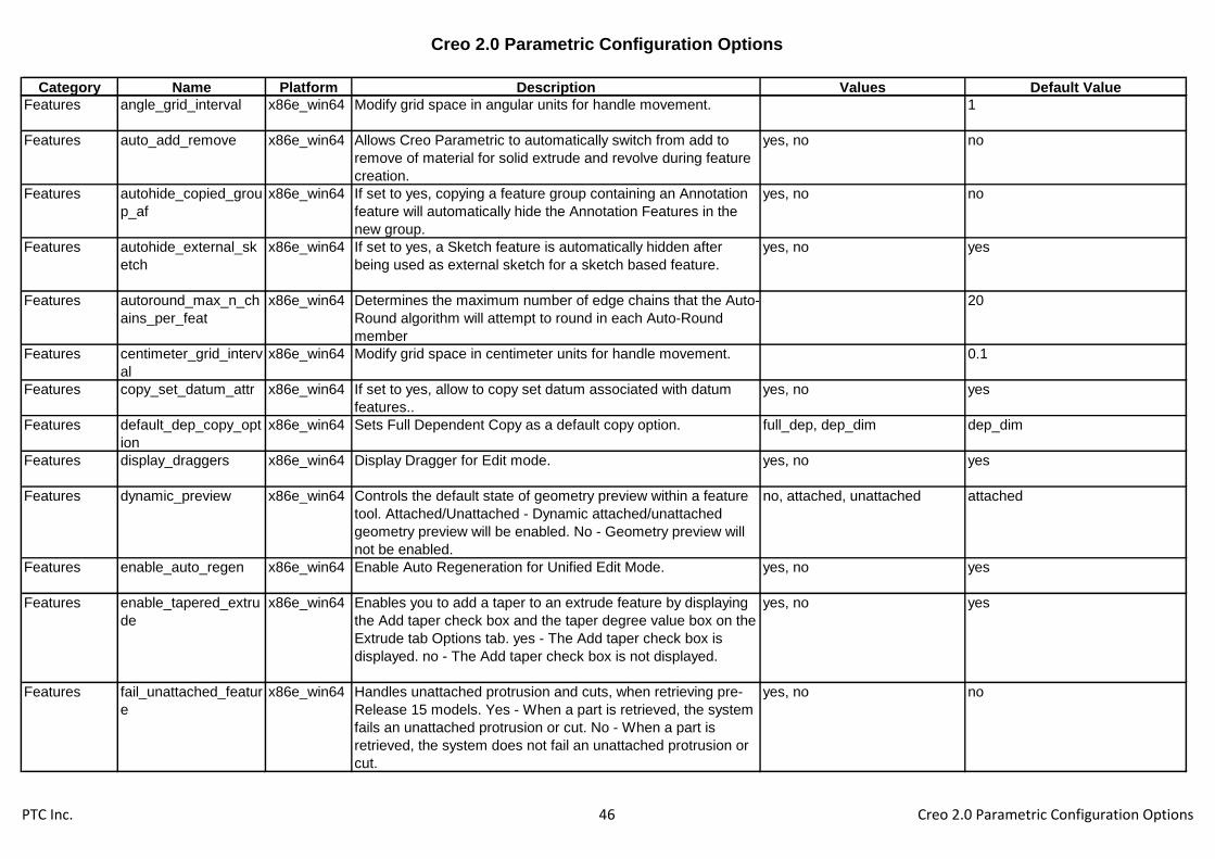
Creo 2.0 Parametric Configuration Options
Category Name Platform Description Values Default Value
Features angle_grid_interval x86e_win64 Modify grid space in angular units for handle movement. 1
Features auto_add_remove x86e_win64 Allows Creo Parametric to automatically switch from add to
remove of material for solid extrude and revolve during feature
creation.
yes, no no
Features autohide_copied_grou
p_af
x86e_win64 If set to yes, copying a feature group containing an Annotation
feature will automatically hide the Annotation Features in the
new group.
yes, no no
Features autohide_external_sk
etch
x86e_win64 If set to yes, a Sketch feature is automatically hidden after
being used as external sketch for a sketch based feature.
yes, no yes
Features autoround_max_n_ch
ains_per_feat
x86e_win64 Determines the maximum number of edge chains that the Auto-
Round algorithm will attempt to round in each Auto-Round
member
20
Features centimeter_grid_interv
al
x86e_win64 Modify grid space in centimeter units for handle movement. 0.1
Features copy_set_datum_attr x86e_win64 If set to yes, allow to copy set datum associated with datum
features..
yes, no yes
Features default_dep_copy_opt
ion
x86e_win64 Sets Full Dependent Copy as a default copy option. full_dep, dep_dim dep_dim
Features display_draggers x86e_win64 Display Dragger for Edit mode. yes, no yes
Features dynamic_preview x86e_win64 Controls the default state of geometry preview within a feature
tool. Attached/Unattached - Dynamic attached/unattached
geometry preview will be enabled. No - Geometry preview will
not be enabled.
no, attached, unattached attached
Features enable_auto_regen x86e_win64 Enable Auto Regeneration for Unified Edit Mode. yes, no yes
Features enable_tapered_extru
de
x86e_win64 Enables you to add a taper to an extrude feature by displaying
the Add taper check box and the taper degree value box on the
Extrude tab Options tab. yes - The Add taper check box is
displayed. no - The Add taper check box is not displayed.
yes, no yes
Features fail_unattached_featur
e
x86e_win64 Handles unattached protrusion and cuts, when retrieving pre-
Release 15 models. Yes - When a part is retrieved, the system
fails an unattached protrusion or cut. No - When a part is
retrieved, the system does not fail an unattached protrusion or
cut.
yes, no no
PTC Inc. 46 Creo 2.0 Parametric Configuration Options

Creo 2.0 Parametric Configuration Options
Category Name Platform Description Values Default Value
Features feature_create_auto_
begin
x86e_win64 In feature creation, determines whether or not the Define
button is automatically activated when you open the dialog box.
Yes - Button is activated automatically. No - You select the
button.
yes, no no
Features feature_create_auto_
ok
x86e_win64 In feature creation, determines whether or not the system
activates the dialog box OK button automatically when the last
required element is defined. Yes - Button is activated
automatically. No - You select the button.
yes, no no
Features feature_type_default x86e_win64 It sets the solid or surface default type for feature creation. The
Advanced option sets the default type for Extrude and Revolve
to solid, and all others to Surface.
solid, advanced, surface solid
Features foot_grid_interval x86e_win64 Modify grid space in foot units for handle movement. 0.083333
Features hole_diameter_overri
de
x86e_win64 No- Uses hole-table-driven standard hole diameter value. Yes -
Allows specifying the drilled hole value instead of the standard
value.
yes, no no
Features hole_file_resolution x86e_win64 Specify Hole tool to use external hole parameter (.hol) files. replace_with_external,
use_internal
replace_with_external
Features hole_parameter_file_
path
x86e_win64 Specifies the directory path for a standard screw-size
parameters (.hol) file to be loaded from disk. Use the full path
name to avoid problems.
Features inch_grid_interval x86e_win64 Modify grid space in inch units for handle movement. 0.03125
Features keep_info_datums x86e_win64 Sets the initial state of how the system treats datums and
features created at run time.
yes, no yes
Features max_regen_time_atta
ch_preview
x86e_win64 Sets the maximum regeneration time for the dynamic attached
preview.
0.5
Features merge_type x86e_win64 Sets the default merge type surface merge operations. join, intersect intersect
Features meter_grid_interval x86e_win64 Modify grid space in meter units for handle movement. 0.001
Features millimeter_grid_interv
al
x86e_win64 Modify grid space in millimeter units for handle movement. 0.1
Features pro_group_dir x86e_win64 Sets the default directory for the user-defined feature (UDF)
library. If not specified, your current working directory is the
default. Use the full pathname to avoid problems.
PTC Inc. 47 Creo 2.0 Parametric Configuration Options

Creo 2.0 Parametric Configuration Options
Category Name Platform Description Values Default Value
Features ratio_grid_interval x86e_win64 Modify grid space in percentage units for handle movement. 0.05
Features show_geom_checks_
on_creation
x86e_win64 Yes - The SHOW ERRORS menu appears at the end of
feature creation when the feature being created has Geometry
Checks.
yes, no no
Features troubleshooter_show_
info_gcheck
x86e_win64 When set to Yes this option will add a "Show info items" filter to
the View panel in the Troubleshooter.
yes, no no
Features udf_af_name_postfix x86e_win64 If set to yes, a sequential number will be appended to the name
of annotation feature in group from Copy and UDF placement.
yes, no yes
Features user_defined_grid_int
erval
x86e_win64 Modify grid space in user defined length units for handle
movement.
0.5
File Storage &
Retrieval
analysis_crt_tmp_file_
on_regen
x86e_win64 Determines whether regeneration of analysis features
creates/updates tmp files
yes, no yes
File Storage &
Retrieval
browser_favorite x86e_win64 Specifies the directories visible in the file browser for quick
navigation. Use the full path to avoid problems.
File Storage &
Retrieval
compress_output_file
s
x86e_win64 Yes - Stores object files in a compressed format. Note:
Compressed files are usually smaller, buy may be larger, than
uncompressed files. Compressed files are slower to read and
to write to.
yes, no no
File Storage &
Retrieval
dir_cache_max x86e_win64 Specify the maximum number of directories to cache. Larger
values can speed up file access, but use more memory.
256
File Storage &
Retrieval
disable_search_path_
check
x86e_win64 Controls whether the search path is checked for name conflicts
when creating, renaming, or copying models. Name conflicts
should be avoided because different models with the same
name cannot be together in session.
yes, no no
File Storage &
Retrieval
excel_analysis_direct
ory
x86e_win64 Sets the default directory for the MS Excel files to be used for
Excel analysis calculations. Use the full pathname to avoid
problems.
File Storage &
Retrieval
excel_family_table_ke
ep_file
x86e_win64 Yes - in case of editing family table with excel, if saved excel
file exist , will always update it.
yes, no no
File Storage &
Retrieval
exec_prog_on_assem
_retr
x86e_win64 Execute pro/program for models during assembly retrieval. yes, no no
File Storage &
Retrieval
external_analysis_dire
ctory
x86e_win64 Sets the default directory for the files to be used by External
Analysis calculations. Use the full pathname to avoid
problems.
PTC Inc. 48 Creo 2.0 Parametric Configuration Options

Creo 2.0 Parametric Configuration Options
Category Name Platform Description Values Default Value
File Storage &
Retrieval
file_open_default_fold
er
x86e_win64 Sets default dir for File>Open. Working_directory - Search
working directory. In_session - Search objects in session.
Pro_library - Use only if Pro/LIBRARY is installed. Workspace -
Use only with Pro/INTRALINK. Commonspace - Use only with
Pro/INTRALINK.
default, working_directory,
in_session, pro_library,
my_documents, desktop
File Storage &
Retrieval
file_open_default_vie
w
x86e_win64 Specify the initial Views setting as List or Details in the File
dialog boxes.
list, details list
File Storage &
Retrieval
file_open_preview_de
fault
x86e_win64 Controls whether the preview area is expanded by default
when the file open dialog or local file browser is displayed.
expanded, collapsed collapsed
File Storage &
Retrieval
file_open_preview_del
ay
x86e_win64 The delay before a file selection is previewed, in tenths of a
second.
File Storage &
Retrieval
force_new_file_option
s_dialog
x86e_win64 Force the use of the New File Options dialog. yes, no no
File Storage &
Retrieval
generate_viewable_o
n_save
x86e_win64 Controls whether updated Creo View .edz files are
automatically exported every time a model is saved.
yes, no no
File Storage &
Retrieval
geometry_analysis_co
lor_scheme
x86e_win64 Specifies the location of the geometry analysis color scheme
file.
File Storage &
Retrieval
instance_search_exh
austive
x86e_win64 Specifies extent of instance search. Yes - Include file type
when entering instance name in File>Open: type in input panel
(e.g. inst_name.prt) or select in drop-down list. If no .idx files
are found, only working dir is searched; each generic is not.
yes, no no
File Storage &
Retrieval
lang_propagate x86e_win64 Specifies language storage options. The option provides
flexibility for objects that use a different language than the
current
yes, no yes
File Storage &
Retrieval
mathcad_analysis_dir
ectory
x86e_win64 Sets the default directory for the Mathcad files to be used for
Mathcad analysis calculations. Use the full pathname to avoid
problems.
File Storage &
Retrieval
menu_show_instance
s
x86e_win64 Determines whether instance names listed in instance index
files appear in file lists.
yes, no yes
File Storage &
Retrieval
mfg_start_model_dir x86e_win64 Provides the complete path to the directory containing mfg start
assemblies.
File Storage &
Retrieval
model_rename_templ
ate
x86e_win64 Sets the default renaming convention for copied assemblies.
The default new name is the old name appended with an
underscore (_). Adding a template such as [*a1*=*b1*]
changes every occurrence of a1 to b1 (e.g.
TOP_A1_BRACKET copies to TOP_B1_BRACKET).
PTC Inc. 49 Creo 2.0 Parametric Configuration Options
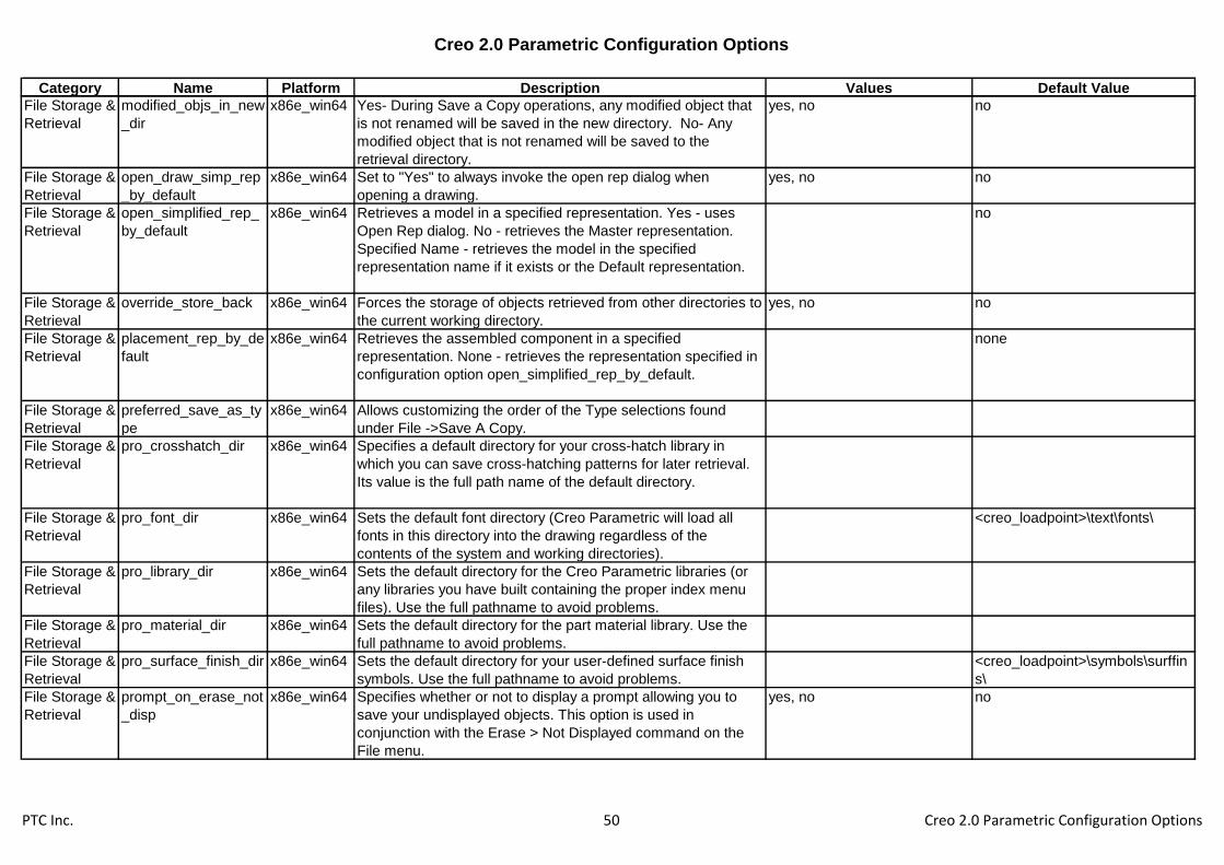
Creo 2.0 Parametric Configuration Options
Category Name Platform Description Values Default Value
File Storage &
Retrieval
modified_objs_in_new
_dir
x86e_win64 Yes- During Save a Copy operations, any modified object that
is not renamed will be saved in the new directory. No- Any
modified object that is not renamed will be saved to the
retrieval directory.
yes, no no
File Storage &
Retrieval
open_draw_simp_rep
_by_default
x86e_win64 Set to "Yes" to always invoke the open rep dialog when
opening a drawing.
yes, no no
File Storage &
Retrieval
open_simplified_rep_
by_default
x86e_win64 Retrieves a model in a specified representation. Yes - uses
Open Rep dialog. No - retrieves the Master representation.
Specified Name - retrieves the model in the specified
representation name if it exists or the Default representation.
no
File Storage &
Retrieval
override_store_back x86e_win64 Forces the storage of objects retrieved from other directories to
the current working directory.
yes, no no
File Storage &
Retrieval
placement_rep_by_de
fault
x86e_win64 Retrieves the assembled component in a specified
representation. None - retrieves the representation specified in
configuration option open_simplified_rep_by_default.
none
File Storage &
Retrieval
preferred_save_as_ty
pe
x86e_win64 Allows customizing the order of the Type selections found
under File ->Save A Copy.
File Storage &
Retrieval
pro_crosshatch_dir x86e_win64 Specifies a default directory for your cross-hatch library in
which you can save cross-hatching patterns for later retrieval.
Its value is the full path name of the default directory.
File Storage &
Retrieval
pro_font_dir x86e_win64 Sets the default font directory (Creo Parametric will load all
fonts in this directory into the drawing regardless of the
contents of the system and working directories).
<creo_loadpoint>\text\fonts\
File Storage &
Retrieval
pro_library_dir x86e_win64 Sets the default directory for the Creo Parametric libraries (or
any libraries you have built containing the proper index menu
files). Use the full pathname to avoid problems.
File Storage &
Retrieval
pro_material_dir x86e_win64 Sets the default directory for the part material library. Use the
full pathname to avoid problems.
File Storage &
Retrieval
pro_surface_finish_dir x86e_win64 Sets the default directory for your user-defined surface finish
symbols. Use the full pathname to avoid problems.
<creo_loadpoint>\symbols\surffin
s\
File Storage &
Retrieval
prompt_on_erase_not
_disp
x86e_win64 Specifies whether or not to display a prompt allowing you to
save your undisplayed objects. This option is used in
conjunction with the Erase > Not Displayed command on the
File menu.
yes, no no
PTC Inc. 50 Creo 2.0 Parametric Configuration Options

Creo 2.0 Parametric Configuration Options
Category Name Platform Description Values Default Value
File Storage &
Retrieval
propagate_change_to
_parents
x86e_win64 When saving objects with option save_objects set to Changed
or Changed_and_specified, Creo Parametric verifies which
models are. Yes - Any model that is a parent of a changed
model is considered to be a changed model when determining
what to save.
yes, no no
File Storage &
Retrieval
read_famtab_file_on_
retrieve
x86e_win64 No - Ignores filename.ptd. Yes - Creates and saves
filename.ptd and uses that file when retrieving the generic.
yes, no no
File Storage &
Retrieval
regen_simp_retrieve x86e_win64 Regenerate the assembly when retrieving an assembly
simplified representation. Yes - Regenerates the assembly on
retreival. No - The assembly is not regenerated on retrieval.
yes, no no
File Storage &
Retrieval
rename_drawings_wit
h_object
x86e_win64 Controls whether the system copies associated drawings
automatically with parts and assemblies.
none, both, part, assem none
File Storage &
Retrieval
retain_display_memor
y
x86e_win64 Determines if the display of an object currently on the screen is
kept in memory when you quit the window. Doing so (yes)
makes the retrieval of objects in memory faster.
yes, no yes
File Storage &
Retrieval
retrieve_data_sharing
_ref_parts
x86e_win64 Automatic reference parts retrieval for dependent data sharing
features.
yes, no, ignore_missing no
File Storage &
Retrieval
save_clipped_view x86e_win64 Yes - clipping status is saved with model. No - clipping status is
not saved.
yes, no no
File Storage &
Retrieval
save_dialog_for_existi
ng_models
x86e_win64 Controls whether the Save dialog is shown for models whose
storage location is already known.
yes, no yes
File Storage &
Retrieval
save_instance_accele
rator
x86e_win64 With family tables of solid parts, determines saving instance
accelerators. None - Accelerator files not used. Explicit - Save
when instance is explicitly saved. Saved objects - Save when
objects were modified. Always - Always save.
none, explicit, always,
saved_objects
saved_objects
File Storage &
Retrieval
save_model_display x86e_win64 Sets amount of graphical data stored. Wireframe - Wireframe
data. Shading_high - Most detail (shaded). Shading_low -
Least detail (shaded). Shading_lod - Detail determined by View
Performance dialog (shaded).
wireframe, shading_low,
shading_high, shading_lod
shading_lod
File Storage &
Retrieval
save_object_in_curre
nt
x86e_win64 Use with the override_store_back option. Yes - Objects
retrieved from a directory where you do not have write
permission will be stored in the current directory. No - These
objects are not saved at all.
yes, no no
PTC Inc. 51 Creo 2.0 Parametric Configuration Options
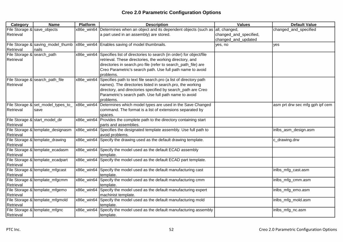
Creo 2.0 Parametric Configuration Options
Category Name Platform Description Values Default Value
File Storage &
Retrieval
save_objects x86e_win64 Determines when an object and its dependent objects (such as
a part used in an assembly) are stored.
all, changed,
changed_and_specified,
changed_and_updated
changed_and_specified
File Storage &
Retrieval
saving_model_thumb
nails
x86e_win64 Enables saving of model thumbnails. yes, no yes
File Storage &
Retrieval
search_path x86e_win64 Specifies list of directories to search (in order) for object/file
retrieval. These directories, the working directory, and
directories in search.pro file (refer to search_path_file) are
Creo Parametric's search path. Use full path name to avoid
problems.
File Storage &
Retrieval
search_path_file x86e_win64 Specifies path to text file search.pro (a list of directory path
names). The directories listed in search.pro, the working
directory, and directories specified by search_path are Creo
Parametric's search path. Use full path name to avoid
problems.
File Storage &
Retrieval
set_model_types_to_
save
x86e_win64 Determines which model types are used in the Save Changed
command. The format is a list of extensions separated by
spaces.
asm prt drw sec mfg gph ipf cem
File Storage &
Retrieval
start_model_dir x86e_win64 Provides the complete path to the directory containing start
parts and assemblies.
File Storage &
Retrieval
template_designasm x86e_win64 Specifies the designated template assembly. Use full path to
avoid problems.
inlbs_asm_design.asm
File Storage &
Retrieval
template_drawing x86e_win64 Specify the drawing used as the default drawing template. c_drawing.drw
File Storage &
Retrieval
template_ecadasm x86e_win64 Specify the model used as the default ECAD assembly
template.
File Storage &
Retrieval
template_ecadpart x86e_win64 Specify the model used as the default ECAD part template.
File Storage &
Retrieval
template_mfgcast x86e_win64 Specify the model used as the default manufacturing cast
template.
inlbs_mfg_cast.asm
File Storage &
Retrieval
template_mfgcmm x86e_win64 Specify the model used as the default manufacturing cmm
template.
inlbs_mfg_cmm.asm
File Storage &
Retrieval
template_mfgemo x86e_win64 Specify the model used as the default manufacturing expert
machinist template.
inlbs_mfg_emo.asm
File Storage &
Retrieval
template_mfgmold x86e_win64 Specify the model used as the default manufacturing mold
template.
inlbs_mfg_mold.asm
File Storage &
Retrieval
template_mfgnc x86e_win64 Specify the model used as the default manufacturing assembly
template.
inlbs_mfg_nc.asm
PTC Inc. 52 Creo 2.0 Parametric Configuration Options

Creo 2.0 Parametric Configuration Options
Category Name Platform Description Values Default Value
File Storage &
Retrieval
template_module x86e_win64 Specifies the default module template file. Use full pathname
to avoid problems.
inlbs_asm_module.asm
File Storage &
Retrieval
template_mold_layout x86e_win64 Specify the mold layout assembly used as a default template. inlbs_mold_lay.asm
File Storage &
Retrieval
template_sheetmetalp
art
x86e_win64 Specify the model used as the default sheetmetal part
template.
inlbs_part_sheetmetal.prt
File Storage &
Retrieval
template_solidpart x86e_win64 Specify the model used as the default part template. inlbs_part_solid.prt
File Storage &
Retrieval
update_accelerator_in
_verify
x86e_win64 No* - Does not update existing accelerators upon family table
verification for changes. Yes - Update existingaccelerators
upon family table verification for changes
yes, no no
File Storage &
Retrieval
use_outdated_accel_i
n_geom_rep
x86e_win64 This option controls the usage of outdated accelerator files
during retrieval of instances in geometry representation. Yes -
Provides the fastest retrieval. No - Ensures accurate Retrieval.
yes, no no
File Storage &
Retrieval
use_temp_dir_for_inst x86e_win64 Explicitly makes Creo Parametric use the Temp directory for
regenerating instances of models.
yes, no no
File Storage &
Retrieval
verify_on_save_by_d
efault
x86e_win64 Yes - "Verify Now" action will be selected in the conflict dialog
by default when an unverified family table instance is to be
saved in PDM workspace. No - "Verify Now" action will not be
selected by default. The user may explicitly specify the "Verify
Now" action in the conflict dialog.
yes, no no
Layers add_lower_level_com
ps_to_layer
x86e_win64 Setting this option to yes will check off the Favor Current Layer
option, which allows lower level components to be added to top
level layers.
yes, no no
Layers blank_layer x86e_win64 Blanks specified layers when you begin a Creo Parametric
session. The value is the layer ID.
Layers create_numbered_lay
ers
x86e_win64 Yes - Creates default layers named 1 through 32. yes, no no
PTC Inc. 53 Creo 2.0 Parametric Configuration Options

Creo 2.0 Parametric Configuration Options
Category Name Platform Description Values Default Value
Layers def_layer x86e_win64 Specifies default layer names for different types of items. The
first value string is the layer type. The second value string is the
layer name.
layer_assem_member,
layer_assy_cut_feat,
layer_axis, layer_chamfer_feat,
layer_comp_design_model,
layer_comp_fixture,
layer_comp_workpiece,
layer_copy_geom_feat,
layer_corn_chamf_feat,
layer_cosm_round_feat,
layer_cosm_sketch,
layer_csys, layer_curve,
layer_curve_ent,
layer_cut_feat, layer_datum,
layer_datum_plane,
layer_datum_point,
layer_detail_item,
layer_dgm_conn_comp,
layer_dgm_highway,
layer_dgm_rail,
PTC Inc. 54 Creo 2.0 Parametric Configuration Options

Creo 2.0 Parametric Configuration Options
Category Name Platform Description Values Default Value
layer_dgm_wire, layer_dim,
layer_draft_constr,
layer_draft_dim,
layer_draft_dtm,
layer_draft_entity,
layer_draft_feat,
layer_draft_geom,
layer_draft_grp,
layer_draft_hidden,
layer_draft_others,
layer_draft_refdim,
layer_driven_dim,
layer_dwg_table,
layer_ext_copy_geom_feat,
layer_feature,
layer_geom_feat, layer_gtol,
layer_hole_feat,
layer_intchg_funct,
layer_intchg_simp,
layer_nogeom_feat,
layer_note,
layer_parameter_dim,
PTC Inc. 55 Creo 2.0 Parametric Configuration Options

Creo 2.0 Parametric Configuration Options
Category Name Platform Description Values Default Value
layer_part_refdim, layer_point,
layer_protrusion_feat,
layer_quilt, layer_refdim,
layer_ribbon_feat,
layer_rib_feat,
layer_round_feat, layer_sfin,
layer_shell_feat,
layer_skeleton_model,
layer_slot_feat,
layer_snap_line,
layer_solid_geom,
layer_surface, layer_symbol,
layer_thread_feat,
layer_trim_line_feat,
layer_weld_feat,
layer_all_detail_items,
layer_annotation_element,
layer_axis_ent, layer_csys_ent,
layer_set_datum_tag,
layer_3d_items,
layer_ae_driving_dim,
layer_draft_xsec,
layer_hole_thread
Layers default_layer_model x86e_win64 Name of the model which is used to drive rule-based layer
placement of new items in all models of the same type in
session.
Layers display_layer x86e_win64 This causes the specified layers to display when you begin a
Creo Parametric session. The variable "value" is the layer Id.
Layers floating_layer_tree x86e_win64 Set to yes if user wants to see a layer tree dialog separated
from navigator.
yes, no no
Layers highlight_layer_items x86e_win64 Yes - Items selected in the layer tree are highlighted in the
geometry area.
yes, no yes
Layers layer_item_highlight_li
mit
x86e_win64 Set the upper limit of items in a layer for highlighting. If items in
a layer exceeds this number, highlighting will not occur.
500
PTC Inc. 56 Creo 2.0 Parametric Configuration Options
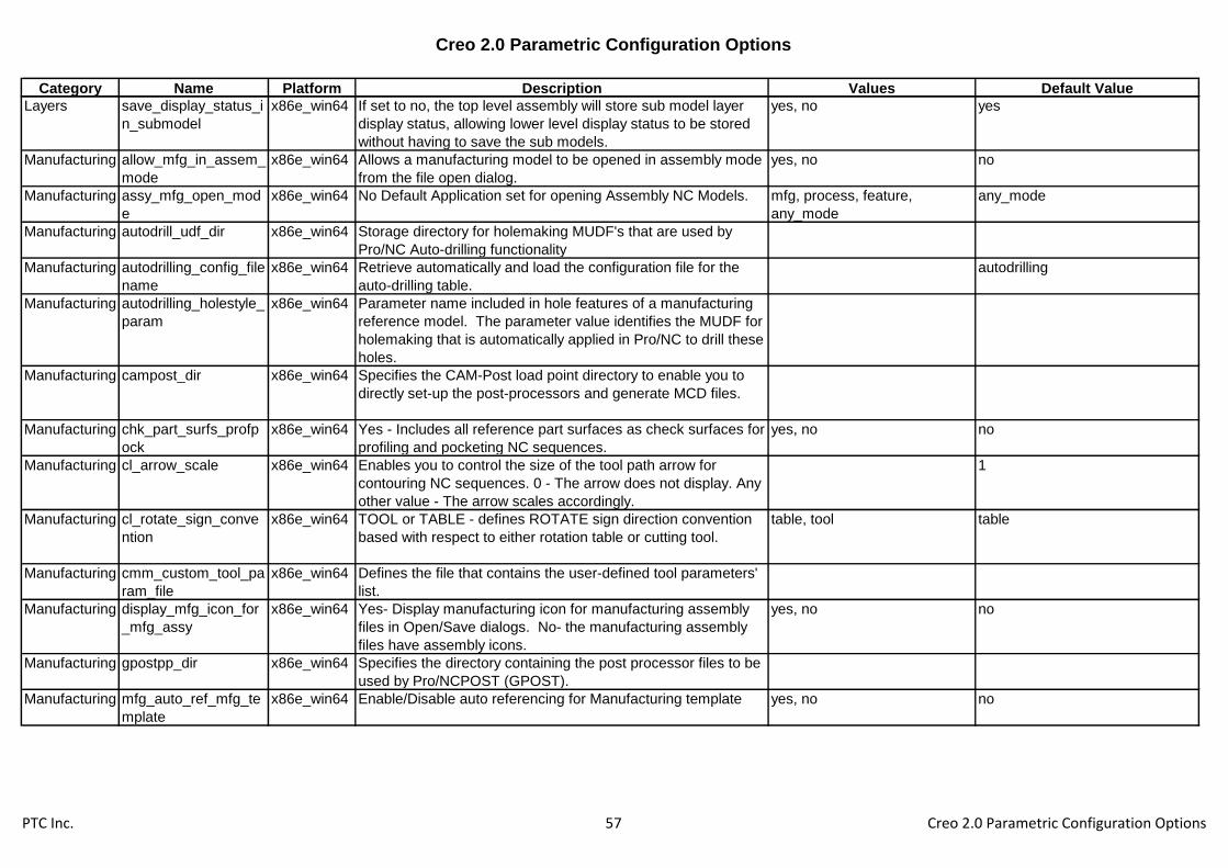
Creo 2.0 Parametric Configuration Options
Category Name Platform Description Values Default Value
Layers save_display_status_i
n_submodel
x86e_win64 If set to no, the top level assembly will store sub model layer
display status, allowing lower level display status to be stored
without having to save the sub models.
yes, no yes
Manufacturing allow_mfg_in_assem_
mode
x86e_win64 Allows a manufacturing model to be opened in assembly mode
from the file open dialog.
yes, no no
Manufacturing assy_mfg_open_mod
e
x86e_win64 No Default Application set for opening Assembly NC Models. mfg, process, feature,
any_mode
any_mode
Manufacturing autodrill_udf_dir x86e_win64 Storage directory for holemaking MUDF's that are used by
Pro/NC Auto-drilling functionality
Manufacturing autodrilling_config_file
name
x86e_win64 Retrieve automatically and load the configuration file for the
auto-drilling table.
autodrilling
Manufacturing autodrilling_holestyle_
param
x86e_win64 Parameter name included in hole features of a manufacturing
reference model. The parameter value identifies the MUDF for
holemaking that is automatically applied in Pro/NC to drill these
holes.
Manufacturing campost_dir x86e_win64 Specifies the CAM-Post load point directory to enable you to
directly set-up the post-processors and generate MCD files.
Manufacturing chk_part_surfs_profp
ock
x86e_win64 Yes - Includes all reference part surfaces as check surfaces for
profiling and pocketing NC sequences.
yes, no no
Manufacturing cl_arrow_scale x86e_win64 Enables you to control the size of the tool path arrow for
contouring NC sequences. 0 - The arrow does not display. Any
other value - The arrow scales accordingly.
1
Manufacturing cl_rotate_sign_conve
ntion
x86e_win64 TOOL or TABLE - defines ROTATE sign direction convention
based with respect to either rotation table or cutting tool.
table, tool table
Manufacturing cmm_custom_tool_pa
ram_file
x86e_win64 Defines the file that contains the user-defined tool parameters'
list.
Manufacturing display_mfg_icon_for
_mfg_assy
x86e_win64 Yes- Display manufacturing icon for manufacturing assembly
files in Open/Save dialogs. No- the manufacturing assembly
files have assembly icons.
yes, no no
Manufacturing gpostpp_dir x86e_win64 Specifies the directory containing the post processor files to be
used by Pro/NCPOST (GPOST).
Manufacturing mfg_auto_ref_mfg_te
mplate
x86e_win64 Enable/Disable auto referencing for Manufacturing template yes, no no
PTC Inc. 57 Creo 2.0 Parametric Configuration Options

Creo 2.0 Parametric Configuration Options
Category Name Platform Description Values Default Value
Manufacturing mfg_auto_ref_prt_as_
chk_srf
x86e_win64 Yes - In 3, 4, and 5 axis contour and conventional mill
sequences, the entire reference part is selected as check
surfaces by default when computing the NC sequence toolpath
for those sequences. No - You select the check surfaces.
yes, no yes
Manufacturing mfg_auto_retract_cle
ar_dist
x86e_win64 Specifies distance between automatically created retract plane
and step coordinate system. Will be applied to the new steps
created in process manager if operation retract cannot be
used.
0
Manufacturing mfg_custom_tool_par
am_file
x86e_win64 Defines the file that contains the user-defined tool parameters'
list.
Manufacturing mfg_customize_dialo
g
x86e_win64 Yes - Uses the new customize dialog box for customizing NC
sequences. No - Uses the Release 19.0 menus.
yes, no yes
Manufacturing mfg_cutline_save_me
sh
x86e_win64 Yes - Save / Retrieve Mesh for subsequent cutline
recalculations, No - New Mesh will be computed for each
cutline recalculations.
yes, no yes
Manufacturing mfg_ijk_num_digits x86e_win64 Sets the number of digits for i, j, k data points in a CL data file. 10
Manufacturing mfg_info_location x86e_win64 top left /bottom right -Position of the mfg. Info dialog box. top_left, bottom_right top_left
Manufacturing mfg_modal_comman
d_file
x86e_win64 Enables you to make some of the APTn index topics modal,
which means that you repeatedly get a list of major keywords
corresponding to this topic upon completing a command line.
Manufacturing mfg_param_auto_cop
y_from_tool
x86e_win64 Do not copy any parameter of the tool to the sequence
parameter tree.
all, none, misc, cutting none
Manufacturing mfg_process_print_di
r
x86e_win64 Specifies the directory where Mfg Process html page get
stored. Use the full pathname to avoid problems.
Manufacturing mfg_process_sync_b
y_default
x86e_win64 Specifies whether all steps created in the Process Manager get
automatically synchronized with features in the Pro/NC
assembly. You can change steps later in the dialog box open
during the session.
yes, no yes
Manufacturing mfg_process_table_s
etup_dir
x86e_win64 Specifies the directory where Mfg Process Table settings get
stored. Use the full pathname to avoid problems.
Manufacturing mfg_process_templat
e_dir
x86e_win64 Specifies the directory where Mfg Process Templates get
stored. Use the full pathname to avoid problems.
Manufacturing mfg_setup_dir x86e_win64 Specifies the directory which contains all manufacturing related
setup files for the current session.
PTC Inc. 58 Creo 2.0 Parametric Configuration Options

Creo 2.0 Parametric Configuration Options
Category Name Platform Description Values Default Value
Manufacturing mfg_stock_display_sh
ow_default
x86e_win64 yes, no no
Manufacturing mfg_template_dir x86e_win64 Specifies the storage directory for NC templates. Specify full
path to avoid problems. NC templates are used in Expert
Machinist. Templates store the recipe for a toolpath as the
method of tool retrieval.
Manufacturing mfg_tool_dialog_setu
p_file
x86e_win64 Specifies the XML based file to setup Tool Dialog.
Manufacturing mfg_udf_info_setup_fi
le
x86e_win64 Specify name and path of the file containing udf and mfg
criteria values .
Manufacturing mfg_workpiece_trans
parency
x86e_win64 Controls the workpiece transparency in shaded model display.
You can change the value in the range between 0.1 and 1. The
bigger the value, the more transparent the workpiece. The
default value is 0.5.
0.67
Manufacturing mfg_xyz_num_digits x86e_win64 Sets the number of digits for x, y, z data points in a CL data file. 10
Manufacturing nc_autodoc_param_di
r
x86e_win64 Location of the setup file that describes which process
parameters are included in the parameter table.
Manufacturing nc_autodoc_report_di
r
x86e_win64 Location for storing the report and images generated by the
shop floor documentation tool.
Manufacturing nc_autodoc_setup_dir x86e_win64 Location for documentation setup files that describe which
process parameters are included in the parameter table.
Manufacturing nc_autodoc_template
_dir
x86e_win64 Location of the style sheet and default images used for shop
floor documentation.
Manufacturing nccheck_type x86e_win64 Vericut will be used for NC material removal simulation. vericut, nccheck vericut
Manufacturing ncl_file_extension x86e_win64 Sets the default file extension for Pro/MFG CL data files. Enter
the file extension only (without the preceding "."). For example,
apt produces filename.apt.
ncl
Manufacturing ncmdl_bar_stock_part
_path
x86e_win64 Sets path for storage and retrieval of stock instances for
creating workpiece in NC Model. Specify full path, including
part name, to avoid problems.
<creo_loadpoint>\text\ncmdl_dat
a\ncmdl_bar.prt
Manufacturing ncmdl_billet_stock_pa
rt_path
x86e_win64 Sets path for storage and retrieval of stock instances for
creating workpiece in NC Model. Specify full path, including
part name, to avoid problems.
<creo_loadpoint>\text\ncmdl_dat
a\ncmdl_billet.prt
Manufacturing ncpost_type x86e_win64 Set to GPOST to access the default post processor supplied
with Pro/NCPOST.
gpost, ncpost
PTC Inc. 59 Creo 2.0 Parametric Configuration Options

Creo 2.0 Parametric Configuration Options
Category Name Platform Description Values Default Value
Manufacturing ncseq_outbound_curv
e
x86e_win64 Yes - Create out bound curve. yes
Manufacturing new_turn_scan_type x86e_win64 Allows to use New turn scan types for Turning NC sequences. yes, no yes
Manufacturing pro_mdb_dir x86e_win64 Sets the default directory for the Machinability Database (MDB)
files. Use the full pathname to avoid problems.
Manufacturing pro_mf_cl_dir x86e_win64 Sets the default directory for the manufacturing CL data
files.Use the full pathname to avoid problems.
Manufacturing pro_mf_clamp_dir x86e_win64 Specifies the directory where the manufacturing clamps can be
found.
Manufacturing pro_mf_param_dir x86e_win64 Sets the default directory for the manufacturing parameter files.
Use the full pathname to avoid problems.
Manufacturing pro_mf_tape_dir x86e_win64 Sets the default directory for the manufacturing TAPE data
files.Use the full pathname to avoid problems.
Manufacturing pro_mf_tprm_dir x86e_win64 Sets the default directory for the manufacturing tool files. Use
the full pathname to avoid problems.
Manufacturing pro_mf_workcell_dir x86e_win64 Sets the default directory for the manufacturing workcell files.
Use the full pathname to avoid problems.
Manufacturing pro_mfg_cmdsyn_dir x86e_win64 Sets the default directory for the syntax menu files in Pro/MFG.
Use the full pathname to avoid problems.
Manufacturing profile_output_utils x86e_win64 Affects CL-Data output for profile milling sequences. Yes -
Sequence parameter output_point is available with options: tip -
Toolpath is output with respect to the tool center; on_profile -
Toolpath is output with respect to the profile of the tool.
yes, no no
Manufacturing proncpost_dbf x86e_win64 Enter directory path to NCPost database file.
Manufacturing prorembatch_queue_
manager
x86e_win64 Enables toolpath computation on a separate host machine.
Required values are Processor name, Remote machine's
hostname, Type of transport (always 0), RPC processor
number (same as that of remote processor), Version of queue
manager.
Manufacturing ptncpost_dbf x86e_win64 Enter directory path to NCPost database file.
Manufacturing reverse_spiral_finish_
type
x86e_win64 If the option value is 1, the tool path is obtained from standard
one by reversing it; if the option value is 2, the tool path starts
from an inner circle.
PTC Inc. 60 Creo 2.0 Parametric Configuration Options

Creo 2.0 Parametric Configuration Options
Category Name Platform Description Values Default Value
Manufacturing shade_mfg_ref_mode
ls
x86e_win64 No - Does not process reference parts when generating the
shaded image (to save time). Yes - Shades reference parts
when generating shaded images.
yes, no yes
Manufacturing store_tool_path_file x86e_win64 Specifies how tool path information is computed. Yes - Tool
path information stored in file filename.tph (filename is
manufacturing model name). No - Tool path is computed each
time manufacturing model is retrieved or parameters are
changed.
yes, no yes
Manufacturing tool_path_preview_de
fault
x86e_win64 Sets tool path preview default mode to OFF. off, on, auto auto
Manufacturing turn_avoid_holder_int
erference
x86e_win64 Yes - Tool holder interference will be ignored during Turning
toolpath calculation.
yes, no no
Manufacturing wcell_fixt_info_setup_
file
x86e_win64 Specify name and path of the file containing workcell and
fixture name info.
Manufacturing workpiece_instances x86e_win64 Instances are created in Workpiece for each steps. steps, operations_and_steps
Mechanica custom_rainbow x86e_win64 Used to specify fringe colors in Pro/FEM-POST results. Specify
blue, black, cyan, magenta, green, yellow, red, and white. Enter
colors as a dash-delimited string (lowest to highest value). The
default is blue-cyan-green-yellow-red-magenta-white.
Mechanica sim_hyperelastic_mat
erial_fit
x86e_win64 Sets the default method for calculating coefficients for
hyperelastic materials. If set to "normalized", normalized
stresses will be used. If set to "non-normalized", non-
normalized stresses will be used.)
normalized, non-normalized normalized
Mechanism mdo_cl_executable x86e_win64 Path for Custom Load executable.
Mechanism mdo_integration_met
hod
x86e_win64 Select integration method for dynamic analyses. explicit, implicit, auto auto
Mechanism mdo_spring_wire_radi
us
x86e_win64 Spring wire radius for dynamics spring icons. 0.15
Mechanism mdx_belt_icon_width x86e_win64 Width of belt transmission icons. 5
Mechanism motion_envlp_alert x86e_win64 Displays the Motion Envelope alert the first time the quality
level is increased.
yes, no yes
Mechanism move_mechanism_in
_nongeom_reps
x86e_win64 Allow mechanism operations in non geometrical
representations.
yes, no, exclude_to_move yes
PTC Inc. 61 Creo 2.0 Parametric Configuration Options

Creo 2.0 Parametric Configuration Options
Category Name Platform Description Values Default Value
Miscellaneous allow_ply_cross_secti
on
x86e_win64 Yes - Enables Pro/COMPOSITE to create a cross-section of
composite plys.
yes, no yes
Miscellaneous conf_mouse_anim x86e_win64 Display the presenter's mouse motions when observing a
shared Creo Parametric session.
yes, no no
Miscellaneous mapkey x86e_win64 Stores a keyboard macro. Use File > Options > Environment >
Mapkey Settings to create, edit and delete mapkeys.
Miscellaneous mapkeys_execution x86e_win64 Mapkeys execution behavior. No Feedback - The mapkey is
executed with no feedback, Execute with Feedback - A
warning message is given upon failure during execution, Stop
at failure - The execution stops at failure and a feedback
message is provided.
no_feedback,
execute_with_feedback,
stop_at_failure
no_feedback
Miscellaneous relation_text_trail_out
put
x86e_win64 No - Disable trail output from Text layout in Relation Parameter
UI if it hasn't been changed.
yes, no yes
Miscellaneous relation_tool_mapkey
_behavior
x86e_win64 Will control how mapkeys will be executed in relation tool /
dialog. Incremental will add/remove text incrementally to the
current set. Full_output will record the original set state and
replace the current one with it. Note: this config is dependent
on relation_text_trail_output.
increment, full_output increment
Miscellaneous show_cav_fit_loc_sys x86e_win64 Allows the printing of the transformation matrix of a Pro/Verify
Fit into a file.
yes, no no
Model Display allow_solid_perspecti
ve_hlr
x86e_win64 Yes - Allows a solid to be displayed with hidden lines while in
perspective.
yes, no yes
Model Display animate_component_
placement
x86e_win64 Animate the transition between component states in
placement.
yes, no yes
Model Display animate_explode_stat
es
x86e_win64 Animate the transition between explode states and mold
opening steps.
yes, no yes
Model Display blended_transparency x86e_win64 Yes - Transparent colors will appear using alpha blending (if
supported) when the model is shaded.
yes, no, independent yes
Model Display capped_clip x86e_win64 Yes - Displays the model as a solid when shaded and clipped.
No - Displays the model as surfaces when shaded and clipped.
yes, no yes
Model Display clip_always x86e_win64 Yes - Display clipping after Visibilities dialog box is closed. yes, no yes
Model Display datum_point_symbol x86e_win64 Specifies the shape of datum point symbols displayed in Part
or Assembly mode.
dot cross
Model Display default_ramp_size x86e_win64 Specifies a number of shades of gray to show shading of non-
colored objects.
PTC Inc. 62 Creo 2.0 Parametric Configuration Options

Creo 2.0 Parametric Configuration Options
Category Name Platform Description Values Default Value
Model Display disp_comp_name_in_
symb_rep
x86e_win64 Displays the names of components in symbolic
representations.
yes, no yes
Model Display display x86e_win64 Wireframe - All solid edges in white. Hiddenvis - Hidden lines in
grey. Hiddeninvis - Hidden lines removed. Shade - Display
shaded surfaces. Settings are reflected in printing and some
export modes.
wireframe, hiddenvis,
hiddeninvis, shade,
shadewithreflect,
shadewithedges
shade
Model Display display_axes x86e_win64 Displays or hides datum axes. yes, no yes
Model Display display_axis_tags x86e_win64 Displays or hides datum axis name tags. yes, no no
Model Display display_coord_sys x86e_win64 Yes - Coordinate systems will be displayed. No - Coordinate
systems will not be displayed.
yes, no yes
Model Display display_coord_sys_ta
gs
x86e_win64 Yes - Coordinate system name tags will be displayed. No -
Coordinate system name tags will not be displayed.
yes, no yes
Model Display display_florin x86e_win64 Yes: display of the florin (international currency symbol) where
possible. No: use the euro symbol exclusively.
yes, no no
Model Display display_plane_tags x86e_win64 Yes - Datum plane name tags will be displayed. No - Datum
plane name tags will not be displayed.
yes, no no
Model Display display_planes x86e_win64 Yes - Datum planes will be displayed. No - Datum planes will
not be displayed.
yes, no yes
Model Display display_point_tags x86e_win64 Yes - Datum point tags will be displayed. No - Datum point tags
will not be displayed.
yes, no no
Model Display display_points x86e_win64 Yes - Datum points and their names will be displayed. No -
Datum points and their names will not be displayed.
yes, no yes
Model Display display_silhouette_ed
ges
x86e_win64 Sets the display of silhouette edges for wireframe display only. yes, no yes
Model Display display_z_extension_l
ines
x86e_win64 Controls the display of dimension z-extension lines. Yes - z-
extension lines will be displayed; No - z-extension lines will not
be displayed.
yes, no yes
Model Display edge_display_quality x86e_win64 Controls display quality of an edge for wireframe and hidden-
line removal. Normal - Normal quality of edge display. High -
Increases tessellation by 2. Very_high - Increases tessellation
by 3. Low - Decreases tessellation from normal, speeds up
display.
high, low, normal, very_high normal
Model Display enable_hlr_hashing x86e_win64 Enables hlr hashing yes, no no
Model Display enable_transparent_t
ext_bg
x86e_win64 Yes - Clear background before displaying text. No - Do not
clear text background.
yes, no yes
PTC Inc. 63 Creo 2.0 Parametric Configuration Options

Creo 2.0 Parametric Configuration Options
Category Name Platform Description Values Default Value
Model Display explode_animation_m
ax_time
x86e_win64 Sets the maximum amount of time for an animation between
explode states.
1
Model Display fast_highlight x86e_win64 Yes - Use simplified highlighting which redisplays more quickly
at the expense of certain details. This option may increase
memory usage slightly.
yes, no yes
Model Display fasthlr x86e_win64 Specifies whether fast hidden line removal is on/off by default. yes, no no
Model Display frames_per_sec x86e_win64 Determines whether view is animated. yes, no no
Model Display frames_per_sec_valu
e
x86e_win64 Used to set the smoothness of view animation changes. Higher
numbers provide more frames/sec, and giving you a smoother
animation. Lower numbers cause the view to change more
quickly.
3
Model Display lods_enabled x86e_win64 Determines whether or not the system uses Level of Detail in
shaded models during dynamic orientation (panning, zooming
and spinning).
yes, no no
Model Display lods_value x86e_win64 When lods_enabled is Yes, this value specifies the default
value used to display LODs. The value is a percentage of the
edge size vs the total size of the model.
50
Model Display max_animation_time x86e_win64 When the orientation, or zoom state, of the Creo Parametric
window changes, an animation sequence of a predefined
duration takes place. This option controls the maximum time
the system spends animating.
1
Model Display max_image_dimensio
n
x86e_win64 Set the upper bound dimension on images loaded into Creo
Parametric. Images larger than this limit will be rescaled to this
upper bound during loading.
4096, 1024, 2048, 8192, 16384 4096
Model Display mesh_spline_surf x86e_win64 Turns the blue mesh surface lines on or off. yes, no no
Model Display min_animation_steps x86e_win64 When the orientation, or zoom state, of the Creo Parametric
window changes, an animation sequence of predefined
duration takes place. This option controls the minimum number
of frames used in the animation sequence.
6
Model Display model_detail_options
_file
x86e_win64 Sets the path to the file which contains the default model detail
option values for new models.
<creo_loadpoint>\text\3d_inch.dtl
Model Display orientation x86e_win64 Establishes the initial standard view orientation. User_default -
System uses X-axis and Y-axis values defined by options
x_axis and y_axis.
isometric, trimetric,
user_default
trimetric
PTC Inc. 64 Creo 2.0 Parametric Configuration Options
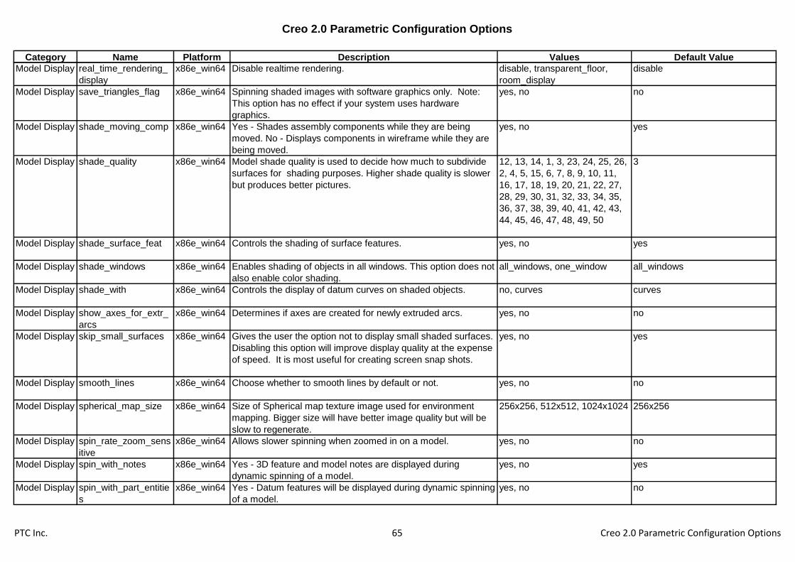
Creo 2.0 Parametric Configuration Options
Category Name Platform Description Values Default Value
Model Display real_time_rendering_
display
x86e_win64 Disable realtime rendering. disable, transparent_floor,
room_display
disable
Model Display save_triangles_flag x86e_win64 Spinning shaded images with software graphics only. Note:
This option has no effect if your system uses hardware
graphics.
yes, no no
Model Display shade_moving_comp x86e_win64 Yes - Shades assembly components while they are being
moved. No - Displays components in wireframe while they are
being moved.
yes, no yes
Model Display shade_quality x86e_win64 Model shade quality is used to decide how much to subdivide
surfaces for shading purposes. Higher shade quality is slower
but produces better pictures.
12, 13, 14, 1, 3, 23, 24, 25, 26,
2, 4, 5, 15, 6, 7, 8, 9, 10, 11,
16, 17, 18, 19, 20, 21, 22, 27,
28, 29, 30, 31, 32, 33, 34, 35,
36, 37, 38, 39, 40, 41, 42, 43,
44, 45, 46, 47, 48, 49, 50
3
Model Display shade_surface_feat x86e_win64 Controls the shading of surface features. yes, no yes
Model Display shade_windows x86e_win64 Enables shading of objects in all windows. This option does not
also enable color shading.
all_windows, one_window all_windows
Model Display shade_with x86e_win64 Controls the display of datum curves on shaded objects. no, curves curves
Model Display show_axes_for_extr_
arcs
x86e_win64 Determines if axes are created for newly extruded arcs. yes, no no
Model Display skip_small_surfaces x86e_win64 Gives the user the option not to display small shaded surfaces.
Disabling this option will improve display quality at the expense
of speed. It is most useful for creating screen snap shots.
yes, no yes
Model Display smooth_lines x86e_win64 Choose whether to smooth lines by default or not. yes, no no
Model Display spherical_map_size x86e_win64 Size of Spherical map texture image used for environment
mapping. Bigger size will have better image quality but will be
slow to regenerate.
256x256, 512x512, 1024x1024 256x256
Model Display spin_rate_zoom_sens
itive
x86e_win64 Allows slower spinning when zoomed in on a model. yes, no no
Model Display spin_with_notes x86e_win64 Yes - 3D feature and model notes are displayed during
dynamic spinning of a model.
yes, no yes
Model Display spin_with_part_entitie
s
x86e_win64 Yes - Datum features will be displayed during dynamic spinning
of a model.
yes, no no
PTC Inc. 65 Creo 2.0 Parametric Configuration Options

Creo 2.0 Parametric Configuration Options
Category Name Platform Description Values Default Value
Model Display spin_with_silhouettes x86e_win64 Yes - Silhouette lines will be displayed during dynamic spinning
of a model.
yes, no no
Model Display tan_angle_for_disp x86e_win64 For display purposes only. Sets the angle between two quilt
surfaces below which the edge will be displayed as tangent.
Enter an angle between 1.5 and 15 degrees.
0.02618
Model Display tangent_edge_display x86e_win64 Determines how edges between tangent surfaces are
displayed.
no, solid, centerline, phantom,
dimmed
solid
Model Display texture x86e_win64 Yes - Applied textures will be displayed when the model is
shaded.
yes, no yes
Model Display texture_search_path x86e_win64 Appends a directory to the search path for textures.
Model Display transparency x86e_win64 Yes - Transparent colors will appear as such when the model
is shaded.
yes, no yes
Model Display use_pre_wildfire_text
_font
x86e_win64 Yes - Use the old stroke-based PTC font as the default font. No
- Use a True Type font as the default font.
yes, no no
Model Display x_angle x86e_win64 Sets the default view orientation for models (appears in the
Orientation dialog box). The default orientation is the last
option, x_angle, y_angle, or orientation, in the configuration file.
0
Model Display y_angle x86e_win64 Sets the default view orientation for models (appears in the
Orientation dialog box). The default orientation is the last
option, x_angle, y_angle, or orientation, in the configuration file.
0
Photorender default_scene_filena
me
x86e_win64 Complete path to the scene file to be used as default scene
file.
<creo_loadpoint>\graphic-
library\scenes\/creo_default_scen
e.scn
Photorender photorender_capabilit
y_warnings
x86e_win64 Allows the user to disable warnings about PhotoLux only
capabilities.
yes, no yes
Photorender photorender_default_
height
x86e_win64 Sets the default height (in pixels) for the custom size rendered
output
450
Photorender photorender_default_
width
x86e_win64 Sets the default width (in pixels) for the custom size rendered
output
600
Photorender photorender_memory
_usage
x86e_win64 Sets the memory limit that Pro/PHOTORENDER allows for
model processing. Do not use commas in the memory value,
as Creo Parametric interprets these as decimals. The
minimum allowed value is 64 and maximum value is 5120.
256
PTC Inc. 66 Creo 2.0 Parametric Configuration Options

Creo 2.0 Parametric Configuration Options
Category Name Platform Description Values Default Value
Photorender photorender_preview_
scale
x86e_win64 Allows user defined size ratio at which Pro/PHOTORENDER
will render, using the default Render To: Full Window Preview
setting. Increasing the value creates higher quality rendering
with slower performance. Reducing the value produces reverse
results.
0.5
Photorender pro_texture_library x86e_win64 Allows the user to specify a different graphics library.
Photorender room_rotation_lock x86e_win64 Default room rotation setting at session start. studio - Lock
room rotation to studio. model - Lock room rotation to model.
studio, model studio
Photorender save_scene_with_file x86e_win64 Yes - Automatically update the model with current scene
information when saving the model; No - Scene information
embedded in model must be updated manually.
yes, no no
Photorender save_texture_with_m
odel
x86e_win64 Yes - Embed applied texture and tracesketch bitmap files into
the model file.
yes, no no
Photorender window_gamma x86e_win64 Gamma correction to apply to images created by renderer.
Default value is 1.0.
1
Piping aec_dwg_anno_attrpa
r_spec_file
x86e_win64 Specifies the aec drawing annotation attribute/parameter
specification file name.
aec_dwg_anno_attrparam_spec.
ptd
Piping aec_object_type_file x86e_win64 Specifies the aec object type file name. aec_object_type.ptd
Piping display_thick_insulatio
n
x86e_win64 Yes - Display insulation in thick mode. No - Display insulation in
centerline mode. This option can be overridden by the Thick
insulation option in the Model Display dialog box.
yes, no yes
Piping display_thick_pipes x86e_win64 Yes - Display pipes in thick mode. No - Display pipes in
centerline mode. This option can be overridden by the Thick
pipes option in the Model Display dialog box.
yes, no no
Piping isogen_attribute_map
_file
x86e_win64 Specifies the mapping between isogen parameter and attribute
name.
<creo_loadpoint>\text\piping_data
\isodata\isogen_attribute_map.pt
d
Piping isogen_endtype_map
_file
x86e_win64 Specify name of file mapping Pro/Piping endtypes with
ISOGEN endtypes
<creo_loadpoint>\text\piping_data
\isodata\isogen_endtype_map.ptd
Piping isogen_mandatory_att
r_file
x86e_win64 Specify file containing mandatory attribute filenames used by
ISOGEN.
isogen.fls
PTC Inc. 67 Creo 2.0 Parametric Configuration Options

Creo 2.0 Parametric Configuration Options
Category Name Platform Description Values Default Value
Piping isogen_nominal_size_
map_file
x86e_win64 Specify name of file mapping Pro/Piping Size with Nominal
Sizes in MM and Inches
<creo_loadpoint>\text\piping_data
\isodata\isogen_nominal_size_m
ap.ptd
Piping isogen_output_files_d
ir
x86e_win64 Specify directory to save the PCFs created by ISOGEN
interface
Piping isogen_pcf_filename_
format
x86e_win64 Specify format to create filenames of PCF files being created mnemonic,-,specification,-
,number
Piping isogen_symbol_map_
file
x86e_win64 Specify name of file for mapping Pro/Piping selection names
with ISOGEN symbol keys (SKEY)s
<creo_loadpoint>\text\piping_data
\isodata\isogen_symbol_map.ptd
Piping pipe_bend_locations_
csys_units
x86e_win64 Define which assembly units will be used for the piping bend
locations calculations. Yes - to use coordinate system
assembly units. No - to use pipeline assembly units.
yes, no no
Piping pipe_pre_22_bendinf
o_conv
x86e_win64 Convert bend report information generated prior to
Pro/ENGINEER 2000i-2 to current saved analysis format.
yes, no yes
Piping pipe_solid_centerline x86e_win64 Yes - Display Pro/PIPING centerlines. No - Do not display
Pro/PIPING centerlines.
yes, no yes
Piping pipe_solid_label_form
at
x86e_win64 Specify the pipe solid label format that will be used to
automatically generate pipeline labels.
size,-,specification,-,mnemonic,-
,number,-,insulation
Piping pipe_update_pre_20_i
nt_pts
x86e_win64 Yes - Pipelines created prior to Release 20.0 are updated with
intersection point entities. The entities are created in session
by Info>Regen Info or when you retrieve the model.
yes, no no
Piping pipeline_assembly_lib
rary_dir
x86e_win64 Sets the default pipeline assembly library directory. <creo_loadpoint>\text\piping_data
\pipelinelib\
Piping pipeline_assembly_na
me_format
x86e_win64 Sets the default pipeline assembly name format. mnemonic,-,number
Piping pipeline_label_format x86e_win64 Specify the pipeline label format that will be used to
automatically generate pipeline labels.
size,-,specification,-,mnemonic,-
,number,-,insulation
Piping pipeline_solid_start_p
art_name
x86e_win64 Sets the default pipeline solid start part name. pipeline_solid_start.prt
Piping pipeline_spool_label_f
ormat
x86e_win64 Specify the pipeline spool label format that will be used to
generate the spool labels during pipeline spool generation.
mnemonic-number-
prefix[0]spoolnum[01]s
uffix[]
PTC Inc. 68 Creo 2.0 Parametric Configuration Options
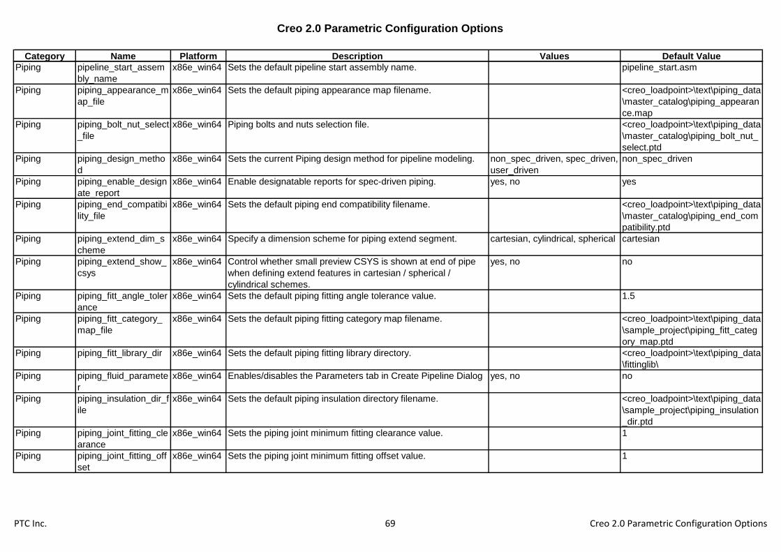
Creo 2.0 Parametric Configuration Options
Category Name Platform Description Values Default Value
Piping pipeline_start_assem
bly_name
x86e_win64 Sets the default pipeline start assembly name. pipeline_start.asm
Piping piping_appearance_m
ap_file
x86e_win64 Sets the default piping appearance map filename. <creo_loadpoint>\text\piping_data
\master_catalog\piping_appearan
ce.map
Piping piping_bolt_nut_select
_file
x86e_win64 Piping bolts and nuts selection file. <creo_loadpoint>\text\piping_data
\master_catalog\piping_bolt_nut_
select.ptd
Piping piping_design_metho
d
x86e_win64 Sets the current Piping design method for pipeline modeling. non_spec_driven, spec_driven,
user_driven
non_spec_driven
Piping piping_enable_design
ate_report
x86e_win64 Enable designatable reports for spec-driven piping. yes, no yes
Piping piping_end_compatibi
lity_file
x86e_win64 Sets the default piping end compatibility filename. <creo_loadpoint>\text\piping_data
\master_catalog\piping_end_com
patibility.ptd
Piping piping_extend_dim_s
cheme
x86e_win64 Specify a dimension scheme for piping extend segment. cartesian, cylindrical, spherical cartesian
Piping piping_extend_show_
csys
x86e_win64 Control whether small preview CSYS is shown at end of pipe
when defining extend features in cartesian / spherical /
cylindrical schemes.
yes, no no
Piping piping_fitt_angle_toler
ance
x86e_win64 Sets the default piping fitting angle tolerance value. 1.5
Piping piping_fitt_category_
map_file
x86e_win64 Sets the default piping fitting category map filename. <creo_loadpoint>\text\piping_data
\sample_project\piping_fitt_categ
ory_map.ptd
Piping piping_fitt_library_dir x86e_win64 Sets the default piping fitting library directory. <creo_loadpoint>\text\piping_data
\fittinglib\
Piping piping_fluid_paramete
r
x86e_win64 Enables/disables the Parameters tab in Create Pipeline Dialog yes, no no
Piping piping_insulation_dir_f
ile
x86e_win64 Sets the default piping insulation directory filename. <creo_loadpoint>\text\piping_data
\sample_project\piping_insulation
_dir.ptd
Piping piping_joint_fitting_cle
arance
x86e_win64 Sets the piping joint minimum fitting clearance value. 1
Piping piping_joint_fitting_off
set
x86e_win64 Sets the piping joint minimum fitting offset value. 1
PTC Inc. 69 Creo 2.0 Parametric Configuration Options

Creo 2.0 Parametric Configuration Options
Category Name Platform Description Values Default Value
Piping piping_manufacture_d
ir_file
x86e_win64 Sets the default piping manufacture directory filename. <creo_loadpoint>\text\piping_data
\master_catalog\piping_manufact
ure_dir.ptd
Piping piping_material_file x86e_win64 Sets the default piping material filename. <creo_loadpoint>\text\piping_data
\master_catalog\piping_material.p
td
Piping piping_material_sourc
e
x86e_win64 Sets the source for material information. Note Material_dir
requires pro_material_dir to be set.
weight_length, material_dir weight_length
Piping piping_mcat_dir x86e_win64 Sets the default piping master catalog directory. <creo_loadpoint>\text\piping_data
\master_catalog\
Piping piping_mcat_dir_file x86e_win64 Sets the default piping master catalog directory filename. <creo_loadpoint>\text\piping_data
\master_catalog\piping_mcat_dir.
ptd
Piping piping_min_bolting_cl
earance
x86e_win64 Sets the default piping minimum bolting clearance value. 1
Piping piping_project_data_d
ir
x86e_win64 Sets the default Project data directory. <creo_loadpoint>\text\piping_data
\sample_project\
Piping piping_schematic_driv
en
x86e_win64 Set the Schematic Driven Pipeline Modeling ON/OFF yes, no no
Piping piping_schematic_xml
_dir
x86e_win64 Specify directory with full path containing schematic information
XML file(s).
<dir_name>\dump_x86e_win64\
Piping piping_spec_dir_file x86e_win64 Sets the default piping specification directory filename. <creo_loadpoint>\text\piping_data
\sample_project\piping_spec_dir.
ptd
Piping piping_system_tree_f
ormat
x86e_win64 Sets the default piping model tree format. mnemonic
Piping piping_thumb_wheel_i
ncrement
x86e_win64 Sets the default piping thumb wheel increment value. 1
Piping piping_thumb_wheel_
ratio_inc
x86e_win64 Sets the default piping thumb wheel ratio increment value. 0.01
Piping piping_wildfire_conver
t
x86e_win64 Always ask before converting old piping assemblies to update
the network structure.
never, automatic, manual manual
Piping pro_insulation_dir x86e_win64 Specifies the directory to search for insulation files used in
Pro/PIPING. Use full path name to avoid problems.
Piping pro_pip_fitt_dir x86e_win64 Specifies the directory to search for fittings used in
Pro/PIPING.
Piping pro_pip_lnstk_dir x86e_win64 Specifies the directory to search for linestock files used in
Pro/PIPING. Use full path name to avoid problems.
PTC Inc. 70 Creo 2.0 Parametric Configuration Options

Creo 2.0 Parametric Configuration Options
Category Name Platform Description Values Default Value
Piping units_system_dic_file x86e_win64 Specifies the file containing the mapping for MCAT filename
and units.
<creo_loadpoint>\text\piping_data
\master_catalog\piping_units_sys
tem_dic_file.ptd
Printing &
Plotting
acrobat_reader x86e_win64 Sets the Adobe Acrobat Reader command path. This value will
be used to launch the reader after exporting a PDF document.
Printing &
Plotting
delete_after_plotting x86e_win64 Yes - A plot file is automatically deleted from the directory in
which it resides when it has been successfully plotted.
yes, no
Printing &
Plotting
din_std_line_priority x86e_win64 If set to YES line priority in plotting or export is determined
according to DIN standard
yes, no no
Printing &
Plotting
gerber_360_interpolat
ion
x86e_win64 Yes - Arcs and circles included in outputted Gerber plot files
will take this format.
yes, no no
Printing &
Plotting
pen_slew x86e_win64 Sets the pen speed for both x and y directions for plotters that
are compatible with this option. Consult your plotter's user
guide for more information.
-1.000000 0.000000
Printing &
Plotting
pen_slew_xy x86e_win64 Sets the pen speed for the x and y directions individually for
plotters that are compatible with this option. The first value is
the x value and the second, the y value. They should be
separated by a space.
-1.000000 0.000000
Printing &
Plotting
pen_table_file x86e_win64 Specifies a default pen mapping table which supersedes other
pen mapping information.
table.pnt
Printing &
Plotting
pen1_line_weight x86e_win64 Sets the weight of entities plotted with pens using an
electrostatic plotter. The weight is a range from 1 (thinnest) to
16 (thickest).
4
Printing &
Plotting
pen2_line_weight x86e_win64 Sets the weight of entities plotted with pens using an
electrostatic plotter. The weight is a range from 1 (thinnest) to
16 (thickest).
1
Printing &
Plotting
pen3_line_weight x86e_win64 Sets the weight of entities plotted with pens using an
electrostatic plotter. The weight is a range from 1 (thinnest) to
16 (thickest).
2
Printing &
Plotting
pen4_line_weight x86e_win64 Sets the weight of entities plotted with pens using an
electrostatic plotter. The weight is a range from 1 (thinnest) to
16 (thickest).
3
Printing &
Plotting
pen5_line_weight x86e_win64 Sets the weight of entities plotted with pens using an
electrostatic plotter. The weight is a range from 1 (thinnest) to
16 (thickest).
2
PTC Inc. 71 Creo 2.0 Parametric Configuration Options

Creo 2.0 Parametric Configuration Options
Category Name Platform Description Values Default Value
Printing &
Plotting
pen6_line_weight x86e_win64 Sets the weight of entities plotted with pens using an
electrostatic plotter. The weight is a range from 1 (thinnest) to
16 (thickest).
3
Printing &
Plotting
pen7_line_weight x86e_win64 Sets the weight of entities plotted with pens using an
electrostatic plotter. The weight is a range from 1 (thinnest) to
16 (thickest).
1
Printing &
Plotting
pen8_line_weight x86e_win64 Sets the weight of entities plotted with pens using an
electrostatic plotter. The weight is a range from 1 (thinnest) to
16 (thickest).
4
Printing &
Plotting
plot_carberry_extends x86e_win64 When plotting to a raster format (jpg, tiff, etc), set to YES to
ignore the view border and produce output sized to the
smallest rectangle that includes the drawing items.
yes, no no
Printing &
Plotting
plot_file_dir x86e_win64 Specifies the directory where plot files should be written. Use
the full pathname to avoid problems. For example
/home/users/plotfiles.
Printing &
Plotting
plot_linestyle_scale x86e_win64 Specifies the scaling factor for the DOTFONT line style in a
plot.
1
Printing &
Plotting
plot_names x86e_win64 Yes - Plot files are given descriptive extensions when created.
No - All plot files are simply given the extension .plt.
yes, no
Printing &
Plotting
plot_proceed_dialog x86e_win64 Yes - Enables the Plot Proceed dialog which provides a choice
for delaying the printing of plot files. This is useful for large
plots when using lp print commands. The lp command may not
access the plot file before it is removed resulting in no output.
yes, no no
Printing &
Plotting
plot_to_scale_full_win
dow
x86e_win64 Provides the ability to exclude empty window space when
plotting the model to scale.
yes, no
Printing &
Plotting
plotter x86e_win64 Establishes the default plotter for making plot files.
Printing &
Plotting
plotter_command x86e_win64 Sets the command that you use to start a plot on your system;
for Windows NT or Windows 95, windows_print_manager
option configures Creo Parametric to plot to a recognized
device in the Windows NT or Windows 95 print manager.
windows_print_manager
Printing &
Plotting
plotter_handshake x86e_win64 Specifies the type of plotter handshake initialization sequence
generated in the plotter files.
hardware, software
PTC Inc. 72 Creo 2.0 Parametric Configuration Options

Creo 2.0 Parametric Configuration Options
Category Name Platform Description Values Default Value
Printing &
Plotting
postscript_compressi
on
x86e_win64 Specifies whether or not to compress exported shaded
PostScript files. Yes - A shaded postscript file created with
File>Export will be compressed. This will increase processing
time.
yes, no no
Printing &
Plotting
pro_plot_config_dir x86e_win64 Sets the directory of your user-defined plotter configuration file.
Use the full pathname to avoid problems.
Printing &
Plotting
ps_output_with_page
size
x86e_win64 Specifies whether or not to include pagesize information when
generating postscript files from Creo Parametric. No - Creo
Parametric will omit Adobe level 2 pagesize information from
the header of the postscript file.
yes, no yes
Printing &
Plotting
raster_plot_dpi x86e_win64 Determines the resolution for plotter outputs variables are in
dots per inch.
100, 200, 300, 400 100
Printing &
Plotting
rotate_postscript_print x86e_win64 Specifies rotation for printing. Yes - Rotates a PostScript plot
90 degrees counterclockwise. Use when you are plotting a
landscape drawing on a portrait-type laser printer, or a portrait
drawing on a landscape-type laser printer.
yes, no
Printing &
Plotting
shaded_postscript_ba
ckground
x86e_win64 Specifies how background colors are handled in Postscript files
of shaded objects.
yes, no no
Printing &
Plotting
ttf_handling_for_plot_f
iles
x86e_win64 Defines how annotations using True Type Fonts are written to
the plot file. Using True Type Fonts reduces the plot file size,
but font substitution may occur due to device settings.
Annotations that do not use True Type Fonts are unaffected by
this option.
stroke all fonts, use true type
fonts
use true type fonts
Printing &
Plotting
use_8_plotter_pens x86e_win64 Specifies whether to support up to 8 plotter pens. The initial
default is 4 pens.
yes, no no
Printing &
Plotting
use_software_linefont
s
x86e_win64 Yes - The exact line style used in Creo Parametric is plotted,
stroked out dot by dot, dash by dash, and space by space. No -
plots lines using the line font it supports which most closely
resembles the font used in Creo Parametric.
yes, no no
Printing &
Plotting
variable_plots_in_inch
es
x86e_win64 No - Variable plot sizes may be entered in millimeters. yes, no yes
Printing &
Plotting
versatec_cutter_instal
led
x86e_win64 Yes - Indicates that a cutter is installed on a Versatec plotter. yes, no
Sheetmetal close_corner_relief x86e_win64 Closes the gap between the bend surfaces of a corner that is a
result of intersecting walls in the form state.
yes, no no
PTC Inc. 73 Creo 2.0 Parametric Configuration Options
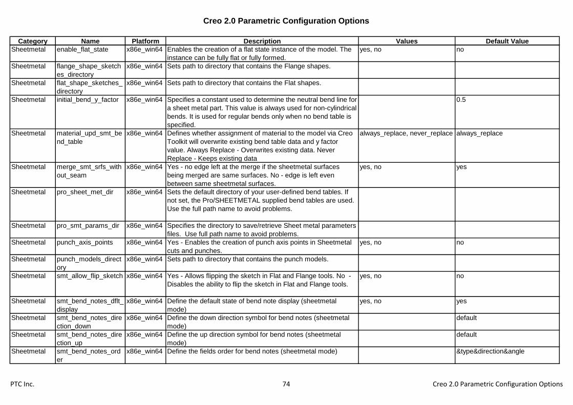
Creo 2.0 Parametric Configuration Options
Category Name Platform Description Values Default Value
Sheetmetal enable_flat_state x86e_win64 Enables the creation of a flat state instance of the model. The
instance can be fully flat or fully formed.
yes, no no
Sheetmetal flange_shape_sketch
es_directory
x86e_win64 Sets path to directory that contains the Flange shapes.
Sheetmetal flat_shape_sketches_
directory
x86e_win64 Sets path to directory that contains the Flat shapes.
Sheetmetal initial_bend_y_factor x86e_win64 Specifies a constant used to determine the neutral bend line for
a sheet metal part. This value is always used for non-cylindrical
bends. It is used for regular bends only when no bend table is
specified.
0.5
Sheetmetal material_upd_smt_be
nd_table
x86e_win64 Defines whether assignment of material to the model via Creo
Toolkit will overwrite existing bend table data and y factor
value. Always Replace - Overwrites existing data. Never
Replace - Keeps existing data
always_replace, never_replace always_replace
Sheetmetal merge_smt_srfs_with
out_seam
x86e_win64 Yes - no edge left at the merge if the sheetmetal surfaces
being merged are same surfaces. No - edge is left even
between same sheetmetal surfaces.
yes, no yes
Sheetmetal pro_sheet_met_dir x86e_win64 Sets the default directory of your user-defined bend tables. If
not set, the Pro/SHEETMETAL supplied bend tables are used.
Use the full path name to avoid problems.
Sheetmetal pro_smt_params_dir x86e_win64 Specifies the directory to save/retrieve Sheet metal parameters
files. Use full path name to avoid problems.
Sheetmetal punch_axis_points x86e_win64 Yes - Enables the creation of punch axis points in Sheetmetal
cuts and punches.
yes, no no
Sheetmetal punch_models_direct
ory
x86e_win64 Sets path to directory that contains the punch models.
Sheetmetal smt_allow_flip_sketch x86e_win64 Yes - Allows flipping the sketch in Flat and Flange tools. No -
Disables the ability to flip the sketch in Flat and Flange tools.
yes, no no
Sheetmetal smt_bend_notes_dflt_
display
x86e_win64 Define the default state of bend note display (sheetmetal
mode)
yes, no yes
Sheetmetal smt_bend_notes_dire
ction_down
x86e_win64 Define the down direction symbol for bend notes (sheetmetal
mode)
default
Sheetmetal smt_bend_notes_dire
ction_up
x86e_win64 Define the up direction symbol for bend notes (sheetmetal
mode)
default
Sheetmetal smt_bend_notes_ord
er
x86e_win64 Define the fields order for bend notes (sheetmetal mode) &type&direction&angle
PTC Inc. 74 Creo 2.0 Parametric Configuration Options
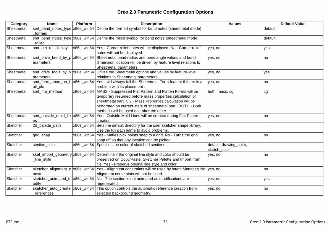
Creo 2.0 Parametric Configuration Options
Category Name Platform Description Values Default Value
Sheetmetal smt_bend_notes_type
_formed
x86e_win64 Define the formed symbol for bend notes (sheetmetal mode) default
Sheetmetal smt_bend_notes_type
_rolled
x86e_win64 Define the rolled symbol for bend notes (sheetmetal mode) default
Sheetmetal smt_crn_rel_display x86e_win64 Yes - Corner relief notes will be displayed. No - Corner relief
notes will not be displayed.
yes, no yes
Sheetmetal smt_drive_bend_by_p
arameters
x86e_win64 Sheetmetal bend radius and bend angle values and bend
dimension location will be driven by feature level relations to
Sheetmetal parameters.
yes, no no
Sheetmetal smt_drive_tools_by_p
arameters
x86e_win64 Drives the Sheetmetal options and values by feature-level
relations to Sheetmetal parameters.
yes, no yes
Sheetmetal smt_form_abort_on_f
ail_plc
x86e_win64 Yes - will always fail the Sheetmetal Form feature if there is a
problem with its placement .
yes, no no
Sheetmetal smt_mp_method x86e_win64 MASS - Suppressed Flat Pattern and Flatten Forms will be
temporary resumed before mass properties calculation of
sheetmetal part. CG - Mass Properties calculation will be
performed on current state of sheetmetal part. BOTH - Both
methods will be used one after the other.
both, mass, cg cg
Sheetmetal smt_outside_mold_lin
es
x86e_win64 Yes - Outside Mold Lines will be created during Flat Pattern
creation.
yes, no no
Sketcher 2d_palette_path x86e_win64 Sets the default directory for the user sketcher shape library.
Use the full path name to avoid problems.
Sketcher grid_snap x86e_win64 Yes - Makes pick points snap to a grid. No - Turns the grid
snap off so that any location can be picked.
yes, no no
Sketcher section_color x86e_win64 Specifies the color of sketched sections. default, drawing_color,
sketch_color
Sketcher sket_import_geometry
_line_style
x86e_win64 Determine if the original line style and color should be
preserved on Copy/Paste, Sketcher Palette and Import from
file. Yes - Preserve original line style and color.
yes, no no
Sketcher sketcher_alignment_c
onstr
x86e_win64 Yes - Alignment constraints will be used by Intent Manager; No -
Alignment constraints will not be used.
yes, no no
Sketcher sketcher_animated_m
odify
x86e_win64 No - The section is not animated as modifications are
regenerated.
yes, no yes
Sketcher sketcher_auto_create
_references
x86e_win64 This option controls the automatic reference creation from
selected background geometry.
yes, no no
PTC Inc. 75 Creo 2.0 Parametric Configuration Options
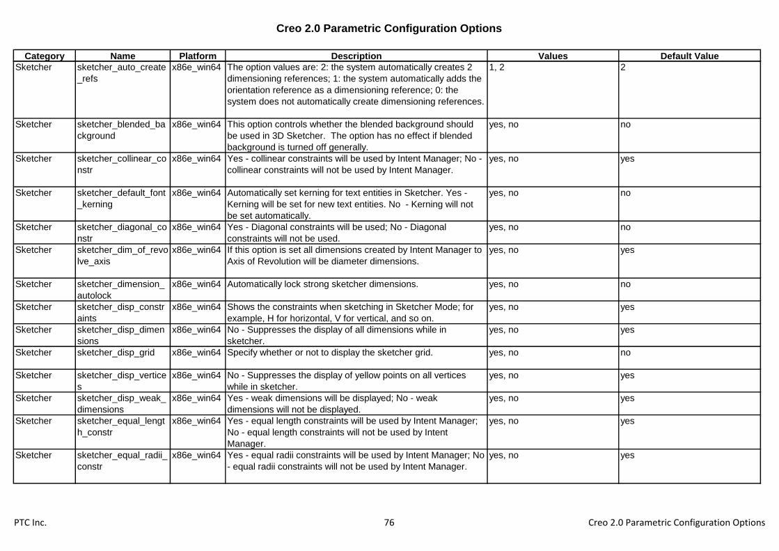
Creo 2.0 Parametric Configuration Options
Category Name Platform Description Values Default Value
Sketcher sketcher_auto_create
_refs
x86e_win64 The option values are: 2: the system automatically creates 2
dimensioning references; 1: the system automatically adds the
orientation reference as a dimensioning reference; 0: the
system does not automatically create dimensioning references.
1, 2 2
Sketcher sketcher_blended_ba
ckground
x86e_win64 This option controls whether the blended background should
be used in 3D Sketcher. The option has no effect if blended
background is turned off generally.
yes, no no
Sketcher sketcher_collinear_co
nstr
x86e_win64 Yes - collinear constraints will be used by Intent Manager; No -
collinear constraints will not be used by Intent Manager.
yes, no yes
Sketcher sketcher_default_font
_kerning
x86e_win64 Automatically set kerning for text entities in Sketcher. Yes -
Kerning will be set for new text entities. No - Kerning will not
be set automatically.
yes, no no
Sketcher sketcher_diagonal_co
nstr
x86e_win64 Yes - Diagonal constraints will be used; No - Diagonal
constraints will not be used.
yes, no no
Sketcher sketcher_dim_of_revo
lve_axis
x86e_win64 If this option is set all dimensions created by Intent Manager to
Axis of Revolution will be diameter dimensions.
yes, no yes
Sketcher sketcher_dimension_
autolock
x86e_win64 Automatically lock strong sketcher dimensions. yes, no no
Sketcher sketcher_disp_constr
aints
x86e_win64 Shows the constraints when sketching in Sketcher Mode; for
example, H for horizontal, V for vertical, and so on.
yes, no yes
Sketcher sketcher_disp_dimen
sions
x86e_win64 No - Suppresses the display of all dimensions while in
sketcher.
yes, no yes
Sketcher sketcher_disp_grid x86e_win64 Specify whether or not to display the sketcher grid. yes, no no
Sketcher sketcher_disp_vertice
s
x86e_win64 No - Suppresses the display of yellow points on all vertices
while in sketcher.
yes, no yes
Sketcher sketcher_disp_weak_
dimensions
x86e_win64 Yes - weak dimensions will be displayed; No - weak
dimensions will not be displayed.
yes, no yes
Sketcher sketcher_equal_lengt
h_constr
x86e_win64 Yes - equal length constraints will be used by Intent Manager;
No - equal length constraints will not be used by Intent
Manager.
yes, no yes
Sketcher sketcher_equal_radii_
constr
x86e_win64 Yes - equal radii constraints will be used by Intent Manager; No
- equal radii constraints will not be used by Intent Manager.
yes, no yes
PTC Inc. 76 Creo 2.0 Parametric Configuration Options

Creo 2.0 Parametric Configuration Options
Category Name Platform Description Values Default Value
Sketcher sketcher_grid_angle x86e_win64 Enter a grid angle value to override the default grid angle value. 0
Sketcher sketcher_grid_line_qu
antity
x86e_win64 Enter number of radial lines for radial grid. 12
Sketcher sketcher_grid_radius_
spacing
x86e_win64 Enter a radial grid spacing value to override the default radial
grid spacing value.
1
Sketcher sketcher_grid_type x86e_win64 Set grid type to be Cartesian or Polar. cartesian, polar cartesian
Sketcher sketcher_highlight_op
en_ends
x86e_win64 Yes - Highlights open ends of sketched entities in Sketcher. No
- Does not highlight open ends of sketched entities in Sketcher.
yes, no yes
Sketcher sketcher_import_exac
t_geom
x86e_win64 During import in sketcher use exact geometry. yes, no yes
Sketcher sketcher_known_dim
_on_ref_ent
x86e_win64 YES - create known dimensions on known geometry, NO -
create reference dimensions on known geometry
yes, no yes
Sketcher sketcher_lineup_hor_
constr
x86e_win64 Yes - line up horizontal constraints will be used by Intent
Manager; No - line up horizontal constraints will not be used by
Intent Manager.
yes, no yes
Sketcher sketcher_lineup_ver_
constr
x86e_win64 Yes - line up vertical constraints will be used by Intent
Manager; No - line up vertical constraints will not be used by
Intent Manager.
yes, no yes
Sketcher sketcher_lock_modifi
ed_dims
x86e_win64 Yes - modified dimensions will be locked; No - modified
dimensions will not be locked.
yes, no no
Sketcher sketcher_midpoint_co
nstr
x86e_win64 Yes - midpoint constraints will be used by Intent Manager; No -
midpoint constraints will not be used by Intent Manager.
yes, no yes
Sketcher sketcher_parallel_con
str
x86e_win64 Yes - parallel constraints will be used by Intent Manager; No -
parallel constraints will not be used by Intent Manager.
yes, no yes
Sketcher sketcher_perpendicul
ar_constr
x86e_win64 Yes - perpendicular constraints will be used by Intent Manager;
No - perpendicular constraints will not be used by Intent
Manager.
yes, no yes
Sketcher sketcher_point_on_en
tity_constr
x86e_win64 Yes - point on entity constraints will be used by Intent Manager;
No - point on entity constraints will not be used by Intent
Manager.
yes, no yes
Sketcher sketcher_refit_after_d
im_modify
x86e_win64 Refits section after dimension modification in 2D section or
when creating the first feature.
yes, no yes
PTC Inc. 77 Creo 2.0 Parametric Configuration Options

Creo 2.0 Parametric Configuration Options
Category Name Platform Description Values Default Value
Sketcher sketcher_rel_accurac
y
x86e_win64 Enter a sketcher relative accuracy. -1
Sketcher sketcher_same_point
_constr
x86e_win64 Yes - same points constraints will be used by Intent Manager;
No - same points constraints will not be used by Intent
Manager.
yes, no yes
Sketcher sketcher_save_previe
w_image
x86e_win64 This option controls whether section files should be saved with
embedded image information which can be used to preview
sections in File/Open dialog.
yes, no no
Sketcher sketcher_set_grid_me
thod
x86e_win64 "Automatic" - grid spacing will be automatically set, "Manual" -
grid spacing will be manually set.
dynamic, static dynamic
Sketcher sketcher_set_grid_x_
major
x86e_win64 Enter the number of grid lines per major line in x axis. 5
Sketcher sketcher_set_grid_x_
spacing
x86e_win64 Enter an x-grid spacing value to override the default x-grid
spacing value.
1
Sketcher sketcher_set_grid_y_
major
x86e_win64 Enter the number of grid lines per major line in y axis. 5
Sketcher sketcher_set_grid_y_
spacing
x86e_win64 Enter a y-grid spacing value to override the default y-grid
spacing value.
1
Sketcher sketcher_shade_clos
ed_loops
x86e_win64 yes-closed loops in sketcher will be displayed as shaded, no-
closed loops in sketcher will not be displayed as shaded
yes, no yes
Sketcher sketcher_starts_in_2d x86e_win64 Defines initial model orientation in Sketcher mode. Yes - (2D
orientation) Looking directly at section (sketching) plane. No -
(Orientation unchanged) Sketch directly on the 3D part.
yes, no no
Sketcher sketcher_symmetric_
constr
x86e_win64 Yes - symmetric constraints will be used by Intent Manager; No
- symmetric constraints will not be used by Intent Manager.
yes, no yes
Sketcher sketcher_tangent_con
str
x86e_win64 Yes - tangent constraints will be used by Intent Manager; No -
tangent constraints will not be used by Intent Manager.
yes, no yes
Sketcher sketcher_undo_reorie
nt_view
x86e_win64 Controls the ability to Undo view reorientation while in
Sketcher. Yes - it is possible to Undo view reorientation in
Sketcher.
yes, no no
Sketcher sketcher_undo_stack
_limit
x86e_win64 Sketcher saves a copy of each function performed. The
number of possible saved functions depend on the number
specified in the option. The undo menu can be used to remove
the stored functions.
200
PTC Inc. 78 Creo 2.0 Parametric Configuration Options

Creo 2.0 Parametric Configuration Options
Category Name Platform Description Values Default Value
System allow_float_opt_check
out
x86e_win64 Yes - Allows checkout failure for floating modules. yes, no no
System auto_traceback x86e_win64 "always": a traceback file will be generated when a fatal error
occurs. "yes", "ask": ask the user whether to generate a
traceback. "no", "never": no traceback will be generated.
yes, no, never, ask, always always
System cmdmgr_trail_output x86e_win64 Trail file and mapkey output will include system instructions
that are independent of user interface configuration when
available (typically menu bar and toolbar options).
yes, no yes
System cpus_to_use x86e_win64 Set up the number of threads including main thread 2
System enable_tree_indep x86e_win64 Setup whether tree customization will allow separating the tree
window from Creo Parametric window.
yes, no no
System export_report_format x86e_win64 Controls the format of the exported reports displayed in the
embedded browser. Rich Text - Exports the report in Rich Text
format, Comma Delimited - Exports the report in Comma
Delimited format.
comma_delimited, rich_text comma_delimited
System general_undo_stack_l
imit
x86e_win64 Setup the default number of entries in the top level Undo/Redo
(default = 50).
50
System graphics x86e_win64 Sets the optional graphics environment used by certain
platforms for running Creo Parametric. Refer to the Installation
Guide for a list of defaults and optional graphics.
opengl, x_windows, win32_gdi,
d3d
no_graphics
System overlays_enabled x86e_win64 Yes - Enables Creo Parametric screens and menus to be
placed on different overlay layers of the hardware graphics
card. This frees memory for Creo Parametric use.
yes, no no
System pick_aperture_radius x86e_win64 Specifies the size of the area about the mouse when making
selections. Units are 1/1000 of screen size.
7
System protable_in_backgrou
nd
x86e_win64 Yes - Starts Pro/TABLE editor in the background. Reduces
time between pressing a menu button that uses Pro/TABLE
and entering the data.
yes, no yes
System saveunders_enabled x86e_win64 Yes - Enables Creo Parametric popup helptext and menus to
retain the portion of the window they obscure to be used to
restore the window image when they are dismissed.
yes, no yes
System set_trail_single_step x86e_win64 Yes - Enables a trail file to be single-stepped by entering
<CR>.
yes, no no
PTC Inc. 79 Creo 2.0 Parametric Configuration Options

Creo 2.0 Parametric Configuration Options
Category Name Platform Description Values Default Value
System tablet_device_name x86e_win64 Specifies the name of a digitizing tablet.
System trail_delay x86e_win64 Sets a delay in seconds between trail file steps.
System trail_dir x86e_win64 Instructs Creo Parametric to create its trail file in the specified
directory rather than in the startup directory.
System train_file_path x86e_win64 Specifies the default directory for training files. The path name
must start from the root of the directory, for example,
/home/users/library/training.
System use_software_opengl x86e_win64 Use MS-Windows software OpenGL. In some cases this may
avoid graphics card specific problems at the expense of
performance.
yes, no no
System web_browser_history
_days
x86e_win64 Enter number of days to store history records. 20
System web_browser_homep
age
x86e_win64 Enter location of Creo Parametric browser home page. <creo_loadpoint>\help\usascii\res
ource_center_index.html
System web_browser_in_sep
arate_window
x86e_win64 Specifies whether Creo Parametrics web browser should be
launched as a separate window. When set to Yes the browser
will be displayed as a separate window. The default, No, will
result in the browser being embedded in the Creo Parametric
application window
yes, no no
System windows_browser_typ
e
x86e_win64 Select the type of embedded browser to use. ie_in_process,
ie_in_sep_process,
mozilla_based_browser
ie_in_process
User Interface ae_propagate_detail_
dependency
x86e_win64 Sets the AE detail dependency for AE's that are locally
propagated. If set to independent, the AE's parameter call outs
will update to other propagated AEs parameters.
dependent, independent dependent
User Interface af_copy_references_fl
ag
x86e_win64 Toggle display of Copy References column in Annotation
Feature definition dialog
yes, no no
User Interface allow_confirm_windo
w
x86e_win64 Display a confirmation window when exiting Creo Parametric.
This enables you to use the mouse to confirm/cancel exiting
Creo Parametric.
yes, no yes
User Interface auto_ae_param_file x86e_win64 Define path and file name of external file used to define
parameters that are automatically created in all Annotation
Elements.
User Interface auto_include_annot_p
lane
x86e_win64 Control the default setting of the check box in the Propagate
annotation dialog box which controls whether to pass all
annotations plane references.
yes, no yes
PTC Inc. 80 Creo 2.0 Parametric Configuration Options

Creo 2.0 Parametric Configuration Options
Category Name Platform Description Values Default Value
User Interface auto_propagate_ae x86e_win64 Yes - causes the automatic, local propagation of AE's after a
supported feature has been created.
yes, no no
User Interface auxapp_popup_menu
_info
x86e_win64 Enable display of popup menu info in the trail file. yes, no no
User Interface bm_graph_tool x86e_win64 BMX graph tool default, excel_linked,
excel_embedded
default
User Interface bmgr_pref_file x86e_win64 Specifies the location of the Graph Tool preference file.
User Interface button_name_in_help x86e_win64 Yes - The name and menu of any selected menu option
displays, in English, in the help text associated with that button.
yes, no no
User Interface default_font x86e_win64 Sets font for text other than menu bar, menus and their
children, and pop-up menus and help. Add comma-delimited
variables in any order (italic bold, 24, times or 24, times, italic
bold have the same effect). Any omitted variable uses standard
setting.
User Interface dialog_translation x86e_win64 Specifies the language in which the dialog display when
running non-English version of Creo Parametric.
yes, no yes
User Interface drm_policy_server x86e_win64 Allows a user to preset the server policy that is to be used
when Apply Policy command is utilized.
User Interface enable_popup_help x86e_win64 Controls pop-up help in dialog boxes. Yes - Help enabled. No -
Help disabled.
yes, no yes
User Interface fonts_size x86e_win64 Determines the relative size of the text in menus and dialog
boxes. You must restart Creo Parametric for the change to
take effect.
medium, small, large
User Interface help_translation x86e_win64 Specifies the language in which the short help messages
display when running non-English versions of Creo Parametric.
Yes - Display in native language. No - Display in English.
yes, no yes
User Interface iconify_entire_pro x86e_win64 Determines how many other Creo Parametric windows/menus
are iconified when one window is iconified. Yes - All the
windows and menus are iconified. No - Only the selected
window is iconified.
yes, no yes
User Interface initial_drm_warning x86e_win64 Warns the user that they are initiating a DRM session. When
set to "no", this warning dialog will be skipped.
yes, no yes
User Interface kbd_cmd_abbreviatio
n
x86e_win64 On - Enables use of abbreviations when entering menu
commands from the keyboard.
off, on off
PTC Inc. 81 Creo 2.0 Parametric Configuration Options

Creo 2.0 Parametric Configuration Options
Category Name Platform Description Values Default Value
User Interface kbd_selection x86e_win64 Provides the ability to select locations in the graphics area via
the keyboard. Yes - Selection in the graphics area may be
performed via the keyboard. No - Selection in the graphics
area requires a mouse.
yes, no no
User Interface load_ui_customization
_run_dir
x86e_win64 Enables the loading of the UI customization file (.ui) if located
in the run directory
yes, no no
User Interface mdl_tree_cfg_file x86e_win64 Specifies the Model Tree configuration file to be loaded when
Creo Parametric is started.
User Interface menu_font x86e_win64 Specify font used in the Creo Parametric menu bar, menus,
and all their children. Specify the comma-delimited variables in
any order (italic bold, 24, times or 24, times, italic bold have the
same effect). Any omitted variable uses the standard setting.
User Interface menu_manager_positi
on
x86e_win64 Controls the position of the Menu Manager. outside - Top left
corner of Menu Manager is aligned to top right corner of
window, inside - Top right corner of Menu Manager is aligned
to top right corner of graphics area, adaptive - Menu Manager
is positioned outside if there is enough room, otherwise it is
positioned inside.
inside, outside, adaptive adaptive
User Interface menu_mapper_locatio
n
x86e_win64 Specify your own URL for the Menu Mapper button in the help
menu.
User Interface menu_translation x86e_win64 Specifies the language in which the menus display when
running non-English version of Creo Parametric.
yes, no, both yes
User Interface modeltree_show_gen
_of_instance
x86e_win64 Determines whether the generic name is displayed as an
extension of the instance name in the model tree and other
model name lists.
yes, no yes
User Interface msg_translation x86e_win64 Specifies language in which Messages are displayed when
running non-English version of Creo Parametric.
yes, no yes
User Interface native_kbd_macros x86e_win64 Specifies support of keyboard macros written in native
language (for example, German).
yes, no no
User Interface new_parameter_ui x86e_win64 Enable the new parameter editor and user interface. yes, no yes
User Interface new_relation_ui x86e_win64 Enable the new relations editor and user interface. yes, no yes
User Interface online_resources_loc
ation
x86e_win64 Specify your own URL for the Online Resources button in the
help menu.
User Interface param_dec_places x86e_win64 Sets the number of decimal places (0-14) to display in
parameters.
6
PTC Inc. 82 Creo 2.0 Parametric Configuration Options

Creo 2.0 Parametric Configuration Options
Category Name Platform Description Values Default Value
User Interface parameter_dialog_set
up_file
x86e_win64 Setup for the parameter dialog configuration file.
User Interface part_table_editor x86e_win64 Sets the editor that is used to edit notebook parameter tables.
Protab - Use Pro/TABLE. Editor - Use the system editor (refer
to pro_editor_command).
protab, editor, excel
User Interface pattern_relations_cop
y
x86e_win64 Determines whether relations of pattern leader are inherited by
pattern members.
yes, no yes
User Interface popuphelp_font x86e_win64 Specify font used in the Creo Parametric pop-up help. Add the
comma-delimited variables in any order (italic bold, 24, times or
24, times, italic bold have the same effect). Any omitted
variable uses the standard setting.
User Interface pro_editor_command x86e_win64 Enables use of an editor other than the system editor when the
option editor has been specified as the value for the options
part_table_editor or relation_file_editor.
User Interface prompt_on_exit x86e_win64 Determines if you are prompted to save objects when exiting a
Creo Parametric session.
yes, no no
User Interface propagate_inactive_a
nnotation
x86e_win64 Yes - causes the propagation of inactive annotation. yes, no yes
User Interface provide_pick_messag
e_always
x86e_win64 No - A message describing the (pre)selected item is provided
only while querying. Yes - A message describing the selected
item is provided in all cases (i.e. even when Query is not used).
yes, no no
User Interface relation_file_editor x86e_win64 Sets the editor used to edit relations. protab, editor editor
User Interface reserved_menu_spac
e
x86e_win64 Reserves space for extra menus to the right of the Creo
Parametric window (0.0-4.0). This option overrides
windows_scale.
1
User Interface right_mouse_button_
popup
x86e_win64 Specify whether or not the right mouse button pop up menu is
available or not.
yes, no yes
User Interface selection_dragger_dis
play_max
x86e_win64 Threshold for the number of simultaneously selected items to
not display draggers.
100
User Interface set_menu_width x86e_win64 Determines width of menu manager panels. Default value is
equivalent to 8 character widths. Acceptable range is from 8 to
20. Values lower than 8 and higher than 20 are ignored.
-1
User Interface summary_help x86e_win64 Refers to the one-line help Messages that are either displayed
or not displayed.
yes, no no
PTC Inc. 83 Creo 2.0 Parametric Configuration Options
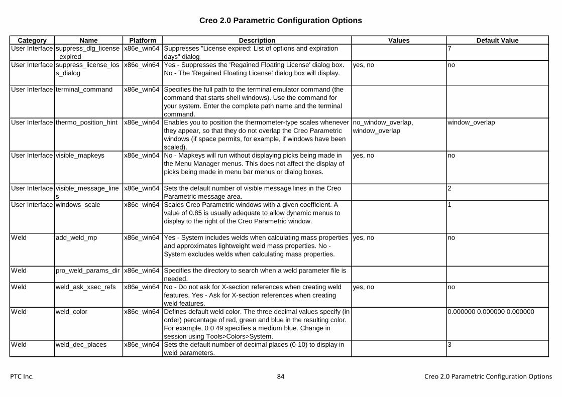
Creo 2.0 Parametric Configuration Options
Category Name Platform Description Values Default Value
User Interface suppress_dlg_license
_expired
x86e_win64 Suppresses "License expired: List of options and expiration
days" dialog
7
User Interface suppress_license_los
s_dialog
x86e_win64 Yes - Suppresses the 'Regained Floating License' dialog box.
No - The 'Regained Floating License' dialog box will display.
yes, no no
User Interface terminal_command x86e_win64 Specifies the full path to the terminal emulator command (the
command that starts shell windows). Use the command for
your system. Enter the complete path name and the terminal
command.
User Interface thermo_position_hint x86e_win64 Enables you to position the thermometer-type scales whenever
they appear, so that they do not overlap the Creo Parametric
windows (if space permits, for example, if windows have been
scaled).
no_window_overlap,
window_overlap
window_overlap
User Interface visible_mapkeys x86e_win64 No - Mapkeys will run without displaying picks being made in
the Menu Manager menus. This does not affect the display of
picks being made in menu bar menus or dialog boxes.
yes, no no
User Interface visible_message_line
s
x86e_win64 Sets the default number of visible message lines in the Creo
Parametric message area.
2
User Interface windows_scale x86e_win64 Scales Creo Parametric windows with a given coefficient. A
value of 0.85 is usually adequate to allow dynamic menus to
display to the right of the Creo Parametric window.
1
Weld add_weld_mp x86e_win64 Yes - System includes welds when calculating mass properties
and approximates lightweight weld mass properties. No -
System excludes welds when calculating mass properties.
yes, no no
Weld pro_weld_params_dir x86e_win64 Specifies the directory to search when a weld parameter file is
needed.
Weld weld_ask_xsec_refs x86e_win64 No - Do not ask for X-section references when creating weld
features. Yes - Ask for X-section references when creating
weld features.
yes, no no
Weld weld_color x86e_win64 Defines default weld color. The three decimal values specify (in
order) percentage of red, green and blue in the resulting color.
For example, 0 0 49 specifies a medium blue. Change in
session using Tools>Colors>System.
0.000000 0.000000 0.000000
Weld weld_dec_places x86e_win64 Sets the default number of decimal places (0-10) to display in
weld parameters.
3
PTC Inc. 84 Creo 2.0 Parametric Configuration Options

Creo 2.0 Parametric Configuration Options
Category Name Platform Description Values Default Value
Weld weld_edge_prep_driv
en_by
x86e_win64 Determines if the edge preparation feature is created in the
part or the assembly level.
part, assembly part
Weld weld_edge_prep_groo
ve_angle
x86e_win64 Specifies an initial default value for the angle cut edge
preparation.
45
Weld weld_edge_prep_groo
ve_depth
x86e_win64 Specifies an initial default value for the edge preparation depth. 0.25
Weld weld_edge_prep_inst
ance
x86e_win64 Controls whether a family table instance is created for edge
preparation. Yes - Instances of the components that receive
edge preparation are created.
yes, no
Weld weld_edge_prep_nam
e_suffix
x86e_win64 Specifies the suffix name for the instance that will be created
during edge preparation. Part name plus extension makes the
instance name.
_noep
Weld weld_edge_prep_root
_open
x86e_win64 Specifies an initial default value for the root opening edge
preparation.
0.25
Weld weld_edge_prep_visib
ility
x86e_win64 Applies only if weld_edge_prep is set to Yes. Generic - Edge
preparation features are resumed in the generic and
suppressed in the instance. Instance - Edge preparation
features are suppressed in the generic and resumed in the
instance.
generic, instance
Weld weld_geom_type_def
ault
x86e_win64 Sets the default weld geometry type. light, surface surface
Weld weld_notch_corner_ra
dius
x86e_win64 Specifies an initial default value for the radius at weld notch
corner.
0.1
Weld weld_notch_height x86e_win64 Specifies an initial default value for the weld notch height. 0.4
Weld weld_notch_radius x86e_win64 Specifies an initial default value for the weld notch radius. 0.5
Weld weld_notch_width x86e_win64 Specifies an initial default value for the weld notch width. 0.5
Weld weld_ui_standard x86e_win64 Specifies standard for welding user interface. ANSI - Use ANSI
standards. ISO - Use ISO standards.
ansi, iso ansi
Without
category
accessory_window_di
splay
x86e_win64 Docked - Displays the accessory window embedded in the
active window. Undocked - Displays the accessory window as
a standalone window.
undocked, docked docked
Without
category
acis_out_version x86e_win64 Allows the user to choose ACIS export version. 4, 5 5
Without
category
advanced_style_surfa
ce_edit
x86e_win64 Use advanced options by default for Surface Edit in Style. yes, no no
PTC Inc. 85 Creo 2.0 Parametric Configuration Options

Creo 2.0 Parametric Configuration Options
Category Name Platform Description Values Default Value
Without
category
aec_parameter_file x86e_win64 Specifies the file name of the user defined piping parameter
codes.
Without
category
allow_delete_many_in
_drawings
x86e_win64 Make the Delete Many command available in drawing mode.
The Delete Many command is not supported by undo but can
improve performance when deleting a significant number of
items.
yes, no no
Without
category
allow_ref_scope_cha
nge
x86e_win64 No - Displays the message "Reference scope changes are
prohibited by the configuration file settings" when the Ref
Scope user interface is changed.
yes, no yes
Without
category
allow_workpiece_silho
uette
x86e_win64 Determines if the workpiece is allowed for Silhouette Mach
Window creation. NO - only reference part is allowed; YES -
both workpiece and reference part are allowed; AUTO - only
workpiece is allowed.
yes, no, auto no
Without
category
animation_imported_p
bk_dir
x86e_win64 Sets the default directory for the playback files to be used for
Imported Animation.
Without
category
arc_radius_limit x86e_win64 Sets the upper limit for a radius in a CIRCLE statement of NCL
file. The value must be positive. If not, 10*part_size is used.
-1
Without
category
ask_designate_owner
s
x86e_win64 Show the both required and optional owners to be designated. yes, no yes
Without
category
assemble_module_in
_rep
x86e_win64 Retrieves the assembled module to CSA in a specified
representation.
representative module variant
Without
category
atb_search_path x86e_win64 Extends search path for ATB Update and ATB Check Status
commands.
Without
category
attach_menumanager x86e_win64 Setup menu manager attachment to the main Creo Parametric
window.
yes, no no
Without
category
auto_eval_current_cnf
g_rule
x86e_win64 If the option is "yes" simplified representation would be updated
each time on retrieve/regeneration if it contains current
configuration rule.
yes, no yes
Without
category
auto_show_3d_detail
_items
x86e_win64 When set to yes, AEs parallel to the view will be displayed
while creating a new view.
yes, no yes
Without
category
bmx_param_restrictio
ns
x86e_win64 Restricted parameters automatically violate constraints in any
Design Study
yes, no yes
Without
category
boeing_extract_bundl
e
x86e_win64 Yes - Uses the extract bundle algorithm. No - Does not use the
extract bundle algorithm.
yes, no no
Without
category
check_udf_int_key x86e_win64 Yes - updates UDF internal keys upon group's retrieval. No -
skips keys update.
yes, no yes
PTC Inc. 86 Creo 2.0 Parametric Configuration Options
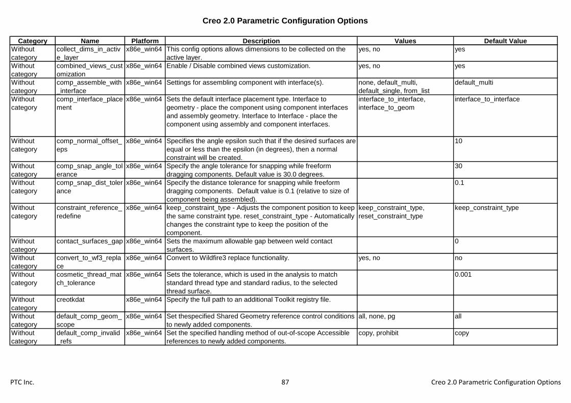
Creo 2.0 Parametric Configuration Options
Category Name Platform Description Values Default Value
Without
category
collect_dims_in_activ
e_layer
x86e_win64 This config options allows dimensions to be collected on the
active layer.
yes, no yes
Without
category
combined_views_cust
omization
x86e_win64 Enable / Disable combined views customization. yes, no yes
Without
category
comp_assemble_with
_interface
x86e_win64 Settings for assembling component with interface(s). none, default_multi,
default_single, from_list
default_multi
Without
category
comp_interface_place
ment
x86e_win64 Sets the default interface placement type. Interface to
geometry - place the component using component interfaces
and assembly geometry. Interface to Interface - place the
component using assembly and component interfaces.
interface_to_interface,
interface_to_geom
interface_to_interface
Without
category
comp_normal_offset_
eps
x86e_win64 Specifies the angle epsilon such that if the desired surfaces are
equal or less than the epsilon (in degrees), then a normal
constraint will be created.
10
Without
category
comp_snap_angle_tol
erance
x86e_win64 Specify the angle tolerance for snapping while freeform
dragging components. Default value is 30.0 degrees.
30
Without
category
comp_snap_dist_toler
ance
x86e_win64 Specify the distance tolerance for snapping while freeform
dragging components. Default value is 0.1 (relative to size of
component being assembled).
0.1
Without
category
constraint_reference_
redefine
x86e_win64 keep_constraint_type - Adjusts the component position to keep
the same constraint type. reset_constraint_type - Automatically
changes the constraint type to keep the position of the
component.
keep_constraint_type,
reset_constraint_type
keep_constraint_type
Without
category
contact_surfaces_gap x86e_win64 Sets the maximum allowable gap between weld contact
surfaces.
0
Without
category
convert_to_wf3_repla
ce
x86e_win64 Convert to Wildfire3 replace functionality. yes, no no
Without
category
cosmetic_thread_mat
ch_tolerance
x86e_win64 Sets the tolerance, which is used in the analysis to match
standard thread type and standard radius, to the selected
thread surface.
0.001
Without
category
creotkdat x86e_win64 Specify the full path to an additional Toolkit registry file.
Without
category
default_comp_geom_
scope
x86e_win64 Set thespecified Shared Geometry reference control conditions
to newly added components.
all, none, pg all
Without
category
default_comp_invalid
_refs
x86e_win64 Set the specified handling method of out-of-scope Accessible
references to newly added components.
copy, prohibit copy
PTC Inc. 87 Creo 2.0 Parametric Configuration Options

Creo 2.0 Parametric Configuration Options
Category Name Platform Description Values Default Value
Without
category
default_comp_module
_geom_scope
x86e_win64 Set the specified Shared Geometry reference control
conditions to newly added components for configurable
structure.
all, none, pg, tagged tagged
Without
category
default_comp_scope_
setting
x86e_win64 Set the specified Accessible reference control conditions to
newly added components.
all, none, subassemblies,
skeleton_model
all
Without
category
default_comp_skel_g
eom_scope
x86e_win64 Set the specified Shared Geometry reference control
conditions to newly added Skeleton components.
all, none, pg all
Without
category
default_comp_skel_s
cope_setting
x86e_win64 Set the specified Accessible reference control conditions to
newly added Skeleton components.
all, none, subassemblies,
skeleton_model
all
Without
category
default_ext_ref_scope x86e_win64 Set default scope for externally referenced models. All - Any
model. None - Only current model and children. Skeletons -
Any component in model's assembly and higher skeletons on
branch. Subassembly - Only components and children in
model's assembly.
all, none, subassemblies,
skeleton_model
all
Without
category
default_geom_analysi
s_type
x86e_win64 Default save type for geometry analysis. quick, saved, feature quick
Without
category
default_geom_scope x86e_win64 Default value for Geometry Scope allowed for referencing. all, pg_if_exists, pg_only all
Without
category
default_obj_constraint
s_scope
x86e_win64 Set the specified Shared Placement reference control
conditions to newly created models if template models were not
used.
all, none, interfaces all
Without
category
default_obj_module_c
onstr_scope
x86e_win64 Set the specified Shared Placement reference control
conditions to newly created models for configurable structure if
template models were not used.
all, none, interfaces, tagged tagged
Without
category
default_obj_module_g
eom_scope
x86e_win64 Set the specified Shared Geometry reference control
conditions to newly created models for configurable structure
modules if template models were not used.
all, none, pg, tagged all
Without
category
default_object_geom_
scope
x86e_win64 Set the specified Shared Geometry reference control
conditions to newly created models if template models were not
used.
all, none, pg all
Without
category
default_object_invalid
_refs
x86e_win64 Sets default condition for reference handling. Prohibit - System
will abort all attempts to create ext. reference that violates
scope. Copy - System will issue warning upon all attempts to
create ext. reference that violates scope.
copy, prohibit copy
PTC Inc. 88 Creo 2.0 Parametric Configuration Options

Creo 2.0 Parametric Configuration Options
Category Name Platform Description Values Default Value
Without
category
default_object_scope
_setting
x86e_win64 Set default condition for reference control. All - Any model.
None - Only current model and children. Skeletons - Any
component in model's assembly ang higher skeletons on
branch. Subassembly - Only components and children in
model's assembly.
all, none, subassemblies,
skeleton_model
all
Without
category
default_placement_sc
ope
x86e_win64 Default value for Component Placement Reference filter. all, intrf_if_exists, intrf_only all
Without
category
default_ref_current_m
odule_vrnt
x86e_win64 Allow references to current design solution only. yes, no yes
Without
category
designate_model_ite
m_params
x86e_win64 When an object is designated, all parameters belonging to that
object will be automatically designated as well.
yes, no no
Without
category
disp_in_open_rep_cre
ate
x86e_win64 Simplified Rep to display initially in Open Rep Create: "No" for
none, "Yes" for graphics rep, or "Default Rep" to display the rep
indicated by option "open_simplified_rep_by_default".
yes, no, default rep no
Without
category
display_all_dims x86e_win64 Controls the display of dimensions during dynamic edit. yes, no yes
Without
category
display_combined_vie
ws
x86e_win64 Display combined view tabs by default yes, no no
Without
category
display_ie8_warning_
dialog
x86e_win64 Show/Hide the warning dialog related to Internet Explorer 8
running in Compatibility Mode
yes, no yes
Without
category
display_images x86e_win64 Display images outside of Style feature yes, no yes
Without
category
display_pdm_server_
quick_view
x86e_win64 Yes - display summary view of PDM information for items in
session. It applies to ProductPoint only.
yes, no yes
Without
category
display_popup_viewer x86e_win64 No- disable popup viewer, File_Open_Only: display popup
viewer only in the file open dialog, Yes: display popup viewer in
file open dialog, model tree and in Server Quick View dialog
yes, no, file_open_only file_open_only
Without
category
display_sketch_dims x86e_win64 Controls the display of sketch dimensions during dynamic edit. yes, no yes
Without
category
dm_enable_impex_att
ributes
x86e_win64 yes, no no
Without
category
dm_enable_simple_i
mport_export
x86e_win64 Enable a simplified method of import/export between disk and
Workspace.
yes, no yes
PTC Inc. 89 Creo 2.0 Parametric Configuration Options

Creo 2.0 Parametric Configuration Options
Category Name Platform Description Values Default Value
Without
category
dm_nc_process x86e_win64 Sets output of NC process information as content on the NC
Assembly CAD Document in XML Format. Yes - Outputs the
file whenever CAD Document is Saved. No - Does not output
the file.
yes, no no
Without
category
dm_nc_references x86e_win64 Sets whether reference relationships will be created in
Windchill between the manufacturing model and its
deliverables(CL file, tape file and DMIS file).
yes, no yes
Without
category
dwg_unicode_conv_la
ng_scope
x86e_win64 Specifies scope of the option
'dwg_unicode_conversion_language'. '2D' to apply to 2D
models only, 'ALL' to apply to all models.
all, 2d 2d
Without
category
ecad_load_filtered_ho
les_to_ui
x86e_win64 Controls whether "ECAD import holes configs"
(ecad_pin_hole_import & ecad_via_hole_import) will remove
holes completely from the import (default) or just pre-set the
holes filter UI condition.
yes, no no
Without
category
ecad_outline_holes_e
xp_method
x86e_win64 Select how holes that are placed on the board outline be
exported.
default, arcs default
Without
category
edge_tess_quality x86e_win64 Set the accuracy level for arc tessllation. high, medium, low low
Without
category
enable_3dmodelspac
e_browser_tab
x86e_win64 Yes - Display 3D ModelSpace tab in the browser when Creo
Parametric starts. No - Display 3D ModelSpace tab only when
you click a 3D ModelSpace link in the navigator.
yes, no yes
Without
category
enable_face_preselec
tion
x86e_win64 Controls the ability to "pre-select" faces/datums as an entry to
Sketch based features such as Extrude, Revolve (input to the
internal sketch).
yes, no yes
Without
category
enable_face_thread_t
urning
x86e_win64 Allows/disallows face option for thread turning sequence. yes, no no
Without
category
enable_fsaa x86e_win64 Enable OpenGL full screen anti-aliasing. off, 2, 4, 8, 16, 32 off
Without
category
enable_learning_conn
ector
x86e_win64 Enable the Learning Connector, which provides context
specific access to videos, training, help topics, and technical
support content. When enabled, the Learning Connector is
added to the ribbon bar next to Help.
yes, no yes
Without
category
enable_obsoleted_fea
tures
x86e_win64 yes, no no
Without
category
enable_offset_fan_cur
ve
x86e_win64 Enables fan curve option for offset tool. yes, no no
PTC Inc. 90 Creo 2.0 Parametric Configuration Options

Creo 2.0 Parametric Configuration Options
Category Name Platform Description Values Default Value
Without
category
enable_opengl_shade
r
x86e_win64 Enable OpenGL Phong lighting. yes, no yes
Without
category
enable_sociallink x86e_win64 Allow Windchill SocialLink to connect with Creo Parametric.
When enabled SocialLink commands will be added to the
Application Menu and the Ribbon bar. Enter "Yes" to enable
SocialLink, and "No" to disable it
yes, no yes
Without
category
esr_mass_properties x86e_win64 Defines whether to include all immediate components of
external simplified rep into Mass Properties calculations or
only defined state of design assembly.
design_only, extended design_only
Without
category
expand_all_with_nest
ed_layers
x86e_win64 Yes - expand all including nested sub layers. yes, no yes
Without
category
fasthlr_drawing x86e_win64 Specifies whether fast hidden line removal is on/off by default. yes, no no
Without
category
file_dialog_units_clas
s
x86e_win64 Sets the units for manikin attributes displayed in the File Open
dialog.
mks, ips mks
Without
category
file_timestamp_format x86e_win64 Controls the format of time stamps in file dialogs and the folder
browser. The format for the setting is a string consisting of up
to seven portions: the year, the month, and the date, the hours,
minutes, seconds and am/pm designator. You can enter the
portions in any order.
%dd-%mmm-%yy %hh:%mi:%ss
%pm
Without
category
group_repl_with_recy
cle
x86e_win64 Yes - enables new UDF replacement with family table
instances that prevents children failures. No - UDF
replacement will work in the same manner as Wildfire 3.0 and
earlier releases.
yes, no yes
Without
category
group_replace_renam
e
x86e_win64 Yes - updates replaced group name with replacement group
name. No - preserves existing name of the group being
replaced if it is a user-given name.
yes, no yes
Without
category
hdic_export_v5_seco
ndary_cgr
x86e_win64 In HDIC export for CATIA V5 allows to attach CGR as a
secondary content
yes, no no
Without
category
hdic_export_v5_to_w
s_enable
x86e_win64 Enables HDIC export for CATIA V5 to Workspace. yes, no no
Without
category
idd_repair_tangency x86e_win64 Sets the default state of the "Repair Tangency" checkbox in the
Repair and Match tools
yes, no no
Without
category
ignore_all_ref_scope_
settings
x86e_win64 Controls whether object-specific reference scope settings are
ignored or not. Environment scope settings will still be
enforced. See also allow_ref_scope_change and
default_ext_ref_scope
yes, no no
PTC Inc. 91 Creo 2.0 Parametric Configuration Options

Creo 2.0 Parametric Configuration Options
Category Name Platform Description Values Default Value
Without
category
ignore_export_geom_
declaration
x86e_win64 Ignore Export Geometry settings. yes, no no
Without
category
include_all_tools_in_li
st
x86e_win64 Show/hide inapplicable cutting tools in mfg sequence UI. yes, no no
Without
category
intf_pdf_u3d_create_
u3d_files
x86e_win64 YES - When exporting a Creo Parametric model as PDF U3D
file, create a U3D file of the same name as the PDF file.
yes, no no
Without
category
intf2d_out_blanked_la
yers
x86e_win64 Enables export of blanked layer entities. If an entity is placed
on a layer that is blanked and this option is set to YES, the
entity will be exported.
yes, no no
Without
category
intf3d_out_catia_v5_v
ersion
x86e_win64 Allows the user to switch between the default and alternate
converter version for export to CATIA V5
16, 17, 18, 19, 20, 21, 22 16
Without
category
intf3d_out_jt_config_n
ame
x86e_win64 Name of JT configuration file.
Without
category
intf3d_out_jt_config_p
ath
x86e_win64 Path to JT configuration file.
Without
category
jlink_java_command x86e_win64 Specifies a command to start JRE for J-Link. May contain
arguments and environment variables. Overrides the default,
see also jlink_java2.
Without
category
js_error_policy x86e_win64 Control the display and execution of the java script error
dialogs. If the dialog is presented, the user can choose
whether to stop or continue running the script.
show, suppress_continue,
supress_stop
Without
category
keep_model_in_open
_window
x86e_win64 Controls whether a model is displayed in its window when the
accessory window is open.
yes, no no
Without
category
keep_style_items_hid
den_on_exit
x86e_win64 Keep style entities hidden after exiting of the Style feature
definition.
yes, no no
Without
category
last_session_directory
_path
x86e_win64 Sets the directory that holds the temp files for the session
recording mechanism.
<work_dir>\appdata\roaming\ptc\
proengineer\wildfire\.wf\.settings
Without
category
last_session_retrieval x86e_win64 Yes - Activates recording mechanism that enables the session
to be retrieved during the next session. No - The recording
mechanism is not available and the session can not be
retrieved.
yes, no yes
Without
category
layer_rule_retrieve_ob
jects
x86e_win64 This option controls whether or not the system will retrieve
additional objects needed to evaluate a layer rule. OK tells the
system to retrieve the objects. Cancel stops evaluation of the
rule.
ok, cancel, promt promt
PTC Inc. 92 Creo 2.0 Parametric Configuration Options
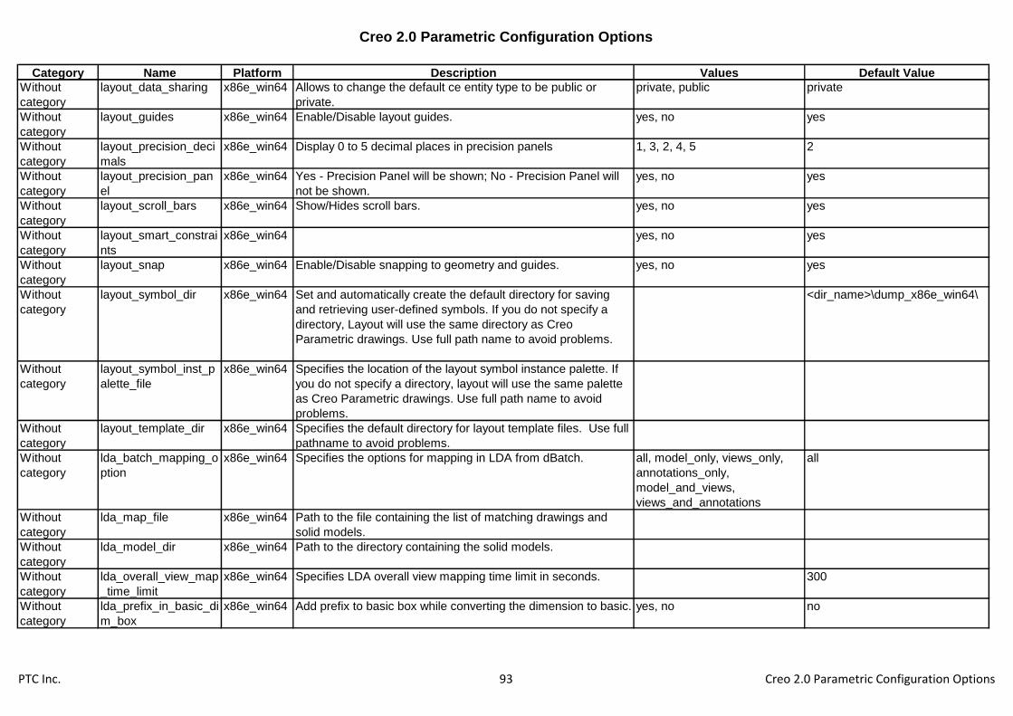
Creo 2.0 Parametric Configuration Options
Category Name Platform Description Values Default Value
Without
category
layout_data_sharing x86e_win64 Allows to change the default ce entity type to be public or
private.
private, public private
Without
category
layout_guides x86e_win64 Enable/Disable layout guides. yes, no yes
Without
category
layout_precision_deci
mals
x86e_win64 Display 0 to 5 decimal places in precision panels 1, 3, 2, 4, 5 2
Without
category
layout_precision_pan
el
x86e_win64 Yes - Precision Panel will be shown; No - Precision Panel will
not be shown.
yes, no yes
Without
category
layout_scroll_bars x86e_win64 Show/Hides scroll bars. yes, no yes
Without
category
layout_smart_constrai
nts
x86e_win64 yes, no yes
Without
category
layout_snap x86e_win64 Enable/Disable snapping to geometry and guides. yes, no yes
Without
category
layout_symbol_dir x86e_win64 Set and automatically create the default directory for saving
and retrieving user-defined symbols. If you do not specify a
directory, Layout will use the same directory as Creo
Parametric drawings. Use full path name to avoid problems.
<dir_name>\dump_x86e_win64\
Without
category
layout_symbol_inst_p
alette_file
x86e_win64 Specifies the location of the layout symbol instance palette. If
you do not specify a directory, layout will use the same palette
as Creo Parametric drawings. Use full path name to avoid
problems.
Without
category
layout_template_dir x86e_win64 Specifies the default directory for layout template files. Use full
pathname to avoid problems.
Without
category
lda_batch_mapping_o
ption
x86e_win64 Specifies the options for mapping in LDA from dBatch. all, model_only, views_only,
annotations_only,
model_and_views,
views_and_annotations
all
Without
category
lda_map_file x86e_win64 Path to the file containing the list of matching drawings and
solid models.
Without
category
lda_model_dir x86e_win64 Path to the directory containing the solid models.
Without
category
lda_overall_view_map
_time_limit
x86e_win64 Specifies LDA overall view mapping time limit in seconds. 300
Without
category
lda_prefix_in_basic_di
m_box
x86e_win64 Add prefix to basic box while converting the dimension to basic. yes, no no
PTC Inc. 93 Creo 2.0 Parametric Configuration Options
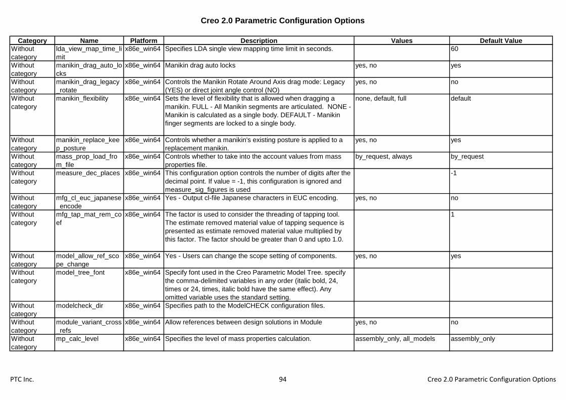
Creo 2.0 Parametric Configuration Options
Category Name Platform Description Values Default Value
Without
category
lda_view_map_time_li
mit
x86e_win64 Specifies LDA single view mapping time limit in seconds. 60
Without
category
manikin_drag_auto_lo
cks
x86e_win64 Manikin drag auto locks yes, no yes
Without
category
manikin_drag_legacy
_rotate
x86e_win64 Controls the Manikin Rotate Around Axis drag mode: Legacy
(YES) or direct joint angle control (NO)
yes, no no
Without
category
manikin_flexibility x86e_win64 Sets the level of flexibility that is allowed when dragging a
manikin. FULL - All Manikin segments are articulated. NONE -
Manikin is calculated as a single body. DEFAULT - Manikin
finger segments are locked to a single body.
none, default, full default
Without
category
manikin_replace_kee
p_posture
x86e_win64 Controls whether a manikin's existing posture is applied to a
replacement manikin.
yes, no yes
Without
category
mass_prop_load_fro
m_file
x86e_win64 Controls whether to take into the account values from mass
properties file.
by_request, always by_request
Without
category
measure_dec_places x86e_win64 This configuration option controls the number of digits after the
decimal point. If value = -1, this configuration is ignored and
measure_sig_figures is used
-1
Without
category
mfg_cl_euc_japanese
_encode
x86e_win64 Yes - Output cl-file Japanese characters in EUC encoding. yes, no no
Without
category
mfg_tap_mat_rem_co
ef
x86e_win64 The factor is used to consider the threading of tapping tool.
The estimate removed material value of tapping sequence is
presented as estimate removed material value multiplied by
this factor. The factor should be greater than 0 and upto 1.0.
1
Without
category
model_allow_ref_sco
pe_change
x86e_win64 Yes - Users can change the scope setting of components. yes, no yes
Without
category
model_tree_font x86e_win64 Specify font used in the Creo Parametric Model Tree. specify
the comma-delimited variables in any order (italic bold, 24,
times or 24, times, italic bold have the same effect). Any
omitted variable uses the standard setting.
Without
category
modelcheck_dir x86e_win64 Specifies path to the ModelCHECK configuration files.
Without
category
module_variant_cross
_refs
x86e_win64 Allow references between design solutions in Module yes, no no
Without
category
mp_calc_level x86e_win64 Specifies the level of mass properties calculation. assembly_only, all_models assembly_only
PTC Inc. 94 Creo 2.0 Parametric Configuration Options

Creo 2.0 Parametric Configuration Options
Category Name Platform Description Values Default Value
Without
category
multiple_skeletons_all
owed
x86e_win64 Allows/restricts multiple skeleton. yes, no no
Without
category
nc_jobman_visible x86e_win64 Yes - make "Submit Path" and "Abort Path" visible. No - make
"Submit Path" and "Abort Path" invisible.
yes, no no
Without
category
ncseq_outbnd_curve x86e_win64 Yes - Create out bound curve. no no
Without
category
new_ref_part_name_
disabled
x86e_win64 Disallow redirecting data sharing feature missing reference
model to a model with different name.
yes, no yes
Without
category
new_wf5_simp_rep_u
i
x86e_win64 Yes - Use Component Chooser base Simp Rep UI, No - Use
old Simp Rep definition UI.
yes, no yes
Without
category
old_style_set_datum x86e_win64 Yes - datum properties dialog has button for old-style set
datum. No - datum properties dialog does not have button for
old-style set datum.
yes, no yes
Without
category
open_builder_in_mt_
mode
x86e_win64 Open the variant builder in Model Tree Selection mode yes, no no
Without
category
orientation_style x86e_win64 Set spin orientation style to dynamic or anchored. anchored, dynamic dynamic
Without
category
output_mfg_xml x86e_win64 Allows export/import mfg model to/from xml file. Yes - make
Export/Import options visible. No - make them invisible.
yes, no no
Without
category
pattern_exact_increm
ental_dim
x86e_win64 When pattern incremental dimensions are calculated from
expressions, round them to the decimal places set by config
option default_dec_places.
yes, no no
Without
category
pdm_server_quickvie
w_rows_num
x86e_win64 Sets the default number of rows for the pdm quick view list. 7
Without
category
pipe_3d_bend_theor_i
nt_pts
x86e_win64 Yes - Displays theoretical intersections and bends in three-
dimensional models.
yes, no no
Without
category
plot_names_with_she
et
x86e_win64 Yes - Plot file names are appended with _(sheet number)
before file extension.
yes, no no
Without
category
popup_refpairintch_wi
ndow
x86e_win64 Bring forward the window being used with the reference pairing
table.
yes, no no
Without
category
prime_analysis_direct
ory
x86e_win64 Sets the default directory for the Prime files to be used for
Prime analysis calculations. Use the full pathname to avoid
problems.
Without
category
prime_automapping x86e_win64 Toggles Prime analysis automapping of variables yes, no no
PTC Inc. 95 Creo 2.0 Parametric Configuration Options

Creo 2.0 Parametric Configuration Options
Category Name Platform Description Values Default Value
Without
category
pro_design_test_mod
e_dir
x86e_win64 Sets the default directory for the Design Test mode data. If not
specified, your current working directory is the default. Use the
full pathname to avoid problems.
Without
category
propagate_by_default x86e_win64 Yes - If the modified geometry belongs to a geometry pattern, a
pattern recognition feature or a symmetry recognition feature,
the modification is automatically propagated to all
pattern/symmetry members.
yes, no no
Without
category
ptc_manikin_comforts
_path
x86e_win64 Sets the default directory for the Creo Parametric manikin
comfort angles. You must restart Creo Parametric for the
change to take effect.
Without
category
ptc_manikin_library_p
ath
x86e_win64 Sets the default directory for the Creo Parametric manikin
library (or custom manikin libraries you built containing the
proper index menu files). Use the full path name to avoid
problems. You must restart Creo Parametric for the change to
take effect.
<creo_loadpoint>\manikin_lite\
Without
category
ptc_manikin_posture_
path
x86e_win64 Sets the default directory for the Creo Parametric manikin
postures (or custom posture libraries you built). Use the full
path name to avoid problems. You must restart Creo
Parametric for the change to take effect.
Without
category
qty_balloon_change_
warning
x86e_win64 Sets the warning style when quantity balloons have changed in
a drawing. Dialog displays the warning in a dialog box,
Message displays the warning in the message area only.
dialog, message dialog
Without
category
quick_print_drawing_t
emplate
x86e_win64 Specify the path and name of a drawing template to be used by
the File > Quick Print command.
Without
category
quick_print_plotter_co
nfig_file
x86e_win64 Specify the path and name of the default plotter config file to be
used by the File > Quick Drawing command.
Without
category
radial_hole_linear_di
m
x86e_win64 YES - Option for creation of radial hole with a linear dimension
will be available.
yes, no no
Without
category
ref_scope_copy_color x86e_win64 Set the color of backed up references according to RGB
values. Enter RGB values between 0 and 100 separated by
space.
55.000000 55.000000 55.000000
Without
category
ref_scope_copy_color
_change
x86e_win64 Enable changing colors of backuped references during
selection.
yes, no yes
Without
category
ref_scope_no_pick_to
_copy
x86e_win64 Disable selecting references backuped by references control. yes, no no
Without
category
ref_scope_no_pick_to
_prohibit
x86e_win64 Disable selecting references prohibited by references control. yes, no yes
PTC Inc. 96 Creo 2.0 Parametric Configuration Options

Creo 2.0 Parametric Configuration Options
Category Name Platform Description Values Default Value
Without
category
ref_scope_prohibit_co
lor
x86e_win64 Set the color of prohibited references according to RGB values.
Enter RGB values between 0 and 100 separated by space.
45.000000 45.000000 45.000000
Without
category
ref_scope_prohibit_co
lor_change
x86e_win64 Enable changing colors of prohibited references during
selection.
yes, no yes
Without
category
regen_failure_handlin
g
x86e_win64 Specifies whether to enter resolve mode when regeneration
failures occur. Resolve_mode - Enter resolve mode when
regeneration failures occur. No_resolve_mode - Don't enter
resolve mode when regeneration failures occur.
resolve_mode,
no_resolve_mode
no_resolve_mode
Without
category
regen_int_mdls_on_r
etr
x86e_win64 Yes to regen models intersected with assem feats during
assembly retrieval.
yes, no no
Without
category
regen_solid_before_s
ave
x86e_win64 Controls whether to regenerate top model, or promot user
before regeneration if it is required
yes, no, prompt prompt
Without
category
relations_num_const_
units
x86e_win64 Specifies whether diagnostic should be issued when an
unitless numeric value causes relation expression evaluation
trouble.
yes, no no
Without
category
relations_units_sensiti
ve
x86e_win64 Set the default unit sensitivity (ignore or take into account
parameter/dimensions units) in creation of new relation data
(legacy relation data will not be unit sensitive until "converted"
to one).
yes, no yes
Without
category
remember_last_attac
h_type
x86e_win64 Yes - Sets the default of the ATTACH TYPE menu of the last
options picked.
yes, no yes
Without
category
remember_replaced_
components
x86e_win64 Set to "Yes" this option will preserve a dependency to the
replaced, outgoing, component. Set to "No" the dependency
will, when possible, be removed.
yes, no yes
Without
category
replace_comp_notes_
method
x86e_win64 Specify treatment of notes when components are replaced.
Transfer - transfer to new component. Remove - remove the
notes. Preserve - save notes in case component is restored.
transfer, remove, preserve transfer
Without
category
reroute_affected_child
ren
x86e_win64 Affected children when setting Current solution. none, auto, selective selective
Without
category
restricted_val_definiti
on
x86e_win64 Specify name and path of the file contained restricted values
definition.
Without
category
retrieve_display x86e_win64 Controls whether or not graphics data is loaded in the
background.
background, foreground background
Without
category
retrieve_merge_ref_p
arts
x86e_win64 Automatic reference parts retrieval for dependent Merge. yes, no, ignore_missing no
PTC Inc. 97 Creo 2.0 Parametric Configuration Options

Creo 2.0 Parametric Configuration Options
Category Name Platform Description Values Default Value
Without
category
round_prewf5_display
ed_dim_val
x86e_win64 Rounds the displayed value round all, round none,
calculated
calculated
Without
category
save_hidden_items_w
_status
x86e_win64 The items on the "Hidden Items" temporary layer are stored
permanently when layer display status is saved with Save
Status command.
yes, no yes
Without
category
save_view_states_me
thod
x86e_win64 Setup the method used on saving view states changes. prompt, save changes, discard
changes
prompt
Without
category
scope_invalid_refs x86e_win64 Prohibit - System will abort all attempts to create external
reference violating the scope. Backup - Warning appears.
Abort reference creation or declare as out-of-scope reference.
If you declare, backup copies to part/assembly and backup is
referenced.
copy, prohibit copy
Without
category
show_affected_childr
en_dialog
x86e_win64 Do not invoke dialog for setting Current solution. yes, no yes
Without
category
show_description_vie
w_mgr
x86e_win64 Yes - show a column for Description field for all tabs in view
manager.
yes, no no
Without
category
show_sketch_dims_in
_feature
x86e_win64 Sets the default display state of internal sketch dimensions in
the feature definition environment.
yes, no no
Without
category
simprep_column_disp
lay
x86e_win64 Controls display of Simplified Representations columns in
Model Tree, 'Automatic'-'Current Rep' column is shown
automatically when a rep is activated, 'Manual' visibility of the
column is fully controlled by user, pre-Wildfire 6 behavior.
automatic, manual automatic
Without
category
simprep_column_for
mat
x86e_win64 Specifies simplified representation model tree column format. names only, icons only, icons
and names
icons and names
Without
category
simprep_default_cnfg
_asm
x86e_win64 Retrieves a CSA model in a specified representation. Yes -
uses Open Rep dialog. No - retrieves the Master
representation. Specified Name - retrieves the model in the
specified representation name if it exists or the Default
representation.
last stored
Without
category
simprep_ondemand_
activation
x86e_win64 Enables retrieving on-demand the Master rep of an activated
model. When an assembly is activated the Assembly only rep
is retrieved.
yes, no yes
Without
category
simprep_ondemand_
cleanup
x86e_win64 Determines if a model retrieved on demand should be
removed or erased. Disabled - the model will not be removed
and will remain in the assembly. Removed - the model will be
removed. Remove_Erase - The model will be removed and
erased from memory.
disable, restore,
restore_and_erase
restore
PTC Inc. 98 Creo 2.0 Parametric Configuration Options

Creo 2.0 Parametric Configuration Options
Category Name Platform Description Values Default Value
Without
category
simprep_ondemand_
editing
x86e_win64 Enables on demand retrieval of an edited item and its parent
references. Configuration tools (Family Tables, Relations, etc)
will retrieve required models accordingly. Automatic -
Retrieves the minimum rep required to perform the operation.
automatic, master, disable,
master_with_ancestors
automatic
Without
category
simprep_ondemand_r
egeneration
x86e_win64 Enables on demand retrieval of required models during
regeneration. Can affect regeneration performance.
automatic, master, disable automatic
Without
category
single_side_surf_colo
r
x86e_win64 Allow application of color to a single side of a surface. yes, no no
Without
category
sketcher_curve_color
_synch
x86e_win64 Synchronize color assignment between sketched curves and
their sketches.
yes, no yes
Without
category
sketcher_palette_path x86e_win64 Sets the default directory for the user sketcher shape library.
Use the full path name to avoid problems.
Without
category
sketcher_strngthn_to_
def_dec_pl
x86e_win64 This option enable the user to keep a highly precise value
during creation or convertion strong dimension.
yes, no yes
Without
category
smaller_bundle_min_
bend_rad
x86e_win64 Setup whether to consider the thickness of the bundle when set
up the minimum bend radius.
yes, no no
Without
category
snap_single_constrai
nts
x86e_win64 When dynamically dragging components during component
placement, allow to snap to references one constraint at a
time.
yes, no yes
Without
category
spin_with_orientation_
center
x86e_win64 Display orientation center while reorienting. yes, no yes
Without
category
style_auto_regen_cur
ves
x86e_win64 Yes - Enable autoregeneration of curves. yes, no yes
Without
category
style_auto_regen_sha
ded_surface
x86e_win64 Yes - Enable autoregeneration of shaded surfaces. yes, no yes
Without
category
style_auto_regen_surf
ace
x86e_win64 Yes - Enable autoregeneration of surfaces. yes, no yes
Without
category
style_connection_arro
w_scale
x86e_win64 Set scale factor of surface connection arrow. Number should
be greater then 0.
1
Without
category
style_default_connecti
ons
x86e_win64 Yes - Add connections to a newly created Style surface. yes, no yes
Without
category
style_display_grid x86e_win64 Yes - Display grid for active datum plane. yes, no yes
Without
category
style_grid_spacing x86e_win64 Set the number of lines to display on the grid. Number should
be equal or greater than 2.
5
PTC Inc. 99 Creo 2.0 Parametric Configuration Options

Creo 2.0 Parametric Configuration Options
Category Name Platform Description Values Default Value
Without
category
style_state_transpare
ncy
x86e_win64 Set the value of transparency for components set to
"Transparent" in style state. Value must be between 0 and
100.
70
Without
category
style_surface_mesh_
display
x86e_win64 On - Display surfaces mesh. Off - Do not display surfaces
mesh. Off When Shaded - Display surfaces mesh except when
shaded.
off, on, off when shaded off when shaded
Without
category
style_surface_mesh_
quality
x86e_win64 Sets the quality of the surface mesh. Values range is between
0.1 to 10.
1
Without
category
template_cnfg_asm x86e_win64 Specifies the default configurable assembly template file. Use
full pathname to avoid problems.
inlbs_csa.asm
Without
category
template_esrasm x86e_win64 Specifies the designated template ESR assembly. Use full path
to avoid problems.
inlbs_asm_esr.asm
Without
category
template_layout x86e_win64 Specifies the default layout template file. Use full pathname to
avoid problems.
Without
category
tk_enable_ribbon_cus
tom_save
x86e_win64 Enable storing the Auxiliary Application User Interface
customization
yes, no no
Without
category
tool_motion_list_lengt
h
x86e_win64 Controls the number of rows visible in the tool motion list
without scrolling. This value is applied to dashboard based
NC Steps.
7
Without
category
trace_thru_splice_con
nector
x86e_win64 Report the from/to connectors of cables passing through
splices correctly.
yes, no no
Without
category
travel_bounds_display x86e_win64 Enable travel bounds display. yes, no no
Without
category
travel_bounds_transp
arency
x86e_win64 Transparency value for machine bound display. 0.8
Without
category
trngrv_roundtool_nob
ackcut
x86e_win64 Yes - Groove turning using round tool generates no back cut
motion for profile pass.
yes, no no
Without
category
upd_param_on_retr_
mark_modified
x86e_win64 Allows/disallows mark model as changed if as a result of mass
properties/relations calculation during retrieval some parameter
values are changed.
yes, no no
Without
category
use_master_for_bad_
disp_reps
x86e_win64 Yes to retrieve master rep when graphics rep has no display
data.
yes, no no
Without
category
use_strict_ui_trail x86e_win64 Perform extra validation of user interface actions when playing
back trail files.
yes, no yes
Without
category
use_web_page_font_i
n_reports
x86e_win64 Controls whether HTML reports use the browser's standard
fonts.
yes, no no
Without
category
visible_recent_files x86e_win64 Number of visible recent files. The possible range is 1 - 25. 13
PTC Inc. 100 Creo 2.0 Parametric Configuration Options

Creo 2.0 Parametric Configuration Options
Category Name Platform Description Values Default Value
Without
category
warn_if_iso_tol_missi
ng
x86e_win64 Yes - Returns the user to the dimension properties dialog to
select a different table. No - Applies the tolerance according to
existing functionality.
yes, no no
Without
category
web_enable_javascrip
t
x86e_win64 Enables or disables Pro/Web.Link in the embedded browser. off, on off
Without
category
web_max_mail_size x86e_win64 Set the maximum email attachment size in kilobytes. 5000
Without
category
weld_fillet_preference
s_file
x86e_win64 Sets the path and name of the fillet weld preferences file.
Without
category
weld_general_prefere
nces_file
x86e_win64 Sets the path and name of the general weld preferences file.
Without
category
weld_groove_prefere
nces_file
x86e_win64 Sets the path and name of the groove weld preferences file.
Without
category
weld_plug_slot_prefer
ences_file
x86e_win64 Sets the path and name of the plug/slot weld preferences file.
Without
category
weld_spot_preference
s_file
x86e_win64 Sets the path and name of the spot weld preferences file.
PTC Inc. 101 Creo 2.0 Parametric Configuration Options
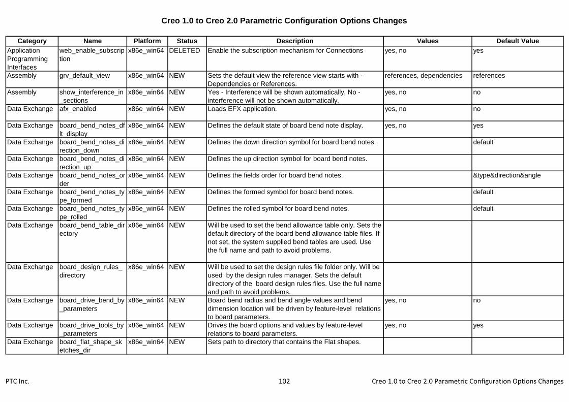
Creo 1.0 to Creo 2.0 Parametric Configuration Options Changes
Category Name Platform Status Description Values Default Value
Application
Programming
Interfaces
web_enable_subscrip
tion
x86e_win64 DELETED Enable the subscription mechanism for Connections yes, no yes
Assembly grv_default_view x86e_win64 NEW Sets the default view the reference view starts with -
Dependencies or References.
references, dependencies references
Assembly show_interference_in
_sections
x86e_win64 NEW Yes - Interference will be shown automatically, No -
interference will not be shown automatically.
yes, no no
Data Exchange afx_enabled x86e_win64 NEW Loads EFX application. yes, no no
Data Exchange board_bend_notes_df
lt_display
x86e_win64 NEW Defines the default state of board bend note display. yes, no yes
Data Exchange board_bend_notes_di
rection_down
x86e_win64 NEW Defines the down direction symbol for board bend notes. default
Data Exchange board_bend_notes_di
rection_up
x86e_win64 NEW Defines the up direction symbol for board bend notes.
Data Exchange board_bend_notes_or
der
x86e_win64 NEW Defines the fields order for board bend notes. &type&direction&angle
Data Exchange board_bend_notes_ty
pe_formed
x86e_win64 NEW Defines the formed symbol for board bend notes. default
Data Exchange board_bend_notes_ty
pe_rolled
x86e_win64 NEW Defines the rolled symbol for board bend notes. default
Data Exchange board_bend_table_dir
ectory
x86e_win64 NEW Will be used to set the bend allowance table only. Sets the
default directory of the board bend allowance table files. If
not set, the system supplied bend tables are used. Use
the full name and path to avoid problems.
Data Exchange board_design_rules_
directory
x86e_win64 NEW Will be used to set the design rules file folder only. Will be
used by the design rules manager. Sets the default
directory of the board design rules files. Use the full name
and path to avoid problems.
Data Exchange board_drive_bend_by
_parameters
x86e_win64 NEW Board bend radius and bend angle values and bend
dimension location will be driven by feature-level relations
to board parameters.
yes, no no
Data Exchange board_drive_tools_by
_parameters
x86e_win64 NEW Drives the board options and values by feature-level
relations to board parameters.
yes, no yes
Data Exchange board_flat_shape_sk
etches_dir
x86e_win64 NEW Sets path to directory that contains the Flat shapes.
PTC Inc. 102 Creo 1.0 to Creo 2.0 Parametric Configuration Options Changes

Creo 1.0 to Creo 2.0 Parametric Configuration Options Changes
Category Name Platform Status Description Values Default Value
Data Exchange board_parameters_di
rectory
x86e_win64 NEW Specifies the directory to save/retrieve board parameters
files. Use full name and path to avoid problems.
Data Exchange ecadcollab_auto_rede
f_areas
x86e_win64 NEW Automatically redefine ECAD Areas affected by
collaboration changes
yes, no yes
Data Exchange ecadcollab_auto_rede
f_comps
x86e_win64 NEW Automatically redefine components affected by
collaboration changes
yes, no yes
Data Exchange ecadcollab_auto_rede
f_holes
x86e_win64 NEW Automatically redefine holes affected by collaboration
changes
yes, no yes
Data Exchange ecadcollab_preview_l
evel
x86e_win64 NEW ECAD Collaboration preview Level full, partial, light partial
Data Exchange ecadcollab_scan_des
_on_area_chg
x86e_win64 NEW Check for affected objects resulting from ECAD Areas
collaboration changes
yes, no yes
Data Exchange ecadcollab_scan_des
_on_brd_chg
x86e_win64 NEW Check for affected objects resulting from board
collaboration changes
yes, no yes
Data Exchange ecadcollab_scan_des
_on_comp_chg
x86e_win64 NEW Check for affected objects resulting from components
collaboration changes
yes, no yes
Data Exchange ecadcollab_scan_des
_on_hole_chg
x86e_win64 NEW Check for affected objects resulting from holes
collaboration changes
yes, no yes
Data Exchange ecadcollab_supp_fail
ed_feats
x86e_win64 NEW Suppress of failed features on Object changes yes, no yes
Data Exchange ecadcollab_suppress
_cuts
x86e_win64 NEW Automatically suppress cut features in case of board
collaboration changes
yes, no yes
Data Exchange efx_enabled x86e_win64 DELETED Loads EFX application. yes, no no
Data Exchange initial_board_bend_y_
factor
x86e_win64 NEW Specifies a value used to determine the natural bend line
for a board part. This value is always used for non-
cylindrical bends. It is used for regular bends only when no
bend table is specified.
0.5
Data Exchange intf_ug_version x86e_win64 CHANGED Sets the version of Unigraphics interface. nx5, nx6, nx7 nx6, nx7, nx8 nx5 nx6
Data Exchange pro_gplug_dir x86e_win64 CHANGED Specifies the directory in which Granite application plug-
ins are located. Use the full pathname to avoid problems.
<creo1.0_loadpoint>\x86e_wi
n64\gplugs\
<creo2.0_loadpoint>\x86e_wi
n64\gplugs\
Data Exchange template_boardpart x86e_win64 NEW Specify the model to use as the default new ECAD board
template.
PTC Inc. 103 Creo 1.0 to Creo 2.0 Parametric Configuration Options Changes

Creo 1.0 to Creo 2.0 Parametric Configuration Options Changes
Category Name Platform Status Description Values Default Value
Data Exchange template_new_ecada
sm
x86e_win64 NEW Specify the model to use as the default new ECAD
assembly template.
Data
Management
dm_simple x86e_win64 NEW Activate Simple Windchill Interaction yes, no no
Drawing bom_format x86e_win64 CHANGED Sets the BOM format file to be used for a customized
BOM. Specify name and path.
<creo1.0_loadpoint>\text\for
mat.bft
<creo2.0_loadpoint>\text\for
mat.bft
Drawing drawing_setup_file x86e_win64 CHANGED Sets the default drawing setup file option values for your
Creo Parametric session, otherwise, the system uses the
default drawing setup file option values. Certain
parameters in the file are valid only if you have a license
for Pro/DETAIL.
<creo1.0_loadpoint>\text\pro
detail.dtl
<creo2.0_loadpoint>\text\pro
detail.dtl
Drawing drawing_warn_if_flex
_feature
x86e_win64 NEW Display a warning dialog upon opening a drawing with
models that contain flexible features advising users that
annotations may be out of date and should be verified.
yes, no yes
Drawing preferred_export_for
mat
x86e_win64 CHANGED Set the preferred export format for Drawings and Layouts.
Set the default preferred export file type for export from
drawings.
cgm, tiff, iges, dxf, step, pdf,
dwg, medusa, stheno
Drawing pro_palette_dir x86e_win64 CHANGED Sets the default directory for drawing symbol palette files. <creo1.0_loadpoint>\symbols
\palette\
<creo2.0_loadpoint>\symbols
\palette\
Electromechanic
al
cabling_split_multi_pn
t_locs
x86e_win64 NEW Setup whether to convert multiple-location features into
single location features.
yes, no yes
Electromechanic
al
display_duplicate_har
ness_msg
x86e_win64 NEW Display warning message when duplicate harness are
identified in the same assembly.
yes, no yes
Environment save_section_surface
s
x86e_win64 NEW Yes - Save section surfaces with models. No - Do not
save section surfaces with models.
yes, no yes
File Storage &
Retrieval
pro_font_dir x86e_win64 CHANGED Sets the default font directory (Creo Parametric will load
all fonts in this directory into the drawing regardless of the
contents of the system and working directories).
<creo1.0_loadpoint>\text\font
s\
<creo2.0_loadpoint>\text\font
s\
File Storage &
Retrieval
pro_surface_finish_di
r
x86e_win64 CHANGED Sets the default directory for your user-defined surface
finish symbols. Use the full pathname to avoid problems.
<creo1.0_loadpoint>\symbols
\surffins\
<creo2.0_loadpoint>\symbols
\surffins\
PTC Inc. 104 Creo 1.0 to Creo 2.0 Parametric Configuration Options Changes

Creo 1.0 to Creo 2.0 Parametric Configuration Options Changes
Category Name Platform Status Description Values Default Value
File Storage &
Retrieval
set_model_types_to_
save
x86e_win64 CHANGED Determines which model types are used in the Save
Changed command. The format is a list of extensions
separated by spaces.
asm prt drw sec mfg gph ipf
asm prt drw sec mfg gph ipf
cem
File Storage &
Retrieval
template_module x86e_win64 NEW Specifies the default module template file. Use full
pathname to avoid problems.
inlbs_asm_module.asm
Manufacturing ncmdl_bar_stock_par
t_path
x86e_win64 CHANGED Sets path for storage and retrieval of stock instances for
creating workpiece in NC Model. Specify full path,
including part name, to avoid problems.
<creo1.0_loadpoint>\text\ncm
dl_data\ncmdl_bar.prt
<creo2.0_loadpoint>\text\ncm
dl_data\ncmdl_bar.prt
Manufacturing ncmdl_billet_stock_p
art_path
x86e_win64 CHANGED Sets path for storage and retrieval of stock instances for
creating workpiece in NC Model. Specify full path,
including part name, to avoid problems.
<creo1.0_loadpoint>\text\ncm
dl_data\ncmdl_billet.prt
<creo2.0_loadpoint>\text\ncm
dl_data\ncmdl_billet.prt
Manufacturing
Without
category
dm_nc_process x86e_win64 CHANGED Sets output of NC process information as content on the
NC Assembly CAD Document in XML Format. Yes -
Outputs the file whenever CAD Document is Saved. No -
Does not output the file.
yes, no no
Model Display animate_component_
placement
x86e_win64 NEW Animate the transition between component states in
placement.
yes, no yes
Model Display blended_transparenc
y
x86e_win64 CHANGED Yes - Transparent colors will appear using alpha blending
(if supported) when the model is shaded.
yes, no yes, no, independent yes
Model Display datum_point_symbol x86e_win64 CHANGED Specifies the shape of datum point symbols displayed in
Part or Assembly mode.
cross, circle, triangle, square
dot
cross
Model Display model_detail_options
_file
x86e_win64 CHANGED Sets the path to the file which contains the default model
detail option values for new models.
<creo1.0_loadpoint>\text\3d_i
nch.dtl
<creo2.0_loadpoint>\text\3d_i
nch.dtl
Photorender default_scene_filena
me
x86e_win64 CHANGED Complete path to the scene file to be used as default
scene file.
<creo1.0_loadpoint>\graphic-
library\scenes\/creo_default_
scene.scn
<creo2.0_loadpoint>\graphic-
library\scenes\/creo_default_
scene.scn
PTC Inc. 105 Creo 1.0 to Creo 2.0 Parametric Configuration Options Changes
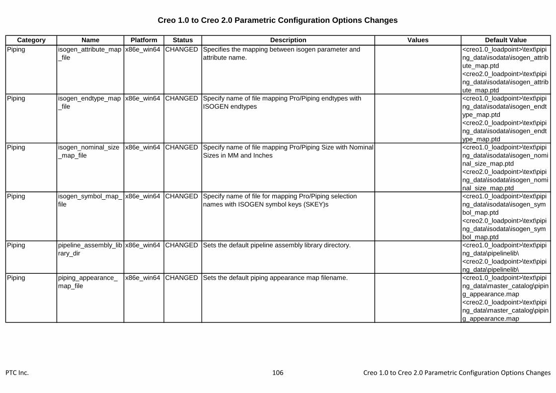
Creo 1.0 to Creo 2.0 Parametric Configuration Options Changes
Category Name Platform Status Description Values Default Value
Piping isogen_attribute_map
_file
x86e_win64 CHANGED Specifies the mapping between isogen parameter and
attribute name.
<creo1.0_loadpoint>\text\pipi
ng_data\isodata\isogen_attrib
ute_map.ptd
<creo2.0_loadpoint>\text\pipi
ng_data\isodata\isogen_attrib
ute_map.ptd
Piping isogen_endtype_map
_file
x86e_win64 CHANGED Specify name of file mapping Pro/Piping endtypes with
ISOGEN endtypes
<creo1.0_loadpoint>\text\pipi
ng_data\isodata\isogen_endt
ype_map.ptd
<creo2.0_loadpoint>\text\pipi
ng_data\isodata\isogen_endt
ype_map.ptd
Piping isogen_nominal_size
_map_file
x86e_win64 CHANGED Specify name of file mapping Pro/Piping Size with Nominal
Sizes in MM and Inches
<creo1.0_loadpoint>\text\pipi
ng_data\isodata\isogen_nomi
nal_size_map.ptd
<creo2.0_loadpoint>\text\pipi
ng_data\isodata\isogen_nomi
nal_size_map.ptd
Piping isogen_symbol_map_
file
x86e_win64 CHANGED Specify name of file for mapping Pro/Piping selection
names with ISOGEN symbol keys (SKEY)s
<creo1.0_loadpoint>\text\pipi
ng_data\isodata\isogen_sym
bol_map.ptd
<creo2.0_loadpoint>\text\pipi
ng_data\isodata\isogen_sym
bol_map.ptd
Piping pipeline_assembly_lib
rary_dir
x86e_win64 CHANGED Sets the default pipeline assembly library directory. <creo1.0_loadpoint>\text\pipi
ng_data\pipelinelib\
<creo2.0_loadpoint>\text\pipi
ng_data\pipelinelib\
Piping piping_appearance_
map_file
x86e_win64 CHANGED Sets the default piping appearance map filename. <creo1.0_loadpoint>\text\pipi
ng_data\master_catalog\pipin
g_appearance.map
<creo2.0_loadpoint>\text\pipi
ng_data\master_catalog\pipin
g_appearance.map
PTC Inc. 106 Creo 1.0 to Creo 2.0 Parametric Configuration Options Changes

Creo 1.0 to Creo 2.0 Parametric Configuration Options Changes
Category Name Platform Status Description Values Default Value
Piping piping_bolt_nut_selec
t_file
x86e_win64 CHANGED Piping bolts and nuts selection file. <creo1.0_loadpoint>\text\pipi
ng_data\master_catalog\pipin
g_bolt_nut_select.ptd
<creo2.0_loadpoint>\text\pipi
ng_data\master_catalog\pipin
g_bolt_nut_select.ptd
Piping piping_end_compatibi
lity_file
x86e_win64 CHANGED Sets the default piping end compatibility filename. <creo1.0_loadpoint>\text\pipi
ng_data\master_catalog\pipin
g_end_compatibility.ptd
<creo2.0_loadpoint>\text\pipi
ng_data\master_catalog\pipin
g_end_compatibility.ptd
Piping piping_fitt_category_
map_file
x86e_win64 CHANGED Sets the default piping fitting category map filename. <creo1.0_loadpoint>\text\pipi
ng_data\sample_project\pipin
g_fitt_category_map.ptd
<creo2.0_loadpoint>\text\pipi
ng_data\sample_project\pipin
g_fitt_category_map.ptd
Piping piping_fitt_library_dir x86e_win64 CHANGED Sets the default piping fitting library directory. <creo1.0_loadpoint>\text\pipi
ng_data\fittinglib\
<creo2.0_loadpoint>\text\pipi
ng_data\fittinglib\
Piping piping_insulation_dir_
file
x86e_win64 CHANGED Sets the default piping insulation directory filename. <creo1.0_loadpoint>\text\pipi
ng_data\sample_project\pipin
g_insulation_dir.ptd
<creo2.0_loadpoint>\text\pipi
ng_data\sample_project\pipin
g_insulation_dir.ptd
Piping piping_manufacture_
dir_file
x86e_win64 CHANGED Sets the default piping manufacture directory filename. <creo1.0_loadpoint>\text\pipi
ng_data\master_catalog\pipin
g_manufacture_dir.ptd
<creo2.0_loadpoint>\text\pipi
ng_data\master_catalog\pipin
g_manufacture_dir.ptd
PTC Inc. 107 Creo 1.0 to Creo 2.0 Parametric Configuration Options Changes

Creo 1.0 to Creo 2.0 Parametric Configuration Options Changes
Category Name Platform Status Description Values Default Value
Piping piping_material_file x86e_win64 CHANGED Sets the default piping material filename. <creo1.0_loadpoint>\text\pipi
ng_data\master_catalog\pipin
g_material.ptd
<creo2.0_loadpoint>\text\pipi
ng_data\master_catalog\pipin
g_material.ptd
Piping piping_mcat_dir x86e_win64 CHANGED Sets the default piping master catalog directory. <creo1.0_loadpoint>\text\pipi
ng_data\master_catalog\
<creo2.0_loadpoint>\text\pipi
ng_data\master_catalog\
Piping piping_mcat_dir_file x86e_win64 CHANGED Sets the default piping master catalog directory filename. <creo1.0_loadpoint>\text\pipi
ng_data\master_catalog\pipin
g_mcat_dir.ptd
<creo2.0_loadpoint>\text\pipi
ng_data\master_catalog\pipin
g_mcat_dir.ptd
Piping piping_project_data_d
ir
x86e_win64 CHANGED Sets the default Project data directory. <creo1.0_loadpoint>\text\pipi
ng_data\sample_project\
<creo2.0_loadpoint>\text\pipi
ng_data\sample_project\
Piping piping_spec_dir_file x86e_win64 CHANGED Sets the default piping specification directory filename. <creo1.0_loadpoint>\text\pipi
ng_data\sample_project\pipin
g_spec_dir.ptd
<creo2.0_loadpoint>\text\pipi
ng_data\sample_project\pipin
g_spec_dir.ptd
Piping units_system_dic_file x86e_win64 CHANGED Specifies the file containing the mapping for MCAT
filename and units.
<creo1.0_loadpoint>\text\pipi
ng_data\master_catalog\pipin
g_units_system_dic_file.ptd
<creo2.0_loadpoint>\text\pipi
ng_data\master_catalog\pipin
g_units_system_dic_file.ptd
PTC Inc. 108 Creo 1.0 to Creo 2.0 Parametric Configuration Options Changes

Creo 1.0 to Creo 2.0 Parametric Configuration Options Changes
Category Name Platform Status Description Values Default Value
Printing &
Plotting
plot_carberry_extend
s
x86e_win64 CHANGED When plotting to a raster format (jpg, tiff, etc), setting this
option to YES will ignore the view border and produce
output sized to the smallest rectangle that includes the
drawing items. When plotting to a raster format (jpg, tiff,
etc), set to YES to ignore the view border and produce
output sized to the smallest rectangle that includes the
drawing items.
yes, no no
Sheetmetal material_upd_smt_be
nd_table
x86e_win64 CHANGED Defines whether assignment of material to the model via
Pro/Toolkit will overwrite existing bend table data and y
factor value. Always Replace - Overwrites existing data.
Never Replace - Keeps existing data Defines whether
assignment of material to the model via Creo Toolkit will
overwrite existing bend table data and y factor value.
Always Replace - Overwrites existing data. Never Replace
- Keeps existing data
always_replace,
never_replace
always_replace
Sheetmetal smt_bend_notes_dflt
_display
x86e_win64 CHANGED Define the default state of Bend Note display (sheetmetal
Mode) Define the default state of bend note display
(sheetmetal mode)
yes, no yes
Sheetmetal smt_bend_notes_dire
ction_down
x86e_win64 CHANGED Define the Down Direction symbol for Bend Notes
(sheetmetal Mode) Define the down direction symbol for
bend notes (sheetmetal mode)
default
Sheetmetal smt_bend_notes_dire
ction_up
x86e_win64 CHANGED Define the Up Direction symbol for Bend Notes
(sheetmetal Mode) Define the up direction symbol for
bend notes (sheetmetal mode)
default
Sheetmetal smt_bend_notes_ord
er
x86e_win64 CHANGED Define the Fields Order for Bend Notes (sheetmetal Mode)
Define the fields order for bend notes (sheetmetal mode)
&type&direction&angle
Sheetmetal smt_bend_notes_type
_formed
x86e_win64 CHANGED Define the Formed symbol for Bend Notes (sheetmetal
Mode) Define the formed symbol for bend notes
(sheetmetal mode)
default
Sheetmetal smt_bend_notes_type
_rolled
x86e_win64 CHANGED Define the Rolled symbol for Bend Notes (sheetmetal
Mode) Define the rolled symbol for bend notes
(sheetmetal mode)
default
System auto_traceback x86e_win64 CHANGED When set to yes, traceback.log file will be generated when
fatal error occurs. "always": a traceback file will be
generated when a fatal error occurs. "yes", "ask": ask the
user whether to generate a traceback. "no", "never": no
traceback will be generated.
yes, no, never, ask, always no always
PTC Inc. 109 Creo 1.0 to Creo 2.0 Parametric Configuration Options Changes

Creo 1.0 to Creo 2.0 Parametric Configuration Options Changes
Category Name Platform Status Description Values Default Value
System web_browser_homep
age
x86e_win64 CHANGED Enter location of Creo Parametric browser home page. <creo1.0_loadpoint>\help\usa
scii\resource_center_index.ht
ml
<creo2.0_loadpoint>\help\usa
scii\resource_center_index.ht
ml
User Interface
Without
category
enable_learning_conn
ector
x86e_win64 CHANGED Enable the Learning Connector, which provides context
specific access to videos, training, help topics, and
technical support content. When enabled, the Learning
Connector is added to the ribbon bar next to Help.
yes, no yes
Without
category
assemble_module_in
_rep
x86e_win64 NEW Retrieves the assembled module to CSA in a specified
representation.
representative module variant
Without
category
auto_eval_current_cn
fg_rule
x86e_win64 NEW If the option is "yes" simplified representation would be
updated each time on retrieve/regeneration if it contains
current configuration rule.
yes, no yes
Without
category
constraint_reference_
redefine
x86e_win64 CHANGED keep_constraint_type - Adjusts the component position
to keep the same constraint type. reset_constraint_type -
Automatically changes the constraint type to keep the
position of the component.
keep_constraint_type,
reset_constraint_type
keep_constraint_type
Without
category
data_sharing_gen_no
tification
x86e_win64 DELETED off, on off
Without
category
default_comp_modul
e_geom_scope
x86e_win64 NEW Set the specified Shared Geometry reference control
conditions to newly added components for configurable
structure.
all, none, pg, tagged tagged
Without
category
default_obj_module_c
onstr_scope
x86e_win64 NEW Set the specified Shared Placement reference control
conditions to newly created models for configurable
structure if template models were not used.
all, none, interfaces, tagged tagged
Without
category
default_obj_module_
geom_scope
x86e_win64 NEW Set the specified Shared Geometry reference control
conditions to newly created models for configurable
structure modules if template models were not used.
all, none, pg, tagged all
Without
category
default_ref_current_m
odule_vrnt
x86e_win64 NEW Allow references to current design solution only. yes, no yes
PTC Inc. 110 Creo 1.0 to Creo 2.0 Parametric Configuration Options Changes

Creo 1.0 to Creo 2.0 Parametric Configuration Options Changes
Category Name Platform Status Description Values Default Value
Without
category
depthcue_always x86e_win64 DELETED Depth cue aids in visualizing a wireframe model. With
depth cue enabled, wireframe lines become darker as
they extend into the screen and lighter as they extend
towards the screen. Depth cue is supported only by the
appropriate graphics hardware.
yes, no yes
Without
category
depthcue_value x86e_win64 DELETED Aids in visualizing a wireframe model. With depth cue
enabled, this option specifies the default percentage of
depthcue used. Depth cue is supported only by the
appropriate graphics hardware.
Without
category
display_combined_vie
ws
x86e_win64 NEW Display combined view tabs by default yes, no no
Without
category
display_images x86e_win64 NEW Display images outside of Style feature yes, no yes
Without
category
dm_enable_impex_at
tributes
x86e_win64 NEW yes, no no
Without
category
edge_tess_quality x86e_win64 NEW Set the accuracy level for arc tessllation. high, medium, low low
Without
category
enable_fsaa x86e_win64 NEW Enable OpenGL full screen anti-aliasing. off, 2, 4, 8, 16, 32 off
Without
category
enable_obsoleted_fea
tures
x86e_win64 NEW yes, no no
Without
category
enable_sociallink x86e_win64 NEW Allow Windchill SocialLink to connect with Creo
Parametric. When enabled SocialLink commands will be
added to the Application Menu and the Ribbon bar. Enter
"Yes" to enable SocialLink, and "No" to disable it
yes, no yes
Without
category
intf3d_out_catia_v5_v
ersion
x86e_win64 CHANGED Allows the user to switch between the default and
alternate converter version for export to CATIA V5
16, 17, 18, 19, 20 16, 17, 18,
19, 20, 21, 22
16
Without
category
layout_guides x86e_win64 CHANGED Yes - shows all guides; No - hides all guides
Enable/Disable layout guides.
yes, no yes
Without
category
lda_prefix_in_basic_d
im_box
x86e_win64 NEW Add prefix to basic box while converting the dimension to
basic.
yes, no no
Without
category
manikin_drag_legacy
_rotate
x86e_win64 CHANGED controls whether to rotate around axis manikin drag mode
invokes the old rotate version (or the forward kinematics
new version Controls the Manikin Rotate Around Axis
drag mode: Legacy (YES) or direct joint angle control (NO)
yes, no no
PTC Inc. 111 Creo 1.0 to Creo 2.0 Parametric Configuration Options Changes

Creo 1.0 to Creo 2.0 Parametric Configuration Options Changes
Category Name Platform Status Description Values Default Value
Without
category
mfg_cl_euc_japanese
_encode
x86e_win64 NEW Yes - Output cl-file Japanese characters in EUC encoding. yes, no no
Without
category
module_variant_cross
_refs
x86e_win64 NEW Allow references between design solutions in Module yes, no no
Without
category
open_builder_in_mt_
mode
x86e_win64 NEW Open the variant builder in Model Tree Selection mode yes, no no
Without
category
ptc_manikin_comforts
_path
x86e_win64 NEW Sets the default directory for the Creo Parametric manikin
comfort angles. You must restart Creo Parametric for the
change to take effect.
Without
category
ptc_manikin_library_p
ath
x86e_win64 CHANGED Sets the default directory for the Creo Parametric manikin
library (or custom manikin libraries you built containing the
proper index menu files). Use the full path name to avoid
problems. You must restart Creo Parametric for the
change to take effect.
<creo1.0_loadpoint>\manikin
_lite\
<creo2.0_loadpoint>\manikin
_lite\
Without
category
quick_print_plotter_co
nfig_file
x86e_win64 CHANGED Specify the path and name of the default plotter config file
to be used by the File > Quick Print command. Specify
the path and name of the default plotter config file to be
used by the File > Quick Drawing command.
Without
category
reroute_affected_chil
dren
x86e_win64 NEW Affected children when setting Current solution. none, auto, selective selective
Without
category
show_affected_childr
en_dialog
x86e_win64 NEW Do not invoke dialog for setting Current solution. yes, no yes
Without
category
simprep_default_cnfg
_asm
x86e_win64 NEW Retrieves a CSA model in a specified representation. Yes -
uses Open Rep dialog. No - retrieves the Master
representation. Specified Name - retrieves the model in
the specified representation name if it exists or the Default
representation.
last stored
Without
category
single_side_surf_colo
r
x86e_win64 NEW Allow application of color to a single side of a surface. yes, no no
Without
category
template_cnfg_asm x86e_win64 NEW Specifies the default configurable assembly template file.
Use full pathname to avoid problems.
inlbs_csa.asm
Without
category
template_config_asm x86e_win64 DELETED Specifies the default configurable assembly template file.
Use full pathname to avoid problems.
Without
category
template_container x86e_win64 DELETED Specifies the default container template file. Use full
pathname to avoid problems.
PTC Inc. 112 Creo 1.0 to Creo 2.0 Parametric Configuration Options Changes

Creo 1.0 to Creo 2.0 Parametric Configuration Options Changes
Category Name Platform Status Description Values Default Value
Without
category
tool_motion_list_lengt
h
x86e_win64 NEW Controls the number of rows visible in the tool motion list
without scrolling. This value is applied to dashboard
based NC Steps.
7
Without
category
tracesketch x86e_win64 DELETED Display images outside of Style feature yes, no yes
PTC Inc. 113 Creo 1.0 to Creo 2.0 Parametric Configuration Options Changes

Creo 2.0 Simulate Configuration Options
Category Name Platform Description Values Default Value
Application
Programming
Interfaces
add_java_class_path x86e_win64 Prepends the option value on the java environment variable,
CLASSPATH, used to find classes in J-Link programs. To
specify multiple search paths in the same line, delimit them
using ':' on UNIX, and ';' on Windows NT.
Application
Programming
Interfaces
enable_protk_xml_sch
ema
x86e_win64 Enables XML-Schema validation for Pro/TK feature XMLs yes, no no
Application
Programming
Interfaces
jlink_java2 x86e_win64 Option to force use of Java-2 JRE command line ("java"
instead of "jre")
off, on on
Application
Programming
Interfaces
prodevdat x86e_win64 Specify the full path to an additional Toolkit registry file.
Application
Programming
Interfaces
protkdat x86e_win64 Specify the full path to an additional Toolkit registry file.
Application
Programming
Interfaces
toolkit_registry_file x86e_win64 Specify the full path to an additional Toolkit registry file.
Application
Programming
Interfaces
web_disable_js_comm
and
x86e_win64 Enter a specific javascript command to be disabled
Application
Programming
Interfaces
web_link_file_read x86e_win64 Sets Pro/Web.Link permission to read data from the local file
system.
yes, no no
Application
Programming
Interfaces
web_link_file_write x86e_win64 Sets Pro/Web.Link permission to write data to the local file
system.
yes, no no
Application
Programming
Interfaces
web_link_proe_read x86e_win64 Sets Pro/Web.Link permission to read data from a Creo
Parametric session.
yes, no no
Application
Programming
Interfaces
web_link_proe_write x86e_win64 Sets Pro/Web.Link permission to modify data in a Creo
Parametric session.
yes, no no
Application
Programming
Interfaces
web_link_security_auto
prompt
x86e_win64 Yes - The Security dialog box is displayed when a
Pro/Web.Link function requires security access beyond the
current settings.
yes, no yes
PTC Inc. 114 Creo 2.0 Simulate Configuration Options
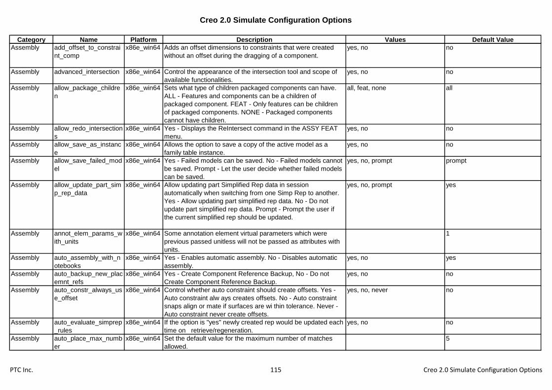
Creo 2.0 Simulate Configuration Options
Category Name Platform Description Values Default Value
Assembly add_offset_to_constrai
nt_comp
x86e_win64 Adds an offset dimensions to constraints that were created
without an offset during the dragging of a component.
yes, no no
Assembly advanced_intersection x86e_win64 Control the appearance of the intersection tool and scope of
available functionalities.
yes, no no
Assembly allow_package_childre
n
x86e_win64 Sets what type of children packaged components can have.
ALL - Features and components can be a children of
packaged component. FEAT - Only features can be children
of packaged components. NONE - Packaged components
cannot have children.
all, feat, none all
Assembly allow_redo_intersection
s
x86e_win64 Yes - Displays the ReIntersect command in the ASSY FEAT
menu.
yes, no no
Assembly allow_save_as_instanc
e
x86e_win64 Allows the option to save a copy of the active model as a
family table instance.
yes, no no
Assembly allow_save_failed_mod
el
x86e_win64 Yes - Failed models can be saved. No - Failed models cannot
be saved. Prompt - Let the user decide whether failed models
can be saved.
yes, no, prompt prompt
Assembly allow_update_part_sim
p_rep_data
x86e_win64 Allow updating part Simplified Rep data in session
automatically when switching from one Simp Rep to another.
Yes - Allow updating part simplified rep data. No - Do not
update part simplified rep data. Prompt - Prompt the user if
the current simplified rep should be updated.
yes, no, prompt yes
Assembly annot_elem_params_w
ith_units
x86e_win64 Some annotation element virtual parameters which were
previous passed unitless will not be passed as attributes with
units.
1
Assembly auto_assembly_with_n
otebooks
x86e_win64 Yes - Enables automatic assembly. No - Disables automatic
assembly.
yes, no yes
Assembly auto_backup_new_plac
emnt_refs
x86e_win64 Yes - Create Component Reference Backup, No - Do not
Create Component Reference Backup.
yes, no no
Assembly auto_constr_always_us
e_offset
x86e_win64 Control whether auto constraint should create offsets. Yes -
Auto constraint alw ays creates offsets. No - Auto constraint
snaps align or mate if surfaces are wi thin tolerance. Never -
Auto constraint never create offsets.
yes, no, never no
Assembly auto_evaluate_simprep
_rules
x86e_win64 If the option is "yes" newly created rep would be updated each
time on retrieve/regeneration.
yes, no no
Assembly auto_place_max_numb
er
x86e_win64 Set the default value for the maximum number of matches
allowed.
5
PTC Inc. 115 Creo 2.0 Simulate Configuration Options

Creo 2.0 Simulate Configuration Options
Category Name Platform Description Values Default Value
Assembly auto_update_intersecte
d_models
x86e_win64 Control the appearance of the intersection tool and scope of
available functionalities.
yes, no yes
Assembly autoplace_single_comp x86e_win64 Assembling components with an interface will automatically
place the component at the first position satisfying the
interface definitions.
yes, no yes
Assembly bump_revnum_on_retr
_regen
x86e_win64 Determines whether or not revision number is increased for
generic models that regenerate and change during assembly
retrieval. Only applies if new_asm_regen_revnums is yes
(otherwise, there will be no revision number bumping).
yes, no yes
Assembly can_snap_to_missing_
ref
x86e_win64 Controls whether to enable snapping to missing references
while dragging components for placement. Yes - Snapping is
enabled while dragging. No - Snapping is disabled while
dragging.
yes, no yes
Assembly check_interface_criteri
a
x86e_win64 Check for interfaces when placing a component. yes, no no
Assembly check_interference_of_
matches
x86e_win64 Show only matches that do not interfere with other
components.
yes, no yes
Assembly check_same_assy_part
s
x86e_win64 Determines whether to permit different names for different
part occurrences, or not in mirror subassembly UI.
yes, no yes
Assembly chooser_size_filter_def
ault
x86e_win64 Sets the size filter default value as a percentage of the overall
assembly size
Assembly comp_angle_offset_ep
s
x86e_win64 Specifies the angle epsilon such that if the desired surfaces
are equal or greater than the epsilon (in degrees), than an
angle offset constraint will be created.
10
Assembly comp_assemble_start x86e_win64 Sets the initial assembly placement behavior when
assembling a new component. Default - Default initial position.
Package - Define initial position using the Move option.
Constraint_in_Window - Use secondary window.
Move_then_Place - Define initial position using the Move
option and then define placement constraints.
package, constrain_in_window,
default, move_then_place
Assembly comp_placement_assu
mptions
x86e_win64 Use placement assumptions when placing components. yes, no yes
Assembly comp_retr_angular_inc
rement
x86e_win64 Sets the accuracy for the selection of external components
based on graphic computation.
1
Assembly comp_rollback_on_red
ef
x86e_win64 No - Assembly is not rolled back when the user redefines a
component.
yes, no yes
PTC Inc. 116 Creo 2.0 Simulate Configuration Options

Creo 2.0 Simulate Configuration Options
Category Name Platform Description Values Default Value
Assembly copy_geom_update_pr
e_2000i_dep
x86e_win64 Yes - Flags independent copy geom features in a pre-2000i
model as modified when retrieved into Creo Parametric. Save
the model immediately to update the model's copy geom
dependency information.
yes, no
Assembly copy_geometry_metho
d
x86e_win64 Sets the default copy geometry reference(s) type publish_geometry, references publish_geometry
Assembly create_temp_interfaces x86e_win64 Allow the automatic creation of interfaces based on previous
assembly instructions.
yes, no no
Assembly dim_inactive_compone
nts
x86e_win64 Display inactive assembly components with stippled
transparency and default color (grey). Default value is
shade_only.
never, always, shaded_only shaded_only
Assembly disp_regen_success_m
sg
x86e_win64 Issue successfull regeneration messages for assembly
models.
yes, no no
Assembly enable_advance_collisi
on
x86e_win64 Enables advance collision settings usage. yes, no no
Assembly enable_assembly_accu
racy
x86e_win64 No - Disables accuracy modification for assembly objects. yes, no yes
Assembly enable_implied_joints x86e_win64 Allow underconstrained components as mechanism
connections.
yes, no yes
Assembly erv_show_external_onl
y
x86e_win64 Yes - Global Reference Viewer will show objects with external
references only; No - all the objects will be visible
yes, no no
Assembly fail_ref_copy_when_mi
ssing_orig
x86e_win64 Yes - When using a copied geom feature or a backed-up
external reference with the Design Manager, and the
reference is missing in the original, then the copied geom
feature fails. No - The feature freezes and does not update.
yes, no yes
Assembly fix_refs_to_intersection
s
x86e_win64 Sets remnant removal ability for the ReIntersect command in
the ASSY FEAT menu. Yes - You can remove remnants. No -
You cannot remove remnants.
yes, no no
Assembly force_upd_assem_mp_
in_simp_rep
x86e_win64 Update mass properties parameters even when some of the
components of the assembly are not in master rep.
yes, no, use_stored use_stored
Assembly freeze_failed_assy_co
mp
x86e_win64 No - Requires an action to fix the assembly or freeze the
component that fails retrieval. Yes - Freezes any component
failing retrieval at its last known assembly location. Missing
refs using offsets or internal datums do not cause
components to freeze.
yes, no no
PTC Inc. 117 Creo 2.0 Simulate Configuration Options

Creo 2.0 Simulate Configuration Options
Category Name Platform Description Values Default Value
Assembly grv_default_view x86e_win64 Sets the default view the reference view starts with -
Dependencies or References.
references, dependencies references
Assembly ignore_non_displayed_i
tems
x86e_win64 Ignores nondisplayed items when searching the component
interface during component placement.
yes, no no
Assembly include_sub_model_int
erfaces
x86e_win64 Includes sub model interfaces as possible references for
interface to interface component placement.
yes, no yes
Assembly interface_criteria_mism
atch
x86e_win64 FAIL_PLACEMENT - Fail regeneration upon component
interface criteria mismatch. WARNING_ONLY - A warning
message is given during regeneration for the criteria
mismatch only without failure. IGNORE - Interface criteria
mismatch ignored during regeneration.
ignore, warning_only,
fail_placement
warning_only
Assembly modify_offset_during_c
omp_drag
x86e_win64 Enables the modification of the value of offset dimensions
during component dragging.
yes, no no
Assembly mp_dens_ft_column_m
trl_assigned
x86e_win64 Yes - Allows adding an MP_DENSITY column in FT when a
material is assigned to a model. When set may cause the
same material to have different values for the Density
parameter in different instances. Does not affect legacy
models.
yes, no no
Assembly mtrl_convert_units x86e_win64 If set to "Yes" Creo Parametric will automatically convert units
in materials from a library to the model system of units.
yes, no yes
Assembly package_constraints x86e_win64 Action to take for packaged components in Assembly mode.
Update - Updates components if assembly changes. Freeze -
Does not move components if assembly changes. Disallow -
Does not allow packaged components in assembly (must be
fully constrained).
disallow, freeze, update update
Assembly package_ref_alert x86e_win64 Control whether alert dialog is given when packaged
component is referenced. Yes - Allow alert when a packaged
component is referenced. No - No Alert is given when a
packaged component is referenced.
yes, no no
Assembly preserve_comp_color_i
n_preview
x86e_win64 Yes - During component placement, component being
assembled will retain its normal colors. No - During
component placement, component being assembled is shown
in preview color.
yes, no no
Assembly regen_notebook_w_as
sem
x86e_win64 Specifies whether or not the notebook will be automatically
regenerated upon assembly regeneration.
yes, no yes
Assembly replace_comp_name_
method
x86e_win64 Sets the naming convention used when replacing
components.
transfer, remove, preserve transfer
PTC Inc. 118 Creo 2.0 Simulate Configuration Options

Creo 2.0 Simulate Configuration Options
Category Name Platform Description Values Default Value
Assembly replace_history_rule_or
der
x86e_win64 Set the default order of the history evaluation rule in the
replace operation. Disable - the evaluation rule will be disabled
by default. Number - set the order of the rule relative to other
evaluation rules.
1, 3, 2, disable, 4, 5 3
Assembly replace_interface_rule_
order
x86e_win64 Set the default order of the interface evaluation rule in the
replace operation. Disable - the evaluation rule will be disabled
by default. Number - set the order of the rule relative to other
evaluation rules.
1, 3, 2, disable, 4, 5 1
Assembly replace_sameid_rule_o
rder
x86e_win64 Set the default order of the same id evaluation rule in the
replace operation. Disable - the evaluation rule will be disabled
by default. Number - set the order of the rule relative to other
evaluation rules.
1, 3, 2, disable, 4, 5 5
Assembly replace_samename_rul
e_order
x86e_win64 Set the default order of the same name evaluation rule in the
replace operation. Disable - the evaluation rule will be disabled
by default. Number - set the order of the rule relative to other
evaluation rules.
1, 3, 2, disable, 4, 5 2
Assembly replace_sameparam_r
ule_order
x86e_win64 Set the default order of the same parameters evaluation rule
in the replace operation. Disable - the evaluation rule will be
disabled by default. Number - set the order of the rule relative
to other evaluation rules.
1, 3, 2, disable, 4, 5 4
Assembly replace_unrelated_auto
matic
x86e_win64 Availability of automatic reference pairing in unrelated replace.
No - Automatic reference pairing is not available. Yes -
Automatic reference pairing is available.
yes, no no
Assembly retrieve_instance_depe
ndencies
x86e_win64 Determines whether to retrieve the dependencies of the
generic when an instance is retrieved.
instance_deps_only,
instance_and_generic_deps,
instance_req_generic
instance_req_generic
Assembly rv_current_object x86e_win64 Will control default option when setting a model or component
as the current object.
model, component, component +
model
component + model
Assembly rv_search_scope x86e_win64 Sets the search scope for children when entering the
reference viewer. Session - Search all objects in session.
Window - Search objects in the active window only.
session, window session
Assembly search_area_for_comp
_interfaces
x86e_win64 Defines the search area for the component interface as a
percentage of the component size during component
placement.
100
Assembly search_not_retrieved_
models
x86e_win64 Expands search to include models that have not been
retrieved into session. If Yes, models will be brought into
session possibly causing performance issues.
yes, no yes
PTC Inc. 119 Creo 2.0 Simulate Configuration Options

Creo 2.0 Simulate Configuration Options
Category Name Platform Description Values Default Value
Assembly sel_insts_on_comp_ret
rieval
x86e_win64 Yes - If the components used in the assembly instances are
themselves generics, the systems asks if you want to choose
an instance as each component is retrieved. No - The generic
model of the component is retrieved automatically.
yes, no no
Assembly show_interference_in_s
ections
x86e_win64 Yes - Interference will be shown automatically, No -
interference will not be shown automatically.
yes, no no
Assembly shrinkwrap_alert x86e_win64 Displays the Shrinkwrap alert the first time the quality level is
increased.
yes, no yes
Assembly simprep_default_model
_status
x86e_win64 Determines the default model status while defining a new
simplified rep.
master, geometry, exclude,
graphics, light graphics rep
exclude
Assembly simprep_ondemand_se
lection
x86e_win64 Determines the rep to be retrieved when selecting a
reference. Automatic Retrieves the minimum rep required to
perform the operation.
automatic, master, disable automatic
Assembly simprep_ondemand_se
ttings
x86e_win64 Determines on-demand retrieval behavior in simplified
representation views. Prompt - Ask for confirmation before
retrieving on-demand. Never_prompt - Retrieve models on-
demand automatically with no confirmation. Disabled - on
demand is disabled.
prompt, disable, never_prompt never_prompt
Assembly skeleton_model_defaul
t_color
x86e_win64 Specifies the color Creo Parametric uses to display new
skeleton models. The three decimal values ranging from 0
through 100 specify (in order) the percentages of red, green,
and blue in the resulting color. For example, 0 0 49 specifies
medium blue.
0.000000 75.000000
100.000000
Assembly snap_to_constraints_d
uring_drag
x86e_win64 Enables the dynamic snapping to constraints during the
dragging of components.
yes, no yes
Assembly update_copy_geom_lo
cation
x86e_win64 Yes-Copy Geometry will try to update location of copied
geometry based on changes to component placements even if
some components are excluded or in graphics rep.
yes, no yes
Assembly update_rep_refs x86e_win64 "Yes" updates top assembly simplified reps for replacements
during regeneration and upon replacement.
yes, no yes
Assembly use_3d_thumbnail_in_l
wg_rep
x86e_win64 Control the usage of 3D thumbnails when retrieving in light
weight graphic representation
yes, no yes
Assembly use_active_model_in_tr
ansform
x86e_win64 Transform analysis default behavior: use active model CSYS
and units or not.
yes, no no
Assembly
Process
curr_proc_comp_def_c
olor
x86e_win64 Specifies the default color used to display the current
component in a process assembly.
0.000000 0.000000 0.000000
PTC Inc. 120 Creo 2.0 Simulate Configuration Options

Creo 2.0 Simulate Configuration Options
Category Name Platform Description Values Default Value
Assembly
Process
curr_proc_comp_def_f
ont
x86e_win64 Specifies the default font used on the current component in a
process assembly.
Assembly
Process
display_comps_to_ass
emble
x86e_win64 Yes - The design model goes into memory and displays. Pick
process components from the design model or the Model
Tree. No - Only the Model Tree displays. As you pick process
components from the Model Tree, they go into memory.
yes, no yes
Assembly
Process
offset_line_def_color x86e_win64 Specifies the color that offset lines are displayed in drawings. 0.000000 0.000000 0.000000
Assembly
Process
offset_line_def_font x86e_win64 Specifies the font in which offset lines are displayed in
drawings.
Assembly
Process
prev_proc_comp_def_c
olor
x86e_win64 Specify the default color for components added to a process
assembly in a previous step.
0.000000 0.000000 0.000000
Assembly
Process
prev_proc_comp_def_f
ont
x86e_win64 Specify the default font for previously added components in a
process assembly.
Casting &
Mold Design
allow_shrink_dim_befor
e
x86e_win64 Allow calculation before relations. yes, no no
Casting &
Mold Design
default_mold_base_ve
ndor
x86e_win64 Default Value for Mold Base vendor. futaba_mm, dme, hasco,
dme_mm, hasco_mm
Casting &
Mold Design
default_shrink_formula x86e_win64 Default option of shrinkage formula: 1/(1-S) - ASME standard
or 1+S (simple).
asme, simple simple
Casting &
Mold Design
mold_layout_origin_na
me
x86e_win64 Sets a specified coordinate system as the default for the
cavity layout origin.
Casting &
Mold Design
mold_vol_surf_no_auto
_rollback
x86e_win64 Do not perform automatic rollback while modifying mold
volumes or parting surfaces.
yes, no no
Casting &
Mold Design
pro_catalog_dir x86e_win64 Sets the path to the catalog directory containing the catalog
menu and the names of other catalog files, such as ejector
pins. For example: pro_catalog_dir
proe_loadpoint/apps_data/mold_data/catalog. Use full path
name to avoid problems.
Casting &
Mold Design
pro_cav_lay_rule_dir x86e_win64 Sets the default directory for cavity layout rules. Use the full
path name to avoid problems.
Casting &
Mold Design
shrinkage_value_displa
y
x86e_win64 Determines how dimensions are displayed when shrinkage is
applied to a model with Pro/MOLDESIGN. Percent_shrink -
Dimensions appear with the shrinkage percent.
final_value, percent_shrink percent_shrink
Colors color x86e_win64 Turns the colors on or off. Turning colors off displays the
model wireframe in white.
yes, no yes
PTC Inc. 121 Creo 2.0 Simulate Configuration Options

Creo 2.0 Simulate Configuration Options
Category Name Platform Description Values Default Value
Colors color_ramp_size x86e_win64 Specifies the number of shades in a color ramp. Applicable to
multi-color, shaded model displays of simulation / analysis
results. System graphics must support 256 colors and color
maps that compress.
-1
Colors color_resolution x86e_win64 Specifies minimum allowable deviation between user-defined
colors. Colors having RGB values within tolerance of existing
colors cannot be created. Decreasing this setting allows more
colors that are very similar in RGB value to be defined.
0.1
Colors color_windows x86e_win64 All_windows - Wireframe colors display in the main window
and all auxiliary windows. One_window - Colors display only in
the main window. Auxiliary windows display wireframe in the
default color.
all_windows, one_window all_windows
Colors global_appearance_file x86e_win64 Material Global Appearance file path.
Colors mat_assign_appearanc
e
x86e_win64 Control whether default appearance in material definition is
automatically assigned to a part.
yes, no yes
Colors number_user_colors x86e_win64 Specifies the maximum number of different wireframe colors
that can display in the graphics area(s) at any given moment.
-1
Colors pro_colormap_path x86e_win64 Specifies the directory path for a color map (.map) file to be
loaded from disk. Use the full path name to avoid problems.
Colors suppress_appearance_
message
x86e_win64 Suppress the Lightworks appearance conversion notification
dialog.
yes, no no
Colors system_background_c
olor
x86e_win64 Defines default graphics area background color. The three
decimal values specify (in order) percentage of red, green and
blue in the resulting color. For example, 0 0 49 specifies a
medium blue. Change in session using View>Display
Settings>System Colors.
0.000000 0.000000 0.000000
Colors system_colors_file x86e_win64 Specifies the system color file. Use the full path name to avoid
problems.
Colors system_curves_color x86e_win64 Defines default curve color. The three decimal values specify
(in order) percentage of red, green and blue in the resulting
color. For example, 0 0 49 specifies a medium blue. Change
in session using View>Display Settings>System Colors.
0.000000 0.000000 0.000000
PTC Inc. 122 Creo 2.0 Simulate Configuration Options
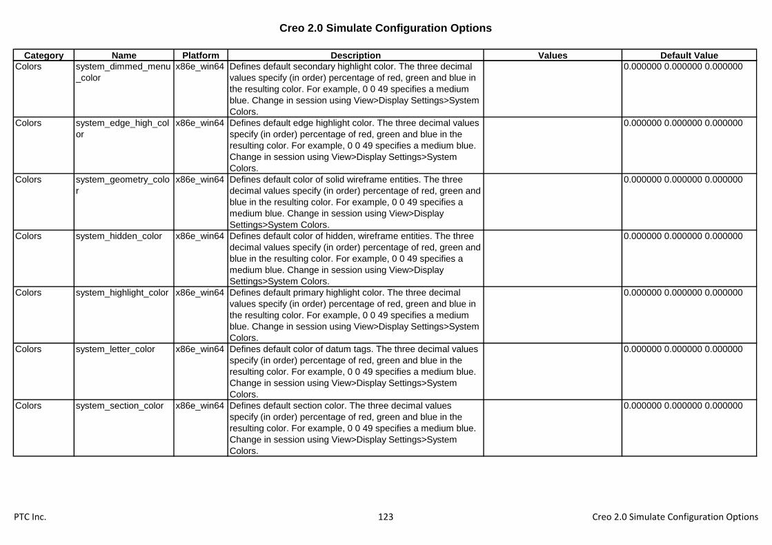
Creo 2.0 Simulate Configuration Options
Category Name Platform Description Values Default Value
Colors system_dimmed_menu
_color
x86e_win64 Defines default secondary highlight color. The three decimal
values specify (in order) percentage of red, green and blue in
the resulting color. For example, 0 0 49 specifies a medium
blue. Change in session using View>Display Settings>System
Colors.
0.000000 0.000000 0.000000
Colors system_edge_high_col
or
x86e_win64 Defines default edge highlight color. The three decimal values
specify (in order) percentage of red, green and blue in the
resulting color. For example, 0 0 49 specifies a medium blue.
Change in session using View>Display Settings>System
Colors.
0.000000 0.000000 0.000000
Colors system_geometry_colo
r
x86e_win64 Defines default color of solid wireframe entities. The three
decimal values specify (in order) percentage of red, green and
blue in the resulting color. For example, 0 0 49 specifies a
medium blue. Change in session using View>Display
Settings>System Colors.
0.000000 0.000000 0.000000
Colors system_hidden_color x86e_win64 Defines default color of hidden, wireframe entities. The three
decimal values specify (in order) percentage of red, green and
blue in the resulting color. For example, 0 0 49 specifies a
medium blue. Change in session using View>Display
Settings>System Colors.
0.000000 0.000000 0.000000
Colors system_highlight_color x86e_win64 Defines default primary highlight color. The three decimal
values specify (in order) percentage of red, green and blue in
the resulting color. For example, 0 0 49 specifies a medium
blue. Change in session using View>Display Settings>System
Colors.
0.000000 0.000000 0.000000
Colors system_letter_color x86e_win64 Defines default color of datum tags. The three decimal values
specify (in order) percentage of red, green and blue in the
resulting color. For example, 0 0 49 specifies a medium blue.
Change in session using View>Display Settings>System
Colors.
0.000000 0.000000 0.000000
Colors system_section_color x86e_win64 Defines default section color. The three decimal values
specify (in order) percentage of red, green and blue in the
resulting color. For example, 0 0 49 specifies a medium blue.
Change in session using View>Display Settings>System
Colors.
0.000000 0.000000 0.000000
PTC Inc. 123 Creo 2.0 Simulate Configuration Options
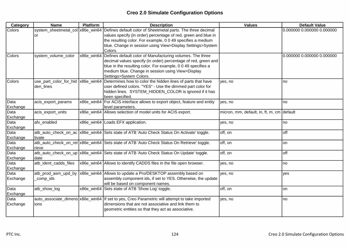
Creo 2.0 Simulate Configuration Options
Category Name Platform Description Values Default Value
Colors system_sheetmetal_col
or
x86e_win64 Defines default color of Sheetmetal parts. The three decimal
values specify (in order) percentage of red, green and blue in
the resulting color. For example, 0 0 49 specifies a medium
blue. Change in session using View>Display Settings>System
Colors.
0.000000 0.000000 0.000000
Colors system_volume_color x86e_win64 Defines default color of Manufacturing volumes. The three
decimal values specify (in order) percentage of red, green and
blue in the resulting color. For example, 0 0 49 specifies a
medium blue. Change in session using View>Display
Settings>System Colors.
0.000000 0.000000 0.000000
Colors use_part_color_for_hid
den_lines
x86e_win64 Determines how to color the hidden lines of parts that have
user defined colors. "YES" - Use the dimmed part color for
hidden lines. SYSTEM_HIDDEN_COLOR is ignored if it has
been specified.
yes, no no
Data
Exchange
acis_export_params x86e_win64 For ACIS interface allows to export object, feature and entity
level parameters.
yes, no no
Data
Exchange
acis_export_units x86e_win64 Allows selection of model units for ACIS export. micron, mm, default, in, ft, m, cm default
Data
Exchange
afx_enabled x86e_win64 Loads EFX application. yes, no no
Data
Exchange
atb_auto_check_on_ac
tivate
x86e_win64 Sets state of ATB 'Auto Check Status On Activate' toggle. off, on off
Data
Exchange
atb_auto_check_on_ret
rieve
x86e_win64 Sets state of ATB 'Auto Check Status On Retrieve' toggle. off, on on
Data
Exchange
atb_auto_check_on_up
date
x86e_win64 Sets state of ATB 'Auto Check Status On Update' toggle. off, on off
Data
Exchange
atb_ident_cadds_files x86e_win64 Allows to identify CADDS files in the file open browser. yes, no no
Data
Exchange
atb_prod_asm_upd_by
_comp_ids
x86e_win64 Allows to update a Pro/DESKTOP assembly based on
assembly component ids, if set to YES. Otherwise, the update
will be based on component names.
yes, no yes
Data
Exchange
atb_show_log x86e_win64 Sets state of ATB 'Show Log' toggle. off, on on
Data
Exchange
auto_associate_dimens
ions
x86e_win64 If set to yes, Creo Parametric will attempt to take imported
dimensions that are not associative and link them to
geometric entities so that they act as associative.
yes, no no
PTC Inc. 124 Creo 2.0 Simulate Configuration Options

Creo 2.0 Simulate Configuration Options
Category Name Platform Description Values Default Value
Data
Exchange
board_bend_notes_dflt
_display
x86e_win64 Defines the default state of board bend note display. yes, no yes
Data
Exchange
board_bend_notes_dire
ction_down
x86e_win64 Defines the down direction symbol for board bend notes. default
Data
Exchange
board_bend_notes_dire
ction_up
x86e_win64 Defines the up direction symbol for board bend notes.
Data
Exchange
board_bend_notes_ord
er
x86e_win64 Defines the fields order for board bend notes. &type&direction&angle
Data
Exchange
board_bend_notes_typ
e_formed
x86e_win64 Defines the formed symbol for board bend notes. default
Data
Exchange
board_bend_notes_typ
e_rolled
x86e_win64 Defines the rolled symbol for board bend notes. default
Data
Exchange
board_bend_table_dire
ctory
x86e_win64 Will be used to set the bend allowance table only. Sets the
default directory of the board bend allowance table files. If not
set, the system supplied bend tables are used. Use the full
name and path to avoid problems.
Data
Exchange
board_design_rules_dir
ectory
x86e_win64 Will be used to set the design rules file folder only. Will be
used by the design rules manager. Sets the default directory
of the board design rules files. Use the full name and path to
avoid problems.
Data
Exchange
board_drive_bend_by_
parameters
x86e_win64 Board bend radius and bend angle values and bend
dimension location will be driven by feature-level relations to
board parameters.
yes, no no
Data
Exchange
board_drive_tools_by_
parameters
x86e_win64 Drives the board options and values by feature-level relations
to board parameters.
yes, no yes
Data
Exchange
board_flat_shape_sket
ches_dir
x86e_win64 Sets path to directory that contains the Flat shapes.
Data
Exchange
board_parameters_dire
ctory
x86e_win64 Specifies the directory to save/retrieve board parameters files.
Use full name and path to avoid problems.
Data
Exchange
cadds_import_layer x86e_win64 Allows import of CADDS5 layering. yes, no yes
Data
Exchange
catia_out_to_existing_
model
x86e_win64 Append - If the selected CATIA model already exists, the new
data is appended to the existing CATIA file. Overwrite - If the
selected CATIA model already exists, the newly exported file
overwrites the existing one.
append, overwrite append
Data
Exchange
cgm_use_pentable x86e_win64 No - Do not use a defined pen table for formatting of CGM
export.
yes, no no
PTC Inc. 125 Creo 2.0 Simulate Configuration Options

Creo 2.0 Simulate Configuration Options
Category Name Platform Description Values Default Value
Data
Exchange
cri_grafting_enable x86e_win64 Activates "Graft features" button under File menu. This allows
user to graft features created in CRI model to active model.
yes, no no
Data
Exchange
dazix_default_placeme
nt_unit
x86e_win64 Specifies the units to be used for data imported in Dazix files. micron, mm, thou
Data
Exchange
dazix_export_mounthol
e
x86e_win64 Yes - Causes the MOUNTHOLE section of a Dazix file to be
processed as a mount hole. No - Causes the MOUNTHOLE
section to be processed as a cut.
yes, no no
Data
Exchange
dazix_z_translation x86e_win64 Yes - Passes the objects in the .edn files through z translation. yes, no yes
Data
Exchange
direct_vrml x86e_win64 Yes - Enables direct VRML conversion. yes, no no
Data
Exchange
dwg_export_format x86e_win64 Provides the ability to choose DWG file version when
exporting from Creo Parametric drawing.
14, 2000, 2004, 2007, 2010 2007
Data
Exchange
dxf_block_to_pro_sym
bol
x86e_win64 Specifies whether or not DXF BLOCKS to be imported as
Creo Parametric symbols. Yes - Imports BLOCKS as symbol
definitions, No - Imports BLOCKS as separate entities.
yes, no no
Data
Exchange
dxf_export_format x86e_win64 Provides the ability to choose DXF file version when exporting
from Creo Parametric drawing.
12, 13, 14, 2000, 2004, 2007,
2010
2007
Data
Exchange
dxf_in_faceted_brep x86e_win64 Default, faceted boundary representation is allowed in import. yes, no yes
Data
Exchange
dxf_in_proxy_entity x86e_win64 Controls the input support for ACAD_PROXY_ENTITY. yes, no yes
Data
Exchange
dxf_out_comments x86e_win64 YES - comments (999 group codes) will be created in DXF file
exported from Creo Parametric. NO - DXF file will be created
without comment lines.
yes, no yes
Data
Exchange
dxf_out_drawing_scale x86e_win64 Specify whether or not to export drawing scale to the DXF or
DWG file. Yes - Includes a scale factor DIMLFAC in the
exported DXF/DWG. No - Exports without using a scale for
the drawing. Set to Yes when exporting to read into AutoCAD.
yes, no no
Data
Exchange
dxf_out_scale_views x86e_win64 Specify whether or not to scale drawing views when exporting
to the DXF or DWG file. Yes - rescales the entire drawing in
such a way that the main view scale becomes 1:1. No -
exports without rescaling.
yes, no no
PTC Inc. 126 Creo 2.0 Simulate Configuration Options

Creo 2.0 Simulate Configuration Options
Category Name Platform Description Values Default Value
Data
Exchange
dxf_out_sep_dim_w_br
eaks
x86e_win64 YES - Breaks dimensions with breaks on witness lines to
separate entities and preserves the original picture. No -
Exports such dimensions as DXF DIMENSION entities and
removes the breaks on witness lines.
yes, no no
Data
Exchange
dxfio_in_sjis x86e_win64 Determines if the SJIS is supported when importing/exporting
DXF files in Japanese
yes, no yes
Data
Exchange
ecad_area_default_imp
ort
x86e_win64 Defines how imported ECAD areas are treated. Cosm_area -
Treats imported ECAD areas as cosmetic area features.
3d_volume - Imports ECAD areas with Z-heights as a 3D
enclosed quilt.
3d_volume, cosm_area cosm_area
Data
Exchange
ecad_board_csys_def_
name
x86e_win64 Specifies the default coordinate system name added to an
ECAD board being imported. If you do not set this variable,
the system prompts you for a name.
Data
Exchange
ecad_comp_csys_def_
name
x86e_win64 Specifies the default coordinate system name added to an
ECAD component being imported. If you do not set this
variable, the system prompts you for a name.
Data
Exchange
ecad_comp_layer_map x86e_win64 Allow layer mapping for ECAD component's import into
Assembly.
yes, no yes
Data
Exchange
ecad_comp_naming_c
onvention
x86e_win64 ECAD_NAME / ECAD_ALT_NAME - Uses the components
package name or part number as the part name.
ECAD_NAME_ECAD_ALT_NAME - Concatenates the
component's package name and part number as the part
name.
ecad_name,
ecad_name_ecad_alt_name,
ecad_alt_name
ecad_name
Data
Exchange
ecad_comp_xsec_def_
name
x86e_win64 Will allow pre-setting default X-section to be used for
component outline output to *.eda format.
Data
Exchange
ecad_create_hint_add x86e_win64 Assists in creation of an ecad_hint.map file. Yes -
Automatically renames components, if necessary, each time
library of component outlines is imported to Creo Parametric.
This does not create an ecad_hint.map file. It controls if
ecad_hint.add is created.
yes, no yes
Data
Exchange
ecad_default_comp_he
ight
x86e_win64 Sets default value and units for an ECAD component being
imported. Units can be: inch, mil (1E-3 inches), thou (1E-6
inches), cm, mm, micron (1E-6 meters), dsu (1E-8 meters). If
not set, the system uses the current component's units.
-1.000000 ecad_unit_not_set
Data
Exchange
ecad_default_comp_pl
ace_status
x86e_win64 Sets default component placement status for export
(parameter setting will override the default).
unplaced, fixed, placed, mcad,
ecad
placed
PTC Inc. 127 Creo 2.0 Simulate Configuration Options

Creo 2.0 Simulate Configuration Options
Category Name Platform Description Values Default Value
Data
Exchange
ecad_edmd_out_versio
n
x86e_win64 Set the EDMD output version. 2.0, 1.2 2
Data
Exchange
ecad_exp_both_two_ar
eas
x86e_win64 Supports the export of ECAD areas with different "Above
Board" and "Below Board" conditions. "yes" - Enables you to
export both sided keep-in/keep-out ECAD areas as two
individual areas (top and bottom).
yes, no no
Data
Exchange
ecad_export_cuts_as_
holes
x86e_win64 Exports Creo Parametric cuts as holes to ECAD systems. yes, no yes
Data
Exchange
ecad_export_holes_as
_cuts
x86e_win64 Exports Creo Parametric holes as cuts to ECAD systems. yes, no no
Data
Exchange
ecad_import_holes_as
_features
x86e_win64 Import sections specified as DRILLED_HOLE as through-all
holes. Boards created with Creo Parametric drilled holes
export with default value of NPTH for the ECAD_HOLE_TYPE
parameter. Create this feature parameter if a value of PTH is
needed (IDF 2.0/3.0).
yes, no yes
Data
Exchange
ecad_import_relative_a
ccuracy
x86e_win64 Defines the relative accuracy used in ECAD import. 0.0012
Data
Exchange
ecad_mapping_file x86e_win64 Specify the ecad_hint.map file that will be used for ECAD
operations.
Data
Exchange
ecad_missing_compon
ent_status
x86e_win64 Setup default status for missing components in "Investigate
Placement" Dialog.
keep_missing, delete_missing keep_missing
Data
Exchange
ecad_mtg_hole_import x86e_win64 Setup the default for the import of ECAD Holes type MTG (IDF
3.0 or IDX ONLY)
yes, no, as lightweight yes
Data
Exchange
ecad_other_outl_csys_
def_name
x86e_win64 Specifies the default coordinate system name for the
.OTHER_OUTLINE section of an IDF 2.0 ECAD component
being imported. If you do not set this variable, the system uses
ECAD DEFAULT as coordinate system name.
Data
Exchange
ecad_panel_csys_def_
name
x86e_win64 Specifies the default coordinate system name added to an
ECAD panel being imported. If you do not set this variable, the
system prompts you for a name.
Data
Exchange
ecad_pin_hole_import x86e_win64 Set up the default for the import of ECAD Holes from type PIN
(IDF 3.0 or IDX ONLY)
yes, no, as lightweight no
Data
Exchange
ecad_reject_strategy x86e_win64 Configures the way the changes are rejected. ui_based, as_original, as_base ui_based
Data
Exchange
ecad_set_intercomm_c
ompatible
x86e_win64 Yes - Set both EDA format version and output method to
support InterComm product, yes or no.
yes, no no
PTC Inc. 128 Creo 2.0 Simulate Configuration Options

Creo 2.0 Simulate Configuration Options
Category Name Platform Description Values Default Value
Data
Exchange
ecad_tool_hole_import x86e_win64 Setup the default for the import of ECAD Holes type TOOL
(IDF 3.0 or IDX ONLY)
yes, no, as lightweight yes
Data
Exchange
ecad_via_hole_import x86e_win64 Set up the default for the import of ECAD Holes from type VIA
(IDF 3.0 or IDX ONLY)
yes, no, as lightweight yes
Data
Exchange
ecadcollab_auto_redef
_areas
x86e_win64 Automatically redefine ECAD Areas affected by collaboration
changes
yes, no yes
Data
Exchange
ecadcollab_auto_redef
_comps
x86e_win64 Automatically redefine components affected by collaboration
changes
yes, no yes
Data
Exchange
ecadcollab_auto_redef
_holes
x86e_win64 Automatically redefine holes affected by collaboration changes yes, no yes
Data
Exchange
ecadcollab_preview_le
vel
x86e_win64 ECAD Collaboration preview Level full, partial, light partial
Data
Exchange
ecadcollab_scan_des_
on_area_chg
x86e_win64 Check for affected objects resulting from ECAD Areas
collaboration changes
yes, no yes
Data
Exchange
ecadcollab_scan_des_
on_brd_chg
x86e_win64 Check for affected objects resulting from board collaboration
changes
yes, no yes
Data
Exchange
ecadcollab_scan_des_
on_comp_chg
x86e_win64 Check for affected objects resulting from components
collaboration changes
yes, no yes
Data
Exchange
ecadcollab_scan_des_
on_hole_chg
x86e_win64 Check for affected objects resulting from holes collaboration
changes
yes, no yes
Data
Exchange
ecadcollab_supp_failed
_feats
x86e_win64 Suppress of failed features on Object changes yes, no yes
Data
Exchange
ecadcollab_suppress_c
uts
x86e_win64 Automatically suppress cut features in case of board
collaboration changes
yes, no yes
Data
Exchange
enable_acis_export_ext
ension
x86e_win64 Enable ACIS export extension. yes, no no
Data
Exchange
enable_cadra_export x86e_win64 Enables the CADRA command in the EXPORT menu. This
enables the creation of a CADRA specific IGES file.
yes, no no
Data
Exchange
explode_iges_dimensio
n_note
x86e_win64 Controls how dimensions are treated when importing an IGES
drawing file. Yes - Each IGES dimension explodes into an
independent note with the dimension text and a dimension
with an empty note. No - Dimensions are treated as before.
yes, no no
Data
Exchange
export_3d_force_defaul
t_naming
x86e_win64 Specify whether the Creo Parametric model names should be
used for STEP export. Yes - Use default naming. No - Add
suffixes to model file names.
yes, no no
Data
Exchange
export_to_shipit x86e_win64 Enable Ship-it interface export. yes, no no
PTC Inc. 129 Creo 2.0 Simulate Configuration Options
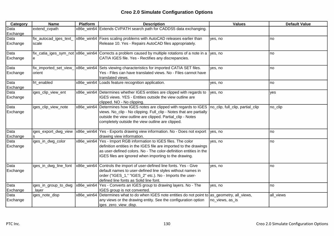
Creo 2.0 Simulate Configuration Options
Category Name Platform Description Values Default Value
Data
Exchange
extend_cvpath x86e_win64 Extends CVPATH search path for CADDS5 data exchanging.
Data
Exchange
fix_autocad_iges_text_
scale
x86e_win64 Fixes scaling problems with AutoCAD releases earlier than
Release 10. Yes - Repairs AutoCAD files appropriately.
yes, no no
Data
Exchange
fix_catia_iges_sym_not
e
x86e_win64 Corrects a problem caused by multiple rotations of a note in a
CATIA IGES file. Yes - Rectifies any discrepancies.
yes, no no
Data
Exchange
fix_imported_set_view_
orient
x86e_win64 Sets viewing characteristics for imported CATIA SET files.
Yes - Files can have translated views. No - Files cannot have
translated views.
yes, no no
Data
Exchange
frt_enabled x86e_win64 Loads feature recognition application. yes, no no
Data
Exchange
iges_clip_view_ent x86e_win64 Determines whether IGES entities are clipped with regards to
IGES views. YES - Entities outside the view outline are
clipped. NO - No clipping.
yes, no yes
Data
Exchange
iges_clip_view_note x86e_win64 Determines how IGES notes are clipped with regards to IGES
views. No_clip - No clipping. Full_clip - Notes that are partially
outside the view outline are clipped. Partial_clip - Notes
completely outside the view outline are clipped.
no_clip, full_clip, partial_clip no_clip
Data
Exchange
iges_export_dwg_view
s
x86e_win64 Yes - Exports drawing view information. No - Does not export
drawing view information.
yes, no no
Data
Exchange
iges_in_dwg_color x86e_win64 Yes - Import RGB information to IGES files. The color
definition entities in the IGES file are imported to the drawings
as user-defined colors. No - The color-definition entities in the
IGES files are ignored when importing to the drawing.
yes, no no
Data
Exchange
iges_in_dwg_line_font x86e_win64 Controls the import of user-defined line fonts. Yes - Give
default names to user-defined line styles without names in
order ("IGES_1," "IGES_2" etc.). No - Imports the user-
defined line fonts as Solid line font.
yes, no no
Data
Exchange
iges_in_group_to_dwg
_layer
x86e_win64 Yes - Converts an IGES group to drawing layers. No - The
IGES group is not converted.
yes, no no
Data
Exchange
iges_note_disp x86e_win64 Determines what to do when IGES note entities do not point to
any views or the drawing entity. See the configuration option
iges_zero_view_disp.
as_geometry, all_views,
no_views, as_is
all_views
PTC Inc. 130 Creo 2.0 Simulate Configuration Options

Creo 2.0 Simulate Configuration Options
Category Name Platform Description Values Default Value
Data
Exchange
iges_out_all_srfs_as x86e_win64 Default - Outputs all surfaces as appropriate IGES surfaces.
114 - This option applies only to representations of surface
shape. Trimmed surface entities (type 144) are exported
regardless of setting. 128 - Outputs all surfaces as IGES B-
spline surfaces.
128, 114, default default
Data
Exchange
iges_out_assembly_def
ault_mode
x86e_win64 Set default for assembly export via IGES. Flat - Single level
model. One_level - Assy structure with pointers to
components. All_levels - Assy structure with all comps to
IGES files. All_parts - Assy to IGES files with geom info of
comps and assy feats.
flat, one_level, all_levels,
all_parts
flat
Data
Exchange
iges_out_catia_gdt_wid
th
x86e_win64 Yes - Enables the desired width of a gtol symbol to be
exported to CATIA.
yes, no no
Data
Exchange
iges_out_catia_notes x86e_win64 Yes - Breaks a large note (greater than 70 strings) down into
smaller notes, each producing an IGES entity.
yes, no no
Data
Exchange
iges_out_dwg_color x86e_win64 Yes - Enables the export of RGB information to IGES files.
The user-defined colors in the drawing are exported to an
IGES file as color definition entities. No - Ignores the user-
defined colors in the drawing when exporting IGES file.
yes, no no
Data
Exchange
iges_out_dwg_line_font x86e_win64 Controls the export of user-defined line font through IGES. No -
Exports all geometry as solid font.
yes, no no
Data
Exchange
iges_out_ent_as_bsplin
e
x86e_win64 True - Exports all geometry entities, other than lines or arcs,
as third-degree B-splines. False - Does not export entities as
third-degree B-splines.
true, false FALSE
Data
Exchange
iges_out_jamais_compl
iant
x86e_win64 Yes - Specifies IGES output with special JAMA-IS subset
specification, compliant with the version 1.02 of JAMA-IS
(Japan Automobile Manufacturers Association IGES Subset
Specification). No - Specifies normal IGES.
yes, no no
Data
Exchange
iges_out_mil_d_28000 x86e_win64 Yes - Specifies IGES output that uses the MIL-D-28000 entity
subset.
yes, no no
Data
Exchange
iges_out_spl_crvs_as_
126
x86e_win64 Converts all part geometry spline curves to IGES entity 126 (B-
spline) when creating an IGES file.
yes, no yes
Data
Exchange
iges_out_spl_srfs_as_1
28
x86e_win64 Converts all part geometry spline surfaces to IGES entity 128
(B-spline) when creating an IGES file.
yes, no yes
Data
Exchange
iges_out_start_note x86e_win64 Yes - Exports the text specified by system_iges_header_file
and user_iges_header_file as a note on the drawing. To
control note placement, use the configuration file option
put_iges_drawing_entity.
yes, no no
PTC Inc. 131 Creo 2.0 Simulate Configuration Options

Creo 2.0 Simulate Configuration Options
Category Name Platform Description Values Default Value
Data
Exchange
iges_out_symbol_entity x86e_win64 Exports a drawing symbol as an IGES general symbol entity,
IGES type number 228 (yes), or as its component entities:
notes and lines.
yes, no yes
Data
Exchange
iges_out_trim_curve_d
eviation
x86e_win64 Sets the maximum value for the distance between an XYZ
trimming curve (boundary) and the underlying surface of a
trimmed surface
-1
Data
Exchange
iges_out_trim_xyz x86e_win64 Controls whether or not XYZ data is output in addition to UV
data for trimmed surfaces.
yes, no yes
Data
Exchange
iges_out_trm_srfs_as_
143
x86e_win64 Yes - Exports all surfaces to IGES entities 141 and 143. This
overrides option iges_out_trm_xyz.
yes, no no
Data
Exchange
iges_zero_view_disp x86e_win64 When IGES geometry does not point to any views or the
drawing entity. All_views - Creates a copy of the entity for
each view. No_views - Does not create the entity at all. As_is -
Creates the entity once, using only its own transformation
information.
all_views, no_views, as_is all_views
Data
Exchange
initial_board_bend_y_fa
ctor
x86e_win64 Specifies a value used to determine the natural bend line for a
board part. This value is always used for non-cylindrical
bends. It is used for regular bends only when no bend table is
specified.
0.5
Data
Exchange
interface_quality x86e_win64 Sets amount of checking for overlapping lines and collecting
lines of same pen color before exporting plot or 2-D file. 0 - No
check or collection. 1 - No check, but collection. 2 - Partial
check and collection. 3 - Complete check and collection.
3
Data
Exchange
intf_cadds_import_mak
e_solid
x86e_win64 Allows the user to solidify all closed quilts during import
CADDS5 model.
yes, no no
Data
Exchange
intf_cadds_version x86e_win64 Allows the user to switch between the default and alternate
converter version for interface with CADDS5
14, 15 14
Data
Exchange
intf_generate_log_file x86e_win64 Specifies not to generate or generate short or long log files for
data exchange import operations.
no, long, short short
Data
Exchange
intf_in_dwg_pnt_ent x86e_win64 Yes - Converts an IGES or DXF point entity to a drawing point. yes, no no
Data
Exchange
intf_in_dwg_view x86e_win64 Controls if associativity in an imported IGES view is
preserved. 3D_VIEWS - tries to create 3D views if 3D model
exists in the file. 2D_VIEWS - Imported IGES views work as
2D. No - Imported IGES views are exploded and become
unrelated.
no, 2d_views, 3d_views 2d_views
PTC Inc. 132 Creo 2.0 Simulate Configuration Options

Creo 2.0 Simulate Configuration Options
Category Name Platform Description Values Default Value
Data
Exchange
intf_in_extract_profiles x86e_win64 Default, no profiles in a data exchange file will be extracted for
use.
all, none, comp none
Data
Exchange
intf_in_granite_direct_e
nable
x86e_win64 Allows the user to switch back to the old 'Import Feature'
method of reading Desktop .des files and Granite .g files into
Creo Parametric. By default, Creo Parametric directly opens
these models.
yes, no yes
Data
Exchange
intf_in_layer_asm_dialo
g
x86e_win64 Yes - Presents a dialog box to control the import of both layers
and assemblies. You can choose from the list of layers and/or
solids available in the file to select one or more for import.
yes, no no
Data
Exchange
intf_in_profile_default x86e_win64 Specifies the name of the existing import profile to use by
default.
Data
Exchange
intf_out_as_bezier x86e_win64 Exports all B-splines as Bezier surfaces. yes, no no
Data
Exchange
intf_out_asm_mapped_
item
x86e_win64 Export assembly components and instances using MAPPED
ITEM entity.
yes, no no
Data
Exchange
intf_out_assign_names x86e_win64 Controls how entity names are handled when an object is
exported to STEP format from part or assembly mode. You
can give unique names to Creo Parametric datum points,
datum axes, datum curves, surfaces, edges, and quilts.
no_name, user_name, id_name no_name
Data
Exchange
intf_out_auto_layer_ids x86e_win64 Yes - Automatically assigns interface IDs for layers that were
not assigned IDs during export. No - Does not assign interface
IDs for layers that were not assigned IDs during export.
yes, no no
Data
Exchange
intf_out_blanked_entitie
s
x86e_win64 Filters export of entities based on their blank status yes, no yes
Data
Exchange
intf_out_cat_start_mod
el
x86e_win64 Specifies Catia start model to be used for CATIA II .model
export.
Data
Exchange
intf_out_ed_recipe_file x86e_win64 Sets the Creo View recipe file for export to .ed and .edz
formats. For use with Windchill 8.0 and earlier servers
Data
Exchange
intf_out_layer x86e_win64 Layer mapping mechanism providing an ability to group
entities to layers or blocks.
none, part_layer, block_layer,
block_nested_layer,
block_view_based_layer,
block_nested_view_based_layer
none
Data
Exchange
intf_out_layer_rename_
table
x86e_win64 Enables you to assign interface ids to layers during export
PTC Inc. 133 Creo 2.0 Simulate Configuration Options

Creo 2.0 Simulate Configuration Options
Category Name Platform Description Values Default Value
Data
Exchange
intf_out_max_bspl_deg
ree
x86e_win64 Controls the maximum degree of exported B-spline surfaces
when exporting through IGES
16
Data
Exchange
intf_out_pvs_recipe_file x86e_win64 Sets the Creo View recipe file for export to .pvs and .pvz
formats. For use with Windchill 9.0 and later servers
Data
Exchange
intf_out_text_length x86e_win64 Sets text length in exported 2-D. As_is - Width of each
character is width of strokes. Full_size - Width of each
character is width of character text box. Adjusted - Adjusts
spacing so no extra space left and end/start character do not
overlap.
as_is, full_size, adjusted full_size
Data
Exchange
intf_profile_dir x86e_win64 Specifies the directory where import and export profiles are
stored. Use the full path to avoid problems.
Data
Exchange
intf_pv_recipe_dir x86e_win64 Sets the directory for user defined Creo View recipe files
Data
Exchange
intf_ug_version x86e_win64 Sets the version of Unigraphics interface. nx6, nx7, nx8 nx6
Data
Exchange
intf_use_variable_size x86e_win64 Yes - IGES,DXF,STEP files with variable sized sheet
information are imported andput on the appropriate variable-
size format. Without a sheet size, the system tries to apply the
correct variable-size format. No - The IGES,DXF,STEP
drawing isplaced on a standard sized format.
yes, no yes
Data
Exchange
intf2d_fit_incompatible_
data
x86e_win64 YES - For import and export, fixes compatibility problems
between 2-D external formats (such as IGES and DXF) and
Creo Parametric.
yes, no no
Data
Exchange
intf2d_iges_out_hatch x86e_win64 YES - Exports draft xhatching as IGES sectioned area entity.
NO - exports draft xhatching as separate geometric entities.
yes, no no
Data
Exchange
intf2d_in_acad_ignore_
3d
x86e_win64 YES - Ignore the 3DSOLID entities, if they exist, in the
DXF/DWG file being imported in Drawing mode. Only, the 2D
entities are processed. NO - Create an assembly by
processing the 3DSOLID entities in the DWG/DXF file being
imported in Drawing mode. This is the default value for this
option.
yes, no no
Data
Exchange
intf2d_in_assoc_dim_g
eom
x86e_win64 Controls if imported associative dimensions remain
associative. Yes - If the drawing setup option
associative_dimensioning is Yes, then dimensions are
imported associative. No - Dimensions do not retain
associativity.
yes, no no
PTC Inc. 134 Creo 2.0 Simulate Configuration Options

Creo 2.0 Simulate Configuration Options
Category Name Platform Description Values Default Value
Data
Exchange
intf2d_in_bottom_margi
n
x86e_win64 Sets the bottom margin in drawing units for imported
drawings.
0
Data
Exchange
intf2d_in_create_multili
ne_note
x86e_win64 Create a single multi-line note on importing multi-line text
when is set to YES.
yes, no yes
Data
Exchange
intf2d_in_dim x86e_win64 AS_SEP_ENT - Imports each component of a dimension
separately. AS_IS - Imports dimensions as dimensions in
Pro/ENGINEER. AS_SYMBOL - Imports dimensions as
symbols in Pro/ENGINEER.
as_symbol, as_is, as_sep_ent as_is
Data
Exchange
intf2d_in_dxf_mapping
_file
x86e_win64 Specifies the mapping file for DXF and DWG import. Absolute
or relative path to the file can be used.
Data
Exchange
intf2d_in_iges_hatch_b
nd_layer
x86e_win64 Yes - Places all sectioned areas boundary imported from the
IGES file in one layer named IGES_HATCH_BOUNDARY. NO
- Does not place sectioned areas boundary in one layer.
yes, no no
Data
Exchange
intf2d_in_iges_symbols x86e_win64 Controls whether to import IGES symbols as symbols or as
entities by default. Yes - Import IGES symbols as symbols by
default. No - Import IGES symbols as entities by default.
yes, no yes
Data
Exchange
intf2d_in_left_margin x86e_win64 Sets the left margin in drawing units for imported drawings. 0
Data
Exchange
intf2d_in_mi_mapping_
file
x86e_win64 Specifies the mapping file for MI import. Absolute or relative
path to the file can be used.
Data
Exchange
intf2d_in_open_log_win
dow
x86e_win64 Yes - Opens Import Log File in a separate window. No - The
Log File does not appear in the window.
yes, no no
Data
Exchange
intf2d_in_recompute_di
m_value
x86e_win64 Indicates whether to recompute associative dimensions upon
import.
yes, no no
Data
Exchange
intf2d_in_right_margin x86e_win64 Sets the right margin in drawing units for imported drawings. 0
Data
Exchange
intf2d_in_std_clrs_as_u
ser_def
x86e_win64 Yes - standard colors are imported as user-defined colors. No -
standard colors are mapped to Creo Parametric colors.
yes, no yes
Data
Exchange
intf2d_in_top_margin x86e_win64 Sets the top margin in drawing units for imported drawings. 0
Data
Exchange
intf2d_in_white_as_bla
ck
x86e_win64 If set to yes entities having white color will be imported as
black when the background color is white.
yes, no yes
PTC Inc. 135 Creo 2.0 Simulate Configuration Options

Creo 2.0 Simulate Configuration Options
Category Name Platform Description Values Default Value
Data
Exchange
intf2d_out_acad_brk_tb
l_w_bl_ln
x86e_win64 Yes - drawing tables having blanked lines are exported to
DXF/DWG as separate entities, No - the tables are exported
as DXF/DWG tables but the lines are not blanked.
yes, no no
Data
Exchange
intf2d_out_acad_mtext x86e_win64 Create a single MTEXT entity for multi-line text notes when is
set to YES.
yes, no yes
Data
Exchange
intf2d_out_acad_ole_a
s_image
x86e_win64 Controls OLE export to DXF/DWG. Yes - exports OLE objects
as DXF/DWG IMAGEs. No - exports OLE objects as separate
entities.
yes, no yes
Data
Exchange
intf2d_out_acad_text_a
lign
x86e_win64 As_is - Exports notes to DXF/DWG with their original
alignment values. Fit - Exports notes with FIT alignment.
as_is, fit as_is
Data
Exchange
intf2d_out_acad_unico
de
x86e_win64 Yes - Non-ASCII characters are written in UNICODE
encoding.
yes, no no
Data
Exchange
intf2d_out_cgm_old_lfo
nt_map
x86e_win64 Yes - Use the old line font mapping in CGM export: hidden
lines to type 2, CTRLFONT to type 4, PHANTOMFONT to
type 5. No - Use the new mapping: hidden lines to type 12,
CTRLFONT to type 11, PHANTOMFONT to type 13.
yes, no no
Data
Exchange
intf2d_out_cgm_ver x86e_win64 Provides the ability to choose CGM metafile version when
exporting from Creo Parametric drawing.
1, 3 1
Data
Exchange
intf2d_out_dxf_mappin
g_file
x86e_win64 Specifies the mapping file for DXF and DWG export. Absolute
or relative path to the file can be used.
Data
Exchange
intf2d_out_enhanced_e
nts
x86e_win64 Controls whether the enhanced entities (SPLINE and
HATCHING) are converted to the corresponding DXF entities
or represented as separate lines and polylines.
none, spline_and_hatch,
spline_only, hatch_only
spline_and_hatch
Data
Exchange
intf2d_out_iges_layers_
with_id
x86e_win64 Yes - Exports interface IDs of layers as IGES levels. yes, no no
Data
Exchange
intf2d_out_image_form
at
x86e_win64 If set to "png" shaded views will be exported as a PNG image
and the background will be transparent. If set to "jpeg" shaded
views will be exported as a JPEG image and the background
will be opaque.
jpeg, png png
Data
Exchange
intf2d_out_line_width x86e_win64 YES - Exports line width information to DXF. NO - all entities
are exported with the default width.
yes, no yes
Data
Exchange
intf2d_out_linemerge_i
gn_layers
x86e_win64 If set to yes overlapping lines will be merged regardless of
their layers when exporting or plotting a drawing. If set to no
overlapping lines belonging to different layers will not be
merged.
yes, no no
PTC Inc. 136 Creo 2.0 Simulate Configuration Options
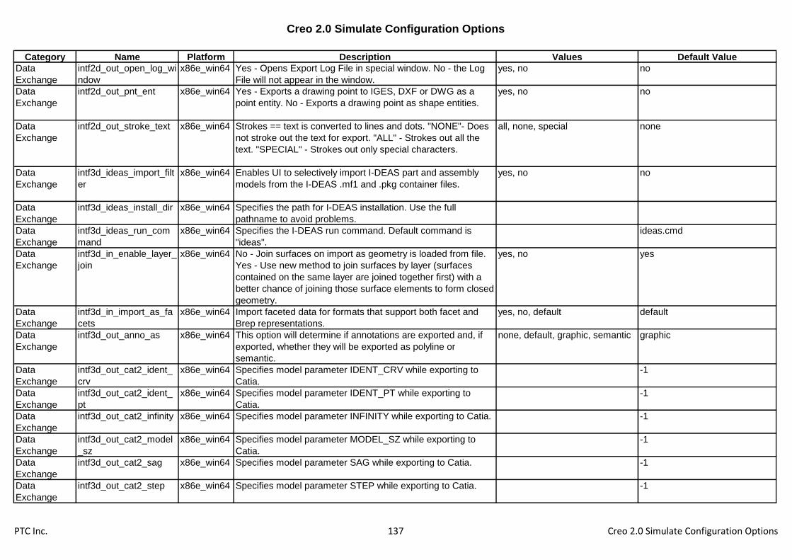
Creo 2.0 Simulate Configuration Options
Category Name Platform Description Values Default Value
Data
Exchange
intf2d_out_open_log_wi
ndow
x86e_win64 Yes - Opens Export Log File in special window. No - the Log
File will not appear in the window.
yes, no no
Data
Exchange
intf2d_out_pnt_ent x86e_win64 Yes - Exports a drawing point to IGES, DXF or DWG as a
point entity. No - Exports a drawing point as shape entities.
yes, no no
Data
Exchange
intf2d_out_stroke_text x86e_win64 Strokes == text is converted to lines and dots. "NONE"- Does
not stroke out the text for export. "ALL" - Strokes out all the
text. "SPECIAL" - Strokes out only special characters.
all, none, special none
Data
Exchange
intf3d_ideas_import_filt
er
x86e_win64 Enables UI to selectively import I-DEAS part and assembly
models from the I-DEAS .mf1 and .pkg container files.
yes, no no
Data
Exchange
intf3d_ideas_install_dir x86e_win64 Specifies the path for I-DEAS installation. Use the full
pathname to avoid problems.
Data
Exchange
intf3d_ideas_run_com
mand
x86e_win64 Specifies the I-DEAS run command. Default command is
"ideas".
ideas.cmd
Data
Exchange
intf3d_in_enable_layer_
join
x86e_win64 No - Join surfaces on import as geometry is loaded from file.
Yes - Use new method to join surfaces by layer (surfaces
contained on the same layer are joined together first) with a
better chance of joining those surface elements to form closed
geometry.
yes, no yes
Data
Exchange
intf3d_in_import_as_fa
cets
x86e_win64 Import faceted data for formats that support both facet and
Brep representations.
yes, no, default default
Data
Exchange
intf3d_out_anno_as x86e_win64 This option will determine if annotations are exported and, if
exported, whether they will be exported as polyline or
semantic.
none, default, graphic, semantic graphic
Data
Exchange
intf3d_out_cat2_ident_
crv
x86e_win64 Specifies model parameter IDENT_CRV while exporting to
Catia.
-1
Data
Exchange
intf3d_out_cat2_ident_
pt
x86e_win64 Specifies model parameter IDENT_PT while exporting to
Catia.
-1
Data
Exchange
intf3d_out_cat2_infinity x86e_win64 Specifies model parameter INFINITY while exporting to Catia. -1
Data
Exchange
intf3d_out_cat2_model
_sz
x86e_win64 Specifies model parameter MODEL_SZ while exporting to
Catia.
-1
Data
Exchange
intf3d_out_cat2_sag x86e_win64 Specifies model parameter SAG while exporting to Catia. -1
Data
Exchange
intf3d_out_cat2_step x86e_win64 Specifies model parameter STEP while exporting to Catia. -1
PTC Inc. 137 Creo 2.0 Simulate Configuration Options

Creo 2.0 Simulate Configuration Options
Category Name Platform Description Values Default Value
Data
Exchange
intf3d_out_datums_by_
default
x86e_win64 Determines whether datum curves are included when
exporting IGES files in Batch mode.
yes, no no
Data
Exchange
intf3d_out_default_opti
on
x86e_win64 Controls the type of 3-D data output through Pro/BATCH to an
IGES or STEP file.
none, wireframe, surfaces,
wireframe_surfaces, solid, shells
surfaces
Data
Exchange
intf3d_out_extend_surf
ace
x86e_win64 Specifies how surfaces are handled for exporting files to other
systems
yes, no yes
Data
Exchange
intf3d_out_force_surf_n
ormals
x86e_win64 IGES and PDGS export. Controls normals of non-analytic
surfaces. Yes - Forces the surface normals to point in a
consistent direction. No - Does not force the surface normals
to point in a consistent direction.
yes, no no
Data
Exchange
intf3d_out_jt_auto_lods x86e_win64 Generate three default Creo Parametric LODs. yes, no no
Data
Exchange
intf3d_out_jt_brep x86e_win64 No*: Export to JT as facet representation only, jt_brep: Export
to JT as facet and jt_brep representation, xt_brep: Export to
JT as facet and xt_brep representation
no, jt_brep, xt_brep no
Data
Exchange
intf3d_out_jt_structure x86e_win64 Specifies product structure to file structure mapping defined in
JT Open Toolkit.
per_part, fully_shattered,
monolithic
per_part
Data
Exchange
intf3d_out_parameters x86e_win64 Exports parameters with models. all, none, designated all
Data
Exchange
intf3d_out_prop_chord_
heights
x86e_win64 Use maximum chord heights proportional to component sizes. yes, no no
Data
Exchange
intf3d_out_prop_step_s
izes
x86e_win64 Use maximum step sizes proportional to component sizes. yes, no no
Data
Exchange
intf3d_out_surface_dev
iation
x86e_win64 Sets maximum allowable deviation between original and
resulting surfaces in the process of converting Creo
Parametric surfaces to spline surfaces. By setting this you
convert surfaces with a better approximation than by using the
current model accuracy.
-1
Data
Exchange
intf3d_out_unicode_to_
neutral
x86e_win64 YES - Unicode strings are exported to the Neutral file, NO -
Unicode strings are converted to ascii characters for Neutral
file export.
yes, no yes
Data
Exchange
intf3d_out_use_num_n
ames
x86e_win64 Use numeric layer names as layer export IDs. yes, no yes
Data
Exchange
intf3d_out_use_step_si
ze
x86e_win64 Use maximum step size(s). yes, no no
PTC Inc. 138 Creo 2.0 Simulate Configuration Options

Creo 2.0 Simulate Configuration Options
Category Name Platform Description Values Default Value
Data
Exchange
intf3d_parasolid_export
_schema
x86e_win64 Allows user to choose the schema to be used for parasolid
export. Default is SCH_10004. Consult online documentation
for other valid schema settings.
sch_10004
Data
Exchange
medusa_2d_config_file x86e_win64 Specifies the Medusa 2D Interface config. file. Absolute or
relative path to the file can be used.
Data
Exchange
mentor_ver_2_0 x86e_win64 Yes - Exports the file in IDF 2.0 format. No - Exports the file in
IDF 1.0 format unless IDF 2.0 is selected from the ECAD
FORMAT menu.
yes, no yes
Data
Exchange
pdf_linecap x86e_win64 0 - Butt cap: stroked lines are squared off at the endpoint of
the path. There is no projection beyond the end of the path.
butt, round, projecting square butt
Data
Exchange
pdf_linejoin x86e_win64 0 - Miter join: outer edges of the strokes for the two segments
are extended until they meet at an angle.
round, miter, bevel miter
Data
Exchange
pdf_use_pentable x86e_win64 No - PDF export does not use any defined pentable changes
as would be applied to plotting the drawing.
yes, no no
Data
Exchange
pro_gplug_dir x86e_win64 Specifies the directory in which Granite application plug-ins
are located. Use the full pathname to avoid problems.
<creo_loadpoint>\x86e_win64\g
plugs\
Data
Exchange
pro_stheno_command x86e_win64 Specifies the command for Stheno launch.
Data
Exchange
put_iges_drawing_entit
y
x86e_win64 Specifies whether or not to suppress the output of the IGES
drawing entity, #404, to the IGES file. No - The drawing entity
is not output.
yes, no yes
Data
Exchange
step_appearance_layer
s_groups
x86e_win64 No - Output of Appearances, Layers, and Groups is enabled
for STEP standard AP214. Yes - Output of Appearances,
Layers, and Groups is enabled for STEP standard AP203.
yes, no no
Data
Exchange
step_export_ap214_as
m_def_mode
x86e_win64 Toggles the default setting of the File Structure field in the
STEP Export dialog box for supported assembly STEP export
files.
single_file, separate_parts_only,
separate_all_objects
single_file
Data
Exchange
step_export_dwg_view
s
x86e_win64 AS_3D_VIEWS - Export 3-D model geometry with its
associative views. AS_3D_VIEWS_ASSOC_DRAFT - Export
3-D model geometry with its associative views and view
related annotations. NO - Export only 2-D representations of
the 3-D models. This is the default.
no, as_3d_views,
as_3d_views_assoc_draft
no
PTC Inc. 139 Creo 2.0 Simulate Configuration Options

Creo 2.0 Simulate Configuration Options
Category Name Platform Description Values Default Value
Data
Exchange
step_export_format x86e_win64 Specifies output format when exporting to STEP. AP203_IS -
Formats output to ISO 10303 AP203IS format. AP214_CD -
Formats output with geometry that meets the specification for
the long-term schema for AP214cc1.
ap203_is, ap202_is, ap209_dis,
ap214_is, ap203_e2,
ap203_is_ext
ap203_is
Data
Exchange
step_out_asm_val_pro
p
x86e_win64 Export validation information for assemblies to the STEP file
for formats ap203_e2, ap214_is
yes, no no
Data
Exchange
step_out_material x86e_win64 Exports the material definition (name and density) to the
STEP file for formats ap203_e2, ap214_is and 203_is_ext
yes, no no
Data
Exchange
step_out_material_as_
product
x86e_win64 Export the material definition (name and density) to the STEP
file as a separate STEP PRODUCT entity
yes, no no
Data
Exchange
step_out_suppl_geom x86e_win64 Export datum csys, planes, axes, points to the STEP file for
formats ap203_e2, ap214_is
yes, no no
Data
Exchange
system_iges_header_fil
e
x86e_win64 Inserts specified text file into the Start section of IGES files
(refer to user_iges_header_file). When used with
user_iges_header_file, the system text appears first.
Data
Exchange
template_boardpart x86e_win64 Specify the model to use as the default new ECAD board
template.
Data
Exchange
template_new_ecadas
m
x86e_win64 Specify the model to use as the default new ECAD assembly
template.
Data
Exchange
tiff_compression x86e_win64 TIFF exports are done without compression. none, g4, packbits, deflate none
Data
Exchange
tiff_type x86e_win64 Determines the type of tiff items are exported to variables
refer to color sets
rgb, palette, grayscale, mono rgb
Data
Exchange
use_export_2d_dialog x86e_win64 Yes - Opens export options dialog when exporting Creo
Parametric drawing. No - exports file without the options
dialog.
yes, no yes
Data
Exchange
use_iges_font_1003 x86e_win64 Used to disable the use of IGES font 1003. yes, no yes
Data
Exchange
use_iges_kanji_font_20
01
x86e_win64 Specifies whether to convert Kanji notes in Creo Parametric to
IGES Kanji notes (font code) when exporting. Yes - Converts
Kanji notes to IGES Kanji notes. No - Converts using Font 1.
yes, no no
PTC Inc. 140 Creo 2.0 Simulate Configuration Options

Creo 2.0 Simulate Configuration Options
Category Name Platform Description Values Default Value
Data
Exchange
user_iges_header_file x86e_win64 Filename - Insert specified text file into the Start section of
IGES file. Valid parametric note symbols will be replaced
during export. For example, &dwg_name in the text file is
replaced by the drawing name when a drawing is exported.
Data
Exchange
vda_header x86e_win64 The complete filename of the text file containing VDA header
information. If you intend to use the same header for all VDA
files, specify the full pathname.
Data
Exchange
vrml_anchor_url x86e_win64 Enables you to place an anchor on a specified VRML
component during the export to VRML. The keywords are
optional.
Data
Exchange
vrml_background_color x86e_win64 Yes - Exports a model to VRML with the Creo Parametric
background color.
yes, no no
Data
Exchange
vrml_explode_lines x86e_win64 Yes - Exports a model to VRML with explode lines for
assembly or assembly process data.
yes, no yes
Data
Exchange
vrml_export_resolution x86e_win64 Specifies the number of levels of detail (LODs) in models
exported in VRML format.
high, medium, low medium
Data
Exchange
vrml_export_version x86e_win64 Allows the user to choose between exporting to the VRML 2.0
or 1.0 format.
2.0, 1.0 2
Data
Exchange
vrml_file_duplicate_mat
erial
x86e_win64 Yes - Ensures that the model components retain their true
color. No - In some viewers, component colors might not be
consistent.
yes, no no
Data
Exchange
vrml_multiple_views x86e_win64 All - Exports top-level and lower-level assembly component
views into VRML format. None - Does not export component
views into VRML format. Top - Exports top-level object view
only into VRML format.
all, none, top all
Data
Exchange
vrml_parameters x86e_win64 Controls the export of user parameters. Designated - Export
only designated parameters. All - Export all parameters. None -
Do not export parameters.
all, none, designated designated
Data
Exchange
vrml_simprep_export x86e_win64 Yes - Specifies direct and in memory export of top-level
assembly simplified representation to Pro/FLY-THROUGH
package files.
yes, no no
Data
Exchange
www_add_aux_frame x86e_win64 Creates additional frame for each process step or for
assembly publication. Yes - Auxiliary files aux.html are created
for each step in assembly process (in each step00 directory)
to be replaced by your .html file. No - Auxiliary files are not
created.
yes, no no
PTC Inc. 141 Creo 2.0 Simulate Configuration Options
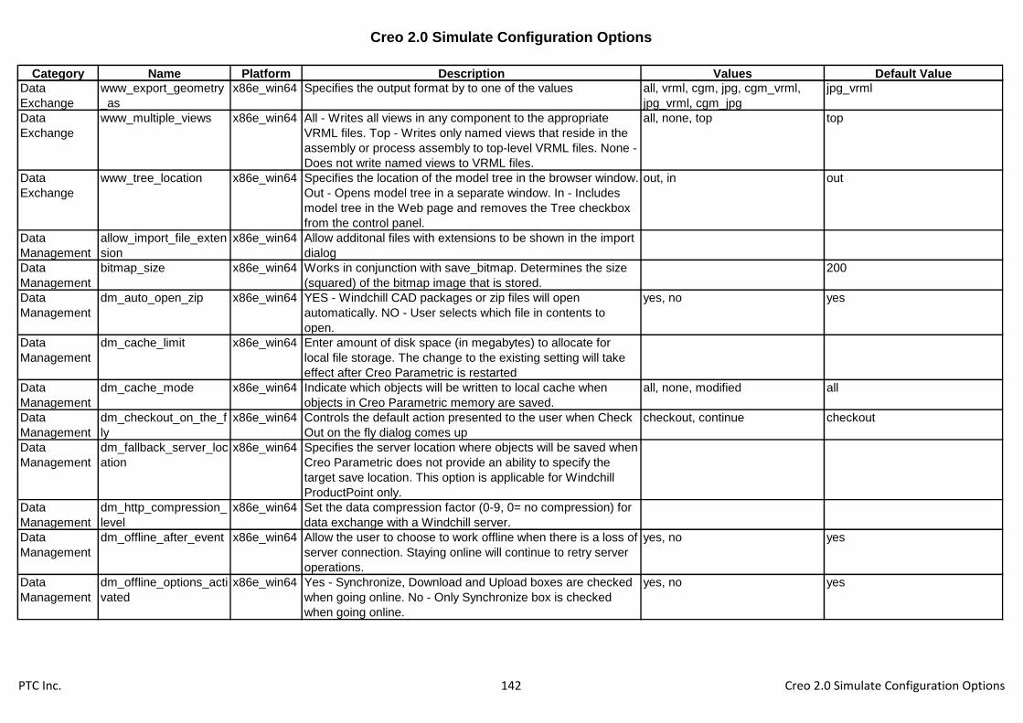
Creo 2.0 Simulate Configuration Options
Category Name Platform Description Values Default Value
Data
Exchange
www_export_geometry
_as
x86e_win64 Specifies the output format by to one of the values all, vrml, cgm, jpg, cgm_vrml,
jpg_vrml, cgm_jpg
jpg_vrml
Data
Exchange
www_multiple_views x86e_win64 All - Writes all views in any component to the appropriate
VRML files. Top - Writes only named views that reside in the
assembly or process assembly to top-level VRML files. None -
Does not write named views to VRML files.
all, none, top top
Data
Exchange
www_tree_location x86e_win64 Specifies the location of the model tree in the browser window.
Out - Opens model tree in a separate window. In - Includes
model tree in the Web page and removes the Tree checkbox
from the control panel.
out, in out
Data
Management
allow_import_file_exten
sion
x86e_win64 Allow additonal files with extensions to be shown in the import
dialog
Data
Management
bitmap_size x86e_win64 Works in conjunction with save_bitmap. Determines the size
(squared) of the bitmap image that is stored.
200
Data
Management
dm_auto_open_zip x86e_win64 YES - Windchill CAD packages or zip files will open
automatically. NO - User selects which file in contents to
open.
yes, no yes
Data
Management
dm_cache_limit x86e_win64 Enter amount of disk space (in megabytes) to allocate for
local file storage. The change to the existing setting will take
effect after Creo Parametric is restarted
Data
Management
dm_cache_mode x86e_win64 Indicate which objects will be written to local cache when
objects in Creo Parametric memory are saved.
all, none, modified all
Data
Management
dm_checkout_on_the_f
ly
x86e_win64 Controls the default action presented to the user when Check
Out on the fly dialog comes up
checkout, continue checkout
Data
Management
dm_fallback_server_loc
ation
x86e_win64 Specifies the server location where objects will be saved when
Creo Parametric does not provide an ability to specify the
target save location. This option is applicable for Windchill
ProductPoint only.
Data
Management
dm_http_compression_
level
x86e_win64 Set the data compression factor (0-9, 0= no compression) for
data exchange with a Windchill server.
Data
Management
dm_offline_after_event x86e_win64 Allow the user to choose to work offline when there is a loss of
server connection. Staying online will continue to retry server
operations.
yes, no yes
Data
Management
dm_offline_options_acti
vated
x86e_win64 Yes - Synchronize, Download and Upload boxes are checked
when going online. No - Only Synchronize box is checked
when going online.
yes, no yes
PTC Inc. 142 Creo 2.0 Simulate Configuration Options
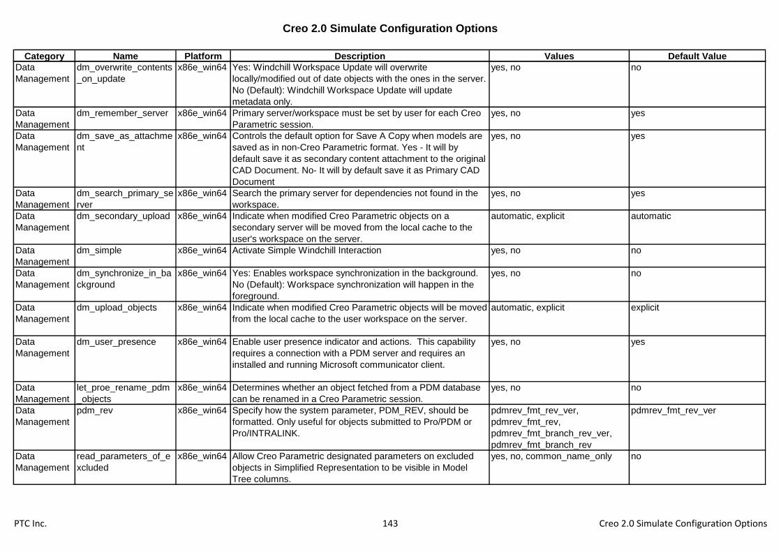
Creo 2.0 Simulate Configuration Options
Category Name Platform Description Values Default Value
Data
Management
dm_overwrite_contents
_on_update
x86e_win64 Yes: Windchill Workspace Update will overwrite
locally/modified out of date objects with the ones in the server.
No (Default): Windchill Workspace Update will update
metadata only.
yes, no no
Data
Management
dm_remember_server x86e_win64 Primary server/workspace must be set by user for each Creo
Parametric session.
yes, no yes
Data
Management
dm_save_as_attachme
nt
x86e_win64 Controls the default option for Save A Copy when models are
saved as in non-Creo Parametric format. Yes - It will by
default save it as secondary content attachment to the original
CAD Document. No- It will by default save it as Primary CAD
Document
yes, no yes
Data
Management
dm_search_primary_se
rver
x86e_win64 Search the primary server for dependencies not found in the
workspace.
yes, no yes
Data
Management
dm_secondary_upload x86e_win64 Indicate when modified Creo Parametric objects on a
secondary server will be moved from the local cache to the
user's workspace on the server.
automatic, explicit automatic
Data
Management
dm_simple x86e_win64 Activate Simple Windchill Interaction yes, no no
Data
Management
dm_synchronize_in_ba
ckground
x86e_win64 Yes: Enables workspace synchronization in the background.
No (Default): Workspace synchronization will happen in the
foreground.
yes, no no
Data
Management
dm_upload_objects x86e_win64 Indicate when modified Creo Parametric objects will be moved
from the local cache to the user workspace on the server.
automatic, explicit explicit
Data
Management
dm_user_presence x86e_win64 Enable user presence indicator and actions. This capability
requires a connection with a PDM server and requires an
installed and running Microsoft communicator client.
yes, no yes
Data
Management
let_proe_rename_pdm
_objects
x86e_win64 Determines whether an object fetched from a PDM database
can be renamed in a Creo Parametric session.
yes, no no
Data
Management
pdm_rev x86e_win64 Specify how the system parameter, PDM_REV, should be
formatted. Only useful for objects submitted to Pro/PDM or
Pro/INTRALINK.
pdmrev_fmt_rev_ver,
pdmrev_fmt_rev,
pdmrev_fmt_branch_rev_ver,
pdmrev_fmt_branch_rev
pdmrev_fmt_rev_ver
Data
Management
read_parameters_of_e
xcluded
x86e_win64 Allow Creo Parametric designated parameters on excluded
objects in Simplified Representation to be visible in Model
Tree columns.
yes, no, common_name_only no
PTC Inc. 143 Creo 2.0 Simulate Configuration Options

Creo 2.0 Simulate Configuration Options
Category Name Platform Description Values Default Value
Data
Management
regenerate_read_only_
objects
x86e_win64 Determines whether an object retrieved from PDM database
with read only status can be regenerated in a Creo Parametric
session.
yes, no yes
Data
Management
save_bitmap x86e_win64 When performing a save on a model, determines what level of
the assembly will have bitmap images created of modified
components.
none, toplevelonly, alllevels none
Data
Management
save_bitmap_type x86e_win64 When performing a save on a model, determines the type of
image file that is created for that model. Used with
"save_bitmap" option.
cgm, bmp, tiff, gif, jpeg bmp
Data
Management
save_unchanged_pdm
_object
x86e_win64 Determines how to save in the current working directory an
object fetched from a Pro/PDM database into a Creo
Parametric session.
as_ref, as_copy as_ref
Design
Manager
dont_show_symbol_no
des
x86e_win64 Do not show references derived from relations in Parent/Child
viewer.
yes, no no
Dimensions &
Tolerances
allow_rfs_default_gtols
_always
x86e_win64 Yes - Enables RFS/Default gtols to be created even when not
permitted by ANSI standard.
yes, no no
Dimensions &
Tolerances
ang_dim_in_screen x86e_win64 Yes - If the display is in the default pan/zoom setting
(View>Pan/Zoom>Reset), the system checks whether an
angular dimension is visible on the screen. If it is not visible,
then the system moves the dimension to a visible location.
yes, no no
Dimensions &
Tolerances
angular_tol x86e_win64 An alternative format for setting default angular tolerance
dimensions. The value sets the number of decimal places,
and the tolerance is the actual tolerance value. For integer
dimensions, the value is zero, and the tolerance is an integer.
0
Dimensions &
Tolerances
angular_tol_0.0 x86e_win64 Sets the default tolerance for angular dimensions. Each option
sets a tolerance for a specific decimal place. The value is the
place of the last decimal.
5
Dimensions &
Tolerances
angular_tol_0.00 x86e_win64 Sets the default tolerance for angular dimensions. Each option
sets a tolerance for a specific decimal place. The value is the
place of the last decimal.
50
Dimensions &
Tolerances
angular_tol_0.000 x86e_win64 Sets the default tolerance for angular dimensions. Each option
sets a tolerance for a specific decimal place. The value is the
place of the last decimal.
500
PTC Inc. 144 Creo 2.0 Simulate Configuration Options
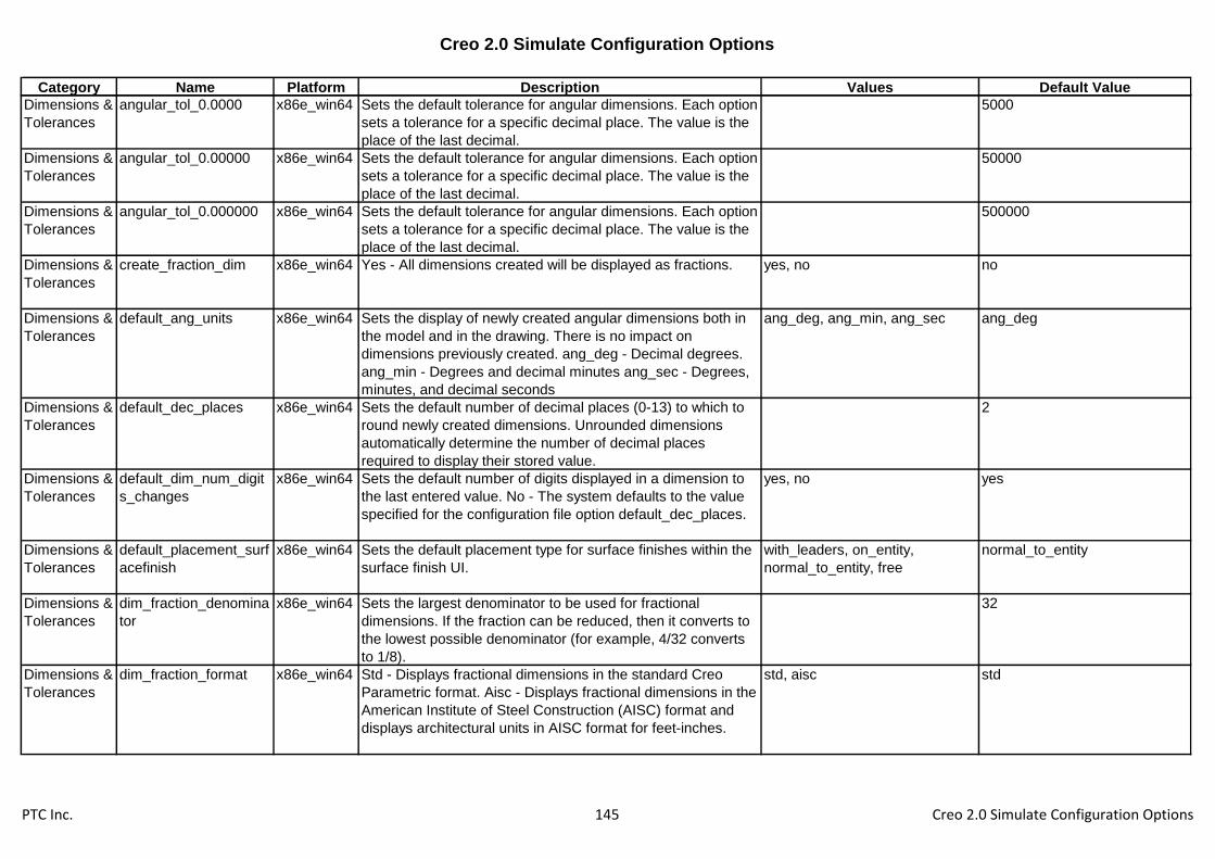
Creo 2.0 Simulate Configuration Options
Category Name Platform Description Values Default Value
Dimensions &
Tolerances
angular_tol_0.0000 x86e_win64 Sets the default tolerance for angular dimensions. Each option
sets a tolerance for a specific decimal place. The value is the
place of the last decimal.
5000
Dimensions &
Tolerances
angular_tol_0.00000 x86e_win64 Sets the default tolerance for angular dimensions. Each option
sets a tolerance for a specific decimal place. The value is the
place of the last decimal.
50000
Dimensions &
Tolerances
angular_tol_0.000000 x86e_win64 Sets the default tolerance for angular dimensions. Each option
sets a tolerance for a specific decimal place. The value is the
place of the last decimal.
500000
Dimensions &
Tolerances
create_fraction_dim x86e_win64 Yes - All dimensions created will be displayed as fractions. yes, no no
Dimensions &
Tolerances
default_ang_units x86e_win64 Sets the display of newly created angular dimensions both in
the model and in the drawing. There is no impact on
dimensions previously created. ang_deg - Decimal degrees.
ang_min - Degrees and decimal minutes ang_sec - Degrees,
minutes, and decimal seconds
ang_deg, ang_min, ang_sec ang_deg
Dimensions &
Tolerances
default_dec_places x86e_win64 Sets the default number of decimal places (0-13) to which to
round newly created dimensions. Unrounded dimensions
automatically determine the number of decimal places
required to display their stored value.
2
Dimensions &
Tolerances
default_dim_num_digit
s_changes
x86e_win64 Sets the default number of digits displayed in a dimension to
the last entered value. No - The system defaults to the value
specified for the configuration file option default_dec_places.
yes, no yes
Dimensions &
Tolerances
default_placement_surf
acefinish
x86e_win64 Sets the default placement type for surface finishes within the
surface finish UI.
with_leaders, on_entity,
normal_to_entity, free
normal_to_entity
Dimensions &
Tolerances
dim_fraction_denomina
tor
x86e_win64 Sets the largest denominator to be used for fractional
dimensions. If the fraction can be reduced, then it converts to
the lowest possible denominator (for example, 4/32 converts
to 1/8).
32
Dimensions &
Tolerances
dim_fraction_format x86e_win64 Std - Displays fractional dimensions in the standard Creo
Parametric format. Aisc - Displays fractional dimensions in the
American Institute of Steel Construction (AISC) format and
displays architectural units in AISC format for feet-inches.
std, aisc std
PTC Inc. 145 Creo 2.0 Simulate Configuration Options

Creo 2.0 Simulate Configuration Options
Category Name Platform Description Values Default Value
Dimensions &
Tolerances
dim_offscreen_limit x86e_win64 If more than zero, sets the margin beyond which dimensions
are automatically snapped back onto the screen. For
example, a value of .2 lets a dimension be 20% of the window
size outside the window. If set to zero, disables snapping of
offscreen dimensions.
0.2
Dimensions &
Tolerances
display_tol_by_1000 x86e_win64 If set to Yes, tolerances for non-angular dimensions will be
displayed multiplied by 1000.
yes, no no
Dimensions &
Tolerances
gtol_dim_placement x86e_win64 Controls display of geometric tolerances in Part. Use like
drawing set-up option of the same name. On_bottom - Gtols
display at bottom (below additional lines of text). Under_value -
Gtols display under dimension value (above additional lines of
text).
on_bottom, under_value on_bottom
Dimensions &
Tolerances
linear_tol x86e_win64 An alternate format for setting default linear tolerance
dimensions. First value sets the number of decimal places.
Second value is the actual tolerance. For example, 6
0.000025 sets tolerance to six decimal places. The default
tolerance is 0.000025.
0.000000 -1
Dimensions &
Tolerances
linear_tol_0.0 x86e_win64 Specify a range for default tolerances of linear and angular
dimensions. These values affect only models created after the
tolerance options are specified in the configuration file.
1
Dimensions &
Tolerances
linear_tol_0.00 x86e_win64 Specify a range for default tolerances of linear and angular
dimensions. These values affect only models created after the
tolerance options are specified in the configuration file.
1
Dimensions &
Tolerances
linear_tol_0.000 x86e_win64 Specify a range for default tolerances of linear and angular
dimensions. These values affect only models created after the
tolerance options are specified in the configuration file.
1
Dimensions &
Tolerances
linear_tol_0.0000 x86e_win64 Specify a range for default tolerances of linear and angular
dimensions. These values affect only models created after the
tolerance options are specified in the configuration file.
1
Dimensions &
Tolerances
linear_tol_0.00000 x86e_win64 Specify a range for default tolerances of linear and angular
dimensions. These values affect only models created after the
tolerance options are specified in the configuration file.
1
PTC Inc. 146 Creo 2.0 Simulate Configuration Options

Creo 2.0 Simulate Configuration Options
Category Name Platform Description Values Default Value
Dimensions &
Tolerances
linear_tol_0.000000 x86e_win64 Specify a range for default tolerances of linear and angular
dimensions. These values affect only models created after the
tolerance options are specified in the configuration file.
1
Dimensions &
Tolerances
maintain_limit_tol_nomi
nal
x86e_win64 Maintains the nominal value of a dimension regardless of the
changes that you make to the tolerance values.
yes, no no
Dimensions &
Tolerances
mark_approximate_dim
s
x86e_win64 Yes - Displays a tilde (~) in front of a dimension that is set to
display as a fraction and has an actual value that is not
rounded to equate exactly to the displayed fractional value
(the fraction shows 7/32 but the actual value is .22, not
0.21875).
yes, no no
Dimensions &
Tolerances
minimum_angle_dimen
sion
x86e_win64 Controls the minimum angle value under which Creo
Parametric assumes colinearity of the selected items when
creating a driven dimension.
1
Dimensions &
Tolerances
parenthesize_ref_dim x86e_win64 Encloses reference dimensions in parentheses. No - Follows
reference dimensions with the text "REF".
yes, no no
Dimensions &
Tolerances
restricted_gtol_dialog x86e_win64 Determines whether the Geometric Tolerance dialog restricts
the user by graying out elements that are considered "illegal".
yes, no yes
Dimensions &
Tolerances
round_displayed_dim_v
alues
x86e_win64 Sets the default status of the Round Displayed Value
checkbox for new and newly shown dimensions.
yes, no yes
Dimensions &
Tolerances
tbl_driven_tol_val_edit x86e_win64 Tbl_driven_tol_val_edit Y/N* - "Yes" allows users to directly
edit the tolerance value of dimensions whose tolerance values
are driven by tolerance tables. Editing the tolerance value of a
dimension will make the dimension non-table-driven. "No"
disallows direct editing of the tolerance values of table driven
tolerances.
yes, no no
Dimensions &
Tolerances
tol_display x86e_win64 Displays dimensions with or without tolerances. yes, no no
Dimensions &
Tolerances
tolerance_class x86e_win64 Sets the default tolerance class for ISO-standard models. The
system uses the tolerance class in conjunction with the
dimension value when retrieving tolerances for General or
Broken Edge dimensions.
medium, fine, coarse,
very_coarse
PTC Inc. 147 Creo 2.0 Simulate Configuration Options

Creo 2.0 Simulate Configuration Options
Category Name Platform Description Values Default Value
Dimensions &
Tolerances
tolerance_standard x86e_win64 Sets the tolerance standard used when creating the model. ansi, iso ansi
Dimensions &
Tolerances
tolerance_table_dir x86e_win64 Sets the default directory for user-defined tolerance tables for
ISO-standard models. All Holes and Shafts tables overwrite
existing tables when loaded.
Dimensions &
Tolerances
use_major_units x86e_win64 Determines if fractional dimensions are displayed in terms of
feet-inches or meter-mm. Yes - The major units are used. For
example, when the units are inches and 25.125 is converted
to a fraction, the dimension becomes 2' 1-1/8".
yes, no no
Dimensions &
Tolerances
use_nom_dim_val_in_
expr
x86e_win64 Yes - use dimensions' nominal values in expressions. No -
use current values.
yes, no no
Drawing allow_move_attach_in_
dtl_move
x86e_win64 Yes - Move and Move Attach commands in drawing mode act
together. No - Move and Move Attach commands in drawing
mode do not act together.
yes, no yes
Drawing allow_move_view_with
_move
x86e_win64 Disallow the movement of drawing views with the mouse. yes, no no
Drawing allow_refs_to_geom_re
ps_in_drws
x86e_win64 Yes - Allows you to create drawing references to geometry
representations (includes dimensions, notes, and leaders).
These references may become invalid if the referenced
geometry changes resulting in geometry representations not
updating in drawings.
yes, no no
Drawing auto_constr_offset_tole
rance
x86e_win64 Sets the auto constraint tolerance for creating offset
dimensions. If distance is less than this tolerance multiplied by
component size, offset is set as coincident. Default value is
0.5 .
0.5
Drawing auto_regen_views x86e_win64 Yes - Automatically repaints the drawing display when
changing from one window to another. No - Update to drawing
views will only occur when manual updates are made via
Repaint or View> Update.
yes, no yes
Drawing autobuildz_enabled x86e_win64 Loads AutobuildZ application. yes, no no
Drawing bom_format x86e_win64 Sets the BOM format file to be used for a customized BOM.
Specify name and path.
<creo_loadpoint>\text\format.bft
PTC Inc. 148 Creo 2.0 Simulate Configuration Options
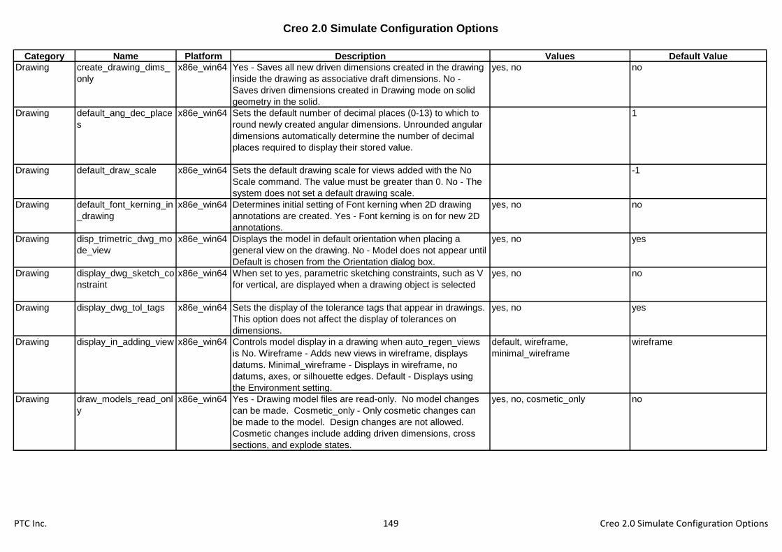
Creo 2.0 Simulate Configuration Options
Category Name Platform Description Values Default Value
Drawing create_drawing_dims_
only
x86e_win64 Yes - Saves all new driven dimensions created in the drawing
inside the drawing as associative draft dimensions. No -
Saves driven dimensions created in Drawing mode on solid
geometry in the solid.
yes, no no
Drawing default_ang_dec_place
s
x86e_win64 Sets the default number of decimal places (0-13) to which to
round newly created angular dimensions. Unrounded angular
dimensions automatically determine the number of decimal
places required to display their stored value.
1
Drawing default_draw_scale x86e_win64 Sets the default drawing scale for views added with the No
Scale command. The value must be greater than 0. No - The
system does not set a default drawing scale.
-1
Drawing default_font_kerning_in
_drawing
x86e_win64 Determines initial setting of Font kerning when 2D drawing
annotations are created. Yes - Font kerning is on for new 2D
annotations.
yes, no no
Drawing disp_trimetric_dwg_mo
de_view
x86e_win64 Displays the model in default orientation when placing a
general view on the drawing. No - Model does not appear until
Default is chosen from the Orientation dialog box.
yes, no yes
Drawing display_dwg_sketch_co
nstraint
x86e_win64 When set to yes, parametric sketching constraints, such as V
for vertical, are displayed when a drawing object is selected
yes, no no
Drawing display_dwg_tol_tags x86e_win64 Sets the display of the tolerance tags that appear in drawings.
This option does not affect the display of tolerances on
dimensions.
yes, no yes
Drawing display_in_adding_view x86e_win64 Controls model display in a drawing when auto_regen_views
is No. Wireframe - Adds new views in wireframe, displays
datums. Minimal_wireframe - Displays in wireframe, no
datums, axes, or silhouette edges. Default - Displays using
the Environment setting.
default, wireframe,
minimal_wireframe
wireframe
Drawing draw_models_read_onl
y
x86e_win64 Yes - Drawing model files are read-only. No model changes
can be made. Cosmetic_only - Only cosmetic changes can
be made to the model. Design changes are not allowed.
Cosmetic changes include adding driven dimensions, cross
sections, and explode states.
yes, no, cosmetic_only no
PTC Inc. 149 Creo 2.0 Simulate Configuration Options
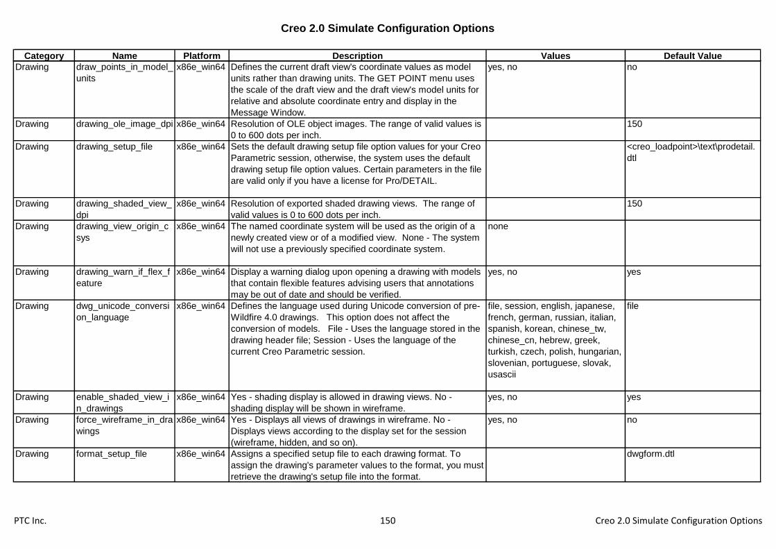
Creo 2.0 Simulate Configuration Options
Category Name Platform Description Values Default Value
Drawing draw_points_in_model_
units
x86e_win64 Defines the current draft view's coordinate values as model
units rather than drawing units. The GET POINT menu uses
the scale of the draft view and the draft view's model units for
relative and absolute coordinate entry and display in the
Message Window.
yes, no no
Drawing drawing_ole_image_dpi x86e_win64 Resolution of OLE object images. The range of valid values is
0 to 600 dots per inch.
150
Drawing drawing_setup_file x86e_win64 Sets the default drawing setup file option values for your Creo
Parametric session, otherwise, the system uses the default
drawing setup file option values. Certain parameters in the file
are valid only if you have a license for Pro/DETAIL.
<creo_loadpoint>\text\prodetail.
dtl
Drawing drawing_shaded_view_
dpi
x86e_win64 Resolution of exported shaded drawing views. The range of
valid values is 0 to 600 dots per inch.
150
Drawing drawing_view_origin_c
sys
x86e_win64 The named coordinate system will be used as the origin of a
newly created view or of a modified view. None - The system
will not use a previously specified coordinate system.
none
Drawing drawing_warn_if_flex_f
eature
x86e_win64 Display a warning dialog upon opening a drawing with models
that contain flexible features advising users that annotations
may be out of date and should be verified.
yes, no yes
Drawing dwg_unicode_conversi
on_language
x86e_win64 Defines the language used during Unicode conversion of pre-
Wildfire 4.0 drawings. This option does not affect the
conversion of models. File - Uses the language stored in the
drawing header file; Session - Uses the language of the
current Creo Parametric session.
file, session, english, japanese,
french, german, russian, italian,
spanish, korean, chinese_tw,
chinese_cn, hebrew, greek,
turkish, czech, polish, hungarian,
slovenian, portuguese, slovak,
usascii
file
Drawing enable_shaded_view_i
n_drawings
x86e_win64 Yes - shading display is allowed in drawing views. No -
shading display will be shown in wireframe.
yes, no yes
Drawing force_wireframe_in_dra
wings
x86e_win64 Yes - Displays all views of drawings in wireframe. No -
Displays views according to the display set for the session
(wireframe, hidden, and so on).
yes, no no
Drawing format_setup_file x86e_win64 Assigns a specified setup file to each drawing format. To
assign the drawing's parameter values to the format, you must
retrieve the drawing's setup file into the format.
dwgform.dtl
PTC Inc. 150 Creo 2.0 Simulate Configuration Options

Creo 2.0 Simulate Configuration Options
Category Name Platform Description Values Default Value
Drawing highlight_erased_dwg_
views
x86e_win64 Controls the display of erased view outlines (environment
option Highlight Erased Views). Yes - Highlights erased views.
No - Turns off highlighting for erased views.
yes, no yes
Drawing highlight_new_dims x86e_win64 In drawing mode, highlights new dimensions in red until you
repaint the screen.
yes, no no
Drawing hlr_for_quilts x86e_win64 In Drawing, controls quilt display in hidden line removal. Yes -
Includes quilts in the hidden line removal process (preselects
Qlt HLR in the VIEW DISP menu). Default in the VIEW DISP
menu, uses the value you have set.
yes, no no
Drawing make_aux_view_notes x86e_win64 Automatically adds view names to auxiliary views using AUX
VIEW* viewname-viewname. You can modify the view name
after adding the view to the drawing.
yes, no no
Drawing make_parameters_fro
m_fmt_tables
x86e_win64 Determines the handling of values entered in a format table
when you replace one drawing format with another. Yes -
Stores entered values for format table and copies them with
the table. No - Prompts you to re-enter all the values for the
format table.
yes, no no
Drawing make_proj_view_notes x86e_win64 Automatically adds view names to projection views in the
format "VIEW viewname-viewname." You can modify the view
name after adding the view to the drawing.
yes, no no
Drawing pick_chain_tangent_onl
y
x86e_win64 Specifies the extent of draft entity chains selected. Yes - Only
entities in the chain that are tangent will be selected. No - All
entities connected end to end will be selected.
yes, no no
Drawing preferred_export_forma
t
x86e_win64 Set the default preferred export file type for export from
drawings.
cgm, tiff, iges, dxf, step, pdf,
dwg, medusa, stheno
Drawing pro_dtl_setup_dir x86e_win64 Sets the directory for the drawing setup files. If this option is
not set, the system uses the default setup directory.
Drawing pro_format_dir x86e_win64 Sets the default directory for the drawing format library. Use
the full pathname to avoid problems.
Drawing pro_note_dir x86e_win64 Specifies the directory from which to retrieve notes entered
from a file. Use the full path name to avoid problems.
<dir_name>\dump_x86e_win64\
Drawing pro_palette_dir x86e_win64 Sets the default directory for drawing symbol palette files. <creo_loadpoint>\symbols\palett
e\
PTC Inc. 151 Creo 2.0 Simulate Configuration Options

Creo 2.0 Simulate Configuration Options
Category Name Platform Description Values Default Value
Drawing pro_symbol_dir x86e_win64 Set and automatically create the default directory for saving
and retrieving user-defined symbols. If you do not specify a
directory, the system uses the current working directory. Use
full path name to avoid problems.
<dir_name>\dump_x86e_win64\
Drawing pro_table_dir x86e_win64 Specifies the directory to be used when tables are retrieved or
saved. Use the full path name to avoid problems.
Drawing remember_last_get_poi
nt_option
x86e_win64 Yes - Sets the default of the GET POINT menu as the last
option picked among Pick Pnt, Vertex and On Entity.
yes, no no
Drawing save_display x86e_win64 Yes - Stores view geometry and detail items such as solid
dimensions. These items are displayed when retrieving the
drawing in View-Only mode.
yes, no no
Drawing save_drawing_picture_f
ile
x86e_win64 Embed - Embeds a picture file inside a drawing for preview
purposes. Export - Saves a drawing file as a picture file in the
working directory when saving a drawing. Both - Does both
embed and export.
no, export, embed, both embed
Drawing save_modified_draw_
models_only
x86e_win64 Determines whether the system saves the model after you
have changed it. No - Saves the model every time that you
store the drawing.
yes, no yes
Drawing select_hidden_edges_i
n_dwg
x86e_win64 Controls selectability of hidden edges in no-hidden drawing
views.
yes, no yes
Drawing selection_of_removed_
entities
x86e_win64 Yes - Entities in front of cross-section (planar or offset) can be
selected, clipped (using Z-clipping), or erased with EDGE
DISP menu. No - Geometry, datum points or curves, cosmetic
features, threads, grooves, or coordinate systems cannot be
erased.
yes, no no
Drawing show_annotations_dial
og_limit
x86e_win64 Default value for Annotations dialog box.
Drawing show_preview_default x86e_win64 This option determines the default behavior for preview in
Show/Erase.
remove, keep remove
Drawing switch_dims_for_notes x86e_win64 Yes - Dimensions will be displayed in their symbolic format
during drawing note creation. No - Dimensions will be
displayed in drawing notes as numerical values.
yes, no yes
Drawing sym_leader_orient_mo
ve_text
x86e_win64 With Pro/DETAIL, automatically regroups weld symbol
instances after you move the text.
yes, no no
Drawing symbol_instance_palett
e_file
x86e_win64 Specifies the location of the symbol instance palette.
PTC Inc. 152 Creo 2.0 Simulate Configuration Options

Creo 2.0 Simulate Configuration Options
Category Name Platform Description Values Default Value
Drawing symbol_palette_input x86e_win64 Controls the display of the special symbol palette during note
creation.
yes, no yes
Drawing todays_date_note_form
at
x86e_win64 Controls the initial format of the date displayed in a drawing.
The format for the setting is a string consisting of three
portions: the year, the month, and the date. You can enter the
portions in any order.
%dd-%mmm-%yy
Drawing tol_num_digits_default_
driven
x86e_win64 Yes - The Default check boxes in the number of digits area of
the Dimension Properties dialog will be checked when a
dimension is created or first shown. No - The check boxes will
be unchecked when a dimension is created or first shown.
yes, no yes
Drawing triangulate_filled_areas x86e_win64 Subdivide filled areas into triangles (may affect memory usage
and plot files).
yes, no no
Drawing variant_drawing_item_s
izes
x86e_win64 No - Drawing items moved/copied to a different sheet or
located on a changed sheet keep same size and relative
orientation on paper. Yes - Some items scale/reposition to be
the same on paper, and others scale and/or reposition to be
the same on screen.
yes, no no
Electromecha
nical
align_cable_bundles x86e_win64 Align NEWLY CREATED bundles where they meet or branch
out
yes, no yes
Electromecha
nical
allow_harn_mfg_assy_r
etrieval
x86e_win64 Allow to retrieve a harness mfg assembly directly. yes, no no
Electromecha
nical
assemble_parent_conn
ector
x86e_win64 Assemble parent connectors on locations referencing a
subconnector.
yes, no yes
Electromecha
nical
auto_convert_cables x86e_win64 Yes - When regenerating a pre-Release 11.0 cabling
assembly, the system automatically creates a separate spool
feature for every individual wire or cable in the assembly. No -
An interface for the cable conversion appears.
yes, no yes
Electromecha
nical
auto_xml_on_retrieve x86e_win64 Automatically load Cabling Logical Reference from an XML
file when retrieving the cabling assembly
yes, no no
Electromecha
nical
auto_xml_on_save x86e_win64 Automatically create an XML Logical Reference when saving
a cabling assembly
yes, no no
Electromecha
nical
autoroute_path_param
_name
x86e_win64 Set the wire parameter to use to select a path during
autorouting.
use_path
Electromecha
nical
cable_int_portions_for_
clr
x86e_win64 No - Global clearance checking for internal cable portions is
excluded. Yes - Global clearance checking for internal cable
portions is included.
yes, no no
PTC Inc. 153 Creo 2.0 Simulate Configuration Options

Creo 2.0 Simulate Configuration Options
Category Name Platform Description Values Default Value
Electromecha
nical
cable_location_override
_color
x86e_win64 Override the system color of cable locations. Enter RGB
values between 0 and 255 separated by space.
Electromecha
nical
cable_segment_overrid
e_color
x86e_win64 Override the system color of cable segments that do not have
a color map. Enter RGB values between 0 and 255 separated
by space.
Electromecha
nical
cables_with_hlr x86e_win64 Cables are not hidden behind objects. yes, no yes
Electromecha
nical
cabling_split_multi_pnt
_locs
x86e_win64 Setup whether to convert multiple-location features into single
location features.
yes, no yes
Electromecha
nical
compact_cables_packi
ng
x86e_win64 Setup whether the new packing of cables should be applied. yes, no no
Electromecha
nical
cti_class_color_file x86e_win64 Sets the CTI class color file for CTI class color display during
electrical clearance and creepage analysis. Use the full
pathname to avoid problems.
Electromecha
nical
diagram_export_allow x86e_win64 YES: Allow user to save a copy of loaded diagrams as DGE
file for loading into Routed Systems Designer, NO: Do not
provide option to save a diagram as DGE.
yes, no no
Electromecha
nical
diagram_pin_edit_multi
_line
x86e_win64 (Diagram) Determines the Pro/TABLE format used when you
are modifying pin parameters. "yes" - You can add user-
defined pin parameters by including them between the
DEFINE and ENDDEF statements for each pin. "no" - The
system uses columnar format and
yes, no no
Electromecha
nical
display_duplicate_harn
ess_msg
x86e_win64 Display warning message when duplicate harness are
identified in the same assembly.
yes, no yes
Electromecha
nical
display_internal_cable_
portion
x86e_win64 Yes - Internal cable portions will be displayed for any wires
that have been manually set to Yes in the Cable Paths Setup
dialog box for each individual splice and custom component.
This option can be overridden in the Environment dialog box.
yes, no no
Electromecha
nical
display_route_cable_pr
eview
x86e_win64 If no then Route Cables tool does not display preview of
cables as they are routed. Otherwise Route Cables tool will
show a preview of the path routed cables will follow.
yes, no yes
Electromecha
nical
display_thick_cables x86e_win64 Yes - Display cables and wires with thickness. No - Display
the centerline of cables and wires only. This option can be
overridden in the Environment dialog box.
yes, no no
Electromecha
nical
fan_significant_location
s_only
x86e_win64 Setup whether only significant locations should be flattened on
flattening a harness.
yes, no yes
PTC Inc. 154 Creo 2.0 Simulate Configuration Options
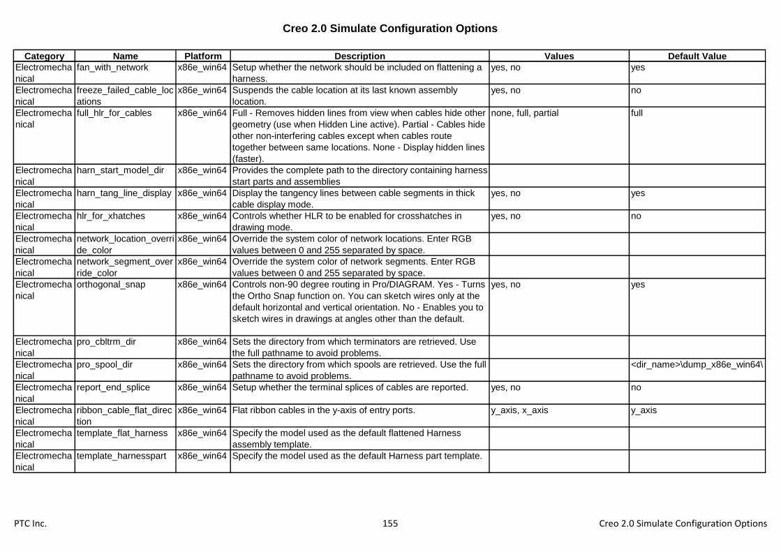
Creo 2.0 Simulate Configuration Options
Category Name Platform Description Values Default Value
Electromecha
nical
fan_with_network x86e_win64 Setup whether the network should be included on flattening a
harness.
yes, no yes
Electromecha
nical
freeze_failed_cable_loc
ations
x86e_win64 Suspends the cable location at its last known assembly
location.
yes, no no
Electromecha
nical
full_hlr_for_cables x86e_win64 Full - Removes hidden lines from view when cables hide other
geometry (use when Hidden Line active). Partial - Cables hide
other non-interfering cables except when cables route
together between same locations. None - Display hidden lines
(faster).
none, full, partial full
Electromecha
nical
harn_start_model_dir x86e_win64 Provides the complete path to the directory containing harness
start parts and assemblies
Electromecha
nical
harn_tang_line_display x86e_win64 Display the tangency lines between cable segments in thick
cable display mode.
yes, no yes
Electromecha
nical
hlr_for_xhatches x86e_win64 Controls whether HLR to be enabled for crosshatches in
drawing mode.
yes, no no
Electromecha
nical
network_location_overri
de_color
x86e_win64 Override the system color of network locations. Enter RGB
values between 0 and 255 separated by space.
Electromecha
nical
network_segment_over
ride_color
x86e_win64 Override the system color of network segments. Enter RGB
values between 0 and 255 separated by space.
Electromecha
nical
orthogonal_snap x86e_win64 Controls non-90 degree routing in Pro/DIAGRAM. Yes - Turns
the Ortho Snap function on. You can sketch wires only at the
default horizontal and vertical orientation. No - Enables you to
sketch wires in drawings at angles other than the default.
yes, no yes
Electromecha
nical
pro_cbltrm_dir x86e_win64 Sets the directory from which terminators are retrieved. Use
the full pathname to avoid problems.
Electromecha
nical
pro_spool_dir x86e_win64 Sets the directory from which spools are retrieved. Use the full
pathname to avoid problems.
<dir_name>\dump_x86e_win64\
Electromecha
nical
report_end_splice x86e_win64 Setup whether the terminal splices of cables are reported. yes, no no
Electromecha
nical
ribbon_cable_flat_direc
tion
x86e_win64 Flat ribbon cables in the y-axis of entry ports. y_axis, x_axis y_axis
Electromecha
nical
template_flat_harness x86e_win64 Specify the model used as the default flattened Harness
assembly template.
Electromecha
nical
template_harnesspart x86e_win64 Specify the model used as the default Harness part template.
PTC Inc. 155 Creo 2.0 Simulate Configuration Options

Creo 2.0 Simulate Configuration Options
Category Name Platform Description Values Default Value
Electromecha
nical
terminator_table_out_u
nicode
x86e_win64 YES - Unicode strings are exported in terminator table files,
NO - Unicode strings are converted to ASCII characters for
terminator table export.
yes, no yes
Electromecha
nical
update_harness_mfg_li
ne_color
x86e_win64 Update cable line color for harness-mfg part created in
release 2000i or earlier.
yes, no no
Electromecha
nical
update_pre_130_harne
ss
x86e_win64 Yes - When a cable is added between two previously laid out
locations in a three-dimensional reference harness, display of
the new cable will update automatically in pre-Release 13
flattened cable models.
yes, no no
Electromecha
nical
update_pre_16_cable_l
ayers
x86e_win64 Yes - Harnesses containing cables routed prior to Release
16.0 will be automatically updated upon retrieval to comply
with new display standards.
yes, no no
Environment accuracy_lower_bound x86e_win64 Enter an accuracy value to override the default lower limit.
The minimum value for relative accuracy is 1E-06.
0.0001
Environment bell x86e_win64 Yes - Turns on the keyboard bell that rings after each prompt.
No - Turns off the keyboard bell. To override this setting use
the Environment dialog box on the Tools menu.
yes, no no
Environment clearance_triangulation x86e_win64 Specifies the quality of surface triangulation used to obtain
initial guess points for clearance and interference calculations.
none, high, medium, low none
Environment clock x86e_win64 Yes - Displays the clock while Creo Parametric is working. yes, no no
Environment clr_print_plus_minus x86e_win64 Sets the display of the system accuracy when calculating
clearances between two parts or surfaces. The default is to
not display the accuracy.
yes, no no
Environment company_name x86e_win64 Used with the export option iges_out_mil_d_28000. To
support MIL-D-28000, your company name is required input
and the system prompts you every time you export through
IGES unless you set the company name in your configuration
file.
Environment default_abs_accuracy x86e_win64 Defines the default absolute part accuracy. 0
Environment display_annotations x86e_win64 Determines whether or not annotations are displayed in 3D
models.
yes, no yes
PTC Inc. 156 Creo 2.0 Simulate Configuration Options

Creo 2.0 Simulate Configuration Options
Category Name Platform Description Values Default Value
Environment display_full_object_pat
h
x86e_win64 Controls the display of the object's full file name (including its
object-type suffix and its version number) and file path in the
window title and Model Info display. Yes - Displays full file
name and file path. No - Displays object name only.
yes, no no
Environment enable_absolute_accur
acy
x86e_win64 Controls display of the ACCURACY menu. Yes - ACCURACY
menu always appears when you choose Accuracy from the
PART SETUP menu. No - The menu appears only if the part
is currently defined with absolute accuracy.
yes, no no
Environment flip_arrow_scale x86e_win64 Sets a scale factor for enlarging the size of the flip arrow that
appears for feature creation direction (default = 1).
1
Environment highlight_geometry x86e_win64 Yes - Items selected in the model tree are highlighted in the
geometry area.
yes, no yes
Environment info_output_format x86e_win64 Setup the default format type for information presentation.
Text - information will be output as simple text. HTML -
information will be output as html data.
text, html html
Environment info_output_mode x86e_win64 Sets default method for presenting information. Both - View
information on screen and write information to file. Screen -
View information on screen only. File - Write information to file
only. Choose - Select method from the INFO OUTPUT menu.
both, choose, screen, file both
Environment mass_property_calculat
e
x86e_win64 Calculate mass properties upon regeneration, upon save or by
user request
automatic, by_request,
check_upon_save
by_request
Environment mathcad_automapping x86e_win64 Toggles Mathcad analysis automapping of variables yes, no no
Environment mdx_collision_num_tria
ngles
x86e_win64 The number of mesh triangles which are used to approximate
model in collision detection.
1000
Environment measure_sig_figures x86e_win64 Sets the number of significant figures displayed as results
when using the Measure dialog box from the Info menu.
6
Environment model_grid_balloon_dis
play
x86e_win64 Controls the display of grid balloons. yes, no yes
Environment model_grid_neg_prefix x86e_win64 Enables you to specify the prefix to use for negative numbers
in the balloon capture of the grid.
-
Environment model_grid_num_dig x86e_win64 Controls the number of decimal places displayed in the
balloon capture. 0 - Only integers display.
PTC Inc. 157 Creo 2.0 Simulate Configuration Options

Creo 2.0 Simulate Configuration Options
Category Name Platform Description Values Default Value
Environment model_grid_spacing x86e_win64 Sets the default model grid spacing. 1.5
Environment model_notes_as_labels x86e_win64 Gives the option to display notes as either full text or as label.
Can also be toggled with environment option "Display Notes
as Names."
yes, no no
Environment model_tree_start x86e_win64 Toggles display of the Model Tree. Yes - Displays the Model
Tree window along with its model. No - Does not display the
Model Tree window.
yes, no yes
Environment modelcheck_enabled x86e_win64 Enable ModelCHECK yes, no yes
Environment prehighlight x86e_win64 Yes - Selectable items beneath the pointer are highlighted
prior to being selected. No - Selectable items beneath the
pointer are not highlighted prior to being selected.
yes, no
Environment prehighlight_tree x86e_win64 Default value for "Preselection Highlighting" option in the
model tree, layer tree and detail tree. When enabled,
selectable items are highlighted prior to being selected in the
tree.
yes, no no
Environment pro_unit_length x86e_win64 Sets the default units for new objects. unit_inch, unit_foot, unit_mm,
unit_cm, unit_m
unit_inch
Environment pro_unit_mass x86e_win64 Sets the default units for mass for new objects. unit_ounce, unit_pound, unit_ton,
unit_gram, unit_kilogram,
unit_tonne
unit_pound
Environment pro_unit_sys x86e_win64 Specifies the default system of units for new models. mks, cgs, mmns, fps, ips,
proe_def, mmks
Environment proe_memory_buffer_s
ize
x86e_win64 Specify the size in megabytes of the memory buffer to be
reserved by Creo Parametric for system out of memory
condition. You must restart Creo Parametric for the change to
take effect.
50
Environment regen_backup_director
y
x86e_win64 Specifies the directory in which the system stores
regen_backup models. (See regen_backup_using_disk.) The
primary default is the current directory, but if that directory is
read-only, the secondary default is the /tmp directory.
Environment regen_backup_using_d
isk
x86e_win64 Specifies whether or not the system backs up the current
model to disk before each regeneration.
yes, no no
Environment save_section_surfaces x86e_win64 Yes - Save section surfaces with models. No - Do not save
section surfaces with models.
yes, no yes
PTC Inc. 158 Creo 2.0 Simulate Configuration Options
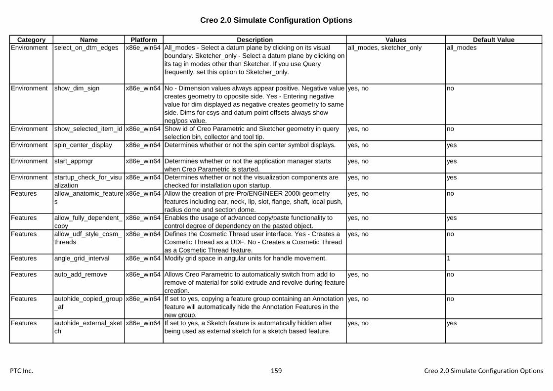
Creo 2.0 Simulate Configuration Options
Category Name Platform Description Values Default Value
Environment select_on_dtm_edges x86e_win64 All_modes - Select a datum plane by clicking on its visual
boundary. Sketcher_only - Select a datum plane by clicking on
its tag in modes other than Sketcher. If you use Query
frequently, set this option to Sketcher_only.
all_modes, sketcher_only all_modes
Environment show_dim_sign x86e_win64 No - Dimension values always appear positive. Negative value
creates geometry to opposite side. Yes - Entering negative
value for dim displayed as negative creates geometry to same
side. Dims for csys and datum point offsets always show
neg/pos value.
yes, no no
Environment show_selected_item_id x86e_win64 Show id of Creo Parametric and Sketcher geometry in query
selection bin, collector and tool tip.
yes, no no
Environment spin_center_display x86e_win64 Determines whether or not the spin center symbol displays. yes, no yes
Environment start_appmgr x86e_win64 Determines whether or not the application manager starts
when Creo Parametric is started.
yes, no yes
Environment startup_check_for_visu
alization
x86e_win64 Determines whether or not the visualization components are
checked for installation upon startup.
yes, no yes
Features allow_anatomic_feature
s
x86e_win64 Allow the creation of pre-Pro/ENGINEER 2000i geometry
features including ear, neck, lip, slot, flange, shaft, local push,
radius dome and section dome.
yes, no no
Features allow_fully_dependent_
copy
x86e_win64 Enables the usage of advanced copy/paste functionality to
control degree of dependency on the pasted object.
yes, no yes
Features allow_udf_style_cosm_
threads
x86e_win64 Defines the Cosmetic Thread user interface. Yes - Creates a
Cosmetic Thread as a UDF. No - Creates a Cosmetic Thread
as a Cosmetic Thread feature.
yes, no no
Features angle_grid_interval x86e_win64 Modify grid space in angular units for handle movement. 1
Features auto_add_remove x86e_win64 Allows Creo Parametric to automatically switch from add to
remove of material for solid extrude and revolve during feature
creation.
yes, no no
Features autohide_copied_group
_af
x86e_win64 If set to yes, copying a feature group containing an Annotation
feature will automatically hide the Annotation Features in the
new group.
yes, no no
Features autohide_external_sket
ch
x86e_win64 If set to yes, a Sketch feature is automatically hidden after
being used as external sketch for a sketch based feature.
yes, no yes
PTC Inc. 159 Creo 2.0 Simulate Configuration Options

Creo 2.0 Simulate Configuration Options
Category Name Platform Description Values Default Value
Features autoround_max_n_chai
ns_per_feat
x86e_win64 Determines the maximum number of edge chains that the
Auto-Round algorithm will attempt to round in each Auto-
Round member
20
Features centimeter_grid_interva
l
x86e_win64 Modify grid space in centimeter units for handle movement. 0.1
Features copy_set_datum_attr x86e_win64 If set to yes, allow to copy set datum associated with datum
features..
yes, no yes
Features default_dep_copy_opti
on
x86e_win64 Sets Full Dependent Copy as a default copy option. full_dep, dep_dim dep_dim
Features display_draggers x86e_win64 Display Dragger for Edit mode. yes, no yes
Features dynamic_preview x86e_win64 Controls the default state of geometry preview within a feature
tool. Attached/Unattached - Dynamic attached/unattached
geometry preview will be enabled. No - Geometry preview will
not be enabled.
no, attached, unattached attached
Features enable_auto_regen x86e_win64 Enable Auto Regeneration for Unified Edit Mode. yes, no yes
Features enable_tapered_extrud
e
x86e_win64 Enables you to add a taper to an extrude feature by displaying
the Add taper check box and the taper degree value box on
the Extrude tab Options tab. yes - The Add taper check box is
displayed. no - The Add taper check box is not displayed.
yes, no yes
Features fail_unattached_feature x86e_win64 Handles unattached protrusion and cuts, when retrieving pre-
Release 15 models. Yes - When a part is retrieved, the
system fails an unattached protrusion or cut. No - When a part
is retrieved, the system does not fail an unattached protrusion
or cut.
yes, no no
Features feature_create_auto_b
egin
x86e_win64 In feature creation, determines whether or not the Define
button is automatically activated when you open the dialog
box. Yes - Button is activated automatically. No - You select
the button.
yes, no no
Features feature_create_auto_o
k
x86e_win64 In feature creation, determines whether or not the system
activates the dialog box OK button automatically when the last
required element is defined. Yes - Button is activated
automatically. No - You select the button.
yes, no no
Features feature_type_default x86e_win64 It sets the solid or surface default type for feature creation.
The Advanced option sets the default type for Extrude and
Revolve to solid, and all others to Surface.
solid, advanced, surface solid
PTC Inc. 160 Creo 2.0 Simulate Configuration Options

Creo 2.0 Simulate Configuration Options
Category Name Platform Description Values Default Value
Features foot_grid_interval x86e_win64 Modify grid space in foot units for handle movement. 0.083333
Features hole_diameter_override x86e_win64 No- Uses hole-table-driven standard hole diameter value. Yes -
Allows specifying the drilled hole value instead of the standard
value.
yes, no no
Features hole_file_resolution x86e_win64 Specify Hole tool to use external hole parameter (.hol) files. replace_with_external,
use_internal
replace_with_external
Features hole_parameter_file_pa
th
x86e_win64 Specifies the directory path for a standard screw-size
parameters (.hol) file to be loaded from disk. Use the full path
name to avoid problems.
Features inch_grid_interval x86e_win64 Modify grid space in inch units for handle movement. 0.03125
Features keep_info_datums x86e_win64 Sets the initial state of how the system treats datums and
features created at run time.
yes, no yes
Features max_regen_time_attac
h_preview
x86e_win64 Sets the maximum regeneration time for the dynamic attached
preview.
0.5
Features merge_type x86e_win64 Sets the default merge type surface merge operations. join, intersect intersect
Features meter_grid_interval x86e_win64 Modify grid space in meter units for handle movement. 0.001
Features millimeter_grid_interval x86e_win64 Modify grid space in millimeter units for handle movement. 0.1
Features pro_group_dir x86e_win64 Sets the default directory for the user-defined feature (UDF)
library. If not specified, your current working directory is the
default. Use the full pathname to avoid problems.
Features ratio_grid_interval x86e_win64 Modify grid space in percentage units for handle movement. 0.05
Features show_geom_checks_o
n_creation
x86e_win64 Yes - The SHOW ERRORS menu appears at the end of
feature creation when the feature being created has Geometry
Checks.
yes, no no
Features troubleshooter_show_i
nfo_gcheck
x86e_win64 When set to Yes this option will add a "Show info items" filter
to the View panel in the Troubleshooter.
yes, no no
Features udf_af_name_postfix x86e_win64 If set to yes, a sequential number will be appended to the
name of annotation feature in group from Copy and UDF
placement.
yes, no yes
Features user_defined_grid_inter
val
x86e_win64 Modify grid space in user defined length units for handle
movement.
0.5
PTC Inc. 161 Creo 2.0 Simulate Configuration Options

Creo 2.0 Simulate Configuration Options
Category Name Platform Description Values Default Value
File Storage
& Retrieval
analysis_crt_tmp_file_o
n_regen
x86e_win64 Determines whether regeneration of analysis features
creates/updates tmp files
yes, no yes
File Storage
& Retrieval
browser_favorite x86e_win64 Specifies the directories visible in the file browser for quick
navigation. Use the full path to avoid problems.
File Storage
& Retrieval
compress_output_files x86e_win64 Yes - Stores object files in a compressed format. Note:
Compressed files are usually smaller, buy may be larger, than
uncompressed files. Compressed files are slower to read and
to write to.
yes, no no
File Storage
& Retrieval
dir_cache_max x86e_win64 Specify the maximum number of directories to cache. Larger
values can speed up file access, but use more memory.
256
File Storage
& Retrieval
disable_search_path_c
heck
x86e_win64 Controls whether the search path is checked for name
conflicts when creating, renaming, or copying models. Name
conflicts should be avoided because different models with the
same name cannot be together in session.
yes, no no
File Storage
& Retrieval
excel_analysis_director
y
x86e_win64 Sets the default directory for the MS Excel files to be used for
Excel analysis calculations. Use the full pathname to avoid
problems.
File Storage
& Retrieval
excel_family_table_kee
p_file
x86e_win64 Yes - in case of editing family table with excel, if saved excel
file exist , will always update it.
yes, no no
File Storage
& Retrieval
exec_prog_on_assem_
retr
x86e_win64 Execute pro/program for models during assembly retrieval. yes, no no
File Storage
& Retrieval
external_analysis_direc
tory
x86e_win64 Sets the default directory for the files to be used by External
Analysis calculations. Use the full pathname to avoid
problems.
File Storage
& Retrieval
file_open_default_folde
r
x86e_win64 Sets default dir for File>Open. Working_directory - Search
working directory. In_session - Search objects in session.
Pro_library - Use only if Pro/LIBRARY is installed. Workspace -
Use only with Pro/INTRALINK. Commonspace - Use only with
Pro/INTRALINK.
default, working_directory,
in_session, pro_library,
my_documents, desktop
File Storage
& Retrieval
file_open_default_view x86e_win64 Specify the initial Views setting as List or Details in the File
dialog boxes.
list, details list
File Storage
& Retrieval
file_open_preview_defa
ult
x86e_win64 Controls whether the preview area is expanded by default
when the file open dialog or local file browser is displayed.
expanded, collapsed collapsed
File Storage
& Retrieval
file_open_preview_dela
y
x86e_win64 The delay before a file selection is previewed, in tenths of a
second.
PTC Inc. 162 Creo 2.0 Simulate Configuration Options

Creo 2.0 Simulate Configuration Options
Category Name Platform Description Values Default Value
File Storage
& Retrieval
force_new_file_options
_dialog
x86e_win64 Force the use of the New File Options dialog. yes, no no
File Storage
& Retrieval
generate_viewable_on
_save
x86e_win64 Controls whether updated Creo View .edz files are
automatically exported every time a model is saved.
yes, no no
File Storage
& Retrieval
geometry_analysis_col
or_scheme
x86e_win64 Specifies the location of the geometry analysis color scheme
file.
File Storage
& Retrieval
instance_search_exha
ustive
x86e_win64 Specifies extent of instance search. Yes - Include file type
when entering instance name in File>Open: type in input
panel (e.g. inst_name.prt) or select in drop-down list. If no .idx
files are found, only working dir is searched; each generic is
not.
yes, no no
File Storage
& Retrieval
lang_propagate x86e_win64 Specifies language storage options. The option provides
flexibility for objects that use a different language than the
current
yes, no yes
File Storage
& Retrieval
mathcad_analysis_dire
ctory
x86e_win64 Sets the default directory for the Mathcad files to be used for
Mathcad analysis calculations. Use the full pathname to avoid
problems.
File Storage
& Retrieval
menu_show_instances x86e_win64 Determines whether instance names listed in instance index
files appear in file lists.
yes, no yes
File Storage
& Retrieval
mfg_start_model_dir x86e_win64 Provides the complete path to the directory containing mfg
start assemblies.
File Storage
& Retrieval
model_rename_templat
e
x86e_win64 Sets the default renaming convention for copied assemblies.
The default new name is the old name appended with an
underscore (_). Adding a template such as [*a1*=*b1*]
changes every occurrence of a1 to b1 (e.g.
TOP_A1_BRACKET copies to TOP_B1_BRACKET).
File Storage
& Retrieval
modified_objs_in_new_
dir
x86e_win64 Yes- During Save a Copy operations, any modified object that
is not renamed will be saved in the new directory. No- Any
modified object that is not renamed will be saved to the
retrieval directory.
yes, no no
File Storage
& Retrieval
open_draw_simp_rep_
by_default
x86e_win64 Set to "Yes" to always invoke the open rep dialog when
opening a drawing.
yes, no no
File Storage
& Retrieval
open_simplified_rep_by
_default
x86e_win64 Retrieves a model in a specified representation. Yes - uses
Open Rep dialog. No - retrieves the Master representation.
Specified Name - retrieves the model in the specified
representation name if it exists or the Default representation.
no
PTC Inc. 163 Creo 2.0 Simulate Configuration Options

Creo 2.0 Simulate Configuration Options
Category Name Platform Description Values Default Value
File Storage
& Retrieval
override_store_back x86e_win64 Forces the storage of objects retrieved from other directories
to the current working directory.
yes, no no
File Storage
& Retrieval
placement_rep_by_def
ault
x86e_win64 Retrieves the assembled component in a specified
representation. None - retrieves the representation specified
in configuration option open_simplified_rep_by_default.
none
File Storage
& Retrieval
preferred_save_as_typ
e
x86e_win64 Allows customizing the order of the Type selections found
under File ->Save A Copy.
File Storage
& Retrieval
pro_crosshatch_dir x86e_win64 Specifies a default directory for your cross-hatch library in
which you can save cross-hatching patterns for later retrieval.
Its value is the full path name of the default directory.
File Storage
& Retrieval
pro_font_dir x86e_win64 Sets the default font directory (Creo Parametric will load all
fonts in this directory into the drawing regardless of the
contents of the system and working directories).
<creo_loadpoint>\text\fonts\
File Storage
& Retrieval
pro_library_dir x86e_win64 Sets the default directory for the Creo Parametric libraries (or
any libraries you have built containing the proper index menu
files). Use the full pathname to avoid problems.
File Storage
& Retrieval
pro_material_dir x86e_win64 Sets the default directory for the part material library. Use the
full pathname to avoid problems.
File Storage
& Retrieval
pro_surface_finish_dir x86e_win64 Sets the default directory for your user-defined surface finish
symbols. Use the full pathname to avoid problems.
<creo_loadpoint>\symbols\surffi
ns\
File Storage
& Retrieval
prompt_on_erase_not_
disp
x86e_win64 Specifies whether or not to display a prompt allowing you to
save your undisplayed objects. This option is used in
conjunction with the Erase > Not Displayed command on the
File menu.
yes, no no
File Storage
& Retrieval
propagate_change_to_
parents
x86e_win64 When saving objects with option save_objects set to Changed
or Changed_and_specified, Creo Parametric verifies which
models are. Yes - Any model that is a parent of a changed
model is considered to be a changed model when determining
what to save.
yes, no no
File Storage
& Retrieval
read_famtab_file_on_r
etrieve
x86e_win64 No - Ignores filename.ptd. Yes - Creates and saves
filename.ptd and uses that file when retrieving the generic.
yes, no no
PTC Inc. 164 Creo 2.0 Simulate Configuration Options

Creo 2.0 Simulate Configuration Options
Category Name Platform Description Values Default Value
File Storage
& Retrieval
regen_simp_retrieve x86e_win64 Regenerate the assembly when retrieving an assembly
simplified representation. Yes - Regenerates the assembly on
retreival. No - The assembly is not regenerated on retrieval.
yes, no no
File Storage
& Retrieval
rename_drawings_with
_object
x86e_win64 Controls whether the system copies associated drawings
automatically with parts and assemblies.
none, both, part, assem none
File Storage
& Retrieval
retain_display_memory x86e_win64 Determines if the display of an object currently on the screen
is kept in memory when you quit the window. Doing so (yes)
makes the retrieval of objects in memory faster.
yes, no yes
File Storage
& Retrieval
retrieve_data_sharing_r
ef_parts
x86e_win64 Automatic reference parts retrieval for dependent data sharing
features.
yes, no, ignore_missing no
File Storage
& Retrieval
save_clipped_view x86e_win64 Yes - clipping status is saved with model. No - clipping status
is not saved.
yes, no no
File Storage
& Retrieval
save_dialog_for_existin
g_models
x86e_win64 Controls whether the Save dialog is shown for models whose
storage location is already known.
yes, no yes
File Storage
& Retrieval
save_instance_acceler
ator
x86e_win64 With family tables of solid parts, determines saving instance
accelerators. None - Accelerator files not used. Explicit - Save
when instance is explicitly saved. Saved objects - Save when
objects were modified. Always - Always save.
none, explicit, always,
saved_objects
saved_objects
File Storage
& Retrieval
save_model_display x86e_win64 Sets amount of graphical data stored. Wireframe - Wireframe
data. Shading_high - Most detail (shaded). Shading_low -
Least detail (shaded). Shading_lod - Detail determined by
View Performance dialog (shaded).
wireframe, shading_low,
shading_high, shading_lod
shading_lod
File Storage
& Retrieval
save_object_in_current x86e_win64 Use with the override_store_back option. Yes - Objects
retrieved from a directory where you do not have write
permission will be stored in the current directory. No - These
objects are not saved at all.
yes, no no
File Storage
& Retrieval
save_objects x86e_win64 Determines when an object and its dependent objects (such
as a part used in an assembly) are stored.
all, changed,
changed_and_specified,
changed_and_updated
changed_and_specified
File Storage
& Retrieval
saving_model_thumbn
ails
x86e_win64 Enables saving of model thumbnails. yes, no yes
PTC Inc. 165 Creo 2.0 Simulate Configuration Options

Creo 2.0 Simulate Configuration Options
Category Name Platform Description Values Default Value
File Storage
& Retrieval
search_path x86e_win64 Specifies list of directories to search (in order) for object/file
retrieval. These directories, the working directory, and
directories in search.pro file (refer to search_path_file) are
Creo Parametric's search path. Use full path name to avoid
problems.
File Storage
& Retrieval
search_path_file x86e_win64 Specifies path to text file search.pro (a list of directory path
names). The directories listed in search.pro, the working
directory, and directories specified by search_path are Creo
Parametric's search path. Use full path name to avoid
problems.
File Storage
& Retrieval
set_model_types_to_sa
ve
x86e_win64 Determines which model types are used in the Save Changed
command. The format is a list of extensions separated by
spaces.
asm prt drw sec mfg gph ipf
cem
File Storage
& Retrieval
start_model_dir x86e_win64 Provides the complete path to the directory containing start
parts and assemblies.
File Storage
& Retrieval
template_designasm x86e_win64 Specifies the designated template assembly. Use full path to
avoid problems.
inlbs_asm_design.asm
File Storage
& Retrieval
template_drawing x86e_win64 Specify the drawing used as the default drawing template. c_drawing.drw
File Storage
& Retrieval
template_ecadasm x86e_win64 Specify the model used as the default ECAD assembly
template.
File Storage
& Retrieval
template_ecadpart x86e_win64 Specify the model used as the default ECAD part template.
File Storage
& Retrieval
template_mfgcast x86e_win64 Specify the model used as the default manufacturing cast
template.
inlbs_mfg_cast.asm
File Storage
& Retrieval
template_mfgcmm x86e_win64 Specify the model used as the default manufacturing cmm
template.
inlbs_mfg_cmm.asm
File Storage
& Retrieval
template_mfgemo x86e_win64 Specify the model used as the default manufacturing expert
machinist template.
inlbs_mfg_emo.asm
File Storage
& Retrieval
template_mfgmold x86e_win64 Specify the model used as the default manufacturing mold
template.
inlbs_mfg_mold.asm
File Storage
& Retrieval
template_mfgnc x86e_win64 Specify the model used as the default manufacturing
assembly template.
inlbs_mfg_nc.asm
File Storage
& Retrieval
template_module x86e_win64 Specifies the default module template file. Use full pathname
to avoid problems.
inlbs_asm_module.asm
File Storage
& Retrieval
template_mold_layout x86e_win64 Specify the mold layout assembly used as a default template. inlbs_mold_lay.asm
PTC Inc. 166 Creo 2.0 Simulate Configuration Options
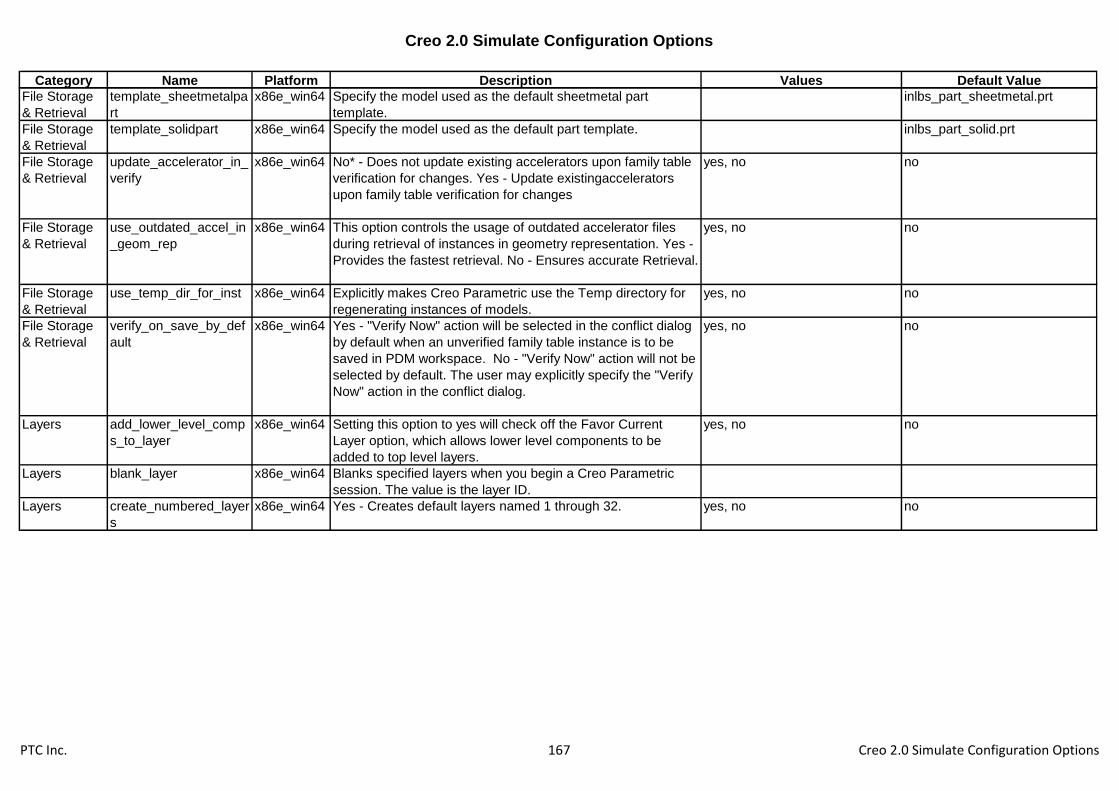
Creo 2.0 Simulate Configuration Options
Category Name Platform Description Values Default Value
File Storage
& Retrieval
template_sheetmetalpa
rt
x86e_win64 Specify the model used as the default sheetmetal part
template.
inlbs_part_sheetmetal.prt
File Storage
& Retrieval
template_solidpart x86e_win64 Specify the model used as the default part template. inlbs_part_solid.prt
File Storage
& Retrieval
update_accelerator_in_
verify
x86e_win64 No* - Does not update existing accelerators upon family table
verification for changes. Yes - Update existingaccelerators
upon family table verification for changes
yes, no no
File Storage
& Retrieval
use_outdated_accel_in
_geom_rep
x86e_win64 This option controls the usage of outdated accelerator files
during retrieval of instances in geometry representation. Yes -
Provides the fastest retrieval. No - Ensures accurate Retrieval.
yes, no no
File Storage
& Retrieval
use_temp_dir_for_inst x86e_win64 Explicitly makes Creo Parametric use the Temp directory for
regenerating instances of models.
yes, no no
File Storage
& Retrieval
verify_on_save_by_def
ault
x86e_win64 Yes - "Verify Now" action will be selected in the conflict dialog
by default when an unverified family table instance is to be
saved in PDM workspace. No - "Verify Now" action will not be
selected by default. The user may explicitly specify the "Verify
Now" action in the conflict dialog.
yes, no no
Layers add_lower_level_comp
s_to_layer
x86e_win64 Setting this option to yes will check off the Favor Current
Layer option, which allows lower level components to be
added to top level layers.
yes, no no
Layers blank_layer x86e_win64 Blanks specified layers when you begin a Creo Parametric
session. The value is the layer ID.
Layers create_numbered_layer
s
x86e_win64 Yes - Creates default layers named 1 through 32. yes, no no
PTC Inc. 167 Creo 2.0 Simulate Configuration Options

Creo 2.0 Simulate Configuration Options
Category Name Platform Description Values Default Value
Layers def_layer x86e_win64 Specifies default layer names for different types of items. The
first value string is the layer type. The second value string is
the layer name.
layer_assem_member,
layer_assy_cut_feat, layer_axis,
layer_chamfer_feat,
layer_comp_design_model,
layer_comp_fixture,
layer_comp_workpiece,
layer_copy_geom_feat,
layer_corn_chamf_feat,
layer_cosm_round_feat,
layer_cosm_sketch, layer_csys,
layer_curve, layer_curve_ent,
layer_cut_feat, layer_datum,
layer_datum_plane,
layer_datum_point,
layer_detail_item,
layer_dgm_conn_comp,
layer_dgm_highway,
layer_dgm_rail,
PTC Inc. 168 Creo 2.0 Simulate Configuration Options
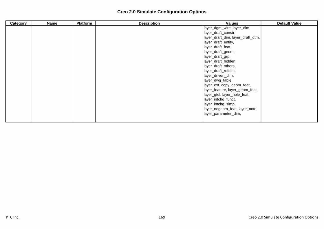
Creo 2.0 Simulate Configuration Options
Category Name Platform Description Values Default Value
layer_dgm_wire, layer_dim,
layer_draft_constr,
layer_draft_dim, layer_draft_dtm,
layer_draft_entity,
layer_draft_feat,
layer_draft_geom,
layer_draft_grp,
layer_draft_hidden,
layer_draft_others,
layer_draft_refdim,
layer_driven_dim,
layer_dwg_table,
layer_ext_copy_geom_feat,
layer_feature, layer_geom_feat,
layer_gtol, layer_hole_feat,
layer_intchg_funct,
layer_intchg_simp,
layer_nogeom_feat, layer_note,
layer_parameter_dim,
PTC Inc. 169 Creo 2.0 Simulate Configuration Options

Creo 2.0 Simulate Configuration Options
Category Name Platform Description Values Default Value
layer_part_refdim, layer_point,
layer_protrusion_feat, layer_quilt,
layer_refdim, layer_ribbon_feat,
layer_rib_feat, layer_round_feat,
layer_sfin, layer_shell_feat,
layer_skeleton_model,
layer_slot_feat, layer_snap_line,
layer_solid_geom, layer_surface,
layer_symbol, layer_thread_feat,
layer_trim_line_feat,
layer_weld_feat,
layer_all_detail_items,
layer_annotation_element,
layer_axis_ent, layer_csys_ent,
layer_set_datum_tag,
layer_3d_items,
layer_ae_driving_dim,
layer_draft_xsec,
layer_hole_thread
Layers default_layer_model x86e_win64 Name of the model which is used to drive rule-based layer
placement of new items in all models of the same type in
session.
Layers display_layer x86e_win64 This causes the specified layers to display when you begin a
Creo Parametric session. The variable "value" is the layer Id.
Layers floating_layer_tree x86e_win64 Set to yes if user wants to see a layer tree dialog separated
from navigator.
yes, no no
Layers highlight_layer_items x86e_win64 Yes - Items selected in the layer tree are highlighted in the
geometry area.
yes, no yes
Layers layer_item_highlight_li
mit
x86e_win64 Set the upper limit of items in a layer for highlighting. If items
in a layer exceeds this number, highlighting will not occur.
500
PTC Inc. 170 Creo 2.0 Simulate Configuration Options

Creo 2.0 Simulate Configuration Options
Category Name Platform Description Values Default Value
Layers save_display_status_in
_submodel
x86e_win64 If set to no, the top level assembly will store sub model layer
display status, allowing lower level display status to be stored
without having to save the sub models.
yes, no yes
Manufacturin
g
allow_mfg_in_assem_
mode
x86e_win64 Allows a manufacturing model to be opened in assembly
mode from the file open dialog.
yes, no no
Manufacturin
g
assy_mfg_open_mode x86e_win64 No Default Application set for opening Assembly NC Models. mfg, process, feature, any_mode any_mode
Manufacturin
g
autodrill_udf_dir x86e_win64 Storage directory for holemaking MUDF's that are used by
Pro/NC Auto-drilling functionality
Manufacturin
g
autodrilling_config_filen
ame
x86e_win64 Retrieve automatically and load the configuration file for the
auto-drilling table.
autodrilling
Manufacturin
g
autodrilling_holestyle_p
aram
x86e_win64 Parameter name included in hole features of a manufacturing
reference model. The parameter value identifies the MUDF
for holemaking that is automatically applied in Pro/NC to drill
these holes.
Manufacturin
g
campost_dir x86e_win64 Specifies the CAM-Post load point directory to enable you to
directly set-up the post-processors and generate MCD files.
Manufacturin
g
chk_part_surfs_profpoc
k
x86e_win64 Yes - Includes all reference part surfaces as check surfaces
for profiling and pocketing NC sequences.
yes, no no
Manufacturin
g
cl_arrow_scale x86e_win64 Enables you to control the size of the tool path arrow for
contouring NC sequences. 0 - The arrow does not display.
Any other value - The arrow scales accordingly.
1
Manufacturin
g
cl_rotate_sign_conventi
on
x86e_win64 TOOL or TABLE - defines ROTATE sign direction convention
based with respect to either rotation table or cutting tool.
table, tool table
Manufacturin
g
cmm_custom_tool_par
am_file
x86e_win64 Defines the file that contains the user-defined tool parameters'
list.
Manufacturin
g
display_mfg_icon_for_
mfg_assy
x86e_win64 Yes- Display manufacturing icon for manufacturing assembly
files in Open/Save dialogs. No- the manufacturing assembly
files have assembly icons.
yes, no no
Manufacturin
g
gpostpp_dir x86e_win64 Specifies the directory containing the post processor files to
be used by Pro/NCPOST (GPOST).
Manufacturin
g
mfg_auto_ref_mfg_tem
plate
x86e_win64 Enable/Disable auto referencing for Manufacturing template yes, no no
PTC Inc. 171 Creo 2.0 Simulate Configuration Options

Creo 2.0 Simulate Configuration Options
Category Name Platform Description Values Default Value
Manufacturin
g
mfg_auto_ref_prt_as_c
hk_srf
x86e_win64 Yes - In 3, 4, and 5 axis contour and conventional mill
sequences, the entire reference part is selected as check
surfaces by default when computing the NC sequence
toolpath for those sequences. No - You select the check
surfaces.
yes, no yes
Manufacturin
g
mfg_auto_retract_clear
_dist
x86e_win64 Specifies distance between automatically created retract plane
and step coordinate system. Will be applied to the new steps
created in process manager if operation retract cannot be
used.
0
Manufacturin
g
mfg_custom_tool_para
m_file
x86e_win64 Defines the file that contains the user-defined tool parameters'
list.
Manufacturin
g
mfg_customize_dialog x86e_win64 Yes - Uses the new customize dialog box for customizing NC
sequences. No - Uses the Release 19.0 menus.
yes, no yes
Manufacturin
g
mfg_cutline_save_mes
h
x86e_win64 Yes - Save / Retrieve Mesh for subsequent cutline
recalculations, No - New Mesh will be computed for each
cutline recalculations.
yes, no yes
Manufacturin
g
mfg_ijk_num_digits x86e_win64 Sets the number of digits for i, j, k data points in a CL data file. 10
Manufacturin
g
mfg_info_location x86e_win64 top left /bottom right -Position of the mfg. Info dialog box. top_left, bottom_right top_left
Manufacturin
g
mfg_modal_command_
file
x86e_win64 Enables you to make some of the APTn index topics modal,
which means that you repeatedly get a list of major keywords
corresponding to this topic upon completing a command line.
Manufacturin
g
mfg_param_auto_copy
_from_tool
x86e_win64 Do not copy any parameter of the tool to the sequence
parameter tree.
all, none, misc, cutting none
Manufacturin
g
mfg_process_print_dir x86e_win64 Specifies the directory where Mfg Process html page get
stored. Use the full pathname to avoid problems.
Manufacturin
g
mfg_process_sync_by_
default
x86e_win64 Specifies whether all steps created in the Process Manager
get automatically synchronized with features in the Pro/NC
assembly. You can change steps later in the dialog box open
during the session.
yes, no yes
Manufacturin
g
mfg_process_table_set
up_dir
x86e_win64 Specifies the directory where Mfg Process Table settings get
stored. Use the full pathname to avoid problems.
Manufacturin
g
mfg_process_template
_dir
x86e_win64 Specifies the directory where Mfg Process Templates get
stored. Use the full pathname to avoid problems.
PTC Inc. 172 Creo 2.0 Simulate Configuration Options

Creo 2.0 Simulate Configuration Options
Category Name Platform Description Values Default Value
Manufacturin
g
mfg_setup_dir x86e_win64 Specifies the directory which contains all manufacturing
related setup files for the current session.
Manufacturin
g
mfg_stock_display_sho
w_default
x86e_win64 yes, no no
Manufacturin
g
mfg_template_dir x86e_win64 Specifies the storage directory for NC templates. Specify full
path to avoid problems. NC templates are used in Expert
Machinist. Templates store the recipe for a toolpath as the
method of tool retrieval.
Manufacturin
g
mfg_tool_dialog_setup
_file
x86e_win64 Specifies the XML based file to setup Tool Dialog.
Manufacturin
g
mfg_udf_info_setup_fil
e
x86e_win64 Specify name and path of the file containing udf and mfg
criteria values .
Manufacturin
g
mfg_workpiece_transp
arency
x86e_win64 Controls the workpiece transparency in shaded model display.
You can change the value in the range between 0.1 and 1.
The bigger the value, the more transparent the workpiece.
The default value is 0.5.
0.67
Manufacturin
g
mfg_xyz_num_digits x86e_win64 Sets the number of digits for x, y, z data points in a CL data
file.
10
Manufacturin
g
nc_autodoc_param_dir x86e_win64 Location of the setup file that describes which process
parameters are included in the parameter table.
Manufacturin
g
nc_autodoc_report_dir x86e_win64 Location for storing the report and images generated by the
shop floor documentation tool.
Manufacturin
g
nc_autodoc_setup_dir x86e_win64 Location for documentation setup files that describe which
process parameters are included in the parameter table.
Manufacturin
g
nc_autodoc_template_
dir
x86e_win64 Location of the style sheet and default images used for shop
floor documentation.
Manufacturin
g
nccheck_type x86e_win64 Vericut will be used for NC material removal simulation. vericut, nccheck vericut
Manufacturin
g
ncl_file_extension x86e_win64 Sets the default file extension for Pro/MFG CL data files. Enter
the file extension only (without the preceding "."). For
example, apt produces filename.apt.
ncl
Manufacturin
g
ncmdl_bar_stock_part_
path
x86e_win64 Sets path for storage and retrieval of stock instances for
creating workpiece in NC Model. Specify full path, including
part name, to avoid problems.
<creo_loadpoint>\text\ncmdl_da
ta\ncmdl_bar.prt
Manufacturin
g
ncmdl_billet_stock_part
_path
x86e_win64 Sets path for storage and retrieval of stock instances for
creating workpiece in NC Model. Specify full path, including
part name, to avoid problems.
<creo_loadpoint>\text\ncmdl_da
ta\ncmdl_billet.prt
PTC Inc. 173 Creo 2.0 Simulate Configuration Options

Creo 2.0 Simulate Configuration Options
Category Name Platform Description Values Default Value
Manufacturin
g
ncpost_type x86e_win64 Set to GPOST to access the default post processor supplied
with Pro/NCPOST.
gpost, ncpost
Manufacturin
g
ncseq_outbound_curve x86e_win64 Yes - Create out bound curve. yes
Manufacturin
g
new_turn_scan_type x86e_win64 Allows to use New turn scan types for Turning NC sequences. yes, no yes
Manufacturin
g
pro_mdb_dir x86e_win64 Sets the default directory for the Machinability Database
(MDB) files. Use the full pathname to avoid problems.
Manufacturin
g
pro_mf_cl_dir x86e_win64 Sets the default directory for the manufacturing CL data
files.Use the full pathname to avoid problems.
Manufacturin
g
pro_mf_clamp_dir x86e_win64 Specifies the directory where the manufacturing clamps can
be found.
Manufacturin
g
pro_mf_param_dir x86e_win64 Sets the default directory for the manufacturing parameter
files. Use the full pathname to avoid problems.
Manufacturin
g
pro_mf_tape_dir x86e_win64 Sets the default directory for the manufacturing TAPE data
files.Use the full pathname to avoid problems.
Manufacturin
g
pro_mf_tprm_dir x86e_win64 Sets the default directory for the manufacturing tool files. Use
the full pathname to avoid problems.
Manufacturin
g
pro_mf_workcell_dir x86e_win64 Sets the default directory for the manufacturing workcell files.
Use the full pathname to avoid problems.
Manufacturin
g
pro_mfg_cmdsyn_dir x86e_win64 Sets the default directory for the syntax menu files in
Pro/MFG. Use the full pathname to avoid problems.
Manufacturin
g
profile_output_utils x86e_win64 Affects CL-Data output for profile milling sequences. Yes -
Sequence parameter output_point is available with options: tip
- Toolpath is output with respect to the tool center; on_profile -
Toolpath is output with respect to the profile of the tool.
yes, no no
Manufacturin
g
proncpost_dbf x86e_win64 Enter directory path to NCPost database file.
Manufacturin
g
prorembatch_queue_m
anager
x86e_win64 Enables toolpath computation on a separate host machine.
Required values are Processor name, Remote machine's
hostname, Type of transport (always 0), RPC processor
number (same as that of remote processor), Version of queue
manager.
Manufacturin
g
ptncpost_dbf x86e_win64 Enter directory path to NCPost database file.
PTC Inc. 174 Creo 2.0 Simulate Configuration Options
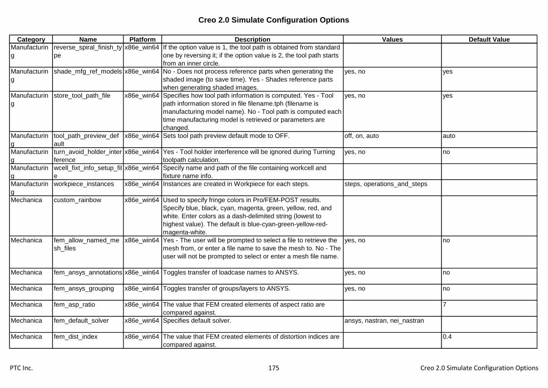
Creo 2.0 Simulate Configuration Options
Category Name Platform Description Values Default Value
Manufacturin
g
reverse_spiral_finish_ty
pe
x86e_win64 If the option value is 1, the tool path is obtained from standard
one by reversing it; if the option value is 2, the tool path starts
from an inner circle.
Manufacturin
g
shade_mfg_ref_models x86e_win64 No - Does not process reference parts when generating the
shaded image (to save time). Yes - Shades reference parts
when generating shaded images.
yes, no yes
Manufacturin
g
store_tool_path_file x86e_win64 Specifies how tool path information is computed. Yes - Tool
path information stored in file filename.tph (filename is
manufacturing model name). No - Tool path is computed each
time manufacturing model is retrieved or parameters are
changed.
yes, no yes
Manufacturin
g
tool_path_preview_def
ault
x86e_win64 Sets tool path preview default mode to OFF. off, on, auto auto
Manufacturin
g
turn_avoid_holder_inter
ference
x86e_win64 Yes - Tool holder interference will be ignored during Turning
toolpath calculation.
yes, no no
Manufacturin
g
wcell_fixt_info_setup_fil
e
x86e_win64 Specify name and path of the file containing workcell and
fixture name info.
Manufacturin
g
workpiece_instances x86e_win64 Instances are created in Workpiece for each steps. steps, operations_and_steps
Mechanica custom_rainbow x86e_win64 Used to specify fringe colors in Pro/FEM-POST results.
Specify blue, black, cyan, magenta, green, yellow, red, and
white. Enter colors as a dash-delimited string (lowest to
highest value). The default is blue-cyan-green-yellow-red-
magenta-white.
Mechanica fem_allow_named_me
sh_files
x86e_win64 Yes - The user will be prompted to select a file to retrieve the
mesh from, or enter a file name to save the mesh to. No - The
user will not be prompted to select or enter a mesh file name.
yes, no no
Mechanica fem_ansys_annotations x86e_win64 Toggles transfer of loadcase names to ANSYS. yes, no no
Mechanica fem_ansys_grouping x86e_win64 Toggles transfer of groups/layers to ANSYS. yes, no no
Mechanica fem_asp_ratio x86e_win64 The value that FEM created elements of aspect ratio are
compared against.
7
Mechanica fem_default_solver x86e_win64 Specifies default solver. ansys, nastran, nei_nastran
Mechanica fem_dist_index x86e_win64 The value that FEM created elements of distortion indices are
compared against.
0.4
PTC Inc. 175 Creo 2.0 Simulate Configuration Options
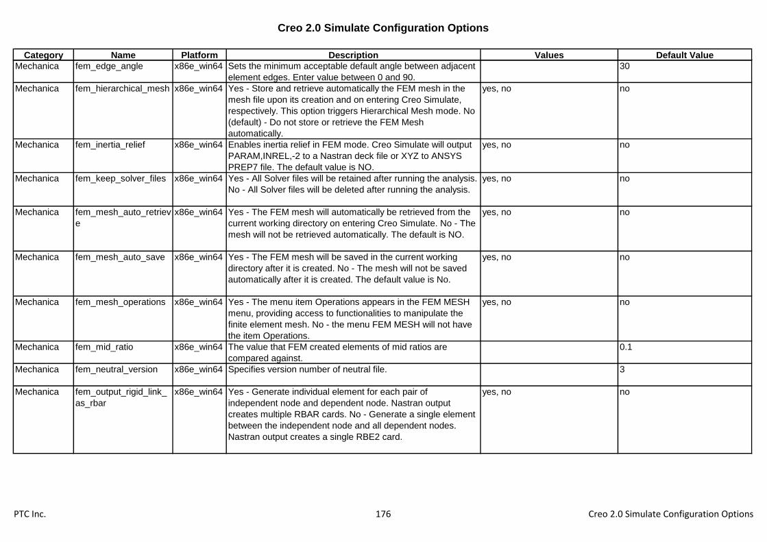
Creo 2.0 Simulate Configuration Options
Category Name Platform Description Values Default Value
Mechanica fem_edge_angle x86e_win64 Sets the minimum acceptable default angle between adjacent
element edges. Enter value between 0 and 90.
30
Mechanica fem_hierarchical_mesh x86e_win64 Yes - Store and retrieve automatically the FEM mesh in the
mesh file upon its creation and on entering Creo Simulate,
respectively. This option triggers Hierarchical Mesh mode. No
(default) - Do not store or retrieve the FEM Mesh
automatically.
yes, no no
Mechanica fem_inertia_relief x86e_win64 Enables inertia relief in FEM mode. Creo Simulate will output
PARAM,INREL,-2 to a Nastran deck file or XYZ to ANSYS
PREP7 file. The default value is NO.
yes, no no
Mechanica fem_keep_solver_files x86e_win64 Yes - All Solver files will be retained after running the analysis.
No - All Solver files will be deleted after running the analysis.
yes, no no
Mechanica fem_mesh_auto_retriev
e
x86e_win64 Yes - The FEM mesh will automatically be retrieved from the
current working directory on entering Creo Simulate. No - The
mesh will not be retrieved automatically. The default is NO.
yes, no no
Mechanica fem_mesh_auto_save x86e_win64 Yes - The FEM mesh will be saved in the current working
directory after it is created. No - The mesh will not be saved
automatically after it is created. The default value is No.
yes, no no
Mechanica fem_mesh_operations x86e_win64 Yes - The menu item Operations appears in the FEM MESH
menu, providing access to functionalities to manipulate the
finite element mesh. No - the menu FEM MESH will not have
the item Operations.
yes, no no
Mechanica fem_mid_ratio x86e_win64 The value that FEM created elements of mid ratios are
compared against.
0.1
Mechanica fem_neutral_version x86e_win64 Specifies version number of neutral file. 3
Mechanica fem_output_rigid_link_
as_rbar
x86e_win64 Yes - Generate individual element for each pair of
independent node and dependent node. Nastran output
creates multiple RBAR cards. No - Generate a single element
between the independent node and all dependent nodes.
Nastran output creates a single RBE2 card.
yes, no no
PTC Inc. 176 Creo 2.0 Simulate Configuration Options

Creo 2.0 Simulate Configuration Options
Category Name Platform Description Values Default Value
Mechanica fem_preserve_mesh x86e_win64 Yes - Issue a warning whenever the current operation
invalidates the existing FEM mesh. No (default) - Erase the
mesh without notification when it becomes incompatible with
the model.
yes, no no
Mechanica fem_shell_elem_type x86e_win64 Sets the default shell element type in FEM mode. tri, quad quad
Mechanica fem_skew_angle x86e_win64 Sets the maximum acceptable default skew angle value,
measured in degrees. Enter a value between 0 and 90.
45
Mechanica fem_solver_time_limit x86e_win64 Interrupt the Nastran solver after the specified time limit in
minutes using the TIME executive card. A negative number
directs the solver to use its own default. The default value of
this option is -1.
-1
Mechanica fem_taper x86e_win64 Sets the minimum acceptable default taper value. Enter a
value between 0 and 1.
0.5
Mechanica fem_warp_angle x86e_win64 Sets the maximum acceptable default warp angle value,
measured in degrees. Enter a value between 0 and 90.
10
Mechanica fem_which_ansys_solv
er
x86e_win64 Specifies the ANSYS equation solver type to be used.
Supported solver types: FRONTAL, ITERATIVE (JCG),
POWERSOLVER (PCG), ICCG, AUTO, and SPARSE.
frontal, iterative, powersolver,
auto, iccg, sparse
Mechanica fem_y_dir_compress x86e_win64 Specifies the Y-direction based on compressed and
uncompressed geometry. The default value is uncompressed.
yes, no no
Mechanica pro_ansys_path x86e_win64 Specifies path to ANSYS executable.
Mechanica pro_nastran_path x86e_win64 Specifies the path to the MSC/NASTRAN executable
(nastran).
Mechanica pro_nei_nastran_path x86e_win64 Specifies the path to the NEi Nastran executable.
Mechanica pro_solver_name x86e_win64 Specifies the name of the user-defined solver to be included in
the SOLVE menu. See also pro_solver_path.
Mechanica pro_solver_path x86e_win64 Specifies the path to the user-defined solver whose name is
defined in the SOLVE menu. See also pro_solver_name
Mechanica sim_accurate_asm_link
s
x86e_win64 Forces assembly link calculations to take into account the
separation of linked shells.
yes, no no
Mechanica sim_additive_mass x86e_win64 Treats Mass Idealizations as additive if they are applied to the
same entity and suppresses Mass precedence rules.
yes, no no
PTC Inc. 177 Creo 2.0 Simulate Configuration Options

Creo 2.0 Simulate Configuration Options
Category Name Platform Description Values Default Value
Mechanica sim_agem_delete_mes
h_points
x86e_win64 Yes - Deletes the points inserted during an AutoGEM session
when deleting mesh elements. No - Retains the points
inserted during an AutoGEM session when deleting mesh
elements.
yes, no yes
Mechanica sim_agem_display_ele
ment_colors
x86e_win64 Yes - Color elements according to their shapes. No - Color all
solid elements and shell elements the same color.
yes, no yes
Mechanica sim_agem_edge_by_cr
v_default
x86e_win64 Sets the default value for the ratio of Edge Length / Radius of
curvature.
2
Mechanica sim_agem_edge_crv x86e_win64 Sets the value for the target ratio of Edge Length / Radius of
curvature for automatic creation of a global AutoGEM Control.
0
Mechanica sim_agem_model_thic
kness
x86e_win64 Set the value to the part thickness. This causes AutoGEM to
perform more boundary refinement, and can be very useful for
thinner parts.
-1
Mechanica sim_auto_map_max_a
ngle
x86e_win64 Sets the default maximum angle tolerance for auto-mapping
of pressure load. The valid range is from 0 to 90 degrees.
10
Mechanica sim_auto_map_max_di
st
x86e_win64 Sets the default maximum distance tolerance (relative to
model size) for auto-mapping of pressure load. The default
value is 0.0012.
0.0012
Mechanica sim_auto_pairing_thick
ness
x86e_win64 Set the value of characteristic thickness for auto-detection of
shell pairs. Using this as a threshold value, auto-detection will
find surface pairs with thickness smaller than this value.
0
Mechanica sim_auto_regen_enabl
ed
x86e_win64 Yes - Regenerate model on entrance to Creo Simulate. No -
Don't regenerate the model.
yes, no yes
Mechanica sim_beamsection_path x86e_win64 Specifies the path where the Beam Sections will be stored.
Mechanica sim_calculate_node_re
action
x86e_win64 Enables node reaction calculations for point constraints within
links. The default value is NO.
yes, no no
Mechanica sim_check_jacobian_c
orners
x86e_win64 No - Suppress Jacobian checks at corner nodes. ANSYS and
Nastran checks parabolic elements Jacobian at the integration
points only and FEM will fix too curved elements for the same
criterion. Yes - Jacobian is checked both at integration points
and corner nodes. FEM mode will fix too curved elements
accordingly.
yes, no no
PTC Inc. 178 Creo 2.0 Simulate Configuration Options

Creo 2.0 Simulate Configuration Options
Category Name Platform Description Values Default Value
Mechanica sim_display_3d_icons x86e_win64 Toggles display of 3D Creo Simulate icons. yes, no
Mechanica sim_display_3d_icons_
zi
x86e_win64 Toggles zoom-invariant behavior of 3D Creo Simulate icons. yes, no
Mechanica sim_display_agem_con
trols
x86e_win64 Toggles display of AutoGEM Controls. yes, no
Mechanica sim_display_arrow_sca
le
x86e_win64 Toggles automatic arrow scaling. yes, no
Mechanica sim_display_arrow_tail
_touching
x86e_win64 Toggles display of Load arrows to have tails or heads
touching.
yes, no
Mechanica sim_display_beam_rele
ases
x86e_win64 Toggles display of Beam Release icons. yes, no
Mechanica sim_display_beam_sec
tions
x86e_win64 Toggles display of beam section icons. yes, no
Mechanica sim_display_beams x86e_win64 Toggles display of beam icons. yes, no
Mechanica sim_display_contacts x86e_win64 Toggles display of contact icons. yes, no
Mechanica sim_display_fasteners x86e_win64 Toggles display of Fastener icons. yes, no
Mechanica sim_display_highlight_r
efs
x86e_win64 Yes - Geometrical references are highlighed when selecting a
load/constraint.
yes, no
Mechanica sim_display_in_spin x86e_win64 Toggles display of simulation objects in Dynamic Spin. yes, no
Mechanica sim_display_internal_m
esh_edges
x86e_win64 Specifies whether internal edges of mesh elements should be
displayed in the wireframe mode. The default is "No".
yes, no no
Mechanica sim_display_load_color
s
x86e_win64 Toggles display of Load colors. yes, no
Mechanica sim_display_load_distri
bution
x86e_win64 Toggles display of distributed load vectors over entire entity. yes, no
Mechanica sim_display_load_icons x86e_win64 Toggles display of load icons. yes, no
Mechanica sim_display_load_nam
e
x86e_win64 Yes - The load/constraint name appears in the label. yes, no
Mechanica sim_display_load_valu
e
x86e_win64 Toggles display of Load values. yes, no
PTC Inc. 179 Creo 2.0 Simulate Configuration Options
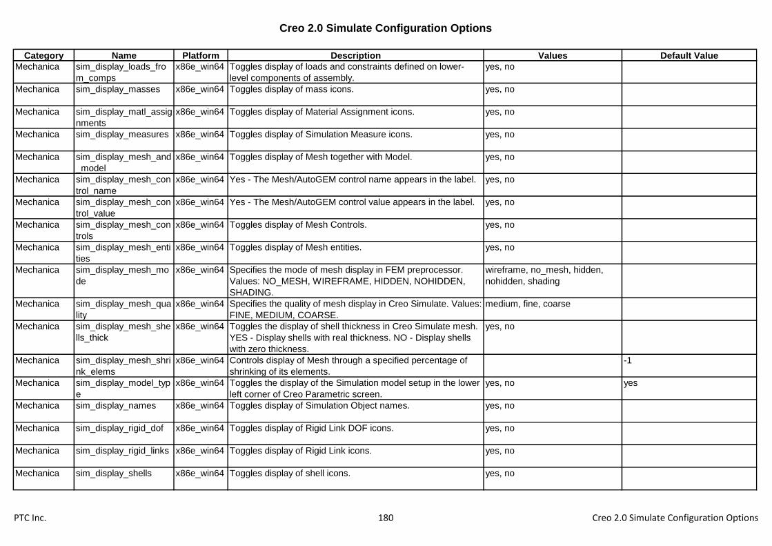
Creo 2.0 Simulate Configuration Options
Category Name Platform Description Values Default Value
Mechanica sim_display_loads_fro
m_comps
x86e_win64 Toggles display of loads and constraints defined on lower-
level components of assembly.
yes, no
Mechanica sim_display_masses x86e_win64 Toggles display of mass icons. yes, no
Mechanica sim_display_matl_assig
nments
x86e_win64 Toggles display of Material Assignment icons. yes, no
Mechanica sim_display_measures x86e_win64 Toggles display of Simulation Measure icons. yes, no
Mechanica sim_display_mesh_and
_model
x86e_win64 Toggles display of Mesh together with Model. yes, no
Mechanica sim_display_mesh_con
trol_name
x86e_win64 Yes - The Mesh/AutoGEM control name appears in the label. yes, no
Mechanica sim_display_mesh_con
trol_value
x86e_win64 Yes - The Mesh/AutoGEM control value appears in the label. yes, no
Mechanica sim_display_mesh_con
trols
x86e_win64 Toggles display of Mesh Controls. yes, no
Mechanica sim_display_mesh_enti
ties
x86e_win64 Toggles display of Mesh entities. yes, no
Mechanica sim_display_mesh_mo
de
x86e_win64 Specifies the mode of mesh display in FEM preprocessor.
Values: NO_MESH, WIREFRAME, HIDDEN, NOHIDDEN,
SHADING.
wireframe, no_mesh, hidden,
nohidden, shading
Mechanica sim_display_mesh_qua
lity
x86e_win64 Specifies the quality of mesh display in Creo Simulate. Values:
FINE, MEDIUM, COARSE.
medium, fine, coarse
Mechanica sim_display_mesh_she
lls_thick
x86e_win64 Toggles the display of shell thickness in Creo Simulate mesh.
YES - Display shells with real thickness. NO - Display shells
with zero thickness.
yes, no
Mechanica sim_display_mesh_shri
nk_elems
x86e_win64 Controls display of Mesh through a specified percentage of
shrinking of its elements.
-1
Mechanica sim_display_model_typ
e
x86e_win64 Toggles the display of the Simulation model setup in the lower
left corner of Creo Parametric screen.
yes, no yes
Mechanica sim_display_names x86e_win64 Toggles display of Simulation Object names. yes, no
Mechanica sim_display_rigid_dof x86e_win64 Toggles display of Rigid Link DOF icons. yes, no
Mechanica sim_display_rigid_links x86e_win64 Toggles display of Rigid Link icons. yes, no
Mechanica sim_display_shells x86e_win64 Toggles display of shell icons. yes, no
PTC Inc. 180 Creo 2.0 Simulate Configuration Options

Creo 2.0 Simulate Configuration Options
Category Name Platform Description Values Default Value
Mechanica sim_display_springs x86e_win64 Toggles display of spring icons. yes, no
Mechanica sim_display_struct_con
straints
x86e_win64 Toggles display of structure constraint icons. yes, no
Mechanica sim_display_struct_loa
ds
x86e_win64 Toggles display of structure load icons. yes, no
Mechanica sim_display_therm_bcs x86e_win64 Toggles display of Thermal Boundary Condition icons. yes, no
Mechanica sim_display_therm_loa
ds
x86e_win64 Toggles display of thermal load icons. yes, no
Mechanica sim_display_weighted_
dof
x86e_win64 Toggles display of Weighted Link DOF icons. yes, no
Mechanica sim_display_weighted_l
inks
x86e_win64 Toggles display of Weighted Link icons. yes, no
Mechanica sim_display_welds x86e_win64 Toggles display of Weld icons. yes, no
Mechanica sim_expanded_diagno
stics
x86e_win64 Yes - Creo Simulate will perform an expanded set of
diagnostic checks during meshing a model or running an
analysis. These include checks for interferences in an
assembly and for singular geometry. No - Creo Simulate will
not perform expanded checks.
yes, no no
Mechanica sim_extend_surf_max_
angle
x86e_win64 Controls the maximum angle between a surface to be
extended during shell compression and its adjacent surfaces.
If the angle is higher than specified, the adjacent surfaces is
extended. The default is 30 degrees. The range is from 0 to
90 degrees.
30
Mechanica sim_fatigue_biaxiality_c
orrect
x86e_win64 Controls the use of biaxiality correction. The default value is
YES.
yes, no yes
Mechanica sim_fatigue_biaxiality_
method
x86e_win64 Controls which method is used to model biaxiality: Klann-
Tipton-Cordes, Hoffman-Seeger, or the most conservative
(worst) of the two methods. The default value is WORST.
worst, ktc, hs worst
Mechanica sim_fatigue_confidence
_level
x86e_win64 Specifies the percentage confidence in the predicted life result
value. The default value is 90, and range is from 0.1 to 99.9
90
Mechanica sim_fatigue_external_
matdata
x86e_win64 Controls the use of external material data. The default value is
NO.
yes, no no
PTC Inc. 181 Creo 2.0 Simulate Configuration Options
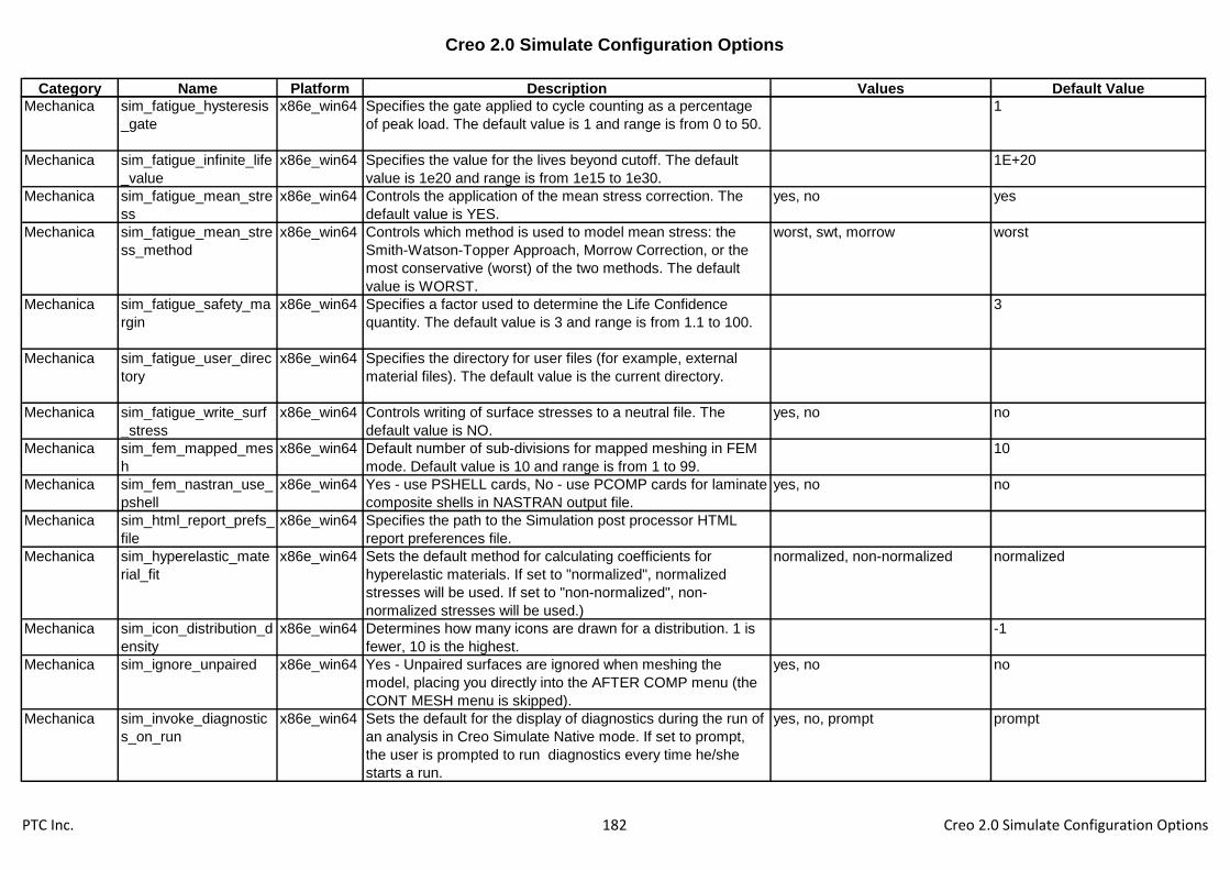
Creo 2.0 Simulate Configuration Options
Category Name Platform Description Values Default Value
Mechanica sim_fatigue_hysteresis
_gate
x86e_win64 Specifies the gate applied to cycle counting as a percentage
of peak load. The default value is 1 and range is from 0 to 50.
1
Mechanica sim_fatigue_infinite_life
_value
x86e_win64 Specifies the value for the lives beyond cutoff. The default
value is 1e20 and range is from 1e15 to 1e30.
1E+20
Mechanica sim_fatigue_mean_stre
ss
x86e_win64 Controls the application of the mean stress correction. The
default value is YES.
yes, no yes
Mechanica sim_fatigue_mean_stre
ss_method
x86e_win64 Controls which method is used to model mean stress: the
Smith-Watson-Topper Approach, Morrow Correction, or the
most conservative (worst) of the two methods. The default
value is WORST.
worst, swt, morrow worst
Mechanica sim_fatigue_safety_ma
rgin
x86e_win64 Specifies a factor used to determine the Life Confidence
quantity. The default value is 3 and range is from 1.1 to 100.
3
Mechanica sim_fatigue_user_direc
tory
x86e_win64 Specifies the directory for user files (for example, external
material files). The default value is the current directory.
Mechanica sim_fatigue_write_surf
_stress
x86e_win64 Controls writing of surface stresses to a neutral file. The
default value is NO.
yes, no no
Mechanica sim_fem_mapped_mes
h
x86e_win64 Default number of sub-divisions for mapped meshing in FEM
mode. Default value is 10 and range is from 1 to 99.
10
Mechanica sim_fem_nastran_use_
pshell
x86e_win64 Yes - use PSHELL cards, No - use PCOMP cards for laminate
composite shells in NASTRAN output file.
yes, no no
Mechanica sim_html_report_prefs_
file
x86e_win64 Specifies the path to the Simulation post processor HTML
report preferences file.
Mechanica sim_hyperelastic_mate
rial_fit
x86e_win64 Sets the default method for calculating coefficients for
hyperelastic materials. If set to "normalized", normalized
stresses will be used. If set to "non-normalized", non-
normalized stresses will be used.)
normalized, non-normalized normalized
Mechanica sim_icon_distribution_d
ensity
x86e_win64 Determines how many icons are drawn for a distribution. 1 is
fewer, 10 is the highest.
-1
Mechanica sim_ignore_unpaired x86e_win64 Yes - Unpaired surfaces are ignored when meshing the
model, placing you directly into the AFTER COMP menu (the
CONT MESH menu is skipped).
yes, no no
Mechanica sim_invoke_diagnostic
s_on_run
x86e_win64 Sets the default for the display of diagnostics during the run of
an analysis in Creo Simulate Native mode. If set to prompt,
the user is prompted to run diagnostics every time he/she
starts a run.
yes, no, prompt prompt
PTC Inc. 182 Creo 2.0 Simulate Configuration Options
Creo 2.0 Simulate Configuration Options
Category Name Platform Description Values Default Value
Mechanica sim_load_mech_mesh x86e_win64 No - The user is prompted to load the existing Creo Simulate
mesh file from the current working directory. Yes - The mesh
file, if exists, is loaded automatically and the mesh is
displayed.
yes, no no
Mechanica sim_loadpreview x86e_win64 Sets the type of load preview: vectors, fringe or mesh. vectors, fringe, mesh fringe
Mechanica sim_massnorm_modes x86e_win64 Mass normalize modes. If set to no, the modes are
normalized to a maximum displacement of 1. The default is
no.
yes, no no
Mechanica sim_mat_poissons_not
ation
x86e_win64 Specifies the convention used for defining Poisson's ratio for
anisotropic materials as being either Tsai (Column-
normalized) or Jones (Row-normalized). This option affects
only the labels for Poisson's ratio on the Material data form.
tsai, jones tsai
Mechanica sim_max_contact_itera
tions
x86e_win64 Specify the maximum number of iterations for contact
analysis. The default is 200.
200
Mechanica sim_max_memory_usa
ge
x86e_win64 Specifies the maximum amount of memory in megabytes to
be allocated during FEM meshing. If this option is not set, or
set to zero, the mesher can use all available memory.
Mechanica sim_modal_stress_sup
erposition
x86e_win64 If set to yes, use the modal stress superposition method to
compute the stress results. If set to no, use the
superconvergent stress recovery method.
yes, no yes
Mechanica sim_native_mapped_m
esh
x86e_win64 Default number of sub-divisions for mapped meshing in Native
mode. Default value is 3 and range is from 1 to 99.
3
Mechanica sim_output_ids_for_lay
ers
x86e_win64 Outputs FEM mesh element IDs on each layer into XML file. yes, no no
Mechanica sim_perturbation_solve
rs
x86e_win64 Use perturbation solvers in the calculation of local sensitivity.
The default is yes.
yes, no yes
Mechanica sim_pp_background_c
olor
x86e_win64 Specifies the background color of the work area for the results
display. The default value is PROE.
proe, blue, black, white proe
Mechanica sim_pp_display_beam_
thickness
x86e_win64 Sets the thickness for beams and 2D-shells display in Post
Processor. Numerical values specify the thickness in pixels.
1, 3, 2, 4, 5, actual 5
Mechanica sim_pp_display_spin_c
enter
x86e_win64 Sets the default for the behavior of mouse spinning the
model in results.
yes, no yes
PTC Inc. 183 Creo 2.0 Simulate Configuration Options

Creo 2.0 Simulate Configuration Options
Category Name Platform Description Values Default Value
Mechanica sim_pp_legacy_selecti
on
x86e_win64 Enables legacy selection of geometrical entities from Creo
Simulate results postprocessor on Creo Simulate geometry.
yes, no no
Mechanica sim_pp_legend_continu
ous
x86e_win64 Determines if the legend will be continuous tone (YES) or
discrete colors (NO).
yes, no no
Mechanica sim_pp_legend_levels x86e_win64 The default number of legend levels (from 1 to 16; the default
is 9).
9
Mechanica sim_pp_legend_show x86e_win64 If set to NO, the legend is not displayed in newly created
results windows by default.
yes, no yes
Mechanica sim_pp_legend_show_
min_max
x86e_win64 If set to NO, the gray minimum and maximum values are not
displayed by default in the legend.
yes, no yes
Mechanica sim_pp_legend_spectr
um
x86e_win64 This string sets the default color legend used in the definition
of a results window. This file will be looked up in the
sim_pp_template_dir location, or, if this is not specified, in the
current working directory.
Mechanica sim_pp_path_absolute x86e_win64 Choose Absolute (Yes) or Relative (No) path to "rwd" file. yes, no no
Mechanica sim_pp_query_location x86e_win64 Sets the default value for the display of the WCS location in
dynamic query in results.
yes, no no
Mechanica sim_pp_show_cap_cut
_outline
x86e_win64 Enables to hide the model outline in capping/cutting surface
display.
yes, no yes
Mechanica sim_pp_template_dir x86e_win64 Sets the default directory for results template files.
Mechanica sim_pp_vector_plot_arr
ow_2d
x86e_win64 To draw 2D arrows instead of 3D arrows while post-
processing vector results. It is useful when system memory is
not sufficient to display3D vector arrows.
yes, no no
Mechanica sim_pp_vrml_export_fo
rmat
x86e_win64 Flags to denote VRML1.0 or VRML2.0 (default) output. vrml2.0, vrml1.0 vrml2.0
Mechanica sim_pp_vrml_feature_e
dges
x86e_win64 Flag to enable the inclusion of feature edges in the VRML file.
The default value is NO.
yes, no no
Mechanica sim_reentrant_geom_a
ngle
x86e_win64 Sets the default value for reentrant geometry detection in both
Isolation for Exclusion AutoGEM Control and expanded
diagnostics checks. The valid range is from 0 to 180 degrees.
The default is 120 degrees.
120
Mechanica sim_remove_unoppose
d
x86e_win64 Yes - The system ignores unopposed surfaces when meshing
the model; the system also deselects the UseUnopposed
option. No - the system uses the unopposed surfaces in the
shell model.
yes, no no
PTC Inc. 184 Creo 2.0 Simulate Configuration Options

Creo 2.0 Simulate Configuration Options
Category Name Platform Description Values Default Value
Mechanica sim_results_on_first_p
ass
x86e_win64 Forces results post-processing after the first pass of an SPA
analysis.
yes, no no
Mechanica sim_run_out_dir x86e_win64 Specifies the directory for Creo Simulate run output storage.
By default, the current directory is used.
Mechanica sim_run_tmp_dir x86e_win64 Specifies the directory for Creo Simulate run temporary
storage. By default, the current directory is used.
Mechanica sim_smooth_aspect_ra
tio
x86e_win64 Sets the element aspect ratio criterion for the mesh smoothing
process.
7
Mechanica sim_smooth_edge_ang
le
x86e_win64 Sets the element edge angle criterion (Quad elements only),
measured in degrees, for the mesh smoothing process.
30
Mechanica sim_smooth_skew x86e_win64 Sets the element skew angle criterion (Quad elements only),
measured in degrees, for the mesh smoothing process.
45
Mechanica sim_smooth_taper x86e_win64 Sets the element taper criterion (Quad elements only) for the
mesh smoothing process.
0.5
Mechanica sim_smooth_warp_ang
le
x86e_win64 Sets the element warp angle criterion (Quad elements only),
measured in degrees, for the mesh smoothing process.
10
Mechanica sim_solver_memory_all
ocation
x86e_win64 Specifies the amount of memory in megabytes reserved for
solving equations and for storing element data created by the
iterative solver. The default value is 128.
512
Mechanica sim_spotweld_split_me
sh
x86e_win64 If set to YES (default), the elements that touch the end of the
spot weld are created in a circle the same diameter as the
weld (AutoGEM only).
yes, no yes
Mechanica sim_struct_interface_d
efault
x86e_win64 Sets the default for the interfaces created between the
geometry in a structural model for meshing and running
analysis.
free, bonded, contact
Mechanica sim_sturm_sequence x86e_win64 Run the Sturm sequence test for a modal analysis. By default,
the solver automatically decides when to perform the Sturm
sequence test.
never, default, always default
Mechanica sim_supercon_recover
y
x86e_win64 Sets on or off the superconvergent stress recovery algorithm. yes, no yes
Mechanica sim_therm_interface_d
efault
x86e_win64 Sets the default for the interfaces created between the
geometry in a thermal model for meshing and running
analysis.
bonded, resistance, adiabatic
Mechanica sim_use_layers x86e_win64 Allows layers to become groups for Creo Simulate
Independent mode.
yes, no no
PTC Inc. 185 Creo 2.0 Simulate Configuration Options

Creo 2.0 Simulate Configuration Options
Category Name Platform Description Values Default Value
Mechanica sim_wf5_fastener_fix_s
eparation
x86e_win64 Sets the value of Fix Separation for fasteners created in
Wildfire 5.0 or earlier with Fix Separation set to Auto.
yes, no, default default
Mechanica simulation_fem_mode x86e_win64 Yes - Activates FEM mode of Creo Simulate. No (default) -
Activates Native mode of Creo Simulate.
yes, no no
Mechanica simulation_mode x86e_win64 Sets Creo Simulate mode - Structure (default) or Thermal.
This option is used only if the information about Creo Simulate
mode is not yet stored with the model.
structure, thermal structure
Mechanica simulation_process_aut
o_advance
x86e_win64 If set to yes the Process Guide will advance to the next set
automatically upon completion of the current step.
yes, no no
Mechanica simulation_process_pr
ompt
x86e_win64 If set to yes, the Process Guide will be launched automatically
upon entry into Creo Simulate, if template files are present.
yes, no no
Mechanica simulation_process_te
mplate_dir
x86e_win64 Specifies the default location of the Process Guide template
files.
Mechanica std_nastran_template x86e_win64 Sets the file path of a NASTRAN deck template. Use full path
to avoid problems.
Mechanism mdo_cl_executable x86e_win64 Path for Custom Load executable.
Mechanism mdo_integration_metho
d
x86e_win64 Select integration method for dynamic analyses. explicit, implicit, auto auto
Mechanism mdo_spring_wire_radiu
s
x86e_win64 Spring wire radius for dynamics spring icons. 0.15
Mechanism mdx_belt_icon_width x86e_win64 Width of belt transmission icons. 5
Mechanism motion_envlp_alert x86e_win64 Displays the Motion Envelope alert the first time the quality
level is increased.
yes, no yes
Mechanism move_mechanism_in_
nongeom_reps
x86e_win64 Allow mechanism operations in non geometrical
representations.
yes, no, exclude_to_move yes
Miscellaneou
s
allow_ply_cross_sectio
n
x86e_win64 Yes - Enables Pro/COMPOSITE to create a cross-section of
composite plys.
yes, no yes
Miscellaneou
s
conf_mouse_anim x86e_win64 Display the presenter's mouse motions when observing a
shared Creo Parametric session.
yes, no no
Miscellaneou
s
mapkeys_execution x86e_win64 Mapkeys execution behavior. No Feedback - The mapkey is
executed with no feedback, Execute with Feedback - A
warning message is given upon failure during execution, Stop
at failure - The execution stops at failure and a feedback
message is provided.
no_feedback,
execute_with_feedback,
stop_at_failure
no_feedback
PTC Inc. 186 Creo 2.0 Simulate Configuration Options

Creo 2.0 Simulate Configuration Options
Category Name Platform Description Values Default Value
Miscellaneou
s
relation_text_trail_outp
ut
x86e_win64 No - Disable trail output from Text layout in Relation
Parameter UI if it hasn't been changed.
yes, no yes
Miscellaneou
s
relation_tool_mapkey_
behavior
x86e_win64 Will control how mapkeys will be executed in relation tool /
dialog. Incremental will add/remove text incrementally to the
current set. Full_output will record the original set state and
replace the current one with it. Note: this config is dependent
on relation_text_trail_output.
increment, full_output increment
Miscellaneou
s
show_cav_fit_loc_sys x86e_win64 Allows the printing of the transformation matrix of a Pro/Verify
Fit into a file.
yes, no no
Model Display allow_solid_perspective
_hlr
x86e_win64 Yes - Allows a solid to be displayed with hidden lines while in
perspective.
yes, no yes
Model Display animate_component_pl
acement
x86e_win64 Animate the transition between component states in
placement.
yes, no yes
Model Display animate_explode_state
s
x86e_win64 Animate the transition between explode states and mold
opening steps.
yes, no yes
Model Display blended_transparency x86e_win64 Yes - Transparent colors will appear using alpha blending (if
supported) when the model is shaded.
yes, no, independent yes
Model Display capped_clip x86e_win64 Yes - Displays the model as a solid when shaded and clipped.
No - Displays the model as surfaces when shaded and
clipped.
yes, no yes
Model Display clip_always x86e_win64 Yes - Display clipping after Visibilities dialog box is closed. yes, no yes
Model Display datum_point_symbol x86e_win64 Specifies the shape of datum point symbols displayed in Part
or Assembly mode.
dot cross
Model Display default_ramp_size x86e_win64 Specifies a number of shades of gray to show shading of non-
colored objects.
Model Display disp_comp_name_in_s
ymb_rep
x86e_win64 Displays the names of components in symbolic
representations.
yes, no yes
Model Display display x86e_win64 Wireframe - All solid edges in white. Hiddenvis - Hidden lines
in grey. Hiddeninvis - Hidden lines removed. Shade - Display
shaded surfaces. Settings are reflected in printing and some
export modes.
wireframe, hiddenvis,
hiddeninvis, shade,
shadewithreflect,
shadewithedges
shadewithedges
Model Display display_axes x86e_win64 Displays or hides datum axes. yes, no yes
Model Display display_axis_tags x86e_win64 Displays or hides datum axis name tags. yes, no no
PTC Inc. 187 Creo 2.0 Simulate Configuration Options

Creo 2.0 Simulate Configuration Options
Category Name Platform Description Values Default Value
Model Display display_coord_sys x86e_win64 Yes - Coordinate systems will be displayed. No - Coordinate
systems will not be displayed.
yes, no yes
Model Display display_coord_sys_tag
s
x86e_win64 Yes - Coordinate system name tags will be displayed. No -
Coordinate system name tags will not be displayed.
yes, no yes
Model Display display_florin x86e_win64 Yes: display of the florin (international currency symbol) where
possible. No: use the euro symbol exclusively.
yes, no no
Model Display display_plane_tags x86e_win64 Yes - Datum plane name tags will be displayed. No - Datum
plane name tags will not be displayed.
yes, no no
Model Display display_planes x86e_win64 Yes - Datum planes will be displayed. No - Datum planes will
not be displayed.
yes, no yes
Model Display display_point_tags x86e_win64 Yes - Datum point tags will be displayed. No - Datum point
tags will not be displayed.
yes, no no
Model Display display_points x86e_win64 Yes - Datum points and their names will be displayed. No -
Datum points and their names will not be displayed.
yes, no yes
Model Display display_silhouette_edg
es
x86e_win64 Sets the display of silhouette edges for wireframe display only. yes, no yes
Model Display display_z_extension_lin
es
x86e_win64 Controls the display of dimension z-extension lines. Yes - z-
extension lines will be displayed; No - z-extension lines will not
be displayed.
yes, no yes
Model Display edge_display_quality x86e_win64 Controls display quality of an edge for wireframe and hidden-
line removal. Normal - Normal quality of edge display. High -
Increases tessellation by 2. Very_high - Increases tessellation
by 3. Low - Decreases tessellation from normal, speeds up
display.
high, low, normal, very_high normal
Model Display enable_hlr_hashing x86e_win64 Enables hlr hashing yes, no no
Model Display enable_transparent_tex
t_bg
x86e_win64 Yes - Clear background before displaying text. No - Do not
clear text background.
yes, no yes
Model Display explode_animation_ma
x_time
x86e_win64 Sets the maximum amount of time for an animation between
explode states.
1
Model Display fast_highlight x86e_win64 Yes - Use simplified highlighting which redisplays more quickly
at the expense of certain details. This option may increase
memory usage slightly.
yes, no yes
Model Display fasthlr x86e_win64 Specifies whether fast hidden line removal is on/off by default. yes, no no
Model Display frames_per_sec x86e_win64 Determines whether view is animated. yes, no no
PTC Inc. 188 Creo 2.0 Simulate Configuration Options

Creo 2.0 Simulate Configuration Options
Category Name Platform Description Values Default Value
Model Display frames_per_sec_value x86e_win64 Used to set the smoothness of view animation changes.
Higher numbers provide more frames/sec, and giving you a
smoother animation. Lower numbers cause the view to
change more quickly.
3
Model Display lods_enabled x86e_win64 Determines whether or not the system uses Level of Detail in
shaded models during dynamic orientation (panning, zooming
and spinning).
yes, no no
Model Display lods_value x86e_win64 When lods_enabled is Yes, this value specifies the default
value used to display LODs. The value is a percentage of the
edge size vs the total size of the model.
50
Model Display max_animation_time x86e_win64 When the orientation, or zoom state, of the Creo Parametric
window changes, an animation sequence of a predefined
duration takes place. This option controls the maximum time
the system spends animating.
1
Model Display max_image_dimension x86e_win64 Set the upper bound dimension on images loaded into Creo
Parametric. Images larger than this limit will be rescaled to
this upper bound during loading.
4096, 1024, 2048, 8192, 16384 4096
Model Display mesh_spline_surf x86e_win64 Turns the blue mesh surface lines on or off. yes, no no
Model Display min_animation_steps x86e_win64 When the orientation, or zoom state, of the Creo Parametric
window changes, an animation sequence of predefined
duration takes place. This option controls the minimum
number of frames used in the animation sequence.
6
Model Display model_detail_options_fi
le
x86e_win64 Sets the path to the file which contains the default model detail
option values for new models.
<creo_loadpoint>\text\3d_inch.d
tl
Model Display orientation x86e_win64 Establishes the initial standard view orientation. User_default -
System uses X-axis and Y-axis values defined by options
x_axis and y_axis.
isometric, trimetric, user_default trimetric
Model Display real_time_rendering_di
splay
x86e_win64 Disable realtime rendering. disable, transparent_floor,
room_display
disable
Model Display save_triangles_flag x86e_win64 Spinning shaded images with software graphics only. Note:
This option has no effect if your system uses hardware
graphics.
yes, no no
Model Display shade_moving_comp x86e_win64 Yes - Shades assembly components while they are being
moved. No - Displays components in wireframe while they are
being moved.
yes, no yes
PTC Inc. 189 Creo 2.0 Simulate Configuration Options

Creo 2.0 Simulate Configuration Options
Category Name Platform Description Values Default Value
Model Display shade_quality x86e_win64 Model shade quality is used to decide how much to subdivide
surfaces for shading purposes. Higher shade quality is slower
but produces better pictures.
12, 13, 14, 1, 3, 23, 24, 25, 26, 2,
4, 5, 15, 6, 7, 8, 9, 10, 11, 16, 17,
18, 19, 20, 21, 22, 27, 28, 29, 30,
31, 32, 33, 34, 35, 36, 37, 38, 39,
40, 41, 42, 43, 44, 45, 46, 47, 48,
49, 50
3
Model Display shade_surface_feat x86e_win64 Controls the shading of surface features. yes, no yes
Model Display shade_windows x86e_win64 Enables shading of objects in all windows. This option does
not also enable color shading.
all_windows, one_window all_windows
Model Display shade_with x86e_win64 Controls the display of datum curves on shaded objects. no, curves curves
Model Display show_axes_for_extr_ar
cs
x86e_win64 Determines if axes are created for newly extruded arcs. yes, no no
Model Display skip_small_surfaces x86e_win64 Gives the user the option not to display small shaded
surfaces. Disabling this option will improve display quality at
the expense of speed. It is most useful for creating screen
snap shots.
yes, no yes
Model Display smooth_lines x86e_win64 Choose whether to smooth lines by default or not. yes, no no
Model Display spherical_map_size x86e_win64 Size of Spherical map texture image used for environment
mapping. Bigger size will have better image quality but will be
slow to regenerate.
256x256, 512x512, 1024x1024 256x256
Model Display spin_rate_zoom_sensiti
ve
x86e_win64 Allows slower spinning when zoomed in on a model. yes, no no
Model Display spin_with_notes x86e_win64 Yes - 3D feature and model notes are displayed during
dynamic spinning of a model.
yes, no yes
Model Display spin_with_part_entities x86e_win64 Yes - Datum features will be displayed during dynamic
spinning of a model.
yes, no no
Model Display spin_with_silhouettes x86e_win64 Yes - Silhouette lines will be displayed during dynamic
spinning of a model.
yes, no no
Model Display tan_angle_for_disp x86e_win64 For display purposes only. Sets the angle between two quilt
surfaces below which the edge will be displayed as tangent.
Enter an angle between 1.5 and 15 degrees.
0.02618
Model Display tangent_edge_display x86e_win64 Determines how edges between tangent surfaces are
displayed.
no, solid, centerline, phantom,
dimmed
solid
Model Display texture x86e_win64 Yes - Applied textures will be displayed when the model is
shaded.
yes, no yes
PTC Inc. 190 Creo 2.0 Simulate Configuration Options

Creo 2.0 Simulate Configuration Options
Category Name Platform Description Values Default Value
Model Display texture_search_path x86e_win64 Appends a directory to the search path for textures.
Model Display transparency x86e_win64 Yes - Transparent colors will appear as such when the model
is shaded.
yes, no yes
Model Display use_pre_wildfire_text_f
ont
x86e_win64 Yes - Use the old stroke-based PTC font as the default font.
No - Use a True Type font as the default font.
yes, no no
Model Display x_angle x86e_win64 Sets the default view orientation for models (appears in the
Orientation dialog box). The default orientation is the last
option, x_angle, y_angle, or orientation, in the configuration
file.
0
Model Display y_angle x86e_win64 Sets the default view orientation for models (appears in the
Orientation dialog box). The default orientation is the last
option, x_angle, y_angle, or orientation, in the configuration
file.
0
Photorender default_scene_filenam
e
x86e_win64 Complete path to the scene file to be used as default scene
file.
<creo_loadpoint>\graphic-
library\scenes\/creo_default_sce
ne.scn
Photorender photorender_capability
_warnings
x86e_win64 Allows the user to disable warnings about PhotoLux only
capabilities.
yes, no yes
Photorender photorender_default_h
eight
x86e_win64 Sets the default height (in pixels) for the custom size rendered
output
450
Photorender photorender_default_wi
dth
x86e_win64 Sets the default width (in pixels) for the custom size rendered
output
600
Photorender photorender_memory_
usage
x86e_win64 Sets the memory limit that Pro/PHOTORENDER allows for
model processing. Do not use commas in the memory value,
as Creo Parametric interprets these as decimals. The
minimum allowed value is 64 and maximum value is 5120.
256
Photorender photorender_preview_s
cale
x86e_win64 Allows user defined size ratio at which Pro/PHOTORENDER
will render, using the default Render To: Full Window Preview
setting. Increasing the value creates higher quality rendering
with slower performance. Reducing the value produces
reverse results.
0.5
Photorender pro_texture_library x86e_win64 Allows the user to specify a different graphics library.
PTC Inc. 191 Creo 2.0 Simulate Configuration Options

Creo 2.0 Simulate Configuration Options
Category Name Platform Description Values Default Value
Photorender room_rotation_lock x86e_win64 Default room rotation setting at session start. studio - Lock
room rotation to studio. model - Lock room rotation to model.
studio, model studio
Photorender save_scene_with_file x86e_win64 Yes - Automatically update the model with current scene
information when saving the model; No - Scene information
embedded in model must be updated manually.
yes, no no
Photorender save_texture_with_mod
el
x86e_win64 Yes - Embed applied texture and tracesketch bitmap files into
the model file.
yes, no no
Photorender window_gamma x86e_win64 Gamma correction to apply to images created by renderer.
Default value is 1.0.
1
Piping aec_dwg_anno_attrpar
_spec_file
x86e_win64 Specifies the aec drawing annotation attribute/parameter
specification file name.
aec_dwg_anno_attrparam_spec
.ptd
Piping aec_object_type_file x86e_win64 Specifies the aec object type file name. aec_object_type.ptd
Piping display_thick_insulation x86e_win64 Yes - Display insulation in thick mode. No - Display insulation
in centerline mode. This option can be overridden by the Thick
insulation option in the Model Display dialog box.
yes, no yes
Piping display_thick_pipes x86e_win64 Yes - Display pipes in thick mode. No - Display pipes in
centerline mode. This option can be overridden by the Thick
pipes option in the Model Display dialog box.
yes, no no
Piping isogen_attribute_map_f
ile
x86e_win64 Specifies the mapping between isogen parameter and
attribute name.
<creo_loadpoint>\text\piping_da
ta\isodata\isogen_attribute_map
.ptd
Piping isogen_endtype_map_f
ile
x86e_win64 Specify name of file mapping Pro/Piping endtypes with
ISOGEN endtypes
<creo_loadpoint>\text\piping_da
ta\isodata\isogen_endtype_map
.ptd
Piping isogen_mandatory_attr
_file
x86e_win64 Specify file containing mandatory attribute filenames used by
ISOGEN.
isogen.fls
Piping isogen_nominal_size_
map_file
x86e_win64 Specify name of file mapping Pro/Piping Size with Nominal
Sizes in MM and Inches
<creo_loadpoint>\text\piping_da
ta\isodata\isogen_nominal_size
_map.ptd
Piping isogen_output_files_dir x86e_win64 Specify directory to save the PCFs created by ISOGEN
interface
Piping isogen_pcf_filename_f
ormat
x86e_win64 Specify format to create filenames of PCF files being created mnemonic,-,specification,-
,number
PTC Inc. 192 Creo 2.0 Simulate Configuration Options

Creo 2.0 Simulate Configuration Options
Category Name Platform Description Values Default Value
Piping isogen_symbol_map_fil
e
x86e_win64 Specify name of file for mapping Pro/Piping selection names
with ISOGEN symbol keys (SKEY)s
<creo_loadpoint>\text\piping_da
ta\isodata\isogen_symbol_map.
ptd
Piping pipe_bend_locations_c
sys_units
x86e_win64 Define which assembly units will be used for the piping bend
locations calculations. Yes - to use coordinate system
assembly units. No - to use pipeline assembly units.
yes, no no
Piping pipe_pre_22_bendinfo_
conv
x86e_win64 Convert bend report information generated prior to
Pro/ENGINEER 2000i-2 to current saved analysis format.
yes, no yes
Piping pipe_solid_centerline x86e_win64 Yes - Display Pro/PIPING centerlines. No - Do not display
Pro/PIPING centerlines.
yes, no yes
Piping pipe_solid_label_format x86e_win64 Specify the pipe solid label format that will be used to
automatically generate pipeline labels.
size,-,specification,-,mnemonic,-
,number,-,insulation
Piping pipe_update_pre_20_in
t_pts
x86e_win64 Yes - Pipelines created prior to Release 20.0 are updated with
intersection point entities. The entities are created in session
by Info>Regen Info or when you retrieve the model.
yes, no no
Piping pipeline_assembly_libr
ary_dir
x86e_win64 Sets the default pipeline assembly library directory. <creo_loadpoint>\text\piping_da
ta\pipelinelib\
Piping pipeline_assembly_na
me_format
x86e_win64 Sets the default pipeline assembly name format. mnemonic,-,number
Piping pipeline_label_format x86e_win64 Specify the pipeline label format that will be used to
automatically generate pipeline labels.
size,-,specification,-,mnemonic,-
,number,-,insulation
Piping pipeline_solid_start_par
t_name
x86e_win64 Sets the default pipeline solid start part name. pipeline_solid_start.prt
Piping pipeline_spool_label_fo
rmat
x86e_win64 Specify the pipeline spool label format that will be used to
generate the spool labels during pipeline spool generation.
mnemonic-number-
prefix[0]spoolnum[01]
suffix[]
Piping pipeline_start_assembl
y_name
x86e_win64 Sets the default pipeline start assembly name. pipeline_start.asm
Piping piping_appearance_ma
p_file
x86e_win64 Sets the default piping appearance map filename. <creo_loadpoint>\text\piping_da
ta\master_catalog\piping_appea
rance.map
Piping piping_bolt_nut_select_
file
x86e_win64 Piping bolts and nuts selection file. <creo_loadpoint>\text\piping_da
ta\master_catalog\piping_bolt_n
ut_select.ptd
PTC Inc. 193 Creo 2.0 Simulate Configuration Options

Creo 2.0 Simulate Configuration Options
Category Name Platform Description Values Default Value
Piping piping_design_method x86e_win64 Sets the current Piping design method for pipeline modeling. non_spec_driven, spec_driven,
user_driven
non_spec_driven
Piping piping_enable_designat
e_report
x86e_win64 Enable designatable reports for spec-driven piping. yes, no yes
Piping piping_end_compatibilit
y_file
x86e_win64 Sets the default piping end compatibility filename. <creo_loadpoint>\text\piping_da
ta\master_catalog\piping_end_c
ompatibility.ptd
Piping piping_extend_dim_sch
eme
x86e_win64 Specify a dimension scheme for piping extend segment. cartesian, cylindrical, spherical cartesian
Piping piping_extend_show_c
sys
x86e_win64 Control whether small preview CSYS is shown at end of pipe
when defining extend features in cartesian / spherical /
cylindrical schemes.
yes, no no
Piping piping_fitt_angle_tolera
nce
x86e_win64 Sets the default piping fitting angle tolerance value. 1.5
Piping piping_fitt_category_m
ap_file
x86e_win64 Sets the default piping fitting category map filename. <creo_loadpoint>\text\piping_da
ta\sample_project\piping_fitt_cat
egory_map.ptd
Piping piping_fitt_library_dir x86e_win64 Sets the default piping fitting library directory. <creo_loadpoint>\text\piping_da
ta\fittinglib\
Piping piping_fluid_parameter x86e_win64 Enables/disables the Parameters tab in Create Pipeline Dialog yes, no no
Piping piping_insulation_dir_fil
e
x86e_win64 Sets the default piping insulation directory filename. <creo_loadpoint>\text\piping_da
ta\sample_project\piping_insulat
ion_dir.ptd
Piping piping_joint_fitting_clea
rance
x86e_win64 Sets the piping joint minimum fitting clearance value. 1
Piping piping_joint_fitting_offs
et
x86e_win64 Sets the piping joint minimum fitting offset value. 1
Piping piping_manufacture_dir
_file
x86e_win64 Sets the default piping manufacture directory filename. <creo_loadpoint>\text\piping_da
ta\master_catalog\piping_manuf
acture_dir.ptd
Piping piping_material_file x86e_win64 Sets the default piping material filename. <creo_loadpoint>\text\piping_da
ta\master_catalog\piping_materi
al.ptd
Piping piping_material_source x86e_win64 Sets the source for material information. Note Material_dir
requires pro_material_dir to be set.
weight_length, material_dir weight_length
Piping piping_mcat_dir x86e_win64 Sets the default piping master catalog directory. <creo_loadpoint>\text\piping_da
ta\master_catalog\
PTC Inc. 194 Creo 2.0 Simulate Configuration Options
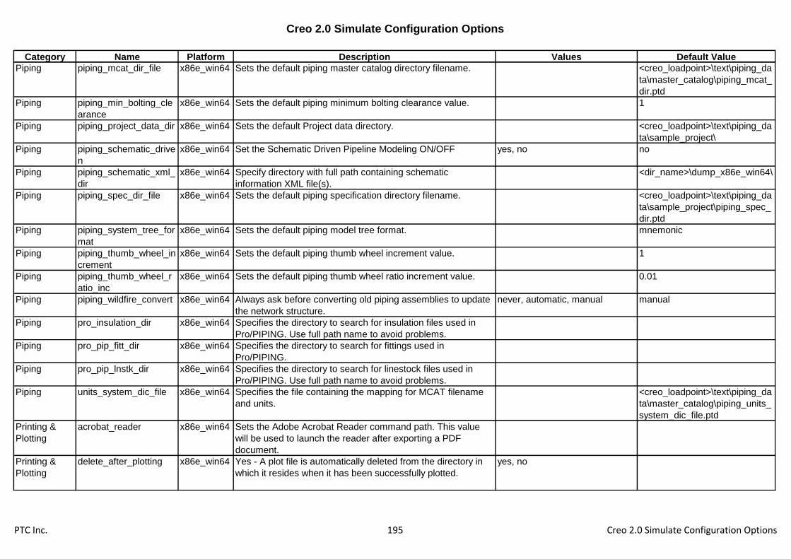
Creo 2.0 Simulate Configuration Options
Category Name Platform Description Values Default Value
Piping piping_mcat_dir_file x86e_win64 Sets the default piping master catalog directory filename. <creo_loadpoint>\text\piping_da
ta\master_catalog\piping_mcat_
dir.ptd
Piping piping_min_bolting_cle
arance
x86e_win64 Sets the default piping minimum bolting clearance value. 1
Piping piping_project_data_dir x86e_win64 Sets the default Project data directory. <creo_loadpoint>\text\piping_da
ta\sample_project\
Piping piping_schematic_drive
n
x86e_win64 Set the Schematic Driven Pipeline Modeling ON/OFF yes, no no
Piping piping_schematic_xml_
dir
x86e_win64 Specify directory with full path containing schematic
information XML file(s).
<dir_name>\dump_x86e_win64\
Piping piping_spec_dir_file x86e_win64 Sets the default piping specification directory filename. <creo_loadpoint>\text\piping_da
ta\sample_project\piping_spec_
dir.ptd
Piping piping_system_tree_for
mat
x86e_win64 Sets the default piping model tree format. mnemonic
Piping piping_thumb_wheel_in
crement
x86e_win64 Sets the default piping thumb wheel increment value. 1
Piping piping_thumb_wheel_r
atio_inc
x86e_win64 Sets the default piping thumb wheel ratio increment value. 0.01
Piping piping_wildfire_convert x86e_win64 Always ask before converting old piping assemblies to update
the network structure.
never, automatic, manual manual
Piping pro_insulation_dir x86e_win64 Specifies the directory to search for insulation files used in
Pro/PIPING. Use full path name to avoid problems.
Piping pro_pip_fitt_dir x86e_win64 Specifies the directory to search for fittings used in
Pro/PIPING.
Piping pro_pip_lnstk_dir x86e_win64 Specifies the directory to search for linestock files used in
Pro/PIPING. Use full path name to avoid problems.
Piping units_system_dic_file x86e_win64 Specifies the file containing the mapping for MCAT filename
and units.
<creo_loadpoint>\text\piping_da
ta\master_catalog\piping_units_
system_dic_file.ptd
Printing &
Plotting
acrobat_reader x86e_win64 Sets the Adobe Acrobat Reader command path. This value
will be used to launch the reader after exporting a PDF
document.
Printing &
Plotting
delete_after_plotting x86e_win64 Yes - A plot file is automatically deleted from the directory in
which it resides when it has been successfully plotted.
yes, no
PTC Inc. 195 Creo 2.0 Simulate Configuration Options

Creo 2.0 Simulate Configuration Options
Category Name Platform Description Values Default Value
Printing &
Plotting
din_std_line_priority x86e_win64 If set to YES line priority in plotting or export is determined
according to DIN standard
yes, no no
Printing &
Plotting
gerber_360_interpolatio
n
x86e_win64 Yes - Arcs and circles included in outputted Gerber plot files
will take this format.
yes, no no
Printing &
Plotting
pen_slew x86e_win64 Sets the pen speed for both x and y directions for plotters that
are compatible with this option. Consult your plotter's user
guide for more information.
-1.000000 0.000000
Printing &
Plotting
pen_slew_xy x86e_win64 Sets the pen speed for the x and y directions individually for
plotters that are compatible with this option. The first value is
the x value and the second, the y value. They should be
separated by a space.
-1.000000 0.000000
Printing &
Plotting
pen_table_file x86e_win64 Specifies a default pen mapping table which supersedes other
pen mapping information.
table.pnt
Printing &
Plotting
pen1_line_weight x86e_win64 Sets the weight of entities plotted with pens using an
electrostatic plotter. The weight is a range from 1 (thinnest) to
16 (thickest).
4
Printing &
Plotting
pen2_line_weight x86e_win64 Sets the weight of entities plotted with pens using an
electrostatic plotter. The weight is a range from 1 (thinnest) to
16 (thickest).
1
Printing &
Plotting
pen3_line_weight x86e_win64 Sets the weight of entities plotted with pens using an
electrostatic plotter. The weight is a range from 1 (thinnest) to
16 (thickest).
2
Printing &
Plotting
pen4_line_weight x86e_win64 Sets the weight of entities plotted with pens using an
electrostatic plotter. The weight is a range from 1 (thinnest) to
16 (thickest).
3
Printing &
Plotting
pen5_line_weight x86e_win64 Sets the weight of entities plotted with pens using an
electrostatic plotter. The weight is a range from 1 (thinnest) to
16 (thickest).
2
Printing &
Plotting
pen6_line_weight x86e_win64 Sets the weight of entities plotted with pens using an
electrostatic plotter. The weight is a range from 1 (thinnest) to
16 (thickest).
3
Printing &
Plotting
pen7_line_weight x86e_win64 Sets the weight of entities plotted with pens using an
electrostatic plotter. The weight is a range from 1 (thinnest) to
16 (thickest).
1
Printing &
Plotting
pen8_line_weight x86e_win64 Sets the weight of entities plotted with pens using an
electrostatic plotter. The weight is a range from 1 (thinnest) to
16 (thickest).
4
PTC Inc. 196 Creo 2.0 Simulate Configuration Options

Creo 2.0 Simulate Configuration Options
Category Name Platform Description Values Default Value
Printing &
Plotting
plot_carberry_extends x86e_win64 When plotting to a raster format (jpg, tiff, etc), set to YES to
ignore the view border and produce output sized to the
smallest rectangle that includes the drawing items.
yes, no no
Printing &
Plotting
plot_file_dir x86e_win64 Specifies the directory where plot files should be written. Use
the full pathname to avoid problems. For example
/home/users/plotfiles.
Printing &
Plotting
plot_linestyle_scale x86e_win64 Specifies the scaling factor for the DOTFONT line style in a
plot.
1
Printing &
Plotting
plot_names x86e_win64 Yes - Plot files are given descriptive extensions when created.
No - All plot files are simply given the extension .plt.
yes, no
Printing &
Plotting
plot_proceed_dialog x86e_win64 Yes - Enables the Plot Proceed dialog which provides a
choice for delaying the printing of plot files. This is useful for
large plots when using lp print commands. The lp command
may not access the plot file before it is removed resulting in no
output.
yes, no no
Printing &
Plotting
plot_to_scale_full_wind
ow
x86e_win64 Provides the ability to exclude empty window space when
plotting the model to scale.
yes, no
Printing &
Plotting
plotter x86e_win64 Establishes the default plotter for making plot files.
Printing &
Plotting
plotter_command x86e_win64 Sets the command that you use to start a plot on your system;
for Windows NT or Windows 95, windows_print_manager
option configures Creo Parametric to plot to a recognized
device in the Windows NT or Windows 95 print manager.
windows_print_manager
Printing &
Plotting
plotter_handshake x86e_win64 Specifies the type of plotter handshake initialization sequence
generated in the plotter files.
hardware, software
Printing &
Plotting
postscript_compression x86e_win64 Specifies whether or not to compress exported shaded
PostScript files. Yes - A shaded postscript file created with
File>Export will be compressed. This will increase processing
time.
yes, no no
Printing &
Plotting
pro_plot_config_dir x86e_win64 Sets the directory of your user-defined plotter configuration
file. Use the full pathname to avoid problems.
PTC Inc. 197 Creo 2.0 Simulate Configuration Options

Creo 2.0 Simulate Configuration Options
Category Name Platform Description Values Default Value
Printing &
Plotting
ps_output_with_pagesi
ze
x86e_win64 Specifies whether or not to include pagesize information when
generating postscript files from Creo Parametric. No - Creo
Parametric will omit Adobe level 2 pagesize information from
the header of the postscript file.
yes, no yes
Printing &
Plotting
raster_plot_dpi x86e_win64 Determines the resolution for plotter outputs variables are in
dots per inch.
100, 200, 300, 400 100
Printing &
Plotting
rotate_postscript_print x86e_win64 Specifies rotation for printing. Yes - Rotates a PostScript plot
90 degrees counterclockwise. Use when you are plotting a
landscape drawing on a portrait-type laser printer, or a portrait
drawing on a landscape-type laser printer.
yes, no
Printing &
Plotting
shaded_postscript_bac
kground
x86e_win64 Specifies how background colors are handled in Postscript
files of shaded objects.
yes, no no
Printing &
Plotting
ttf_handling_for_plot_fil
es
x86e_win64 Defines how annotations using True Type Fonts are written to
the plot file. Using True Type Fonts reduces the plot file size,
but font substitution may occur due to device settings.
Annotations that do not use True Type Fonts are unaffected
by this option.
stroke all fonts, use true type
fonts
use true type fonts
Printing &
Plotting
use_8_plotter_pens x86e_win64 Specifies whether to support up to 8 plotter pens. The initial
default is 4 pens.
yes, no no
Printing &
Plotting
use_software_linefonts x86e_win64 Yes - The exact line style used in Creo Parametric is plotted,
stroked out dot by dot, dash by dash, and space by space. No -
plots lines using the line font it supports which most closely
resembles the font used in Creo Parametric.
yes, no no
Printing &
Plotting
variable_plots_in_inche
s
x86e_win64 No - Variable plot sizes may be entered in millimeters. yes, no yes
Printing &
Plotting
versatec_cutter_installe
d
x86e_win64 Yes - Indicates that a cutter is installed on a Versatec plotter. yes, no
Sheetmetal close_corner_relief x86e_win64 Closes the gap between the bend surfaces of a corner that is
a result of intersecting walls in the form state.
yes, no no
Sheetmetal enable_flat_state x86e_win64 Enables the creation of a flat state instance of the model. The
instance can be fully flat or fully formed.
yes, no no
Sheetmetal flange_shape_sketches
_directory
x86e_win64 Sets path to directory that contains the Flange shapes.
Sheetmetal flat_shape_sketches_di
rectory
x86e_win64 Sets path to directory that contains the Flat shapes.
PTC Inc. 198 Creo 2.0 Simulate Configuration Options
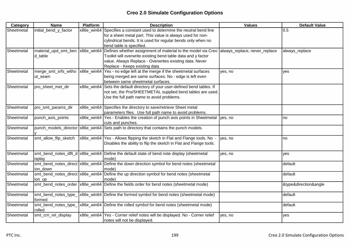
Creo 2.0 Simulate Configuration Options
Category Name Platform Description Values Default Value
Sheetmetal initial_bend_y_factor x86e_win64 Specifies a constant used to determine the neutral bend line
for a sheet metal part. This value is always used for non-
cylindrical bends. It is used for regular bends only when no
bend table is specified.
0.5
Sheetmetal material_upd_smt_ben
d_table
x86e_win64 Defines whether assignment of material to the model via Creo
Toolkit will overwrite existing bend table data and y factor
value. Always Replace - Overwrites existing data. Never
Replace - Keeps existing data
always_replace, never_replace always_replace
Sheetmetal merge_smt_srfs_witho
ut_seam
x86e_win64 Yes - no edge left at the merge if the sheetmetal surfaces
being merged are same surfaces. No - edge is left even
between same sheetmetal surfaces.
yes, no yes
Sheetmetal pro_sheet_met_dir x86e_win64 Sets the default directory of your user-defined bend tables. If
not set, the Pro/SHEETMETAL supplied bend tables are used.
Use the full path name to avoid problems.
Sheetmetal pro_smt_params_dir x86e_win64 Specifies the directory to save/retrieve Sheet metal
parameters files. Use full path name to avoid problems.
Sheetmetal punch_axis_points x86e_win64 Yes - Enables the creation of punch axis points in Sheetmetal
cuts and punches.
yes, no no
Sheetmetal punch_models_director
y
x86e_win64 Sets path to directory that contains the punch models.
Sheetmetal smt_allow_flip_sketch x86e_win64 Yes - Allows flipping the sketch in Flat and Flange tools. No -
Disables the ability to flip the sketch in Flat and Flange tools.
yes, no no
Sheetmetal smt_bend_notes_dflt_d
isplay
x86e_win64 Define the default state of bend note display (sheetmetal
mode)
yes, no yes
Sheetmetal smt_bend_notes_direct
ion_down
x86e_win64 Define the down direction symbol for bend notes (sheetmetal
mode)
default
Sheetmetal smt_bend_notes_direct
ion_up
x86e_win64 Define the up direction symbol for bend notes (sheetmetal
mode)
default
Sheetmetal smt_bend_notes_order x86e_win64 Define the fields order for bend notes (sheetmetal mode) &type&direction&angle
Sheetmetal smt_bend_notes_type_
formed
x86e_win64 Define the formed symbol for bend notes (sheetmetal mode) default
Sheetmetal smt_bend_notes_type_
rolled
x86e_win64 Define the rolled symbol for bend notes (sheetmetal mode) default
Sheetmetal smt_crn_rel_display x86e_win64 Yes - Corner relief notes will be displayed. No - Corner relief
notes will not be displayed.
yes, no yes
PTC Inc. 199 Creo 2.0 Simulate Configuration Options
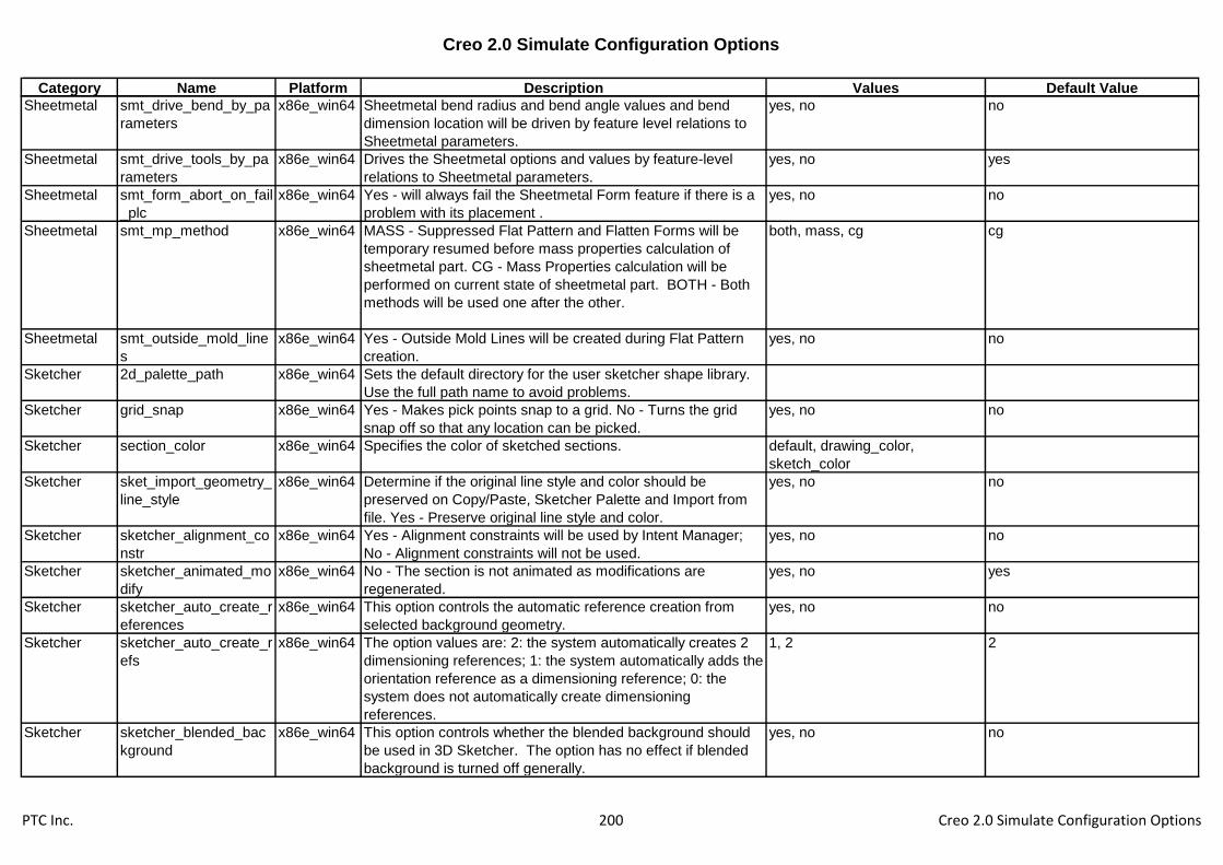
Creo 2.0 Simulate Configuration Options
Category Name Platform Description Values Default Value
Sheetmetal smt_drive_bend_by_pa
rameters
x86e_win64 Sheetmetal bend radius and bend angle values and bend
dimension location will be driven by feature level relations to
Sheetmetal parameters.
yes, no no
Sheetmetal smt_drive_tools_by_pa
rameters
x86e_win64 Drives the Sheetmetal options and values by feature-level
relations to Sheetmetal parameters.
yes, no yes
Sheetmetal smt_form_abort_on_fail
_plc
x86e_win64 Yes - will always fail the Sheetmetal Form feature if there is a
problem with its placement .
yes, no no
Sheetmetal smt_mp_method x86e_win64 MASS - Suppressed Flat Pattern and Flatten Forms will be
temporary resumed before mass properties calculation of
sheetmetal part. CG - Mass Properties calculation will be
performed on current state of sheetmetal part. BOTH - Both
methods will be used one after the other.
both, mass, cg cg
Sheetmetal smt_outside_mold_line
s
x86e_win64 Yes - Outside Mold Lines will be created during Flat Pattern
creation.
yes, no no
Sketcher 2d_palette_path x86e_win64 Sets the default directory for the user sketcher shape library.
Use the full path name to avoid problems.
Sketcher grid_snap x86e_win64 Yes - Makes pick points snap to a grid. No - Turns the grid
snap off so that any location can be picked.
yes, no no
Sketcher section_color x86e_win64 Specifies the color of sketched sections. default, drawing_color,
sketch_color
Sketcher sket_import_geometry_
line_style
x86e_win64 Determine if the original line style and color should be
preserved on Copy/Paste, Sketcher Palette and Import from
file. Yes - Preserve original line style and color.
yes, no no
Sketcher sketcher_alignment_co
nstr
x86e_win64 Yes - Alignment constraints will be used by Intent Manager;
No - Alignment constraints will not be used.
yes, no no
Sketcher sketcher_animated_mo
dify
x86e_win64 No - The section is not animated as modifications are
regenerated.
yes, no yes
Sketcher sketcher_auto_create_r
eferences
x86e_win64 This option controls the automatic reference creation from
selected background geometry.
yes, no no
Sketcher sketcher_auto_create_r
efs
x86e_win64 The option values are: 2: the system automatically creates 2
dimensioning references; 1: the system automatically adds the
orientation reference as a dimensioning reference; 0: the
system does not automatically create dimensioning
references.
1, 2 2
Sketcher sketcher_blended_bac
kground
x86e_win64 This option controls whether the blended background should
be used in 3D Sketcher. The option has no effect if blended
background is turned off generally.
yes, no no
PTC Inc. 200 Creo 2.0 Simulate Configuration Options

Creo 2.0 Simulate Configuration Options
Category Name Platform Description Values Default Value
Sketcher sketcher_collinear_con
str
x86e_win64 Yes - collinear constraints will be used by Intent Manager; No -
collinear constraints will not be used by Intent Manager.
yes, no yes
Sketcher sketcher_default_font_
kerning
x86e_win64 Automatically set kerning for text entities in Sketcher. Yes -
Kerning will be set for new text entities. No - Kerning will not
be set automatically.
yes, no no
Sketcher sketcher_diagonal_con
str
x86e_win64 Yes - Diagonal constraints will be used; No - Diagonal
constraints will not be used.
yes, no no
Sketcher sketcher_dim_of_revol
ve_axis
x86e_win64 If this option is set all dimensions created by Intent Manager to
Axis of Revolution will be diameter dimensions.
yes, no yes
Sketcher sketcher_dimension_a
utolock
x86e_win64 Automatically lock strong sketcher dimensions. yes, no no
Sketcher sketcher_disp_constrai
nts
x86e_win64 Shows the constraints when sketching in Sketcher Mode; for
example, H for horizontal, V for vertical, and so on.
yes, no yes
Sketcher sketcher_disp_dimensi
ons
x86e_win64 No - Suppresses the display of all dimensions while in
sketcher.
yes, no yes
Sketcher sketcher_disp_grid x86e_win64 Specify whether or not to display the sketcher grid. yes, no no
Sketcher sketcher_disp_vertices x86e_win64 No - Suppresses the display of yellow points on all vertices
while in sketcher.
yes, no yes
Sketcher sketcher_disp_weak_di
mensions
x86e_win64 Yes - weak dimensions will be displayed; No - weak
dimensions will not be displayed.
yes, no yes
Sketcher sketcher_equal_length
_constr
x86e_win64 Yes - equal length constraints will be used by Intent Manager;
No - equal length constraints will not be used by Intent
Manager.
yes, no yes
Sketcher sketcher_equal_radii_c
onstr
x86e_win64 Yes - equal radii constraints will be used by Intent Manager;
No - equal radii constraints will not be used by Intent Manager.
yes, no yes
Sketcher sketcher_grid_angle x86e_win64 Enter a grid angle value to override the default grid angle
value.
0
Sketcher sketcher_grid_line_qua
ntity
x86e_win64 Enter number of radial lines for radial grid. 12
Sketcher sketcher_grid_radius_s
pacing
x86e_win64 Enter a radial grid spacing value to override the default radial
grid spacing value.
1
Sketcher sketcher_grid_type x86e_win64 Set grid type to be Cartesian or Polar. cartesian, polar cartesian
PTC Inc. 201 Creo 2.0 Simulate Configuration Options

Creo 2.0 Simulate Configuration Options
Category Name Platform Description Values Default Value
Sketcher sketcher_highlight_ope
n_ends
x86e_win64 Yes - Highlights open ends of sketched entities in Sketcher.
No - Does not highlight open ends of sketched entities in
Sketcher.
yes, no yes
Sketcher sketcher_import_exact
_geom
x86e_win64 During import in sketcher use exact geometry. yes, no yes
Sketcher sketcher_known_dim_o
n_ref_ent
x86e_win64 YES - create known dimensions on known geometry, NO -
create reference dimensions on known geometry
yes, no yes
Sketcher sketcher_lineup_hor_c
onstr
x86e_win64 Yes - line up horizontal constraints will be used by Intent
Manager; No - line up horizontal constraints will not be used
by Intent Manager.
yes, no yes
Sketcher sketcher_lineup_ver_c
onstr
x86e_win64 Yes - line up vertical constraints will be used by Intent
Manager; No - line up vertical constraints will not be used by
Intent Manager.
yes, no yes
Sketcher sketcher_lock_modified
_dims
x86e_win64 Yes - modified dimensions will be locked; No - modified
dimensions will not be locked.
yes, no no
Sketcher sketcher_midpoint_con
str
x86e_win64 Yes - midpoint constraints will be used by Intent Manager; No -
midpoint constraints will not be used by Intent Manager.
yes, no yes
Sketcher sketcher_parallel_const
r
x86e_win64 Yes - parallel constraints will be used by Intent Manager; No -
parallel constraints will not be used by Intent Manager.
yes, no yes
Sketcher sketcher_perpendicular
_constr
x86e_win64 Yes - perpendicular constraints will be used by Intent
Manager; No - perpendicular constraints will not be used by
Intent Manager.
yes, no yes
Sketcher sketcher_point_on_enti
ty_constr
x86e_win64 Yes - point on entity constraints will be used by Intent
Manager; No - point on entity constraints will not be used by
Intent Manager.
yes, no yes
Sketcher sketcher_refit_after_di
m_modify
x86e_win64 Refits section after dimension modification in 2D section or
when creating the first feature.
yes, no yes
Sketcher sketcher_rel_accuracy x86e_win64 Enter a sketcher relative accuracy. -1
Sketcher sketcher_same_point_
constr
x86e_win64 Yes - same points constraints will be used by Intent Manager;
No - same points constraints will not be used by Intent
Manager.
yes, no yes
Sketcher sketcher_save_preview
_image
x86e_win64 This option controls whether section files should be saved with
embedded image information which can be used to preview
sections in File/Open dialog.
yes, no no
PTC Inc. 202 Creo 2.0 Simulate Configuration Options
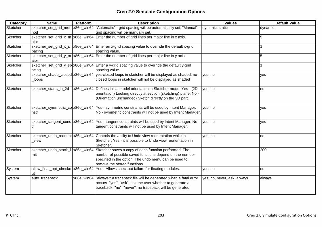
Creo 2.0 Simulate Configuration Options
Category Name Platform Description Values Default Value
Sketcher sketcher_set_grid_met
hod
x86e_win64 "Automatic" - grid spacing will be automatically set, "Manual" -
grid spacing will be manually set.
dynamic, static dynamic
Sketcher sketcher_set_grid_x_m
ajor
x86e_win64 Enter the number of grid lines per major line in x axis. 5
Sketcher sketcher_set_grid_x_s
pacing
x86e_win64 Enter an x-grid spacing value to override the default x-grid
spacing value.
1
Sketcher sketcher_set_grid_y_m
ajor
x86e_win64 Enter the number of grid lines per major line in y axis. 5
Sketcher sketcher_set_grid_y_sp
acing
x86e_win64 Enter a y-grid spacing value to override the default y-grid
spacing value.
1
Sketcher sketcher_shade_closed
_loops
x86e_win64 yes-closed loops in sketcher will be displayed as shaded, no-
closed loops in sketcher will not be displayed as shaded
yes, no yes
Sketcher sketcher_starts_in_2d x86e_win64 Defines initial model orientation in Sketcher mode. Yes - (2D
orientation) Looking directly at section (sketching) plane. No -
(Orientation unchanged) Sketch directly on the 3D part.
yes, no no
Sketcher sketcher_symmetric_co
nstr
x86e_win64 Yes - symmetric constraints will be used by Intent Manager;
No - symmetric constraints will not be used by Intent Manager.
yes, no yes
Sketcher sketcher_tangent_cons
tr
x86e_win64 Yes - tangent constraints will be used by Intent Manager; No -
tangent constraints will not be used by Intent Manager.
yes, no yes
Sketcher sketcher_undo_reorient
_view
x86e_win64 Controls the ability to Undo view reorientation while in
Sketcher. Yes - it is possible to Undo view reorientation in
Sketcher.
yes, no no
Sketcher sketcher_undo_stack_li
mit
x86e_win64 Sketcher saves a copy of each function performed. The
number of possible saved functions depend on the number
specified in the option. The undo menu can be used to
remove the stored functions.
200
System allow_float_opt_checko
ut
x86e_win64 Yes - Allows checkout failure for floating modules. yes, no no
System auto_traceback x86e_win64 "always": a traceback file will be generated when a fatal error
occurs. "yes", "ask": ask the user whether to generate a
traceback. "no", "never": no traceback will be generated.
yes, no, never, ask, always always
PTC Inc. 203 Creo 2.0 Simulate Configuration Options

Creo 2.0 Simulate Configuration Options
Category Name Platform Description Values Default Value
System cmdmgr_trail_output x86e_win64 Trail file and mapkey output will include system instructions
that are independent of user interface configuration when
available (typically menu bar and toolbar options).
yes, no yes
System cpus_to_use x86e_win64 Set up the number of threads including main thread 2
System enable_tree_indep x86e_win64 Setup whether tree customization will allow separating the tree
window from Creo Parametric window.
yes, no no
System export_report_format x86e_win64 Controls the format of the exported reports displayed in the
embedded browser. Rich Text - Exports the report in Rich
Text format, Comma Delimited - Exports the report in Comma
Delimited format.
comma_delimited, rich_text comma_delimited
System general_undo_stack_li
mit
x86e_win64 Setup the default number of entries in the top level
Undo/Redo (default = 50).
50
System graphics x86e_win64 Sets the optional graphics environment used by certain
platforms for running Creo Parametric. Refer to the Installation
Guide for a list of defaults and optional graphics.
opengl, x_windows, win32_gdi,
d3d
no_graphics
System overlays_enabled x86e_win64 Yes - Enables Creo Parametric screens and menus to be
placed on different overlay layers of the hardware graphics
card. This frees memory for Creo Parametric use.
yes, no no
System pick_aperture_radius x86e_win64 Specifies the size of the area about the mouse when making
selections. Units are 1/1000 of screen size.
7
System protable_in_backgroun
d
x86e_win64 Yes - Starts Pro/TABLE editor in the background. Reduces
time between pressing a menu button that uses Pro/TABLE
and entering the data.
yes, no yes
System saveunders_enabled x86e_win64 Yes - Enables Creo Parametric popup helptext and menus to
retain the portion of the window they obscure to be used to
restore the window image when they are dismissed.
yes, no yes
System set_trail_single_step x86e_win64 Yes - Enables a trail file to be single-stepped by entering
<CR>.
yes, no no
System tablet_device_name x86e_win64 Specifies the name of a digitizing tablet.
System trail_delay x86e_win64 Sets a delay in seconds between trail file steps.
PTC Inc. 204 Creo 2.0 Simulate Configuration Options

Creo 2.0 Simulate Configuration Options
Category Name Platform Description Values Default Value
System trail_dir x86e_win64 Instructs Creo Parametric to create its trail file in the specified
directory rather than in the startup directory.
System train_file_path x86e_win64 Specifies the default directory for training files. The path name
must start from the root of the directory, for example,
/home/users/library/training.
System use_software_opengl x86e_win64 Use MS-Windows software OpenGL. In some cases this may
avoid graphics card specific problems at the expense of
performance.
yes, no no
System web_browser_history_d
ays
x86e_win64 Enter number of days to store history records. 20
System web_browser_homepa
ge
x86e_win64 Enter location of Creo Parametric browser home page. <creo_loadpoint>\help\usascii\re
source_center_index.html
System web_browser_in_separ
ate_window
x86e_win64 Specifies whether Creo Parametrics web browser should be
launched as a separate window. When set to Yes the
browser will be displayed as a separate window. The default,
No, will result in the browser being embedded in the Creo
Parametric application window
yes, no no
System windows_browser_type x86e_win64 Select the type of embedded browser to use. ie_in_process,
ie_in_sep_process,
mozilla_based_browser
ie_in_process
User
Interface
ae_propagate_detail_d
ependency
x86e_win64 Sets the AE detail dependency for AE's that are locally
propagated. If set to independent, the AE's parameter call
outs will update to other propagated AEs parameters.
dependent, independent dependent
User
Interface
af_copy_references_fla
g
x86e_win64 Toggle display of Copy References column in Annotation
Feature definition dialog
yes, no no
User
Interface
allow_confirm_window x86e_win64 Display a confirmation window when exiting Creo Parametric.
This enables you to use the mouse to confirm/cancel exiting
Creo Parametric.
yes, no yes
User
Interface
auto_ae_param_file x86e_win64 Define path and file name of external file used to define
parameters that are automatically created in all Annotation
Elements.
User
Interface
auto_include_annot_pl
ane
x86e_win64 Control the default setting of the check box in the Propagate
annotation dialog box which controls whether to pass all
annotations plane references.
yes, no yes
User
Interface
auto_propagate_ae x86e_win64 Yes - causes the automatic, local propagation of AE's after a
supported feature has been created.
yes, no no
PTC Inc. 205 Creo 2.0 Simulate Configuration Options

Creo 2.0 Simulate Configuration Options
Category Name Platform Description Values Default Value
User
Interface
auxapp_popup_menu_i
nfo
x86e_win64 Enable display of popup menu info in the trail file. yes, no no
User
Interface
bm_graph_tool x86e_win64 BMX graph tool default, excel_linked,
excel_embedded
default
User
Interface
bmgr_pref_file x86e_win64 Specifies the location of the Graph Tool preference file.
User
Interface
button_name_in_help x86e_win64 Yes - The name and menu of any selected menu option
displays, in English, in the help text associated with that
button.
yes, no no
User
Interface
default_font x86e_win64 Sets font for text other than menu bar, menus and their
children, and pop-up menus and help. Add comma-delimited
variables in any order (italic bold, 24, times or 24, times, italic
bold have the same effect). Any omitted variable uses
standard setting.
User
Interface
dialog_translation x86e_win64 Specifies the language in which the dialog display when
running non-English version of Creo Parametric.
yes, no yes
User
Interface
drm_policy_server x86e_win64 Allows a user to preset the server policy that is to be used
when Apply Policy command is utilized.
User
Interface
enable_popup_help x86e_win64 Controls pop-up help in dialog boxes. Yes - Help enabled. No -
Help disabled.
yes, no yes
User
Interface
fonts_size x86e_win64 Determines the relative size of the text in menus and dialog
boxes. You must restart Creo Parametric for the change to
take effect.
medium, small, large
User
Interface
help_translation x86e_win64 Specifies the language in which the short help messages
display when running non-English versions of Creo
Parametric. Yes - Display in native language. No - Display in
English.
yes, no yes
User
Interface
iconify_entire_pro x86e_win64 Determines how many other Creo Parametric windows/menus
are iconified when one window is iconified. Yes - All the
windows and menus are iconified. No - Only the selected
window is iconified.
yes, no yes
User
Interface
initial_drm_warning x86e_win64 Warns the user that they are initiating a DRM session. When
set to "no", this warning dialog will be skipped.
yes, no yes
User
Interface
kbd_cmd_abbreviation x86e_win64 On - Enables use of abbreviations when entering menu
commands from the keyboard.
off, on off
PTC Inc. 206 Creo 2.0 Simulate Configuration Options

Creo 2.0 Simulate Configuration Options
Category Name Platform Description Values Default Value
User
Interface
kbd_selection x86e_win64 Provides the ability to select locations in the graphics area via
the keyboard. Yes - Selection in the graphics area may be
performed via the keyboard. No - Selection in the graphics
area requires a mouse.
yes, no no
User
Interface
load_ui_customization_
run_dir
x86e_win64 Enables the loading of the UI customization file (.ui) if located
in the run directory
yes, no no
User
Interface
mdl_tree_cfg_file x86e_win64 Specifies the Model Tree configuration file to be loaded when
Creo Parametric is started.
User
Interface
menu_font x86e_win64 Specify font used in the Creo Parametric menu bar, menus,
and all their children. Specify the comma-delimited variables
in any order (italic bold, 24, times or 24, times, italic bold have
the same effect). Any omitted variable uses the standard
setting.
User
Interface
menu_manager_positio
n
x86e_win64 Controls the position of the Menu Manager. outside - Top left
corner of Menu Manager is aligned to top right corner of
window, inside - Top right corner of Menu Manager is aligned
to top right corner of graphics area, adaptive - Menu Manager
is positioned outside if there is enough room, otherwise it is
positioned inside.
inside, outside, adaptive adaptive
User
Interface
menu_mapper_location x86e_win64 Specify your own URL for the Menu Mapper button in the help
menu.
User
Interface
menu_translation x86e_win64 Specifies the language in which the menus display when
running non-English version of Creo Parametric.
yes, no, both yes
User
Interface
modeltree_show_gen_
of_instance
x86e_win64 Determines whether the generic name is displayed as an
extension of the instance name in the model tree and other
model name lists.
yes, no yes
User
Interface
msg_translation x86e_win64 Specifies language in which Messages are displayed when
running non-English version of Creo Parametric.
yes, no yes
User
Interface
native_kbd_macros x86e_win64 Specifies support of keyboard macros written in native
language (for example, German).
yes, no no
User
Interface
new_parameter_ui x86e_win64 Enable the new parameter editor and user interface. yes, no yes
User
Interface
new_relation_ui x86e_win64 Enable the new relations editor and user interface. yes, no yes
User
Interface
online_resources_locati
on
x86e_win64 Specify your own URL for the Online Resources button in the
help menu.
User
Interface
param_dec_places x86e_win64 Sets the number of decimal places (0-14) to display in
parameters.
6
PTC Inc. 207 Creo 2.0 Simulate Configuration Options

Creo 2.0 Simulate Configuration Options
Category Name Platform Description Values Default Value
User
Interface
parameter_dialog_setu
p_file
x86e_win64 Setup for the parameter dialog configuration file.
User
Interface
part_table_editor x86e_win64 Sets the editor that is used to edit notebook parameter tables.
Protab - Use Pro/TABLE. Editor - Use the system editor (refer
to pro_editor_command).
protab, editor, excel
User
Interface
pattern_relations_copy x86e_win64 Determines whether relations of pattern leader are inherited
by pattern members.
yes, no yes
User
Interface
popuphelp_font x86e_win64 Specify font used in the Creo Parametric pop-up help. Add the
comma-delimited variables in any order (italic bold, 24, times
or 24, times, italic bold have the same effect). Any omitted
variable uses the standard setting.
User
Interface
pro_editor_command x86e_win64 Enables use of an editor other than the system editor when
the option editor has been specified as the value for the
options part_table_editor or relation_file_editor.
User
Interface
propagate_inactive_an
notation
x86e_win64 Yes - causes the propagation of inactive annotation. yes, no yes
User
Interface
provide_pick_message
_always
x86e_win64 No - A message describing the (pre)selected item is provided
only while querying. Yes - A message describing the selected
item is provided in all cases (i.e. even when Query is not
used).
yes, no no
User
Interface
relation_file_editor x86e_win64 Sets the editor used to edit relations. protab, editor editor
User
Interface
reserved_menu_space x86e_win64 Reserves space for extra menus to the right of the Creo
Parametric window (0.0-4.0). This option overrides
windows_scale.
1
User
Interface
right_mouse_button_po
pup
x86e_win64 Specify whether or not the right mouse button pop up menu is
available or not.
yes, no yes
User
Interface
selection_dragger_displ
ay_max
x86e_win64 Threshold for the number of simultaneously selected items to
not display draggers.
100
User
Interface
set_menu_width x86e_win64 Determines width of menu manager panels. Default value is
equivalent to 8 character widths. Acceptable range is from 8 to
20. Values lower than 8 and higher than 20 are ignored.
-1
User
Interface
summary_help x86e_win64 Refers to the one-line help Messages that are either displayed
or not displayed.
yes, no no
User
Interface
suppress_dlg_license_
expired
x86e_win64 Suppresses "License expired: List of options and expiration
days" dialog
7
PTC Inc. 208 Creo 2.0 Simulate Configuration Options

Creo 2.0 Simulate Configuration Options
Category Name Platform Description Values Default Value
User
Interface
suppress_license_loss
_dialog
x86e_win64 Yes - Suppresses the 'Regained Floating License' dialog box.
No - The 'Regained Floating License' dialog box will display.
yes, no no
User
Interface
terminal_command x86e_win64 Specifies the full path to the terminal emulator command (the
command that starts shell windows). Use the command for
your system. Enter the complete path name and the terminal
command.
User
Interface
thermo_position_hint x86e_win64 Enables you to position the thermometer-type scales
whenever they appear, so that they do not overlap the Creo
Parametric windows (if space permits, for example, if windows
have been scaled).
no_window_overlap,
window_overlap
window_overlap
User
Interface
visible_mapkeys x86e_win64 No - Mapkeys will run without displaying picks being made in
the Menu Manager menus. This does not affect the display of
picks being made in menu bar menus or dialog boxes.
yes, no no
User
Interface
visible_message_lines x86e_win64 Sets the default number of visible message lines in the Creo
Parametric message area.
2
User
Interface
windows_scale x86e_win64 Scales Creo Parametric windows with a given coefficient. A
value of 0.85 is usually adequate to allow dynamic menus to
display to the right of the Creo Parametric window.
1
Weld add_weld_mp x86e_win64 Yes - System includes welds when calculating mass
properties and approximates lightweight weld mass
properties. No - System excludes welds when calculating
mass properties.
yes, no no
Weld pro_weld_params_dir x86e_win64 Specifies the directory to search when a weld parameter file is
needed.
Weld weld_ask_xsec_refs x86e_win64 No - Do not ask for X-section references when creating weld
features. Yes - Ask for X-section references when creating
weld features.
yes, no no
Weld weld_color x86e_win64 Defines default weld color. The three decimal values specify
(in order) percentage of red, green and blue in the resulting
color. For example, 0 0 49 specifies a medium blue. Change
in session using Tools>Colors>System.
0.000000 0.000000 0.000000
Weld weld_dec_places x86e_win64 Sets the default number of decimal places (0-10) to display in
weld parameters.
3
Weld weld_edge_prep_drive
n_by
x86e_win64 Determines if the edge preparation feature is created in the
part or the assembly level.
part, assembly part
PTC Inc. 209 Creo 2.0 Simulate Configuration Options

Creo 2.0 Simulate Configuration Options
Category Name Platform Description Values Default Value
Weld weld_edge_prep_groov
e_angle
x86e_win64 Specifies an initial default value for the angle cut edge
preparation.
45
Weld weld_edge_prep_groov
e_depth
x86e_win64 Specifies an initial default value for the edge preparation
depth.
0.25
Weld weld_edge_prep_insta
nce
x86e_win64 Controls whether a family table instance is created for edge
preparation. Yes - Instances of the components that receive
edge preparation are created.
yes, no
Weld weld_edge_prep_name
_suffix
x86e_win64 Specifies the suffix name for the instance that will be created
during edge preparation. Part name plus extension makes the
instance name.
_noep
Weld weld_edge_prep_root_
open
x86e_win64 Specifies an initial default value for the root opening edge
preparation.
0.25
Weld weld_edge_prep_visibili
ty
x86e_win64 Applies only if weld_edge_prep is set to Yes. Generic - Edge
preparation features are resumed in the generic and
suppressed in the instance. Instance - Edge preparation
features are suppressed in the generic and resumed in the
instance.
generic, instance
Weld weld_geom_type_defa
ult
x86e_win64 Sets the default weld geometry type. light, surface surface
Weld weld_notch_corner_rad
ius
x86e_win64 Specifies an initial default value for the radius at weld notch
corner.
0.1
Weld weld_notch_height x86e_win64 Specifies an initial default value for the weld notch height. 0.4
Weld weld_notch_radius x86e_win64 Specifies an initial default value for the weld notch radius. 0.5
Weld weld_notch_width x86e_win64 Specifies an initial default value for the weld notch width. 0.5
Weld weld_ui_standard x86e_win64 Specifies standard for welding user interface. ANSI - Use
ANSI standards. ISO - Use ISO standards.
ansi, iso ansi
Without
category
accessory_window_dis
play
x86e_win64 Docked - Displays the accessory window embedded in the
active window. Undocked - Displays the accessory window as
a standalone window.
undocked, docked docked
Without
category
acis_out_version x86e_win64 Allows the user to choose ACIS export version. 4, 5 5
Without
category
advanced_style_surfac
e_edit
x86e_win64 Use advanced options by default for Surface Edit in Style. yes, no no
Without
category
aec_parameter_file x86e_win64 Specifies the file name of the user defined piping parameter
codes.
PTC Inc. 210 Creo 2.0 Simulate Configuration Options

Creo 2.0 Simulate Configuration Options
Category Name Platform Description Values Default Value
Without
category
allow_delete_many_in_
drawings
x86e_win64 Make the Delete Many command available in drawing mode.
The Delete Many command is not supported by undo but can
improve performance when deleting a significant number of
items.
yes, no no
Without
category
allow_ref_scope_chang
e
x86e_win64 No - Displays the message "Reference scope changes are
prohibited by the configuration file settings" when the Ref
Scope user interface is changed.
yes, no yes
Without
category
allow_workpiece_silhou
ette
x86e_win64 Determines if the workpiece is allowed for Silhouette Mach
Window creation. NO - only reference part is allowed; YES -
both workpiece and reference part are allowed; AUTO - only
workpiece is allowed.
yes, no, auto no
Without
category
animation_imported_pb
k_dir
x86e_win64 Sets the default directory for the playback files to be used for
Imported Animation.
Without
category
arc_radius_limit x86e_win64 Sets the upper limit for a radius in a CIRCLE statement of
NCL file. The value must be positive. If not, 10*part_size is
used.
-1
Without
category
ask_designate_owners x86e_win64 Show the both required and optional owners to be designated. yes, no yes
Without
category
assemble_module_in_r
ep
x86e_win64 Retrieves the assembled module to CSA in a specified
representation.
representative module variant
Without
category
atb_search_path x86e_win64 Extends search path for ATB Update and ATB Check Status
commands.
Without
category
attach_menumanager x86e_win64 Setup menu manager attachment to the main Creo
Parametric window.
yes, no no
Without
category
auto_eval_current_cnfg
_rule
x86e_win64 If the option is "yes" simplified representation would be
updated each time on retrieve/regeneration if it contains
current configuration rule.
yes, no yes
Without
category
auto_show_3d_detail_it
ems
x86e_win64 When set to yes, AEs parallel to the view will be displayed
while creating a new view.
yes, no yes
Without
category
bmx_param_restriction
s
x86e_win64 Restricted parameters automatically violate constraints in any
Design Study
yes, no yes
Without
category
boeing_extract_bundle x86e_win64 Yes - Uses the extract bundle algorithm. No - Does not use
the extract bundle algorithm.
yes, no no
Without
category
check_udf_int_key x86e_win64 Yes - updates UDF internal keys upon group's retrieval. No -
skips keys update.
yes, no yes
Without
category
collect_dims_in_active_
layer
x86e_win64 This config options allows dimensions to be collected on the
active layer.
yes, no yes
PTC Inc. 211 Creo 2.0 Simulate Configuration Options

Creo 2.0 Simulate Configuration Options
Category Name Platform Description Values Default Value
Without
category
combined_views_custo
mization
x86e_win64 Enable / Disable combined views customization. yes, no yes
Without
category
comp_assemble_with_i
nterface
x86e_win64 Settings for assembling component with interface(s). none, default_multi,
default_single, from_list
default_multi
Without
category
comp_interface_place
ment
x86e_win64 Sets the default interface placement type. Interface to
geometry - place the component using component interfaces
and assembly geometry. Interface to Interface - place the
component using assembly and component interfaces.
interface_to_interface,
interface_to_geom
interface_to_interface
Without
category
comp_normal_offset_e
ps
x86e_win64 Specifies the angle epsilon such that if the desired surfaces
are equal or less than the epsilon (in degrees), then a normal
constraint will be created.
10
Without
category
comp_snap_angle_tole
rance
x86e_win64 Specify the angle tolerance for snapping while freeform
dragging components. Default value is 30.0 degrees.
30
Without
category
comp_snap_dist_tolera
nce
x86e_win64 Specify the distance tolerance for snapping while freeform
dragging components. Default value is 0.1 (relative to size of
component being assembled).
0.1
Without
category
constraint_reference_r
edefine
x86e_win64 keep_constraint_type - Adjusts the component position to
keep the same constraint type. reset_constraint_type -
Automatically changes the constraint type to keep the position
of the component.
keep_constraint_type,
reset_constraint_type
keep_constraint_type
Without
category
contact_surfaces_gap x86e_win64 Sets the maximum allowable gap between weld contact
surfaces.
0
Without
category
convert_to_wf3_replac
e
x86e_win64 Convert to Wildfire3 replace functionality. yes, no no
Without
category
cosmetic_thread_matc
h_tolerance
x86e_win64 Sets the tolerance, which is used in the analysis to match
standard thread type and standard radius, to the selected
thread surface.
0.001
Without
category
creotkdat x86e_win64 Specify the full path to an additional Toolkit registry file.
Without
category
default_comp_geom_s
cope
x86e_win64 Set thespecified Shared Geometry reference control
conditions to newly added components.
all, none, pg all
Without
category
default_comp_invalid_r
efs
x86e_win64 Set the specified handling method of out-of-scope Accessible
references to newly added components.
copy, prohibit copy
Without
category
default_comp_module_
geom_scope
x86e_win64 Set the specified Shared Geometry reference control
conditions to newly added components for configurable
structure.
all, none, pg, tagged tagged
PTC Inc. 212 Creo 2.0 Simulate Configuration Options

Creo 2.0 Simulate Configuration Options
Category Name Platform Description Values Default Value
Without
category
default_comp_scope_s
etting
x86e_win64 Set the specified Accessible reference control conditions to
newly added components.
all, none, subassemblies,
skeleton_model
all
Without
category
default_comp_skel_ge
om_scope
x86e_win64 Set the specified Shared Geometry reference control
conditions to newly added Skeleton components.
all, none, pg all
Without
category
default_comp_skel_sco
pe_setting
x86e_win64 Set the specified Accessible reference control conditions to
newly added Skeleton components.
all, none, subassemblies,
skeleton_model
all
Without
category
default_ext_ref_scope x86e_win64 Set default scope for externally referenced models. All - Any
model. None - Only current model and children. Skeletons -
Any component in model's assembly and higher skeletons on
branch. Subassembly - Only components and children in
model's assembly.
all, none, subassemblies,
skeleton_model
all
Without
category
default_geom_analysis
_type
x86e_win64 Default save type for geometry analysis. quick, saved, feature quick
Without
category
default_geom_scope x86e_win64 Default value for Geometry Scope allowed for referencing. all, pg_if_exists, pg_only all
Without
category
default_obj_constraints
_scope
x86e_win64 Set the specified Shared Placement reference control
conditions to newly created models if template models were
not used.
all, none, interfaces all
Without
category
default_obj_module_co
nstr_scope
x86e_win64 Set the specified Shared Placement reference control
conditions to newly created models for configurable structure
if template models were not used.
all, none, interfaces, tagged tagged
Without
category
default_obj_module_ge
om_scope
x86e_win64 Set the specified Shared Geometry reference control
conditions to newly created models for configurable structure
modules if template models were not used.
all, none, pg, tagged all
Without
category
default_object_geom_s
cope
x86e_win64 Set the specified Shared Geometry reference control
conditions to newly created models if template models were
not used.
all, none, pg all
Without
category
default_object_invalid_r
efs
x86e_win64 Sets default condition for reference handling. Prohibit -
System will abort all attempts to create ext. reference that
violates scope. Copy - System will issue warning upon all
attempts to create ext. reference that violates scope.
copy, prohibit copy
Without
category
default_object_scope_s
etting
x86e_win64 Set default condition for reference control. All - Any model.
None - Only current model and children. Skeletons - Any
component in model's assembly ang higher skeletons on
branch. Subassembly - Only components and children in
model's assembly.
all, none, subassemblies,
skeleton_model
all
PTC Inc. 213 Creo 2.0 Simulate Configuration Options

Creo 2.0 Simulate Configuration Options
Category Name Platform Description Values Default Value
Without
category
default_placement_sco
pe
x86e_win64 Default value for Component Placement Reference filter. all, intrf_if_exists, intrf_only all
Without
category
default_ref_current_mo
dule_vrnt
x86e_win64 Allow references to current design solution only. yes, no yes
Without
category
designate_model_item
_params
x86e_win64 When an object is designated, all parameters belonging to
that object will be automatically designated as well.
yes, no no
Without
category
disp_in_open_rep_crea
te
x86e_win64 Simplified Rep to display initially in Open Rep Create: "No" for
none, "Yes" for graphics rep, or "Default Rep" to display the
rep indicated by option "open_simplified_rep_by_default".
yes, no, default rep no
Without
category
display_all_dims x86e_win64 Controls the display of dimensions during dynamic edit. yes, no yes
Without
category
display_combined_view
s
x86e_win64 Display combined view tabs by default yes, no no
Without
category
display_ie8_warning_di
alog
x86e_win64 Show/Hide the warning dialog related to Internet Explorer 8
running in Compatibility Mode
yes, no yes
Without
category
display_images x86e_win64 Display images outside of Style feature yes, no yes
Without
category
display_pdm_server_q
uick_view
x86e_win64 Yes - display summary view of PDM information for items in
session. It applies to ProductPoint only.
yes, no yes
Without
category
display_popup_viewer x86e_win64 No- disable popup viewer, File_Open_Only: display popup
viewer only in the file open dialog, Yes: display popup viewer
in file open dialog, model tree and in Server Quick View dialog
yes, no, file_open_only file_open_only
Without
category
display_sketch_dims x86e_win64 Controls the display of sketch dimensions during dynamic edit. yes, no yes
Without
category
dm_enable_impex_attri
butes
x86e_win64 yes, no no
Without
category
dm_enable_simple_im
port_export
x86e_win64 Enable a simplified method of import/export between disk and
Workspace.
yes, no yes
Without
category
dm_nc_process x86e_win64 Sets output of NC process information as content on the NC
Assembly CAD Document in XML Format. Yes - Outputs the
file whenever CAD Document is Saved. No - Does not output
the file.
yes, no no
Without
category
dm_nc_references x86e_win64 Sets whether reference relationships will be created in
Windchill between the manufacturing model and its
deliverables(CL file, tape file and DMIS file).
yes, no yes
PTC Inc. 214 Creo 2.0 Simulate Configuration Options

Creo 2.0 Simulate Configuration Options
Category Name Platform Description Values Default Value
Without
category
dwg_unicode_conv_lan
g_scope
x86e_win64 Specifies scope of the option
'dwg_unicode_conversion_language'. '2D' to apply to 2D
models only, 'ALL' to apply to all models.
all, 2d 2d
Without
category
ecad_load_filtered_hol
es_to_ui
x86e_win64 Controls whether "ECAD import holes configs"
(ecad_pin_hole_import & ecad_via_hole_import) will remove
holes completely from the import (default) or just pre-set the
holes filter UI condition.
yes, no no
Without
category
ecad_outline_holes_ex
p_method
x86e_win64 Select how holes that are placed on the board outline be
exported.
default, arcs default
Without
category
edge_tess_quality x86e_win64 Set the accuracy level for arc tessllation. high, medium, low low
Without
category
enable_3dmodelspace
_browser_tab
x86e_win64 Yes - Display 3D ModelSpace tab in the browser when Creo
Parametric starts. No - Display 3D ModelSpace tab only when
you click a 3D ModelSpace link in the navigator.
yes, no yes
Without
category
enable_face_preselecti
on
x86e_win64 Controls the ability to "pre-select" faces/datums as an entry to
Sketch based features such as Extrude, Revolve (input to the
internal sketch).
yes, no yes
Without
category
enable_face_thread_tur
ning
x86e_win64 Allows/disallows face option for thread turning sequence. yes, no no
Without
category
enable_fsaa x86e_win64 Enable OpenGL full screen anti-aliasing. off, 2, 4, 8, 16, 32 off
Without
category
enable_learning_conne
ctor
x86e_win64 Enable the Learning Connector, which provides context
specific access to videos, training, help topics, and technical
support content. When enabled, the Learning Connector is
added to the ribbon bar next to Help.
yes, no no
Without
category
enable_obsoleted_feat
ures
x86e_win64 yes, no no
Without
category
enable_offset_fan_curv
e
x86e_win64 Enables fan curve option for offset tool. yes, no no
Without
category
enable_opengl_shader x86e_win64 Enable OpenGL Phong lighting. yes, no yes
Without
category
enable_sociallink x86e_win64 Allow Windchill SocialLink to connect with Creo Parametric.
When enabled SocialLink commands will be added to the
Application Menu and the Ribbon bar. Enter "Yes" to enable
SocialLink, and "No" to disable it
yes, no yes
PTC Inc. 215 Creo 2.0 Simulate Configuration Options

Creo 2.0 Simulate Configuration Options
Category Name Platform Description Values Default Value
Without
category
esr_mass_properties x86e_win64 Defines whether to include all immediate components of
external simplified rep into Mass Properties calculations or
only defined state of design assembly.
design_only, extended design_only
Without
category
expand_all_with_neste
d_layers
x86e_win64 Yes - expand all including nested sub layers. yes, no yes
Without
category
fasthlr_drawing x86e_win64 Specifies whether fast hidden line removal is on/off by default. yes, no no
Without
category
file_dialog_units_class x86e_win64 Sets the units for manikin attributes displayed in the File Open
dialog.
mks, ips mks
Without
category
file_timestamp_format x86e_win64 Controls the format of time stamps in file dialogs and the
folder browser. The format for the setting is a string consisting
of up to seven portions: the year, the month, and the date, the
hours, minutes, seconds and am/pm designator. You can
enter the portions in any order.
%dd-%mmm-%yy
%hh:%mi:%ss %pm
Without
category
group_repl_with_recycl
e
x86e_win64 Yes - enables new UDF replacement with family table
instances that prevents children failures. No - UDF
replacement will work in the same manner as Wildfire 3.0 and
earlier releases.
yes, no yes
Without
category
group_replace_rename x86e_win64 Yes - updates replaced group name with replacement group
name. No - preserves existing name of the group being
replaced if it is a user-given name.
yes, no yes
Without
category
hdic_export_v5_second
ary_cgr
x86e_win64 In HDIC export for CATIA V5 allows to attach CGR as a
secondary content
yes, no no
Without
category
hdic_export_v5_to_ws_
enable
x86e_win64 Enables HDIC export for CATIA V5 to Workspace. yes, no no
Without
category
idd_repair_tangency x86e_win64 Sets the default state of the "Repair Tangency" checkbox in
the Repair and Match tools
yes, no no
Without
category
ignore_all_ref_scope_s
ettings
x86e_win64 Controls whether object-specific reference scope settings are
ignored or not. Environment scope settings will still be
enforced. See also allow_ref_scope_change and
default_ext_ref_scope
yes, no no
Without
category
ignore_export_geom_d
eclaration
x86e_win64 Ignore Export Geometry settings. yes, no no
Without
category
include_all_tools_in_list x86e_win64 Show/hide inapplicable cutting tools in mfg sequence UI. yes, no no
Without
category
intf_pdf_u3d_create_u3
d_files
x86e_win64 YES - When exporting a Creo Parametric model as PDF U3D
file, create a U3D file of the same name as the PDF file.
yes, no no
PTC Inc. 216 Creo 2.0 Simulate Configuration Options

Creo 2.0 Simulate Configuration Options
Category Name Platform Description Values Default Value
Without
category
intf2d_out_blanked_lay
ers
x86e_win64 Enables export of blanked layer entities. If an entity is placed
on a layer that is blanked and this option is set to YES, the
entity will be exported.
yes, no no
Without
category
intf3d_out_catia_v5_ve
rsion
x86e_win64 Allows the user to switch between the default and alternate
converter version for export to CATIA V5
16, 17, 18, 19, 20, 21, 22 16
Without
category
intf3d_out_jt_config_na
me
x86e_win64 Name of JT configuration file.
Without
category
intf3d_out_jt_config_pa
th
x86e_win64 Path to JT configuration file.
Without
category
jlink_java_command x86e_win64 Specifies a command to start JRE for J-Link. May contain
arguments and environment variables. Overrides the default,
see also jlink_java2.
Without
category
js_error_policy x86e_win64 Control the display and execution of the java script error
dialogs. If the dialog is presented, the user can choose
whether to stop or continue running the script.
show, suppress_continue,
supress_stop
Without
category
keep_model_in_open_
window
x86e_win64 Controls whether a model is displayed in its window when the
accessory window is open.
yes, no no
Without
category
keep_style_items_hidd
en_on_exit
x86e_win64 Keep style entities hidden after exiting of the Style feature
definition.
yes, no no
Without
category
layer_rule_retrieve_obj
ects
x86e_win64 This option controls whether or not the system will retrieve
additional objects needed to evaluate a layer rule. OK tells the
system to retrieve the objects. Cancel stops evaluation of the
rule.
ok, cancel, promt promt
Without
category
layout_data_sharing x86e_win64 Allows to change the default ce entity type to be public or
private.
private, public private
Without
category
layout_guides x86e_win64 Enable/Disable layout guides. yes, no yes
Without
category
layout_precision_decim
als
x86e_win64 Display 0 to 5 decimal places in precision panels 1, 3, 2, 4, 5 2
Without
category
layout_precision_panel x86e_win64 Yes - Precision Panel will be shown; No - Precision Panel will
not be shown.
yes, no yes
Without
category
layout_scroll_bars x86e_win64 Show/Hides scroll bars. yes, no yes
Without
category
layout_smart_constrain
ts
x86e_win64 yes, no yes
Without
category
layout_snap x86e_win64 Enable/Disable snapping to geometry and guides. yes, no yes
PTC Inc. 217 Creo 2.0 Simulate Configuration Options

Creo 2.0 Simulate Configuration Options
Category Name Platform Description Values Default Value
Without
category
layout_symbol_dir x86e_win64 Set and automatically create the default directory for saving
and retrieving user-defined symbols. If you do not specify a
directory, Layout will use the same directory as Creo
Parametric drawings. Use full path name to avoid problems.
<dir_name>\dump_x86e_win64\
Without
category
layout_symbol_inst_pal
ette_file
x86e_win64 Specifies the location of the layout symbol instance palette. If
you do not specify a directory, layout will use the same palette
as Creo Parametric drawings. Use full path name to avoid
problems.
Without
category
layout_template_dir x86e_win64 Specifies the default directory for layout template files. Use
full pathname to avoid problems.
Without
category
lda_batch_mapping_op
tion
x86e_win64 Specifies the options for mapping in LDA from dBatch. all, model_only, views_only,
annotations_only,
model_and_views,
views_and_annotations
all
Without
category
lda_map_file x86e_win64 Path to the file containing the list of matching drawings and
solid models.
Without
category
lda_model_dir x86e_win64 Path to the directory containing the solid models.
Without
category
lda_overall_view_map_
time_limit
x86e_win64 Specifies LDA overall view mapping time limit in seconds. 300
Without
category
lda_prefix_in_basic_di
m_box
x86e_win64 Add prefix to basic box while converting the dimension to
basic.
yes, no no
Without
category
lda_view_map_time_li
mit
x86e_win64 Specifies LDA single view mapping time limit in seconds. 60
Without
category
manikin_drag_auto_loc
ks
x86e_win64 Manikin drag auto locks yes, no yes
Without
category
manikin_drag_legacy_r
otate
x86e_win64 Controls the Manikin Rotate Around Axis drag mode: Legacy
(YES) or direct joint angle control (NO)
yes, no no
Without
category
manikin_flexibility x86e_win64 Sets the level of flexibility that is allowed when dragging a
manikin. FULL - All Manikin segments are articulated. NONE -
Manikin is calculated as a single body. DEFAULT - Manikin
finger segments are locked to a single body.
none, default, full default
Without
category
manikin_replace_keep
_posture
x86e_win64 Controls whether a manikin's existing posture is applied to a
replacement manikin.
yes, no yes
Without
category
mass_prop_load_from_
file
x86e_win64 Controls whether to take into the account values from mass
properties file.
by_request, always by_request
PTC Inc. 218 Creo 2.0 Simulate Configuration Options

Creo 2.0 Simulate Configuration Options
Category Name Platform Description Values Default Value
Without
category
measure_dec_places x86e_win64 This configuration option controls the number of digits after
the decimal point. If value = -1, this configuration is ignored
and measure_sig_figures is used
-1
Without
category
mfg_cl_euc_japanese_
encode
x86e_win64 Yes - Output cl-file Japanese characters in EUC encoding. yes, no no
Without
category
mfg_tap_mat_rem_coe
f
x86e_win64 The factor is used to consider the threading of tapping tool.
The estimate removed material value of tapping sequence is
presented as estimate removed material value multiplied by
this factor. The factor should be greater than 0 and upto 1.0.
1
Without
category
model_allow_ref_scope
_change
x86e_win64 Yes - Users can change the scope setting of components. yes, no yes
Without
category
model_tree_font x86e_win64 Specify font used in the Creo Parametric Model Tree. specify
the comma-delimited variables in any order (italic bold, 24,
times or 24, times, italic bold have the same effect). Any
omitted variable uses the standard setting.
Without
category
modelcheck_dir x86e_win64 Specifies path to the ModelCHECK configuration files.
Without
category
module_variant_cross_
refs
x86e_win64 Allow references between design solutions in Module yes, no no
Without
category
mp_calc_level x86e_win64 Specifies the level of mass properties calculation. assembly_only, all_models assembly_only
Without
category
multiple_skeletons_allo
wed
x86e_win64 Allows/restricts multiple skeleton. yes, no no
Without
category
nc_jobman_visible x86e_win64 Yes - make "Submit Path" and "Abort Path" visible. No - make
"Submit Path" and "Abort Path" invisible.
yes, no no
Without
category
ncseq_outbnd_curve x86e_win64 Yes - Create out bound curve. no no
Without
category
new_ref_part_name_di
sabled
x86e_win64 Disallow redirecting data sharing feature missing reference
model to a model with different name.
yes, no yes
Without
category
new_wf5_simp_rep_ui x86e_win64 Yes - Use Component Chooser base Simp Rep UI, No - Use
old Simp Rep definition UI.
yes, no yes
Without
category
old_style_set_datum x86e_win64 Yes - datum properties dialog has button for old-style set
datum. No - datum properties dialog does not have button for
old-style set datum.
yes, no yes
Without
category
open_builder_in_mt_m
ode
x86e_win64 Open the variant builder in Model Tree Selection mode yes, no no
PTC Inc. 219 Creo 2.0 Simulate Configuration Options

Creo 2.0 Simulate Configuration Options
Category Name Platform Description Values Default Value
Without
category
orientation_style x86e_win64 Set spin orientation style to dynamic or anchored. anchored, dynamic dynamic
Without
category
output_mfg_xml x86e_win64 Allows export/import mfg model to/from xml file. Yes - make
Export/Import options visible. No - make them invisible.
yes, no no
Without
category
pattern_exact_increme
ntal_dim
x86e_win64 When pattern incremental dimensions are calculated from
expressions, round them to the decimal places set by config
option default_dec_places.
yes, no no
Without
category
pdm_server_quickview
_rows_num
x86e_win64 Sets the default number of rows for the pdm quick view list. 7
Without
category
pipe_3d_bend_theor_in
t_pts
x86e_win64 Yes - Displays theoretical intersections and bends in three-
dimensional models.
yes, no no
Without
category
plot_names_with_sheet x86e_win64 Yes - Plot file names are appended with _(sheet number)
before file extension.
yes, no no
Without
category
popup_refpairintch_win
dow
x86e_win64 Bring forward the window being used with the reference
pairing table.
yes, no no
Without
category
prime_analysis_director
y
x86e_win64 Sets the default directory for the Prime files to be used for
Prime analysis calculations. Use the full pathname to avoid
problems.
Without
category
prime_automapping x86e_win64 Toggles Prime analysis automapping of variables yes, no no
Without
category
pro_design_test_mode
_dir
x86e_win64 Sets the default directory for the Design Test mode data. If not
specified, your current working directory is the default. Use the
full pathname to avoid problems.
Without
category
propagate_by_default x86e_win64 Yes - If the modified geometry belongs to a geometry pattern,
a pattern recognition feature or a symmetry recognition
feature, the modification is automatically propagated to all
pattern/symmetry members.
yes, no no
Without
category
ptc_manikin_comforts_
path
x86e_win64 Sets the default directory for the Creo Parametric manikin
comfort angles. You must restart Creo Parametric for the
change to take effect.
Without
category
ptc_manikin_library_pat
h
x86e_win64 Sets the default directory for the Creo Parametric manikin
library (or custom manikin libraries you built containing the
proper index menu files). Use the full path name to avoid
problems. You must restart Creo Parametric for the change
to take effect.
<creo_loadpoint>\manikin_lite\
PTC Inc. 220 Creo 2.0 Simulate Configuration Options

Creo 2.0 Simulate Configuration Options
Category Name Platform Description Values Default Value
Without
category
ptc_manikin_posture_p
ath
x86e_win64 Sets the default directory for the Creo Parametric manikin
postures (or custom posture libraries you built). Use the full
path name to avoid problems. You must restart Creo
Parametric for the change to take effect.
Without
category
qty_balloon_change_w
arning
x86e_win64 Sets the warning style when quantity balloons have changed
in a drawing. Dialog displays the warning in a dialog box,
Message displays the warning in the message area only.
dialog, message dialog
Without
category
quick_print_drawing_te
mplate
x86e_win64 Specify the path and name of a drawing template to be used
by the File > Quick Print command.
Without
category
quick_print_plotter_con
fig_file
x86e_win64 Specify the path and name of the default plotter config file to
be used by the File > Quick Drawing command.
Without
category
radial_hole_linear_dim x86e_win64 YES - Option for creation of radial hole with a linear dimension
will be available.
yes, no no
Without
category
ref_scope_copy_color x86e_win64 Set the color of backed up references according to RGB
values. Enter RGB values between 0 and 100 separated by
space.
55.000000 55.000000
55.000000
Without
category
ref_scope_copy_color_
change
x86e_win64 Enable changing colors of backuped references during
selection.
yes, no yes
Without
category
ref_scope_no_pick_to_
copy
x86e_win64 Disable selecting references backuped by references control. yes, no no
Without
category
ref_scope_no_pick_to_
prohibit
x86e_win64 Disable selecting references prohibited by references control. yes, no yes
Without
category
ref_scope_prohibit_col
or
x86e_win64 Set the color of prohibited references according to RGB
values. Enter RGB values between 0 and 100 separated by
space.
45.000000 45.000000
45.000000
Without
category
ref_scope_prohibit_col
or_change
x86e_win64 Enable changing colors of prohibited references during
selection.
yes, no yes
Without
category
regen_failure_handling x86e_win64 Specifies whether to enter resolve mode when regeneration
failures occur. Resolve_mode - Enter resolve mode when
regeneration failures occur. No_resolve_mode - Don't enter
resolve mode when regeneration failures occur.
resolve_mode,
no_resolve_mode
no_resolve_mode
Without
category
regen_int_mdls_on_ret
r
x86e_win64 Yes to regen models intersected with assem feats during
assembly retrieval.
yes, no no
Without
category
regen_solid_before_sa
ve
x86e_win64 Controls whether to regenerate top model, or promot user
before regeneration if it is required
yes, no, prompt prompt
PTC Inc. 221 Creo 2.0 Simulate Configuration Options

Creo 2.0 Simulate Configuration Options
Category Name Platform Description Values Default Value
Without
category
relations_num_const_u
nits
x86e_win64 Specifies whether diagnostic should be issued when an
unitless numeric value causes relation expression evaluation
trouble.
yes, no no
Without
category
relations_units_sensitiv
e
x86e_win64 Set the default unit sensitivity (ignore or take into account
parameter/dimensions units) in creation of new relation data
(legacy relation data will not be unit sensitive until "converted"
to one).
yes, no yes
Without
category
remember_last_attach_
type
x86e_win64 Yes - Sets the default of the ATTACH TYPE menu of the last
options picked.
yes, no yes
Without
category
remember_replaced_c
omponents
x86e_win64 Set to "Yes" this option will preserve a dependency to the
replaced, outgoing, component. Set to "No" the dependency
will, when possible, be removed.
yes, no yes
Without
category
replace_comp_notes_
method
x86e_win64 Specify treatment of notes when components are replaced.
Transfer - transfer to new component. Remove - remove the
notes. Preserve - save notes in case component is restored.
transfer, remove, preserve transfer
Without
category
reroute_affected_childr
en
x86e_win64 Affected children when setting Current solution. none, auto, selective selective
Without
category
restricted_val_definition x86e_win64 Specify name and path of the file contained restricted values
definition.
Without
category
retrieve_display x86e_win64 Controls whether or not graphics data is loaded in the
background.
background, foreground background
Without
category
retrieve_merge_ref_par
ts
x86e_win64 Automatic reference parts retrieval for dependent Merge. yes, no, ignore_missing no
Without
category
round_prewf5_displaye
d_dim_val
x86e_win64 Rounds the displayed value round all, round none, calculated calculated
Without
category
save_hidden_items_w_
status
x86e_win64 The items on the "Hidden Items" temporary layer are stored
permanently when layer display status is saved with Save
Status command.
yes, no yes
Without
category
save_view_states_met
hod
x86e_win64 Setup the method used on saving view states changes. prompt, save changes, discard
changes
prompt
Without
category
scope_invalid_refs x86e_win64 Prohibit - System will abort all attempts to create external
reference violating the scope. Backup - Warning appears.
Abort reference creation or declare as out-of-scope reference.
If you declare, backup copies to part/assembly and backup is
referenced.
copy, prohibit copy
Without
category
show_affected_children
_dialog
x86e_win64 Do not invoke dialog for setting Current solution. yes, no yes
PTC Inc. 222 Creo 2.0 Simulate Configuration Options
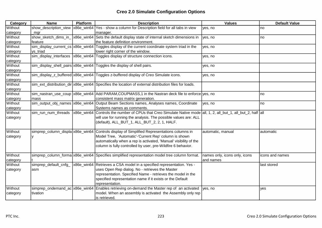
Creo 2.0 Simulate Configuration Options
Category Name Platform Description Values Default Value
Without
category
show_description_view
_mgr
x86e_win64 Yes - show a column for Description field for all tabs in view
manager.
yes, no no
Without
category
show_sketch_dims_in_
feature
x86e_win64 Sets the default display state of internal sketch dimensions in
the feature definition environment.
yes, no no
Without
category
sim_display_current_cs
ys_triad
x86e_win64 Toggles display of the current coordinate system triad in the
lower right corner of the window.
yes, no
Without
category
sim_display_interfaces x86e_win64 Toggles display of structure connection icons. yes, no
Without
category
sim_display_shell_pairs x86e_win64 Toggles the display of shell pairs. yes, no
Without
category
sim_display_z_buffered x86e_win64 Toggles z-buffered display of Creo Simulate icons. yes, no
Without
category
sim_ext_distribution_dir x86e_win64 Specifies the location of external distribution files for loads.
Without
category
sim_nastran_use_coup
mass
x86e_win64 Add PARAM,COUPMASS,1 in the Nastran deck file to enforce
consistent mass matrix generation.
yes, no no
Without
category
sim_output_obj_names x86e_win64 Output Beam Sections names, Analyses names, Coordinate
Systems names as comments.
yes, no no
Without
category
sim_run_num_threads x86e_win64 Controls the number of CPUs that Creo Simulate Native mode
will use for running the analysis. The possible values are: ALL
(default), ALL_BUT_1, ALL_BUT_2, 2, 1, HALF.
all, 1, 2, all_but_1, all_but_2, half all
Without
category
simprep_column_displa
y
x86e_win64 Controls display of Simplified Representations columns in
Model Tree, 'Automatic'-'Current Rep' column is shown
automatically when a rep is activated, 'Manual' visibility of the
column is fully controlled by user, pre-Wildfire 6 behavior.
automatic, manual automatic
Without
category
simprep_column_forma
t
x86e_win64 Specifies simplified representation model tree column format. names only, icons only, icons
and names
icons and names
Without
category
simprep_default_cnfg_
asm
x86e_win64 Retrieves a CSA model in a specified representation. Yes -
uses Open Rep dialog. No - retrieves the Master
representation. Specified Name - retrieves the model in the
specified representation name if it exists or the Default
representation.
last stored
Without
category
simprep_ondemand_ac
tivation
x86e_win64 Enables retrieving on-demand the Master rep of an activated
model. When an assembly is activated the Assembly only rep
is retrieved.
yes, no yes
PTC Inc. 223 Creo 2.0 Simulate Configuration Options
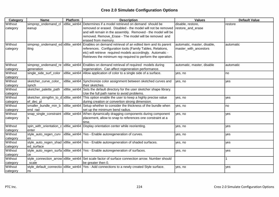
Creo 2.0 Simulate Configuration Options
Category Name Platform Description Values Default Value
Without
category
simprep_ondemand_cl
eanup
x86e_win64 Determines if a model retrieved on demand should be
removed or erased. Disabled - the model will not be removed
and will remain in the assembly. Removed - the model will be
removed. Remove_Erase - The model will be removed and
erased from memory.
disable, restore,
restore_and_erase
restore
Without
category
simprep_ondemand_ed
iting
x86e_win64 Enables on demand retrieval of an edited item and its parent
references. Configuration tools (Family Tables, Relations,
etc) will retrieve required models accordingly. Automatic -
Retrieves the minimum rep required to perform the operation.
automatic, master, disable,
master_with_ancestors
automatic
Without
category
simprep_ondemand_re
generation
x86e_win64 Enables on demand retrieval of required models during
regeneration. Can affect regeneration performance.
automatic, master, disable automatic
Without
category
single_side_surf_color x86e_win64 Allow application of color to a single side of a surface. yes, no no
Without
category
sketcher_curve_color_
synch
x86e_win64 Synchronize color assignment between sketched curves and
their sketches.
yes, no yes
Without
category
sketcher_palette_path x86e_win64 Sets the default directory for the user sketcher shape library.
Use the full path name to avoid problems.
Without
category
sketcher_strngthn_to_d
ef_dec_pl
x86e_win64 This option enable the user to keep a highly precise value
during creation or convertion strong dimension.
yes, no yes
Without
category
smaller_bundle_min_b
end_rad
x86e_win64 Setup whether to consider the thickness of the bundle when
set up the minimum bend radius.
yes, no no
Without
category
snap_single_constraint
s
x86e_win64 When dynamically dragging components during component
placement, allow to snap to references one constraint at a
time.
yes, no yes
Without
category
spin_with_orientation_c
enter
x86e_win64 Display orientation center while reorienting. yes, no yes
Without
category
style_auto_regen_curv
es
x86e_win64 Yes - Enable autoregeneration of curves. yes, no yes
Without
category
style_auto_regen_shad
ed_surface
x86e_win64 Yes - Enable autoregeneration of shaded surfaces. yes, no yes
Without
category
style_auto_regen_surfa
ce
x86e_win64 Yes - Enable autoregeneration of surfaces. yes, no yes
Without
category
style_connection_arrow
_scale
x86e_win64 Set scale factor of surface connection arrow. Number should
be greater then 0.
1
Without
category
style_default_connectio
ns
x86e_win64 Yes - Add connections to a newly created Style surface. yes, no yes
PTC Inc. 224 Creo 2.0 Simulate Configuration Options

Creo 2.0 Simulate Configuration Options
Category Name Platform Description Values Default Value
Without
category
style_display_grid x86e_win64 Yes - Display grid for active datum plane. yes, no yes
Without
category
style_grid_spacing x86e_win64 Set the number of lines to display on the grid. Number should
be equal or greater than 2.
5
Without
category
style_state_transparen
cy
x86e_win64 Set the value of transparency for components set to
"Transparent" in style state. Value must be between 0 and
100.
70
Without
category
style_surface_mesh_di
splay
x86e_win64 On - Display surfaces mesh. Off - Do not display surfaces
mesh. Off When Shaded - Display surfaces mesh except
when shaded.
off, on, off when shaded off when shaded
Without
category
style_surface_mesh_q
uality
x86e_win64 Sets the quality of the surface mesh. Values range is between
0.1 to 10.
1
Without
category
template_cnfg_asm x86e_win64 Specifies the default configurable assembly template file. Use
full pathname to avoid problems.
inlbs_csa.asm
Without
category
template_esrasm x86e_win64 Specifies the designated template ESR assembly. Use full
path to avoid problems.
inlbs_asm_esr.asm
Without
category
template_layout x86e_win64 Specifies the default layout template file. Use full pathname to
avoid problems.
Without
category
tk_enable_ribbon_cust
om_save
x86e_win64 Enable storing the Auxiliary Application User Interface
customization
yes, no no
Without
category
tool_motion_list_length x86e_win64 Controls the number of rows visible in the tool motion list
without scrolling. This value is applied to dashboard based
NC Steps.
7
Without
category
trace_thru_splice_conn
ector
x86e_win64 Report the from/to connectors of cables passing through
splices correctly.
yes, no no
Without
category
travel_bounds_display x86e_win64 Enable travel bounds display. yes, no no
Without
category
travel_bounds_transpar
ency
x86e_win64 Transparency value for machine bound display. 0.8
Without
category
trngrv_roundtool_nobac
kcut
x86e_win64 Yes - Groove turning using round tool generates no back cut
motion for profile pass.
yes, no no
Without
category
upd_param_on_retr_m
ark_modified
x86e_win64 Allows/disallows mark model as changed if as a result of
mass properties/relations calculation during retrieval some
parameter values are changed.
yes, no no
Without
category
use_master_for_bad_di
sp_reps
x86e_win64 Yes to retrieve master rep when graphics rep has no display
data.
yes, no no
Without
category
use_web_page_font_in
_reports
x86e_win64 Controls whether HTML reports use the browser's standard
fonts.
yes, no no
PTC Inc. 225 Creo 2.0 Simulate Configuration Options
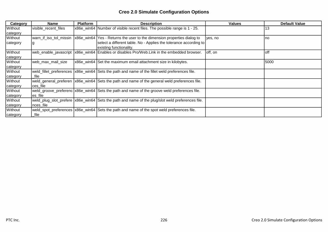
Creo 2.0 Simulate Configuration Options
Category Name Platform Description Values Default Value
Without
category
visible_recent_files x86e_win64 Number of visible recent files. The possible range is 1 - 25. 13
Without
category
warn_if_iso_tol_missin
g
x86e_win64 Yes - Returns the user to the dimension properties dialog to
select a different table. No - Applies the tolerance according to
existing functionality.
yes, no no
Without
category
web_enable_javascript x86e_win64 Enables or disables Pro/Web.Link in the embedded browser. off, on off
Without
category
web_max_mail_size x86e_win64 Set the maximum email attachment size in kilobytes. 5000
Without
category
weld_fillet_preferences
_file
x86e_win64 Sets the path and name of the fillet weld preferences file.
Without
category
weld_general_preferen
ces_file
x86e_win64 Sets the path and name of the general weld preferences file.
Without
category
weld_groove_preferenc
es_file
x86e_win64 Sets the path and name of the groove weld preferences file.
Without
category
weld_plug_slot_prefere
nces_file
x86e_win64 Sets the path and name of the plug/slot weld preferences file.
Without
category
weld_spot_preferences
_file
x86e_win64 Sets the path and name of the spot weld preferences file.
PTC Inc. 226 Creo 2.0 Simulate Configuration Options

Creo 1.0 to Creo 2.0 Simulate Configuration Option Changes
Category Name Platform Status Description Values Default Value
Application
Programming
Interfaces
web_enable_subscription x86e_win64 DELETED Enable the subscription mechanism for Connections yes, no yes
Assembly grv_default_view x86e_win64 NEW Sets the default view the reference view starts with -
Dependencies or References.
references,
dependencies
references
Assembly show_interference_in_secti
ons
x86e_win64 NEW Yes - Interference will be shown automatically, No -
interference will not be shown automatically.
yes, no no
Data Exchange afx_enabled x86e_win64 NEW Loads EFX application. yes, no no
Data Exchange board_bend_notes_dflt_dis
play
x86e_win64 NEW Defines the default state of board bend note display. yes, no yes
Data Exchange board_bend_notes_directio
n_down
x86e_win64 NEW Defines the down direction symbol for board bend
notes.
default
Data Exchange board_bend_notes_directio
n_up
x86e_win64 NEW Defines the up direction symbol for board bend notes.
Data Exchange board_bend_notes_order x86e_win64 NEW Defines the fields order for board bend notes. &type&direction&angle
Data Exchange board_bend_notes_type_fo
rmed
x86e_win64 NEW Defines the formed symbol for board bend notes. default
Data Exchange board_bend_notes_type_ro
lled
x86e_win64 NEW Defines the rolled symbol for board bend notes. default
Data Exchange board_bend_table_director
y
x86e_win64 NEW Will be used to set the bend allowance table only.
Sets the default directory of the board bend allowance
table files. If not set, the system supplied bend tables
are used. Use the full name and path to avoid
problems.
Data Exchange board_design_rules_directo
ry
x86e_win64 NEW Will be used to set the design rules file folder only.
Will be used by the design rules manager. Sets the
default directory of the board design rules files. Use
the full name and path to avoid problems.
Data Exchange board_drive_bend_by_para
meters
x86e_win64 NEW Board bend radius and bend angle values and bend
dimension location will be driven by feature-level
relations to board parameters.
yes, no no
Data Exchange board_drive_tools_by_para
meters
x86e_win64 NEW Drives the board options and values by feature-level
relations to board parameters.
yes, no yes
Data Exchange board_flat_shape_sketches
_dir
x86e_win64 NEW Sets path to directory that contains the Flat shapes.
PTC Inc. 227 Creo 1.0 to Creo 2.0 Simulate Configuration Option Changes
Creo 1.0 to Creo 2.0 Simulate Configuration Option Changes
Category Name Platform Status Description Values Default Value
Data Exchange board_parameters_director
y
x86e_win64 NEW Specifies the directory to save/retrieve board
parameters files. Use full name and path to avoid
problems.
Data Exchange ecadcollab_auto_redef_are
as
x86e_win64 NEW Automatically redefine ECAD Areas affected by
collaboration changes
yes, no yes
Data Exchange ecadcollab_auto_redef_co
mps
x86e_win64 NEW Automatically redefine components affected by
collaboration changes
yes, no yes
Data Exchange ecadcollab_auto_redef_hol
es
x86e_win64 NEW Automatically redefine holes affected by collaboration
changes
yes, no yes
Data Exchange ecadcollab_preview_level x86e_win64 NEW ECAD Collaboration preview Level full, partial, light partial
Data Exchange ecadcollab_scan_des_on_
area_chg
x86e_win64 NEW Check for affected objects resulting from ECAD
Areas collaboration changes
yes, no yes
Data Exchange ecadcollab_scan_des_on_
brd_chg
x86e_win64 NEW Check for affected objects resulting from board
collaboration changes
yes, no yes
Data Exchange ecadcollab_scan_des_on_c
omp_chg
x86e_win64 NEW Check for affected objects resulting from components
collaboration changes
yes, no yes
Data Exchange ecadcollab_scan_des_on_
hole_chg
x86e_win64 NEW Check for affected objects resulting from holes
collaboration changes
yes, no yes
Data Exchange ecadcollab_supp_failed_fe
ats
x86e_win64 NEW Suppress of failed features on Object changes yes, no yes
Data Exchange ecadcollab_suppress_cuts x86e_win64 NEW Automatically suppress cut features in case of board
collaboration changes
yes, no yes
Data Exchange efx_enabled x86e_win64 DELETED Loads EFX application. yes, no no
Data Exchange initial_board_bend_y_factor x86e_win64 NEW Specifies a value used to determine the natural bend
line for a board part. This value is always used for non-
cylindrical bends. It is used for regular bends only
when no bend table is specified.
0.5
Data Exchange intf_ug_version x86e_win64 CHANGE
D
Sets the version of Unigraphics interface. nx5, nx6, nx7 nx6,
nx7, nx8
nx5 nx6
Data Exchange pro_gplug_dir x86e_win64 CHANGE
D
Specifies the directory in which Granite application
plug-ins are located. Use the full pathname to avoid
problems.
<creo1.0_loadpoint>\x86e_win64\gpl
ugs\
<creo2.0_loadpoint>\x86e_win64\gpl
ugs\
Data Exchange template_boardpart x86e_win64 NEW Specify the model to use as the default new ECAD
board template.
PTC Inc. 228 Creo 1.0 to Creo 2.0 Simulate Configuration Option Changes

Creo 1.0 to Creo 2.0 Simulate Configuration Option Changes
Category Name Platform Status Description Values Default Value
Data Exchange template_new_ecadasm x86e_win64 NEW Specify the model to use as the default new ECAD
assembly template.
Data
Management
dm_simple x86e_win64 NEW Activate Simple Windchill Interaction yes, no no
Drawing bom_format x86e_win64 CHANGE
D
Sets the BOM format file to be used for a customized
BOM. Specify name and path.
<creo1.0_loadpoint>\text\format.bft
<creo2.0_loadpoint>\text\format.bft
Drawing drawing_setup_file x86e_win64 CHANGE
D
Sets the default drawing setup file option values for
your Creo Parametric session, otherwise, the system
uses the default drawing setup file option values.
Certain parameters in the file are valid only if you
have a license for Pro/DETAIL.
<creo1.0_loadpoint>\text\prodetail.dtl
<creo2.0_loadpoint>\text\prodetail.dtl
Drawing drawing_warn_if_flex_featu
re
x86e_win64 NEW Display a warning dialog upon opening a drawing with
models that contain flexible features advising users
that annotations may be out of date and should be
verified.
yes, no yes
Drawing preferred_export_format x86e_win64 CHANGE
D
Set the preferred export format for Drawings and
Layouts. Set the default preferred export file type for
export from drawings.
cgm, tiff, iges, dxf,
step, pdf, dwg,
medusa, stheno
Drawing pro_palette_dir x86e_win64 CHANGE
D
Sets the default directory for drawing symbol palette
files.
<creo1.0_loadpoint>\symbols\palette\
<creo2.0_loadpoint>\symbols\palette\
Electromechani
cal
cabling_split_multi_pnt_loc
s
x86e_win64 NEW Setup whether to convert multiple-location features
into single location features.
yes, no yes
Electromechani
cal
display_duplicate_harness_
msg
x86e_win64 NEW Display warning message when duplicate harness are
identified in the same assembly.
yes, no yes
Environment save_section_surfaces x86e_win64 NEW Yes - Save section surfaces with models. No - Do not
save section surfaces with models.
yes, no yes
File Storage &
Retrieval
pro_font_dir x86e_win64 CHANGE
D
Sets the default font directory (Creo Parametric will
load all fonts in this directory into the drawing
regardless of the contents of the system and working
directories).
<creo1.0_loadpoint>\text\fonts\
<creo2.0_loadpoint>\text\fonts\
File Storage &
Retrieval
pro_surface_finish_dir x86e_win64 CHANGE
D
Sets the default directory for your user-defined
surface finish symbols. Use the full pathname to avoid
problems.
<creo1.0_loadpoint>\symbols\surffins
\
<creo2.0_loadpoint>\symbols\surffins
\
PTC Inc. 229 Creo 1.0 to Creo 2.0 Simulate Configuration Option Changes

Creo 1.0 to Creo 2.0 Simulate Configuration Option Changes
Category Name Platform Status Description Values Default Value
File Storage &
Retrieval
set_model_types_to_save x86e_win64 CHANGE
D
Determines which model types are used in the Save
Changed command. The format is a list of extensions
separated by spaces.
asm prt drw sec mfg gph ipf asm prt
drw sec mfg gph ipf cem
File Storage &
Retrieval
template_module x86e_win64 NEW Specifies the default module template file. Use full
pathname to avoid problems.
inlbs_asm_module.asm
Manufacturing ncmdl_bar_stock_part_pat
h
x86e_win64 CHANGE
D
Sets path for storage and retrieval of stock instances
for creating workpiece in NC Model. Specify full path,
including part name, to avoid problems.
<creo1.0_loadpoint>\text\ncmdl_data
\ncmdl_bar.prt
<creo2.0_loadpoint>\text\ncmdl_data
\ncmdl_bar.prt
Manufacturing ncmdl_billet_stock_part_pa
th
x86e_win64 CHANGE
D
Sets path for storage and retrieval of stock instances
for creating workpiece in NC Model. Specify full path,
including part name, to avoid problems.
<creo1.0_loadpoint>\text\ncmdl_data
\ncmdl_billet.prt
<creo2.0_loadpoint>\text\ncmdl_data
\ncmdl_billet.prt
Manufacturing
Without
category
dm_nc_process x86e_win64 CHANGE
D
Sets output of NC process information as content on
the NC Assembly CAD Document in XML Format.
Yes - Outputs the file whenever CAD Document is
Saved. No - Does not output the file.
yes, no no
Mechanica fem_default_solver x86e_win64 CHANGE
D
Specifies default solver. ansys, nastran ansys,
nastran, nei_nastran
Mechanica fem_solver_time_limit x86e_win64 CHANGE
D
For NASTRAN solution, uses this option to interrupt
the solver after the specified time limit. The default
value is 60 minutes. Interrupt the Nastran solver
after the specified time limit in minutes using the
TIME executive card. A negative number directs the
solver to use its own default. The default value of this
option is -1.
60 -1
Mechanica pro_nei_nastran_path x86e_win64 NEW Specifies the path to the NEi Nastran executable.
Mechanica sim_modal_stress_superpo
sition
x86e_win64 NEW If set to yes, use the modal stress superposition
method to compute the stress results. If set to no, use
the superconvergent stress recovery method.
yes, no yes
Mechanica sim_wf5_fastener_fix_sepa
ration
x86e_win64 NEW Sets the value of Fix Separation for fasteners created
in Wildfire 5.0 or earlier with Fix Separation set to
Auto.
yes, no, default default
PTC Inc. 230 Creo 1.0 to Creo 2.0 Simulate Configuration Option Changes

Creo 1.0 to Creo 2.0 Simulate Configuration Option Changes
Category Name Platform Status Description Values Default Value
Model Display animate_component_place
ment
x86e_win64 NEW Animate the transition between component states in
placement.
yes, no yes
Model Display blended_transparency x86e_win64 CHANGE
D
Yes - Transparent colors will appear using alpha
blending (if supported) when the model is shaded.
yes, no yes, no,
independent
yes
Model Display model_detail_options_file x86e_win64 CHANGE
D
Sets the path to the file which contains the default
model detail option values for new models.
<creo1.0_loadpoint>\text\3d_inch.dtl
<creo2.0_loadpoint>\text\3d_inch.dtl
Photorender default_scene_filename x86e_win64 CHANGE
D
Complete path to the scene file to be used as default
scene file.
<creo1.0_loadpoint>\graphic-
library\scenes\/creo_default_scene.s
cn <creo2.0_loadpoint>\graphic-
library\scenes\/creo_default_scene.s
cn
Piping isogen_attribute_map_file x86e_win64 CHANGE
D
Specifies the mapping between isogen parameter and
attribute name.
<creo1.0_loadpoint>\text\piping_data
\isodata\isogen_attribute_map.ptd
<creo2.0_loadpoint>\text\piping_data
\isodata\isogen_attribute_map.ptd
Piping isogen_endtype_map_file x86e_win64 CHANGE
D
Specify name of file mapping Pro/Piping endtypes
with ISOGEN endtypes
<creo1.0_loadpoint>\text\piping_data
\isodata\isogen_endtype_map.ptd
<creo2.0_loadpoint>\text\piping_data
\isodata\isogen_endtype_map.ptd
Piping isogen_nominal_size_map
_file
x86e_win64 CHANGE
D
Specify name of file mapping Pro/Piping Size with
Nominal Sizes in MM and Inches
<creo1.0_loadpoint>\text\piping_data
\isodata\isogen_nominal_size_map.p
td
<creo2.0_loadpoint>\text\piping_data
\isodata\isogen_nominal_size_map.p
td
PTC Inc. 231 Creo 1.0 to Creo 2.0 Simulate Configuration Option Changes

Creo 1.0 to Creo 2.0 Simulate Configuration Option Changes
Category Name Platform Status Description Values Default Value
Piping isogen_symbol_map_file x86e_win64 CHANGE
D
Specify name of file for mapping Pro/Piping selection
names with ISOGEN symbol keys (SKEY)s
<creo1.0_loadpoint>\text\piping_data
\isodata\isogen_symbol_map.ptd
<creo2.0_loadpoint>\text\piping_data
\isodata\isogen_symbol_map.ptd
Piping pipeline_assembly_library_
dir
x86e_win64 CHANGE
D
Sets the default pipeline assembly library directory. <creo1.0_loadpoint>\text\piping_data
\pipelinelib\
<creo2.0_loadpoint>\text\piping_data
\pipelinelib\
Piping piping_appearance_map_fil
e
x86e_win64 CHANGE
D
Sets the default piping appearance map filename. <creo1.0_loadpoint>\text\piping_data
\master_catalog\piping_appearance.
map
<creo2.0_loadpoint>\text\piping_data
\master_catalog\piping_appearance.
map
Piping piping_bolt_nut_select_file x86e_win64 CHANGE
D
Piping bolts and nuts selection file. <creo1.0_loadpoint>\text\piping_data
\master_catalog\piping_bolt_nut_sele
ct.ptd
<creo2.0_loadpoint>\text\piping_data
\master_catalog\piping_bolt_nut_sele
ct.ptd
Piping piping_end_compatibility_fil
e
x86e_win64 CHANGE
D
Sets the default piping end compatibility filename. <creo1.0_loadpoint>\text\piping_data
\master_catalog\piping_end_compati
bility.ptd
<creo2.0_loadpoint>\text\piping_data
\master_catalog\piping_end_compati
bility.ptd
Piping piping_fitt_category_map_fi
le
x86e_win64 CHANGE
D
Sets the default piping fitting category map filename. <creo1.0_loadpoint>\text\piping_data
\sample_project\piping_fitt_category_
map.ptd
<creo2.0_loadpoint>\text\piping_data
\sample_project\piping_fitt_category_
map.ptd
Piping piping_fitt_library_dir x86e_win64 CHANGE
D
Sets the default piping fitting library directory. <creo1.0_loadpoint>\text\piping_data
\fittinglib\
<creo2.0_loadpoint>\text\piping_data
\fittinglib\
PTC Inc. 232 Creo 1.0 to Creo 2.0 Simulate Configuration Option Changes
Creo 1.0 to Creo 2.0 Simulate Configuration Option Changes
Category Name Platform Status Description Values Default Value
Piping piping_insulation_dir_file x86e_win64 CHANGE
D
Sets the default piping insulation directory filename. <creo1.0_loadpoint>\text\piping_data
\sample_project\piping_insulation_dir
.ptd
<creo2.0_loadpoint>\text\piping_data
\sample_project\piping_insulation_dir
.ptd
Piping piping_manufacture_dir_file x86e_win64 CHANGE
D
Sets the default piping manufacture directory
filename.
<creo1.0_loadpoint>\text\piping_data
\master_catalog\piping_manufacture
_dir.ptd
<creo2.0_loadpoint>\text\piping_data
\master_catalog\piping_manufacture
_dir.ptd
Piping piping_material_file x86e_win64 CHANGE
D
Sets the default piping material filename. <creo1.0_loadpoint>\text\piping_data
\master_catalog\piping_material.ptd
<creo2.0_loadpoint>\text\piping_data
\master_catalog\piping_material.ptd
Piping piping_mcat_dir x86e_win64 CHANGE
D
Sets the default piping master catalog directory. <creo1.0_loadpoint>\text\piping_data
\master_catalog\
<creo2.0_loadpoint>\text\piping_data
\master_catalog\
Piping piping_mcat_dir_file x86e_win64 CHANGE
D
Sets the default piping master catalog directory
filename.
<creo1.0_loadpoint>\text\piping_data
\master_catalog\piping_mcat_dir.ptd
<creo2.0_loadpoint>\text\piping_data
\master_catalog\piping_mcat_dir.ptd
Piping piping_project_data_dir x86e_win64 CHANGE
D
Sets the default Project data directory. <creo1.0_loadpoint>\text\piping_data
\sample_project\
<creo2.0_loadpoint>\text\piping_data
\sample_project\
Piping piping_spec_dir_file x86e_win64 CHANGE
D
Sets the default piping specification directory
filename.
<creo1.0_loadpoint>\text\piping_data
\sample_project\piping_spec_dir.ptd
<creo2.0_loadpoint>\text\piping_data
\sample_project\piping_spec_dir.ptd
PTC Inc. 233 Creo 1.0 to Creo 2.0 Simulate Configuration Option Changes
Creo 1.0 to Creo 2.0 Simulate Configuration Option Changes
Category Name Platform Status Description Values Default Value
Piping units_system_dic_file x86e_win64 CHANGE
D
Specifies the file containing the mapping for MCAT
filename and units.
<creo1.0_loadpoint>\text\piping_data
\master_catalog\piping_units_system
_dic_file.ptd
<creo2.0_loadpoint>\text\piping_data
\master_catalog\piping_units_system
_dic_file.ptd
Printing &
Plotting
plot_carberry_extends x86e_win64 CHANGE
D
When plotting to a raster format (jpg, tiff, etc), setting
this option to YES will ignore the view border and
produce output sized to the smallest rectangle that
includes the drawing items. When plotting to a
raster format (jpg, tiff, etc), set to YES to ignore the
view border and produce output sized to the smallest
rectangle that includes the drawing items.
yes, no no
Sheetmetal material_upd_smt_bend_ta
ble
x86e_win64 CHANGE
D
Defines whether assignment of material to the model
via Pro/Toolkit will overwrite existing bend table data
and y factor value. Always Replace - Overwrites
existing data. Never Replace - Keeps existing data
Defines whether assignment of material to the model
via Creo Toolkit will overwrite existing bend table data
and y factor value. Always Replace - Overwrites
existing data. Never Replace - Keeps existing data
always_replace,
never_replace
always_replace
Sheetmetal smt_bend_notes_dflt_displ
ay
x86e_win64 CHANGE
D
Define the default state of Bend Note display
(sheetmetal Mode) Define the default state of bend
note display (sheetmetal mode)
yes, no yes
Sheetmetal smt_bend_notes_direction_
down
x86e_win64 CHANGE
D
Define the Down Direction symbol for Bend Notes
(sheetmetal Mode) Define the down direction
symbol for bend notes (sheetmetal mode)
default
Sheetmetal smt_bend_notes_direction_
up
x86e_win64 CHANGE
D
Define the Up Direction symbol for Bend Notes
(sheetmetal Mode) Define the up direction symbol
for bend notes (sheetmetal mode)
default
Sheetmetal smt_bend_notes_order x86e_win64 CHANGE
D
Define the Fields Order for Bend Notes (sheetmetal
Mode) Define the fields order for bend notes
(sheetmetal mode)
&type&direction&angle
Sheetmetal smt_bend_notes_type_for
med
x86e_win64 CHANGE
D
Define the Formed symbol for Bend Notes
(sheetmetal Mode) Define the formed symbol for
bend notes (sheetmetal mode)
default
PTC Inc. 234 Creo 1.0 to Creo 2.0 Simulate Configuration Option Changes

Creo 1.0 to Creo 2.0 Simulate Configuration Option Changes
Category Name Platform Status Description Values Default Value
Sheetmetal smt_bend_notes_type_rolle
d
x86e_win64 CHANGE
D
Define the Rolled symbol for Bend Notes (sheetmetal
Mode) Define the rolled symbol for bend notes
(sheetmetal mode)
default
System auto_traceback x86e_win64 CHANGE
D
When set to yes, traceback.log file will be generated
when fatal error occurs. "always": a traceback file
will be generated when a fatal error occurs. "yes",
"ask": ask the user whether to generate a traceback.
"no", "never": no traceback will be generated.
yes, no, never, ask,
always
no always
System web_browser_homepage x86e_win64 CHANGE
D
Enter location of Creo Parametric browser home
page.
<creo1.0_loadpoint>\help\usascii\res
ource_center_index.html
<creo2.0_loadpoint>\help\usascii\res
ource_center_index.html
User Interface
Without
category
enable_learning_connector x86e_win64 CHANGE
D
Enable the Learning Connector, which provides
context specific access to videos, training, help
topics, and technical support content. When enabled,
the Learning Connector is added to the ribbon bar
next to Help.
yes, no no
Without
category
assemble_module_in_rep x86e_win64 NEW Retrieves the assembled module to CSA in a
specified representation.
representative module variant
Without
category
auto_eval_current_cnfg_rul
e
x86e_win64 NEW If the option is "yes" simplified representation would
be updated each time on retrieve/regeneration if it
contains current configuration rule.
yes, no yes
Without
category
constraint_reference_redefi
ne
x86e_win64 CHANGE
D
keep_constraint_type - Adjusts the component
position to keep the same constraint type.
reset_constraint_type - Automatically changes the
constraint type to keep the position of the component.
keep_constraint_type
,
reset_constraint_type
keep_constraint_type
Without
category
data_sharing_gen_notificati
on
x86e_win64 DELETED off, on off
Without
category
default_comp_module_geo
m_scope
x86e_win64 NEW Set the specified Shared Geometry reference control
conditions to newly added components for
configurable structure.
all, none, pg, tagged tagged
Without
category
default_obj_module_constr
_scope
x86e_win64 NEW Set the specified Shared Placement reference control
conditions to newly created models for configurable
structure if template models were not used.
all, none, interfaces,
tagged
tagged
PTC Inc. 235 Creo 1.0 to Creo 2.0 Simulate Configuration Option Changes

Creo 1.0 to Creo 2.0 Simulate Configuration Option Changes
Category Name Platform Status Description Values Default Value
Without
category
default_obj_module_geom
_scope
x86e_win64 NEW Set the specified Shared Geometry reference control
conditions to newly created models for configurable
structure modules if template models were not used.
all, none, pg, tagged all
Without
category
default_ref_current_module
_vrnt
x86e_win64 NEW Allow references to current design solution only. yes, no yes
Without
category
depthcue_always x86e_win64 DELETED Depth cue aids in visualizing a wireframe model. With
depth cue enabled, wireframe lines become darker as
they extend into the screen and lighter as they extend
towards the screen. Depth cue is supported only by
the appropriate graphics hardware.
yes, no yes
Without
category
depthcue_value x86e_win64 DELETED Aids in visualizing a wireframe model. With depth cue
enabled, this option specifies the default percentage
of depthcue used. Depth cue is supported only by the
appropriate graphics hardware.
Without
category
display_combined_views x86e_win64 NEW Display combined view tabs by default yes, no no
Without
category
display_images x86e_win64 NEW Display images outside of Style feature yes, no yes
Without
category
dm_enable_impex_attribut
es
x86e_win64 NEW yes, no no
Without
category
edge_tess_quality x86e_win64 NEW Set the accuracy level for arc tessllation. high, medium, low low
Without
category
enable_fsaa x86e_win64 NEW Enable OpenGL full screen anti-aliasing. off, 2, 4, 8, 16, 32 off
Without
category
enable_obsoleted_features x86e_win64 NEW yes, no no
Without
category
enable_sociallink x86e_win64 NEW Allow Windchill SocialLink to connect with Creo
Parametric. When enabled SocialLink commands will
be added to the Application Menu and the Ribbon bar.
Enter "Yes" to enable SocialLink, and "No" to disable
it
yes, no yes
Without
category
intf3d_out_catia_v5_versio
n
x86e_win64 CHANGE
D
Allows the user to switch between the default and
alternate converter version for export to CATIA V5
16, 17, 18, 19, 20 16,
17, 18, 19, 20, 21, 22
16
PTC Inc. 236 Creo 1.0 to Creo 2.0 Simulate Configuration Option Changes

Creo 1.0 to Creo 2.0 Simulate Configuration Option Changes
Category Name Platform Status Description Values Default Value
Without
category
layout_guides x86e_win64 CHANGE
D
Yes - shows all guides; No - hides all guides
Enable/Disable layout guides.
yes, no yes
Without
category
lda_prefix_in_basic_dim_b
ox
x86e_win64 NEW Add prefix to basic box while converting the
dimension to basic.
yes, no no
Without
category
manikin_drag_legacy_rotat
e
x86e_win64 CHANGE
D
controls whether to rotate around axis manikin drag
mode invokes the old rotate version (or the forward
kinematics new version Controls the Manikin Rotate
Around Axis drag mode: Legacy (YES) or direct joint
angle control (NO)
yes, no no
Without
category
mfg_cl_euc_japanese_enc
ode
x86e_win64 NEW Yes - Output cl-file Japanese characters in EUC
encoding.
yes, no no
Without
category
module_variant_cross_refs x86e_win64 NEW Allow references between design solutions in Module yes, no no
Without
category
open_builder_in_mt_mode x86e_win64 NEW Open the variant builder in Model Tree Selection
mode
yes, no no
Without
category
ptc_manikin_comforts_path x86e_win64 NEW Sets the default directory for the Creo Parametric
manikin comfort angles. You must restart Creo
Parametric for the change to take effect.
Without
category
ptc_manikin_library_path x86e_win64 CHANGE
D
Sets the default directory for the Creo Parametric
manikin library (or custom manikin libraries you built
containing the proper index menu files). Use the full
path name to avoid problems. You must restart Creo
Parametric for the change to take effect.
<creo1.0_loadpoint>\manikin_lite\
<creo2.0_loadpoint>\manikin_lite\
Without
category
quick_print_plotter_config_f
ile
x86e_win64 CHANGE
D
Specify the path and name of the default plotter
config file to be used by the File > Quick Print
command. Specify the path and name of the default
plotter config file to be used by the File > Quick
Drawing command.
Without
category
reroute_affected_children x86e_win64 NEW Affected children when setting Current solution. none, auto, selective selective
Without
category
show_affected_children_di
alog
x86e_win64 NEW Do not invoke dialog for setting Current solution. yes, no yes
PTC Inc. 237 Creo 1.0 to Creo 2.0 Simulate Configuration Option Changes

Creo 1.0 to Creo 2.0 Simulate Configuration Option Changes
Category Name Platform Status Description Values Default Value
Without
category
simprep_default_cnfg_asm x86e_win64 NEW Retrieves a CSA model in a specified representation.
Yes - uses Open Rep dialog. No - retrieves the
Master representation. Specified Name - retrieves the
model in the specified representation name if it exists
or the Default representation.
last stored
Without
category
single_side_surf_color x86e_win64 NEW Allow application of color to a single side of a surface. yes, no no
Without
category
template_cnfg_asm x86e_win64 NEW Specifies the default configurable assembly template
file. Use full pathname to avoid problems.
inlbs_csa.asm
Without
category
template_config_asm x86e_win64 DELETED Specifies the default configurable assembly template
file. Use full pathname to avoid problems.
Without
category
template_container x86e_win64 DELETED Specifies the default container template file. Use full
pathname to avoid problems.
Without
category
tool_motion_list_length x86e_win64 NEW Controls the number of rows visible in the tool motion
list without scrolling. This value is applied to
dashboard based NC Steps.
7
Without
category
tracesketch x86e_win64 DELETED Display images outside of Style feature yes, no yes
PTC Inc. 238 Creo 1.0 to Creo 2.0 Simulate Configuration Option Changes