crack propagation tests on2024-t3 unstiffened aluminium...
TRANSCRIPT

C.P. No. 952
MINISTRY OF TECHNOLOGY
AERONAUTICAL RESEARCH COUNCIL
CURRENT PAPERS
Crack Propagation Tests on 2024-T3Unstiffened Aluminium Alloy Panels
of Various Length-Width RatiosbY
T. 1. Carter
LONDON: HER MAJESTY’S STATIONERY OFFICE
1967
PRICE 6s 6d NET


U.D.C. No. 629.13.ol2.1 : 6.zg.13.ol2.y : 539.388.1 :539.2'19.2 : 620.1-p3.3 : 669.715415
C.P. No.95PNovember 1966
by
T. J. Carter
Panels of ZO&Tj clad material of one width and of four length-widthratios were tested under constant am&itude fatigue loads in tension. Varia-tions were observed in the rate of crack growth with change of length-widthratio. The variations are greatest at the highest stress level tested. Theresults for panels of small length-;vidth retie were influenced by the proximityof the end attachments to the test se&ion. Information obtained from staticlon&.tud.inal strain measurements :vas generally in accord with the results ofthe crack growth tests.
It is recommended that tests performed to assess fatigue crack glnwthcharacteristics of materials in unstiPfened panels, should be made ::-ith alengtt:+nidth ratio about 2 ; 1.
* Replaces RAE. Tech. Zoport X0.66366 - A.X.C. 28966.


CONTEWS
? INTRODUCTION2 SPECIABNS3 LOADING CONDITIONS4 CR.ACKIUUS~'i!5 RBSULTS OF CRACK GRCXl'h TZSTS6 STRAIN BXSUR3W$IT TXSTS7 SU:Xi.‘J.RY OF XWJLTS8 ~:cWxJsIoNsTable ? Nominal chemical compnsition and static strength properties
of 2024-~3 materialTable 2 Results of fatigue crack growth tests at stress 5000
t4OW lb/in2Table 3 Results of fatigue crack groKth tests at stress 7500
~6000 lb/in*Table 4 Results of fatigue crack growth tests at stress 10000
28000 lb/in2
ReferenceIllustrations FiguresDetachable abstract cards
Specimen anti notchSide view of aparatus and specimenIncrease of crack length with cycles at stress 5000 24-000 lb/in2Increase of crack length with cycles at stress 7500 ~6000 lb/in2Increase of crack length with cycles at stress 20000 ~8000 lb/in2Variation of crack growth rate with crack length in panels ofdifferent length-width ratios at stress 5000 f4-000 lb/in2Variation of crack growth rate with crack length in panels ofdifferent length-width ratios at stress 7500 -1-6000 lb/in2Variation of crack growth rate with crack length in panels ofdifferent length-width ratios at s2res.s 10000 +&300 lb/in2Variation of crack growth rate with panel ratso at particularcrack lengths. Stress level 5000 9tOOO lb/inVariation of crack grotih rate with panel ratio at particularcrack lengths. Stress level 75GQ +6000 lb/in2Variation of crack growth rate with panel ratio at particularcrack lengths. Stress level 10000 &i;OGO lb/in2Positions of the strain gauges on the cracked and unsraclced panels
Page55667789
10
II
13
15
17I-16
Fig.12
345
6
7
8
9
1 0
1-l1 2

ILXiSTRATIONS (Contd)
Distribution of strain across the centre of untracked panels ofratios 1 :-land4:1
Distribution of strain across the centre of cracked panels ofratios '1 : 1, 2 : 1, 3 : 1 and 4 : 1Distribution of strain across a panel with a 4.5 inch crack, ona line 4% inches from the crackDistribu;ion of strain across a panel with a 4.5 inch crack, ona line 3g inches from the crack
43
14
15
-16

5
I INTRODUCTION
Design data on fatigue crack groxth in sheet material have been collectedfrom many independent sources. The data have been obtained from tests onpanels of various lengths, widths, thicknesses andzength-width ratios. The useof panels of such varied geometry may have introduoed scatter into the data.This paper presents the results of an investigation of the effect of panellength-width ratic at constant panel width and thickness in clad aluminiumalloy material to specification 2024X3. The tests were made on unstiffenedpanels of 0.080 inch thick material with central notches. Length-width ratiosof 1 : I, 2 : I, 3 : i and 4 : -l were used, the width being ?O inches in allcases. The tests were made with constant .sm@itude fluctuating tension. Threealternating stress levels were investigated, the ratio of alternating stressamplitude to mean stress remaining constant. The test results indicate thatthe length-width ratio of the panel may have a significant effect on the rateof growth of fatigue cracks rhich are scbjcctedto otherrrise nominally identicalconditions, and it is suggested that a length-width ratio of 2 : 1 might bestandard.ised for material assessment tests.
A limited investigation of the strain Zstribution in the vicinity of acrack showed that the magnitude of the strains varied as length-xi&h ratio waschanged, in a manner corresponding to that of the observed crack growth rates,
Specimens of four length-ividth ratios, 9 : ?, 2 : I, 3 : 1 and 4 : 1were tested*. These ratios were chose2 to cover the rsage normolly used toobtain crack growth data. All specimens, OS shown in X.g.q, were IO incheswide and 0.080 inch thick, beicg made from 20&t-T3 mzterisl u:ith centralnotches 0.5 inch long. ThL- gc:ometry of the notch is shoxn in Fig.1 being leftas finished by a saw, in order to ir,itixte c rzcks as quickly as possible. Toachieve accurate axiality of load, all bolt holes st the ends ware drilledthrough a jig.
The ends of the specimens were clomped by Q inch diameter high tensilesteel bolts, between 8 inch thick mild s-toe1 plates. The bolts wdre tightenedwith a torque of 30 lb/ft.
*For convenience these are referred to as I : 1 panels, 2 : ? panels, etc.in the subsequent text.

The material was supplied in 8 ft x 4 ft sheets and twelve panels were cutfrom each sheet, comprising three set s of the four different length-width ratios.In all cases the loading axis was pnrallcl to the direction of rolling.
The nominal chemical composition and static strength properties of thematerial are given in Table 1.
3 XDING CONDITIONS
The tests were made in an Avery Schenck Long base 20 ton machine ‘and thestresses applied to the panels were a constant amplitude sinusoidal stress ofamplitude Sa superimposed upon a mean stress of magnitude 1.25 Sa. The threevalues of Sa used were WOO lb/in2, 6000 lb/in2 and 8000 1b/'in2. The repeat-ability of a given stress level from specimen to specimen was 5279. Having setthe stress level, the machine control system permitted a variation of stresslevel with time of about 23%.
Tests were made at each value of Sa on three nomin,a.lly identical specimens,at each of the four length-width ratios. The twelve panels used at any onevalue of S were taken from one sheet of material so that any sheet-to-sheetavarlntlon in material properties vcould not invalidate the conclusions drawnon length-width ratio effect.
It was found during preliminary tests that peels of ratios 3 : 1 and4 : 1 vibrated in a direction perpendicular to the plane of the panel. Thevibration was prevented by applying slight clamping pressure along the twofree edges of the panel ;iiith felt pads on lengths of light steel angle section.
A photographic method was employed and a side view of the arrangement isshown in Fig.2. The method relied upon the fact that the surface of the sheet,having a smooth finish, formed a mirror on which the crack appeared as a darkline. Transparent plastic sheets with scales along their edges were placedalong each side of the crack so that the length could be recorded.
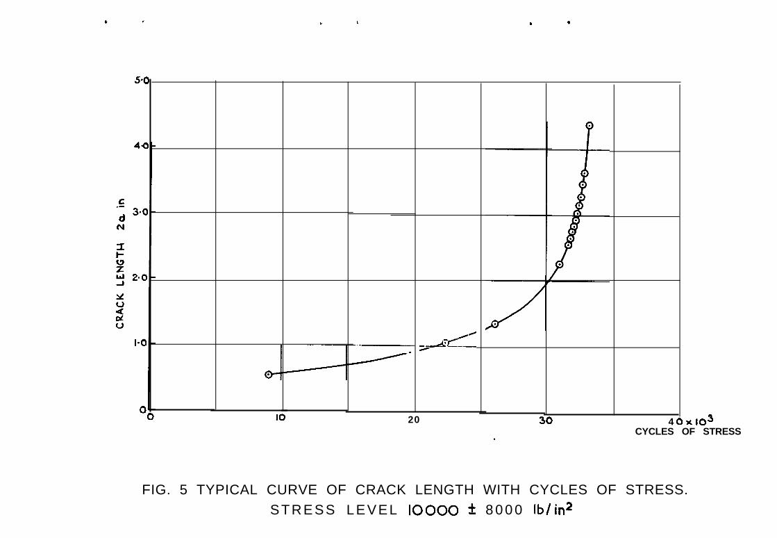
A counter of cycles vv'as arranged to appear in the photogra@. Thus eachframe of film recorded the number of cycles and associated crack le?@h. Inorder ts obtain adequate accuracy of resolution it ~~a.3 necessnry to use veryfine grain microfilm and a very short exposure from an electronic flash unitto minimise the effects of motion. About 45-20 photographs were taken in e,achtest at approximately equal increments of crack length. Typical cui'ves ofvnriattlon of crack length with cycles of stress are shown in Figs.3, 4 and 5.

7
5 RESULTS OF CRACK GRC-JTH TESTS
,
.
The data from the tests were nnclysed by a digital computer using amodification of the method of Rooke, Gunn, Bcal.lett and Bradshaw'. For eachtest the analysis prducea a tableof crack growth rates associated with parti-cular crack lengths. There was some scatter in the crack growth rates pm-
duced in the three nominally identical tests at each stress level and panelratio. The geometric means of the rates at particular crack lengths x:ere usedto plot a curve of mean crack growth rate against crack length. Fig.6 showscurves of this type for four panel ratios at a stress level of 5000 3-000 lb/in2.Figs.7 end 8 show the results at stress levels of 7500 +600o lb/in2 And10000 28000 lb/in2 respectively.
The graphs on Figs.q,lO and 11 show the variation of crack mwth ratewith change of length-width ratio for various crack lengths. In general thecrack growth rate is highest at length-width ratio 1 : I falling through ratio2 : 1 to a minimum between 2 : 1 and 3 : 1 and rising again to 4 : I. Thisvariation is most marked at the highest stress level(1CWO ZCOOO ib/in2 -Fig.11) where, taken as an averabe for all crack lengths, the minimum value isabout 6@ of the value at ratztio 1 : 1. At stress level 7500 2600~ lb/in2 -Fig.?O, for crack lengths from 1.2 inches to 4.8 inches inclusive, thevariation is less marked, the minimum value being on average about -iCr; of thevalue at ratio 1 : 1. At crack length 0.8 inch at this stress level scdter
in crack growth rate prevents the assessment of a general trend. At thelowest stress level, 5000 t4-000 lb/in2 - Pig.9, for crack lengths up to andincluding 3.2 inches, the minimum crack growth rate is on average about 75%of the value at ratio I : ?. Above a crack length of 3.2 inches at this stresslevel any general trend is difficult to find because of scatter in crackgrowth rates.
6 STRAIN MEZXJREMENT TESTS
Kensurements were made of static longitudinsl strain at the centre ofcracked and untracked panels to see if the trend in the variation of crackgrowth rate with change of length-width ratio could be associated iqith a trendin the variation of strain.
Strain gauges were positioned on 1 : I and 4 : I untracked panels asshown in 7ig.l2(a). Measurements were made of the increments of strain causedby an increment of applied stress from 1000 lb/in2 to 11000 lb/in'. Theresults are shown in Fig.13 and it is seen that the tistribution of strain atthe untracked test section is less uniform on the short panel, which over the

8
middle 3q~ of the width, has a strain % higher than the mean strain. It could
be inferred that conditions would be more severe on the 1 : 1 panel at least
in the early stages of crack growth. The proximity of the end fittings to the
centre of the panel will affect the relationship between the magnitudes of the
longitudinal strains and the transverse strains induced by Poisson's Ratio
effects. This may account for the fi.b9-t that the average longitudinal strain
is generally lower at the test section in the 1 : 1 panel than in the 4 : 1
panel under the same cLxia1 loads.
To determine the effect of panel ratio on the strain distribution near
the tip of a crack a second series of strain measurements was made on a cracked
panel, which was progressively shortened from r..kLtio 4 : ? to ratio ? : I. The
gauge positions are shown in Fig.l2(b), and 2gni.n measurements were irade of
increments of strain at these points caused by an increment of applied stress
from 1000 lb/in2 to 11000 lb/Ln2. The results are shown in Figs.llt, 15 and
16. It is seen in Fig.14 that at the test section, the strain in t!le -1 : 1
panel is higher than that in any of the others, and the strain in the 4 : 1
panel is higher than that in the 3 : I. Figs.35 and 16 ,also show that over
most of the panel width the strains at the other measurement sections ;LTe
highest in a panel of ratio 1 : 1. It may be nssLuned that the strain measure-
ments in the longitudinal direction alone give a general indication of the
local stress conditions in the panel. The crack propagation rates under the
test conditions which obtain in this work have been found to be dependent on
the third, or somewhat higher, power of stress and therefore the comparatively
small variations in strain could account for the observed variations in crack
propagation.
7 SUMh1&Y OF RESULTS
In view of the variations which have beet found in crack gromth rate
with panel ratio, anti the supporting evidence from the strain measurements, it
is considered that an effect of panel length-width ratio could contribute to
variations in measured crack growth rates in panels of varying geometries.
There is clearly a need for stanciardisntion of the geometry of test panels used
to obtain design data. Panels of length-width ratio as low as I : 1 are
undesirable because the distribution of strain at the test section is affected
by the constraint caused by the end plates. Similsrljr panels of high length-
width ratio are undesirable because panel resonance may complicate testing. It
is therefore recommended that a panel length-width ratio of about 2 : 'i should
be chosen.
.

9
8 CONCLUSIONS
Panels with four different length-width ratios have been tested at threestress levels, in nne material at nne thickness and width.
At the highest stress level tested (~0000 +8ooO lb/in2) crack growth
rate was fastest in panels of length-width ratio ? : 1 falling tr, 8 minimumfor a ratio between 2 : 'I and 3 : 1 and rising a little fqr ratio G : I, Theminimum is about 6% of the value measured at ratio I : 1. At the middle andlowest stress levels tested 3 similar but weaker trend is shown.
The results of the crack grnwth tests zre cnnfircled by ,an investigationof static longitudinal strain at the test section of cracked and uncrcckedpanels.
It is recrrmmended thr?t material assessment tests in crack propagationshould be done with a panel length-width r&in of Gout 2 : 1.

1 0
Table 1
Nominal chemical composition 2nd stztic strength properties0f 2024-~3 m,l;erial
Core CladdingElement
min. ;?'o max. $i max. $
Copper 3*8 4.9 0.10Magnesium 1.2 1.8
Mzngznese 0.30 0.9 0.50
Irvn 0.50Silicon 0.50 0.70
Chmmium 0.10
Zinc 0.25 0.10
Others, each 0.05 0.05Others, total 0.15 0.15
Aluminium I Remainder 99.30
Mechanical properties
Tensile strength minimum 62000 lb/in2 'Yield strength (0.25) 40000 lb/in2Elongation in 2 inches I 15F

1 1
Table 2
Results of febtigue crack growth tests at stress 5000 S.OOQ lb/in2
specimen 1
I Cycles I Crack length Cycles
/ 24, 2001 58 OQO
119 900151 700177 200204 700215 500221 100225 a00230 000232 400234 200235 100235 400
0.550.741.19I.552.012.80
;:24 . 0 14.505.04
;:ii6 . 0 8
I Specimen 4 Specimen 5 ' Specimen 6
Cycles I Crack length
2 9 0 0 059 900
1 2 2 Go0155 600189 600205 600221 330232 700240 al02(tsi 200250 600252 700254 500255 400255 500
0.520.731.201.492 . 0 82.312.813.213.593.964.524.99
227.60
Panel ratio 1 : 1
Specimen 2 Specimen 3
43 50095 900
120 300141 30015a 400169 a 0 0178 400189 900202 900205 500206 400207 200207 400
Crack length Cycles Crack length I0.701.184.511.912.312.663.023.544.715.285.70
Cycles I Crack length Cycles I Crack length
19 30059 10074 500
119 800157 200198 900205 600220 900224 300231 100235 100237 300238 6oo239 7002K) 50024-o 900241 2 0 0
0.570.780.891 . 2 61.722.552.78j.323 . 4 94.004.444.775.03
;*z;5:5-l6.26
31 200 0.6386 000 1 . 0 1123 900 1.42168 300 2 . 1 5190 200 2.72200 1 0 0 3.10208 8 0 0 3.5521.5 700 4.13218 800 4.51220 loo 4.72221 000 4.89222 000 5.36224 000 5.77224 700 6.22224 900 6.52
Panel ratio 2 : 1
33 100 0.5668 800 0.7-l
'146 5Oo 1.08193 700 '1.47224 200 1.82250 600 2.31262 200 2.66
273 1002 8 5 500,
;g291 900 4170292 800 4.95294 400 5.56
294 700295 OQO 2:;295 1 0 0 5.51
.

12
Table 2 (Lontd)
i'anel ratio 3 : 1
i
Specimen 7
Cycles Crack ler.gth Cycles ;rack length
25 30047 8co116 800177 200196 700213 800231 500245 300251 900255 100259 900263 300266 400267 loo267 300267 400
0.560.681.071.702.052.432.84
5%3:sa4.325.205.525.946.106.66
40 600118 300196 000218 200239 4c;O25-1 800271 900283 700292 700301 900307 100314 400316 300317 400317 800348 loo
0.600.961.561.882.232.552.983.353.694.124.55
;*6';.6.OG6.186.61
Specimen 10
Cycles
26 go02-7 60070 000
I34 qoo1-g 200216 500238 9002ic9 000256 800262 a00267 ooo273 700277 200279 900281 200281 900282 100
Zrack length
0.550.550.761.07'I A-42.032.542.863.193.513.794.334.715.15
2::6145
T
Specimen 8 Specimen 9
Cycles Crack length
22 000 0.5463 900 0.74
114 400 1.07172 100 1.59?92 700 I.89222 000 2.45235 100 2.77242 800 3.05251 900 3.40259 700 3.78266 8~0 4.21278 loo 5.50279 800 6.05279 900
I
6.20
Jane1 ratio 4 : 1
Specimen 11
Cycles
37 40081 GO0
161 500218 OGO249 300264 500275 500281 500285 400289 900292 '700295 100295 800296 400296 700297 000297 100
Crack length
0.550.761.16I.722.312.793.233.593.824.244.655.145.415.65
E6.11
.
Specimen 12
Cycles Crack len&h
13 7004.2 40379 500
108 400164 500188 700206 8ti0228 900239 COO245 900250 806254 400255 900257 500258 800259 500259 800260 100
0.520.660.790.83-1.431.812.'192.92j . L;-2j.864.j54.765.005.33 !5.695.34 i6.20 i6.70 I
1

3Table
Results of fatigue crack growth tests at stress, 7500 +6000 lb/in*
Specimen 13
Cycles (Crack length
56101498025500328804153
;g:5945060760615506190062200
0.60
z1:011.231.852.412.71
;:;:4.02
44:;5.14
. .
Specimen 14
Cycles 1 Crack length
10810 0.6525480 0.8734350 1.0839420 1.22426’10 1.4045960 1.554@340 1.62
;gE1.822.20
5354-Q 2.2852240 2.6156310 2.9457240 3.2957550 3.49
z:,3.824.21
5864Q I
j
4.4958860 4.9758940 5.90
CI
Panel ratio I : 1
Specimen 15
Cycles Crack length,
12070 i 0.6720230 0.9020530 0.9028830 0.983654~ 1.204279047590 2%49050 1.83504-I 0 2.0352800 2.3754510 2.765504-Q 2.9755930 3.3456470 3.5456900 3.9457250 4.30
:gE4 . 6 4
577204.86 15.20
i
Panel ratio 2 : 1
Specimen 16 Specii;?en 17 i Specimen I8 iCycIas Crack length
‘2?@230403374Q559oo61700630306849073060;zg778907 8 5 1 07913079990803208077081090813308213082280
0.650.730.891.191.361.551.682.042.382.512.732.853.013.293.433.663.874.285.115.65
Cycles 1 Crack length 1 iycles
4690 0.605250 0.63
10260 0.7214130 0.75
Crack lengthI

14 3
Specimen IV/
Cycles- -
4960&so t12330,16250j362046-i 5051960573006240068230699607074071290718%7201072'150
Crack length Cycles :rack length Cycles Crack length
0.600.630.680.721.06-1.36-1.56-1.792.22
6;:;23.764.034.524.625.37
'122101762029880399204Ol20
gg
559406209064-4? 06490065850669906742068010685805893069200694606961069770
0.680.74-0.93-i.181.151.371.371.602.282.612.712.883.2C3.353.613.954.234.554.375.206.31
92h.O1217012510-170702204026220337004-2530474106125064470676106891070660715707173072070722807252072650
0.6~10.700.700.750.600.90'1.02I .2j-i .372.082.352:763.023.533.974.164.454.72
Table 3 (Contdl
Panel ratio j : 1
Specimen 20 Specidien 21 1I
i
Panel rat<0 4 : 1
Specimen 22
Cycles Crack ler.gth Cycles Crack length Cycles
Y290 0.6119420 0.7137730 I .0148650 1.3455790 1.6658940 1.8261510 1.9965090 2.3066040 2.42g&&O 2.56SqGo 3.0170190 3.1570640 3.2971630 3.7072090 3.9772640 4.4572820 4.6373040 4.9073160 5.36
136501899025140253603040040940511905760059406011061oAo6154061970623706264062380630306314063240 I
0.670.78 *0.680.89o-95I . -1 7I .652.302.522.803.i33.34j.563.834.1 14 . 4 44.61+a 945.39
I
82901641024-63027500b&280608906273064390G8V1070830727307416075160754807566075800760607626076420
Specimen 23 Specimen 24
Zrack length
G-590.710.m0.623.031.55v.65-1.752.172.4-l2.773.233.713.914.064.204.504, ‘CJ-'55.35

15
Table 4
Results of fatigue orack wwth tests at stress 10000 9000 lb/in2
Panel ratio 1 : 1
Specimen 25 Specimen 26 Specimen 27
Cycles [Crack length Cycles Crack length Cycles i Crack length
2260 0.58 5360 0.57 2520 0.582590 0.60 5990 0.59 5470 0.645070 0.64 7030 0.63 9890 0.78
;z 0.78 0.79 ;:g 0.64 0.65 12100 15770 0.90 -1 .I512550 o-95 a770 0.70 17070 1 .jf18930 2.34 9980 0 . 7 2 I 7980 I .44-19244 2.58 l-t160 0.78 18410 1.5319490 2.86 13520 0.90 18680 -1.6019730 3.23 16770 l.13 2OjOO 2.3319890 19050 1.42 20850 2.6220050 20540 7.78 21000 2.77
2 1 6 7 0 2.27 211&O 2.9322410 2.d3 21270 3.13
j 23000 6.05 21540 21670 21790 ';:A: 3.62
) 1
Panel ratio 2 : 1.
Specimen 28
I Cycles Crack length Cycles
69701172048520205202370025100234-3'2650026650
25840 2.84 2695026000 2.95 27080 3.19 3.4126120 3.09 2 7 2 2 0 3.38 3.35262~ 3.25 27350 3.63
- . 26370 3.45 27W0 3.9526490 2761026610 I
3.62 4.503.95 t 27740 b.72
a 26740 I 4.32 II
! * II
476059707930
:28:;:20950230002465025620
0.640.670.710.831.18
::g2.192.56
0.670.801 .‘i41.321 l 742.072.232.682.803.06
1 6510/ 9120/ 13a;jo1414015700177901983021560219702305023900240802424-o2438024490
0.660.710.950.97‘I .071 . 2 5I.54I .g12 . 0 22.47
Specimen 29 I Specimen- 30
Crack length 1 Cycles Crack length

16
Table 4. (Contd)
Panel rat10 3 : 1
Specimen 33Specimen 31 Specimen 32
Cycles Jrack lengthCycles Crack length
6930 0.651'3190 0.7125290 1.1729230 1.6529520 1.7129776 1.7730020 1.82302tio 1.8730520 1.9230780 2.0032450 2.6632570 2.7432690 2.8232310 2.9333050 3.1533410 3.6233650 4.1433780 4.87
Cycles
93702 3 2 2 02778030350j204032'16032280325-i 03 2 6 3 03275032G'O33000331203324033360334dO
Zrack length
0.681 .I0I .511.9%2.552.562.602.772.903.007i* 133.373 . 5 23.884.094.54
9150 0.642 2 4 4 0 1.0426180 1.3431000 2.263-1660 2.5731810 2 . 6 63-1940 2.7732060 2.S532180 2.9232310 j-0332440 3.1537560 3.28326do 3 .+732810 3.6333110 4.37
Panel ratio 4 : 1
-1Specimen 35 Specimen 36I
t i
Specimen 34
Cycles Crack length Cycles Crack length
6860 0.617030 0.6390-i 0 0.68
I14240 0.8917070 'i . at.I9090 . 1.202085 0 1.4-I224-6d ’ I . &+23860 I.9624960 ' 2.3;25290 . 57L.25590 2.,'925840 2.9326070 . 3.3/+26320 3.3226430 b.2026520 h-.38
Cycles Crack length
4 1 4 0 0.647o;to 0.70
IlOjcl 0.87lb-790 I .oG'r8260 1.4320560 1.872 1 7 0 0 2.2721990 2.4-O22410 ' 2 . 6 622800 2.3422990 3.2223120 3.3823270 ' 3.5923500 4.19
8+201&1101974-O23780239.1024030244 y-0243002A30
0.720.921.392.973.103.323.593.934.44
.

Author- -D,P. RookeN.J.F. GunnJ.T. Ball&tF.J. Bradshaw
Title, e-to.Crack propagation in fatigue. Some experimentswith DTD 507OA aluminium alloy sheet.R.A.E. Technical Report HO .64025

., .
.I

SPECIMEN
8811
CENTRAL NOTCH ICENTRAL NOTCH I
DIRECTION OF ROLLING I
II
0
0
0
0
0
0
0
0
.-;1
I- II I
THICKNESS O-080 in
L = IO ifl , 20 IN., 30 in AND 40 in
NOTCH
,SAWCUT
FIG. I SPECIMEN AND NOTCH

CAMERA USING 35 mm MICROFILM
ELECTRObUNIT
MICROSWITCHIaA
4FT OFtOLlNTERI I[mu IJ III I I
L I’L~J I d SCALEI I I. I, //////I//
’ ’ ’ “CRACK
,’/IMAGE OF WHITE SCREEN
IN SPECIMEN SURFACE
FIG. 2 SIDE VIEW OF APPARATUS AND SPECIMEN

U! BZ HL3N31 >13VL13

.
\
.
.
l
.b.
.
.
U! -2 H.L3N31
t , . .
20 4 ‘X IO 3
CYCLES OF STRESS
FIG. 5 TYPICAL CURVE OF CRACK LENGTH WITH CYCLES OF STRESS.STRESS LEVEL IO000 f 8 0 0 0 lb/in2

0 I.0 2.0 3.0 4.0 5-O 6.0
CUACK LENGTH 26 in.
FIG. 6 VARIATION OFFATIGUE CRACK GROWTH RATE WITH CRACK
LENGTH IN PANELS OF DIFFERENT LENGTH/WIDTHRATIOS AT A STRESS LEVEL OF 5000 zk 4000 lb/in*

N 6. RESULT ‘AT RATIO 2:; IS FROM ONC: PANEL ONLIj _ I
I I I I II*0 2-o 3.0 4-O 5.0 6.0
CRACK LENGTH ~CL in
FIG. 7 VARIATION OFFATIGUE CRACK GROWTH RATE WITH CRACK
LENGTH IN PANELS OF DIFFERENT LENGTH/WIDTHRATIOS AT A STRESS LEVEL OF 7500 f 6000 lb/in2

CRACK LENGTH 2a in.
FIG 8 VARIATION OFFATIGUE CRACK GROWTH RATE WITH CRACK
LENGTH IN PANELS OF DIFFERENT LENGTH/WIDTHRATIOS AT A STRESS LEVEL OF 10000 +, 8000 lb/in2
l
.
.

Id6I:I 2:l 3:1 4:l
P A N E L L E N G T H / W I D T H R A T I O
FIG. 9 VARIATION OFCRACK GROWTH RATE WITH
PANEL LENGTH/WIDTH RATIO AT PARTICULARCRACK LENGTHS. STRESS LEVEL SO00 2 4000 lb/in2

ICP I:I 2:l 3:l 4:lPANEL LENGTH/WIDTH RATIO
FIG. IO VARIATION OFCRACK GROWTH RATE WITH
PANEL LENGTH/WIDTH RATIO AT PARTICULARCRACK LENGTHS. STRESS LEVEL 7500 t 6000 lb/in2

I:I 2: I 3:l 4:l
PANEL LENGTH/WIDTH RATIO
FIG. II VARIATION OFCRACK GROWTH RATE WITH
PANEL LENGTH/WIDTH RATIO AT PARTICULARCRACK LENGTHS. STRESS LEVEL 10000 t 8000 lb/in*

d
D\RECl\ON O FLOADING
--&-em----I in I
-t--A
I in P
t - -
1 in- m
I
t---pIii, I
FIG. 120 POSITIONS OF STRAIN GAUGESON THE UNCRACKED PANEL
-
DIRECTION OFLOADING
FIG. 12b POSITIONS OF THE STRAIN GAUGESON THE CRACKED PANEL

I 2
PANEL RATIO 4:l
Id
DISTANCE FROM PANEL CENTRE
FIG. 13 DISTRIBUTION OF STRAINACROSS THE CENTRE OF UNCRACKED
PANELS OF RATIOS ItI AND 4~1
i n

, POSITION OF CRACK TIP
1 6 0 0
1 4 0 0
C.-YC.-
1200
1 0 0 0
6 0 0
IPANEL RATIO= I: I
IIIIIII
2 3I
DISTANCE FROM PANEL CENTRE
$4
,
.
c
in
FIG. 14 DISTRIBUTION OF STRAINACROSS THE CENTRE OF CRACKED PANELS
OF RATIOS 1:1,2:l, 3~1 AND 411.

.
1200 xl6
80(
C.-
2 60(.-
‘ANEL RATIO 2~1
5I 2 3 -4 !
DISTANCE FROM PANEL CEHTRE
i n
FIG. IS DISTRIBUTION OF STRAINACROSS A PANEL WITH A 4-5 in. CRACK,
ON A LINE I&n. FROM THE CRACK

1000
f.- 8 0 0-2.a2zo?t;;
6 0 0
PANEL RATIO 2~1
I 2 3 4
DISTANCE FROM PANEL CENTRE
FIG. 16 DISTRIBUTION OF STRAIN
A C R O S S A P A N E L W I T H A 4-S i n . C R A C K
O N A L I N E 3hn. F R O M T H E C R A C K
i n
Printed in England for Her Majesty’s Stationery Office bythe Royal Aircraft Establishment, Farnboraugh. Da.129528 K.U. ,

A.R.C. C.P. No.952Novetier 1%6
629.13.012.1 :629.13.012.31 :539.388.1 :
Carter, T.J.
CRACK PROPAGATION TsSTS 0N 202l.p~3 WSTIFFENEDd.au<l;CIw ALLOY Pf’iiLa OF V&IO-W LENGTHilIDlN
539.2192 :620.17%3 :669.715415
RATIO6
A.R.C. C.P. No.952November 1966
Carter, T.J.
CRACK PROPAGATION TG;T; Oli 20244’3 IJNSTIFFEIEDALWINIlM ALLOY PAIELS OF VARIOW LENGTH-IfiJIMIiRATIOS
629.13.012.1 I629.13.012.31 t539.388.1 r539.219.2 t620.1783 I66s.n5-415
Panels of 2G2&-T3 clad material of one width and of four length-width Panels of m&-T3 clad material of one width and of four length-widthratios were tested under constant amplitude fatigue loads in ten.jlon. ratios were tested under constant amplitude fatigue loads in tension.Variations were observed in the rate of crack growth with change of Variations were observed in the rate of crack growth with change ofIcngtL-width ratio. The variations are greatest at the highest stress length-width ratio, The variations are greatest at the highest stresslevel tested. The results for panels of small length-width ratio were level tested. The results for panels or small length-width ratio wenlnf luenced by the proximity of the end attachments to the test section. influenced by the proximity of the end attachments to the test SeCtiOn.Information obtained from static longitudinal strain measurements was Information obtained from static longltudlnal strain meaSlMmentS wasgenerally in accord with the results of the crack ezowth tests. generally in accord with the results of the crack growth tests.
(Over) @vu-)
A.R.C. C.P. No.952Rovetier 1966
Carter, P.J.
629.mm2.1 :629.13.012.31 :539.388.1 t539439.2 :620.178.3 :
CRACK PROPACIITION TEZTS Oh 202&I3 UN3TIFF~EDALUUNIU: ALLOY PANKLS OF VARIO-U?, LPJG’WWI3THRATIOS
663.715415
Panels of 202&-T3 clad material of one wldth and of four length-widthratios were tested under constant amplitude fatigue loads in tension.Variations were observed in the rate of crack growth with change oflength-width ratio. The variations are greatest at the highest stresslevel tested. The results for panels of small length-width ratio werelnrluenced by the ~OXimltY of the end attachments to the test section.InfOrnH&n obtained from static longitudinal strain measurements wasgenerally in accord with the results of the crack growth tests.
(over)

C.P. No. 952
Publlsherl by
To be purchased from49 High Holborn. London ~‘.c.l423 Oxford Street, London %,.I
13~ Castle Street, Edinburgh 2109 St. Mary Street, Card%
Brazennose Street. Manchester 250 Fairfax Street, Bristol 1
35 Smallbrook, Ringway, Birmingham 57-11 Linenhall Street, Belfast 2
or through any bookseller
C.P. No. 952S.O. CODE No. 23-9017-52