cq2-b cat je - abina.com abastecimientos industriales petaca.pdf · · 2011-07-08there is no need...
TRANSCRIPT

ø32 to ø50: Only one surfaceø32 to ø200
ø12 to ø25: Mountable on 2 surfaces
2 switches can be mounted on the same surface.
No projection of auto switch
Auto switch mounting rail removedA round slot for mounting small auto switches is provided on 4 surfaces. Available up to ø200
Can mount small auto switches on 4 surfaces.
(ø12: One slot for each surface)
Auto switches can be mounted on any of the 4 surfaces, depending on the installation conditions. (ø12 to ø25: 2 surfaces) Improved flexibility of system design.
Remodeled with a new body to get more flexibility!Š
Small auto switchRail mounting type auto switch
Auto switch rail
ø32 to ø200
ø12 to ø25
Compact Cylinder NewNew
Exclusive bodies (-XB10) for ø32 to ø100 intermediate strokes (50 st or more) now kept in inventory*, enabling shorter delivery times. * Formerly produced upon receipt of order
Bore size(mm)
ø32 to ø100
50 55 60 65 70 75 80 85 90 95 100
Stroke
Standard stroke Currently stocked intermediate stroke
Prevention of damage to auto switch
Reduction in labor for designThere is no need to check for interference with a machine, because the outer dimensions of the cylinder do not change when the auto switch is mounted.
Sleeves cannot get caught in the auto switch and its mounting rail.
Improved ease of work and safety
NEW
NEW
NEW
Existing model
Existing model
Series CQ2
Co
mp
act Cylin
der
Series C
Q2
CAT.ES20-205B
Akihabara UDX 15F, 4-14-1, Sotokanda, Chiyoda-ku, Tokyo 101-0021, JAPANPhone: 03-5207-8249 Fax: 03-5298-5362URL http://www.smcworld.com© 2010 SMC Corporation All Rights Reserved
Specifications are subject to change without prior notice and any obligation on the part of the manufacturer.
1st printing NU printing OS 12450SZ Printed in Japan.D-DN
Safety Instructions Be sure to read “Handling Precautions for SMC Products” (M-E03-3) before using.
∗ Large bore size: Change to the new body shape∗ Standard: -XB10A addition to double acting, single rod type∗ Number of pages from 228 to 216 OS
Revision history
Edition B
1. The compatibility of the product is the responsibility of the person who designs the equipment or decides its specifications.Since the product specified here is used under various operating conditions, its compatibility with specific equipment must be decided by the person who designs the equipment or decides its specifications based on necessary analysis and test results. The expected performance and safety assurance of the equipment will be the responsibility of the person who has determined its compatibility with the product. This person should also continuously review all specifications of the product referring to its latest catalog information, with a view to giving due consideration to any possibility of equipment failure when configuring the equipment.
2. Only personnel with appropriate training should operate machinery and equipment.The product specified here may become unsafe if handled incorrectly. The assembly, operation and maintenance of machines or equipment including our products must be performed by an operator who is appropriately trained and experienced.
3. Do not service or attempt to remove product and machinery/equipment until safety is confirmed.1. The inspection and maintenance of machinery/equipment should only be
performed after measures to prevent falling or runaway of the driven objects have been confirmed.
2. When the product is to be removed, confirm that the safety measures as mentioned above are implemented and the power from any appropriate source is cut, and read and understand the specific product precautions of all relevant products carefully.
3. Before machinery/equipment is restarted, take measures to prevent unexpected operation and malfunction.
4. Contact SMC beforehand and take special consideration of safety measures if the product is to be used in any of the following conditions. 1. Conditions and environments outside of the given specifications, or use
outdoors or in a place exposed to direct sunlight.2. Installation on equipment in conjunction with atomic energy, railways, air
navigation, space, shipping, vehicles, military, medical treatment, combustion and recreation, or equipment in contact with food and beverages, emergency stop circuits, clutch and brake circuits in press applications, safety equipment or other applications unsuitable for the standard specifications described in the product catalog.
3. An application which could have negative effects on people, property, or animals requiring special safety analysis.
4. Use in an interlock circuit, which requires the provision of double interlock for possible failure by using a mechanical protective function, and periodical checks to confirm proper operation.
Warning
Limited warranty and Disclaimer/Compliance Requirements The product used is subject to the following “Limited warranty and Disclaimer” and “Compliance Requirements”.Read and accept them before using the product.
1. The product is provided for use in manufacturing industries.The product herein described is basically provided for peaceful use in manufacturing industries. If considering using the product in other industries, consult SMC beforehand and exchange specifications or a contract if necessary. If anything is unclear, contact your nearest sales branch.
Caution
Limited warranty and Disclaimer1. The warranty period of the product is 1 year in service or 1.5 years after
the product is delivered.∗2)
Also, the product may have specified durability, running distance or replacement parts. Please consult your nearest sales branch.
2. For any failure or damage reported within the warranty period which is clearly our responsibility, a replacement product or necessary parts will be provided. This limited warranty applies only to our product independently, and not to any other damage incurred due to the failure of the product.
3. Prior to using SMC products, please read and understand the warranty terms and disclaimers noted in the specified catalog for the particular products.
∗2) Vacuum pads are excluded from this 1 year warranty.A vacuum pad is a consumable part, so it is warranted for a year after it is delivered. Also, even within the warranty period, the wear of a product due to the use of the vacuum pad or failure due to the deterioration of rubber material are not covered by the limited warranty.
Compliance Requirements1. The use of SMC products with production equipment for the manufacture of
weapons of mass destruction (WMD) or any other weapon is strictly prohibited.
2. The exports of SMC products or technology from one country to another are governed by the relevant security laws and regulations of the countries involved in the transaction. Prior to the shipment of a SMC product to another country, assure that all local rules governing that export are known and followed.
These safety instructions are intended to prevent hazardous situations and/or equipment damage. These instructions indicate the level of potential hazard with the labels of “Caution,” “Warning” or “Danger.” They are all important notes for safety and must be followed in addition to International Standards (ISO/IEC)∗1), and other safety regulations.
∗1) ISO 4414: Pneumatic fluid power – General rules relating to systems.ISO 4413: Hydraulic fluid power – General rules relating to systems.IEC 60204-1: Safety of machinery – Electrical equipment of machines.
(Part 1: General requirements)ISO 10218-1: Manipulating industrial robots - Safety.etc.
Caution indicates a hazard with a low level of risk which, if not avoided, could result in minor or moderate injury.
Warning indicates a hazard with a medium level of risk which, if not avoided, could result in death or serious injury.
Caution:
Warning:
Danger :Danger indicates a hazard with a high level of risk which, if not avoided, will result in death or serious injury.
Safety Instructions
ABINA
TELF. 938052434 FAX. 938052544 [email protected]

Lighterweight
Smallautoswitch
Existing model
Reduced by 5 to 13% (Compared with SMC CQ2 series)
Optimum operating range
2-color indication solid state auto switchAppropriate setting of the mounting position can be performed without mistakes.
D-P3DWD-M9A(V)D-M9W(V)
Even if 2-color indication solid state auto switches are fixed at the optimum operating range (the green light lights up), the operation may become unstable depending on the installation environment or magnetic field disturbance. (Magnetic body, external magnetic field, proximal installation of cylinders with built-in magnet and actuators, temperature change, other factors for magnetic force fluctuation during operation, etc.)
NEW
Compact CylinderSeries CQ2
Reduction of CO2 discharge by1300 t by less use of aluminum
The body strength (kinetic energy, allowable load, withstandpressure, etc.) is the same as the existing product.
Contribution toenvironment and ecology
Weight(Stroke 50 mm, built-in magnet, female thread and withrubber bumper)
( ): With male thread
(g)
Bore size – Stroke
CQ2ø40-50 st456(483)
483(527)Existing model CQ2
NEW
Operatingrange OFF
ON
Red Green Red
A green light lights upat the optimum operating range.
Water resistant typeFor general environments
Magnetic field resistant typeFor environments exposed to water and coolant
For use with AC spot welders, which generate strong magnetic field
NEW
Features 1
ABINA
TELF. 938052434 FAX. 938052544 [email protected]

Port side and auto switch side are neareach other for easy handling.
Port sideAuto switch side
Port side
The bracket does notinterfere with the slot.
The bracket interfereswith the slot.
Auto switch side
Existing model
Reduction in number of components No loss of components
Takes a lot of labor and time because there are many components.
Highly likely to lose components
The auto switch can be replaced with the foot brackets mounted.
Insert the auto switch.
1 Fix the auto switch.
2Auto switch
Auto switch
Auto switchThe nuts and screws may fall out when installed vertically.
The nutfalls out!
Refer to page 174 for further information on auto switch mounting bracket.
NEW
NEW
Reduction in labor for work
Reduction in laborfor design
Auto switch
Auto switch
The rail mounting type auto switch can be mounted.
Auto switch mounting screw
Auto switch mounting nut
Auto switch
Auto switch mounting screw
Auto switch fixing screw
Auto switch mounting nut
Auto switch spacer
Auto switch
Features 2
Existing model
ABINA
TELF. 938052434 FAX. 938052544 [email protected]


12 16 20 25 32 40 50 63 80 100 125 140 160 180 2001
22
38
128
ø12, ø16: 5 to 30ø20, ø25: 5 to 50ø32, ø40: 5 to 100ø50 to ø100: 10 to 100
ø12, ø16: 5 to 30ø20, ø25: 5 to 50ø32, ø40: 5 to 100ø50 to ø100: 10 to 100
ø12 to ø40: 5, 10ø50: 10, 20
ø32 to ø40: 5 to 100ø50 to ø100: 10 to 100
ø20 to ø63: 10 to 100ø80, ø100: 25 to 100 140
ø20, ø25: 5 to 50ø32, ø40: 5 to 100ø50 to ø100: 10 to 100
156
103
ø12 to ø40: 5, 10ø50: 10, 20
ø12, ø16: 5 to 30ø20, ø25: 5 to 50ø32, ø40: 5 to 100ø50 to ø100: 10 to 100
112
ø12, ø16: 5 to 30ø20, ø25: 5 to 50ø32, ø40: 5 to 100ø50, ø63: 10 to 100
ø12, ø16: 5 to 30ø20, ø25: 5 to 50ø32, ø40: 5 to 100ø50, ø63: 10 to 100
78
92
57
63
69
10 to 300
10 to 300
125 to 300
With a short overall length, the space-saving cylinderhelps to make various jigs and equipment more compact.
Compact Cylinder Series CQ2ø12, ø16, ø20, ø25, ø32, ø40, ø50, ø63, ø80, ø100, ø125, ø140, ø160, ø180, ø200
Series Variations
Series Action Type Bore size (mm) Standard stroke (mm) Page
Doubleacting
Singleacting
Doubleacting
Doubleacting
Doubleacting
Doubleacting
Singleacting
Doubleacting
Doubleacting
Doubleacting
Large BoreSize
Single rodCQ2
Double rodCQ2W
Spring return/Spring extend
CQ2
Single rodCQ2S
Single rodCBQ2
Single rodCQP2
Spring return/Spring extend
CQP2
Single rodCQ2K
Double rodCQ2KW
Single rodCQ2
Double rodCQ2W
Single rodCQ2
Single rodCQ2 R
V
Standard
Anti-lateral Load
With End Lock
Water Resistant
Axial Piping(Centralized piping type)
Non-rotating Rod
Long Stroke
Smooth Cylinder (Low friction)CQ2Y
Refer to Best Pneumatics No. 3.
Low-speed CylinderCQ2X
Refer to Best Pneumatics No. 3.
NEW
NEW
NEW
NEW
NEW
NEW
Sta
nd
ard
Lar
ge
Bo
reS
ize
Lo
ng
Str
oke
No
n-r
ota
tin
gR
od
Axi
al P
ipin
gA
nti
-lat
eral
Lo
adW
ith
En
d L
ock
Wat
erR
esis
tan
tA
uto
Sw
itch
Wit
h A
uto
Sw
itch
Mad
e to
Ord
er
Front matter 1
ABINA
TELF. 938052434 FAX. 938052544 [email protected]

Standard
DCQ2ACQ2-MCQ2-CCQ2-FCQ2FCQ2CQ2DCQ2H10-, 11-20-CQ2XB6XB7XB9XB10XB10AXB11XB13XB14 Note 12)
XC4XC6XC8XC9XC10XC11
XC26
XC27
XC35XC36X144X202
X203
X235X271X293
X525
X526
X633X636X1876
Standard product
Built-in magnet
Both ends tapped
Rod end male thread
With rubber bumper
With boss on head end
With one-touch fittings
Foot/Flange
Double clevis
Air-hydro type
Clean series
Copper and fluorine-free series
Water resistant
Heat resistant cylinder (–10 to 150°C)
Cold resistant cylinder (–40 to 70°C)
Low-speed cylinder (10 to 50 mm/s)
Intermediate stroke (Exclusive body type)
Intermediate stroke (Spacer-installed type)
Long stroke (Air-hydro type only)
Low-speed cylinder (5 to 50 mm/s)
Cylinder with heat resistant auto switch
With heavy-duty scraper
Piston rod/Retaining ring/Rod end nut material: Stainless steel
Adjustable stroke cylinder/Adjustable extension type
Adjustable stroke cylinder/Adjustable retraction type
Dual stroke cylinder/Double rod
Dual stroke cylinder/Single rod
With split pins for double clevis pin/ double knuckle joint pin and flat washers
Double clevis pin/Double knuckle joint pin material: Stainless steel 304
With coil scraper
With boss on rod end
Special port location
Full length dimension is the same as Series CQ1.
L dimension from rod cover is the sameas Series CQ1.
Special rod end for double rod cylinder
Fluororubber seals
Full length dimension is the same as Series CQ1W.
Long stroke of adjustable extensionstroke cylinder (-XC8)
Long stroke of adjustable retractionstroke cylinder (-XC9)
Intermediate stroke of double rod cylinder
Long stroke of dual stroke single rod cylinder
Cylinder tube: With concave boss on head end
ø12 to ø100
ø32 to ø63
ø12 to ø100
ø20 to ø100
ø12 to ø100
ø20 to ø100
ø12 to ø100
ø12 to ø40
ø12 to ø100
ø12 to ø200
ø32 to ø100
ø20 to ø100
ø12 to ø100
ø16 to ø63
ø20 to ø100
ø12 to ø100
ø32 to ø100
ø12 to ø100
ø12 to ø25
ø12 to ø100
ø12 to ø32
ø12 to ø200
ø12 to ø160
ø12 to ø100
ø12 to ø200
ø12 to ø100
ø20 to ø100
ø12 to ø100 ø12 to ø50
Series CQ2Combinations of Standard Products and Made
LFG
RV
Note 4) ø12 to ø32: (), for ø40 to ø63 onlyNote 5) ø12: (–)Note 6) ø20 to ø32: (), for ø40 to ø100 only
Note 1) ø12 with auto switch: With rubber bumper (Standard)Note 2) With rubber bumper (Standard)Note 3) ø12 to ø16: (), for ø20 to ø100 only (up to ø50 for single acting type)
ø125 to ø200
Note 2) Note 2)
Note 6)
Note 6)
Note 11) Note 11)
: Standard: Made to Order: Special product (For details, please contact SMC.): Not available
Made to Order: For details, refer to pages 177 to 207.
Series CQ2(Standard)
Action/Type
Double acting
Single rod Double rodSingle rod/
Spring returnSingle rod/
Spring extend
Single acting
Applicablebore sizeSymbol Specifications
CQ2(Large Bore Size)
Double acting
Single rod Double rod
Front matter 2
ABINA
TELF. 938052434 FAX. 938052544 [email protected]

Series CQ2
ø12 to ø63ø32 to ø100 ø32 to ø100 ø20 to ø100ø12 to ø50ø12 to ø100
Note 7) ø20 to ø25: (), for ø32 to ø100 only Note 8) Rod end lock: (–), for head end lock onlyNote 9) Head end lock: (–), for rod end lock only
Note 10) With boss on rod end (Standard)Note 11) ø180 to ø200: (), for ø125 to ø160 onlyNote 12) The body shape is the same as the existing product.
CQ2K(Non-rotating Rod)
Double actingDouble acting
Single rodSingle rod
Double acting
Single rodDouble rod
CQ2(Long Stroke)
CQ2S(Anti-lateral Load)
Double acting
Single rod
CBQ2(With End Lock)
CQP2(Axial Piping)
Note 12) Note 12)
Double acting
Single rodSingle rod/
Spring returnSingle rod/
Spring extend
Single acting
Note 4)
Note 1)Note 2)
Note 4)
Note 1) Note 2) Note 2)
Note 3) Note 3)Note 3)
Note 4)
Note 4)
Note 4)
Note 5) Note 5)
Note 7)
Note 4)
Note 4)
Note 10)Note 10) Note 10)
Note 4)
Note 7)
Note 8)
Note 9)
Note 8)
Note 9)
Sta
nd
ard
Lar
ge
Bo
reS
ize
Lo
ng
Str
oke
No
n-r
ota
tin
gR
od
Axi
al P
ipin
gA
nti
-lat
eral
Lo
adW
ith
En
d L
ock
Wat
erR
esis
tan
tA
uto
Sw
itch
Wit
h A
uto
Sw
itch
Mad
e to
Ord
er
Front matter 3
to Order Specifications
ABINA
TELF. 938052434 FAX. 938052544 [email protected]

∗ ∗ Water resistant type auto switches can be mounted on the above models, but in such case SMC cannot guarantee water resistance. If water resistance is needed, we recommend water resistant cylinders be used. (Page 156)
24 V
5 V,12 V12 V5 V,12 V12 V5 V,12 V12 V—
—
—
—100 V
100 V or less24 V
5 V12 V
5 V,12 V
——
A96VA93VA90V
A96A93A90
M9NVM9PVM9BV
M9NWVM9PWVM9BWVM9NAV
∗∗
M9PAV ∗∗
M9BAV ∗∗
—
M9NM9PM9B
M9NWM9PWM9BW
M9NA ∗∗
M9PA ∗∗
M9BA ∗∗
P3DW
30
30
32
32With auto switch
(Built-in magnet)
CQ2 B
BCDQ2
Cylinder stroke (mm)
D
D
M9BW
Bore size121620253240506380
100
12 mm16 mm20 mm25 mm32 mm40 mm50 mm63 mm80 mm100 mm
Made to OrderRefer to the next page for details.
3020CQ2 B D
Z
Z
Applicable Auto Switches/Refer to pages 1263 to 1371 in Best Pneumatics No. 2 for further information on auto switches.Refer to the individual catalog (ES20-201) for the D-P3DW type.
Refer to the next page and page 3 for standard strokes and intermediate strokes.
Relay,PLC
—
Relay,PLC
IC circuit—
IC circuit
IC circuit
—
IC circuit
—
IC circuit
—
Type Special function Electricalentry
Wiring(Output)
Load voltage
DC AC
Lead wire length (m)
0.5(Nil)
1(M)
3(L)
5(Z)
None(N)
Applicable loadPre-wiredconnector
Auto switch model
Perpendicular In-line
Ind
ica
tor
ligh
t
YesGrommet
3-wire (NPN)3-wire (PNP)
2-wire3-wire (NPN)3-wire (PNP)
2-wire3-wire (NPN)3-wire (PNP)
2-wire2-wire (Non-polar)
Diagnostic indication(2-color indication)
Water resistant(2-color indication)
Magnetic field resistant(2-color indication)
No
YesGrommet
3-wire(NPN equivalent)
2-wireReed
auto
switc
hS
olid
sta
te a
uto
sw
itch
∗ Lead wire length symbols: 0.5 m ······· Nil (Example) M9NW1 m ········· M (Example) M9NWM3 m ········· L (Example) M9NWL5 m ········· Z (Example) M9NWZ
∗ Solid state auto switches marked with “” are produced upon receipt of order.∗ The D-P3DW type is available from ø32 to ø100 only.
∗ There are other applicable auto switches other than the listed above. For details, refer to page 175.∗ For details about auto switches with pre-wired connector, refer to pages 1328 and 1329 in Best Pneumatics No. 2.
Compact Cylinder: StandardDouble Acting, Single Rod
Series CQ2ø12, ø16, ø20, ø25, ø32, ø40, ø50, ø63, ø80, ø100
How to Order
With auto switch
Without auto switchø12 to ø25
Without auto switchø32 to ø100
Through-hole (Standard)Both ends tapped
Foot
BAL
Rod flangeHead flangeDouble clevis
FGD
Mounting
∗ Mounting brackets are shipped together, (but not assembled).∗ Cylinder mounting bolts are not included. Order them
separately referring to “Mounting Bolt for C(D)Q2B” on pages 5 and 10. Type
NilH
PneumaticAir-hydro Note 1)
Note 1) Bore sizes available for air-hydro type are ø20 to ø100.
Built-in one-touch fittings Note 2 )
Note 2) Bore sizes available with one-touch fittings are ø32 to ø63. Besides, it is not possible to use for air-hydro type.
Note 3) “TF” is not available for air-hydro type.∗ For cylinders without auto switch, M threads are
compatible only for ø32-5 mm stroke.
M threadRc
NPTG
ø12 to ø25
ø32 to ø100
Port thread type
Nil
TNTFF
Note 5) The made-to-order, heat resistant auto switch -XB14 is not applicable.
Auto switch mounting groove
Zø12 to ø25
ø32 to ø1002 surfaces4 surfaces
Auto switch
∗ Refer to the below table for applicable auto switches.
Nil Without auto switch
Number ofauto switches
NilSn
2 pcs.1 pc.
“n” pcs.
Body optionNilFCM
Standard (Rod end female thread)With boss on head end
With rubber bumper Note 4)
Rod end male thread∗ Combination of body options (“CM”, “FC”,
“FM”, “FCM”) is available.Note 4) Air-hydro type with rubber bumper
is not available.
ActionD Double acting
Built-in Magnet Cylinder ModelIf a built-in magnet cylinder without an auto switch is required, there is no need to enter the symbol for the auto switch.(Example) CDQ2L32-25DZ
1
ABINA
TELF. 938052434 FAX. 938052544 [email protected]

ActionFluidProof pressureMaximum operating pressureMinimum operating pressure
Ambient and fluid temperature
LubricationPiston speed
Stroke length tolerance
StandardWith rubber bumper
Bore size (mm) 12 16 20 25 32 40 50 63 80 100
Note) Stroke length tolerance does not include the amount of bumper change.
-XA-XB6-XB7-XB9-XB10-XB10A-XB11-XB13-XB14-XC4
-XC6
-XC8-XC9-XC10-XC11
-XC26
-XC27
-XC35-XC36-X144-X202-X203-X271-X525-X526-X636-X1876
Special rod end shape
Heat resistant cylinder (–10 to 150°C) w/o auto switch only
Cold resistant cylinder (–40 to 70°C) w/o auto switch only
Low-speed cylinder (10 to 50 mm/s)
Intermediate stroke (Exclusive body type)
Intermediate stroke (Spacer-installed type)
Long stroke (Air-hydro type only)
Low-speed cylinder (5 to 50 mm/s)
Cylinder with heat resistant auto switch ø16 to ø63 only
With heavy-duty scraper, ø20 to ø100 only
Piston rod/Retaining ring/Rod end nutmaterial: Stainless steel
Adjustable stroke cylinder/Adjustable extension type
Adjustable stroke cylinder/Adjustable retraction type
Dual stroke cylinder/Double rod
Dual stroke cylinder/Single rod
With split pins for double clevis pin/ double knuckle joint pin and flat washers
Double clevis pin/Double knuckle joint pinmaterial: Stainless steel 304
With coil scraper, ø32 to ø100 only
With boss on rod end
Special port location, with auto switch ø12 to ø25 only
Full length dimension is the same as Series CQ1, Except ø16, ø25.
L dimension from rod cover is the same as Series CQ1, ø20, ø32 only.
Fluororubber seals
Long stroke of adjustable extension stroke cylinder (-XC8)
Long stroke of adjustable retraction stroke cylinder (-XC9)
Long stroke of dual stroke single rod cylinder
Cylinder tube: With concave boss on head end
Symbol Specifications
• For long strokes exceeding the standard stroke range, refer to page 69.• For intermediate strokes, refer to page 3.
Bore size12, 1620, 2532, 4050 to 100
Standard stroke5, 10, 15, 20, 25, 305, 10, 15, 20, 25, 30, 35, 40, 45, 505, 10, 15, 20, 25, 30, 35, 40, 45, 50, 75, 10010, 15, 20, 25, 30, 35, 40, 45, 50, 75, 100
Air-hydro typeBore size
20, 2532, 4050, 63, 80, 100
Standard stroke5, 10, 15, 20, 25, 30, 35, 40, 45, 505, 10, 15, 20, 25, 30, 35, 40, 45, 50, 75, 10010, 15, 20, 25, 30, 35, 40, 45, 50, 75, 100
Refer to pages 169 to 175 for the specificationsof cylinders with auto switches.
• Auto switch proper mounting position (detection at stroke end) and its mounting height
• Minimum stroke for auto switch mounting• Operating range• Auto switch mounting brackets/Part no.
Allowable kineticenergy (J)
0.0220.043
0.0380.075
0.0550.11
0.090.18
0.150.29
0.260.52
Double acting, Single rodAir
1.5 MPa1.0 MPa
Not required (Non-lube)50 to 500 mm/s
0.460.91
0.771.54
1.362.71
2.274.54
0.07 MPa 0.05 MPaWithout auto switch: –10 to 70°C (No freezing)
With auto switch: –10 to 60°C (No freezing)
+1.0 mm Note)0
+1.0 mm0
ActionFluidProof pressureMaximum operating pressureMinimum operating pressureAmbient and fluid temperaturePiston speedCushion
Stroke length tolerance
Air-hydro typeBore size (mm) 20 25 32 40 50 63 80 100
Note) Refer to “Handling Precautions for SMC Products” (M-E03-3) for Actuator Precautions (5).
Double acting, Single rodTurbine oil Note)
1.5 MPa1.0 MPa
5 to 60°C5 to 50 mm/s
None
0.18 MPa 0.1 MPa
(mm)
(mm)
Bore size(mm) Foot Note 1)Model Flange
12
16
20
25
Without switch
With switch
Without switch
With switch
Without switch
With switch
Without switch
With switch
3240506380
100
CQ-L012CQ-LZ12CQ-L016CQ-LZ16CQ-L020CQ-LZ20CQ-L025CQ-LZ25CQ-L032CQ-L040CQ-L050CQ-L063CQ-L080CQ-L100
CQ2-DCQ2-DZCQ2-DCQ2-DZCQ2-DCQ2-DZCQ2-DCQ2-DZCQ2-DZCQ2-DZCQ2-DZCQ2-DZCQ2-DZCQ2-DZ
CQ-F012
CQ-F016
CQ-F020
CQ-F025
CQ-F032CQ-F040CQ-F050CQ-F063CQ-F080CQ-F100
CQ-D012
CQ-D016
CQ-D020
CQ-D025
CQ-D032CQ-D040CQ-D050CQ-D063CQ-D080CQ-D100
Double clevis
Note 1) When ordering a foot bracket, the required quantity will be different depending on the bore size.ø12 to ø25:• Without switch: Order 2 pieces per cylinder.• With switch: Order 1 piece per cylinder. (Part number for a set of 2 foot brackets)ø32 to ø100:• Order 2 pieces per cylinder.
Note 2) Parts belonging to each bracket are as follows.Foot or Flange: Body mounting boltsDouble clevis: Clevis pin, Type C retaining rings for axis, Body mounting bolts
Note) -XB14: The body shape is the same as the existing product.
Made to Order(For details, refer to pages 177 to 207.)
SpecificationsPneumatic type
Standard StrokesPneumatic type
Mounting Brackets/Part No.
JIS SymbolDouble acting, Single rod
SymbolWith boss onhead end
Sta
nd
ard
Lar
ge
Bo
reS
ize
Lo
ng
Str
oke
No
n-r
ota
tin
gR
od
Axi
al P
ipin
gA
nti
-lat
eral
Lo
adW
ith
En
d L
ock
Wat
erR
esis
tan
tA
uto
Sw
itch
Mad
e to
Ord
erW
ith
Au
toS
wit
ch
2
Series CQ2Compact Cylinder: StandardDouble Acting, Single Rod
ABINA
TELF. 938052434 FAX. 938052544 [email protected]
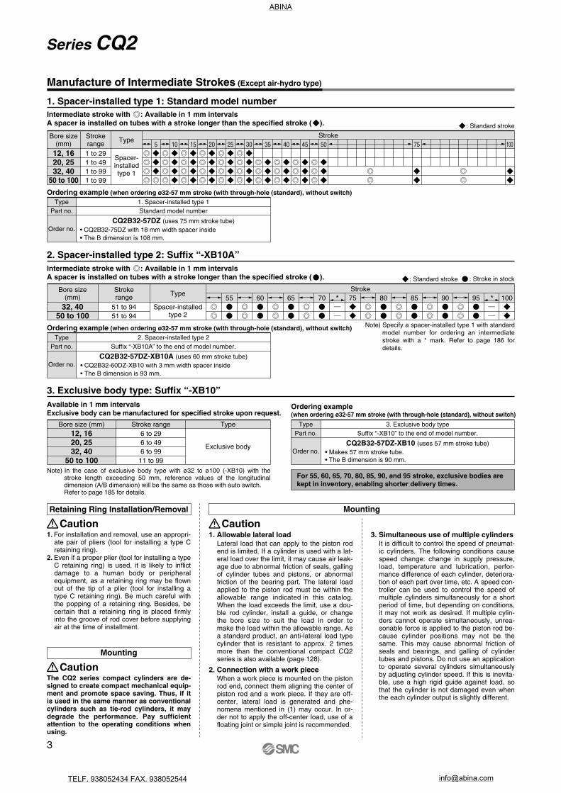
1. For installation and removal, use an appropri-ate pair of pliers (tool for installing a type C retaining ring).
2. Even if a proper plier (tool for installing a type C retaining ring) is used, it is likely to inflict damage to a human body or peripheral equipment, as a retaining ring may be flown out of the tip of a plier (tool for installing a type C retaining ring). Be much careful with the popping of a retaining ring. Besides, be certain that a retaining ring is placed firmly into the groove of rod cover before supplying air at the time of installment.
Retaining Ring Installation/Removal
Caution
The CQ2 series compact cylinders are de-signed to create compact mechanical equip-ment and promote space saving. Thus, if it is used in the same manner as conventional cylinders such as tie-rod cylinders, it may degrade the performance. Pay sufficientattention to the operating conditions when using.
Mounting
Caution
Mounting
Caution1. Allowable lateral load
Lateral load that can apply to the piston rod end is limited. If a cylinder is used with a lat-eral load over the limit, it may cause air leak-age due to abnormal friction of seals, galling of cylinder tubes and pistons, or abnormal friction of the bearing part. The lateral load applied to the piston rod must be within the allowable range indicated in this catalog. When the load exceeds the limit, use a dou-ble rod cylinder, install a guide, or change the bore size to suit the load in order to make the load within the allowable range. As a standard product, an anti-lateral load type cylinder that is resistant to approx. 2 times more than the conventional compact CQ2 series is also available (page 128).
2. Connection with a work pieceWhen a work piece is mounted on the piston rod end, connect them aligning the center of piston rod and a work piece. If they are off-center, lateral load is generated and phe-nomena mentioned in (1) may occur. In or-der not to apply the off-center load, use of a floating joint or simple joint is recommended.
3. Simultaneous use of multiple cylindersIt is difficult to control the speed of pneumat-ic cylinders. The following conditions cause speed change: change in supply pressure, load, temperature and lubrication, perfor-mance difference of each cylinder, deteriora-tion of each part over time, etc. A speed con-troller can be used to control the speed of multiple cylinders simultaneously for a short period of time, but depending on conditions, it may not work as desired. If multiple cylin-ders cannot operate simultaneously, unrea-sonable force is applied to the piston rod be-cause cylinder positions may not be the same. This may cause abnormal friction of seals and bearings, and galling of cylinder tubes and pistons. Do not use an application to operate several cylinders simultaneously by adjusting cylinder speed. If this is inevita-ble, use a high rigid guide against load, so that the cylinder is not damaged even when the each cylinder output is slightly different.
Manufacture of Intermediate Strokes (Except air-hydro type)
Bore size(mm)
Stroke
12, 1620, 2532, 40
50 to 100
Ordering example (when ordering ø32-57 mm stroke (with through-hole (standard), without switch)Type
Part no.
Order no.
1. Spacer-installed type 1Standard model number
CQ2B32-57DZ (uses 75 mm stroke tube)• CQ2B32-75DZ with 18 mm width spacer inside• The B dimension is 108 mm.
CQ2B32-57DZ-XB10A (uses 60 mm stroke tube)• CQ2B32-60DZ-XB10 with 3 mm width spacer inside• The B dimension is 93 mm.
CQ2B32-57DZ-XB10 (uses 57 mm stroke tube)• Makes 57 mm stroke tube.• The B dimension is 90 mm.
Ordering example (when ordering ø32-57 mm stroke (with through-hole (standard), without switch)Type
Part no.
Order no.
2. Spacer-installed type 2Suffix “-XB10A” to the end of model number.
Ordering example(when ordering ø32-57 mm stroke (with through-hole (standard), without switch)
TypePart no.
Order no.
3. Exclusive body typeSuffix “-XB10” to the end of model number.
Bore size(mm)
32, 4050 to 100
Strokerange
51 to 9451 to 94
55 60 65 70 75 80 85 90 95 100Type
Stroke
Spacer-installedtype 2
Strokerange1 to 291 to 491 to 991 to 99
5 10 15 20 25 30 35 40 45 50 75 100Type
Spacer-installedtype 1
Note) In the case of exclusive body type with ø32 to ø100 (-XB10) with the stroke length exceeding 50 mm, reference values of the longitudinal dimension (A/B dimension) will be the same as those with auto switch.Refer to page 185 for details.
Note) Specify a spacer-installed type 1 with standard model number for ordering an intermediate stroke with a * mark. Refer to page 186 for details.
For 55, 60, 65, 70, 80, 85, 90, and 95 stroke, exclusive bodies are kept in inventory, enabling shorter delivery times.
3. Exclusive body type: Suffix “-XB10”Available in 1 mm intervalsExclusive body can be manufactured for specified stroke upon request.
2. Spacer-installed type 2: Suffix “-XB10A”
1. Spacer-installed type 1: Standard model numberIntermediate stroke with : Available in 1 mm intervalsA spacer is installed on tubes with a stroke longer than the specified stroke ( ).
Bore size (mm)12, 1620, 2532, 40
50 to 100
Stroke range6 to 296 to 496 to 99
11 to 99
Type
Exclusive body
* *
: Standard stroke
: Standard stroke : Stroke in stock
Intermediate stroke with : Available in 1 mm intervalsA spacer is installed on tubes with a stroke longer than the specified stroke ( ).
3
Series CQ2
ABINA
TELF. 938052434 FAX. 938052544 [email protected]

12
16
20
25
32
40
50
63
80
100
Boresize(mm) 5
5
9
15
24
45
64
—
—
—
—
10
6
11
18
28
52
72
117
153
270
487
15
7
13
21
33
60
80
129
165
289
515
20
8
15
24
37
68
88
141
177
308
543
25
10
17
27
42
76
96
153
190
327
570
30
11
19
31
46
84
104
166
202
347
598
35
—
—
34
51
92
112
178
214
366
625
40
—
—
37
55
100
119
190
226
385
653
45
—
—
40
60
107
127
202
239
404
681
50
—
—
44
64
115
135
214
251
423
708
75
—
—
—
—
170
190
300
337
557
901
100
—
—
—
—
209
229
361
398
653
1038
(g)Mass of Cylinder Movable Parts/Without Built-in MagnetCylinder stroke (mm)
12
16
20
25
32
40
50
63
80
100
Boresize(mm) 5
8
16
28
44
78
109
—
—
—
—
10
9
18
31
48
86
117
187
254
433
741
15
10
20
34
53
93
125
199
266
453
768
20
11
22
37
57
101
133
211
278
472
796
25
12
24
40
62
109
140
223
290
491
823
30
13
26
44
66
117
148
236
303
510
851
35
—
—
47
71
125
156
248
315
530
879
40
—
—
50
75
133
164
260
327
549
906
45
—
—
53
80
140
172
272
339
568
934
50
—
—
56
84
148
180
285
352
587
962
75
—
—
—
—
187
219
346
413
683
1099
100
—
—
—
—
227
258
407
474
778
1236
(g)Mass of Cylinder Movable Parts/With Built-in Magnet
(g)Additional Mass of Cylinder Movable Parts
Cylinder stroke (mm)
Bore size (mm) 12
1.5
1
0
16
3
2
0
20
6
4
–2
25
12
8
–3
32
26
17
–3
40
27
17
–7
50
53
32
–9
63
53
32
–18
80
120
49
–31
100
175
116
–56
Bore size (mm) 12
0.022
0.043
16
0.038
0.075
20
0.055
0.110
25
0.09
0.18
32
0.15
0.29
40
0.26
0.52
50
0.46
0.91
63
0.77
1.54
80
1.36
2.71
100
2.27
4.54
(J)
Standard/Allowable kinetic energy: Ea
With rubber bumper/Allowable kinetic energy: Eb
W(Mounting orientation:
Horizontal)
If an allowable lateral load at rod end is exceeding the value in the graph, we recommend anti-lateral load type cylinder be used.
Cylinder stroke (mm)
100
504030
20
10
5.04.03.0
2.0
1.0
0.50 50 100
ø100
ø80
ø63
ø50ø40ø32
Allo
wab
le la
tera
l loa
d at
rod
end
W (
N)
Allo
wab
le la
tera
l loa
d at
rod
end
W (
N)
Cylinder stroke (mm)
ø100
ø80
ø63
ø50ø40ø32
200
100
504030
20
10
5.04.03.0
2.0
1.00 50 100
12
16
20
25
32
40
50
63
80
100
Bore size(mm)
Operatingdirection
INOUTIN
OUTIN
OUTIN
OUTIN
OUTIN
OUTIN
OUTIN
OUTIN
OUTIN
OUT
0.3253445607194
113147181241317377495589841935
1360151021402360
0.5425775
101118157189245302402528628825982
140015602270251035703930
0.75979
106141165220264344422563739880
11501370196021803170352050005500
Operating pressure (MPa)(N)
ø25
ø20ø16
ø12
ø25
ø20ø16
ø12
With Auto Switch
Allowable Kinetic Energy
Load Mass and Piston Speed
Kinetic energy E (J) =
m1: Mass of cylinder movable parts kgm2: Load mass kg V: Piston speed m/s
(m1+m2) V2
2
Rod end male thread
With rubber bumper
Male thread
Nut
Calculation: (Example) CDQ2B32-20DCMZ• Basic mass: CDQ2B32-20DZ• Additional mass: Rod end male thread
With rubber bumper
101 g43 g–3 g
141 g
Allowable Lateral Load at Rod End
Without Auto Switch
Theoretical Output
Sta
nd
ard
Lar
ge
Bo
reS
ize
Lo
ng
Str
oke
No
n-r
ota
tin
gR
od
Axi
al P
ipin
gA
nti
-lat
eral
Lo
adW
ith
En
d L
ock
Wat
erR
esis
tan
tA
uto
Sw
itch
Mad
e to
Ord
erW
ith
Au
toS
wit
ch
4
Series CQ2Compact Cylinder: StandardDouble Acting, Single Rod
ABINA
TELF. 938052434 FAX. 938052544 [email protected]

121620253240506380
100
Bore size(mm) 5 10 15 20 25 30 35 40 45 50 75 100
29426386125187————
3550751001452083394809161608
4159881151652303725189761688
476710112918425140555610361768
547611414420427343859410971849
608412715822429447163211571929
——
14017324431550467012172010
——
15218726333753770812772090
——
16520228335857074613382170
——
17821630338060378413982251
————
448552872111219172982
————
5476641043130822153391
(g)Weight (g)Additional WeightCylinder stroke (mm) Bore size (mm)
Both ends tapped
With boss on head endWith rubber bumperBuilt-in one-touch fittingsFoot (Including mounting bolts)Rod flange (Including mounting bolts)Head flange (Including mounting bolts)Double clevis (Including pin, retaining rings, bolts)
Rod endmale thread
Male threadNut
12 16 20 25 32 40 50 63 80 1002
1.51
0.70—55575432
232
1.30—67696539
6642
–2—
16413913388
61283–3—
186161152123
626175
–312142180165151
627177–712
154214198196
6533213–921243373348393
19533225
–1821
317559534554
451204945–31—
683105610171109
4517511696–56—
1052136513091887
Cylinder model C
6.5
5
7.5
9.5
D2530354045502530354045502530354045505560657030354045505560657075303540455055606570759095
100105110115120125130135
CQ-M3 x 25L x 30L x 35L x 40L x 45L x 50L
CQ-M3 x 25L x 30L x 35L x 40L x 45L x 50L
CQ-M5 x 25L x 30L x 35L x 40L x 45L x 50L x 55L x 60L x 65L x 70L
CQ-M5 x 30L x 35L x 40L x 45L x 50L x 55L x 60L x 65L x 70L x 75L
CQ-M5 x 30L x 35L x 40L x 45L x 50L x 55L x 60L x 65L x 70L x 75L x 90L x 95L
x 100L x 105L x 110L x 115L x 120L x 125L x 130L x 135L
Mounting bolt part no. Mounting bolt part no. Mounting bolt part no.CQ2B12-5D
-10D-15D-20D-25D-30D
CQ2B16-5D-10D-15D-20D-25D-30D
CQ2B20-5D-10D-15D-20D-25D-30D-35D-40D-45D-50D
CQ2B25-5D-10D-15D-20D-25D-30D-35D-40D-45D-50D
CQ2B32-5DZ-10DZ-15DZ-20DZ-25DZ-30DZ-35DZ-40DZ-45DZ-50DZ-55DZ-XB10-60DZ-XB10-65DZ-XB10-70DZ-XB10-75DZ-80DZ-XB10-85DZ-XB10-90DZ-XB10-95DZ-XB10-100DZ
Cylinder model C
14.5
15
15.5
D556065707580859095
11011512012513013514014515015565707580859095
100105120125130135140145150155160165
CQ-M10 x 55L x 60L x 65L x 70L x 75L x 80L x 85L x 90L x 95L
x 110L x 115L x 120L x 125L x 130L x 135L x 140L x 145L x 150L x 155L
CQ-M10 x 65L x 70L x 75L x 80L x 85L x 90L x 95L
x 100L x 105L x 120L x 125L x 130L x 135L x 140L x 145L x 150L x 155L x 160L x 165L
CQ2B80-10DZ-15DZ-20DZ-25DZ-30DZ-35DZ-40DZ-45DZ-50DZ-55DZ-XB10-60DZ-XB10-65DZ-XB10-70DZ-XB10-75DZ-80DZ-XB10-85DZ-XB10-90DZ-XB10-95DZ-XB10-100DZ
CQ2B100-10DZ-15DZ-20DZ-25DZ-30DZ-35DZ-40DZ-45DZ-50DZ-55DZ-XB10-60DZ-XB10-65DZ-XB10-70DZ-XB10-75DZ-80DZ-XB10-85DZ-XB10-90DZ-XB10-95DZ-XB10-100DZ
Cylinder model C
9
7.5
12.5
D3540455055606570758095
100105110115120125130135140455055606570758085
100105110115120125130135140145505560657075808590
105110115120125130135140145150
CQ-M5 x 35L x 40L x 45L x 50L x 55L x 60L x 65L x 70L x 75L x 80L x 95L
x 100L x 105L x 110L x 115L x 120L x 125L x 130L x 135L x 140L
CQ-M6 x 45L x 50L x 55L x 60L x 65L x 70L x 75L x 80L x 85L
x 100L x 105L x 110L x 115L x 120L x 125L x 130L x 135L x 140L x 145L
CQ-M8 x 50L x 55L x 60L x 65L x 70L x 75L x 80L x 85L x 90L
x 105L x 110L x 115L x 120L x 125L x 130L x 135L x 140L x 145L x 150L
CQ2B40-5DZ-10DZ-15DZ-20DZ-25DZ-30DZ-35DZ-40DZ-45DZ-50DZ-55DZ-XB10-60DZ-XB10-65DZ-XB10-70DZ-XB10-75DZ-80DZ-XB10-85DZ-XB10-90DZ-XB10-95DZ-XB10-100DZ
CQ2B50-10DZ-15DZ-20DZ-25DZ-30DZ-35DZ-40DZ-45DZ-50DZ-55DZ-XB10-60DZ-XB10-65DZ-XB10-70DZ-XB10-75DZ-80DZ-XB10-85DZ-XB10-90DZ-XB10-95DZ-XB10-100DZ
CQ2B63-10DZ-15DZ-20DZ-25DZ-30DZ-35DZ-40DZ-45DZ-50DZ-55DZ-XB10-60DZ-XB10-65DZ-XB10-70DZ-XB10-75DZ-80DZ-XB10-85DZ-XB10-90DZ-XB10-95DZ-XB10-100DZ
Mounting method: Mounting bolt for through-hole mounting of the CQ2B is available as an option. Refer to the following for ordering procedures. Order the actual number of bolts that will be used.
Example) CQ-M3x25L 4 pcs.Material: Chromium molybdenum steelSurface treatment: Nickel plated
Weight
Mounting Bolt for CQ2B/Without Auto Switch
Mounting bolt
Calculation: (Example) CQ2D32-20DCMZ• Basic weight: CQ2B32-20DZ• Additional weight: Both ends tapped
Rod end male threadWith rubber bumperDouble clevis
184 g6 g
43 g–3 g
151 g
381 g
5
Series CQ2
ABINA
TELF. 938052434 FAX. 938052544 [email protected]

121620253240506380100
CQ2B12-PS
CQ2B16-PS
CQ2B20-PS
CQ2B25-PS
CQ2B32-PS
CQ2B40-PS
CQ2B50-PS
CQ2B63-PS
CQ2B80-PS
CQ2B100-PS
20253240506380
100
CQ2BH20-PS
CQ2BH25-PS
CQ2BH32-PS
CQ2BH40-PS
CQ2BH50-PS
CQ2BH63-PS
CQ2BH80-PS
CQ2BH100-PS
Construction
Standard
Rod end male thread
With boss on head endWith rubber bumper
Built-in one-touch fittings
Cylinder tubePiston
Piston rod
Collar
Retaining ring
Bushing
Rod end nut
Bumper A
Bumper B
Centering location ring
One-touch fitting
Piston seal
Rod seal
Gasket
Component PartsNo.
1
2
3
4
5
6
7
8
Description Material
Aluminum alloy
Aluminum alloy
Stainless steel
Carbon steel
Aluminum alloy
Aluminum alloy casted
Carbon tool steel
Bearing alloy
Carbon steel
Urethane
Note
Hard anodized
Chromated
ø12 to ø25
ø32 to ø100, Hard chrome plated
ø12 to ø40, Anodized
ø50 to ø100, Chromated, Painted
Phosphate coated
For ø50 or more only
Nickel plated
No.
9
10
11
12
13
14
Description Material
Urethane
Aluminum alloy
—NBR
NBR
NBR
Note
ø20 to ø100, Hard anodized
ø32 to ø63
Replacement Parts/Seal Kit (Pneumatic type) Replacement Parts/Seal Kit (Air-hydro type)
∗ Seal kit includes !2, !3, !4. Order the seal kit, based on each bore size.∗ Since the seal kit does not include a grease pack, order it separately. Grease pack part no.: GR-S-010 (10 g)
∗ Seal kit includes !2, !3, !4. Order the seal kit, based on each bore size.∗ Since the seal kit does not include a grease pack, order it separately. Grease pack part no.: GR-S-010 (10 g)
Kits include items!2, !3, !4 fromthe table.
Kits include items!2, !3, !4 fromthe table.
Bore size (mm) Contents Bore size (mm) ContentsKit no. Kit no.
Sta
nd
ard
Lar
ge
Bo
reS
ize
Lo
ng
Str
oke
No
n-r
ota
tin
gR
od
Axi
al P
ipin
gA
nti
-lat
eral
Lo
adW
ith
En
d L
ock
Wat
erR
esis
tan
tA
uto
Sw
itch
Wit
h A
uto
Sw
itch
Mad
e to
Ord
er
6
Series CQ2Compact Cylinder: StandardDouble Acting, Single Rod
ABINA
TELF. 938052434 FAX. 938052544 [email protected]
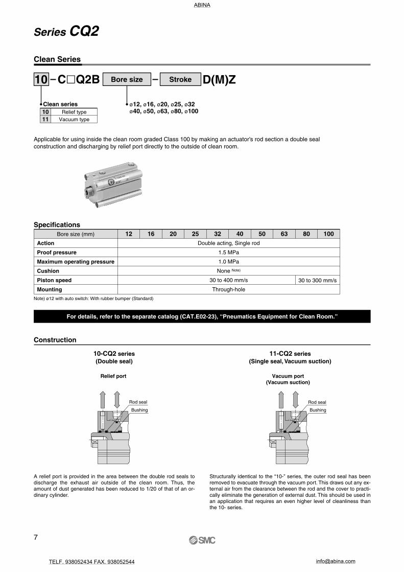
Clean Series
ø12, ø16, ø20, ø25, ø32ø40, ø50, ø63, ø80, ø100
Clean series1011
Relief typeVacuum type
Applicable for using inside the clean room graded Class 100 by making an actuator’s rod section a double seal construction and discharging by relief port directly to the outside of clean room.
10 Bore size StrokeCQ2B D(M)Z
SpecificationsBore size (mm)
Action
Proof pressure
Maximum operating pressure
Cushion
Piston speed
Mounting
Double acting, Single rod
1.5 MPa
1.0 MPa
None Note)
30 to 400 mm/s
Through-hole
Note) ø12 with auto switch: With rubber bumper (Standard)
30 to 300 mm/s
12 16 20 25 32 40 50 63 80 100
For details, refer to the separate catalog (CAT.E02-23), “Pneumatics Equipment for Clean Room.”
10-CQ2 series(Double seal)
11-CQ2 series(Single seal, Vacuum suction)
Construction
A relief port is provided in the area between the double rod seals to discharge the exhaust air outside of the clean room. Thus, the amount of dust generated has been reduced to 1/20 of that of an or-dinary cylinder.
Structurally identical to the “10-” series, the outer rod seal has been removed to evacuate through the vacuum port. This draws out any ex-ternal air from the clearance between the rod and the cover to practi-cally eliminate the generation of external dust. This should be used in an application that requires an even higher level of cleanliness than the 10- series.
Vacuum port(Vacuum suction)
Relief port
Bushing
Rod seal
Bushing
Rod seal
7
Series CQ2
ABINA
TELF. 938052434 FAX. 938052544 [email protected]

Ideal for use under the atmosphere having coolant for machine tools, etc. Compatible for the environment, where waterdrops are splashed around the food processing machinery and the car washers, etc.
SpecificationsBore size (mm)
Action
Cushion
Made to Order
Double acting, Single rod
None
Piston rod/Retaining ring/Rod end nut material: Stainless steel (-XC6)
20 25 32 40 50 63 80 100
CDQ2 Bore sizeMounting R Stroke Option -XC6D Z M9BAL
Water resistant 2-color indication
solid state auto switch
Made to Order
∗ The specifications other than above are the same as those of the standard.Some dimensions may vary from those of the standard. Refer to page 156 for details.
Piston rod/Retaining ring/Rod end nutmaterial: Stainless steel
Piston rod/Rod end nut/Cover holding boltmaterial: Stainless steel
Nil
A
Suffix
Note) -XC6A: ø20 to ø32 only
With auto switch(Built-in magnet)
Copper and Fluorine-free Series (For CRT Manufacturing Process)
For preventing the influence of copper ions or halogen ions during CRT manufacturing processes, copper and fluorine materials are not used in the component parts.
20 Bore size StrokeCQ2B D(C)(M)Z
ø12, ø16, ø20, ø25, ø32ø40, ø50, ø63, ø80, ø100
Copper and fluorine-free series
SpecificationsBore size (mm)
Action
Proof pressure
Maximum operating pressure
Cushion
Piston speed
Mounting
Double acting, Single rod
1.5 MPa
1.0 MPa
None/Rubber bumper
50 to 500 mm/s
Through-hole/Both ends tapped
12 16 20 25 32 40 50 63 80 100
Water resistant cylinderRV
NBR seals (Nitrile rubber)FKM seals (Fluororubber)
Refer to pages 156 to 168 for details.Water Resistant
Sta
nd
ard
Lar
ge
Bo
reS
ize
Lo
ng
Str
oke
No
n-r
ota
tin
gR
od
Axi
al P
ipin
gA
nti
-lat
eral
Lo
adW
ith
En
d L
ock
Wat
erR
esis
tan
tA
uto
Sw
itch
Mad
e to
Ord
erW
ith
Au
toS
wit
ch
8
Series CQ2Compact Cylinder: StandardDouble Acting, Single Rod
ABINA
TELF. 938052434 FAX. 938052544 [email protected]

Refer to the below pages for further information on auto switches.Auto switch proper mounting position and its mounting height
Minimum stroke for auto switch mounting
Operating range
Auto switch mounting brackets/Part no.
P.169 to 175
121620253240506380
100
Bore size(mm) 5 10 15 20 25 30 35 40 45 50 75 100
436494134182269————
497110614920229045562711621966
557911816422231248866512222047
618713118024133352170312822127
679514319526135555474113422208
7310215521028137658777914032288
——
16722630039862081714632368
——
17924132042065385515242449
——
19125634044168689315842529
——
20327235946371993116442610
————
459575891112919413018
————
5586871062132622373426
(g) (g)Additional WeightCylinder stroke (mm) Bore size (mm)
Both ends tapped
With boss on head endWith rubber bumperBuilt-in one-touch fittingsFoot (Including mounting bolts)Rod flange (Including mounting bolts)Head flange (Including mounting bolts)Double clevis (Including pin, retaining rings, bolts)
Rod end male thread
Male threadNut
12 16 20 25 32 40 50 63 80 1001
1.51
0.70—49545229
132
1.30—62676335
3642
–2—
14713112478
31283–3—
169153144114
626175
–312142180165151
627177–712
154214198196
6533213–921243373348393
19533225
–1821
317559534554
451204945–31—
683105610171109
4517511696–56—
1052136513091887
Replacement Parts/Seal Kit (Pneumatic type) Replacement Parts/Seal Kit (Air-hydro type)
121620253240506380
100
Bore size (mm) Kit no.CQ2B12-PSCQ2B16-PSCQ2B20-PSCQ2B25-PSCQ2B32-PSCQ2B40-PSCQ2B50-PSCQ2B63-PSCQ2B80-PSCQ2B100-PS
Contents
Kits include itemsi, o, !0 fromthe table.
Kits include itemsi, o, !0 fromthe table.
20253240506380
100
Bore size (mm) Kit no.CQ2BH20-PSCQ2BH25-PSCQ2BH32-PSCQ2BH40-PSCQ2BH50-PSCQ2BH63-PSCQ2BH80-PSCQ2BH100-PS
Contents
∗ Seal kit includes i, o, !0. Order the seal kit, based on each bore size. ∗ Since the seal kit does not include a grease pack, order it separately. Grease pack part no.: GR-S-010 (10 g)
Weight
Weight
Calculation: (Example) CDQ2D32-20DCMZ• Basic weight: CDQ2B32-20DZ• Additional weight: Both ends tapped
Rod end male threadWith rubber bumperDouble clevis
241 g6 g
43 g–3 g
151 g
438 g
Add each weight of auto switches when auto switches are mounted.
Construction
Component PartsNo.12
3
4
56789
10
Cylinder tubePiston
Piston rod
Collar
Retaining ringBushingMagnetPiston sealRod sealGasket
Description MaterialAluminum alloyAluminum alloyStainless steelCarbon steel
Aluminum alloyAluminum alloy castedCarbon tool steel
Bearing alloy—
NBRNBRNBR
NoteHard anodized
Chromatedø12 to ø25
ø32 to ø100, Hard chrome platedø12 to ø40, Anodized
ø50 to ø100, Chromated, PaintedPhosphate coated
For ø50 or more only
∗ Seal kit includes i, o, !0. Order the seal kit, based on each bore size. ∗ Since the seal kit does not include a grease pack, order it separately.
Grease pack part no.: GR-S-010 (10 g)
9
Standard: Double Acting, Single Rod
Series CDQ2With Auto Switch
ABINA
TELF. 938052434 FAX. 938052544 [email protected]

Mounting method: Mounting bolt for through-hole mounting of the CDQ2B is available as an option. Refer to the following for ordering procedures. Order the actual number of bolts that will be used.
Example) CQ-M3x35L 2 pcs.
Cylinder model C D3540455055654045505560654045505560657075808540455055606570758085404550556065707580859095
100105110115120125130135
CQ-M3 x 35L x 40L x 45L x 50L x 55L x 60L
CQ-M3 x 40L x 45L x 50L x 55L x 60L x 65L
CQ-M5 x 40L x 45L x 50L x 55L x 60L x 65L x 70L x 75L x 80L x 85L
CQ-M5 x 40L x 45L x 50L x 55L x 60L x 65L x 70L x 75L x 80L x 85L
CQ-M5 x 40L x 45L x 50L x 55L x 60L x 65L x 70L x 75L x 80L x 85L x 90L x 95L
x 100L x 105L x 110L x 115L x 120L x 125L x 130L x 135L
Mounting bolt part no. Mounting bolt part no. Mounting bolt part no.
CDQ2B12-5DZ-10DZ-15DZ-20DZ-25DZ-30DZ
CDQ2B16-5DZ-10DZ-15DZ-20DZ-25DZ-30DZ
CDQ2B20-5DZ-10DZ-15DZ-20DZ-25DZ-30DZ-35DZ-40DZ-45DZ-50DZ
CDQ2B25-5DZ-10DZ-15DZ-20DZ-25DZ-30DZ-35DZ-40DZ-45DZ-50DZ
CDQ2B32-5DZ-10DZ-15DZ-20DZ-25DZ-30DZ-35DZ-40DZ-45DZ-50DZ-55DZ-XB10-60DZ-XB10-65DZ-XB10-70DZ-XB10-75DZ-80DZ-XB10-85DZ-XB10-90DZ-XB10-95DZ-XB10-100DZ
Cylinder model C
14.5
D65707580859095
1001051101151201251301351401451501557580859095
100105110115120125130135140145150155160165
CQ-M10 x 65L x 70L x 75L x 80L x 85L x 90L x 95L
x 100L x 105L x 110L x 115L x 120L x 125L x 130L x 135L x 140L x 145L x 150L x 155L
CQ-M10 x 75L x 80L x 85L x 90L x 95L
x 100L x 105L x 110L x 115L x 120L x 125L x 130L x 135L x 140L x 145L x 150L x 155L x 160L x 165L
CDQ2B80-10DZ-15DZ-20DZ-25DZ-30DZ-35DZ-40DZ-45DZ-50DZ-55DZ-XB10-60DZ-XB10-65DZ-XB10-70DZ-XB10-75DZ-80DZ-XB10-85DZ-XB10-90DZ-XB10-95DZ-XB10-100DZ
CDQ2B100-10DZ-15DZ-20DZ-25DZ-30DZ-35DZ-40DZ-45DZ-50DZ-55DZ-XB10-60DZ-XB10-65DZ-XB10-70DZ-XB10-75DZ-80DZ-XB10-85DZ-XB10-90DZ-XB10-95DZ-XB10-100DZ
Cylinder model C D4550556065707580859095
100105110115120125130135140556065707580859095
1001051101151201251301351401456065707580859095
100105110115120125130135140145150
CQ-M5 x 45L x 50L x 55L x 60L x 65L x 70L x 75L x 80L x 85L x 90L x 95L
x 100L x 105L x 110L x 115L x 120L x 125L x 130L x 135L x 140L
CQ-M6 x 55L x 60L x 65L x 70L x 75L x 80L x 85L x 90L x 95L
x 100L x 105L x 110L x 115L x 120L x 125L x 130L x 135L x 140L x 145L
CQ-M8 x 60L x 65L x 70L x 75L x 80L x 85L x 90L x 95L
x 100L x 105L x 110L x 115L x 120L x 125L x 130L x 135L x 140L x 145L x 150L
CDQ2B40-5DZ-10DZ-15DZ-20DZ-25DZ-30DZ-35DZ-40DZ-45DZ-50DZ-55DZ-XB10-60DZ-XB10-65DZ-XB10-70DZ-XB10-75DZ-80DZ-XB10-85DZ-XB10-90DZ-XB10-95DZ-XB10-100DZ
CDQ2B50-10DZ-15DZ-20DZ-25DZ-30DZ-35DZ-40DZ-45DZ-50DZ-55DZ-XB10-60DZ-XB10-65DZ-XB10-70DZ-XB10-75DZ-80DZ-XB10-85DZ-XB10-90DZ-XB10-95DZ-XB10-100DZ
CDQ2B63-10DZ-15DZ-20DZ-25DZ-30DZ-35DZ-40DZ-45DZ-50DZ-55DZ-XB10-60DZ-XB10-65DZ-XB10-70DZ-XB10-75DZ-80DZ-XB10-85DZ-XB10-90DZ-XB10-95DZ-XB10-100DZ
8
5.5
10.5
9.5
15
15.5
9
7.5
12.5
Mounting bolt
Material: Chromium molybdenum steelSurface treatment: Nickel plated
Mounting Bolt for CDQ2B/With Auto Switch
Sta
nd
ard
Lar
ge
Bo
reS
ize
Lo
ng
Str
oke
No
n-r
ota
tin
gR
od
Axi
al P
ipin
gA
nti
-lat
eral
Lo
adW
ith
En
d L
ock
Wat
erR
esis
tan
tA
uto
Sw
itch
Wit
h A
uto
Sw
itch
Mad
e to
Ord
er
10
Series CQ2Compact Cylinder: StandardDouble Acting, Single Rod
ABINA
TELF. 938052434 FAX. 938052544 [email protected]

RR
G
øT
h9
øD
FQ
L
øI
EMZ
K
M
E
H1
C1
X
L1
MM
H thread effective depth C
8 x øO counterbore4 x øN through
O1 thread
B + Stroke
A + Stroke
(Port size)
2 x M5 x 0.8
Width across flat B1
L1
1415.518.522.5
Rod End Male ThreadBore size
(mm)
12162025
C1
9101215
B1
8101317
H1
4556
X
10.5121417.5
MM
M5 x 0.8M6 x 1.0M8 x 1.25M10 x 1.25
Standard (mm)
12162025
5 to 305 to 305 to 505 to 50
A
20.52224
27.5
B
1718.519.522.5
C
687
12
D
68
1012
E
25293640
F
55.55.55.5
H
M3 x 0.5M4 x 0.7M5 x 0.8M6 x 1.0
I
32384752
K
568
10
L
3.53.54.55
M
15.520
25.528
N
3.53.55.55.5
O
6.5 depth 3.56.5 depth 3.5
9 depth 79 depth 7
Q
7.589
11
Z
–101010
(mm)
Dimensions
ø12 to ø25/Without Auto Switch
Standard (Through-hole): CQ2B
Both ends tapped: CQ2A
R
77
1010
Both EndsTappedBore size
(mm)
(mm)
12162025
O1
M4 x 0.7M4 x 0.7M6 x 1.0M6 x 1.0
Rod end male thread
With boss on head end
Bore size(mm)
12162025
G
1.51.522
Th9
15201315
With Boss on Head End
0– 0.043 0– 0.052 0– 0.043 0– 0.043
Note 1) With boss on rod end: Option(Suffix “-XC36” to the end of model number.)
(mm)
Bore size(mm)
Stroke range(mm)
Note 2) The external dimensions with rubber bumper are same as those of the standard, as shown above.∗ For details about the rod end nut and accessory brackets, refer to page 19.Note 3) For calculation on the longitudinal dimension of intermediate strokes, refer to page 3.
11
Series CQ2
ABINA
TELF. 938052434 FAX. 938052544 [email protected]

CT
RR
CU
CWL
LH
LY
LZLX
L
LGLT
Y XYX
L1
FV
FXFZ
FTL
L1
L FT
L1
FV
FXFZ
L1
øCB
4 x øLD
LS + Stroke
B + Stroke
A + Stroke
Special cap bolt
2 x øFD
A + Stroke
B + Stroke
B + Stroke
CL + Stroke
A + Stroke
Cap bolt4 x N
Axis d9øCD hole H10
A + Stroke
B + Stroke 2 x øFD
CZ–0.1–0.3
CX+0.4+0.2
(mm)
(mm)
12162025
5 to 305 to 305 to 505 to 50
A
30.5
32
34
37.5
B
17
18.5
19.5
22.5
FD
4.5
4.5
6.6
6.6
FT
5.5
5.5
8
8
FV
25
30
39
42
FX
45
45
48
52
FZ
55
55
60
64
L
13.5
13.5
14.5
15
L1
24
25.5
28.5
32.5
12162025
5 to 305 to 305 to 505 to 50
A
2627.53235.5
L
3.53.54.55
L1
1415.518.522.5
(mm)
(mm)
12162025
5 to 305 to 305 to 505 to 50
A
35.3
36.8
41.2
44.7
B
17
18.5
19.5
22.5
L
13.5
13.5
14.5
15
L1
24
25.5
28.5
32.5
LD
4.5
4.5
6.6
6.6
LG
2.8
2.8
4
4
LH
17
19
24
26
LS
5
6.5
7.5
7.5
LT
2
2
3.2
3.2
LX
34
38
48
52
LY
29.5
33.5
42
46
LZ
44
48
62
66
X
8
8
9.2
10.7
Y
4.5
5
5.8
5.8
12162025
5 to 305 to 305 to 505 to 50
A
40.5435157.5
CB
12142024
B
1718.519.522.5
CD
558
10
CL
34.5374247.5
CT
4455
CU
7101214
CW
14151820
CX
56.58
10
CZ
10121620
L
3.53.54.55
L1
1415.518.522.5
N
M4 x 0.7M4 x 0.7M6 x 1.0M6 x 1.0
RR
669
10
Foot: CQ2L
Rod end male thread
Rod flange: CQ2F
Rod end male thread
Rod end male thread
Rod end male thread
Head flange: CQ2G
Double clevis: CQ2D
FootBore size(mm)
Stroke range(mm)
Foot bracket material: Carbon steelSurface treatment: Nickel plated
Rod Flange Bore size(mm)
Stroke range(mm)
Flange bracket material: Carbon steelSurface treatment: Nickel plated
Bore size(mm)
Stroke range(mm)
Head Flange
Flange bracket material: Carbon steelSurface treatment: Nickel plated
∗ The dimensions except A, L and L1 are the same as those of the rod flange.
Double ClevisBore size(mm)
Stroke range(mm)
Double clevis bracket material: Carbon steelSurface treatment: Nickel plated
∗ For details about the rod end nut and accessory brackets, refer to page 19.∗ Double clevis pin and retaining rings are included.
Sta
nd
ard
Lar
ge
Bo
reS
ize
Lo
ng
Str
oke
No
n-r
ota
tin
gR
od
Axi
al P
ipin
gA
nti
-lat
eral
Lo
adW
ith
En
d L
ock
Wat
erR
esis
tan
tA
uto
Sw
itch
Mad
e to
Ord
erW
ith
Au
toS
wit
ch
12
Series CQ2Compact Cylinder: StandardDouble Acting, Single Rod
ABINA
TELF. 938052434 FAX. 938052544 [email protected]

(mm)
12162025
5 to 305 to 305 to 505 to 50
A
31.53436
37.5
B
2830.531.532.5
C
687
12
D
68
1012
E
33374752
EA
—13.213.613.6
EB
—6.66.86.8
F
6.55.55.55.5
H
M3 x 0.5M4 x 0.7M5 x 0.8M6 x 1.0
K
568
10
L
3.53.54.55
M
22283640
N
3.53.55.55.5
O
6.5 depth 3.56.5 depth 3.5
9 depth 79 depth 7
Q
1110
10.511
S
27.529.535.540.5
U
14151821
V
25293640
S
U
EBEA
H1
C1
XL1
G
øT
h9
RR
øD
FQLV
E
M
K
MM
ø12
ø16 to ø25
K
M
E
8
S
Uø12 to ø25/With Auto Switch
Dimensions
R
77
1010
Both EndsTappedBore size
(mm)
12162025
O1
M4 x 0.7M4 x 0.7M6 x 1.0M6 x 1.0
(mm)
With Boss on Head End (mm)
Bore size(mm)
12162025
G
1.51.522
Th9
15 0–0.043
20 0–0.052
13 0–0.043
15 0–0.043
Note 1) With boss on rod end: Option (Suffix “-XC36” to the end of model number.)
Rod End Male ThreadBore size(mm)
12162025
C1
9101215
H1
4556
B1
8101317
L1
1415.518.522.5
MM
M5 x 0.8M6 x 1.0
M8 x 1.25M10 x 1.25
X
10.5121417.5
(mm)
Standard (Through-hole): CDQ2B
Both ends tapped: CDQ2A
O1 thread
With boss on head end
B + Stroke
A + Stroke
Auto switch
Minimum lead wire bending radius 10
2 x M5 x 0.8(Port size)
H thread effective depth C
2 x øN through4 x øO counterbore
Rod end male thread
Width across flat B1
2 x øN through4 x øO counterbore
H thread effective depth C
V
Note 2) The external dimensions with rubber bumper are same as those of the standard, as shown above.∗ For details about the rod end nut and accessory brackets, refer to page 19.Note 3) For calculation on the longitudinal dimension of intermediate strokes, refer to page 3.
Standard For auto switch proper mounting position and its mounting height, refer to pages 169 to 175.
Bore size(mm)
Stroke range(mm)
13
Series CQ2
ABINA
TELF. 938052434 FAX. 938052544 [email protected]

øCB
LXLZ
LY
LH
X Y XYLT LG
L
L1
FZFX
FV
L
FT
L1
LFZFX
FV
FT
L1
CU
CT
L CW RR
L1
4 x øLD
Special cap bolt
A + Stroke
B + Stroke
LS + Stroke
2 x øFD
2 x øFD
A + Stroke
B + Stroke
B + Stroke
A + Stroke
2 x NCap bolt
øCD hole H10Axis d9
CZCX
B + Stroke
A + StrokeCL + Stroke
+0.4+0.2
–0.1–0.3
(mm)
(mm)
12162025
5 to 305 to 305 to 505 to 50
A
41.5
44
46
47.5
B
28
30.5
31.5
32.5
FD
4.5
4.5
6.6
6.6
FT
5.5
5.5
8
8
FV
25
30
39
42
FX
45
45
48
52
FZ
55
55
60
64
L
13.5
13.5
14.5
15
L1
24
25.5
28.5
32.5
12162025
5 to 305 to 305 to 505 to 50
A
3739.54445.5
L
3.53.54.55
L1
1415.518.522.5
(mm)
12162025
5 to 305 to 305 to 505 to 50
A
46.3
48.8
53.2
54.7
B
28
30.5
31.5
32.5
L
13.5
13.5
14.5
15
L1
24
25.5
28.5
32.5
LD
4.5
4.5
6.6
6.6
LG
2.8
2.8
4
4
LH
17
19
24
26
LS
16
18.5
19.5
17.5
LT
2
2
3.2
3.2
LX
34
38
48
52
LY
29.5
33.5
42
46
LZ
44
48
62
66
X
8
8
9.2
10.7
Y
4.5
5
5.8
5.8
12162025
5 to 305 to 305 to 505 to 50
A
51.5556367.5
CB
12142024
B
2830.531.532.5
CD
558
10
CL
45.5495457.5
CT
4455
CU
7101214
CW
14151820
CX
56.58
10
CZ
10121620
L
3.53.54.55
L1
1415.518.522.5
N
M4 x 0.7M4 x 0.7M6 x 1.0M6 x 1.0
RR
669
10
Foot: CDQ2L
Rod flange: CDQ2F
Rod end male thread
Head flange: CDQ2G
Rod end male thread
Rod end male thread
Double clevis: CDQ2D
Rod end male thread
FootBore size(mm)
Stroke range(mm)
Foot bracket material: Carbon steelSurface treatment: Nickel plated
Rod FlangeBore size(mm)
Stroke range(mm)
Flange bracket material: Carbon steelSurface treatment: Nickel plated
Bore size(mm)
Stroke range(mm)
Head Flange (mm)
Flange bracket material: Carbon steelSurface treatment: Nickel plated
∗ The dimensions except A, L and L1 are the same as those of the rod flange.
∗ For details about the rod end nut and accessory brackets, refer to page 19.∗ Double clevis pin and retaining rings are included.
Double ClevisBore size(mm)
Stroke range(mm)
Double clevis bracket material: Carbon steelSurface treatment: Nickel plated
Sta
nd
ard
Lar
ge
Bo
reS
ize
Lo
ng
Str
oke
No
n-r
ota
tin
gR
od
Axi
al P
ipin
gA
nti
-lat
eral
Lo
adW
ith
En
d L
ock
Wat
erR
esis
tan
tA
uto
Sw
itch
Mad
e to
Ord
erW
ith
Au
toS
wit
ch
14
Series CQ2Compact Cylinder: StandardDouble Acting, Single Rod
ABINA
TELF. 938052434 FAX. 938052544 [email protected]

Z
H1
RR
M E
JW
øD
FQ
L
EMK
W1
V
øZ
1
2
øT
h9
C1
XL1
MM
B + Stroke
A + Stroke
Minimum lead wire bending radius 10 Auto switch
2 x P (Rc, NPT, G)(Port size)
O1 thread
4 x øN through8 x øO counterbore
H thread effective depth C
Width across flat B1
2 x P1
(Piping tube O.D.)
Standard For auto switch proper mounting position and its mounting height, refer to pages 169 to 175. (mm)
32
40
50
32
40
50
510 to 5075, 1005 to 5075, 10010 to 5075, 100
A
30
4036.546.538.548.5
B
23
3329.539.530.540.5
F5.5
7.5
8
10.5
Q11.5
10.5
11
10.5
A
40
46.5
48.5
B
33
39.5
40.5
C
13
13
15
Q
10.5
11
10.5
F
7.5
8
10.5
D
16
16
20
E
45
52
64
J
4.5
5
7
H
M8 x 1.25
M8 x 1.25
M10 x 1.5
P
1/8
1/8
1/4
PM5 x 0.8
1/8
1/8
1/4
K
14
14
17
L
7
7
8
M
34
40
50
N
5.5
5.5
6.6
W
49.5
57
71
Z
14
15
19
Dimensions(In the case of without auto switches, the A, B, F, P and Q dimensions will be only changed. Refer to the dimension table.)ø32 to ø50/With Auto Switch
R
101014
Both EndsTappedBore size
(mm)
324050
O1
M6 x 1.0M6 x 1.0M8 x 1.25
(mm)
(mm)
With Boss on Head EndBore size
(mm)
324050
Th9
21 0–0.052
28 0–0.052
35 0–0.062
Note 1) With boss on rod end: Option (Suffix “-XC36” to the end of model number.)
Rod End Male ThreadBore size(mm)
324050
C1
20.5
20.5
26
H1
8
8
11
B1
22
22
27
L1
28.5
28.5
33.5
MM
M14 x 1.5
M14 x 1.5
M18 x 1.5
X
23.5
23.5
28.5
Bore size(mm)
324050
Z1
13
13
16
P1
6
6
8
V
36.5
40.5
50
W1
59
66
82
Built-in One-touch Fittings (mm)
(mm)
Bore size(mm)
Bore size(mm)
Stroke range(mm)
O
9 depth 7
9 depth 7
11 depth 8
Without auto switch With auto switch
Note 2) The external dimensions with rubber bumper are same as those of the standard, as shown above.∗ For details about the rod end nut and accessory brackets, refer to page 19. Note 3) For calculation on the longitudinal dimension of intermediate strokes, refer to page 3. The spacer-
installed type (Standard, -XB10A) and the exclusive body type (-XB10) are available.
Standard (Through-hole): CQ2B/CDQ2B
Both ends tapped: CQ2A/CDQ2A
Built-in one-touch fittings: ø32 to ø50
Rod end male thread
With boss on head end
15
Series CQ2
ABINA
TELF. 938052434 FAX. 938052544 [email protected]

L1
L1
L1
FTL
M FV
FXFZ
CT
CURRCWL
FTL
MFV
FXFZ
LZLX
LY
LH
L
X Y XYL
T LG
L1
4 x øLD
Special cap bolt
B + Stroke
A + Stroke
LS + Stroke
B + Stroke
A + Stroke
4 x øFD
CX
CZB + Stroke
CL + Stroke
A + Stroke
A + Stroke
B + Stroke
4 x NCap bolt
øCD hole H10Axis d9
4 x øFD
–0.1–0.3
+0.4+0.2
(mm)
32
40
50
5 to 5075, 1005 to 5075, 10010 to 5075, 100
A47.257.253.763.756.766.7
B233329.539.530.540.5
LS7
1713.523.57.517.5
A
57.2
63.7
66.7
B33
39.5
40.5
LS17
23.5
17.5
L
17
17
18
L1
38.5
38.5
43.5
LD
6.6
6.6
9
LG
4
4
5
LH
30
33
39
LT
3.2
3.2
3.2
LX
57
64
79
LY
57
64
78
(mm)
32
40
50
5 to 5075, 1005 to 5075, 10010 to 5075, 100
A405046.556.548.558.5
B233329.539.530.540.5
A
50
56.5
58.5
B
33
39.5
40.5
FD
5.5
5.5
6.6
FT
8
8
9
FV
48
54
67
FX
56
62
76
FZ
65
72
89
L
17
17
18
L1
38.5
38.5
43.5
M
34
40
50
(mm)
32
40
50
5 to 5075, 1005 to 5075, 10010 to 5075, 100
48
54.5
57.5
3848
44.554.547.557.5
L
7
7
8
L1
28.5
28.5
33.5
(mm)
32
40
50
5 to 5075, 1005 to 5075, 10010 to 5075, 100
A607068.578.580.590.5
B233329.539.530.540.5
CL506058.568.566.576.5
A70
78.5
90.5
B33
39.5
40.5
CL60
68.5
76.5
CD
10
10
14
CT
5
6
7
CU
14
14
20
CW
20
22
28
CX
18
18
22
CZ
36
36
44
L
7
7
8
L1
28.5
28.5
33.5
32
40
50
LZ
71
78
95
X
11.2
11.2
14.7
Y
5.8
7
8
32
40
50
N
M6 x 1.0
M6 x 1.0
M8 x 1.25
RR
10
10
14
Foot: CQ2L/CDQ2L
Rod end male thread
Rod flange: CQ2F/CDQ2F
Rod end male thread
Head flange: CQ2G/CDQ2G
Double clevis: CQ2D/CDQ2D
Rod end male thread
Rod end male thread
FootBore size(mm)
Without auto switch With auto switchStroke range(mm)
Bore size(mm)
Foot bracket material: Carbon steelSurface treatment: Nickel plated
Rod FlangeBore size(mm)
Stroke range(mm)
Withoutauto switch
Withauto switch
Flange bracket material: Carbon steelSurface treatment: Nickel plated
Stroke range(mm)
Head FlangeBore size(mm)
Withauto switch
A
Withoutauto switch
A
Flange bracket material: Carbon steelSurface treatment: Nickel plated
∗ The dimensions except A, L and L1 are the same as those of the rod flange.
Stroke range(mm)
Double ClevisBore size(mm)
Without auto switch With auto switch
Double clevis bracket material: Cast ironSurface treatment: Painted
∗ For details about the rod end nut and accessory brackets, refer to page 19.∗ Double clevis pin and retaining rings are included.
Bore size(mm)
Sta
nd
ard
Lar
ge
Bo
reS
ize
Lo
ng
Str
oke
No
n-r
ota
tin
gR
od
Axi
al P
ipin
gA
nti
-lat
eral
Lo
adW
ith
En
d L
ock
Wat
erR
esis
tan
tA
uto
Sw
itch
Mad
e to
Ord
erW
ith
Au
toS
wit
ch
16
Series CQ2Compact Cylinder: StandardDouble Acting, Single Rod
ABINA
TELF. 938052434 FAX. 938052544 [email protected]

H1
W1
V
øZ
1
C1
XL1
øT
h9
2
J
øD
FQ
L
Z M E
KMEW
MM
RR
B + Stroke
A + Stroke
Minimum lead wire bending radius 10 Auto switch
2 x P (Rc, NPT, G)(Port size)
H thread effectivedepth C 4 x øN through
8 x øO counterbore
O1 thread
2 x P1
(Piping tube O.D.)
Width across flat B1 6380
100
C1
26
32.5
32.5
B1
27
32
41
L1
33.5
43.5
43.5
H1
11
13
16
MM
M18 x 1.5
M22 x 1.5
M26 x 1.5
X
28.5
35.5
35.5
(mm)
(mm)
63
80
100
10 to 5075, 10010 to 5075, 10010 to 5075, 100
A4454
53.563.56575
B3646
43.553.55363
A
54
63.5
75
B
46
53.5
63
C
15
21
27
D
20
25
30
E
77
98
117
F
10.5
12.5
13
H
M10 x 1.5
M16 x 2.0
M20 x 2.5
J
7
6
6.5
K
17
22
27
L
8
10
12
M
60
77
94
N
9
11
11
Z
19
25
25
O
14 depth 10.5
17.5 depth 13.5
17.5 depth 13.5
P
1/4
3/8
3/8
Q
15
16
23
W
84
104
123.5
Dimensions(In the case of without auto switches, the A, B dimensions will be only changed. Refer to the dimension table.)ø63 to ø100/With Auto Switch
R
182222
Both EndsTappedBore size
(mm)
6380
100
O1
M10 x 1.5M12 x 1.75M12 x 1.75
(mm)
(mm)With Boss on Head EndBore size
(mm)
6380
100
Th9
35 0–0.062
43 0–0.062
59 0–0.074
Note 1) With boss on rod end: Option (Suffix “-XC36” to the end of model number.)
Rod End Male ThreadBore size(mm)
(mm)
Bore size(mm)
63
Z1
16
P1
8
V
56.5
W1
95
Built-in One-touch Fittings
Note 2) The external dimensions with rubber bumper are same as those of the standard, as shown above.∗ For details about the rod end nut and accessory brackets, refer to page 19.Note 3) For calculation on the longitudinal dimension of intermediate strokes, refer to page 3.
Bore size(mm)
Stroke range(mm)
Withoutauto switch
Withauto switch
Standard For auto switch proper mounting position and its mounting height, refer to pages 169 to 175.
Standard (Through-hole):CQ2B/CDQ2B
Both ends tapped: CQ2A/CDQ2A
With boss on head end
Built-in one-touch fittings: ø63
Rod end male thread
17
Series CQ2
ABINA
TELF. 938052434 FAX. 938052544 [email protected]

CT
CURRCWL
L1
FTL
L1
FXFZ
MFV
FT
LFXFZ
M FV
L1
LZLX
LY
LH
X Y XY
L
L1
LGLT4 x øLD
Special cap bolt
A + Stroke
LS + Stroke
B + Stroke
B + Stroke
A + Stroke
4 x øFD
B + Stroke
A + Stroke
4 x øFD
CXCZB + Stroke
CL + Stroke
A + Stroke
øCD hole H10Axis d9
4 x NCap bolt
+0.4+0.2
–0.1–0.3
(mm)
A62.272.275858898
B3646
43.553.55363
LS1020
13.523.51929
A72.2
85
98
LS20
23.5
29
B46
53.5
63
L
18
20
22
L1
43.5
53.5
53.5
LD
11
13
13
LG
5
7
7
LH
46
59
71
LT
3.2
4.5
6
(mm)
FD
9
11
11
FT
9
11
11
FV
80
99
117
FX
92
116
136
FZ
108
134
154
L
18
20
22
L1
43.5
53.5
53.5
M
60
77
94
(mm)
L
8
10
12
L1
33.5
43.5
43.5
(mm)
CD
14
18
22
CT
8
10
13
CU
20
27
31
CW
30
38
45
CX
22
28
32
LY
91.5
114
136
LX
95
118
137
LZ
113
140
162
X
16.2
19.5
23
Y
9
11
12.5
A5464
63.573.57585
B3646
43.553.55363
A64
73.5
85
B46
53.5
63
A5363
64.574.57686
A63
74.5
86
A8898
109.5119.5132142
B3646
43.553.55363
CL748491.5
101.5110120
A98
119.5
142
CL84
101.5
120
B46
53.5
63
L1
33.5
43.5
43.5
N
M10 x 1.5
M12 x 1.75
M12 x 1.75
RR
14
18
22
CZ
44
56
64
L
8
10
12
Foot: CQ2L/CDQ2L
Rod end male thread
Rod flange: CQ2F/CDQ2F
Rod end male thread
Head flange: CQ2G/CDQ2G
Rod end male thread
Double clevis: CQ2D/CDQ2D
Rod end male thread
FootBore size(mm)
63
80
100
Stroke range(mm)
10 to 5075, 10010 to 5075, 10010 to 5075, 100
With auto switch
Bore size(mm)
63
80
100
Stroke range(mm)
10 to 5075, 10010 to 5075, 10010 to 5075, 100
Foot bracket material: Carbon steelSurface treatment: Nickel plated
Without auto switch
Rod FlangeBore size(mm)
63
80
100
Stroke range(mm)
10 to 5075, 10010 to 5075, 10010 to 5075, 100
With auto switch
Flange bracket material: Carbon steelSurface treatment: Nickel plated
Without auto switch
Head FlangeBore size(mm)
63
80
100
Stroke range(mm)
10 to 5075, 10010 to 5075, 10010 to 5075, 100
∗ The dimensions except A, L and L1 are the same as those of the rod flange.
Without auto switch With auto switch
Flange bracket material: Carbon steel Surface treatment: Nickel plated
Double ClevisBore size(mm)
63
80
100
Stroke range(mm)
10 to 5075, 10010 to 5075, 10010 to 5075, 100
Double clevis bracket material:Cast iron
Surface treatment: Painted
Without auto switch With auto switch
∗ For details about the rod end nut and accessory brackets, refer to page 19.∗ Double clevis pin and retaining rings are included.
Bore size(mm)
63
80
100
Stroke range(mm)
10 to 5075, 10010 to 5075, 10010 to 5075, 100
Sta
nd
ard
Lar
ge
Bo
reS
ize
Lo
ng
Str
oke
No
n-r
ota
tin
gR
od
Axi
al P
ipin
gA
nti
-lat
eral
Lo
adW
ith
En
d L
ock
Wat
erR
esis
tan
tA
uto
Sw
itch
Mad
e to
Ord
erW
ith
Au
toS
wit
ch
18
Series CQ2Compact Cylinder: StandardDouble Acting, Single Rod
ABINA
TELF. 938052434 FAX. 938052544 [email protected]

ø ø
I-G012I-Z015AI-G02I-G03I-G04I-G05I-G08I-G10
(mm)
A
21.532344142567179
A1
68
8.510.514182121
L1
1625253030405055
MM
M5 x 0.8M6 x 1M8 x 1.25M10 x 1.25M14 x 1.5M18 x 1.5M22 x 1.5M26 x 1.5
RR1
6.38.110.312.812162124
U1
714
11.51414202731
NDH10 NX
12162025
32, 4050, 63
80100
558
1010141822
56.48
1018222832
–0.2–0.4
–0.1–0.3
–0.2–0.4
–0.2–0.4
–0.3–0.5
–0.3–0.5
–0.3–0.5
–0.3–0.5
Y-G012Y-Z015AY-G02Y-G03Y-G04Y-G05Y-G08Y-G10
(mm)
A
21.528344142567179
A1
6118.510.516202324
L1
1621253030405055
NZ
1012162036445664
L
14.616.62125.641.650.66472
MM
M5 x 0.8M6 x 1
M8 x 1.25M10 x 1.25M14 x 1.5M18 x 1.5M22 x 1.5M26 x 1.5
RR1
6.38.110.312.812162124
U1
71011.51414202731
NDH10 NX
12162025
32, 4050, 63
80100
5581010141822
56.58
1018222832
IY-G012IY-J015IY-G02IY-G03IY-G04IY-G05IY-G08IY-G10
∗ Knuckle pin and retaining rings are included.
IY-G012IY-J015IY-G02IY-G03IY-G04IY-G05IY-G08IY-G10
L
14.616.62125.641.650.66472
d
4.84.87.69.69.613.41721
l
10.212.216.220.236.244.256.264.2
m
1.51.51.51.551.552.052.552.55
t
0.70.70.91.151.151.151.351.35
12162025
32, 4050, 63
80100
NTJ-015ANT-015ANT-02NT-03NT-04NT-05NT-08NT-10
12162025
32, 4050, 63
80100
d
M5 x 0.8M6 x 1
M8 x 1.25M10 x 1.25M14 x 1.5M18 x 1.5M22 x 1.5M26 x 1.5
H
45568
111316
B
810131722273241
C
9.211.515.019.625.431.237.047.3
558
1010141822
–0.030–0.060
–0.030–0.060
–0.040–0.076
–0.040–0.076
–0.040–0.076
–0.050–0.093
–0.050–0.093
–0.065–0.117
Dd9
(mm)
ø ø
l
Accessory Brackets
I-G012, I-Z015AI-G02, I-G03
I-G04, I-G05I-G08, I-G10
Y-G012, Y-Z015AY-G02, Y-G03
Y-G04, Y-G05Y-G08, Y-G10
Single Knuckle Joint Double Knuckle Joint
Material: Carbon steelSurface treatment: Nickel plated
Material: Cast ironSurface treatment: Nickel plated
Material: Carbon steelSurface treatment: Nickel plated
Material: Cast ironSurface treatment: Nickel plated
Axis d9øND hole H10
Axis d9øND hole H10
Part no.Applicablebore size
(mm)E1
10121620ø22ø28ø38ø44
+0.0480
+0.0480
+0.0580
+0.0580
+0.0580
+0.0700
+0.0700
+0.0840
Part no. E1
10121620ø22ø28ø38ø44
Applicablebore size
(mm)+0.048
0+0.4+0.2
+0.2+0
+0.4+0.2
+0.4+0.2
+0.5+0.3
+0.5+0.3
+0.5+0.3
+0.5+0.3
+0.0480
+0.0580
+0.0580
+0.0580
+0.0700
+0.0700
+0.0840
Applicablepin
part no.
Knuckle Pin (Common with double clevis pin) Rod End Nut
∗ Type C retaining rings for axis are included.
Part no.Applicablebore size
(mm)Applicable
retaining ringType C5 for axisType C5 for axisType C8 for axis
Type C10 for axisType C10 for axisType C14 for axisType C18 for axisType C22 for axis
Material: Carbon steel(mm)
Part no. Applicablebore size (mm)
Material: Carbon steelSurface treatment: Nickel plated
19
Series CQ2
ABINA
TELF. 938052434 FAX. 938052544 [email protected]

YA 03
Allowable Eccentricity (mm)
32 40 50 63 80 100±1 ±1.5 ±2
0.5
Joint/Mounting Bracket (Type A/B)/Part No.
32, 4050, 63
80100
YU-03
YU-05
YU-08
YU-10
Type A mounting bracket
YA-03
YA-05
YA-08
YA-10
Type B mounting bracket
YB-03
YB-05
YB-08
YB-10
UA C d1 d2 H K L UT Weight(g)
25
40
90
160
YU-03YU-05YU-08YU-10
17
17
22
26
11
13
20
26
15.8
19.8
24.8
29.8
14
18
23
28
M8 x 1.25
M10 x 1.5
M16 x 2
M20 x 2.5
8
10
13
14
7
7
9
11
6
6
8
10
YA-03YA-05YA-08YA-10
32, 4050, 63
80100
B
18
20
26
31
D
6.8
9
11
14
E
16
20
25
30
F
6
8
10
12
M
42
50
62
76
T1
6.5
6.5
8.5
10.5
T2
10
12
16
18
YA-03YA-05YA-08YA-10
32, 4050, 63
80100
U
6
8
10
12
V
18
22
28
36
W
56
67
83
100
55
100
195
340
32, 4050, 63
80100
H
CUALUT
ød
2
ød
1
M W
E
T1U
VT2
FB
T1
T2V
B
RS
M W
J
E
03050810
For ø32, ø40For ø50, ø63
For ø80For ø100
YAYBYU
Type A mounting bracketType B mounting bracket
Joint
Part no.
YB-03YB-05YB-08YB-10
Bore size(mm)
32, 4050, 63
80100
B
12
12
16
19
D
7
9
11
14
E
25
32
38
50
J
9
11
13
17
M
34
42
52
62
øO
11.5 depth 7.5
14.5 depth 8.5
18 depth 12
21 depth 14
Part no.
YB-03YB-05YB-08YB-10
Bore size(mm)
32, 4050, 63
80100
T1
6.5
6.5
8.5
10.5
T2
10
12
16
18
V
18
22
28
36
W
50
60
75
90
RS
9
11
14
18
Weight (g)
80
120
230
455
Simple Joint (CQ2): ø32 to ø100
Joint/Mounting Bracket (Type A/B)/Part No.
Mounting bracket
Applicable air cylinderbore size
Eccentricity tolerance
Backlash
Bore size (mm)
<Ordering>• Joints are not included with type A or B mounting brackets.
Order them separately.(Example)Bore size ø40 Part no.• Type A mounting bracket ·········· YA-03• Joint ··········································· YU-03
Bore size(mm)
JointApplicable mounting bracket
K (
Wid
th
acro
ss fl
at)
(With locking)
Material: Chromium molybdenum steel (Nickel plated)(mm)
Part no.Applicablebore size
(mm)
Material: Chromium molybdenum steel (Nickel plated)(mm)
Type A Mounting Bracket
2 x øD
Joint
Part no. Bore size(mm)
Part no. Bore size(mm) Weight (g)
Material: Stainless steel(mm)
Type B Mounting Bracket
2 x øO counterbore2 x øD through
Joint
Sta
nd
ard
Lar
ge
Bo
reS
ize
Lo
ng
Str
oke
No
n-r
ota
tin
gR
od
Axi
al P
ipin
gA
nti
-lat
eral
Lo
adW
ith
En
d L
ock
Wat
erR
esis
tan
tA
uto
Sw
itch
Mad
e to
Ord
erW
ith
Au
toS
wit
ch
20
Series CQ2Compact Cylinder: StandardDouble Acting, Single Rod
ABINA
TELF. 938052434 FAX. 938052544 [email protected]


∗ ∗ Water resistant type auto switches can be mounted on the above models, but in such case SMC cannot guarantee water resistance. Consult with SMC regarding water resistant types with the above model numbers.
24 V
5 V,12 V12 V5 V,12 V12 V5 V,12 V12 V—
M9NVM9PVM9BV
M9NWVM9PWVM9BWVM9NAV
∗∗
M9PAV ∗∗
M9BAV ∗∗
—
—
M9NM9PM9B
M9NWM9PWM9BW
M9NA ∗∗
M9PA ∗∗
M9BA ∗∗
P3DW
24 V
— —
100 V100 V or less
5 V
12 V5 V,12 V
A96V
A93VA90V
A96
A93A90
30
30
32
32
CQ2W B
B M9BWCDQ2W
Cylinder stroke (mm)Refer to the next page for standard strokes.
D
D
3020CQ2W B D
Bore size121620253240506380
100
12 mm16 mm20 mm25 mm32 mm40 mm50 mm63 mm80 mm
100 mm
Built-in Magnet Cylinder ModelIf a built-in magnet cylinder without an auto switch is required, there is no need to enter the symbol for the auto switch.(Example) CDQ2WL32-25DZ
Built-in one-touch fittings Note 2 )
M threadRc
NPTG
ø12 to ø25
ø32 to ø100
Port thread type
Nil
TNTFF
Z
Z
Compact Cylinder: StandardDouble Acting, Double Rod
Series CQ2Wø12, ø16, ø20, ø25, ø32, ø40, ø50, ø63, ø80, ø100
How to Order
With auto switch
Without auto switchø12 to ø25
Without auto switchø32 to ø100
With auto switch(Built-in magnet)
Through-hole (Standard)Both ends tapped
BA
FootFlange
LF
Mounting
∗ Mounting brackets are shipped together, (but not assembled).∗ Cylinder mounting bolts are not included. Order them
separately referring to “Mounting Bolt for C(D)Q2WB” on pages 25 and 28.
TypeNilH
PneumaticAir-hydro Note 1)
Note 1) Bore sizes available for air-hydro type are ø20 to ø100.
Note 2) Bore sizes available with one-touch fittings are ø32 to ø63. Besides, it is not possible to use for air-hydro type.
Note 3) “TF” is not available for the air-hydro type.∗ For cylinders without auto switch, M threads are
compatible only for ø32-5 mm stroke.
Auto switchNil Without auto switch
∗ Refer to the below table for applicable auto switches.
Auto switch mounting groove
Zø12 to ø25
ø32 to ø1002 surfaces4 surfaces
Number ofauto switches
NilSn
2 pcs.1 pc.
“n” pcs.
Made to OrderRefer to the next page for details.
ActionD Double acting
Body optionNilCM
Standard (Rod end female thread)With rubber bumper Note 4)
Rod end male thread∗ Combination of body options (“CM”) is available.Note 4) Air-hydro type with rubber bumper is not available.
Type Special function Electricalentry
Wiring(Output)
Load voltage Lead wire length (m)
0.5(Nil)
3(L)
5(Z)
None(N)
Applicable loadPre-wiredconnector1
(M)
Auto switch model
DC AC Perpendicular In-line
Ind
ica
tor
ligh
t
Diagnostic indication(2-color indication)
Water resistant(2-color indication)
Magnetic field resistant(2-color indication)
Ree
dau
to s
witc
hS
olid
sta
te a
uto
sw
itch
YesGrommet
3-wire (NPN)3-wire (PNP)
2-wire3-wire (NPN)3-wire (PNP)
2-wire3-wire (NPN)3-wire (PNP)
2-wire2-wire (Non-polar)
Grommet
No
Yes3-wire
(NPN equivalent)
2-wire
IC circuit
—
IC circuit
—
IC circuit
—
Relay,PLC
—
Relay,PLC
IC circuit
—
IC circuit
∗ Lead wire length symbols: 0.5 m ······· Nil (Example) M9NW1 m ········· M (Example) M9NWM3 m ········· L (Example) M9NWL5 m ········· Z (Example) M9NWZ
∗ Solid state auto switches marked with “” are produced upon receipt of order.∗ The D-P3DW type is available from ø32 to ø100 only.
∗ There are other applicable auto switches other than the listed above. For details, refer to page 175.∗ For details about auto switches with pre-wired connector, refer to pages 1328 and 1329 in Best Pneumatics No. 2.
Applicable Auto Switches/Refer to pages 1263 to 1371 in Best Pneumatics No. 2 for further information on auto switches.Refer to the individual catalog (ES20-201) for the D-P3DW type.
Sta
nd
ard
Lar
ge
Bo
reS
ize
Lo
ng
Str
oke
No
n-r
ota
tin
gR
od
Axi
al P
ipin
gA
nti
-lat
eral
Lo
adW
ith
En
d L
ock
Wat
erR
esis
tan
tA
uto
Sw
itch
Mad
e to
Ord
erW
ith
Au
toS
wit
ch
22
ABINA
TELF. 938052434 FAX. 938052544 [email protected]

10, 15, 20, 25, 3035, 40, 45, 50, 75, 100
(mm)
Bore size
12, 16
50, 6380, 100
20, 25
Standard stroke
5, 10, 15, 20, 25, 30
5, 10, 15, 20, 25, 3035, 40, 45, 50
32, 40 5, 10, 15, 20, 25, 3035, 40, 45, 50, 75, 100
(mm)
Bore size Standard stroke
10, 15, 20, 25, 3035, 40, 45, 50, 75, 100
50, 6380, 100
20, 25
32, 40
5, 10, 15, 20, 25, 3035, 40, 45, 505, 10, 15, 20, 25, 3035, 40, 45, 50, 75, 100
-XA
-XB6
-XB7
-XB9-XB10-XB13-XC4
-XC6
-XC35-XC36
-X144
-X235-X271-X293-X633
Symbol Specifications
Made to Order(For details, refer to pages 177 to 207.)
12 16 20 25 32 40 50 63 80 100
Note) Stroke length tolerance does not include the amount of bumper change.
0.022
0.043
0.038
0.075
0.055
0.11
0.09
0.18
0.15
0.29
0.26
0.52
Double acting, Double rod
Air
1.5 MPa
1.0 MPa
Not required (Non-lube)
50 to 500 mm/s
0.46
0.91
0.77
1.54
1.36
2.71
2.27
4.54
Action
Fluid
Proof pressure
Maximum operating pressure
Minimum operating pressure
Ambient and fluid temperature
Piston speed
Cushion
Stroke length tolerance
Air-hydro typeBore size (mm) 20 25 32 40 50 63 80 100
Note) Refer to “Handling Precautions for SMC Products” (M-E03-3) for Actuator Precautions (5).
Double acting, Double rod
Turbine oil Note)
1.5 MPa
1.0 MPa
5 to 60°C
5 to 50 mm/s
None
0.18 MPa 0.1 MPa
Special rod end shape
Heat resistant cylinder (–10 to 150°C) w/o auto switch only
Heat resistant cylinder (–40 to 70°C) w/o auto switch only
Special port location, with auto switch ø12 to ø25 only
Special rod end for double rod cylinder
Piston rod/Retaining ring/Rod end nutmaterial: Stainless steel
Low-speed cylinder (10 to 50 mm/s)
Intermediate stroke (Exclusive body type)
Low-speed cylinder (5 to 50 mm/s)
With heavy-duty scraper, ø40 to ø100 only
With coil scraper, ø32 to ø100 only
With boss on rod end
Fluororubber seals
Full length dimension is the same as Series CQ1W.
Intermediate stroke of double rod cylinder
• Auto switch proper mounting position (detection at stroke end) and its mounting height
• Minimum stroke for auto switch mounting• Operating range• Auto switch mounting brackets/Part no.
Refer to pages 169 to 175 for the specificationsof cylinders with auto switches.
SpecificationsPneumatic type
Action
Fluid
Proof pressure
Maximum operating pressure
Minimum operating pressure
Ambient and fluid temperature
Stroke length tolerance
Lubrication
Piston speed
Standard
With rubber bumper
Bore size (mm)
Allowable kineticenergy (J)
+1.0 mm0
Note)
0.07 MPa 0.05 MPa
Without auto switch: –10 to 70°C (No freezing)With auto switch: –10 to 60°C (No freezing)
+1.0 mm0
Pneumatic type (Non-lube) Air-hydro type
Standard Strokes
Manufacture of Intermediate Strokes
Refer to “How to Order” for the standard model number. (P. 22)
Strokes in 5 mm intervals areavailable by installing a spacer in the standard stroke cylinder.
Part no.: CQ2WB50-65DZCQ2WB50-75DZ with 10 mm width spacer insideThe B dimension is 125.5 mm.
Suffix “-X633” (P. 205) to the end of standard model number. (P. 22)
Strokes in 1 mm intervals are available by installing a spacer in the standard stroke cylinder.
Part no.: CQ2WB50-72DZ-X633CQ2WB50-75DZ with 3 mm width spacer insideThe B dimension is 125.5 mm.
A spacer is installed in thestandard stroke body.(1 mm intervals)
A spacer is installed in thestandard stroke body.(5 mm intervals)
Stroke range
—
55 to 95
Bore size
—
32 to 100
Stroke range6 to 296 to 496 to 99
11 to 99
Bore size12, 1620, 2532, 40
50 to 100
Suffix “-XB10” to the end of standard model number. (P. 22)
Strokes in 1 mm intervals areavailable by using an exclusive body with the specified stroke.
Part no.: CQ2WB50-65DZ-XB10Makes 65 mm stroke tube.The B dimension is 115.5 mm.
Exclusive body (-XB10)
Stroke range6 to 296 to 496 to 99
11 to 99
Bore size12, 1620, 2532, 40
50 to 100
Type
Part no.
Description
Stroke range
Example
• Except air-hydro type• In the case of spacer type, intermediate strokes with bumper for ø40 to ø100, “-X633” is not available. • In the case of exclusive body type with ø32 to ø100 (-XB10) with the stroke length exceeding 50 mm,
reference values of the longitudinal dimension will be changed. Calculate length dimensions by deducting from those of 75 or 100 mm stroke models.
23
Series CQ2W
JIS SymbolDouble acting,Double rod
ABINA
TELF. 938052434 FAX. 938052544 [email protected]

300
200
100
504030
20
10
5.04.03.0
2.0
1.00 50 100
300
200
100
504030
20
10
5.04.03.0
2.0
1.00 50 100
Allo
wab
le la
tera
l loa
d at
rod
end
(N
)A
llow
able
late
ral l
oad
at r
od e
nd (
N)
Cylinder stroke (mm)
Cylinder stroke (mm)
Retaining Ring Installation/Removal
Caution
Mounting
Warning
1. For installation and removal, use an appropriate pair of pliers (tool for installing a type C retaining ring).
2. Even if a proper plier (tool for installing a type C retaining ring) is used, it is likely to inflict damage to a human body or peripheral equipment, as a retaining ring may be flown out of the tip of a plier (tool for installing a type C retaining ring). Be much careful with the popping of a retaining ring. Besides, be certain that a retaining ring is placed firmly into the groove of rod cover before supplying air at the time of installment.
Do not apply reverse torque to the piston rods sticking out from both sides of this cylinder at the same time. The torque makes connection threads inside loosen, which may cause an accident or malfunction. Install or remove loads while the piston rod width across flat is secured. Do not fix the other side of the piston rod width across flat and apply reverse torque.
ø100
ø80
ø63
ø50
ø40
ø32
ø25
ø20
ø16
ø12
ø100
ø80
ø63
ø50
ø40
ø32ø25
ø20
ø16
ø12
Note 1) ø32 without auto switch: M5 x 0.8 is used for 5 mm stroke piping dimension.Thus, do not enter a symbol for the port thread type.
Note 2) The dimension of the ø32-5 mm stroke with built-in one-touch fittings is the same as that of the 10 mm stroke cylinder tube.
Note 3) One-touch fittings cannot be replaced.
With Auto Switch
12
16
20
25
3240506380
100
CQ-L012CQ-LZ12CQ-L016CQ-LZ16CQ-L020CQ-LZ20CQ-L025CQ-LZ25CQ-L032CQ-L040CQ-L050CQ-L063CQ-L080CQ-L100
CQ2-DCQ2-DZCQ2-DCQ2-DZCQ2-DCQ2-DZCQ2-DCQ2-DZCQ2-DZCQ2-DZCQ2-DZCQ2-DZCQ2-DZCQ2-DZ
CQ-F012
CQ-F016
CQ-F020
CQ-F025
CQ-F032CQ-F040CQ-F050CQ-F063CQ-F080CQ-F100
Bore size (mm)
Mounting
Piping
Mounting
Piping
Through-hole (Standard)
Both ends tapped
Through-hole (Standard)
Both ends tapped
Built-in magnet
Built-in magnet
Rod end male threadWith rubber bumper
Rod end male thread
Pipe thread
Pipe thread
Built-in one-touch fittings Note 3)
12
———
———
—
——
16
———
———
—
——
20
———
—
25
———
—
32
NPT1/8G1/8
ø6/4 Note 2)
NPT1/8
40
NPT1/8G1/8ø6/4
NPT1/8
50
NPT1/4G1/4ø8/6
NPT1/4
63
NPT1/4G1/4ø8/6
NPT1/4
80
NPT3/8G3/8
—
NPT3/8
100
NPT3/8G3/8
—
NPT3/8
M5 x 0.8 M5 x 0.8 M5 x 0.8
M5 x 0.8
M5 x 0.8
M5 x 0.8
Note 1)
M5 x 0.8Rc1/8
Note 1)
M5 x 0.8Rc1/8
Rc1/8 Rc1/4 Rc1/4 Rc3/8 Rc3/8
Rc1/8 Rc1/4 Rc1/4 Rc3/8 Rc3/8
—
TN
—
TNTFP
neum
atic
Air-
hydr
o
Type Mounting Brackets/Part No.
Bore size (mm) Foot Note 4)Model FlangeWithout switch
With switchWithout switch
With switchWithout switch
With switchWithout switch
With switch
Note 4) When ordering a foot bracket, the required quantity will be different depending on the bore size.ø12 to ø25:• Without switch: Order 2 pieces per cylinder.• With switch: Order 1 piece per cylinder. (Part
number for a set of 2 foot brackets)ø32 to ø100:• Order 2 pieces per cylinder.
Note 5) Parts belonging to each bracket are as follows.Foot or Flange: Body mounting bolts
Allowable Lateral Load at Rod End
Without Auto Switch
24
Series CQ2WCompact Cylinder: StandardDouble Acting, Double Rod
Sta
nd
ard
Lar
ge
Bo
reS
ize
Lo
ng
Str
oke
No
n-r
ota
tin
gR
od
Axi
al P
ipin
gA
nti
-lat
eral
Lo
adW
ith
En
d L
ock
Wat
erR
esis
tan
tA
uto
Sw
itch
Mad
e to
Ord
erW
ith
Au
toS
wit
ch
ABINA
TELF. 938052434 FAX. 938052544 [email protected]

12
16
20
25
32
40
50
63
80
100
Bore size(mm) 0.3
25
45
71
113
181
317
495
841
1360
2140
0.5
42
75
118
189
302
528
825
1400
2270
3570
0.7
59
106
165
264
422
739
1150
1960
3170
5000
Operating pressure (MPa)
(N)
12 16 20 25 32 40 50 63 80 1002
3
2
0
—
57
57
2
6
4
0
—
71
69
6
12
8
–2
—
170
139
6
24
16
–2
—
195
161
6
52
34
–3
12
158
180
6
54
34
–7
12
170
214
6
106
64
–12
21
267
373
19
106
64
–20
21
342
559
45
240
98
–34
—
722
1056
45
350
232
–57
—
1107
1365
121620253240506380
100
5 10 15 20 25 30 35 40 45 50 75 100
42
59
89
119
185
279
—
—
—
—
49
68
104
136
212
308
497
646
1149
1960
56
77
119
153
235
337
538
682
1225
2068
63
86
134
170
257
367
580
718
1302
2177
70
95
149
187
280
396
622
754
1378
2286
77
104
164
204
303
426
664
790
1455
2394
—
—
179
221
326
455
705
826
1531
2503
—
—
194
238
349
484
747
862
1608
2612
—
—
209
255
372
514
789
899
1684
2720
—
—
224
272
395
543
830
935
1760
2829
—
—
—
—
555
749
1122
1187
2296
3589
—
—
—
—
670
896
1331
1368
2678
4132
Cylinder model C
8.3
7.5
6
8
D3540455055603540455055603035404550556065707535404550556065707580
CQ-M3 x 35L x 40L x 45L x 50L x 55L x 60L
CQ-M3 x 35L x 40L x 45L x 50L x 55L x 60L
CQ-M5 x 30L x 35L x 40L x 45L x 50L x 55L x 60L x 65L x 70L x 75L
CQ-M5 x 35L x 40L x 45L x 50L x 55L x 60L x 65L x 70L x 75L x 80L
Mounting bolt part no.CQ2WB12-5D
-10D-15D-20D-25D-30D
CQ2WB16-5D -10D-15D-20D-25D-30D
CQ2WB20-5D -10D-15D-20D-25D-30D-35D-40D-45D-50D
CQ2WB25-5D -10D-15D-20D-25D-30D-35D-40D-45D-50D
Cylinder model C
13.5
12.5
13
D556065707580859095
1301556065707580859095
100135160707580859095
100105110145170
CQ-M8 x 55L x 60L x 65L x 70L x 75L x 80L x 85L x 90L x 95L
x 130L x 155L
CQ-M10 x 60L x 65L x 70L x 75L x 80L x 85L x 90L x 95L
x 100L x 135L x 160L
CQ-M10 x 70L x 75L x 80L x 85L x 90L x 95L
x 100L x 105L x 110L x 145L x 170L
Mounting bolt part no.CQ2WB63-10DZ
-15DZ -20DZ -25DZ -30DZ -35DZ -40DZ -45DZ -50DZ -75DZ -100DZ
CQ2WB80-10DZ -15DZ -20DZ -25DZ -30DZ -35DZ -40DZ -45DZ -50DZ -75DZ -100DZ
CQ2WB100-10DZ -15DZ -20DZ -25DZ -30DZ -35DZ -40DZ -45DZ -50DZ -75DZ -100DZ
Cylinder model C
6.5
7
12.5
D35404550556065707580
11514045505560657075808590
125150556065707580859095
130155
CQ-M5 x 35L x 40L x 45L x 50L x 55L x 60L x 65L x 70L x 75L x 80L
x 115L x 140L
CQ-M5 x 45L x 50L x 55L x 60L x 65L x 70L x 75L x 80L x 85L x 90L
x 125L x 150L
CQ-M6 x 55L x 60L x 65L x 70L x 75L x 80L x 85L x 90L x 95L
x 130L x 155L
Mounting bolt part no.CQ2WB32-5DZ
-10DZ -15DZ -20DZ -25DZ -30DZ -35DZ -40DZ -45DZ -50DZ -75DZ -100DZ
CQ2WB40-5DZ -10DZ -15DZ -20DZ -25DZ -30DZ -35DZ -40DZ -45DZ -50DZ -75DZ -100DZ
CQ2WB50-10DZ -15DZ -20DZ -25DZ -30DZ -35DZ -40DZ -45DZ -50DZ -75DZ -100DZ
Theoretical Output Weight
Bore size(mm)
(g)WeightCylinder stroke (mm)
(g)Additional WeightBore size (mm)
Both ends tapped
With rubber bumper
Built-in one-touch fittings
Foot (Including mounting bolts)
Flange (Including mounting bolts)
Male thread
Nut
Rod end malethread
Calculation: (Example) CQ2WF32-20DCMZ• Basic weight: CQ2WB32-20DZ• Additional weight: Both ends tapped
Rod end male threadWith rubber bumperFlange
257 g6 g
86 g–3 g
180 g
526 g
Mounting Bolt for CQ2WB/Without Auto SwitchMounting method: Mounting bolt for through-hole mounting of the CQ2WB is available as an option. Refer to the following for ordering procedures. Order the actual number of bolts that will be used.
Example) CQ-M3x35L 4 pcs.
Material: Chromium molybdenum steelSurface treatment: Nickel plated
Mounting bolt
25
Series CQ2W
ABINA
TELF. 938052434 FAX. 938052544 [email protected]

20253240506380
100
CQ2WBH20-PS
CQ2WBH25-PS
CQ2WBH32-PS
CQ2WBH40-PS
CQ2WBH50-PS
CQ2WBH63-PS
CQ2WBH80-PS
CQ2WBH100-PS
121620253240506380100
CQ2WB12-PS
CQ2WB16-PS
CQ2WB20-PS
CQ2WB25-PS
CQ2WB32-PS
CQ2WB40-PS
CQ2WB50-PS
CQ2WB63-PS
CQ2WB80-PS
CQ2WB100-PS
With rubber bumper
Built-in one-touch fittings
Rod end male thread
Standard
Construction
Component PartsNo.12
3
4
5
6789
1011121314
∗
∗
∗
Cylinder tubePiston
Piston rod A
Piston rod B
Collar
Retaining ringBushingRod end nutBumperOne-touch fittingRod sealPiston sealTube gasketPiston gasket
Description MaterialAluminum alloyAluminum alloyStainless steelCarbon steel
Stainless steelCarbon steel
Aluminum alloyAluminum alloy casted
Carbon tool steelBearing alloyCarbon steel
Urethane—
NBRNBRNBRNBR
NoteHard anodized
Chromatedø12 to ø25
ø32 to ø100, Hard chrome platedø12 to ø25
ø32 to ø100, Hard chrome platedø12 to ø40, Anodized
ø50 to ø100, Chromated, PaintedPhosphate coated
For ø50 or more onlyNickel plated
ø32 to ø63
Replacement Parts/Seal Kit (Pneumatic type)Bore size (mm) Kit no. Contents
∗ Seal kit includes !1, !2, !3. Order the seal kit, based on each bore size.∗ Since the seal kit does not include a grease pack, order it separately. Grease pack part no.: GR-S-010 (10 g)
Replacement Parts/Seal Kit (Air-hydro type)Bore size (mm) Kit no. Contents
∗ Seal kit includes !1, !2, !3. Order the seal kit, based on each bore size.∗ Since the seal kit does not include a grease pack, order it separately. Grease pack part no.: GR-S-010 (10 g)
ø12, ø16, ø20, ø25, ø32ø40, ø50, ø63, ø80, ø100
20 CQ2WB D(C)(M)(Z)
Copper and fluorine-free series
Bore size Stroke
Copper and Fluorine-free Series (For CRT Manufacturing Process)
For preventing the influence of copper ions or halogen ions during CRT manufacturing processes, copper and fluorine materials are not used in the component parts.
Double acting, Double rod
1.5 MPa
1.0 MPa
None
Pipe thread
50 to 500 mm/s
Through-hole
Mountable
12 16 20 25 32 40 50 63 80 100Bore size (mm)
Action
Proof pressure
Max. operating pressure
Rubber bumper
Piping
Piston speed
Mounting
Auto switch
Specifications
Kits include items!1, !2, !3 fromthe table.
Kits include items!1, !2, !3 fromthe table.
Sta
nd
ard
Lar
ge
Bo
reS
ize
Lo
ng
Str
oke
No
n-r
ota
tin
gR
od
Axi
al P
ipin
gA
nti
-lat
eral
Lo
adW
ith
En
d L
ock
Wat
erR
esis
tan
tA
uto
Sw
itch
Wit
h A
uto
Sw
itch
Mad
e to
Ord
er
26
Series CQ2WCompact Cylinder: StandardDouble Acting, Double Rod
ABINA
TELF. 938052434 FAX. 938052544 [email protected]

121620253240506380
100
5 10 15 20 25 30 35 40 45 50 75 100
50
77
120
170
238
353
—
—
—
—
58
87
136
185
260
383
609
798
1393
2334
65
96
151
201
283
412
645
840
1469
2443
73
106
166
216
306
442
681
882
1546
2551
80
115
182
232
329
471
716
924
1622
2660
87
125
197
247
352
500
752
966
1699
2769
—
—
212
263
375
530
788
1008
1775
2877
—
—
228
279
398
559
823
1051
1851
2986
—
—
243
294
421
589
859
1093
1928
3094
—
—
258
310
444
618
895
1135
2004
3203
—
—
—
—
558
765
1073
1346
2387
3746
—
—
—
—
673
912
1252
1556
2769
4289
12 16 20 25 32 40 50 63 80 1001
3
2
0
—
52
54
1
6
4
0
—
65
67
3
12
8
–2
—
153
131
3
24
16
–2
—
177
153
6
52
34
–3
12
158
180
6
54
34
–7
12
170
214
6
106
64
–12
21
267
373
19
106
64
–19
21
342
559
45
240
98
–34
—
722
1056
45
350
232
–54
—
1107
1365
20253240506380100
CQ2WBH20-PS
CQ2WBH25-PS
CQ2WBH32-PS
CQ2WBH40-PS
CQ2WBH50-PS
CQ2WBH63-PS
CQ2WBH80-PS
CQ2WBH100-PS
121620253240506380100
CQ2WB12-PS
CQ2WB16-PS
CQ2WB20-PS
CQ2WB25-PS
CQ2WB32-PS
CQ2WB40-PS
CQ2WB50-PS
CQ2WB63-PS
CQ2WB80-PS
CQ2WB100-PS
Refer to the below pages for further information on auto switches.Auto switch proper mounting position and its mounting height
Minimum stroke for auto switch mounting
Operating range
Auto switch mounting brackets/Part no.
P.169 to 175
Bore size(mm)
(g)WeightCylinder stroke (mm)
Weight
(g)Additional WeightBore size (mm)
Both ends tapped
With rubber bumper
Built-in one-touch fittings
Foot (Including mounting bolts)
Flange (Including mounting bolts)
Rod end malethread
Male thread
Nut
Add each weight of auto switches when auto switches are mounted.
Construction
Component PartsNo.12
3
4
5
6789
101112
∗∗∗
Cylinder tubePiston
Piston rod A
Piston rod B
Collar
Retaining ringBushingMagnetRod sealPiston sealTube gasketPiston gasket
Description MaterialAluminum alloyAluminum alloyStainless steelCarbon steel
Stainless steelCarbon steel
Aluminum alloyAluminum alloy castedCarbon tool steel
Bearing alloy—
NBRNBRNBRNBR
NoteHard anodized
Chromatedø12 to ø25
ø32 to ø100, Hard chrome platedø12 to ø25
ø32 to ø100, Hard chrome platedø12 to ø40, Anodized
ø50 to ø100, Chromated, PaintedPhosphate coated
For ø50 or more only—
Replacement Parts/Seal Kit (Air-hydro type)Bore size (mm) Kit no. Contents
∗ Seal kit includes o, !0, !1. Order the seal kit, based on each bore size.∗ Since the seal kit does not include a grease pack, order it separately. Grease pack part no.: GR-S-010 (10 g)
Replacement Parts/Seal Kit (Pneumatic type)Bore size (mm) Kit no. Contents
∗ Seal kit includes o, !0, !1. Order the seal kit, based on each bore size.∗ Since the seal kit does not include a grease pack, order it separately. Grease pack part no.: GR-S-010 (10 g)
Calculation: (Example) CDQ2WF32-20DCMZ• Basic weight: CDQ2WB32-20DZ• Additional weight: Both ends tapped
Rod end male threadWith rubber bumperRod flange
306 g6 g
86 g–3 g
180 g
575 g
Kits include itemso, !0, !1 fromthe table.
Kits include itemso, !0, !1 fromthe table.
27
Standard: Double Acting, Double Rod
Series CDQ2WWith Auto Switch
ABINA
TELF. 938052434 FAX. 938052544 [email protected]

Cylinder model C
6.1
7.5
9
8
4045505560654550556065704550556065707580859045505560657075808590
Mounting bolt part no.
CDQ2WB12-5DCZ -10DCZ-15DCZ-20DCZ-25DCZ-30DCZ
CDQ2WB16-5DZ -10DZ -15DZ -20DZ -25DZ -30DZ
CDQ2WB20-5DZ -10DZ -15DZ -20DZ -25DZ -30DZ -35DZ -40DZ -45DZ -50DZ
CDQ2WB25-5DZ -10DZ -15DZ -20DZ -25DZ -30DZ -35DZ -40DZ -45DZ -50DZ
CQ-M3 x 40L x 45L x 50L x 55L x 60L x 65L
CQ-M3 x 45L x 50L x 55L x 60L x 65L x 70L
CQ-M5 x 45L x 50L x 55L x 60L x 65L x 70L x 75L x 80L x 85L x 90L
CQ-M5 x 45L x 50L x 55L x 60L x 65L x 70L x 75L x 80L x 85L x 90L
D Cylinder model C Mounting bolt part no.D Cylinder model C Mounting bolt part no.D
6.5
7
12.5
45505560657075808590
115140556065707580859095
10012515065707580859095
100105130155
CDQ2WB32-5DZ -10DZ -15DZ -20DZ -25DZ -30DZ -35DZ -40DZ -45DZ -50DZ -75DZ -100DZ
CDQ2WB40-5DZ -10DZ -15DZ -20DZ -25DZ -30DZ -35DZ -40DZ -45DZ -50DZ -75DZ -100DZ
CDQ2WB50-10DZ -15DZ -20DZ -25DZ -30DZ -35DZ -40DZ -45DZ -50DZ -75DZ -100DZ
CQ-M5 x 45L x 50L x 55L x 60L x 65L x 70L x 75L x 80L x 85L x 90L
x 115L x 140L
CQ-M5 x 55L x 60L x 65L x 70L x 75L x 80L x 85L x 90L x 95L
x 100L x 125L x 150L
CQ-M6 x 65L x 70L x 75L x 80L x 85L x 90L x 95L
x 100L x 105L x 130L x 155L
13.5
12.5
13
65707580859095
100105130155707580859095
10010511013516080859095
100105110115120145170
CDQ2WB63-10DZ -15DZ -20DZ -25DZ -30DZ -35DZ -40DZ -45DZ -50DZ -75DZ -100DZ
CDQ2WB80-10DZ -15DZ -20DZ -25DZ -30DZ -35DZ -40DZ -45DZ -50DZ -75DZ -100DZ
CDQ2WB100-10DZ -15DZ -20DZ -25DZ -30DZ -35DZ -40DZ -45DZ -50DZ -75DZ -100DZ
CQ-M8 x 65L x 70L x 75L x 80L x 85L x 90L x 95L
x 100L x 105L x 130L x 155L
CQ-M10 x 70L x 75L x 80L x 85L x 90L x 95L
x 100L x 105L x 110L x 135L x 160L
CQ-M10 x 80L x 85L x 90L x 95L
x 100L x 105L x 110L x 115L x 120L x 145L x 170L
Mounting Bolt for CDQ2WB/With Auto Switch
Mounting method: Mounting bolt for through-hole mounting of the CDQ2WB is available as an option. Refer to the following for ordering procedures. Order the actual number of bolts that will be used.
Example) CQ-M3x40L 2 pcs.Material: Chromium molybdenum steelSurface treatment: Nickel plated
Mounting bolt
Sta
nd
ard
Lar
ge
Bo
reS
ize
Lo
ng
Str
oke
No
n-r
ota
tin
gR
od
Axi
al P
ipin
gA
nti
-lat
eral
Lo
adW
ith
En
d L
ock
Wat
erR
esis
tan
tA
uto
Sw
itch
Wit
h A
uto
Sw
itch
Mad
e to
Ord
er
28
Series CQ2WCompact Cylinder: StandardDouble Acting, Double Rod
ABINA
TELF. 938052434 FAX. 938052544 [email protected]

H1
C1
X
H1
C1
X
L1
øI
EMZ
K
M
E
RR
øD
QøD
Q
L
O1 thread
(Also back cover)2 x H thread effective depth C
8 x øO counterbore4 x øN through
L + Stroke
A + 2 (Stroke)
B + Stroke
Width across flat K
(Port size)2 x M5 x 0.8
L1 + Stroke
A1 + 2 (Stroke)
Width across flat B1Width across flat B1
2 x MM
R
77
1010
12162025
O1
M4 x 0.7M4 x 0.7M6 x 1.0M6 x 1.0
(mm)
A32.2
33
35
39
B25.2
26
26
29
C6
8
7
12
D6
8
10
12
E25
29
36
40
HM3 x 0.5
M4 x 0.7
M5 x 0.8
M6 x 1.0
I32
38
47
52
K5
6
8
10
L3.5
3.5
4.5
5
M15.5
20
25.5
28
N3.5
3.5
5.5
5.5
O6.5 depth 3.5
6.5 depth 3.5
9 depth 7
9 depth 7
Q10
10
9.5
11
Z—
10
10
10
12162025
A1
53.2576374
B1
8101317
C1
9101215
H1
4556
MM
M5 x 0.8M6 x 1.0
M8 x 1.25M10 x 1.25
L1
1415.518.522.5
X
10.51214
17.5
(mm)
ø12 to ø25/Without Auto Switch
Both ends tapped: CQ2WA
Dimensions
Standard (Through-hole): CQ2WB
Both EndsTapped
Bore size(mm)
(mm)
Note 1) The positions of left and right width across flats are not constant.
Rod end male thread
Rod End Male ThreadBore size
(mm)
StandardBore size (mm)
12162025
Stroke range (mm)
5 to 30
5 to 30
5 to 50
5 to 50
Note 2) The external dimensions with rubber bumper are same as those of the standard, as shown above.∗ For details about the rod end nut and accessory brackets, refer to page 19.
29
Series CQ2W
ABINA
TELF. 938052434 FAX. 938052544 [email protected]

FV
FXFZ
LH
LY
LZ
LX
L
LGLT
Y XYX
L1
L3
FTL1
4 x øLD
A + 2 (Stroke)
L + Stroke
LS + Stroke
B + StrokeSpecial cap bolt
L1 + Stroke
A1 + 2 (Stroke)
2 x øFD
A1 + 2 (Stroke)
L4 + Stroke
L2 + StrokeB + Stroke
A + 2 (Stroke)
12162025
A1
73.2778394
L1
2425.528.532.5
12162025
A1
63.2677384
L3
2425.528.532.5
L4
1415.518.522.5
(mm)
12162025
A42.2
43
45
49
B
25.2
26
26
29
FD4.5
4.5
6.6
6.6
FT5.5
5.5
8
8
FV25
30
39
42
FX45
45
48
52
FZ55
55
60
64
L1
13.5
13.5
14.5
15
L2
3.5
3.5
4.5
5
(mm)
12162025
A52.2
53
55
59
B25.2
26
26
29
L13.5
13.5
14.5
15
LD4.5
4.5
6.6
6.6
LG2.8
2.8
4
4
LH17
19
24
26
LS13.2
14
14
14
LT2
2
3.2
3.2
LX34
38
48
52
LY29.5
33.5
42
46
LZ44
48
62
66
X8
8
9.2
10.7
Y4.5
5
5.8
5.8
Foot: CQ2WL
Rod end male thread
Bore size(mm)
Note) The positions of left and right width across flats are not constant.
Rod End Male Thread (mm)
FootBore size (mm) Stroke range (mm)
5 to 30
5 to 30
5 to 50
5 to 50
Foot bracket material: Carbon steelSurface treatment: Nickel plated
Flange: CQ2WF
Rod end male thread
Bore size(mm)
Note) The positions of left and right width across flats are not constant.
Rod End Male Thread (mm)
∗ For details about the rod end nut and accessory brackets, refer to page 19.
FlangeBore size (mm) Stroke range (mm)
5 to 30
5 to 30
5 to 50
5 to 50
Flange bracket material: Carbon steelSurface treatment: Nickel plated
Sta
nd
ard
Lar
ge
Bo
reS
ize
Lo
ng
Str
oke
No
n-r
ota
tin
gR
od
Axi
al P
ipin
gA
nti
-lat
eral
Lo
adW
ith
En
d L
ock
Wat
erR
esis
tan
tA
uto
Sw
itch
Mad
e to
Ord
erW
ith
Au
toS
wit
ch
30
Series CQ2WCompact Cylinder: StandardDouble Acting, Double Rod
ABINA
TELF. 938052434 FAX. 938052544 [email protected]

øD
øD
Q Q
L
S
U
EB
EA
E
M
K
H1
C1
X
H1
C1
X
L1
RR
K
M
E
8
S
U
O1 thread
A + 2 (Stroke)
L + StrokeB + Stroke
V
Auto switch
Width across flat K
Minimum lead wire bending radius 10
2 x M5 x 0.8(Port size)
H thread effective depth C
2 x øN through4 x øO counterbore
A1 + 2 (Stroke)
L1 + Stroke
2 x MM
Width across flat B1
Width across flat B1
2 x øN through4 x øO counterbore
H thread effective depth C
V
12162025
O1
M4 x 0.7M4 x 0.7M6 x 1.0M6 x 1.0
R
77
1010
12162025
5 to 30
5 to 30
5 to 50
5 to 50
A39.4
43
47
49
B32.4
36
38
39
C6
8
7
12
D6
8
10
12
E33
37
47
52
EA—
13.2
13.6
13.6
EB—
6.6
6.8
6.8
K5
6
8
10
L3.5
3.5
4.5
5
M22
28
36
40
N3.5
3.5
5.5
5.5
Q10.5
10
10.5
11
S27.5
29.5
35.5
40.5
U14
15
18
21
V25
29
36
40
HM3 x 0.5
M4 x 0.7
M5 x 0.8
M6 x 1.0
(mm)
12162025
A1
60.4677584
C1
9101215
H1
4556
L1
1415.518.522.5
B1
8101317
MM
M5 x 0.8M6 x 1.0
M8 x 1.25M10 x 1.25
X
10.51214
17.5
ø12
ø16 to ø25
ø12 to ø25/With Auto Switch
Dimensions
Standard (Through-hole): CDQ2WB
Both ends tapped: CDQ2WABore size
(mm)
Note 1) The positions of left and right width across flats are not constant.
Both EndsTapped (mm)
Rod end male thread
Rod End Male ThreadBore size
(mm)
Note 2) The external dimensions with rubber bumper are same as those of the standard, as shown above.∗ For details about the rod end nut and accessory brackets, refer to page 19.
Standard For auto switch proper mounting position and its mounting height, refer to pages 169 to 175.
Bore size (mm) Stroke range (mm) O6.5 depth 3.5
6.5 depth 3.5
9 depth 7
9 depth 7
(mm)
31
Series CQ2W
ABINA
TELF. 938052434 FAX. 938052544 [email protected]

4 x øLDLXLZ
LY
LH
X Y XYLT
LG
L
L1
FZFX
FV
L1
FT
L3
Special cap bolt B + Stroke
LS + Stroke
L + Stroke
A + 2 (Stroke)
A1 + 2 (Stroke)
L1 + Stroke
2 x øFD
A + 2 (Stroke)
B + Stroke L2 + Stroke
A1 + 2 (Stroke)
L4 + Stroke
12162025
5 to 30
5 to 30
5 to 50
5 to 50
A59.4
63
67
69
B32.4
36
38
39
L13.5
13.5
14.5
15
LD4.5
4.5
6.6
6.6
LG2.8
2.8
4
4
LH17
19
24
26
LS20.4
24
26
24
LT2
2
3.2
3.2
LX34
38
48
52
LY29.5
33.5
42
46
LZ44
48
62
66
X8
8
9.2
10.7
Y4.5
5
5.8
5.8
12162025
A1
80.48795
104
L1
2425.528.532.5
(mm)
12162025
5 to 30
5 to 30
5 to 50
5 to 50
A49.4
53
57
59
B32.4
36
38
39
FD4.5
4.5
6.6
6.6
FT5.5
5.5
8
8
FV25
30
39
42
FX45
45
48
52
FZ55
55
60
64
L1
13.5
13.5
14.5
15
L2
3.5
3.5
4.5
5
12162025
A1
70.4778594
L3
2425.528.532.5
L4
1415.518.522.5
(mm)
Foot: CDQ2WL
Bore size(mm)
Note) The positions of left and right width across flats are not constant.
Rod End Male Thread (mm)
FootBore size (mm) Stroke range (mm)
Foot bracket material: Carbon steelSurface treatment: Nickel plated
Flange: CDQ2WF
Bore size(mm)
Note) The positions of left and right width across flats are not constant.
Rod end male thread
Rod end male thread
Rod End Male Thread (mm)
FlangeBore size (mm) Stroke range (mm)
Flange bracket material: Carbon steelSurface treatment: Nickel plated
∗ For details about the rod end nut and accessory brackets, refer to page 19.
Sta
nd
ard
Lar
ge
Bo
reS
ize
Lo
ng
Str
oke
No
n-r
ota
tin
gR
od
Axi
al P
ipin
gA
nti
-lat
eral
Lo
adW
ith
En
d L
ock
Wat
erR
esis
tan
tA
uto
Sw
itch
Mad
e to
Ord
erW
ith
Au
toS
wit
ch
32
Series CQ2WCompact Cylinder: StandardDouble Acting, Double Rod
ABINA
TELF. 938052434 FAX. 938052544 [email protected]

W1
V
øZ
1
øD
øD
L
Z M E
JWEMK
XC1
H1H1
RR
C1
XL1
L + Stroke
A + 2 (Stroke)
B + Stroke
L1 + Stroke
A1 + 2 (Stroke)
Minimum lead wire bending radius 10
Auto switch
Width across flat K
2 x P(Port size)
4 x øN through8 x øO counterbore
H thread effective depth C
Width across flat B1
Width across flat B1
O1 thread
2 x MM
2 x P1
(Piping tube O.D.)
R
10
10
14
324050
O1
M6 x 1.0
M6 x 1.0
M8 x 1.25
324050
C1
20.520.526
H1
88
11
B1
222227
MM
M14 x 1.5M14 x 1.5M18 x 1.5
X
23.523.528.5
L1
28.528.533.5
(mm)
324050
Z1
131316
P1
668
V384250
W1
60.56882
V36.540.550
W1
5966.582
324050
(mm)
(mm)
510 to 5075, 1005 to 5075, 10010 to 5075, 100
87.5
97.597
107107.5117.5
97.5
107
117.5
A1 A1
510 to 5075, 1005 to 5075, 10010 to 5075, 100
44.5
54.55464
56.566.5
A
30.5
40.54050
40.550.5
B P
32
40
50
C13
13
15
D16
16
20
E45
52
64
HM8 x 1.25
M8 x 1.25
M10 x 1.5
J4.5
5
7
K14
14
17
L7
7
8
M34
40
50
N5.5
5.5
6.6
Q12.5
14
14
W49.5
57
71
Z14
15
19
M5
1/8
1/8
1/4
A
54.5
64
66.5
B
40.5
50
50.5
P
1/8
1/8
1/4
ø32 to ø50/With Auto Switch
Standard (Through-hole): CQ2WB/CDQ2WB
Dimensions(In the case of without auto switches, the A, B and P dimensions will be only changed. Refer to the dimension table.)
Rod end male thread
Both ends tapped: CQ2WA/CDQ2WABore size
(mm)
Note 1) The positions of left and right width across flats are not constant.
Both EndsTapped (mm)
Built-in one-touch fittings: ø32 to ø50
Bore size(mm)
Rod End Male Thread
32
40
50
Bore size(mm)
Stroke range(mm)
Without auto switch With auto switch
Built-in One-touch FittingsBore size
(mm)Without auto switch With auto switch
Bore size(mm)
Stroke range(mm)
Bore size (mm)
Without auto switch With auto switch
O9 depth 7
9 depth 7
11 depth 8
Note 2) The external dimensions with rubber bumper are same as those of the standard, as shown above.
∗ For details about the rod end nut and accessory brackets, refer to page 19.
Standard For auto switch proper mounting position and its mounting height, refer to pages 169 to 175.
33
Series CQ2W
ABINA
TELF. 938052434 FAX. 938052544 [email protected]

M FV
FXFZ
L3
FTL1
X Y XYLT
L
LG
LZLX
LY
LH
L1
Special capbolt
4 x øLDLS + Stroke
B + Stroke
A + 2 (Stroke)
L + Stroke
L1 + Stroke
A1 + 2 (Stroke)
L4 + Stroke
A1 + 2 (Stroke)
B + Stroke L2 + Stroke
A + 2 (Stroke)
4 x øFD
324050
6.6
6.6
9
4
4
5
30
33
39
3.2
3.2
3.2
57
64
79
57
64
78
71
78
95
11.2
11.2
14.7
5.8
7
8
L LD LG LH LT LX LY LZ X Y17
17
18
32
40
50
(mm)
A B LS A B LS5 to 5075, 1005 to 5075, 10010 to 5075, 100
64.574.57484
76.586.5
30.540.54050
40.550.5
14.524.52434
17.527.5
74.5
84
86.5
40.5
50
50.5
24.5
34
27.5
(mm)
5 to 5075, 1005 to 5075, 10010 to 5075, 100
107.5117.5117127
127.5137.5
117.5
127
137.5
38.5
38.5
43.5
A1 A1L1
(mm)Rod End Male Thread
32
40
50
Without auto switch With auto switchBore size(mm)
Stroke range(mm)
5 to 5075, 1005 to 5075, 10010 to 5075, 100
97.5107.5107117
117.5127.5
107.5
117
127.5
38.5
38.5
43.5
A1 A1L3
28.5
28.5
33.5
L4
7
7
8
(mm)
32
40
50
5.5
5.5
6.6
8
8
9
48
54
67
56
62
76
65
72
89
17
17
18
5 to 5075, 1005 to 5075, 10010 to 5075, 100
54.564.56474
66.576.5
30.540.54050
40.550.5
64.5
74
76.5
40.5
50
50.5
A B A BFD FT FV FX FZ L1 L2
34
40
50
M
Foot: CQ2WL/CDQ2WL Note) The positions of left and right width across flats are not constant.
Rod End Male Thread
32
40
50
Bore size(mm)
Stroke range(mm)
Without auto switch With auto switch
Bore size (mm)
Foot
Foot bracket material: Carbon steelSurface treatment:
Nickel plated
Bore size(mm)
Stroke range(mm)
Without auto switch With auto switch
Flange: CQ2WF/CDQ2WFNote) The positions of left and right width
across flats are not constant.
FlangeBore size
(mm)Stroke range
(mm)Without auto switch With auto switch
Flange bracket material: Carbon steelSurface treatment: Nickel plated
Sta
nd
ard
Lar
ge
Bo
reS
ize
Lo
ng
Str
oke
No
n-r
ota
tin
gR
od
Axi
al P
ipin
gA
nti
-lat
eral
Lo
adW
ith
En
d L
ock
Wat
erR
esis
tan
tA
uto
Sw
itch
Mad
e to
Ord
erW
ith
Au
toS
wit
ch
34
Series CQ2WCompact Cylinder: StandardDouble Acting, Double Rod
Rod end male thread
Rod end male thread
ABINA
TELF. 938052434 FAX. 938052544 [email protected]

W1
V
øZ
1
J
Z M E
KMEW
XC1
H1
øD
H1
C1
XL1
RR
øD
L
L1 + Stroke
A1 + 2 (Stroke)
L + Stroke
A + 2 (Stroke)
B + Stroke
Minimum lead wire bending radius 10
Auto switch
H thread effective depth C
4 x øN through8 x øO counterbore
Width across flat B1
Width across flat K
2 x P(Port size)
Width across flat B1
2 x MM
O1 thread
2 x P1
(Piping tube O.D.)
6380
100
O1
M10 x 1.5M12 x 1.75M12 x 1.75
R
182222
6380
100
(mm)
11
13
16
M18 x 1.5
M22 x 1.5
M26 x 1.5
H1 MM
33.5
43.5
43.5
L1
26
32.5
32.5
C1
27
32
41
B1
28.5
35.5
35.5
X
A1 A1
63
80
100
10 to 5075, 10010 to 5075, 10010 to 5075, 100
109119138148
147.5157.5
(mm)
A B A B
63
80
100
10 to 5075, 10010 to 5075, 10010 to 5075, 100
58687181
84.594.5
42525161
60.570.5
68
81
94.5
52
61
70.5
119
148
157.5
6380
100
20
25
30
77
98
117
M10 x 1.5
M16 x 2.0
M20 x 2.5
7
6
6.5
17
22
27
8
10
12
60
77
94
(mm)
C D E H J K L M9
11
11
N
StandardBore size
(mm)Stroke range
(mm)Without auto switch With auto switch
Bore size (mm)
14 depth 10.5
17.5 depth 13.5
17.5 depth 13.5
Note 2) The external dimensions with rubber bumper are same as those of the standard, as shown above.∗ For details about the rod end nut and accessory brackets, refer to page 19.
For auto switch proper mounting position and its mounting height, refer to pages 169 to 175.
O1/4
3/8
3/8
P15.5
18
22
Q84
104
123.5
W15
21
27
19
25
25
Z
(mm)
ø63 to ø100/With Auto Switch
Both ends tapped: CQ2WA/CDQ2WA
Dimensions(In the case of without auto switches, the A and B dimensions will be only changed. Refer to the dimension table.)
Standard (Through-hole): CQ2WB/CDQ2WB
Rod end male thread
Built-in one-touch fittings
Bore size(mm)
Both EndsTapped (mm)
Note 1) The positions of left and right width across flats are not constant.
Bore size(mm)
Rod End Male ThreadBore size
(mm)Stroke range
(mm)Without auto switch With auto switch
63
Bore size(mm) Z1
16
P1
8
V
56.5
W1
95
∗ The dimension of the ø32-5 mm stroke with built-in one-touch fittings is the same as that of the 10 mm stroke cylinder tube.
Built-in One-touch Fittings (mm)
35
Series CQ2W
ABINA
TELF. 938052434 FAX. 938052544 [email protected]
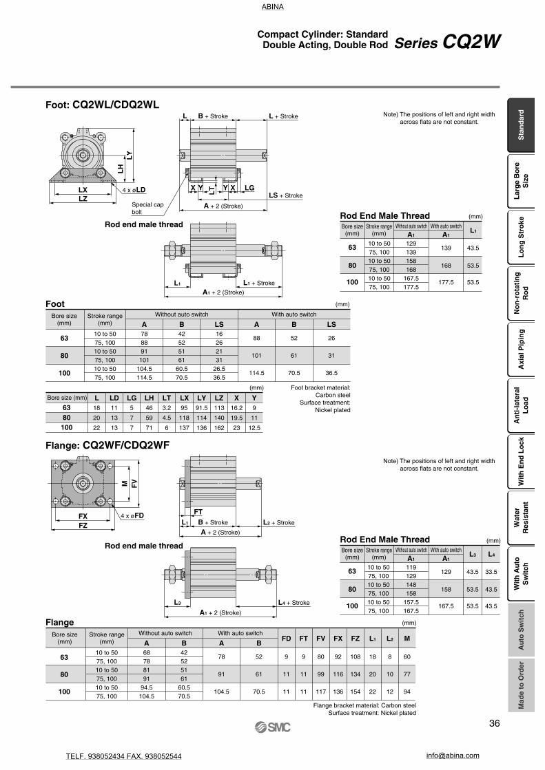
FXFZ
M FV
FTL1
L3
X Y XY
L
LG
LT
LZLX
LY
LH
L1
Special capbolt
4 x øLDLS + Stroke
B + Stroke
A + 2 (Stroke)
L + Stroke
L1 + Stroke
A1 + 2 (Stroke)
L4 + Stroke
A1 + 2 (Stroke)
L2 + StrokeB + Stroke
A + 2 (Stroke)
4 x øFD
(mm)
10 to 5075, 10010 to 5075, 10010 to 5075, 100
129139158168
167.5177.5
139
168
177.5
43.5
53.5
53.5
A1 A1L1
6380
100
11
13
13
5
7
7
46
59
71
3.2
4.5
6
95
118
137
91.5
114
136
113
140
162
16.2
19.5
23
9
11
12.5
(mm)
L LD LG LH LT LX LY LZ X Y18
20
22
(mm)
10 to 5075, 10010 to 5075, 10010 to 5075, 100
119129148158
157.5167.5
129
158
167.5
43.5
53.5
53.5
A1 A1L3
33.5
43.5
43.5
L4
63
80
100
(mm)
A B LS A B LS10 to 5075, 10010 to 5075, 10010 to 5075, 100
788891
101104.5114.5
42525161
60.570.5
16262131
26.536.5
88
101
114.5
52
61
70.5
26
31
36.5
8
10
12
(mm)
63
80
100
9
11
11
9
11
11
80
99
117
92
116
136
108
134
154
18
20
22
10 to 5075, 10010 to 5075, 10010 to 5075, 100
68788191
94.5104.5
42525161
60.570.5
78
91
104.5
52
61
70.5
A B A BFD FT FV FX FZ L1 L2
60
77
94
M
Foot: CQ2WL/CDQ2WLNote) The positions of left and right width
across flats are not constant.
Rod End Male ThreadBore size
(mm)Stroke range
(mm)Without auto switch With auto switch
63
80
100
Bore size (mm)
Foot bracket material:Carbon steel
Surface treatment: Nickel plated
FootBore size
(mm)Stroke range
(mm)Without auto switch With auto switch
Flange: CQ2WF/CDQ2WF
Rod End Male Thread
63
80
100
Without auto switch With auto switch
Note) The positions of left and right width across flats are not constant.
Bore size(mm)
Stroke range(mm)
FlangeBore size
(mm)Stroke range
(mm)Without auto switch With auto switch
Flange bracket material: Carbon steelSurface treatment: Nickel plated
Sta
nd
ard
Lar
ge
Bo
reS
ize
Lo
ng
Str
oke
No
n-r
ota
tin
gR
od
Axi
al P
ipin
gA
nti
-lat
eral
Lo
adW
ith
En
d L
ock
Wat
erR
esis
tan
tA
uto
Sw
itch
Mad
e to
Ord
erW
ith
Au
toS
wit
ch
36
Series CQ2WCompact Cylinder: StandardDouble Acting, Double Rod
Rod end male thread
Rod end male thread
ABINA
TELF. 938052434 FAX. 938052544 [email protected]


∗ ∗ Water resistant type auto switches can be mounted on the above models, but in such case SMC cannot guarantee water resistance. Consult with SMC regarding water resistant types with the above model numbers.
24 V —
M9NVM9PVM9BV
M9NWVM9PWVM9BWVM9NAV
∗∗
M9PAV ∗∗
M9BAV ∗∗
M9NM9PM9B
M9NWM9PWM9BW
M9NA ∗∗
M9PA ∗∗
M9BA ∗∗
—
—24 V
— A96V
A93VA90V
A96
A93A90
M9BW
10
S
32
32
CQ2 B
BCDQ2
Cylinder stroke (mm)Refer to the next page for standard strokes.
Bore size
S
Made to OrderRefer to the next page for details.
1020CQ2 B S
10
12162025324050
12 mm16 mm20 mm25 mm32 mm40 mm50 mm
Z
Z
Applicable Auto Switches/Refer to pages 1263 to 1371 in Best Pneumatics No. 2 for further information on auto switches.
How to Order
Compact Cylinder: StandardSingle Acting, Single Rod
Series CQ2ø12, ø16, ø20, ø25, ø32, ø40, ø50
With auto switch
Without auto switchø12 to ø25
Without auto switchø32 to ø50
With auto switch(Built-in magnet)
Through-hole (Standard)Both ends tapped
Foot
BAL
Rod flangeHead flangeDouble clevis
FGD
Mounting
∗ Mounting brackets are shipped together, (but not assembled).∗ Cylinder mounting bolts are not included. Order them
separately referring to “Mounting Bolt for C(D)Q2B” on pages 41 and 44.
Note) Bore sizes available with one-touch fittings are ø32 to ø50.
∗ For cylinders without auto switch, M threads are compatible only for ø32-5 mm stroke model.
Built-in one-touch fittings Note)
M threadRc
NPTG
ø12 to ø25
ø32 to ø50
Port thread type
Nil
TNTFF
Built-in Magnet Cylinder ModelIf a built-in magnet cylinder without an auto switch is required, there is no need to enter the symbol for the auto switch.(Example) CDQ2L32-10SZ
Number ofauto switches
NilSn
2 pcs.1 pc.
“n” pcs.
Auto switchNil Without auto switch
∗ Refer to the below table for applicable auto switches.
Auto switch mounting groove
Zø12 to ø25ø32 to ø50
2 surfaces4 surfaces
Body optionNilFM
StandardWith boss on head endRod end male thread
∗ Combination of body options (“FM”) is available.
ActionST
Single acting, Spring returnSingle acting, Spring extend
Type Special function Electricalentry
Wiring(Output)
Load voltage
DC AC
Lead wire length (m)
0.5(Nil)
3(L)
5(Z)
None(N)
Applicable loadPre-wiredconnector1
(M)
Auto switch model
Perpendicular In-line
Ind
ica
tor
ligh
t
IC circuit
—
IC circuit
—
IC circuit
—
Relay,PLC
—
Relay,PLC
IC circuit
—IC circuit
5 V,12 V12 V5 V,12 V12 V5 V,12 V12 V
—
100 V100 V or less
5 V
12 V5 V, 12 V
YesGrommet
3-wire (NPN)3-wire (PNP)
2-wire3-wire (NPN)3-wire (PNP)
2-wire3-wire (NPN)3-wire (PNP)
2-wire
Diagnostic indication(2-color indication)
Water resistant(2-color indication)
No
YesGrommet
3-wire(NPN equivalent)
2-wire
Ree
dau
to s
witc
hS
olid
sta
te a
uto
sw
itch
∗ Lead wire length symbols: 0.5 m ······· Nil (Example) M9NW1 m ········· M (Example) M9NWM3 m ········· L (Example) M9NWL5 m ········· Z (Example) M9NWZ
∗ Solid state auto switches marked with “” are produced upon receipt of order.
∗ There are other applicable auto switches other than the listed above. For details, refer to page 175.∗ For details about auto switches with pre-wired connector, refer to pages 1328 and 1329 in Best Pneumatics No. 2.
Sta
nd
ard
Lar
ge
Bo
reS
ize
Lo
ng
Str
oke
No
n-r
ota
tin
gR
od
Axi
al P
ipin
gA
nti
-lat
eral
Lo
adW
ith
En
d L
ock
Wat
erR
esis
tan
tA
uto
Sw
itch
Mad
e to
Ord
erW
ith
Au
toS
wit
ch
38
ABINA
TELF. 938052434 FAX. 938052544 [email protected]

Mounting
Bore size (mm)
Through-hole (Standard)
Both ends tapped
Pipe thread
Built-in magnet
Rod end male thread
With boss on head end
Piping
Built-in one-touch fittings Note 2)
12
M5 x 0.8
—
—
—
—
—
—
—
—
NPT1/8
G1/8
NPT1/8
G1/8
NPT1/4
G1/4
—
16
M5 x 0.8
—
20
M5 x 0.8
—
25
M5 x 0.8
—
32
ø6/4
40
ø6/4
50
ø8/6
Note 1)M5 x 0.8Rc1/8
Rc1/8 Rc1/4—
TN
TF
Note 1) ø32 without auto switch: M5 x 0.8 is used for 5 mm stroke piping dimension. Thus, do not enter a symbol for the port thread type.
Note 2) One-touch fittings cannot be replaced.
Type
Pne
umat
ic
-XA
-XB10
-XC6
-XC26
-XC27
-XC36
-X144
-X202
-X203
-X271
-X1876
Special rod end shape, spring return type only
Intermediate stroke (Exclusive body type),Spring return type only
Piston rod/Retaining ring/Rod end nutmaterial: Stainless steel
With split pins for double clevis pin/ double knuckle joint pin and flat washers
Double clevis pin/Double knuckle joint pin material: Stainless steel 304
With boss on rod end
Special port location, with auto switch ø12 to ø25 only
Full length dimension is the same as Series CQ1, Except ø12, ø16, ø25.
L dimension from rod cover is the same as Series CQ1, ø20, ø32 only.
Fluororubber seals
Cylinder tube: With concave boss on head end
Symbol Specifications
Specifications
Action
Fluid
Proof pressure
Maximum operating pressure
Minimum operating pressure (MPa)
Ambient and fluid temperature
Lubrication
Piston speed
Allowable kinetic energy (J)
Stroke length tolerance
Bore size (mm) 12 16 20 25 32 40 50
0.022 0.038 0.055 0.09 0.15 0.26
Single acting, Single rod
Air
1.5 MPa
1.0 MPa
Not required (Non-lube)
50 to 500 mm/s
0.46
0.25 0.25 0.18 0.18 0.17 0.15 0.13
Without auto switch: –10 to 70°C (No freezing)With auto switch: –10 to 60°C (No freezing)
+1.0 mm0
Bore size Standard stroke
5, 10
10, 20
(mm)
12, 16, 20, 25, 32, 40
50
Standard Strokes
Refer to “How to Order” for the standard model number. (P. 38)
Strokes in 1 mm intervals are available by installing a spacer in the standard stroke cylinder.
Bore size
12 to 40
50
Stroke range
1 to 9
1 to 19
Part no.: CQ2B20-3TCQ2B20-5T with 2 mm width spacer insideThe B dimension is 24.5 mm.
Type
Part no.
Description
Stroke range
Example
A spacer is installed in the standard stroke body.
Manufacture of Intermediate Strokes(Except single acting, spring return type)
JIS Symbol
Single acting, Spring return
Single acting, Spring extend
Made to Order(For details, refer to pages 177 to 207.)
• Auto switch proper mounting position (detection at stroke end) and its mounting height
• Minimum stroke for auto switch mounting• Operating range• Auto switch mounting brackets/Part no.
Refer to pages 169 to 175 for the specificationsof cylinders with auto switches.
39
Series CQ2
ABINA
TELF. 938052434 FAX. 938052544 [email protected]
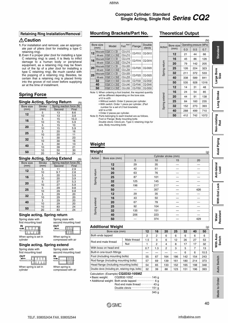
12
16
20
25
32
40
50
12
16
20
25
32
40
50
0.3
21
45
79
126
211
338
535
14
24
44
84
152
288
412
0.5
44
86
142
224
372
589
928
31
54
91
160
273
499
742
0.7
66
126
205
323
533
841
1316
48
85
138
235
393
710
1072
CautionRetaining Ring Installation/Removal
1. For installation and removal, use an appropri-ate pair of pliers (tool for installing a type C retaining ring).
2. Even if a proper plier (tool for installing a type C retaining ring) is used, it is likely to inflict damage to a human body or peripheral equipment, as a retaining ring may be flown out of the tip of a plier (tool for installing a type C retaining ring). Be much careful with the popping of a retaining ring. Besides, be certain that a retaining ring is placed firmly into the groove of rod cover before supplying air at the time of installment.
5 10 15 20
29
42
63
87
125
196
—
29
43
67
92
135
206
—
35
51
76
101
145
217
357
35
50
78
104
151
223
374
—
—
—
—
—
—
—
—
—
—
—
—
—
—
—
—
—
—
—
—
426
—
—
—
—
—
—
429
122
1.5
1
0.7
—
55
57
54
32
162
3
2
1.3
—
67
69
65
39
206
6
4
2
—
164
139
133
88
256
12
8
3
—
186
161
152
123
326
26
17
5
6
142
180
165
151
406
27
17
7
6
154
214
198
196
506
53
32
13
10.5
243
373
348
393
5105
105
105
105
105
101020
1313151515152020303030395054
8.63.9
10.35.9105.91611231613213024
12
16
20
25
32
40
50
5105
105
105
105
105
101020
119.7202027272929292929298383
2.92.83.93.95.35.99.89.8202020202424
12
16
20
25
32
40
50
(N)Single Acting, Spring Extend
12
16
20
25
Without switch
With switch
Without switch
With switch
Without switch
With switch
Without switch
With switch
324050
CQ-L012CQ-LZ12CQ-L016CQ-LZ16CQ-L020CQ-LZ20CQ-L025CQ-LZ25CQ-L032CQ-L040CQ-L050
CQ2-DCQ2-DZCQ2-DCQ2-DZCQ2-DCQ2-DZCQ2-DCQ2-DZCQ2-DZCQ2-DZCQ2-DZ
CQ-F012
CQ-F016
CQ-F020
CQ-F025
CQ-F032CQ-F040CQ-F050
CQ-D012
CQ-D016
CQ-D020
CQ-D025
CQ-D032CQ-D040CQ-D050
Spring Force
Bore size(mm)
Stroke(mm)
Spring reaction force (N)Second First
Bore size(mm)
Stroke(mm)
Spring reaction force (N)Second First
(N)Single Acting, Spring Return
INOUT
Spring state with first mounting load
Spring state with second mounting load
When spring is set in cylinder
When spring is compressed with air
Single acting, Spring extend
IN OUT
Spring state with first mounting load
Spring state with second mounting load
When spring is set in cylinder
When spring is compressed with air
Single acting, Spring return
Mounting Brackets/Part No. Theoretical Output
Bore size(mm) Foot
Note 1)Model Flange Double
clevis
Note 1) When ordering a foot bracket, the required quantity will be different depending on the bore size.ø12 to ø25:• Without switch: Order 2 pieces per cylinder.• With switch: Order 1 piece per cylinder. (Part
number for a set of 2 foot brackets)ø32 to ø100:• Order 2 pieces per cylinder.
Note 2) Parts belonging to each bracket are as follows.Foot or Flange: Body mounting boltsDouble clevis: Clevis pin, Type C retaining rings for axis, Body mounting bolts
(N)
Bore size(mm)Action
Operating pressure (MPa)
Spr
ing
retu
rnS
prin
g ex
tend
Action Bore size (mm)Cylinder stroke (mm)
(g)Weight
Weight
Spr
ing
retu
rnS
prin
g ex
tend
1216202532405012162025324050
Bore size (mm)
(g)Additional Weight
Both ends tapped
Rod end male thread
With boss on head end
Built-in one-touch fittings
Foot (Including mounting bolts)
Rod flange (Including mounting bolts)
Head flange (Including mounting bolts)
Double clevis (Including pin, retaining rings, bolts)
Male thread
Nut
Calculation: (Example) CQ2D32-10SMZ• Basic weight: CQ2B32-10SZ• Additional weight: Both ends tapped
Rod end male threadDouble clevis
345 g
145 g6 g
43 g151 g
Sta
nd
ard
Lar
ge
Bo
reS
ize
Lo
ng
Str
oke
No
n-r
ota
tin
gR
od
Axi
al P
ipin
gA
nti
-lat
eral
Lo
adW
ith
En
d L
ock
Wat
erR
esis
tan
tA
uto
Sw
itch
Mad
e to
Ord
erW
ith
Au
toS
wit
ch
40
Series CQ2Compact Cylinder: StandardSingle Acting, Single Rod
ABINA
TELF. 938052434 FAX. 938052544 [email protected]

C Mounting bolt part no.
6.5
5
7.5
9.5
9
7.5
12.5
D2530253025303035303535404555
CQ2B12-5S -10S
CQ2B16-5S -10S
CQ2B20-5S -10S
CQ2B25-5S -10S
CQ2B32-5SZ -10SZ
CQ2B40-5SZ -10SZ
CQ2B50-10SZ-20SZ
CQ-M3 x 25L x 30L
CQ-M3 x 25L x 30L
CQ-M5 x 25L x 30L
CQ-M5 x 30L x 35L
CQ-M5 x 30L x 35L
CQ-M5 x 35L x 40L
CQ-M6 x 45L x 55L
C Mounting bolt part no.
6.5
5
7.5
9.5
9
7.5
12.5
D2530253025303035303535404555
CQ2B12-5T -10T
CQ2B16-5T -10T
CQ2B20-5T -10T
CQ2B25-5T -10T
CQ2B32-5TZ -10TZ
CQ2B40-5TZ -10TZ
CQ2B50-10TZ-20TZ
CQ-M3 x 25L x 30L
CQ-M3 x 25L x 30L
CQ-M5 x 25L x 30L
CQ-M5 x 30L x 35L
CQ-M5 x 30L x 35L
CQ-M5 x 35L x 40L
CQ-M6 x 45L x 55L
Mounting Bolt for CQ2B/Without Auto Switch
Mounting method: Mounting bolt for through-hole mounting of the CQ2B is available as an option. Refer to the following for ordering procedures. Order the actual number of bolts that will be used.
Example) CQ-M3x25L 4 pcs.
Material: Chromium molybdenum steelSurface treatment: Nickel plated
Mounting bolt
Cylinder model
Spring ReturnCylinder model
Spring Extend
Mounting bolt
41
Series CQ2
ABINA
TELF. 938052434 FAX. 938052544 [email protected]

∗ Seal kit includes !4. Order the seal kit, based on each bore size.
12162025324050
Contents
How toOrder
Single acting/Spring return
CQ2B12-S-PS
CQ2B16-S-PS
CQ2B20-S-PS
CQ2B25-S-PS
CQ2B32-S-PS
CQ2B40-S-PS
CQ2B50-S-PS
Kits includes item !4 from the above table.
Single acting/Spring extend
CQ2B12-T-PS
CQ2B16-T-PS
CQ2B20-T-PS
CQ2B25-T-PS
CQ2B32-T-PS
CQ2B40-T-PS
CQ2B50-T-PS
Kits include items !4, !5, !6 from the above table.
Replacement Parts/Seal KitBore size
(mm)
∗ Seal kit includes !4, !5, !6. Order the seal kit, based on each bore size.
∗ Since the seal kit does not include a grease pack, order it separately. Grease pack part no.: GR-S-010 (10 g)
Construction
Spring return Spring extend
With boss on head end Rod end male thread Built-in one-touch fittings
Port sizeM5 x 0.8
∗
Component PartsNo.12
3
4
56789
10111213
DescriptionCylinder tubePiston
Piston rod
Collar
Retaining ringBushingReturn springBronze elementRetaining ringPlug with fixed orificeRod end nutCentering location ringOne-touch fitting
NoteHard anodized
Chromatedø12 to ø25
ø32 to ø50, Hard chrome platedø12 to ø40, Anodized
ø50, Chromated, PaintedPhosphate coated
ø50Zinc chromated
Port size Rc1/8, 1/4
Port size M5 x 0.8Nickel plated
ø20 to ø50, Anodizedø32 to ø50
∗ On spring extend (Type T), piston and piston rod are integrated (stainless steel). (Except ø12 and ø16 of built-in magnet type)
Replacement PartsNo.141516
DescriptionPiston sealRod sealGasket
MaterialNBRNBRNBR
Note
ø12, ø16, ø20, ø25, ø32ø40, ø50
Bore size Stroke20 CQ2B ST
Copper and fluorine-free series
For preventing the influence of copper ions or halogen ions during CRT manufacturing processes, copper and fluorine materials are not used in the component parts.
(M)Z
Copper and Fluorine-free Series (For CRT Manufacturing Process)
SpecificationsBore size (mm)
Action
Proof pressure
Max. operating pressure
Rubber bumper
Piping
Piston speed
Mounting
Auto switch
Single acting, Single rod
1.5 MPa
1.0 MPa
None
Pipe thread
50 to 500 mm/s
Through-hole
Mountable
12 16 20 25 32 40 50
Sta
nd
ard
Lar
ge
Bo
reS
ize
Lo
ng
Str
oke
No
n-r
ota
tin
gR
od
Axi
al P
ipin
gA
nti
-lat
eral
Lo
adW
ith
En
d L
ock
Wat
erR
esis
tan
tA
uto
Sw
itch
Wit
h A
uto
Sw
itch
Mad
e to
Ord
er
42
Series CQ2Compact Cylinder: StandardSingle Acting, Single Rod
MaterialAluminum alloyAluminum alloyStainless steelCarbon steel
Aluminum alloyAluminum alloy casted
Carbon tool steelBearing alloyPiano wire
Sintered metallic BCCarbon tool steel
Alloy steelCarbon steel
Aluminum alloy—
ABINA
TELF. 938052434 FAX. 938052544 [email protected]

121
1.5
1
0.7
—
49
54
52
29
161
3
2
1.3
—
62
67
63
35
203
6
4
2
—
147
131
124
78
253
12
8
3
—
169
153
144
114
326
26
17
5
6
142
180
165
151
406
27
17
7
6
154
214
198
196
506
53
32
13
10.5
243
373
348
393
1216202532405012162025324050
5 10 15 20
44
64
97
135
182
269
—
49
63
110
149
192
279
—
49
72
109
150
202
290
456
65
71
119
163
208
296
486
—
—
—
—
—
—
—
—
—
—
—
—
—
—
—
—
—
—
—
—
521
—
—
—
—
—
—
540
Refer to the below pages for further information on auto switches.Auto switch proper mounting position and its mounting height
Minimum stroke for auto switch mounting
Operating range
Auto switch mounting brackets/Part no.
P.169 to 175
Standard: Single Acting, Single Rod
Series CDQ2With Auto Switch
Weight
Weight
Action Bore size(mm)
Cylinder stroke (mm)
Spr
ing
retu
rnS
prin
g ex
tend
(g)
Bore size (mm)
Additional Weight
Both ends tapped
With boss on head end
Built-in one-touch fittings
Foot (Including mounting bolts)
Rod flange (Including mounting bolts)
Head flange (Including mounting bolts)
Double clevis (Including pin, retaining rings, bolts)
Male thread
NutRod end male thread
(g)
Add each weight of auto switches when auto switches are mounted.
Calculation: (Example) CDQ2D32-10SMZ• Basic weight: CDQ2B32-10SZ• Additional weight: Both ends tapped
Rod end male threadDouble clevis
202 g6 g
43 g151 g
402 g
Port sizeM5 x 0.8
Spring extendSpring return
Construction
No.12
3
4
56789
1011
DescriptionCylinder tubePiston
Piston rod
Collar
Retaining ringBushingReturn springBronze elementRetaining ringPlug with fixed orificeMagnet
MaterialAluminum alloyAluminum alloyStainless steelCarbon steel
Aluminum alloyAluminum alloy casted
Carbon tool steelBearing alloyPiano wire
Sintered metallic BCCarbon tool steel
Alloy steel—
NoteHard anodized
Chromatedø12 to ø25
ø32 to ø50, Hard chrome platedø12 to ø40, Anodized
ø50, Chromated, PaintedPhosphate coated
ø50Zinc chromated
Port size Rc1/8, 1/4
Port size M5 x 0.8
∗ On spring extend (Type T), piston with ø20 or more and piston rod are integrated (stainless steel).
Component PartsNo.121314
DescriptionPiston sealRod sealGasket
MaterialNBRNBRNBR
Note
Replacement Parts/Seal Kit
Since the same as those of the standard, single acting, single rod, refer to page 42.
43
ABINA
TELF. 938052434 FAX. 938052544 [email protected]

C Mounting bolt part no.
5.5
8
10.5
9.5
9
7.5
12.5
D3540404540454045404545505565
CDQ2B12-5SZ -10SZ
CDQ2B16-5SZ -10SZ
CDQ2B20-5SZ -10SZ
CDQ2B25-5SZ -10SZ
CDQ2B32-5SZ -10SZ
CDQ2B40-5SZ -10SZ
CDQ2B50-10SZ-20SZ
CQ-M3 x 35L x 40L
CQ-M3 x 40L x 45L
CQ-M5 x 40L x 45L
CQ-M5 x 40L x 45L
CQ-M5 x 40L x 45L
CQ-M5 x 45L x 50L
CQ-M6 x 55L x 65L
C Mounting bolt part no.
6.1
8
10.5
9.5
9
7.5
12.5
D4045404540454045404545505565
CDQ2B12-5TZ -10TZ
CDQ2B16-5TZ -10TZ
CDQ2B20-5TZ -10TZ
CDQ2B25-5TZ -10TZ
CDQ2B32-5TZ -10TZ
CDQ2B40-5TZ -10TZ
CDQ2B50-10TZ-20TZ
CQ-M3 x 40L x 45L
CQ-M3 x 40L x 45L
CQ-M5 x 40L x 45L
CQ-M5 x 40L x 45L
CQ-M5 x 40L x 45L
CQ-M5 x 45L x 50L
CQ-M6 x 55L x 65L
Material: Chromium molybdenum steelSurface treatment: Nickel plated
Mounting Bolt for CDQ2B/With Auto Switch
Mounting method: Mounting bolt for through-hole mounting of the CDQ2B is available as an option. Refer to the following for ordering procedures. Order the actual number of bolts that will be used.
Example) CQ-M3x35L 2 pcs.
Spring return Spring extendMounting bolt Mounting bolt
Cylinder model
Spring ReturnCylinder model
Spring Extend
Sta
nd
ard
Lar
ge
Bo
reS
ize
Lo
ng
Str
oke
No
n-r
ota
tin
gR
od
Axi
al P
ipin
gA
nti
-lat
eral
Lo
adW
ith
En
d L
ock
Wat
erR
esis
tan
tA
uto
Sw
itch
Wit
h A
uto
Sw
itch
Mad
e to
Ord
er
44
Series CQ2Compact Cylinder: StandardSingle Acting, Single Rod
ABINA
TELF. 938052434 FAX. 938052544 [email protected]

H1
C1
XL1
MM
øI
EMZ
K
M
E
RR
øD
F
L BA
G
øT
h9
H thread effective depth C
8 x øO counterbore
4 x øN through
O1 thread
(Port size)
M5 x 0.8
Width across flat B1
12162025
O1
M4 x 0.7M4 x 0.7M6 x 1.0M6 x 1.0
R
77
1010
12162025
B1
8101317
X
10.51214
17.5
L1
1415.518.522.5
C1
9101215
H1
4556
MM
M5 x 0.8M6 x 1.0
M8 x 1.25M10 x 1.25
(mm)
12
16
20
25
510510510510
C
6
8
7
12
B
2227
23.528.524.529.527.532.5
A
25.530.527322934
32.537.5
D
6
8
10
12
E
25
29
36
40
F
5
5.5
5.5
5.5
H
M3 x 0.5
M4 x 0.7
M5 x 0.8
M6 x 1.0
I
32
38
47
52
K
5
6
8
10
L
3.5
3.5
4.5
5
M
15.5
20
25.5
28
N
3.5
3.5
5.5
5.5
O
6.5 depth 3.5
6.5 depth 3.5
9 depth 7
9 depth 7
Z
—
10
10
10
(mm)
ø12 to ø25/Spring Return Without Auto Switch
Dimensions
Standard (Through-hole): CQ2B
Both ends tapped: CQ2A
Bore size(mm)
Both EndsTapped (mm)
With boss on head end
Bore size(mm)
12162025
1.51.522
G Th9
15201315
0–0.043
0–0.052
0–0.043
0–0.043
Note) With boss on rod end: Option (Suffix “-XC36” to the end of model number.)
With Boss on Head End (mm)
Rod end male thread
Rod End Male ThreadBore size
(mm)
StandardBore size
(mm)Stroke(mm)
∗ For details about the rod end nut and accessory brackets, refer to page 19.
45
Series CQ2
ABINA
TELF. 938052434 FAX. 938052544 [email protected]

øCB
LH
LY
LZLX
L
LGLT Y XYX
LS
B
A
L1
FV
FXFZ
L1
FT
LA
B
FV
FXFZ
LA
FTB
L1
L1
CT
RRCU
CWL BCL
A
CZ –0.1–0.3
CX +0.4+0.2
4 x øLD
Special cap bolt
2 x øFD
2 x øFD
Cap bolt4 x N
Axis d9øCD hole H10
12162025
5st40.341.846.249.7
10st45.346.851.254.7
5st22
23.524.527.5
10st27
28.529.532.5
L
13.513.514.515
L1
2425.528.532.5
LD
4.54.56.66.6
LG
2.82.844
LH
17192426
5st10
11.512.512.5
10st15
16.517.517.5
A B
12162025
5st35.53739
42.5
10st40.54244
47.5
5st22
23.524.527.5
10st27
28.529.532.5
FD
4.54.56.66.6
FT
5.55.588
FV
25303942
FX
45454852
FZ
55556064
L
13.513.514.515
L1
2425.528.532.5
A
12162025
5st31
32.537
40.5
10st36
37.542
45.5
L
3.53.54.55
L1
1415.518.522.5
A
B
LS(mm)
12162025
LT
22
3.23.2
LX
34384852
LY
29.533.54246
LZ
44486266
X
88
9.210.7
Y
4.55
5.85.8
(mm)
12162025
5st45.54856
62.5
10st50.55361
67.5
CD
558
10
CT
4455
CU
7101214
CW
14151820
A5st22
23.524.527.5
10st27
28.529.532.5
B5st
39.54247
52.5
10st44.54752
57.5
CL(mm)
CB
12142024
12162025
CX
56.58
10
CZ
10121620
L
3.53.54.55
L1
1415.518.522.5
RR
669
10
N
M4 x 0.7M4 x 0.7M6 x 1.0M6 x 1.0
Foot: CQ2L
Rod flange: CQ2F
Head flange: CQ2G
Double clevis: CQ2D
Rod end male thread
Rod end male thread
Rod end male thread
Rod end male thread
FootBore size
(mm)
Bore size(mm)
Foot bracket material: Carbon steelSurface treatment: Nickel plated
Rod FlangeBore size
(mm)
Flange bracket material: Carbon steelSurface treatment: Nickel plated
Bore size(mm)
Flange bracket material: Carbon steelSurface treatment: Nickel plated
Head Flange (mm)
∗ The dimensions except A, L and L1 are the same as those of the rod flange.
Double ClevisBore size
(mm)
Bore size(mm)
Double clevis bracket material: Carbon steelSurface treatment: Nickel plated
∗ For details about the rod end nut and accessory brackets, refer to page 19.∗ Double clevis pin and retaining rings are included.
Sta
nd
ard
Lar
ge
Bo
reS
ize
Lo
ng
Str
oke
No
n-r
ota
tin
gR
od
Axi
al P
ipin
gA
nti
-lat
eral
Lo
adW
ith
En
d L
ock
Wat
erR
esis
tan
tA
uto
Sw
itch
Mad
e to
Ord
erW
ith
Au
toS
wit
ch
46
Series CQ2Compact Cylinder: StandardSingle Acting, Single Rod
ABINA
TELF. 938052434 FAX. 938052544 [email protected]

S
U
EB
EA
E
M
K
H1
C1
X
L1
G
øT
h9
RR
øD
FL B
A
MM
ø12
ø16 to ø25
K
M
E
S
U
O1 thread
V
Auto switch
Minimum lead wire bending radius 10
H thread effective depth C
2 x øN through4 x øO counterbore M5 x 0.8
(Port size)
Width across flat B1
2 x øN through4 x øO counterbore
H thread effective depth C 8
V
12162025
O1
M4 x 0.7M4 x 0.7M6 x 1.0M6 x 1.0
R
77
1010
12162025
B1
8101317
X
10.51214
17.5
L1
1415.518.522.5
C1
9101215
H1
4556
MM
M5 x 0.8M6 x 1.0M8 x 1.25M10 x 1.25
(mm)
12
16
20
25
Standard For auto switch proper mounting position and its mounting height, refer to pages 169 to 175.
510510510510
C
6
8
7
12
B
3338
35.540.536.541.537.542.5
A
36.541.539444146
42.547.5
D
6
8
10
12
E
33
37
47
52
EA
—
13.2
13.6
13.6
EB
—
6.6
6.8
6.8
F
6.5
5.5
5.5
5.5
H
M3 x 0.5
M4 x 0.7
M5 x 0.8
M6 x 1.0
K
5
6
8
10
L
3.5
3.5
4.5
5
M
22
28
36
40
N
3.5
3.5
5.5
5.5
O
6.5 depth 3.5
6.5 depth 3.5
9 depth 7
9 depth 7
S
27.5
29.5
35.5
40.5
U
14
15
18
21
V
25
29
36
40
(mm)
ø12 to ø25/Spring Return With Auto Switch
Dimensions
Standard (Through-hole): CDQ2B
Both ends tapped: CDQ2A
With boss on head end
Rod end male thread
Bore size(mm)
Both EndsTapped (mm)
Bore size(mm)
12162025
G
1.51.522
Th9
15201315
0–0.043
0–0.052
0–0.043
0–0.043
Note) With boss on rod end: Option (Suffix “-XC36” to the end of model number.)
With Boss on Head End (mm)
Rod End Male ThreadBore size
(mm)
Bore size(mm)
Stroke(mm)
∗ For details about the rod end nut and accessory brackets, refer to page 19.
47
Series CQ2
ABINA
TELF. 938052434 FAX. 938052544 [email protected]

øCB
X Y XYLT
LG
L
L1
A
B
LS
FZFX
FV
LFT L1
AB
L BFZFX
FV
AFT
L1
L B
ACL
L1
CU
CT
CW RR
LXLZ
LY
LH
Special cap bolt
2 x øFD
2 x NCap bolt
øCD hole H10Axis d9
4 x øLD
CX+0.4+0.2
CZ
2 x øFD
–0.1–0.3
12162025
5st51.353.858.259.7
10st56.358.863.264.7
5st33
35.536.537.5
10st38
40.541.542.5
L
13.513.514.515
L1
2425.528.532.5
LD
4.54.56.66.6
LG
2.82.844
LH
17192426
5st21
23.524.522.5
10st26
28.529.527.5
A B
12162025
5st46.54951
52.5
10st51.55456
57.5
5st33
35.536.537.5
10st38
40.541.542.5
FD
4.54.56.66.6
FT
5.55.588
FV
25303942
FX
45454852
FZ
55556064
L
13.513.514.515
L1
2425.528.532.5
A
12162025
5st46.444.549
50.5
10st51.449.554
55.5
L
3.53.54.55
L1
1415.518.522.5
A
B
LS(mm)
(mm)
(mm)
12162025
5st56.56068
72.5
10st61.56573
77.5
CD
558
10
CT
4455
CU
7101214
CW
14151820
A5st33
35.536.537.5
10st38
40.541.542.5
B5st
50.55459
62.5
10st55.55964
67.5
CL(mm)
CB
12142024
12162025
CX
56.58
10
CZ
10121620
L
3.53.54.55
L1
1415.518.522.5
RR
669
10
N
M4 x 0.7M4 x 0.7M6 x 1.0M6 x 1.0
12162025
LT
22
3.23.2
LX
34384852
LY
29.533.54246
LZ
44486266
X
88
9.210.7
Y
4.55
5.85.8
Foot: CDQ2L
Rod flange: CDQ2F
Head flange: CDQ2G
Double clevis: CDQ2D
Rod end male thread
Rod end male thread
Rod end male thread
Rod end male thread
FootBore size
(mm)
Bore size(mm)
Foot bracket material: Carbon steelSurface treatment: Nickel plated
Rod FlangeBore size
(mm)
Flange bracket material: Carbon steelSurface treatment: Nickel plated
Head FlangeBore size
(mm)
Flange bracket material: Carbon steelSurface treatment: Nickel plated
∗ The dimensions except A, L and L1 are the same as those of the rod flange.
Double ClevisBore size
(mm)
Bore size(mm)
∗ For details about the rod end nut and accessory brackets, refer to page 19.∗ Double clevis pin and retaining rings are included.
Double clevis bracket material: Carbon steelSurface treatment: Nickel plated
Sta
nd
ard
Lar
ge
Bo
reS
ize
Lo
ng
Str
oke
No
n-r
ota
tin
gR
od
Axi
al P
ipin
gA
nti
-lat
eral
Lo
adW
ith
En
d L
ock
Wat
erR
esis
tan
tA
uto
Sw
itch
Mad
e to
Ord
erW
ith
Au
toS
wit
ch
48
Series CQ2Compact Cylinder: StandardSingle Acting, Single Rod
ABINA
TELF. 938052434 FAX. 938052544 [email protected]

W1
V
øZ
1
Z M E
JWEM
K
H1
RR
øD
F
L BA
2
øT
h9
C1
XL1
MM
4 x øN through8 x øO counterbore
H thread effective depth C Auto switch
Minimum lead wirebending radius 10
P (Rc, NPT, G)(Port size)
P1
(Piping tube O.D.)
Width across flat B1
O1 thread
324050
O1
M6 x 1.0M6 x 1.0M8 x 1.25
R
101014
324050
B1
222227
324050
Z1
131316
P1
668
V
36.540.550
W1
5966.582
X
23.523.528.5
MM
M14 x 1.5M14 x 1.5M18 x 1.5
C1
20.520.526
H1
88
11
(mm)
Standard For auto switch proper mounting position and its mounting height, refer to pages 169 to 175.
32
40
50
35
40
41.5
46.5
48.5
58.5
5
10
5
10
10
20
28
33
34.5
39.5
40.5
50.5
5.5
7.5
8
8
10.5
10.5
M5 x 0.8
1/8
1/8
1/4
45
50
51.5
56.5
58.5
68.5
38
43
44.5
49.5
50.5
60.5
(mm)
7.5
8
10.5
1/8
1/8
1/4
A B F P A B F P
16
16
20
45
52
64
M8 x 1.25
M8 x 1.25
M10 x 1.5
4.5
5
7
14
14
17
7
7
8
34
40
50
C D E H J K L M
5.5
5.5
6.6
N
9 depth 7
9 depth 7
11 depth 8
O
49.5
57
71
W
13
13
15
14
15
19
Z
L1
28.528.533.5
ø32 to ø50/Spring Return With Auto Switch
(In the case of without auto switches, the A, B, F and P dimensions will be only changed. Refer to the dimension table.)
Dimensions
Standard (Through-hole):CQ2B/CDQ2B
Built-in one-touch fittings: ø32 to ø50
Both ends tapped: CQ2A/CDQ2A
With boss on head end
Rod end male thread
Bore size(mm)
Both EndsTapped (mm)
Bore size(mm)
324050
Th9
212835
0–0.052
0–0.052
0–0.062
Note 1) With boss on rod end: Option (Suffix “-XC36” to the end of model number.)
With Boss on Head End (mm)
Rod End Male ThreadBore size
(mm)
Bore size(mm)
Built-in One-touch Fittings (mm)
Bore size(mm)
Stroke(mm)
Without auto switch With auto switch
Note 2) The A, B dimensions of the ø32-5 mm stroke with built-in one-touch fittings without auto switch are the same as those of the ø32-10 mm stroke without auto switch.
∗ For details about the rod end nut and accessory brackets, refer to page 19.
49
Series CQ2
ABINA
TELF. 938052434 FAX. 938052544 [email protected]
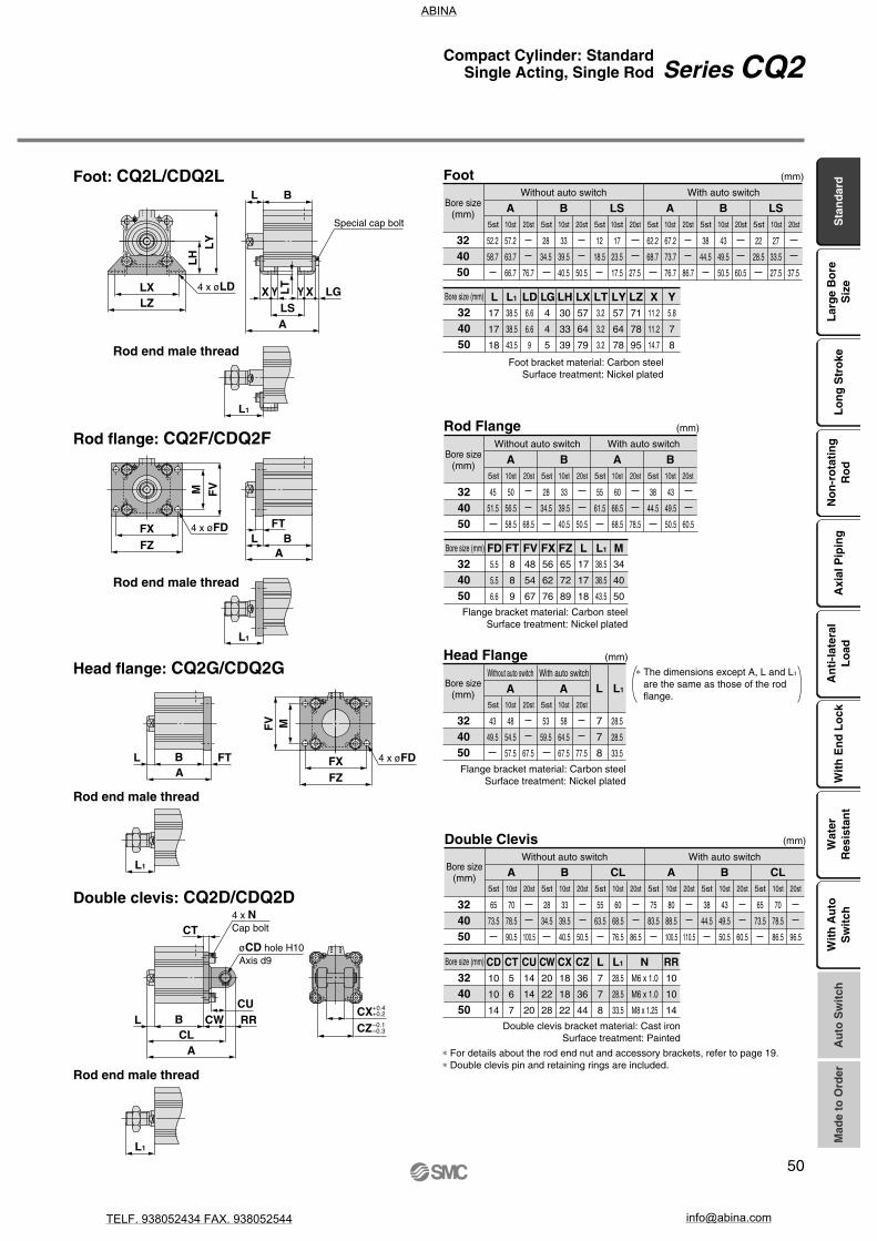
MFV
FXFZ
L1
L1
L1
FTL B
A
M FV
FXFZ
CT
CURRCWL B
CLA
FTA
L B
LZLX
LY
LH
ALS
X Y XYLT
BL
LG
L1
CXCZ
4 x øFD
4 x øFD
øCD hole H10Axis d9
4 x NCap bolt
+0.4+0.2
–0.1–0.3
Special cap bolt
4 x øLD
324050
57.2
63.7
66.7
52.2
58.7
76.7
33
39.5
40.5
28
34.5
50.5
17
23.5
17.5
12
18.5
27.5
67.2
73.7
76.7
62.2
68.7
86.7
43
49.5
50.5
38
44.5
60.5
27
33.5
27.5
22
28.5
37.5
(mm)
5st 10st 20st 5st 10st 20st 5st 10st 20st 5st 10st 20st 5st 10st 20st 5st 10st 20st
A B LS A B LS
324050
38.5
38.5
43.5
6.6
6.6
9
4
4
5
30
33
39
57
64
79
57
64
78
71
78
95
11.2
11.2
14.7
5.8
7
8
L L1 LD LG LH LX3.2
3.2
3.2
LT LY LZ X Y17
17
18
324050
70
78.5
90.5
65
73.5
100.5
33
39.5
40.5
28
34.5
50.5
60
68.5
76.5
55
63.5
86.5
80
88.5
100.5
75
83.5
110.5
43
49.5
50.5
38
44.5
60.5
70
78.5
86.5
65
73.5
96.5
(mm)
5st 10st 20st 5st 10st 20st 5st 10st 20st 5st 10st 20st 5st 10st 20st 5st 10st 20st
A B CL A B CL
324050
5
6
7
14
14
20
20
22
28
18
18
22
36
36
44
7
7
8
28.5
28.5
33.5
M6 x 1.0
M6 x 1.0
M8 x 1.25
10
10
14
CD CT CU CW CX CZ L L1 N RR10
10
14
324050
50
56.5
58.5
45
51.5
68.5
33
39.5
40.5
28
34.5
50.5
60
66.5
68.5
55
61.5
78.5
43
49.5
50.5
38
44.5
(mm)
5st 10st 20st 5st 10st 20st 5st 10st 20st 5st 10st
60.5
20st
A B A B
324050
8
8
9
48
54
67
56
62
76
65
72
89
17
17
18
38.5
38.5
43.5
34
40
50
FD FT FV FX FZ L L1 M5.5
5.5
6.6
324050
48
54.5
57.5
43
49.5
67.5
58
64.5
67.5
53
59.5
77.5
28.5
28.5
33.5
7
7
8
(mm)
5st 10st 20st 5st 10st 20st
A A L L1
Foot: CQ2L/CDQ2L
Rod end male thread
Rod flange: CQ2F/CDQ2F
Rod end male thread
Head flange: CQ2G/CDQ2G
Rod end male thread
Double clevis: CQ2D/CDQ2D
Rod end male thread
Foot
Bore size(mm)
Without auto switch With auto switch
Bore size (mm)
Foot bracket material: Carbon steelSurface treatment: Nickel plated
Rod Flange
Bore size(mm)
Without auto switch With auto switch
Bore size (mm)
Flange bracket material: Carbon steelSurface treatment: Nickel plated
Head Flange
Bore size(mm)
Without auto switch With auto switch
Flange bracket material: Carbon steelSurface treatment: Nickel plated
∗ The dimensions except A, L and L1 are the same as those of the rod flange.
Double Clevis
Bore size(mm)
Without auto switch With auto switch
Bore size (mm)
Double clevis bracket material: Cast ironSurface treatment: Painted
∗ For details about the rod end nut and accessory brackets, refer to page 19.∗ Double clevis pin and retaining rings are included.
Sta
nd
ard
Lar
ge
Bo
reS
ize
Lo
ng
Str
oke
No
n-r
ota
tin
gR
od
Axi
al P
ipin
gA
nti
-lat
eral
Lo
adW
ith
En
d L
ock
Wat
erR
esis
tan
tA
uto
Sw
itch
Mad
e to
Ord
erW
ith
Au
toS
wit
ch
50
Series CQ2Compact Cylinder: StandardSingle Acting, Single Rod
ABINA
TELF. 938052434 FAX. 938052544 [email protected]

H1
C1
X
L1
MM
RR
øI
EMZ
K
M
E
QøD
L B
A
G
øT
h9
Width across flat B1
O1 thread
H thread effective depth C
(Port size)M5 x 0.8
4 x øN through8 x øO counterbore
12162025
O1
M4 x 0.7M4 x 0.7M6 x 1.0M6 x 1.0
R
77
1010
12162025
B1
8101317
X
10.51214
17.5
MM
M5 x 0.8M6 x 1.0M8 x 1.25M10 x 1.25
C1
9101215
H1
4556
5st1920.523.527.5
10st2425.528.532.5
L1
(mm)
12
16
20
25
30.540.532423444
37.547.5
2227
23.528.524.529.527.532.5
C
6
8
7
12
D
6
8
10
12
E
25
29
36
40
H
M3 x 0.5
M4 x 0.7
M5 x 0.8
M6 x 1.0
I
32
38
47
52
K
5
6
8
10
M
15.5
20
25.5
28
N
3.5
3.5
5.5
5.5
O
6.5 depth 3.5
6.5 depth 3.5
9 depth 7
9 depth 7
Z
—
10
10
10
Q
7.5
8
9
11
(mm)
A B
8.513.58.5
13.59.5
14.51015
L
510510510510
ø12 to ø25/Spring Extend Without Auto Switch
Dimensions
Standard (Through-hole): CQ2B
With boss on head end
Rod end male thread
Both ends tapped: CQ2A
Bore size(mm)
Both EndsTapped (mm)
Bore size(mm)
12162025
G
1.51.522
Th9
15201315
0–0.043
0–0.052
0–0.043
0–0.043
Note) With boss on rod end: Option (Suffix “-XC36” to the end of model number.)
With Boss on Head End (mm)
Rod End Male ThreadBore size
(mm)
StandardBore size
(mm)
∗ For details about the rod end nut and accessory brackets, refer to page 19.
Stroke(mm)
51
Series CQ2
ABINA
TELF. 938052434 FAX. 938052544 [email protected]
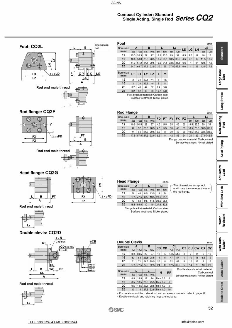
øCB
L1
L
LGLT Y XYX
LS
B
A
FTL
AB
L1
FV
FXFZ
LA
FTB
L1
L1
CT
RRCU
CWL BCL
A
LH
LY
LZLX
FV
FXFZ
CX +0.4+0.2
CZ –0.1–0.3
Special cap bolt
2 x øFD
Cap bolt4 x N
øCD hole H10Axis d9
4 x øLD
2 x øFD
12162025
5st45.346.851.254.7
10st55.356.861.264.7
5st22
23.524.527.5
10st27
28.529.532.5
5st18.518.519.520
10st23.523.524.525
5st29
30.533.537.5
10st34
35.538.542.5
LD
4.54.56.66.6
LG
2.82.844
LH
17192426
5st10
11.512.512.5
10st15
16.517.517.5
A B L L1
12162025
5st40.54244
47.5
10st50.55254
57.5
5st22
23.524.527.5
5st18.518.519.520
10st27
28.529.532.5
10st23.523.524.525
5st29
30.533.537.5
10st34
35.538.542.5
FD
4.54.56.66.6
FT
5.55.588
FV
25303942
FX
45454852
FZ
55556064
A L
12162025
5st36
37.542
45.5
10st46
47.552
55.5
A
B L1
LS(mm)
(mm)
5st8.58.59.510
10st13.513.514.515
L5st19
20.523.527.5
10st24
25.528.532.5
L1
(mm)
12162025
5st50.55361
67.5
10st60.56371
77.5
CD
55810
CT
4455
CU
7101214
CW
14151820
CX
56.5810
CZ
10121620
A5st22
23.524.527.5
10st27
28.529.532.5
B5st
44.54752
57.5
10st54.55762
67.5
CL(mm)
CB
12142024
12162025
RR
66910
N
M4 x 0.7M4 x 0.7M6 x 1.0M6 x 1.0
5st8.58.59.510
10st13.513.514.515
L5st19
20.523.527.5
10st24
25.528.532.5
L1
12162025
LT
22
3.23.2
LX
34384852
LY
29.533.54246
LZ
44486266
X
88
9.210.7
Y
4.55
5.85.8
Foot: CQ2L
Rod flange: CQ2F
Head flange: CQ2G
Double clevis: CQ2D
Rod end male thread
Rod end male thread
Rod end male thread
Rod end male thread
FootBore size
(mm)
Bore size(mm)
Foot bracket material: Carbon steelSurface treatment: Nickel plated
Rod FlangeBore size
(mm)
Flange bracket material: Carbon steelSurface treatment: Nickel plated
Head FlangeBore size
(mm)
Flange bracket material: Carbon steelSurface treatment: Nickel plated
∗ The dimensions except A, L and L1 are the same as those of the rod flange.
Double ClevisBore size
(mm)
Bore size(mm)
Double clevis bracket material:Carbon steel
Surface treatment: Nickel plated
∗ For details about the rod end nut and accessory brackets, refer to page 19.∗ Double clevis pin and retaining rings are included.
Sta
nd
ard
Lar
ge
Bo
reS
ize
Lo
ng
Str
oke
No
n-r
ota
tin
gR
od
Axi
al P
ipin
gA
nti
-lat
eral
Lo
adW
ith
En
d L
ock
Wat
erR
esis
tan
tA
uto
Sw
itch
Mad
e to
Ord
erW
ith
Au
toS
wit
ch
52
Series CQ2Compact Cylinder: StandardSingle Acting, Single Rod
ABINA
TELF. 938052434 FAX. 938052544 [email protected]

S
U
EB
EA
E
M
K
Q
H1
C1
X
L1
G
øT
h9
RR
øD
L B
A
MM
ø12
ø16 to ø25
K
M
E
8
S
U
V
H thread effective depth C
2 x øN through4 x øO counterbore
Auto switch
Minimum lead wire bending radius 10
M5 x 0.8(Port size)
Width across flat B1
O1 thread
2 x øN through4 x øO counterbore
H thread effective depth C
V
12162025
O1
M4 x 0.7M4 x 0.7M6 x 1.0M6 x 1.0
R
77
1010
12
16
20
25
Standard For auto switch proper mounting position and its mounting height, refer to pages 169 to 175.
510510510510
C
6
8
7
12
B
37.442.435.540.536.541.537.542.5
A
45.955.944544656
47.557.5
D
6
8
10
12
E
33
37
47
52
EA
—
13.2
13.6
13.6
EB
—
6.6
6.8
6.8
H
M3 x 0.5
M4 x 0.7
M5 x 0.8
M6 x 1.0
K
5
6
8
10
M
22
28
36
40
L
8.513.58.5
13.59.5
14.51015
N
3.5
3.5
5.5
5.5
O
6.5 depth 3.5
6.5 depth 3.5
9 depth 7
9 depth 7
S
27.5
29.5
35.5
40.5
U
14
15
18
21
V
25
29
36
40
Q
11
10
10.5
11
(mm)
12162025
B1
8101317
X
10.51214
17.5
MM
M5 x 0.8M6 x 1.0M8 x 1.25M10 x 1.25
C1
9101215
H1
4556
(mm)
5st19
20.523.527.5
10st24
25.528.532.5
L1
ø12 to ø25/Spring Extend With Auto Switch
Dimensions
Standard (Through-hole): CDQ2B
With boss on head end
Rod end male thread
Both ends tapped: CDQ2A
Bore size(mm)
Both EndsTapped (mm)
Bore size(mm)
12162025
G
1.51.522
Th9
15201315
0–0.043
0–0.052
0–0.043
0–0.043
Note) With boss on rod end: Option (Suffix “-XC36” to the end of model number.)
With Boss on Head End (mm)
Rod End Male ThreadBore size
(mm)
Bore size(mm)
Stroke(mm)
∗ For details about the rod end nut and accessory brackets, refer to page 19.
53
Series CQ2
ABINA
TELF. 938052434 FAX. 938052544 [email protected]

øCB
X Y XYLT LG
L
L1
A
B
LS
LFT
L1
AB
L BA
FT
L1
L
A
L1
FZFX
FV
FZFX
BCU
CT
CW RRCL
LXLZ
LY
LH
FV
Special cap bolt
2 x øFD
2 x øFD
2 x NCap bolt
øCD hole H10Axis d9
4 x øLD
CZCX
–0.1–0.3
+0.4+0.2
12162025
5st60.758.863.264.7
10st70.768.873.274.7
5st37.435.536.537.5
10st42.440.541.542.5
LD
4.54.56.66.6
LG
2.82.844
LH
17192426
5st25.423.524.522.5
10st30.428.529.527.5
A B5st
18.518.519.520
10st23.523.524.525
5st29
30.533.537.5
10st34
35.538.542.5
L L1
12162025
5st55.95456
57.5
10st65.96466
67.5
5st37.435.536.537.5
10st42.440.541.542.5
FD
4.54.56.66.6
FT
5.55.588
FV
25303942
FX
45454852
FZ
55556064
A
12162025
5st51.449.554
55.5
10st61.459.564
65.5
A
B5st
18.518.519.520
10st23.523.524.525
5st29
30.533.537.5
10st34
35.538.542.5
L L1
LS(mm)
(mm)
5st8.58.59.510
10st13.513.514.515
L5st19
20.523.527.5
10st24
25.528.532.5
L1
12162025
5st65.96573
77.5
10st75.97583
87.5
CD
558
10
CT
4455
CU
7101214
CW
14151820
CX
56.58
10
CZ
10121620
A5st
37.435.536.537.5
10st42.440.541.542.5
B5st
59.95964
67.5
10st69.96974
77.5
CL(mm)
CB
12142024
12162025
RR
669
10
N
M4 x 0.7M4 x 0.7M6 x 1.0M6 x 1.0
5st8.58.59.510
10st13.513.514.515
L5st19
20.523.527.5
10st24
25.528.532.5
L1
12162025
LT
22
3.23.2
LX
34384852
LY
29.533.54246
LZ
44486266
X
88
9.210.7
Y
4.55
5.85.8
Foot: CDQ2L
Rod flange: CDQ2F
Head flange: CDQ2G
Double clevis: CDQ2D
Rod end male thread
Rod end male thread
Rod end male thread
Rod end male thread
FootBore size
(mm)
Bore size(mm)
Foot bracket material: Carbon steelSurface treatment: Nickel plated
Rod FlangeBore size
(mm)
Flange bracket material: Carbon steelSurface treatment: Nickel plated
Head FlangeBore size
(mm)
(mm)
Flange bracket material: Carbon steelSurface treatment: Nickel plated
∗ The dimensions except A, L and L1 are the same as those of the rod flange.
Double ClevisBore size
(mm)
Bore size(mm)
Double clevis bracket material:Carbon steel
Surface treatment: Nickel plated
∗ For details about the rod end nut and accessory brackets, refer to page 19.∗ Double clevis pin and retaining rings are included.
Sta
nd
ard
Lar
ge
Bo
reS
ize
Lo
ng
Str
oke
No
n-r
ota
tin
gR
od
Axi
al P
ipin
gA
nti
-lat
eral
Lo
adW
ith
En
d L
ock
Wat
erR
esis
tan
tA
uto
Sw
itch
Mad
e to
Ord
erW
ith
Au
toS
wit
ch
54
Series CQ2Compact Cylinder: StandardSingle Acting, Single Rod
ABINA
TELF. 938052434 FAX. 938052544 [email protected]

W1
V
øZ
1
Z M E
JWEMK
Q
H1
RR
øD
L BA
2
øT
h9
C1
XL1
MM
4 x øN through8 x øO counterbore
H thread effective depth C
P (Rc, NPT, G)(Port size)
P1
(Piping tube O.D.)
Minimum lead wire bending radius 10
Auto switch
Width across flat B1
O1 thread
324050
O1
M6 x 1.0M6 x 1.0M8 x 1.25
R
101014
324050
C1
20.520.526
324050
Z1
131316
P1
668
V
36.540.550
W1
5966.582
H1
88
11
B1
222227
X
23.523.528.5
MM
M14 x 1.5M14 x 1.5M18 x 1.5
(mm)
5st33.533.5—
10st38.538.543.5
20st——
53.5
L1
Standard For auto switch proper mounting position and its mounting height, refer to pages 169 to 175.
32
40
50
(mm)
A B P A B P QQ5105101020
4050
46.556.568.578.5
2833
34.539.540.550.5
M5 x 0.81/8
1/8
1/4
11.510.5
11
10.5
5060
56.566.568.588.5
3843
44.549.550.560.5
1/8
1/8
1/4
10.5
11
10.5
13
13
15
16
16
20
45
52
64
M8 x 1.25
M8 x 1.25
M10 x 1.5
4.5
5
7
14
14
17
121712171828
34
40
50
5.5
5.5
6.6
9 depth 7
9 depth 7
11 depth 8
49.5
57
71
14
15
19
C D E H J K L M N O W Z
ø32 to ø50/Spring Extend With Auto Switch
(In the case of without auto switches, the A, B, P and Q dimensions will be only changed. Refer to the dimension table.)
Dimensions
Standard (Through-hole):CQ2B/CDQ2B
Built-in one-touch fittings:ø32 to ø50
Both ends tapped: CQ2A/CDQ2A
With boss on head end
Rod end male thread
Bore size(mm)
Both EndsTapped (mm)
Bore size(mm)
324050
Th9
212835
0–0.052
0–0.052
0–0.062
Note) With boss on rod end: Option (Suffix “-XC36” to the end of model number.)
With Boss on Head End (mm)
Rod End Male ThreadBore size
(mm)
Bore size(mm)
Built-in One-touch Fittings (mm)
∗ For details about the rod end nut and accessory brackets, refer to page 19.
Bore size(mm)
Without auto switchStroke(mm)
With auto switch
55
Series CQ2
ABINA
TELF. 938052434 FAX. 938052544 [email protected]

MFV
FXFZ
M FV
FXFZ
L1
L1
L1
FTL B
A
CT
CU
RRCWL BCL
A
FTA
L B
ALS
X Y XYLT
BL
LGLZLX
LY
LH
L1
CX
CZ
4 x øFD
4 x øFD
øCD hole H10Axis d9
4 x NCap bolt
–0.1–0.3
+0.4+0.2
Special cap bolt
4 x øLD
324050
5st
5st 10st 20st 5st 10st 20st
10st
67.273.776.7
20st
––
96.7
5st 10st
3339.540.5
20st
––
50.5
(mm)
A B LS B LSA
57.263.7
–
2834.5
–
5st 10st
1723.517.5
20st
––
27.5
1218.5
–
5st 10st
77.283.786.7
20st
––
106.7
67.273.7
–
5st 10st
4349.550.5
20st
––
60.5
3844.5
–
5st 10st
2733.527.5
20st
––
37.5
2228.5
–
324050
27
27
28
–
–
38
43.5
43.5
–
48.5
48.5
53.5
–
–
63.5
6.6
6.6
9
4
4
5
30
33
39
57
64
79
57
64
78
L L1LD LG LXLH
3.2
3.2
3.2
LT LY
71
78
95
LZ
11.2
11.2
14.7
X
5.8
7
8
Y
22
22
–
324050
5st
5st 10st 20st 5st 10st 20st
10st60
66.568.5
20st––
88.5
5st 10st33
39.540.5
20st––
50.5
(mm)
A B A FT FV FXFD FZB
5056.5
–
2834.5
–
5st 10st70
76.578.5
20st––
98.5
6066.5
–
5st 10st43
49.550.5
20st––
60.5
3844.5
–
889
455467
5.55.56.6
657289
566276
324050
5st 10st58
64.567.5
20st––
87.5
5st 10st68
74.577.5
20st––
97.5
A AL L1
4854.5
–
5864.5
–
5st 10st171718
20st––28
1212–
5st 10st38.538.543.5
20st––
53.5
33.533.5
–
324050
27
27
28
–
–
38
43.5
43.5–
48.5
48.5
53.5
–
–
63.5
34
40
50
L L1M
22
22–
324050
5st
5st 10st 20st
10st80
88.5100.5
20st––
120.5
5st 10st33
39.540.5
20st––
50.5
(mm)
A B CL A B CL
7078.5
–
2834.5
–
5st 10st70
78.586.5
20st––
106.5
6068.5
–
5st 10st90
98.5110.5
20st––
130.5
8088.5
–
5st 10st43
49.550.5
20st––
60.5
3844.5
–
5st 10st80
88.596.5
20st––
116.5
7078.5
–
324050
5
6
7
14
14
20
20
22
28
18
18
22
36
36
44
12
12
–
17
17
18
–
–
28
CT CU CW CZ
10
10
14
RR
M6 x 1.0
M6 x 1.0
M8 x 1.25
NCD CXL
10
10
14
5st 10st 20st
33.5
33.5
–
38.5
38.5
43.5
–
–
53.5
L1
Foot: CQ2L/CDQ2L
Rod flange: CQ2F/CDQ2F
Head flange: CQ2G/CDQ2G
Double clevis: CQ2D/CDQ2D
Rod end male thread
Rod end male thread
Rod end male thread
Rod end male thread
Foot
Bore size(mm)
Bore size(mm)
Without auto switch With auto switch
Foot bracket material: Carbon steelSurface treatment: Nickel plated
Rod Flange
Bore size(mm)
Bore size(mm)
Without auto switch With auto switch
Flange bracket material: Carbon steelSurface treatment: Nickel plated
Head Flange
Bore size(mm)
(mm)
Without auto switch With auto switch
Flange bracket material: Carbon steelSurface treatment: Nickel plated
∗ The dimensions except A, L and L1 are the same as those of the rod flange.
Double Clevis
Bore size(mm)
Bore size(mm)
Without auto switch With auto switch
∗ For details about the rod end nut and accessory brackets, refer to page 19.∗ Double clevis pin and retaining rings are included.
Double clevis bracket material: Cast ironSurface treatment: Painted
Sta
nd
ard
Lar
ge
Bo
reS
ize
Lo
ng
Str
oke
No
n-r
ota
tin
gR
od
Axi
al P
ipin
gA
nti
-lat
eral
Lo
adW
ith
En
d L
ock
Wat
erR
esis
tan
tA
uto
Sw
itch
Mad
e to
Ord
erW
ith
Au
toS
wit
ch
56
Series CQ2Compact Cylinder: StandardSingle Acting, Single Rod
ABINA
TELF. 938052434 FAX. 938052544 [email protected]
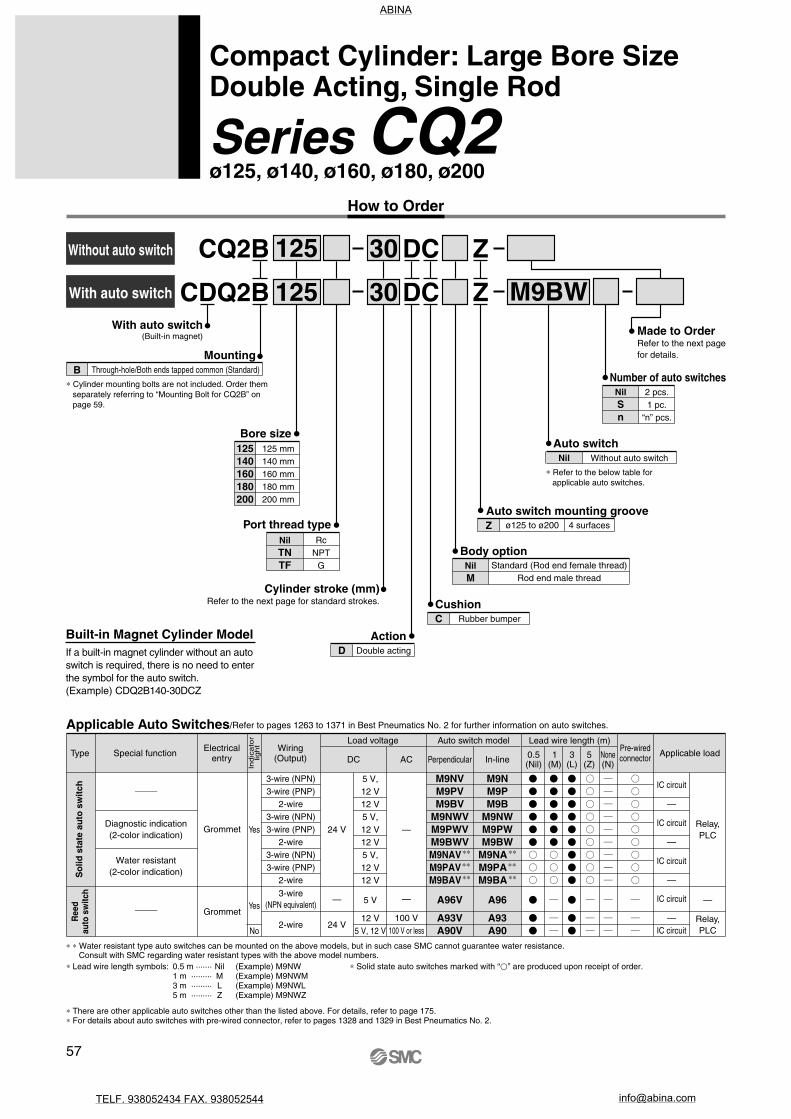
CQ2B
With auto switch
Without auto switch
CDQ2B
Cylinder stroke (mm)Refer to the next page for standard strokes.
Bore size125140160180200
125 mm140 mm160 mm180 mm200 mm
125
125 30
M9BW30
DC
DC
Action
Z
Z
Auto switch mounting grooveZ ø125 to ø200 4 surfaces
Applicable Auto Switches/Refer to pages 1263 to 1371 in Best Pneumatics No. 2 for further information on auto switches.
∗ ∗ Water resistant type auto switches can be mounted on the above models, but in such case SMC cannot guarantee water resistance. Consult with SMC regarding water resistant types with the above model numbers.
Built-in Magnet Cylinder ModelIf a built-in magnet cylinder without an auto switch is required, there is no need to enter the symbol for the auto switch.(Example) CDQ2B140-30DCZ
RcNPT
G
Port thread typeNilTNTF
Made to Order Refer to the next page for details.
YesGrommet
3-wire (NPN)3-wire (PNP)
2-wire3-wire (NPN)3-wire (PNP)
2-wire3-wire (NPN)3-wire (PNP)
2-wire
24 VRelay,PLC
—
—
5 V,12 V12 V5 V,12 V12 V5 V,12 V12 V
IC circuit
—
IC circuit
—
IC circuit
—
M9NVM9PVM9BV
M9NWVM9PWVM9BWVM9NAV
∗∗
M9PAV ∗∗
M9BAV ∗∗
M9NM9PM9B
M9NWM9PWM9BW
M9NA ∗∗
M9PA ∗∗
M9BA ∗∗
No
YesGrommet
3-wire(NPN equivalent)
2-wire 24 V
—
Relay,PLC
—
100 V100 V or less
5 V
12 V5 V, 12 V
IC circuit
—IC circuit
A96V
A93VA90V
A96
A93A90
How to Order
Compact Cylinder: Large Bore SizeDouble Acting, Single Rod
Series CQ2ø125, ø140, ø160, ø180, ø200
With auto switch(Built-in magnet)
BMounting
Through-hole/Both ends tapped common (Standard)
∗ Cylinder mounting bolts are not included. Order them separately referring to “Mounting Bolt for CQ2B” on page 59.
Number of auto switchesNilSn
2 pcs.1 pc.
“n” pcs.
Auto switchNil
∗ Refer to the below table for applicable auto switches.
Without auto switch
Body optionNilM
Standard (Rod end female thread)Rod end male thread
CushionC Rubber bumper
D Double acting
Type Special function Electricalentry
Wiring(Output)
Load voltage
DC AC
Lead wire length (m)
0.5(Nil)
3(L)
5(Z)
None(N)
Applicable loadPre-wiredconnector1
(M)
Auto switch model
Ind
ica
tor
ligh
t
Perpendicular In-line
Ree
dau
to s
witc
hS
olid
sta
te a
uto
sw
itch
Diagnostic indication(2-color indication)
Water resistant(2-color indication)
∗ Lead wire length symbols: 0.5 m ······· Nil (Example) M9NW1 m ········· M (Example) M9NWM3 m ········· L (Example) M9NWL5 m ········· Z (Example) M9NWZ
∗ Solid state auto switches marked with “” are produced upon receipt of order.
∗ There are other applicable auto switches other than the listed above. For details, refer to page 175.∗ For details about auto switches with pre-wired connector, refer to pages 1328 and 1329 in Best Pneumatics No. 2.
57
ABINA
TELF. 938052434 FAX. 938052544 [email protected]

JIS SymbolDouble acting, Single rod
Made to Order(For details, refer to pages 177 to 207.)
-XB10-X271
Intermediate stroke (Exclusive body type)
Fluororubber seals, ø125 to ø160 only
Symbol Specifications
Specifications
Action
Fluid
Proof pressure
Maximum operating pressure
Minimum operating pressure
Ambient and fluid temperature
Lubrication
Piston speed
Allowable kinetic energy (J)
Stroke length tolerance
Bore size (mm) 125 140 160 180 200
Note) Stroke length tolerance does not include the amount of bumper change.
7.4 9.8 12.4
Double acting, Single rod
Air
0.05 MPa
Not required (Non-lube)
1.5 MPa
1.0 MPa
1.05 MPa
0.7 MPa
50 to 500 mm/s 20 to 400 mm/s
Without auto switch: –10 to 70°C (No freezing)With auto switch: –10 to 60°C (No freezing)
+1.4 mm0
Note)
Bore size (mm)
125, 140, 160180, 200
Standard stroke
10, 20, 30, 40, 50, 75, 100, 125, 150, 175, 200, 250, 300
(mm)
Standard Strokes
Type
Part no.Refer to “How to Order” for the standard model number. (P. 57)
Part no.: CQ2B160-165DCZCQ2B160-175DCZ with 10 mm width spacer insideThe B dimension is 266 mm.
Part no.: CQ2B160-165DCZ-XB10Makes 165 mm stroke tube.The B dimension is 256 mm.
Strokes in 5 mm intervals are available by installing a spacer in the standard stroke cylinder.
Strokes in 1 mm intervals areavailable by using an exclusive body with the specified stroke.
Suffix “-XB10” to the end of standard model number. (P. 57)
Description
Stroke rangeBore size
125 to 200
Stroke range
5 to 295
Bore size
125 to 160
Stroke range
11 to 299
Example
A spacer is installed in the standard stroke body. Exclusive body (-XB10)
Manufacture of Intermediate Strokes
• Auto switch proper mounting position (detection at stroke end) and its mounting height• Minimum stroke for auto switch mounting• Operating range• Auto switch mounting brackets/Part no.
Refer to pages 169 to 175 for the specifications of cylinders with auto switches.
Sta
nd
ard
Lar
ge
Bo
reS
ize
Lo
ng
Str
oke
No
n-r
ota
tin
gR
od
Axi
al P
ipin
gA
nti
-lat
eral
Lo
adW
ith
En
d L
ock
Wat
erR
esis
tan
tA
uto
Sw
itch
Mad
e to
Ord
erW
ith
Au
toS
wit
ch
58
Series CQ2Compact Cylinder: Large Bore SizeDouble Acting, Single Rod
ABINA
TELF. 938052434 FAX. 938052544 [email protected]

OUT IN
125
140
160
180
200
IN
OUT
IN
OUT
IN
OUT
IN
OUT
IN
OUT
0.3
3376
3682
4313
4618
5655
6032
7257
7634
9048
9425
0.5
5627
6136
7188
7697
9425
10053
12095
12724
15080
15708
0.7
7878
8590
10063
10776
13195
14074
16933
17813
21112
21991
125140160180200
125140160180200
10
5.24
6.19
8.57
11.54
14.56
20
5.48
6.44
8.88
11.92
15.07
30
5.71
6.71
9.20
12.31
15.49
40
5.94
6.98
9.52
12.70
15.92
50
6.18
7.25
9.84
13.09
16.34
75
6.76
7.90
10.64
14.05
17.41
100
7.35
8.57
11.44
15.03
18.47
125
7.93
9.23
12.25
16.00
19.54
150
8.52
9.90
13.05
16.97
20.60
175
9.10
10.56
13.85
17.93
21.67
200
9.69
11.23
14.65
18.90
22.82
250
10.86
12.55
16.26
20.84
24.85
300
12.03
13.88
17.85
22.78
26.99
10
5.30
6.26
8.65
11.62
14.64
20
5.54
6.51
8.96
12.00
15.15
30
5.77
6.78
9.28
12.39
15.57
40
6.01
7.05
9.60
12.78
16.00
50
6.24
7.32
9.92
13.17
16.42
75
6.83
7.97
10.72
14.13
17.49
100
7.40
8.64
11.52
15.11
18.55
125
7.99
9.30
12.33
16.08
19.62
150
8.58
9.97
13.13
17.05
20.68
175
9.16
10.63
13.93
18.01
21.75
200
9.75
11.30
14.73
18.98
22.90
250
10.92
12.62
16.34
20.92
24.93
300
12.09
13.95
17.93
22.86
27.07
COAD
Cylinder model C D
22.9
100110120130140165190110120130140150175200
CQ-M12 x 100L x 110L x 120L x 130L x 140L x 165L x 190L
CQ-M14 x 110L x 120L x 130L x 140L x 150L x 175L x 200L
27.7
Mounting bolt part no.
CQ2B125/140-10DCZ -20DCZ -30DCZ -40DCZ -50DCZ -75DCZ -100DCZ
CQ2B160-10DCZ -20DCZ -30DCZ -40DCZ -50DCZ -75DCZ -100DCZ
Cylinder model C D
36
125135145155165190215135145155165175200225
CQ-M18 x 125L x 135L x 145L x 155L x 165L x 190L x 215L
CQ-M18 x 135L x 145L x 155L x 165L x 175L x 200L x 225L
39
Mounting bolt part no.
CQ2B180-10DCZ -20DCZ -30DCZ -40DCZ -50DCZ -75DCZ -100DCZ
CQ2B200-10DCZ -20DCZ -30DCZ -40DCZ -50DCZ -75DCZ -100DCZ
Theoretical Output
(N)
Bore size(mm) Operating direction
Operating pressure (MPa)
Without Auto Switch (kg)
With Auto Switch (kg)
Bore size(mm)
Bore size(mm)
Cylinder stroke (mm)
Cylinder stroke (mm)
Weight
Calculation: (Example) CDQ2B125-30DCMZ• Basic weight: CDQ2B125-30DCZ······ 5.77 kg• Additional weight: Rod end male thread··· 0.47 kg
6.24 kg
Additional Weight (kg)
Bore size (mm)
Rod endmale thread
Male thread
Nut
0.31
0.16
125
0.31
0.16
140
0.48
0.26
160180200
Mounting Bolt for CQ2BMounting method: Mounting bolt for through-hole mounting of the CQ2B is available as an option. Refer to the following for ordering procedures. Order the actual number of bolts that will be used.
Example) CQ-M12x100L 4 pcs.
Note 1) To install a through-hole type mounting bolt, make sure to use the flat washer that is provided.
Note 2) For mounting bolts for the stroke length exceeding 100 mm, use the OA screw provided on the cylinder tube to secure the cylinder.
Material: Chromium molybdenum steelSurface treatment: Nickel plated
59
Series CQ2
ABINA
TELF. 938052434 FAX. 938052544 [email protected]
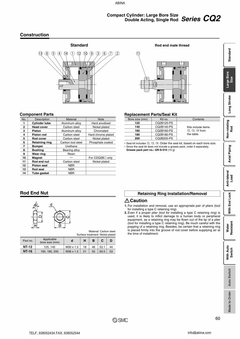
NT-12NT-16
125, 140
160, 180, 200
18
21
46
55
44
53
53.1
63.5
M30 x 1.5
M36 x 1.5
d H B C D
Retaining Ring Installation/Removal
Caution1. For installation and removal, use an appropriate pair of pliers (tool
for installing a type C retaining ring).2. Even if a proper plier (tool for installing a type C retaining ring) is
used, it is likely to inflict damage to a human body or peripheral equipment, as a retaining ring may be flown out of the tip of a plier (tool for installing a type C retaining ring). Be much careful with the popping of a retaining ring. Besides, be certain that a retaining ring is placed firmly into the groove of rod cover before supplying air at the time of installment.
Standard Rod end male thread
Construction
Component PartsNo.1234567891011121314
DescriptionCylinder tubeHead coverPistonPiston rodRod coverRetaining ringBumperBushingWear ringMagnetRod end nutPiston sealRod sealTube gasket
MaterialAluminum alloyCarbon steel
Aluminum alloyCarbon steelCarbon steel
Carbon tool steelUrethane
Bearing alloyResin
—
Carbon steelNBRNBRNBR
NoteHard anodizedNickel platedChromated
Hard chrome platedNickel plated
Phosphate coated
For CDQ2B only Nickel plated
CQ2B125-PSCQ2B140-PSCQ2B160-PSCQ2B180-PSCQ2B200-PS
Replacement Parts/Seal Kit
125140160180200
Bore size (mm) Kit no. Contents
∗ Seal kit includes !2, !3, !4. Order the seal kit, based on each bore size.∗ Since the seal kit does not include a grease pack, order it separately. Grease pack part no.: GR-S-010 (10 g)
Rod End Nut
Part no. Applicablebore size (mm)
Material: Carbon steelSurface treatment: Nickel plated
Kits include items!2, !3, !4 fromthe table.
Sta
nd
ard
Lar
ge
Bo
reS
ize
Lo
ng
Str
oke
No
n-r
ota
tin
gR
od
Axi
al P
ipin
gA
nti
-lat
eral
Lo
adW
ith
En
d L
ock
Wat
erR
esis
tan
tA
uto
Sw
itch
Wit
h A
uto
Sw
itch
Mad
e to
Ord
er
60
Series CQ2Compact Cylinder: Large Bore SizeDouble Acting, Single Rod
ABINA
TELF. 938052434 FAX. 938052544 [email protected]
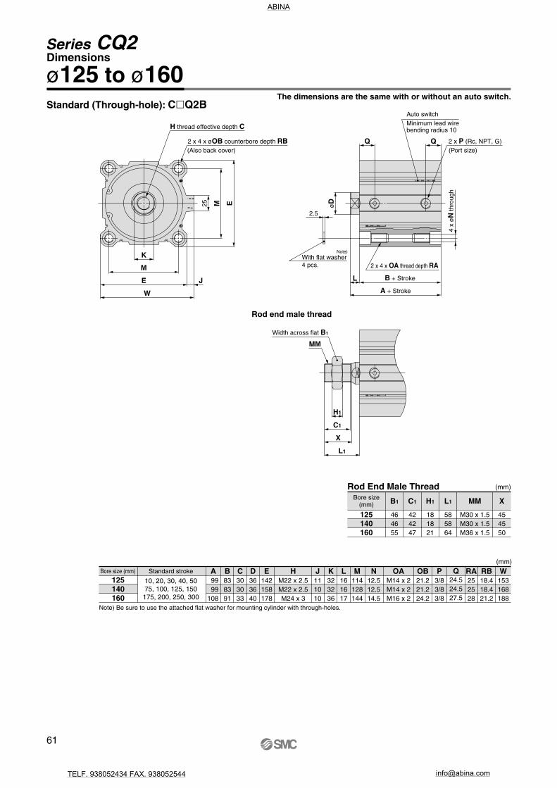
Width across flat B1
4 x
øN
thro
ugh
B + Stroke
A + Stroke
Auto switchMinimum lead wirebending radius 10
Note)
2 x 4 x OA thread depth RAWith flat washer4 pcs.
2 x P (Rc, NPT, G)(Port size)
H thread effective depth C
2 x 4 x øOB counterbore depth RB(Also back cover)
(mm)
125140160
B1 C1 MML1 X
464655
424247
H1
181821
M30 x 1.5M30 x 1.5M36 x 1.5
585864
454550
125140160
10, 20, 30, 40, 5075, 100, 125, 150
175, 200, 250, 300
99 99108
B838391
C303033
D363640
E142158178
HM22 x 2.5M22 x 2.5M24 x 3
J111010
K323236
L161617
M114128144
N12.512.514.5
OAM14 x 2M14 x 2M16 x 2
OB21.221.224.2
P3/83/83/8
Q24.524.527.5
RA252528
RB18.418.421.2
W153168188
(mm)
MM
L
2.5
øD
Q
L1
X
C1
H1
K
M
E J
M E
W
25
Q
A
Standard (Through-hole): CQ2BThe dimensions are the same with or without an auto switch.
ø125 to ø160Dimensions
Rod end male thread
Rod End Male ThreadBore size
(mm)
Bore size (mm) Standard stroke
Note) Be sure to use the attached flat washer for mounting cylinder with through-holes.
61
Series CQ2
ABINA
TELF. 938052434 FAX. 938052544 [email protected]

M24 x 3 thread effective depth 33
2 x 4 x ø31.5 counterbore depth 26(Also back cover)
Width across flat 55
119 + Stroke
102 + Stroke
4 x
ø19
thro
ugh
Minimum lead wire bending radius 10Auto switch
2 x 4 x M22 x 2.5thread depth 38 Note 1)4 pcs.
With flat washer Note 2)
(Port size)
2 x Rc, NPT, G 1/2
2 x 4 x M22 x 2.5thread depth 38 Note 1)
4 x
ø19
thro
ugh
109 + Stroke
126 + Stroke
Minimum lead wire bending radius 10Auto switch
4 pcs.With flat washer Note 2)
(Port size)
2 x Rc, NPT, G 1/2
Width across flat 55
M24 x 3 thread effective depth 33
(Also back cover)2 x 4 x ø31.5 counterbore depth 26
ø200
M36 x 1.5
36
3
17
ø40
182
226
182
226
3030
6262
64
50
47
21
3.6
M36 x 1.5
29 29
5252
3
ø40
64
50
47
21
17
162
204
36
162
204
1.5
Note 1) In the case of 20 mm stroke or less, it would come with 2 x 4 x M22 x 2.5 through thread.
Note 2) Be sure to use the attached flat washer for mounting cylinder with through-holes.
Note 1) In the case of 20 mm stroke or less, it would come with 2 x 4 x M22 x 2.5 through thread.
Note 2) Be sure to use the attached flat washer for mounting cylinder with through-holes.
Dimensions
ø180 The dimensions are the same with or without an auto switch.
ø180, ø200
Sta
nd
ard
Lar
ge
Bo
reS
ize
Lo
ng
Str
oke
No
n-r
ota
tin
gR
od
Axi
al P
ipin
gA
nti
-lat
eral
Lo
adW
ith
En
d L
ock
Wat
erR
esis
tan
tA
uto
Sw
itch
Mad
e to
Ord
erW
ith
Au
toS
wit
ch
62
Series CQ2Compact Cylinder: Large Bore SizeDouble Acting, Single Rod
ABINA
TELF. 938052434 FAX. 938052544 [email protected]

CQ2WB
Bore size125140160180200
125 mm140 mm160 mm180 mm200 mm
125
125 30
30
DC
Applicable Auto Switches/Refer to pages 1263 to 1371 in Best Pneumatics No. 2 for further information on auto switches.
CDQ2WB DC
Z
Z M9BW
RcNPT
G
Port thread typeNilTNTF
Made to OrderRefer to the next page for details.
—
M9NVM9PVM9BV
M9NWVM9PWVM9BWVM9NAV
∗∗
M9PAV ∗∗
M9BAV ∗∗
M9NM9PM9B
M9NWM9PWM9BW
M9NA ∗∗
M9PA ∗∗
M9BA ∗∗
—
—— A96V
A93VA90V
A96
A93A90
How to Order
Compact Cylinder: Large Bore SizeDouble Acting, Double Rod
Series CQ2Wø125, ø140, ø160, ø180, ø200
With auto switch(Built-in magnet)
TypeW Double rod
MountingB Through-hole/Both ends tapped common (Standard)
∗ Cylinder mounting bolts are not included. Order them separately referring to “Mounting Bolt for CQ2WB” on page 66.
Cylinder stroke (mm)Refer to the next page
for standard strokes.
Built-in Magnet Cylinder ModelIf a built-in magnet cylinder without an auto switch is required, there is no need to enter the symbol for the auto switch.(Example) CDQ2WB140-30DCZ
Number of auto switchesNilSn
2 pcs.1 pc.
“n” pcs.
Auto switchNil Without auto switch
∗ Refer to the below table for applicable auto switches.
Auto switch mounting grooveZ ø125 to ø200 4 surfaces
Body optionNilM
Standard (Rod end female thread)Rod end male thread
CushionC Rubber bumper
ActionD Double acting
Type Special function Electricalentry
Wiring(Output)
Load voltage
DC AC
Lead wire length (m)
0.5(Nil)
3(L)
5(Z)
None(N)
Applicable loadPre-wiredconnector1
(M)
Auto switch model
Ind
ica
tor
ligh
t
Perpendicular In-line
YesGrommet
3-wire (NPN)3-wire (PNP)
2-wire3-wire (NPN)3-wire (PNP)
2-wire3-wire (NPN)3-wire (PNP)
2-wire
No
YesGrommet
3-wire(NPN equivalent)
2-wire
Ree
dau
to s
witc
hS
olid
sta
te a
uto
sw
itch
Diagnostic indication(2-color indication)
Water resistant(2-color indication)
24 V
5 V,12 V12 V5 V,12 V12 V5 V,12 V12 V
24 V
5 V
12 V5 V, 12 V
—
100 V100 V or less
∗ ∗ Water resistant type auto switches can be mounted on the above models, but in such case SMC cannot guarantee water resistance. Consult with SMC regarding water resistant types with the above model numbers.
∗ Lead wire length symbols: 0.5 m ······· Nil (Example) M9NW1 m ········· M (Example) M9NWM3 m ········· L (Example) M9NWL5 m ········· Z (Example) M9NWZ
∗ Solid state auto switches marked with “” are produced upon receipt of order.
∗ There are other applicable auto switches other than the listed above. For details, refer to page 175.∗ For details about auto switches with pre-wired connector, refer to pages 1328 and 1329 in Best Pneumatics No. 2.
Relay,PLC
IC circuit
—
IC circuit
—
IC circuit
—
Relay,PLC
—IC circuit
—IC circuit
With auto switch
Without auto switch
63
ABINA
TELF. 938052434 FAX. 938052544 [email protected]

-XB10-X235-X271
-X633
Intermediate stroke (Exclusive body type)
Special rod end for double rod cylinder
Fluororubber seals, ø125 to ø160 only
Intermediate stroke of double rod cylinder,ø125 to ø160 only
Symbol Specifications
∗ -X633: Intermediate stroke in 5 mm intervals only
• Auto switch proper mounting position (detection at stroke end) and its mounting height• Minimum stroke for auto switch mounting• Operating range• Auto switch mounting brackets/Part no.
Refer to pages 169 to 175 for the specifications of cylinders with auto switches.
Made to Order(For details, refer to pages 177 to 207.)
JIS SymbolDouble acting, Double rod
Action
Fluid
Proof pressure
Maximum operating pressure
Minimum operating pressure
Ambient and fluid temperature
Lubrication
Piston speed
Allowable kinetic energy (J)
Stroke length tolerance
Bore size (mm) 125 140 160 180 200
Note) Stroke length tolerance does not include the amount of bumper change.
7.4 9.8 12.4
Double acting, Double rod
Air
0.05 MPa
Not required (Non-lube)
1.5 MPa
1.0 MPa
1.05 MPa
0.7 MPa
50 to 500 mm/s 20 to 400 mm/s
Without auto switch: –10 to 70°C (No freezing)With auto switch: –10 to 60°C (No freezing)
+1.4 mm0
Note)
Specifications
Bore size (mm)
125, 140, 160180, 200
Standard stroke
10, 20, 30, 40, 50, 75, 100, 125, 150, 175, 200, 250, 300
(mm)
Standard Strokes
Type
Part no.Suffix “-X633” to the end of standard model number. (P. 63)
Part no.: CQ2WB160-165DCZ-X633CQ2WB160-175DCZ with 10 mm width spacer insideThe B dimension is 266 mm.
Part no.: CQ2WB160-165DCZ-XB10Makes 165 mm stroke tube.The B dimension is 256 mm.
Strokes in 5 mm intervals are available by installing a spacer inthe standard stroke cylinder.
Strokes in 1 mm intervals areavailable by using an exclusive body with the specified stroke.
Suffix “-XB10” to the end of standard model number. (P. 63)
Description
Stroke rangeBore size
125 to 160
Stroke range
5 to 295
Bore size
125 to 160
Stroke range
11 to 299
Example
A spacer is installed in the standard stroke body. Exclusive body (-XB10)
Manufacture of Intermediate Strokes
Sta
nd
ard
Lar
ge
Bo
reS
ize
Lo
ng
Str
oke
No
n-r
ota
tin
gR
od
Axi
al P
ipin
gA
nti
-lat
eral
Lo
adW
ith
En
d L
ock
Wat
erR
esis
tan
tA
uto
Sw
itch
Mad
e to
Ord
erW
ith
Au
toS
wit
ch
64
Series CQ2WCompact Cylinder: Large Bore SizeDouble Acting, Double Rod
ABINA
TELF. 938052434 FAX. 938052544 [email protected]

125140160180200
0.3
3376
4313
5655
7257
9048
0.5
5627
7188
9425
12095
15080
0.7
7878
10063
13195
16933
21112
125140160180200
10
5.47
6.43
8.87
11.75
14.89
20
5.76
6.73
9.26
12.23
15.42
30
6.05
7.06
9.65
12.73
15.94
40
6.37
7.40
10.07
13.21
16.47
50
6.68
7.75
10.49
13.70
16.98
75
7.47
8.61
11.53
14.91
18.30
100
8.24
9.47
12.58
16.13
19.61
125
9.03
10.33
13.63
17.34
20.92
150
9.82
11.20
14.68
18.56
21.23
175
10.60
12.06
15.72
19.77
23.54
200
11.39
12.92
16.77
20.99
24.85
250
12.96
14.64
18.87
23.42
27.47
300
14.52
16.37
20.96
25.86
30.10
125140160180200
10
5.53
6.50
8.95
11.83
14.97
20
5.82
6.80
9.34
12.31
15.50
30
6.11
7.13
9.73
12.81
16.02
40
6.43
7.47
10.15
13.29
16.55
50
6.74
7.82
10.57
13.78
17.06
75
7.53
8.68
11.61
14.99
18.38
100
8.30
9.54
12.66
16.21
19.69
125
9.09
10.40
13.71
17.42
21.00
150
9.88
11.27
14.76
18.64
21.31
175
10.66
12.13
15.80
19.85
23.62
200
11.45
12.99
16.85
21.07
24.93
250
13.02
14.71
18.95
23.50
27.55
300
14.58
16.44
21.04
25.94
30.18
Caution1. For installation and removal, use an appropri-
ate pair of pliers (tool for installing a type C retaining ring).
2. Even if a proper plier (tool for installing a type C retaining ring) is used, it is likely to inflict damage to a human body or peripheral equipment, as a retaining ring may be flown out of the tip of a plier (tool for installing a type C retaining ring). Be much careful with the popping of a retaining ring. Besides, be certain that a retaining ring is placed firmly into the groove of rod cover before supplying air at the time of installment.
Retaining Ring Installation/Removal
Do not apply reverse torque to the piston rods sticking out from both sides of this cylinder at the same time. The torque makes connection threads inside loosen, which may cause an accident or malfunction. Install or remove loads while the piston rod width across flat is secured. Do not fix the other side of the piston rod width across flat and apply reverse torque.
Mounting
Warning
Operating pressure (MPa)Bore size(mm)
(N)
Theoretical Output
Weight
Without Auto SwitchBore size
(mm)
Cylinder stroke (mm)
(kg)
With Auto SwitchCylinder stroke (mm)
(kg)
Bore size(mm)
Additional Weight (kg)
Bore size (mm)
Rod end male threadMale thread
Nut
1250.62
0.32
1400.62
0.32
160, 180, 2000.96
0.52
Calculation: (Example) CDQ2WB125-30DCMZ• Basic weight: CDQ2WB125-30DCZ ····6.11 kg• Additional weight: Rod end male thread ·····0.94 kg
7.05 kg
65
Series CQ2W
ABINA
TELF. 938052434 FAX. 938052544 [email protected]

NT-12NT-16
125, 140
160, 180, 200
18
21
46
55
44
53
53.1
63.5
M30 x 1.5
M36 x 1.5
d H B C D
Cylinder model C D
22.9
100110120130140165190110120130140150175200
CQ-M12 x 100L x 110L x 120L x 130L x 140L x 165L x 190L
CQ-M14 x 110L x 120L x 130L x 140L x 150L x 175L x 200L
27.7
Mounting bolt part no.
Mounting method: Mounting bolt for through-hole mounting of the CQ2WB is available as an option.Refer to the following for ordering procedures. Order the actual number of bolts that will be used.
CQ2WB125/140-10DCZ -20DCZ -30DCZ -40DCZ -50DCZ -75DCZ -100DCZ
CQ2WB160-10DCZ -20DCZ -30DCZ -40DCZ -50DCZ -75DCZ -100DCZ
Cylinder model C D
36
125135145155165190215135145155165175200225
CQ-M18 x 125L x 135L x 145L x 155L x 165L x 190L x 215L
CQ-M18 x 135L x 145L x 155L x 165L x 175L x 200L x 225L
39
Mounting bolt part no.CQ2WB180-10DCZ
-20DCZ -30DCZ -40DCZ -50DCZ -75DCZ -100DCZ
CQ2WB200-10DCZ -20DCZ -30DCZ -40DCZ -50DCZ -75DCZ -100DCZ
125140160180200
CQ2WB125-PSCQ2WB140-PSCQ2WB160-PSCQ2WB180-PSCQ2WB200-PS
Replacement Parts/Seal KitBore size (mm) Kit no. Contents
∗ Seal kit includes !1, !2, !3. Order the seal kit, based on each bore size.∗ Since the seal kit does not include a grease pack, order it separately. Grease pack part no.: GR-S-010 (10 g)
Example) CQ-M12x100L 4 pcs.
Mounting Bolt for CQ2WB
Note 1) To install a through-hole type mounting bolt, make sure to use the flat washer that is provided.
Note 2) For mounting bolts for the stroke length exceeding 100 mm, use the OA screw provided on the cylinder tube to secure the cylinder.
Material: Chromium molybdenum steelSurface treatment: Nickel plated
OA thread part Mounting bolt
Rod end male threadStandard
Construction
Hard anodizedChromated
Hard chrome platedHard chrome plated
Nickel platedPhosphate coated
For CDQ2WB onlyNickel plated
Component PartsNo.1234567891011121314
DescriptionCylinder tubePistonPiston rod APiston rod BRod coverRetaining ringBumperBushingMagnetRod end nutPiston sealRod sealTube gasketPiston gasket
MaterialAluminum alloyAluminum alloyCarbon steelCarbon steelCarbon steel
Carbon tool steelResin
Bearing alloy—
Carbon steelNBRNBRNBRNBR
Note
Rod End Nut
Material: Carbon steelSurface treatment: Nickel plated
Part no. Applicablebore size (mm)
Kits include items!1, !2, !3 fromthe table.
Sta
nd
ard
Lar
ge
Bo
reS
ize
Lo
ng
Str
oke
No
n-r
ota
tin
gR
od
Axi
al P
ipin
gA
nti
-lat
eral
Lo
adW
ith
En
d L
ock
Wat
erR
esis
tan
tA
uto
Sw
itch
Wit
h A
uto
Sw
itch
Mad
e to
Ord
er
66
Series CQ2WCompact Cylinder: Large Bore SizeDouble Acting, Double Rod
ABINA
TELF. 938052434 FAX. 938052544 [email protected]

L1 + Stroke
A1 + 2 (Stroke)
(Also back cover)
(Also back cover)
2 x 4 x øOB counterbore depth RB
2 x H thread effective depth C
4 x
øN
thro
ugh-
hole
B + Stroke
A + 2 (Stroke)
L + Stroke
Minimum lead wire bending radius 10
Auto switch
Width across flat K
2 x 4 x OAthread depth RA
4 pcs.With flat washer Note 1)
(Port size)2 x P (Rc, NPT, G)
(mm)
125140160
199199219
464655
585864
454550
A1 B1
M30 x 1.5M30 x 1.5M36 x 1.5
MML1
424247
181821
C1 H1 X
(mm)
125140160
HM22 x 2.5M22 x 2.5M24 x 3
OAM14 x 2M14 x 2M16 x 2
C30 (22.5)30 (22.5)33 (26.5)
A115115125
E142158178
10, 20, 30, 40, 5075, 100, 125, 150175, 200, 250, 300
B838391
D363640
J111010
K323236
L161617
M114128144
N12.512.514.5
OB21.221.224.2
Q24.524.527.5
P3/83/83/8
RA252528
RB18.418.421.2
W153168188
MMMM
B1 B1
2.5
L
Q Q
øD
øD
L1
X
C1
X
C1
H1 H1
K
M
E J
M E
W
25
Dimensions
Standard (Through-hole): CQ2WBThe dimensions are the same with or without an auto switch.
ø125 to ø160
Rod end male thread
Rod End Male ThreadBore size
(mm)
Note 1) Be sure to use the attached flat washer for mounting cylinder with through-holes.Note 2) ( ): Values of effective length in one side, only for 10 mm stroke model∗ The positions of double rod width across flats are not the same.
Bore size (mm) Standard stroke Note 2)
67
Series CQ2W
ABINA
TELF. 938052434 FAX. 938052544 [email protected]

230 + 2 (Stroke)
64 + Stroke
Width across flat 55Width across flat 55
136 + 2 (Stroke)
17 + Stroke102 + Stroke
4 x
ø19
thro
ugh
Minimum lead wire bending radius 10Auto switch
2 x 4 x M22 x 2.5thread depth 38 Note 1)
4 pcs.With flat washer Note 2)
(Port size)2 x Rc, NPT, G 1/2
2 x M24 x 3 effective thread depth 33
2 x 4 x ø31.5 counterbore depth 26
237 + 2 (Stroke)
64 + Stroke
Width across flat 55Width across flat 55
(Also back cover)2 x M24 x 3 effective thread depth 33
(Also back cover)2 x 4 x ø31.5 counterbore depth 26
143 + 2 (Stroke)
17 + Stroke
4 x
ø19
thro
ugh
109 + Stroke
Width across flat 36
Minimum lead wire bending radius 10Auto switch
4 pcs.With flat washer Note 2)
(Port size)2 x Rc, NPT, G 1/2
2 x 4 x M22 x 2.5thread depth 38 Note 1)
(Also back cover)
(Also back cover)
ø200
M36 x 1.5 M36 x 1.5
29 29
523
ø40
64
50
47
21
ø40
52
17
50
47
21
162
204
36
162
204
1.5
M36 x 1.5 M36 x 1.5
3
17
ø40
3030
6262
64
50
47
21
ø40
30
50
47
21
36
182
226
182
226
3.6
Dimensions
ø180
ø180, ø200The dimensions are the same with or without an auto switch.
∗ The positions of double rod width across flats are not the same.
Note 1) In the case of 20 mm stroke or less, it would come with 2 x 4 x M22 x 2.5 through thread.
Note 2) Be sure to use the attached flat washer for mounting cylinder with through-holes.
Note 1) In the case of 20 mm stroke or less, it would come with 2 x 4 x M22 x 2.5 through thread.
Note 2) Be sure to use the attached flat washer for mounting cylinder with through-holes.
Sta
nd
ard
Lar
ge
Bo
reS
ize
Lo
ng
Str
oke
No
n-r
ota
tin
gR
od
Axi
al P
ipin
gA
nti
-lat
eral
Lo
adW
ith
En
d L
ock
Wat
erR
esis
tan
tA
uto
Sw
itch
Mad
e to
Ord
erW
ith
Au
toS
wit
ch
68
Series CQ2WCompact Cylinder: Large Bore SizeDouble Acting, Double Rod
ABINA
TELF. 938052434 FAX. 938052544 [email protected]