cpm drainage32w36r5zjfk38q89v1fnrs4t.wpengine.netdna-cdn.com/.../cpm-drainage... · cpm is a...
TRANSCRIPT

CPM Drainage
Concrete for Life
PipesManholesCaissonsGully PotsBox Culverts
Drainage

CPM is a market-leading manufacturer of precast concrete products with extensive production facilities across the UK. This combined with a network of specialist distributors, enables us to provide our customers with complete UK coverage.
The CPM business is built on a solid reputation for delivering quality products and providing a first class service with diversification and innovation a key to our strength. We supply a vast range of sustainable precast concrete products to every sector of the construction industry, fully supported by our experienced technical and engineering teams.
CPM – Concrete for Life
CPM drainage products are designed and manufactured to British/European Standards and/or other customer requirements, and are kitemarked and CE Marked where applicable (only products covered by Harmonised Standards can be CE Marked). Our objectives are not only to continue to meet these requirements, but also to provide a high standard of service in a professional manner, to supply products that are competitively priced, to work with customers, suppliers and designers on developing our product range, to develop user loyalty and so achieve strong business performance.
To meet our objectives, the company applies a quality management system which has been developed in accordance with the requirements of ISO 9001 certification.
CPM – Build on our strength
The CPM team of engineers and technicians are at the forefront of precast concrete technology with BIM (Building Information Modeling), AutoCAD drawings, designs, calculations and installation advice being just some of the benefits we provide and all our design work is fully supported by professional indemnity insurance for peace of mind.
Quality and Accreditation
02-03
Welcome to CPM
CPM Group Ltd CPM Group LtdCPM Group LtdCPM Group Ltd CPM Group Ltd
Please note that all weights and dimensions are approximate and subject to change. A copy of CPM’s terms and conditions is available at www.cpm-group.com
Box Culvert AssocationMembership by Milton Precast
Concrete for Life02-03
+ Product Index
Welcome to CPM Group / Product Index
Flexible Jointed Pipes
Rocker Pipes / Butt Pipes / Uni Junctions / Ovoid Pipes
Tumbling Bay / Drawings
Pipe Handling / Pipe Jointing
Tradtional Manholes / Soakaway Chambers / Special Cover Slabs
Caissons / Adjusting Units
House Inspection Chambers
Pipe Jointing / Air Testing
Gully Pots
The Perfect Manhole System
Integrated Ladder System / Catch-pit / Silt Chamber Systems
Preformed Manholes / L Shape Retaining Walls
Box Culverts
02-03
04-05
06-07
08-09
10-11
12-13
14-17
18-19
20-23
24-25
26-35
36-39
40-41
42-43
04-05
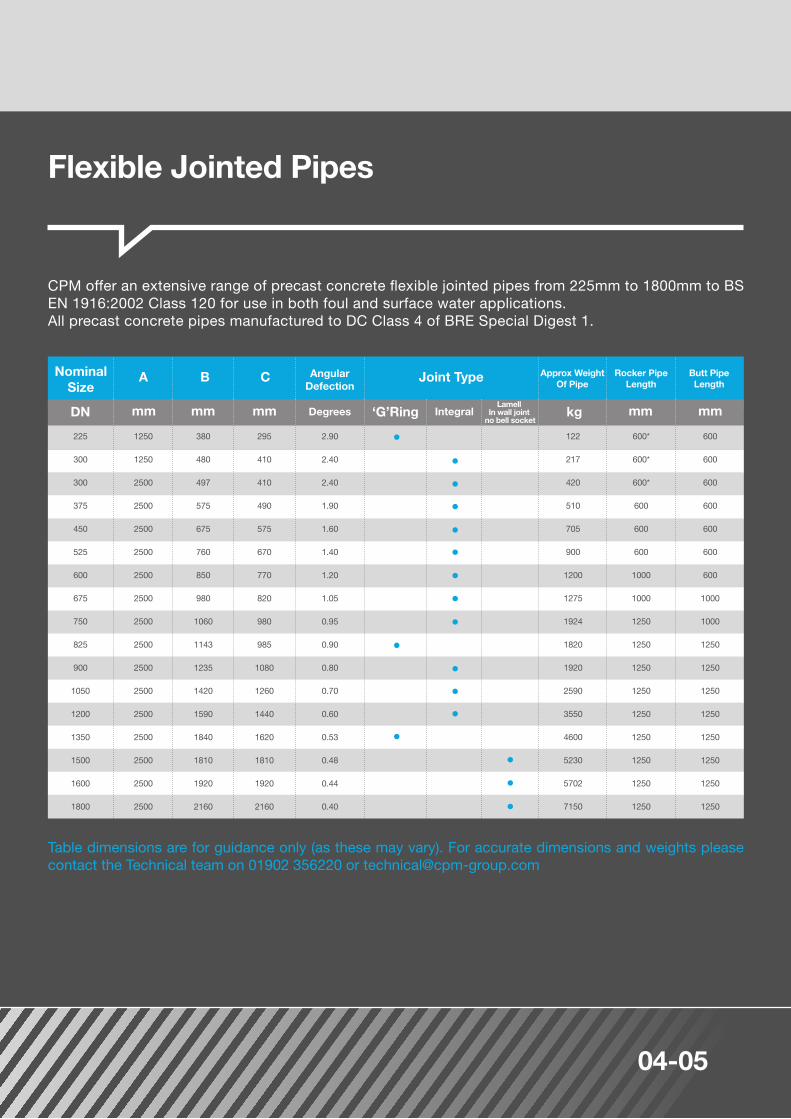
CPM offer an extensive range of precast concrete flexible jointed pipes from 225mm to 1800mm to BS EN 1916:2002 Class 120 for use in both foul and surface water applications. All precast concrete pipes manufactured to DC Class 4 of BRE Special Digest 1.
NominalSize
122
217
420
510
705
900
1200
1275
1924
1820
1920
2590
3550
4600
5230
5702
7150
600*
600*
600*
600
600
600
1000
1000
1250
1250
1250
1250
1250
1250
1250
1250
1250
600
600
600
600
600
600
600
1000
1000
1250
1250
1250
1250
1250
1250
1250
1250
225
300
300
375
450
525
600
675
750
825
900
1050
1200
1350
1500
1600
1800
1250
1250
2500
2500
2500
2500
2500
2500
2500
2500
2500
2500
2500
2500
2500
2500
2500
380
480
497
575
675
760
850
980
1060
1143
1235
1420
1590
1840
1810
1920
2160
295
410
410
490
575
670
770
820
980
985
1080
1260
1440
1620
1810
1920
2160
2.90
2.40
2.40
1.90
1.60
1.40
1.20
1.05
0.95
0.90
0.80
0.70
0.60
0.53
0.48
0.44
0.40
Joint TypeA
‘G’Ringmm mmmm mmmmDN
B
kg
C Approx WeightOf Pipe
LamellIn wall joint
no bell socket
Rocker Pipe Length
Butt PipeLength
Table dimensions are for guidance only (as these may vary). For accurate dimensions and weights please contact the Technical team on 01902 356220 or [email protected]
Flexible Jointed Pipes
AngularDefection
Degrees Integral

Concrete for Life04-05
Perforated Pipes
CPM manufactures precast concrete perforated pipes up to 600mm diameter that transport and distribute storm water into the rock filled trench and eventually into the surrounding area through the circular perforations. Concrete perforated pipes are suitable for field drains or french drains.
Perforated pipes are no longer a British Standard product. The pipes are drilled whilst wet and the semi-dry nature of the concrete used in the manufacturing process leads to spalling on the inner and outer surfaces around the holes. This is cosmetic only and does not affect the integrity of the pipes for land drainage use.
Perforated pipes comply with the Department of Transport Specification for Highway Works, which states the total area of drainage holes should not be less than 1000mm2 per metre length of pipe.
Seals are normally SBR complying with BS EN 681-1:1996. Other compounds such as Nitrile or EPDM can be supplied but may not be available from stock.
Pipes supplied with an in wall joint - no bell socket (full flexibility at joint maintained).
CPM specialised Flexi-lift system for handling/jointing purposes for pipes DN1200 to DN1800 is available.
Lorries with crane off load facilities are available for pipes up to DN 600 upon request, although site assistance would be required on certain diameters.
When ordering pipes which may have to joint with pipes already on site or previously laid, particularly extensions to contracts, it is important to advise the sales office accordingly in order to eradicate any jointing problems.
CPM lubricant is advised for use on integral pipes, CPM cannot guarantee that the jointing of concrete pipes with the use of other lubricants will be successful.
Lifting and Handling DN225 - DN1050 Straps / Pipe lifter DN1200-DN1800 Flexi-lifting / jointing chains.
1.
2.
3
4.
5.
6.
7.
Notes:
For DN 225 up to DN 1350 For DN 1500 up to DN 1800 / In-wall joint

06-07
Butt pipes and rocker pipes allow for any differential settlement between the manhole and the pipeline, with the spigot/socket butt pipe being built into the manhole wall. A rocker pipe is then laid connecting the butt pipe to the incoming/outgoing pipe run, thereby incorporating a flexible joint close to the manhole.
Branches of 100mm upwards can be fitted into all pipe sizes. Branches can be made from drainage materials other than concrete and are normally fitted to both full and short length pipes to suit customer requirements.
Rocker Pipes / Butt Pipes
Junctions
Rocker Pipe Spigot Butts Socket Butts
NominalSize
NominalSize
EffectiveLength
EffectiveLength
225 - 600 225 - 600
675 - 750 675 - 750
825 and above 825 and above
600 600
1000 1000
1250 1250
mm mmDN DN
CPM uni-junctions are 150mm diameter connections to suit pipes from 300mm up to 1800mm. The uni-junction is an alternative to a fixed branch junction and offers the following advantages:
The uni junction is designed to suit 150mm supersleve clay pipes not slimline clay pipes. To connect to plastic pipes, an adaptor coupling from the clay to the plastic pipe will be required. Alternatively for certain plastic pipes an adaptor bush is available. Contact our Sales office for full compatibility details. For information on bends and tumbling bay junctions, please visit www.cpm-group.com
Uni Junctions
Quicker and easier installationLess susceptible to site and transport damage Allows for more flexibility when positioning the branch along the pipelineGreater flexibility being able to accommodate a range of pipe material using adaptorsAngular connections can be made using bends
Concrete for Life06-07
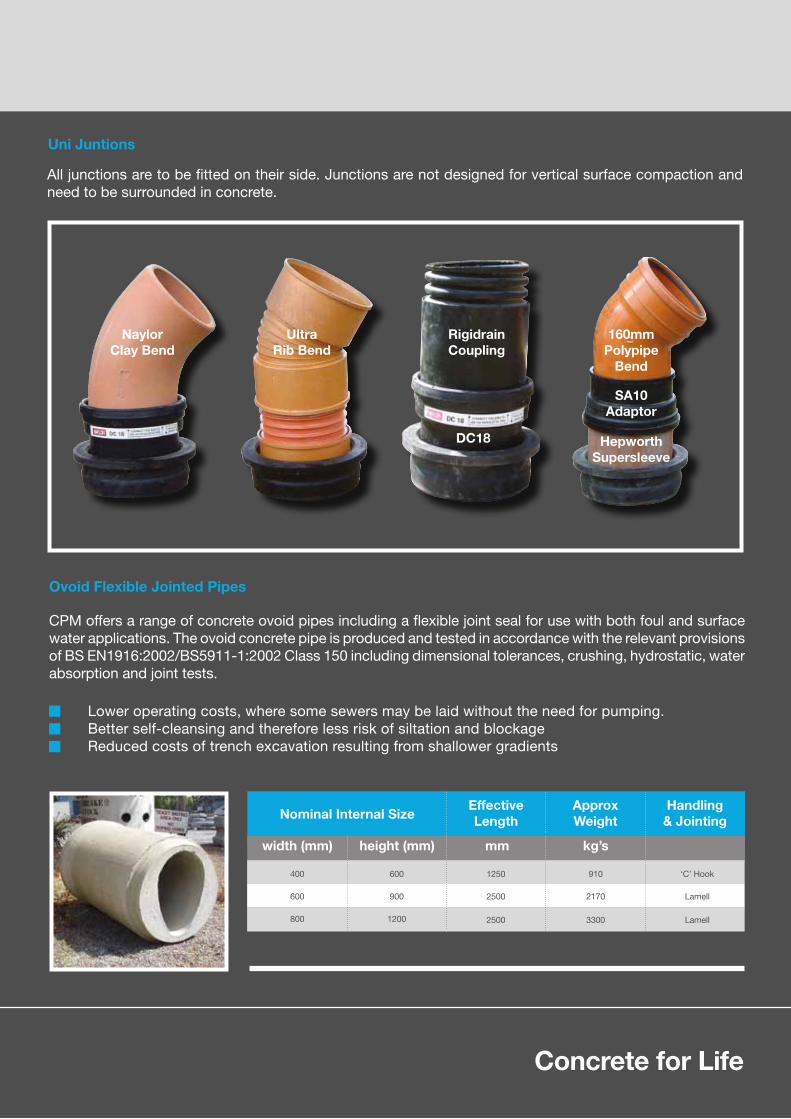
All junctions are to be fitted on their side. Junctions are not designed for vertical surface compaction and need to be surrounded in concrete.
Uni Juntions
NaylorClay Bend
UltraRib Bend
RigidrainCoupling
DC18
160mmPolypipe
Bend
SA10Adaptor
HepworthSupersleeve
CPM offers a range of concrete ovoid pipes including a flexible joint seal for use with both foul and surface water applications. The ovoid concrete pipe is produced and tested in accordance with the relevant provisions of BS EN1916:2002/BS5911-1:2002 Class 150 including dimensional tolerances, crushing, hydrostatic, water absorption and joint tests.
Ovoid Flexible Jointed Pipes
Nominal Internal SizeEffectiveLength
ApproxWeight
Handling& Jointing
400 1250 910 ‘C’ Hook
600
800
2500 2170 Lamell
2500 3300 Lamell
600
900
1200
height (mm) kg’swidth (mm) mm
Lower operating costs, where some sewers may be laid without the need for pumping.Better self-cleansing and therefore less risk of siltation and blockageReduced costs of trench excavation resulting from shallower gradients
08-09
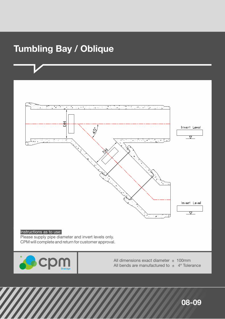
Tumbling Bay / Oblique
All dimensions exact diameter ± 100mmAll bends are manufactured to ± 4º Tolerance
Drainage
Instructions as to use:Please supply pipe diameter and invert levels only.CPM will complete and return for customer approval.

Concrete for Life08-09
Tumbling Bay / Square
All dimensions exact diameter ± 100mmAll bends are manufactured to ± 4º Tolerance
Drainage
Instructions as to use:Please supply pipe diameter and invert levels only.CPM will complete and return for customer approval.

10-11
CPM integral pipes should only be jointed using a CPM approved lubricant which is available from our sales team on 01179 812791 or email [email protected]. CPM cannot guarantee that the jointing of concrete pipes with the use of other lubricants will be successful.
CPM recommends that prior to laying the pipeline all products and equipment are checked to ensure that they are in good working order.
Additional lubricant may also be applied to the seal face to assist jointing.
For Integral seal joints
Handling of flexible jointed pipes
Remove the protective polystyrene strip by using the tape provided (where necessary)
Grip the tab of the tape and pull firmly towards the centre of the pipe (where necessary)
Lubricant should be applied to the spigot end of the pipe, ensuring the radius area and entire length of the spigot is covered.
Enter the spigot carefully into the socket and ensure that the pipes are correctly aligned.
Avoid damage when handling, especially to ends of concrete pipes and never drag or roll pipes over rough ground.
Use correct craneage for offloading, utilising canvas/fabric slings with central lift or if ordered, large diameter pipes incorporate lift pins for which the propriety head link and chain set can be used.
Pipes should be handled individually using a properly designed 'C' hook, beam sling or other purpose-designed system. Small diameter pipes may be slung through the order to avoid damage to jointing surfaces and consequent leakage of the laid pipe.
Pipe lifters are available that are designed to improve site safety and speed up installation. The pipe lifter removes the need for operatives to be placed on the back of vehicles, eliminating working at height during off-loading of deliveries. Please visit www.concretepipes.co.uk/pipe-laying-lifting for more detail or email [email protected]
Joint rings (when supplied loose) must be stored away from sunlight, heat or possible contact with any oils.
Stack pipes on even ground on timbers to protect sockets and spigots, making sure the bottom row is securely chocked.
1.
2.
3.
4.
5.
6.

Concrete for Life10-11
For 1200mm pipes and above, plus larger size ovoid pipes, CPM recommends the use of the 'Flexi-lift' lifting system where special lifting anchors can be cast into the concrete pipes at manufacture.
For rolling ring joints (‘G’ ring)
For larger pipes use of 'Flexi-lift' lifting/jointing chains
Stretch and position the seal onto the spigot of the pipe and ensure it is not twisted. Even out the stretch by lifting and releasing at several points around the spigot.Offer the pipe spigot to the socket, but keep clear of engagement by 25mm so that the joint ring is not disturbed.Enter the spigot carefully into the socket ensuring that the gasket is correctly positioned and that the pipes are correctly aligned.Under no circumstances should the joint be lubricated.
Use the equal length chains C1 and C2 for lifting and placing each pipe in the trench.
Connect the longer length chain, C3, to the pipealready laid and place the shorter length chain,C2 on the hook provided.
The pipe can then be jointed without moving the jib ofthe crane.
1. 1.
2. 2.
3. 3.
Lamell Joints
Correctly position and bed the first pipe. Prepare the bedding for the second pipe and hollow out for incoming spigot to prevent bedding material entering the joint.
Check the spigot profile for cleanliness and that the seal is the correct size. Place the seal on the spigot (as Fig 1) with the small step on the underside.
It is important that the seal is placed squarely back against the shoulder on the spigot and that the stretch is even around the gasket. This is achieved by lifting and releasing the gasket at opposite quarter points on the circumference.
Ensure that the socket of the previous pipe is wiped free of dirt and grit and reasonably dry. Under no circumstances should the joint be lubricated. Enter the spigot checking that the pipes are correctly aligned.
The joint may now be closed whilst the pipe is still supported by the crane. Check and pack, if necessary, the bedding material beneath the pipe barrel. An internal joint gap of between 10-25mm should be obtained upon completion of jointing.

12-13
Jointing
Correctly position and bed the first pipe. Prepare the bedding for the second pipe and hollow out forincoming spigot to prevent bedding material entering the joint.
Ensure the joint ring (where supplied loose) is of the correct size, is not twisted, is correctly located on the pipe spigot and the right way round.
Ensure the pipe spigot and socket are clean and undamaged.
Lubricants must not be used where ‘G’ and Lamell rings are supplied. Lubrication is required with thesuperseal integral joint (use of CPM lubricant is recommended).
Ensure the pipe to be jointed is adequately supported. The spigot should be centred carefully in the socket before jointing is completed, making sure bedding material does not enter the joint at any time.
For more detailed information on jointing see CPM Drainage Systems ‘Concrete Pipes Installation Manual’ at www.cpm-group.com
1.
2.
3.
4.
5.

Concrete for Life12-13
The air test is not covered by the European Standard, but a pipe which complies with the standard willusually comply with the air test. Failure to pass the air test will not normally preclude the acceptance of the pipeline if a successful water test can be achieved.
Ensure the test equipment is in good condition.
Inflatable stoppers are recommended for ease of use.
The test should be carried out after every 3 or 4 correctly laid and jointed pipes prior to commencement of backfill.
A successful test is achieved if the equipment shows a fall in pressure of no more than 25mm after 5 minutes, having allowed a suitable period for stabilisation.
If the pressure falls sharply and the pipes appear to have failed, the following checks must be made before contacting CPM for assistance:
(a) Check the test equipment is in good condition
(b) Check if the stoppers are leaking - use industrial soap around the edge of the stopper to provide an effective seal if necessary
(c) Check the joint rings are correctly located
Dramatic temperature changes both inside and outside of the pipe could affect the air test.Reference should be made to BS EN 752.
If after following this guidance you still have problems with our product, please contact the supplying works in the first instance, on the following telephone numbers.
Mells Works
Pollington Works
Newmains Works
Technical
CPM regrets that failure to follow the advice given may result in any subsequent claims being invalid or in a call out charge being made if CPM technical personnel have to attend on site.
Air Testing
01179 812791
01405 860591
01698 386922
01902 356220
Traditional Manholes / Soakaway Chambers
14-15
900
1050
1200
1350
1500
1800
2100
2400
2700
3000
3660+
4000+
O.D.Approxweight
/m-depth
Approxwall
thicknessDN
Available depth of section
0.25m 0.50m 0.75m 1.00m
mmmm mm kg
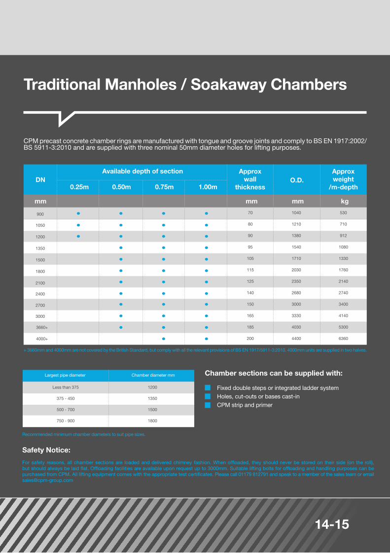
+ 3660mm and 4000mm are not covered by the British Standard, but comply with all the relevant provisions of BS EN 1917/5911-3:2010. 4000mm units are supplied in two halves.
Recommended minimum chamber diameters to suit pipe sizes.
CPM precast concrete chamber rings are manufactured with tongue and groove joints and comply to BS EN 1917:2002/BS 5911-3:2010 and are supplied with three nominal 50mm diameter holes for lifting purposes.
Safety Notice:
For safety reasons, all chamber sections are loaded and delivered chimney fashion. When offloaded, they should never be stored on their side (on the roll), but should always be laid flat. Offloading facilities are available upon request up to 3000mm. Suitable lifting bolts for offloading and handling purposes can be purchased from CPM. All lifting equipment comes with the appropriate test certificates. Please call 01179 812791 and speak to a member of the sales team or email [email protected]
Chamber sections can be supplied with:
Fixed double steps or integrated ladder systemHoles, cut-outs or bases cast-in CPM strip and primer
70
80
90
95
105
115
125
140
150
165
185
200
1040
1210
1380
1540
1710
2030
2350
2680
3000
3330
4030
4400
530
710
912
1080
1330
1760
2140
2740
3400
4140
5300
6360
Less than 375
375 - 450
500 - 700
750 - 900
1200
1350
1500
1800
Chamber diameter mmLargest pipe diameter
Concrete for Life14-15
Chamber Section
900
1050
1200
Chamber DN (mm)
Cover (heavy duty)
Cover (heavy duty)
Cover (light duty)
Chamber
Chamber
900 1200 21001500 2700 3660 / 4000
13.5m / 16.5m
4000 Vertical
2.5m3.5m 4.5m 7.5m5.5m 9.5m
1050
1200x675 access
600 x 600 access
1510 x1060 125 239 11955
1380 x930 150 300 18005
1366 x916 90 180 7505
1350 x900 150 115 9208
1350 x900 225 173 8655
600 x 600 access
1200 x 750
1200 x 750
1350 24001800 3000
4.0m 5.0m 8.5m6.5m 10.5m
Sealant Size
Manhole Section
12mm x 60mm
InternalDimensions (mm)
12mm x 80mm
ExternalDimensions (mm)
Depth mm
12mm x 120mm
Aprox Weight (kg)Palletisation
12 x 75mm 12 x 25mm
No. Per Pallet Approx Weight (kg) Banded Pack Size
Sealant length (per joint)
Primer 5 Litres / 100m 5 Litres / 75m 5 Litres / 50m None required
5
8
1350
1500
1800
2100
2400
2700
3000
3660
4000
1296
16128
16128
16128
201510
241812
241812
282114
322416
362718
4433N/A
4836N/A
Standard number of perforations per section
0.50 m DeepDN (mm) 1.00 m Deep
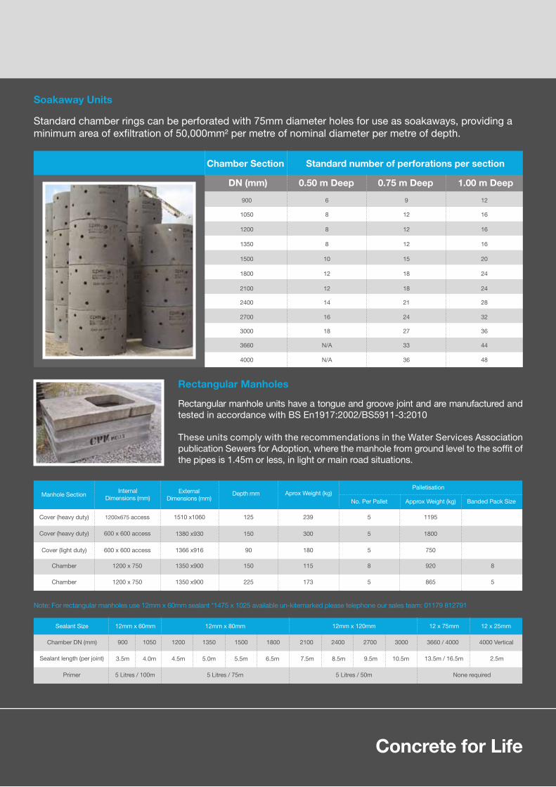
Note: For rectangular manholes use 12mm x 60mm sealant *1475 x 1025 available un-kitemarked please telephone our sales team: 01179 812791
Standard chamber rings can be perforated with 75mm diameter holes for use as soakaways, providing aminimum area of exfiltration of 50,000mm² per metre of nominal diameter per metre of depth.
Rectangular manhole units have a tongue and groove joint and are manufactured and tested in accordance with BS En1917:2002/BS5911-3:2010 These units comply with the recommendations in the Water Services Association publication Sewers for Adoption, where the manhole from ground level to the soffit of the pipes is 1.45m or less, in light or main road situations.
Soakaway Units
Rectangular Manholes
0.75 m Deep

16-17
All slabs detailed are Type 2.For details of access position, contact the technical department on 01902 356220 or [email protected] and 4000mm cover slabs are supplied in two sections and not kitemarked.All accesses have 75 x 75 corner chamfers.All cover slabs are 'heavy duty' and are suitable for use in main roads.1050mm cover slab 750 x 750 central opening is 1400 OD1350mm cover slab 1200 x 675 central opening is 1730 OD
1.2.3.4.5.6.7.
ChamberDN
MaximumThickness
mm mmmm
900 150 1230 X X XCC
1050 150 1230 C E XEE
1200 150 1400 To order* E XEE
1350 150 1560 To order* E CEE
1500 170 1730 To order* E CEE
1800 175 2050 To order* E EEE
2100 178 2370 To order* E EEE
2400 178 2700 To order* E EEE
2700 205 3020 To order* E EEE
3000 225 3350 To order* E EEE
3660 275 3960 To order* To order* To order*EE
4000 275 4500 To order* To order* To order*EE
235
235
356
503
890
1208
1745
2200
3380
4300
7940
10035
Standard Access Sizes (mm) Weight675² access
OverallDN
600 x 600 675 x 675 750 x 750 750 x 600 kg1200 x 675
CPM offer a range of standard heavy duty cover slabs from DN900 to DN4000 to BS EN 1917:2002/BS 5911-3:2010 as well as a wide range of standard specials which are outside the British and European standard but are regularly used throughout the industry as well as a bespoke range of 'one offs' that require that "extra special something".
Cover Slabs
Notes
*Made to order / E=Eccentric / C=Central

Concrete for Life16-17
As demand for high loading and multi access cover slabs has risen, CPM has become experts in both the design and manufacture, producing a wide range of bespoke cover slabs that can be manufactured to customer's specifications.
Typical examples of special cover slabs supplied are:
Landing slabs to suit DN1500 chambersections and above are manufactured with a 900mm circular access.
Reducing slabs to suit up to and including DN4000 chamber sections are generally manufactured with a 900mm, 1050mm or 1200mm circular reducing section.
Reducing slabs are generally manufactured with a built in ring.
Landing Slabs
Special Cover Slabs
For pumping stations and incorporating davits and/or rebates
Extra heavy duty slabs for airports and ports
Extra-large accesses
Slabs designed to comply with Highways Agency Specifications
Multiple accesses
Non-circular slabs
Slabs with customers own reinforcement design
Reducing Slabs
House Inspection Chambers
18-19
600 x 450 150 50 44 32 1410 16 512
600 x 450 225 50 58 20 1160 10 580
600 x 450 300 50 86 16 1380 8 690
750 X 600 150 60 67 16 1070 8 535
750 X 600 225 60 100 10 1000 5 500
1000 X 675 150 65 83 16 1330 8 665
750 X 600 300 60 134 8 1070 4 535
1000 X 675 225 65 130 10 1300 5 650
Depth ofSections (mm)
InternalDimensions (mm)
Wall Thicknessmm
Weight of Sectionsmm
Palletisation
No. Per Pallet Approx Weight (kg) Banded Pack Size (kg)Number Banded
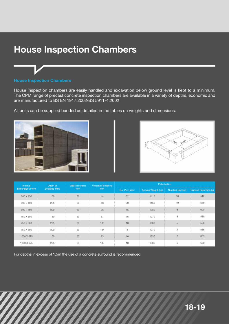
House Inspection chambers are easily handled and excavation below ground level is kept to a minimum. The CPM range of precast concrete inspection chambers are available in a variety of depths, economic and are manufactured to BS EN 1917:2002/BS 5911-4:2002
All units can be supplied banded as detailed in the tables on weights and dimensions.
For depths in excess of 1.5m the use of a concrete surround is recommended.
House Inspection Chambers

Concrete for Life18-19
A x B
A x B
E
E
A x B
C x D
F
F
kg
kg
85
120
60
110
825 x 675
845 x 680
600 x 450
600 x 450
42
46
10
10
420
1010
5
5
210
505
60
120
50
110
870 x 720
865 x 715
750 x 600
750 x 600
44
67
10
10
440
1220
5
5
220
610
60501150 x 8251000 x 675 89 10 890 5 445
To suit chamber sections
(mm)
To suit chamber sections
(mm)
OverhallDimensions
(mm)
OverhallDimensions
(mm)
Effective depthof sections
(mm)
Effective depthof sections
(mm)
Overhall depthof sections
(mm)
Overhall depthof sections
(mm)
Weight ofsections
(mm)
Weight ofsections
(mm)Palletisation
Palletisation
No. Per Pallet
No. Per Pallet
Weight (kg)
Weight (kg)
Weight (kg)
Weight (kg)
Banded pack size
Banded pack size
Top sections for 750mm x 600mm and larger chambers act as reducing slabs, enabling standard 600mm x 450mm covers to be fitted irrespective of the size of chambers involved.
To provide concrete top section for 1000mm x 675mm requires:
1. Top section for metal cover and frame 1000mm x 675mm (i.e. reducer).2. Top section for concrete cover 600mm x 450mm and concrete cover slab.
Concrete cover slabs are supplied to suit the top sections and are 695mm x 540mm overall, 60mm thick and weigh 55 kg.
Top sections for concrete covers weights and dimensions (All measurements in mm)
Top sections for metal cover and frame weights and dimensions (All measurements in mm)
600mm x 450mm top section for concrete cover
1000mm x 675mm top section for metal cover/reducing slab
600mm x 450mm top section for metal cover
600mm x 450mm concrete cover slab
Caissons
20-21
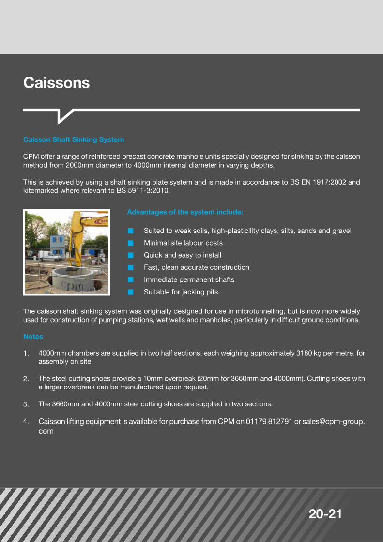
CPM offer a range of reinforced precast concrete manhole units specially designed for sinking by the caisson method from 2000mm diameter to 4000mm internal diameter in varying depths.
This is achieved by using a shaft sinking plate system and is made in accordance to BS EN 1917:2002 and kitemarked where relevant to BS 5911-3:2010.
Caisson Shaft Sinking System
Advantages of the system include:
Notes
4000mm chambers are supplied in two half sections, each weighing approximately 3180 kg per metre, for assembly on site.
The steel cutting shoes provide a 10mm overbreak (20mm for 3660mm and 4000mm). Cutting shoes with a larger overbreak can be manufactured upon request.
The 3660mm and 4000mm steel cutting shoes are supplied in two sections.
Caisson lifting equipment is available for purchase from CPM on 01179 812791 or [email protected]
The caisson shaft sinking system was originally designed for use in microtunnelling, but is now more widely used for construction of pumping stations, wet wells and manholes, particularly in difficult ground conditions.
1.
2.
3.
4.
Suited to weak soils, high-plasticility clays, silts, sands and gravel
Minimal site labour costs
Quick and easy to install
Fast, clean accurate construction
Immediate permanent shafts
Suitable for jacking pits
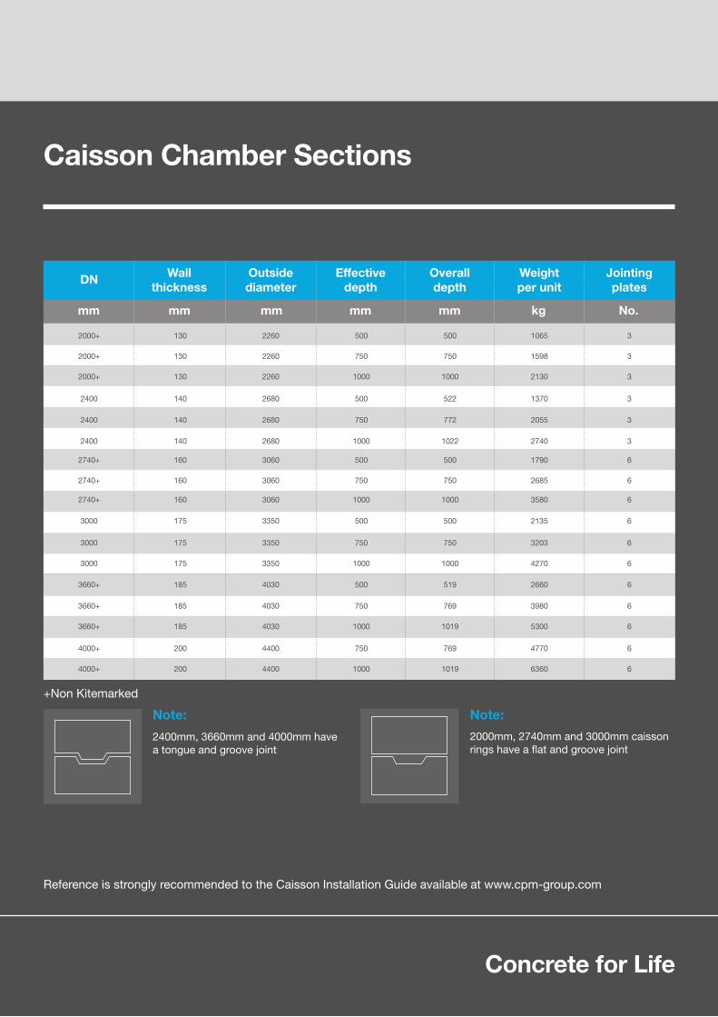
Caisson Chamber Sections
Concrete for Life20-21
Note:
Reference is strongly recommended to the Caisson Installation Guide available at www.cpm-group.com
Note:
DN
2000+ 130 2260 1065 3500500
2000+ 130 2260 1598 3750750
2000+ 130 2260 2130 310001000
2400 140 2680 1370 3522500
2400 140 2680 2055 3772750
2400 140 2680 2740 310221000
2740+ 160 3060 1790 6500500
2740+ 160 3060 2685 6750750
2740+
3000
3000
3000
3660+
3660+
3660+
4000+
4000+
160
175
175
175
185
185
185
200
200
3060
3350
3350
3350
4030
4030
4030
4400
4400
3580
2135
3203
4270
2660
3980
5300
4770
6360
6
6
6
6
6
6
6
6
6
1000
500
750
1000
519
769
1019
769
1019
1000
500
750
1000
500
750
1000
750
1000
Wallthickness
Outsidediameter
Effectivedepth
Overalldepth
Weightper unit
Jointingplates
mm mm mm mm mm kg No.
2400mm, 3660mm and 4000mm have a tongue and groove joint
2000mm, 2740mm and 3000mm caissonrings have a flat and groove joint
+Non Kitemarked

Caisson Cover Slabs
22-23
Caisson cover slabs weights and dimensions
2000 185 200
2400 163 178
2740 185 200
3000 200 225
3660* 260 275
4000*
*3660mm and 4000mm cover slabs are supplied in two halves
Reference is strongly recommended to the Caisson Installation Guide, as non-compliance may result in installation problems for which CPM can accept no responsibility.
260 275
1690
2200
3170
4300
7940
10350
2370
2700
3060
3350
3960
4500
Approx weight(6752) AccessOverall diameterEffective thickness Overall thicknessDN
mm mm mm mm kg
Reducing slabs are available, please contact sales for details on 01179 812791or [email protected]
A full installation guide is available for download at www.cpm-group.com/drainage/caissons
1.
2.
Concrete for Life22-23
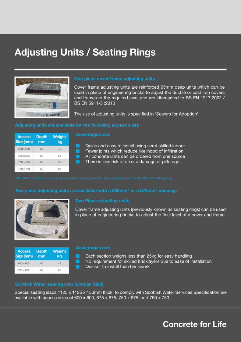
Scottish Water seating slab (Lothian Slab)
Adjusting units are available for the following access sizes
*600 x 600 Eccentric/ Corbel units have an eccentric opening which is used in conjunction with a 750 x 600 cover slab opening.
Two piece adjusting units are available with a 600mm² or a 675mm² opening.
Special seating slabs 1125 x 1125 x 150mm thick, to comply with Scottish Water Services Specification are available with access sizes of 600 x 600, 675 x 675, 750 x 675, and 750 x 750.
Two Piece adjusting units
Cover frame adjusting units (previously known as seating rings) can be used in place of engineering bricks to adjust the final level of a cover and frame.
One piece cover frame adjusting units
Cover frame adjusting units are reinforced 65mm deep units which can be used in place of engineering bricks to adjust the ductile or cast iron covers and frames to the required level and are kitemarked to BS EN 1917:2002 / BS EN 5911-3 :2010
The use of adjusting units is specified in ‘Sewers for Adoption’
Advantages are:
Each section weighs less than 25kg for easy handlingNo requirement for skilled bricklayers due to ease of installationQuicker to install than brickwork
AccessSize (mm)
Weightkg
Depth mm
600 x 600
750 x 675
65 48
65 60
Advantages are:
Quick and easy to install using semi-skilled labourFewer joints which reduce likelihood of infiltrationAll concrete units can be ordered from one sourceThere is less risk of on site damage or pilferage
AccessSize (mm)
Weight kg
Depth mm
*600 x 600
675 x 675
750 x 600
750 x 750
65 70
65
65
65
65
70
80
Adjusting Units / Seating Rings

24-25
Gully Pots
CPM gullies are typically used in highways and parking areas and are produced monolithically on fully automated machines, providing a strong robust unit that needs no concrete surround and are not subject to floatation.
Precast concrete road gullies can be supplied with adaptors for connection to clay or plastic pipes.CPM gullies are delivered inverted and should be offloaded, turned and handled using a webbing strap in choker fashion.
Gully cover slabs are available in both square and 'U' shaped, with handling recesses for lifting brackets and are designed as a seating for a gully grate and used on top of a 450mm gully. CPM gully cover slabs are quick to lay and sit flush to the kerb for enhanced stability, eliminating brickwork joint 'weakspots'.
A 65mm thick version also available.
Gully weights and dimensions
Gully cover slabs
A Bmm C Litres
375 55 698 750 50 125
450 55 780 750 70 90
375 55 698 900 69 108
450 55 780 900 95 80
450 55 780 1050 120 73
DNNominal
wall thicknessWidthmm
Effective depthmm
CapacityNo. per
full 23.5 tonneload
188
260
216
290
320
Weight per unit
kg
150
150
150
150
150
Outlet i/diamm
D No
250
250
250
250
250
Appoximatemeasurement
mm
E
Square
U
750 X 650 80
585 X 650 50
SlabDimensions
(100mm thick)Kg
(100mm thick)

Concrete for Life24-25
The gully adaptor is a versatile elastomeric sealing adaptor ring manufactured in EPDM rubber to BS 2494 Type D.This table shows the tolerant of a range of pipe diameters and profiles - for use only with CPM Group kitemarked concrete gullies.
For pipes not included in the table, the following criteria should be used for selection of correct gully adaptor.
No. 1501 - Spigot diameter - 160mm to 180mmNo. 1502 - Spigot diameter - 175mm to 190mm
Procedure for installation and selection of gully adaptor
1. Ensure the gully outlet socket is clean. Any hard points should be removed.
2. Fit adaptor into socket. The adaptor seals are designed slightly larger than the socket to ensure positive location and an effective seal. Care should be taken to even out the seal to remove folds, although if left, this will occur naturally.
3. Place pipe in adaptor and push home.
Lubricant requirements:
i) Smooth plastic pipe - requires no lubricant.
ii) Supersleve pipe - can be jointed dry with care, but lubricant may be used to assist jointing.
ii) Densleeve/Hepseal/Corrugated pipes - lubricant such as water/soap, silicone etc. is required for jointing purposes. In some instances for corrugated pipes it may be advisable to place the pipe in the adaptor prior to its location in the gully outlet.
Gully Adaptors
Type of PipeTo Suit Pipe Number of gully adaptor requiredto suit type of pipe
DN 1501 1502
uPVC pipe to BS4660
aquapipe - corrugated
ultrarib
twin wall PVC - corrugated
supersleeve
densleeve
hepseal
plastic
plastic
plastic
plastic
clay
clay
clay
160
150
150
150
150
150
150

After an extensive research programme, CPM introduced the 1200mm perfect manhole system in October 2009 to meet the challenges of modern day construction. Today it is available in 1200mm, 1500mm and 1800mm diameters and comprises of a monolithic precast concrete base (available pre-benched in any configuration within just days of requisition), a sealed chamber ring (with a thicker wall than a traditional ring), a rubber joint (so no tokstrip or similar product is required) and a sealed cover slab (supplied with your required access).
For other sizes please Telephone: 01538 380500 / Email [email protected]
This unique system of products combine to form the CPM perfect manhole system; designed and manufactured to last a minimum of 120 years that provides a sealed manhole system that gives up to 40% savings on greenhouse emissions compared to traditional manhole construction and eliminates the need of ready mixed concrete to form the traditional base, chamber benching and further concrete to surround the manhole. A complete manhole can be installed in as little as 25 minutes, and making safe site practice a real winner when using the perfect manhole as it reduces the need to work in confined spaces and eliminates the need for wet trades resulting in rapid construction compared to traditional methods as well as a reduction in time for the excavation space to be open.
The Perfect Manhole System
The Perfect Installation / Time Line
17:05
1
17:10
2#2#
17:15
3#3#
17:20
4#
17:25
5#5#
26-27
#1 #2 #3 #4 #5

Concrete for Life
Attributes of the Perfect Manhole System
Quality of the Perfect Manhole System
The long term benefits
Build Greener
Build Leaner
Build Faster
Build Safer
Build Quality
Up to 40% lower greenhouse gas emissions
Saves material and labour / No waste
Speedy installation
No confined space working, excavation closed quicker
CPM’s Perfect Manhole is produced in a quality controlled factory environment
Perfect Manhole complies with BSEN1917:2002 and BS5911-3.
CPM’s Perfect Manhole is accepted for use by all major UK companies and is included inSewers for Adoption 7th edition.
CPM’s Perfect Manhole is made from high quality durable concrete with a minimum of 120 year design life.
Easy access for inspection - reduces maintenance and running costs.
Watertight Manhole – prevents water infiltration into the manhole system and ex-filtrationof raw sewage or dirty water from the manhole into the surrounding area.
The Perfect Manhole take off tool / ConfiguratorAvailable from CPM’s website www.cpm-group.com is the perfect manhole take off tool and configurator. Just input your 1200mm or 1500mm manhole details and email to [email protected] and we will send you back a complete schedule and costs for your project.
26-27

Advantages / Perfect Manhole System
*Watertightness is defined in BS EN 1917 as resisting a 5m head for 15 minutes. This is to simulate a temporary surcharge condition not a permanent head of water.*Shafts in high water tables are subject to buoyancy effects. For further information please contact the CPM Group Technical team.
Safer constructionNo requirement to form a concrete surround. Reduction of open excavation.
GHG savingsUp to 40% savings on GHG emissions compared with traditional construction.
Fast installationThe modular solution eliminates the need for wet trades resulting in rapid construction compared to conventional methods.
No need to surround in concrete unless specifically required130mm wall thickness.
Available at short noticeOur modern methods of production enables just in time delivery of all components including bases at short notice.
WatertightThe combination of a thicker wall and rubber joints ensures a watertight structure.*
No water ingress into sewerage network reduces treatment costsThe combination of a 130mm wall and sealed rubber joint withstand 5m head of pressure.*
Combined seal includes load distributorLoad distribution ensures even distribution of vertical loads.
Allows joint inspectionCorrect installation can be visually confirmed.
Fully tested under factory conditionsThe whole system from base to cover slab is subject to testing.
Kitemarked solution manufactured under factory conditionsComplies with the requirements of BSEN 1917 and BS5911-3
Concrete for life – built to last.High quality durable concrete with a minimum 120 year design life.
Flexible connectionsThe Perfect Manhole can be connected to plastic, clay, cast iron or concrete - giving you a larger choice.
28-29

Ticking all the boxes
Extra Services
Available in 1200mm, 1500mm and 1800mm diameterFor other sizes please call 01538 380500 or Email [email protected]
Concrete for Life
Efficient constructionAvailable in varying depths for efficient construction.
Base optionsAvailable pre-benched or plain bottom with or without inlet / outlets.
Pre-fit optionsHydro-Brake®, penstocks, non-return valves, and filters can be pre-fitted in the factory.
Customer choiceThe perfect manhole is available with or without double steps. Sealed chamber rings can be used without the perfect base.
Cover choice.Each perfect manhole is available with a cover slab opening of 600 x 600mm, 675 x 675mm, 750 x 600mm or 1200 x 675mm
Full take-off service available.
Lifting apparatus available for fast, effective and safe handling.
Full installation guide available.
Hydro-Brake® / Penstocks and valves can be pre-fitted.
28-29

Perfect Manhole / Diagrams
Please note that there is a 1 in 9 gradient for the 1200mm perfect manhole and a 1 in 18 gradient for pipes 450mm upwards for the 1500mm perfect manhole and the angles between adjacent connection cannot be less than 24 degrees.
Please use this diagram to scan/photocopy and forward your requirements to [email protected]
Outlet - A0
Inlet - E1
Inlet - E2
Inlet - E3
Inlet - E4
Customer Product Reference
Site Originator
Customers MH Ref
Required fall across main channel (E1 To A0)
Double steps position if Required (DEG)
Outlet / Inlet Positions (DEG) Pipe Size Gradient Pipe Type
30-31
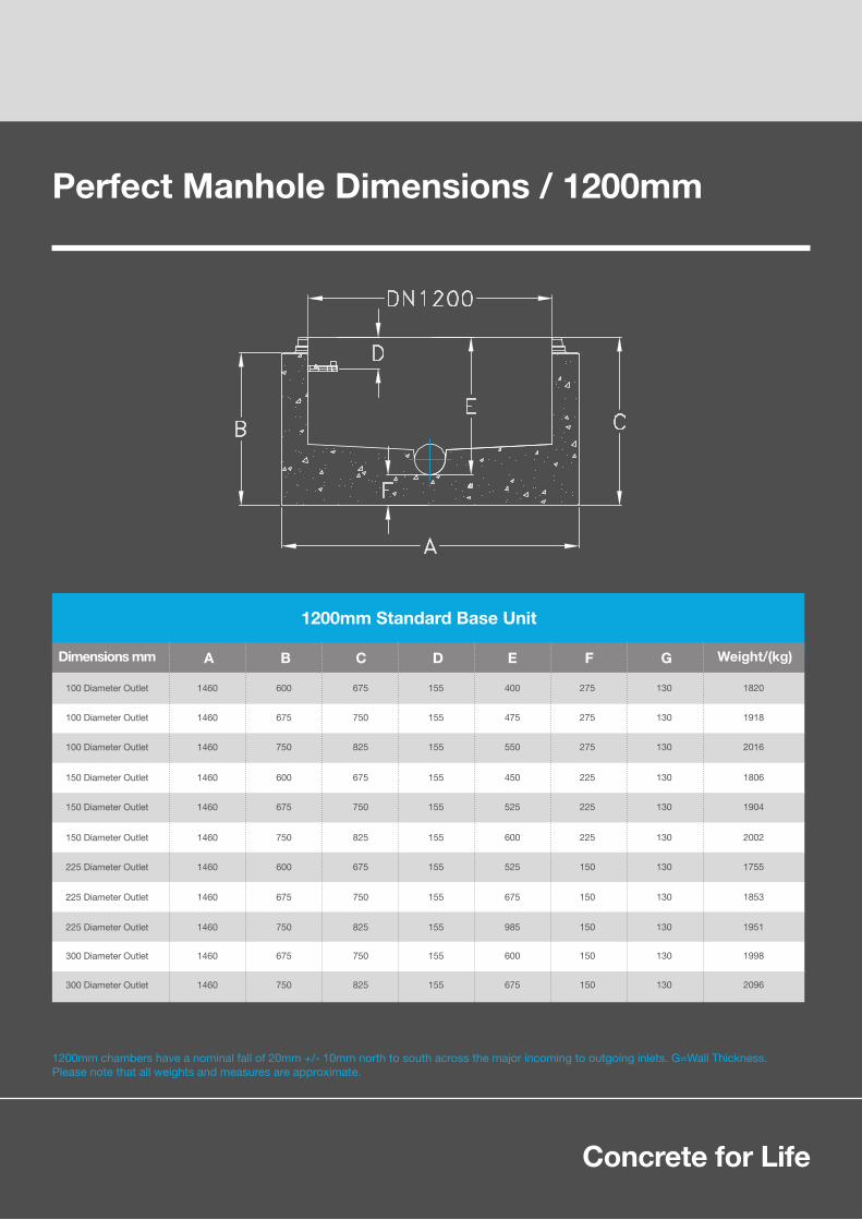
Perfect Manhole Dimensions / 1200mm
Concrete for Life
1200mm Standard Base Unit
Dimensions mm
100 Diameter Outlet
100 Diameter Outlet
100 Diameter Outlet
150 Diameter Outlet
150 Diameter Outlet
150 Diameter Outlet
225 Diameter Outlet
225 Diameter Outlet
225 Diameter Outlet
300 Diameter Outlet
300 Diameter Outlet
1460
1460
1460
1460
1460
1460
1460
1460
1460
1460
1460
600
675
750
600
675
750
600
675
750
675
750
675
750
825
675
750
825
675
750
825
750
825
155
155
155
155
155
155
155
155
155
155
155
400
475
550
450
525
600
525
675
985
600
675
275
275
275
225
225
225
150
150
150
150
150
130
130
130
130
130
130
130
130
130
130
130
1820
1918
2016
1806
1904
2002
1755
1853
1951
1998
2096
Weight/(kg)A DB EC F G
1200mm chambers have a nominal fall of 20mm +/- 10mm north to south across the major incoming to outgoing inlets. G=Wall Thickness.Please note that all weights and measures are approximate.
30-31

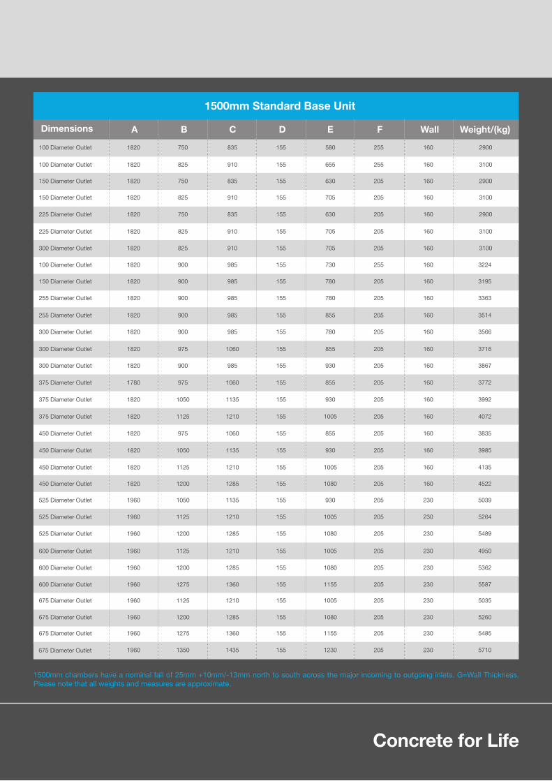
Perfect Manhole Dimensions / 1500mm
Typical Perfect Manhole Images
32-33
Concrete for Life32-33
1500mm chambers have a nominal fall of 25mm +10mm/-13mm north to south across the major incoming to outgoing inlets. G=Wall Thickness. Please note that all weights and measures are approximate.
1500mm Standard Base Unit
Weight/(kg)A DB EC F WallDimensions
100 Diameter Outlet
100 Diameter Outlet
100 Diameter Outlet
150 Diameter Outlet
150 Diameter Outlet
225 Diameter Outlet
225 Diameter Outlet
300 Diameter Outlet
150 Diameter Outlet
255 Diameter Outlet
255 Diameter Outlet
300 Diameter Outlet
300 Diameter Outlet
300 Diameter Outlet
375 Diameter Outlet
375 Diameter Outlet
375 Diameter Outlet
450 Diameter Outlet
450 Diameter Outlet
450 Diameter Outlet
450 Diameter Outlet
525 Diameter Outlet
525 Diameter Outlet
525 Diameter Outlet
600 Diameter Outlet
600 Diameter Outlet
600 Diameter Outlet
675 Diameter Outlet
675 Diameter Outlet
675 Diameter Outlet
675 Diameter Outlet
1820
1820
1820
1820
1820
1820
1820
1820
1820
1820
1820
1820
1820
1820
1780
1820
1820
1820
1820
1820
1820
1960
1960
1960
1960
1960
1960
1960
1960
1960
1960
900
750
825
750
825
750
825
825
900
900
900
900
975
900
975
1050
1125
975
1050
1125
1200
1050
1125
1200
1125
1200
1275
1125
1200
1275
1350
985
835
910
835
910
835
910
910
985
985
985
985
1060
985
1060
1135
1210
1060
1135
1210
1285
1135
1210
1285
1210
1285
1360
1210
1285
1360
1435
155
155
155
155
155
155
155
155
155
155
155
155
155
155
155
155
155
155
155
155
155
155
155
155
155
155
155
155
155
155
155
730
580
655
630
705
630
705
705
780
780
855
780
855
930
855
930
1005
855
930
1005
1080
930
1005
1080
1005
1080
1155
1005
1080
1155
1230
255
255
255
205
205
205
205
205
205
205
205
205
205
205
205
205
205
205
205
205
205
205
205
205
205
205
205
205
205
205
205
160
160
160
160
160
160
160
160
160
160
160
160
160
160
160
160
160
160
160
160
160
230
230
230
230
230
230
230
230
230
230
3224
2900
3100
2900
3100
2900
3100
3100
3195
3363
3514
3566
3716
3867
3772
3992
4072
3835
3985
4135
4522
5039
5264
5489
4950
5362
5587
5035
5260
5485
5710

Perfect Manhole System / 1800mm
Typical Perfect Manhole Images
After the successful introduction of the 1200mm and 1500mm perfect manhole system, CPM has developed an 1800mm sealed manhole that can be used for precast concrete pipes up to 900mm diameter.
The system includes a cast-in base and incorporates the concrete butt pipes into the chamber base and pipe channel; this only leaves the benching to be completed on site.By leaving the benching out of the base element, the weight of the unit is reduced to between5.0 and 5.5 tonnes depending upon the configuration.
Deeper manholes are accommodated by using a reducing slab to a 1200mm sealed manhole.
The 1800mm Perfect Manhole system can be supplied with either double steps or with anintegrated ladder system which is available from CPM.
As the 1800mm sealed manhole system is a bespoke precast product, standard measurements cannot be given as each is individual.
For further information please call 01538 380500 or email [email protected]
34-35
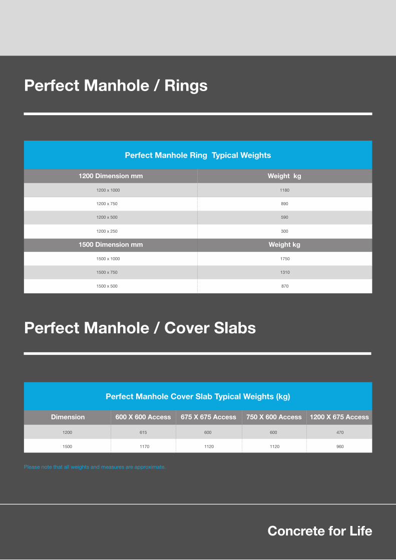
Perfect Manhole / Rings
Perfect Manhole / Cover Slabs
Concrete for Life34-35
Perfect Manhole Ring Typical Weights
Perfect Manhole Cover Slab Typical Weights (kg)
1200 Dimension mm
1500 Dimension mm
600 X 600 AccessDimension 675 X 675 Access 750 X 600 Access 1200 X 675 Access
1200 x 1000 1180
1200 x 750 890
1200 x 500 590
1200 x 250 300
1500 x 1000
1500 x 750
1500 x 500
1750
1310
870
1200 615 600 600 470
1500 1170 1120 1120 960
Weight kg
Weight kg
Please note that all weights and measures are approximate.

Box Culverts
36-37
Design chemical class DC-4 resistance
CPM's precast concrete box culverts are designed and manufactured in accordance with all current design specifications and relevant stands and are manufactured in both standard sizes available from stock and a bespoke range that is manufactured to customer specification, ensuring that those who require standard sizes as well as those who require something extra are catered for.
As well as culverts, CPM are able to include end walls, access points, vent holes, inlets, outlets, rungs and splayed ends. Starter bars and sockets can be added to facilitate any additional casting on site which may be required as part of the finished work.
The culverts can be supplied as standard units, on their side, vertical chambers and where being used as channels, cover slabs can be supplied separately if required
An installation guide is available from www.cpm-group.com or call 01179 812791 for a copy or email [email protected]
Typical Box Culverts
CPM box culverts suit a wide variety of applications such as:-
HighwaysStorm and foul sewersSea outfallsTunnels and subwaysUnderpassesStream crossingsVertical chambers
Open channelsRoad crossingsShaftsService tunnels and ductsAttenuation and storage tanksWater course diversion

Concrete for Life36-37
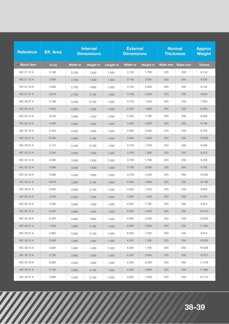
Box Culvert Range
Eff. Area
38-39
Eff. Area

Concrete for Life38-39
Table Notes:
A Adjustable size mould range - Details of splays:
MC 10.05 to MC 10.07 : 150 * 50mm MC 12.05 to MC 13.10 incl : 225 * 75mm MC 15.07 upwards : 300 * 100mm
Typical Box Culvert Images
Eff. Area

40-41
Manhole / Integrated Ladder System
CPM, in conjunction with Caswick, the market leading manhole step producer has de-veloped an Integrated Manhole Ladder system. This innovative product has been designed to provide safe access and egress to precast concrete man-holes, caisson shafts and inspection chambers. A range of rungs are a pre-fitted into the chamber to make the installation of the ladder quick, cost effective, reliable and safer than conventional ladders.
The system has WRc approval and meets the essential requirements of existing and new design codes in terms of dimensions and performance.
System advantages
Ease of Installation
Flexibility
Safety
Quality
Durability and Strength
Product Standards
The integrated manhole ladder system has the innovative ladder rungs pre-fitted into the chamber rings therefore the system is delivered to site partly pre-installedThe chamber rings are then installed in the conventional way, ensuring that the ladder steps are inlineThe Integrated Manhole Ladder System has been granted WRc approval
The Ladder Rungs are pre-fitted at 250mm centres into the chamber sections, leaving only the Stringer, Locating Bracket and End Caps to fitMinimal access to a confined space to fit ladder stringersNo lifting, drilling or temporary access required to chamber
The incorporation of the Ladder Rung in the manhole automatically takes account of the variation in depth to designNo bespoke ladder needs to be surveyed, ordered or manufacturedNo equipment hire compared to fitting traditional galvanised steel ladder
The polypropylene polymer encapsulation gives high visibility and no sharp edgesThe rung has a tread pattern to give good slip resistanceThe stringer has a circular cross section designed to give a secure hand grip unlike a conventional ladder which is normally too large to safely hold on to
Ladder rungs are kitemarked to BS EN 13101Ladder rungs are reinforced with high tensile steel tubeThe ancillary fitting brackets are made from stainless steel Grade 304 or 316
Ladder rungs are pre-fitted to ensure factory controlled performance and are pull out and deflection tested to BS5911 part 3The chemical resistance of polypropylene can be considered equivalent to Grade 316 stainless steel
The system has been designed and manufactured in accordance with the requirements specified in:BS EN 13101 Steps for underground man entry chambers / BS EN 14396 Fixed ladders for manholes

Concrete for Life40-41
Benefits of using a CPM catchpit and silt trap
Catch-pit/silt trap chamber systems
CPM has developed a range of off-site solution catchpit and silt trap manholes so why spend days constructing an in-situ catch-pit manhole on site when one-piece chambers are available now and can be installed within hours, not days!
The reinforced watertight one-piece structures offer greater design flexibility with a range of cored or pre-formed holes/cut-outs for inlet/outlet holes which come complete with seals CPM modular catchpits save money and time as they are built under factory conditions to your specification ensuring dimensional correctness as well as a high quality finish.
Design options include:
Reduced costs in construction time and on-site personnelSump depths to suit design requirementsAccommodates uPVC, twinwall, clay, ductile iron and concreteIncreased Health and Safety benefits as it reduces on-site constructionReduces wet trades for manhole constructionProduct is made and tested under factory conditionsEliminates extra transport and material wastage used with on-site construction methodsChamber bases are Kitemarked1050mm unit weighs less than one tonneBespoke design to suit customer requirementsStandard tongue and groove jointsGreatly reduced installation time on siteNone or minimal on-site fabrication required
1050mm to 3000mm standard tongue and grove complete with a cast-in reinforced base1200mm, 1500mm and 1800mm sealed manhole joint complete with cast-in reinforced basePipe inlet/outlet diameters covered by system 100mm to 1800mm

Preformed Manholes
42-43
CPM has developed an off-site large modular manhole system that is designed to speed up the installation of the manhole whilst providing a safe working environment for personnel working within the manhole.
The benefits of the wide wall section include:
For a installation sequence please see our website:www.cpm-group.com
An established and proven product range that is Quality AssuredWide wall products are supplied with a Butyl sealant which removes the need for a concrete surroundThe chamber is supplied with a reinforced cast-in baseThe chamber system provides performed inlet and outlet holes to suit pipe requirementsThe chambers are manufactured in fixed steel moulds that give a superior dimensional accuracyWide wall chambers have an inherent structural concrete strength with a 120 year design lifeChamber units are supplied with cast-in brackets for a lifting loop systemAutoCAD drawings can be providedKitemarked product range
All chamber sections are manufactured to the requirements of BS5911-3, 2100mm, 2400mm, 2700 and 3000mm are kitemarked.The base chamber is manufactured with a 200mm deep; grade C40, reinforced concrete base dowelled into the chamber unit. Concrete has a minimum cover to reinforcement of 30mm.The inlets and outlets are either pre-scored, pre-formed or cored holes (depending on size) to suit the customer’s requirements.Cover slabs are manufactured to the requirements of BS EN 1917:2002 and BS 5911-3:2010
Product specifications include:
NominalDiameter
(mm) (mm) Depth Depth Depth
OutsideDiameter
Weight per500mm
Weight per750mm
Weight per 1000mm
2100
2400
2700
3000
3660
4000
2350
2680
3000
3330
4030
4400
1070
1370
1700
2070
2650
N/A
1605
2055
2550
3105
3980
4770
2140
2740
3400
4140
5300
6360

Product specifications include:
Concrete for Life42-43
Accessories
Corner filler unit with straps and cleatsLifting and handling equipment
CPM L Shape precast concrete walling makes wall units easier to use as both faces of the unit are vertical and there are only two thicknesses of wall for the complete range.
CPM L shape retaining wall units are manufactured from C40/50 concrete with 50mm nominal cover to reinforcement.
They can be used in very severe exposure conditions as defined in BS 8110 Part 1 and severe exposure conditions as defined in BS 5400 Part 4. Stock units are suitable for loading from either side, with maximum loading from a level fill with a density of 19kN/m³ and 10kN/m² live load surcharge or sloped up at max. 30° to an equivalent height to the wall.A qualified engineer should check the foundation and wall stability.
Holes (32 dia) are provided to connect units with insitu foundation to provide stability against sliding and overturning. Holes in the wall stem provide lift points, corner filler strap cleat fixings and weep holes.
L Shape Retaining Walls
Dimensions (mm)
Height (mm) CA D
1000 120 400 135 x 135 470
1500 120 400 135 x 135 626
2000 190 500 135 x 175 1350
2500 190 500 650 175 x 175 1810
3000 190
650
650
1000
1500
1500
1000
1500
2000
2500
3000 500 650 175 x 175 2040
B E Chamfer Weight (kg)
*Bespoke only
Complete UK Coverage
HEAD OFFICE / ENGLAND / WALES SALES AND SOUTHERN WORKSCPM Group Ltd, Mells Road, Mells,Nr Frome, Somerset, BA11 3PDTel: 01179 812791 Fax: 01179 814511
NORTHERN WORKSCPM Group Ltd, Pollington, Goole,East Riding of Yorkshire, DN14 0DUTel: 01405 860591 Fax: 01405 863606
SCOTLAND SALESCPM Group Ltd, 101 Main Street, Newmains,Wishaw, Lanarkshire, ML2 9BGTel: 01698 386922 Fax: 01698 387167
PERFECT MANHOLE SALESCPM Group Ltd, Barnfields, Leek,Staffordshire, ST13 5QGTel: 01538 380500 Fax: 01538 380510
TECHNICAL OFFICESCPM Group Ltd, CPM House,Heath Mill Road, Wombourne,Staffordshire, WV5 8APTel: 01902 356220 Fax: 01902 356221
Designed by Pixel Creative · www.pixel-creative.co.uk