cpm booster card - delft spline systems · pdf filecard is called the cpm booster card, ......
TRANSCRIPT

CPM Booster CardRetrofit card for Isel IMC4 controllers.
User’s Guide

CPM Booster manual AxeMotion
2

AxeMotion CPM Booster manual
3
CPM Booster Card
User’s Guide
Version 1.0
January 2010
Retrofit card for Isel IMC4 controllers.
Hardware: Copyright © 2008-2010 AxeMotionSoftware: Copyright © 2008-2010 Bertrand Lenoir-WelterManual: Copyright © 2008-2010 Delft Spline Systems
All rights reserved.

CPM Booster manual AxeMotion
4

AxeMotion CPM Booster manual
5
CONTENTS
1 THE BOOSTER CARD 7
2 HARDWARE SETUP 8
3 SOFTWARE SETUP 10
4 OPERATION 12
Appendix A - CNC control theory 13
Appendix B - Card settings 16
Appendix C - Card specifications 19

CPM Booster manual AxeMotion
6

AxeMotion CPM Booster manual
7
CHAPTER 1: THE BOOSTER CARD
The CPM machine is one of the most successful machines made by German manufacturer Isel. The machinefeatures a closed cabinet built of metal, which is a stable frame for the machine and guarantees a safe operationas milling is possible only with the door closed. Ballscrews and bearings are well-protected from chips and dust.The CPM series are based on the IMC4 stepper motor controller: a proven design with a track record that showsa great reliability.
Drawback of this IMC4 controller is that it is not a very fast controller: between every two movements the cutterwill briefly stop. So at the end of a movement the machine will decelerate, stop for a moment and then againaccelerate for the next movement. As a result the machine moves rather jerky when executing series of G1movements (linear interpolations). The machine makes a very typical “staccato” rumbling noise that will makethe complete table underneath vibrate with the machine.This jerky movement style comes with serious disadvantages:- It takes a lot of time. Especially when the movements are short: then the machine does not even come close tothe nominal feedrate as it is decelerating and accelerating all the time.- The resulting surface quality is not very good- Machining metals is not possible.Second drawback of the IMC4 is that communication with the PC a serial cable is used (RS232). This is a ratherobsolete method: most current PCs no longer have a serial port present. For communication with the PC currentdevices use USB.
Stepper motor control has evolved a lot since the IMC4 controller was designed: fluid movements and a machinethat keeps up speed are very well possible nowadays.Axemotion is a specialist in controlling stepper motor based machines. Based on this knowhow, Axemotion hasdeveloped an plug-in card for the IMC-4 controller that changes it to an up-to-date stepper motor controller. Thiscard is called the CPM Booster card, and you new are reading the manual for this card.
The CPM Booster card features:- USB Interface- up to 4 axes controlled simultaneously- look-ahead buffer (250 vectors).- supports all IMC4 functionality
The Booster card will not function with the Isel Remote or RemoteWin software: it needs to use Kay or Galaadas control software. This is because the software must be able to do the inverse kinematics: analyze themovements and determine the optimum speeds at each moment. Also see Appendix A of this manual.
Installing this card will save a lot of time for NC files with loads of very small G1 movements. Reducing timewith 50% is easily possible, in some cases the time gain will even be higher !An extreme example was a 8 Mb NCP file for a small object (jewelry, ca 40x50x10 mm). Very accuratetoolpaths with G1 movements only: small distance between the toolpaths and small stepsize. A conical cutterwith a 0.1 mm tip was used. Here the difference between the original IMC4 and the Axemotion booster wasenormous:- IMC4 242 minutes (so 4 hours 2 min)- AxeMotion 40 minutesSo a milling time reduction of over 80 % !!!
Check the videos on www.spline.nl to see the different movement style. You can see the same NC file (a bottlemodel) being machined with the original IMC4 (51 minutes) and with a Boosted version (26 min). Note thatseeing and also hearing the difference on the video will tell you more than only these numbers.
For NC files with long movements (say G1 movements of 20 or more mm long no time gain will be present: thenalso with the original IMC4 the machine will be on speed most of the time. And the maximum speed (50 mm secfor CPM machines with a 10 mm ballscrew pitch) is caused by the maximum rotation speed of the stepper motorsand cannot be improved.

CPM Booster manual AxeMotion
8
CHAPTER 2: HARDWARE SETUP
How to insert the IMC4 Booster card into the IMC4 controller.
The IMC4 controller is located on the back side of your Isel CPM or ICP machine. You can see it after removingthe back cover panel of the machine (six hexagon screws). Note that this panel is connected to the machine by anearth wire.In order to insert the AxeMotion Booster card you also need to remove the back panel of the controller (threePhillips screws and some double sided tape). Carefully remove this panel in order not to damage the cable thatconnects the ventilator in the panel to the controller (you can disconnect the plug to completely loosen the panel).
Now you can see the PCB board of the IMC4 controller, as shown in the picture above.From this controller you need to remove 7 chips: 2 square PLCs and 5 rectangular chips. Note that for removingthe PLCs you need a tool called “PLCC extractor”. For the chips using a chip extractor is advised as well: whenyou correctly remove them (without bending the pins) you will be able to replace them later if needed. Makenotes which chip was placed in which connector, and how it was orientated.
The picture above shows the 7 chips removed, indicated by 7 red circles.You can also see 3 blue circles: the IMC4 Booster card needs to be pressed into these three chip connectors. Tomake this possible the booster card comes with some extra connectors to bridge the distance between the twoboards.
Placing the board will prove to be the most difficult part of the complete installation procedure: normally when

AxeMotion CPM Booster manual
9
pressing one chip down it is possible to gently rock the chip while pressing in order to make it slide home. Ashere three connectors are present this is not possible. And in addition it is not possible to see what you are doingas the Booster card completely blocks your view.
Check carefully if the pins of the two 32 pins (2x16) connectors are all well placed on the two 32 pins sockets ofthe IMC4. If that is OK you can firmly press on the "middle" of each these two connectors. All pins must becompletely inserted into the socket. After that, the PLC connector will slide into position when pressing that partof the booster board.
As a result all pins should have been completely inserted, and the Booster card needs to be exactly parallel to theIMC4 main board. The booster board also may not be bended. In case this plugging in has not been done completely correct you will get unpredictable behavior. In the pictureabove you can see a card that has NOT yet been fully plugged in (note that your booster card may have adifferent color).
Finally you can plug a standard USB cable into the IMC4 Booster board and lead that to the outside of themachine. Or you can mount a USB connector in the back wall of your machine, next to the other connectors.Connect the booster card with the inside of that connector using a short USB cable: you now can close themachine and use a second USB cable to connect PC to machine. See the two pictures below.

CPM Booster manual AxeMotion
10
CHAPTER 3: SOFTWARE SETUP
2.1 How to install the Drivers for the Booster Card.
Do NOT use a Win95, Win98 or Win ME based PC for this card: the USB system on these PCs is too old andyou will run into problems when using the Booster card. Use Win 2000, XP, Vista or newer.
The IMC4 Booster Card makes your milling machine a USB device, so you will need USB drivers in order to useit. Unfortunately these drivers do not yet come with a Setup program: you need to manually install them.You can download the driver files from http://www.axemotion.com (Download menu) There you can find a file called “AxMo 2-n.nn.nn.zip ” where n.nn.nn is the version number. Must be 2.02.04 ornewer. Unpack this file and remember into which directory.
Next, when you connect the USB cable from the Booster board to your PC, Windows will start the NewHardware found wizard. Make this wizard look in the directory just mentioned and use the driver it will findthere. It might be that this needs to be done twice as the driver comes in two parts.
2.2 How to configure Kay to work with the Booster Card.
Your Isel machine has been delivered with a Kay CD. At least when you have bought the machine from DelftSpline Systems. In case you used the Remote or RemoteWin control software you also need to buy a Kay licenseto be able to use the booster card. As a first step you will need to install Kay from this CD: later updates willonly work when a valid Kay license is present already.
Next you need to download and install such update, as the version on your CD may not yet support the boostercard. For downloading please visit www.galaad.net Go to the Download page and download an “Update formain modules” in your preferred language. Unpack this ZIP file into the directory of your original Kayinstallation, which by default will be C:\Program Files\Galaad\Just over-write the old files with the new versions.
Now you are ready to start.In contrast to how the machine behaved earlier, you cannot yet press the green Power button on the front of yourmachine to power up the IMC4 controller: Kay will now tell you when this can be done.
Start Kay, cancel the file load (or load a small NC file) and open the Machine Parameters (Parameters menu,Machine ...). It might be that these will be opened automatically when Kay cannot find the currently selectedmachine (Note that the dialog is called “Mill parameters”).
It may be that in a moment you will see a message that Kay is automatically updating the firmware of the CNCCard. That is OK: as the software changes more often than the hardware this is way to keep them both up-to-date.

AxeMotion CPM Booster manual
11
The first tab of this dialog is called Table and is shown above left.Here select your machine: make sure to choose the type with “/ AxeMotion” added to the original name.You also need to check the values for the ballscrew pitch: most CPM machines have 10 mm per revolution, itmight be that Kay incorrectly sets these to 4. If so then you need to change 4 to 10 for all three axes. Or ofcourse the other way round when you have a machine with 4 mm screws.Motor Steps needs to be 1600 for all three axes (detailed information: the Isel stepper motors have 200 steps,however are operated using a 1/8 step microstep resolution which results in 1600 steps).In case you are using a fourth axis, the Resolution needs to be 26284 (type 1:16) or 78792 (type 1:50),
The second tab page is called Controller, as shown above right, and the settings should be correct automatically:Controller type is AxeMotion IMC-Plugin and Port is USB. Now press the button “More” just right of the controller type IMC-Plugin.
The AxeMotion sub-dialog shown above will pop up.Important here is to check the option “Update CNC card firmware automatically”. This is a great option, as itallows you to renew the firmware on your booster card. Downloading new software is easier than ordering a newcard, so this is an easy way to keep your card updated. It is important to check this option as your card may havebeen in stock for some time and thus may have old firmware.
All other settings in this dialog should be automatically correct, at least for machine with 10 pitch ballscrews. Ifyou have a machine with 4 or 5 mm pitch please check Appendix B of this manual for more detailedinformation. In case of 5 mm pitch use the advised values for 4 mm. Important: for such machine you also needto change the maximum speed of the machine in Kay (Speeds tab): needs to be 20 mm/sec. The default value of50 mm/sec is for 10 mm screws and will cause problems.

CPM Booster manual AxeMotion
12
CHAPTER 4: OPERATION
Using the machine:
When you have completed all steps of the Setup as described in the previous chapters, you are ready to use youroptimized machine. You can use Kay just as before (see the Kay manual).The only difference when starting is that you now need to first start Kay and only when Kay asks you press thegreen Power button of your CPM machine.
When using Kay, two more difference can be observed now the booster card has been installed, and these twodifferences are in fact disadvantages.
Previously the movement information was sent to the machine line by line: so only after completing a movementthe next command was sent over (while the machine briefly halted). Because of this Kay always knew the currentposition of the cutter, and could update the drawing to exactly follow the real cutter.Now the movement information is sent to the booster card in large chunks, which is needed in order to keep upspeed. So Kay no longer knows the position of the cutter at any given moment, so the drawing no longer issynchronized with the cutter movement. The booster card also allows sending data while the machine is milling.Previously the IMC4 could either communicate or machine.
The second change is while interrupting the program: Previously is was possible to press the red stop button onthe Kay screen at any moment, briefly stop (say to remove the chips) and the continue on the same location. AsKay no longer knows the exact position this is no longer possible.Stopping at any moment still works (using the red stop button), however when resuming the cutter will restart atthe last rapid movement. This might even be the begin of the NC file. This is needed as kinematics calculationsfor all moves are now related: the instant speed when stopping was the result of all previous vectors with theirown calculated speeds. So, the only possibility is resume at the last tool-up position, so to make a fresh start afterthe last Rapid move.This is a disadvantage indeed, we hope that it will be possible to find a way to improve this situation.
The Pause button on the Kay screen will not properly function either: the movement will indeed be paused,however Kay will wait until the next Rapid movement before Pausing, which may take very long.
Still we feel that the advantages clearly outweigh these two problems, and as you now know about them you canlearn how to deal with them.
Please note that kinematics calculation in Kay does not consider the rotary axis. So the toolpaths should be inXYZ, with increments of A in-between (in DeskProto this means using strategy “parallel to X-axis”). If you use A in any other way, so let the A-axis and one or more other axes move at the same time, then thekinematics for these axes is no longer integrated: only done for X, Y and Z, not for A. So when A moves fasterthan the other axes you may lose steps. Not necessarily though: several users are know to do so withoutproblems: it will depend on the toolpath characteristics.
Once you start machining you will immediately hear the difference: instead of the low rumbling noise that madeboth machine and table vibrate, while machining you will now hear music !Machining time will be much lower for accurate NC files, that is for files with many small movements.

AxeMotion CPM Booster manual
13
APPENDIX A: CNC control theoryStepper motors are controlled by sending pulses to the motor. A pulse will cause the motor ro rotate one step (orin fact two pulses: one for the step and one for the rotation direction). The number of pulses determines the totalangle, the number of pulses per second determines the rotation speed. This rotation then is converted to a linearmotion (for X, Y or Z), which in most cases is done by a screw. That is in fact a large bolt / nut combination:when the bolt is turned the nut will be translated. The screws can either have a trapezium shape or use balls forless friction. The CNC controller determines how many pulses are sent to each motor, and so the distance andspeed of each axis. For almost any movement this will be different for Y, Y and Z.
With Stepper motors it is possible to lose steps: when pulses are sent to the motor but for some reason therotation cannot be executed (the axis may be blocked), then the step is lost. As there is no feedback from motorto controller the controller has no way of knowing that this has happened. It just assumes that the movement hasbeen properly done while in fact it has not: the step is lost. So all subsequent movements will be done on anincorrect position (the machine does not “know” where it is, it only adds up movement commands to calculatethe current position).
So far this is all standard, and it will apply to any CNC controller for stepper motors. The difference is about howhigh speeds can be achieved. Any toolpath will start at speed 0, and for any milling machine it is impossible toinstantaneously change from 0 to a high speed. Not only for milling machines: also for say a car it is impossibleto speed up from 0 to 100 in zero seconds.This is where the CNC controller will make a big difference.
Very old CNC controllers can perform one single type of movement: the flatvector, where the speed remains unchanged from the start point to the end point. Ofcourse this can work only with motors which have enough torque and when thespeed is very slow (in theory this cannot work at all, so we may assume that theacceleration time in fact is a bit above 0). See the picture on the right, where the speed S is drawn against the time t.
Old CNC controllers can perform accelerations, what we call "vectors withramps". The target speed can be high because the motor accelerates beforereaching that target speed, and later decelerates so it reaches the end point at slowspeed. So the speed scheme is trapezoidal.However: when the vector is short, then the acceleration and deceleration rampsthat correspond to the target speed are longer than the vector itself. Then the motors are beginning to decelerateat midpoint, before having reached the target speed. Consequently the average speed is lower than the targetspeed. In a high resolution curve (the vectors are very small) the average speed thus is much slower thanexpected. This is the major cause of the machining time being much higher than expected.Isel IMC4 controllers can perform only vectors with ramps and nothing else: so in-between each two movementsthe cutter will briefly halt.
For most controllers, when making an acceleration ramp the vector does not startmoving from null speed: the acceleration slope starts from a given speed whichcorresponds to the Start/Stop frequency (Fss). This is a very important parameter.Fss is given in Hz instead of speed units because it corresponds to a motor, not alinear motion. Of course the deceleration ramp leads to that same Fss speed. So Fssis the gap between immobility and rotation. If it is too low, the acceleration slope is longer than needed, which isnot dangerous. On the other hand, if it is too high, the motors may be unable to catch the acceleration slope andstall: they remain still and all steps are lost.
Recent CNC controllers can perform both vectors with ramps and vectors withoutramps. Of course we cannot send a vector without ramps for a high speed (greaterthan Fss) when the motors are still. It is the responsibility of the driver software tosend a vector without ramps only if the motor is currently turning at a speed whichis not too far from the speed of the new vector. I should talk about "speeds"because each motor is independent and does not know what its colleagues do. So for the new vector the speed ofeach motor must almost match the speed of that motor for the previous vector, because the ramps need to be

CPM Booster manual AxeMotion
14
equal for all motors.
Your new Axemotion Booster controller features an even more advanced type ofvector: a "slope vector" with different speeds at begin and end. So now the speedfor the new vector can exactly match the speed of that motor for the previousvector. This allows make a speed curve when chaining vectors, where othercontrollers must make stairs.
The purpose of the kinematics function is to calculate these matching speeds.
The basic form of kinematics calculation is based on the angle between the two consecutive vectors. It (still) isused by many CNC drivers. The trick is to calculate the angle (2D or 3D) between two consecutive vectors, andreduce the passing speed inversely proportional. At 90°, the passing speed is null, at 0° it is the same as the targetspeed. This works fine with big curves, but unfortunately it gives poor result with small curves. If you consider a180° curve of 100 mm radius, made of 180 vectors, then the angle between two consecutive vectors is very small(only 1°) so you can imagine that the machine can go fast through it. But if the radius is 10 mm, indeed youcannot get through at high speed - though the vectors have the same angles. Early versions of Galaad/Kay wereadding a radius variable, but this is not the best solution because motors are independent from one another.
The kinematics calculation that is currently used in Kay and Galaad consists in searching for speed gaps betweenconsecutive vectors. Of course, any path starts and ends with a gap since the speed is null at the start and the endof the path.. When there is a difference of speeds between two vectors, that difference has influence before andafter, the range being defined by the acceleration capabilities of the motors. Due to this range of influence, thebehavior of the machine will not be the same in a large and in a small curve. This is the theory; the algorithm isin fact much more complicated (in fact by far the most complicated algorithm in Galaad). Changing the speed ofone motor which has a critical chaining to perform of course induces the same proportion of change for the othermotors, which can then get into a critical situation themselves. So these are parallel calculations with crossinfluences, not very far from fuzzy logic.
With the kinematics calculation, the feed speed is no longer a constraint but becomes a simple target wheneverpossible. Galaad splits vector ends in small interpolated sub-vectors which will allow make speed stairs to helpmotors change speed along an artificial ramp, so there are no gaps. For most machine this artificial ramp willlook like a staircase: a series of vectors of increasing or decreasing speed, each vector having a constant speedand no ramps. For your AxeMotion card the situation is better as here slope vectors can be used: one slopevector can replace a series of stairs, and the complete speed stairs will become a speed curve.The drawback is the fact that we add many vectors to make these speed curves, and the transmission (from PC tocontroller) is more loaded. This adding of sub-vectors will of course only be done in case needed: when thecalculation determines that a vector has passing speeds under Fss at both ends then there is no need to addvectors. Galaad / Kay then will simply send a vector with ramps so the accelerations will be processed locally
Because of the extra vectors a large communication bandwidth is needed, which in fact is big problem. Even on aUSB port, transmitting data costs time, especially in conversational mode where telegrams sent to the port areshort and interactive. USB communication taxes a fixed lapse of time at every transmission, so the telegram mustbe as big as possible. Unfortunately, the IMC4 Booster CNC controller does not have a huge buffer for storingreceived data (the original IMC4 does not have any buffer at all), and it is already performing motion which takesmost of its CPU time. The communication speed on the USB cable can be compared to a serial port at 115200 baud, which is fast butnot light speed. If the path has thousands of fast mini-vectors, each vector requiring 2 or 3 co-ordinates and 1speed information, then we may get into a situation where the machine crunches vectors faster than thetransmission can send. At a moment, the local memory buffer will become empty and then the last executedvector will not be chained to the next one which is still being received. This induces a time gap where the chainis broken - and if the last vector ended at a high speed of course steps are lost. Steps are then lost as well (in theother direction) when the next vector starts, also at too high speed. The result is hard knocking, exactly like toohigh accelerations, though the problem is the transmission. At the next long vector, the buffer gets its advancesince a mini-vector and a long vector cost the same transmission time.
To avoid this, Galaad sends a small pause as first command in the buffer, which gives some time for sending thenext vectors though the tool yet did not start moving. This will happen at program start, and also after any rapidmove half-way the path. The delay is calculated but the result is not perfect: sometimes it is too long (up to 3seconds) and the user does not understand why the machine is not moving. It is difficult to explain that in fact themachine is receiving vectors ahead.

AxeMotion CPM Booster manual
15
In short:The AxeMotion cards allow Kay/Galaad to calculate an optimal feedrate for each vector: begin & end ramps arenot made if not needed. The calculation is quite complicated and tries to make the machine move as fast aspossible (the theoretical feedrate being a ceiling) without losing steps, i.e. without making frequency jumps thatthe inertia of motors & axes could not allow. So new vectors are added to build artificial acceleration anddeceleration stairs or curves where needed (in case of big frequency jumps). The actual number of vectors maybe easily multiplied by 10 or 20 if the path contains many sharp angles or small curves.
CPM Booster manual AxeMotion
16
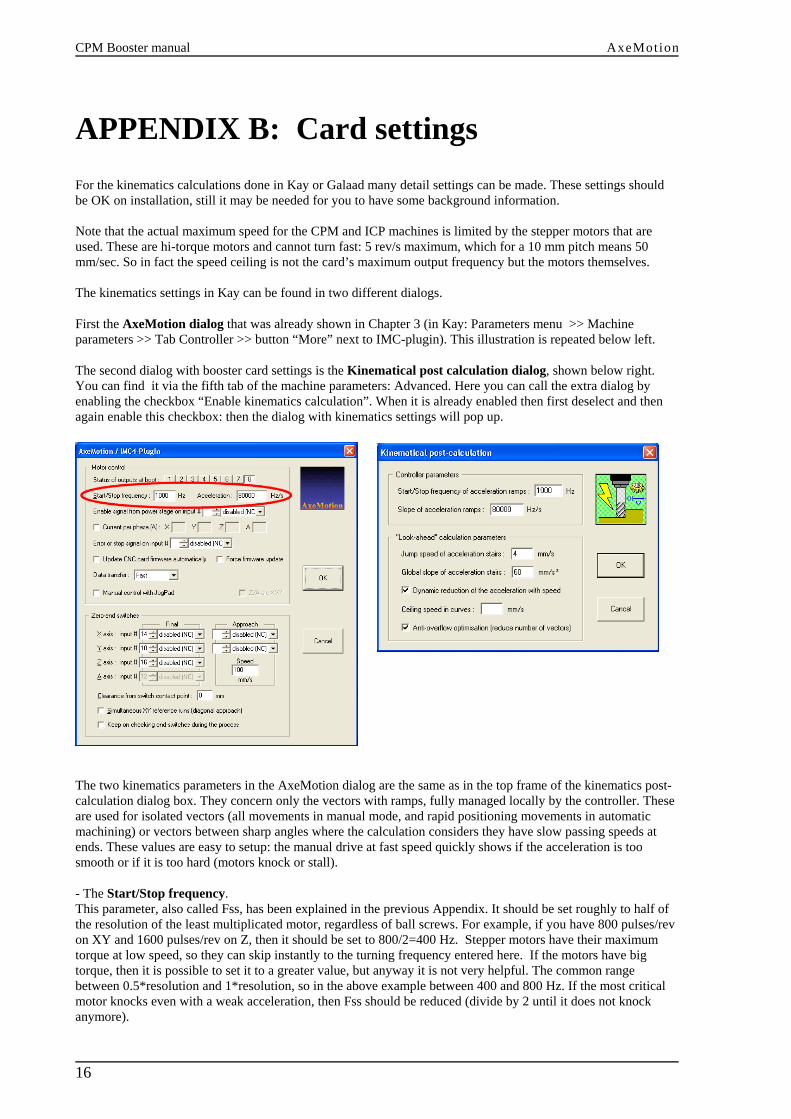
APPENDIX B: Card settingsFor the kinematics calculations done in Kay or Galaad many detail settings can be made. These settings shouldbe OK on installation, still it may be needed for you to have some background information.
Note that the actual maximum speed for the CPM and ICP machines is limited by the stepper motors that areused. These are hi-torque motors and cannot turn fast: 5 rev/s maximum, which for a 10 mm pitch means 50mm/sec. So in fact the speed ceiling is not the card’s maximum output frequency but the motors themselves.
The kinematics settings in Kay can be found in two different dialogs.
First the AxeMotion dialog that was already shown in Chapter 3 (in Kay: Parameters menu >> Machineparameters >> Tab Controller >> button “More” next to IMC-plugin). This illustration is repeated below left.
The second dialog with booster card settings is the Kinematical post calculation dialog, shown below right.You can find it via the fifth tab of the machine parameters: Advanced. Here you can call the extra dialog byenabling the checkbox “Enable kinematics calculation”. When it is already enabled then first deselect and thenagain enable this checkbox: then the dialog with kinematics settings will pop up.
The two kinematics parameters in the AxeMotion dialog are the same as in the top frame of the kinematics post-calculation dialog box. They concern only the vectors with ramps, fully managed locally by the controller. Theseare used for isolated vectors (all movements in manual mode, and rapid positioning movements in automaticmachining) or vectors between sharp angles where the calculation considers they have slow passing speeds atends. These values are easy to setup: the manual drive at fast speed quickly shows if the acceleration is toosmooth or if it is too hard (motors knock or stall).
- The Start/Stop frequency.This parameter, also called Fss, has been explained in the previous Appendix. It should be set roughly to half ofthe resolution of the least multiplicated motor, regardless of ball screws. For example, if you have 800 pulses/revon XY and 1600 pulses/rev on Z, then it should be set to 800/2=400 Hz. Stepper motors have their maximumtorque at low speed, so they can skip instantly to the turning frequency entered here. If the motors have bigtorque, then it is possible to set it to a greater value, but anyway it is not very helpful. The common rangebetween 0.5*resolution and 1*resolution, so in the above example between 400 and 800 Hz. If the most criticalmotor knocks even with a weak acceleration, then Fss should be reduced (divide by 2 until it does not knockanymore).

AxeMotion CPM Booster manual
17
On the CPM machine (1600 pulses/rev), Fss should thus be set to 800 Hz. The motors have a big torque and thevalue can be higher, but there is no need for it. On 4 mm screws, in theory this value can be increased a bit, inpractice the same value is used. In case the machine ‘knocks’ (makes funny noises) in manual drive then you canreduce in steps of 200. Note that for this test the manual speed has to be set on the maximum value.
- The Slope of Acceleration ramps.This is the slope from Fss to target speed, starting from the above-mentioned Fss frequency until the demandedspeed is reached (see Appendix A). If it is too high, then the motors stall (it will whistle) and refuse to turn (lose steps). If it is too low, then the motion is smooth and long: the machine will look heavy with soft accelerations.
On the CPM machine, the acceleration should be between 60000 Hz/s and 80000 Hz/s with 10 mm screws, andbetween 120000 - 160000 Hz/s with 4 mm screws. The AxeMotion card cannot perform accelerations of morethan 160 KHz/s, so it is useless to set it to a greater value.In case the Acceleration frequency is too high this may result in losing steps during high load conditions, youthen can try reducing to 75000 or even 50000. The manual drive says much in that matter, provided that you setthe motion speed to the highest value.
There is a function for calibrating these two parameters in the Galaad program: "Parameters / Machine /Calibrate". It gives good results for maximum speed and local ramp parameters, but of course it is more fuzzy onlook-ahead parameters because it cannot match all cases. Anyway the user should "listen to" his machine. Theear says a lot about motor knocks.
The bottom frame in the kinematics dialog box concerns the heart of the calculation, i.e. chaining vectors withoutramps along curves. These are in fact the settings for the look-ahead function, that adapts the speed to the shapeof the toolpath to come: high speed when paths will follow at low curvature, decelerate when a sharp corner isapproaching.
- The Jump speed of acceleration stairs.is the maximum gap that the most critical motor (the weakest or the one that drives the most loaded axis) canperform. It is given in speed units instead of Hz because the calculation applies on speeds, regardless of the gearfactors. The jump speed is the height of the speed stairs. If it is too high, the motors will lose steps; if it is toolow, there will be more vectors and the bandwidth will suffer.
On a CPM machine, I would set the jump speed to 4 mm/s with 10 mm screws, and 6 mm/s with 4 mm screws.Sorry the ratio is not linear.
- The Global slope of acceleration stairs.is the hardness of the acceleration, i.e. the angle of slope of the speed-curve / stairway. You can consider the toolis like a car in a crooked circuit: it must brake before a sharp corner and re-accelerate after. The global slope isthe capability to brake and accelerate. If it is too low, the acceleration will take long and the average speed willbe decreased; if it is too high, the motors will be unable to brake enough so steps will be lost in the curve.
On the CPM, acceleration slope should be about 60 mm/s². The torque of stepper motors decrease with speed, sothe acceleration capacity is not stable; it depends on the speed. Galaad / Kay integrates this is the kinematicsalgorithm, but unfortunately the decrease is not linear. There is a stall after a given speed which depends on themotor and the voltage it receives (the higher the better, since the coil gets its charge faster). With 4 mm screws,the slope can be set to 80 mm/s².
- Dynamic reduction of the acceleration with speed.This option makes the reduction of both jump speed and global slope depend on the path speed.The CPM motors cannot turn very fast and limit the maximum speed 50 mm/s with screws of 10 mm or 20 mm/swith screws of 4 mm. Faster is physically impossible for these motors. As the dynamic reduction option appliesto machines which run at 100 mm/s and above, it is not important for the CPM. Nevertheless by default it is setto Active.
- The Ceiling speed in curves.Parameter to avoid getting too fast in curves. When the maximum speed for the machine has been correctly setthis parameter can be ignored for CPM machines. The kinematics calculation is supposed to take care of thismaximum. So as default the edit box for this parameter is left blank.
- The Anti-overflow optimization.This option shortcuts mini-vectors which are not significant and only take bandwidth. A non significant vectormakes an angle of less than 3° with the previous one and has a small length. When the option is active, Galaad

CPM Booster manual AxeMotion
18
shortcuts vectors according to speed: a vector of 0.02 mm will be ignored at 10 mm/s, a vector of 0.1 mm will beignored at 50 mm/s (roughly). The vectors that are ignored cannot be longer than 1 mm and cannot make adirection change of more than 5°. Since on a CPM the maximum speed is only 50 mm/sec this option will not bevery useful for most NC files, still by default it is Active.
Conclusion:If you lose steps in manual drive, then reduce the Start/Stop frequency and possibly the Slope of acceleration. Ifyou lose steps during the milling process, then reduce the Jump speed and Global slope values.
Of course, if you use a machine that has more powerful motors or less inertia, then you can increase allkinematics parameters and consequently the actual machining time can be reduced a lot. If the kinematicsparameters are correct it should be impossible to go faster without losing steps. The CPM machine hashigh-torque motors that unfortunately cannot turn fast (and this is why they fit the machine with 10 mmballscrews), and their torque decreases a lot with speed, which ceilings the jump speed. Furthermore the axes ofthe machine are somewhat heavy. This is a good warranty for less vibrations when milling metal, but it requiresmuch torque to make the axes accelerate and decelerate. These machine characteristics set the maximum speedand acceleration that can be achieved, and are a match with the parameter settings mentioned above.
Racing car comparison:The best comparison for kinematics in a machine tool is a car in a racing circuit (this is simple 2D butexpandable to as many axes as you want), that car having exactly the same capabilities for accelerating andbraking. If a curve is sharp, then the car can run through it only at low speed. It must brake before and accelerateafter, the braking distance depending on the speed it had before the curve. If you think your curves are passed tooslowly, then yes the machine is slowing too much and that means the braking distance is too long. Increasing theSlope of acceleration parameter reduces the braking distance and the curve is entered faster. Of course, if it istoo high, the tool gets out of the path and this is a loss of steps. The value you have to find is the most powerfulacceleration that does not induce loss of steps. Of course it is better to keep a small margin so there are no risksof passing the limits. To test you can use a crooky path with some long straight lines and see if the machinemotion is not too hard nor too soft.
The above will be applied when you machine for instance a rectangle: four lines at 90 degree angles. Kay /Galaad will use classical vectors with ramps because begin- and end-speeds of a given vector are both under theStart/Stop frequency (Fss), and all kinematics is managed locally (by the controller card).
For a rectangle with rounded corners the speed at the end of the straight lines may be faster than the Start/Stopfrequency, and thus only vectors at constant speed may be used (so without ramps to Fss). Kay / Galaad will addvectors that make the stairs of an acceleration slope, the height of the stairs being the Jump speed which isactually a gap of frequency between two consecutive vectors. For the Axemotion card instead of a speed stairs aspeed curve can be used. Axes are no more considered together but one by one, because the X motor is notconcerned by the frequency gaps of the Y motor, etc. Like coordinates, we can split the tangent speed in speedcomponents for each axis, and any speed reduction for a motor has influence on the speed of other axes. This iswhere the calculation becomes tricky. The only thing that must absolutely be avoided is that one of the motorsmakes a speed jump higher than its capabilities. This would surely induce a loss of steps for that motor. Theadvantage of this approach is that it is valid whatever the number of axes.
In a few words: the acceleration slope parameter is the braking capability of the car, and the jump speedparameter the gap between two gears in the gear-box.

AxeMotion CPM Booster manual
19
APPENDIX B: Card specifications
Main characteristics of the AxeMotion CPM Booster card:• 4 Axis CNC module with USB interface, directly plugged on the IMC4 motherboard• USB powered for high-rate data transmission.• Up to 4 axis, with fast interpolation on 2, 3 or 4 axis simultaneously• Advanced kinematics possibilities• 35 KHz maximum output frequency• Look-ahead buffer (250 vectors)• Extension to 8 Inputs / 8 outputs (with an extension card)• One analog 0-10V output• Connector for AxMoBus extension • Compatible with Kay and Galaad.
The following Isel machine have the build-in IMC-4 controller and can be upgraded with this Booster card:• CPM 2018 / CPM 3020 / CPM 4030 • ICP2015 / ICP 3020 / ICP 4030.• GFM 4433

CPM Booster manual AxeMotion
20
For more information:
www.axemotion.com - Hardwarewww.galaad.net - Control Software
www.deskproto.com - 3D CAM software.