cpm 15v - carrs-tool.co.uk · cpm 15v cpm 15v cpm® 15v is the ultimate wear resistant grade in the...
TRANSCRIPT
Chemical CompositionC 3.4% Cr 5.3%
Mo 1.3% V 14.5%
CPM 15V
CPM 15VCPM® 15V is the ultimate wear resistant grade in the CPM® cold work steels family. The highest carbide amount of all PM cold work steels grant CPM® 15V an outstanding wear resistance and cutting edge stability with a reasonable toughness level. CPM 15V is recommended as the ultimate phase in tool performance improvement or as suitable alternative to solid carbide when higher toughness is required.
READYMILLED.COMRectangular sections from 25mm³ up to 430 x 430 x 150mm can be delivered fine milled on all six faces to -0+0.1mm and with squareness guaranteed to 0.1mm/m.
Typical ApplicationsBlanking and punching tools especially for thin sheets
Knives for electric steel sheet
Extrusion dies and hole punching tools
Knives for cutting foil, film and paper
Rotary cutters
Sinter pressing tools
Plastic forming tools where highly abrasive additives
are used
General items subject to wear
Modulus of elasticity E [GPa ] 235
Density [kg/dm³] 7.25
Coefficient of thermal expansion [mm/mm/K] over temperature range of 20 – 100 °C 20 – 250 °C 20 – 425 °C 20 – 600 °C
10.5 x 10⁻⁶
11.1 x 10⁻⁶
11.7 x 10⁻⁶
12.1 x 10⁻⁶
PHYSICAL PROPERTIES
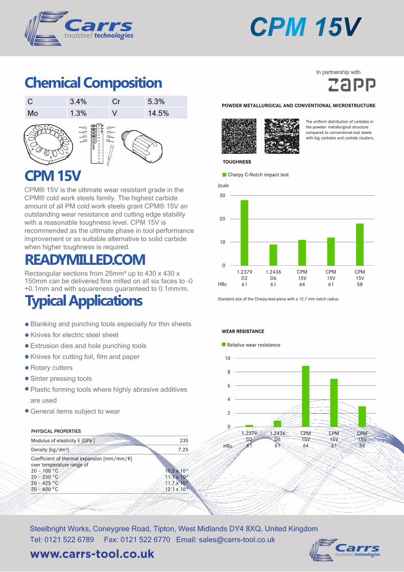
TOUGHNESS
Charpy C-Notch impact test
Standard size of the Charpy-test-piece with a 12.7 mm notch radius.
=
0
10
20
30
1.2379D261
1.2436D661
CPM15V64
CPM15V61
CPM15V58
Joule
HRc
WEAR RESISTANCE
Relative wear resistance
0
2
4
6
8
10
1.2379D261
1.2436D661
CPM15V64
CPM15V61
CPM15V58HRc
Steelbright Works, Coneygree Road, Tipton, West Midlands DY4 8XQ, United Kingdom Tel: 0121 522 6789 Fax: 0121 522 6770 Email: [email protected]
www.carrs-tool.co.uk
= POWDER METALLURGICAL AND CONVENTIONAL MICROSTRUCTURE
The uniform distribution of carbides in the powder- metallurgical structure compared to conventional tool steels with big carbides and carbide clusters.
In partnership with
QuenchingQuenching can take place in hot bath at 540°C, oil or pressurised gas. Quenching in salt bath or oil leads to maximum hardness, whereas cooling in vacuum can lead to lower values of 1-2 HRc. By use of vacuum quenching a minimum pressure of 6 bar is recommended. The appropriate pressure needs to be adjusted for complex tool shapes in order to minimise risk of cracking and tool distortion. For attaining ideal toughness properties, it is recommended to apply the hot bath quenching method. For attaining maximum hardness after quenching, the cooling rate between 1000°C and 700°C needs to be maximised.
TemperingTempering should be carried out immediately after the material has cooled down to below 40°C or when the tool can be held with hands. Triple tempering with a holding time of 2 hours in each stage at the tempering temperature of 550°C is necessary. It is important to ensure that the tools are cooled down to room temperature between the individual tempering stages.
Surface TreatmentsCPM 15V can be nitrided and/ or PVD/ CVD coated.
HEAT TREATMENTSoft AnnealingThe material is heated uniformly to a temperature of 870°C and then maintained at this temperature for 2 hours. Then, the material is cooled to 550°C in a furnace at a cooling rate of maximum 15°C per hour. It is then further cooled in still air down to room temperature. The typical hardness achieved by soft annealing is approximately 250-280 HB.
Stress RelievingRough machined material is stress relieved by heating to 600-700°C. Once complete heat penetration has been reached (minimum 2 hours), the material is allowed to cool in the furnace to approximately 500°C followed by cooling in air. Hardened material is stress relieved at 15-30°C for 2 hours below last tempering temperature followed by cooling in air.
StraighteningStraightening should be done in the temperature range of 200 to 430°C.
HardeningHardening of CPM® 15V usually involves the use of two preheating steps according to the table on the right. Depending on furnace and charging, additional preheat steps can be implemented. Maximum toughness is attained by austenitizing at 1070°C, whilst maximum wear resistance is attained by austenitizing at 1180°C. In order to achieve a corresponding degree of dissolution of the alloying elements, as well as an appropriate hardening, minimum heat penetration times as given in the table are recommended. These holding times should be correspondingly adapted for thick or thin-walled material cross sections.
CPM 15V
Steelbright Works, Coneygree Road, Tipton, West Midlands DY4 8XQ, United Kingdom Tel: 0121 522 6789 Fax: 0121 522 6770 Email: [email protected]
www.carrs-tool.co.uk
CPM 15V
545658
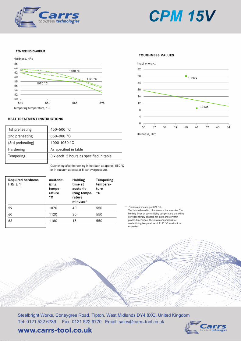
TEMPERING DIAGRAM
Hardness, HRc
66646260
565 595
1180 °C
1120°C1070 °C
5250
540 550
Tempering temperature, °C
HEAT TREATMENT INSTRUCTIONS
1st preheating 450–500 °C
2nd preheating 850–900 °C
(3rd preheating) 1000-1050 °C
Hardening As specified in table
Tempering 3 x each 2 hours as specified in table
Quenching after hardening in hot bath at approx. 550°C or in vacuum at least at 5 bar overpressure.
TOUGHNESS VALUES
0
4
8
12
16
20
24
28
32
56 57 58 59 60 61 62 63 64
Hardness, HRc
1.2379
1.2436
Imact energy, J
* Previous preheating at 870 °C. The data referred to 13 mm round bar samples. The holding times at austenitizing temperature should be correspondingly adapted for large and very thin profile dimensions. The maximum permissible austenitizing temperature of 1180 °C must not be exceeded.
Steelbright Works, Coneygree Road, Tipton, West Midlands DY4 8XQ, United Kingdom Tel: 0121 522 6789 Fax: 0121 522 6770 Email: [email protected]
www.carrs-tool.co.uk
Required hardness HRc ± 1
Austenit-izing tempe-rature °C
Holding time at austenit-izing tempe-rature minutes*
Tempering tempera-ture °C
59 1070 40 550
60 1120 30 550
63 1180 15 550
MACHINING DATA
CPM 15V
TURNING
Cutting parameter Turning with cemented carbide medium turning finish turning
HSS
Cutting speed (VC) m/min.
80-110 110-150 15-20
Feed (f) mm/U 0.2-0.4 0.05-0.2 0.05-0.3
Cutting depth (ap) mm 2–4 0.05-2 0.5-3
Tools according ISO
P 10-P 20* P 20* -
* Use wear resistant coated cemented carbide, e.g. Coromant 4015 or Seco TP 100.
=MILLING FACE- AND EDGEMILLING
Cutting parameter Milling with cemented carbide medium turning finish turning
HSS
Cutting speed (VC) m/min.
80-130 130-160 15
Feed (f) mm/U 0.2-0.3 0.1-0.2 0.1
Cutting depth (ap) mm 2-4 1-2 1-2
Tools according ISO
K 15* K 15* –
* Use wear resistant coated cemented carbide, e.g. Coromant 4015 or Seco TP 100.
=END MILLING
Solid carbide Milling cutter w. indexable tips
Coated HSS
Cutting speed (VC) m/min.
45-50 90-110 5-8
Feed (f) mm/U 0.01-0.20** 0.06-0.20** 0.01-0.30**
Tools according ISO
K 20 P 25*** -
* for TiCN-coated end mills made of HSS VC ∼ 25-30 m/min.
** depends on radial depth of cut and on milling cutter - diameter
*** Use wear resistant coated cemented carbide, e.g. Coromant 3015 or SECO T15M.
=DRILLING SPIRAL DRILL MADE OF HSS
Driller-∅ mm Cutting speed (VC) m/min.
Feed (f) mm/U
-5 10-12* 0.05-0.15
5 -10 10-12* 0.15-0.25
10 -15 10-12* 0.25-0.35
15 -20 10-12* 0.35-0.40
* for TiCN-coated end mills made of HSS VC ∼ 25-30 m/min.
=CARBIDE METAL DRILLER
Cutting parameter Drill type insert drill Solid carbide tip
Coolant bore driller with carbide tip*
Cutting speed (VC) m/min.
120-150 60-80 35
Feed (f) mm/U 0.08-0.14** 0.10-0.15** 0.10-0.20**
* driller with coolant bores and a soldered on carbide tip
** depends on driller-diameter
=GRINDING
Grinding method soft annealed hardened
Surface grinding, straight grinding wheels
A 13 HV B 107 R75 B3* 3SG 46 GVS** A 46 GV
Surface grinding A 24 GV 3SG 36 HVS**
Cylindrical grinding A 60 JV B126 R75 B3* 3SG 60 KVS** A 60 IV
Internal grinding A 46 JV B126 R75 B3* 3SG 80 KVS** A 60 HV
Profile grinding A 100 LV B126 R100 B6* 5SG 80 KVS** A 120 JV
* for these applications we recommend CBN-wheels
** grinding wheel from the company Norton Co.
Steelbright Works, Coneygree Road, Tipton, West Midlands DY4 8XQ, United Kingdom Tel: 0121 522 6789 Fax: 0121 522 6770 Email: [email protected]
www.carrs-tool.co.uk
In partnership with