cpd article - bidst
TRANSCRIPT

CPD Article ISSUE 11
Proud of our History, Looking Forward to the Future
CPD Article Issue 11.indd 1 07/12/2012 12:01

CPD Article Issue 11 | Page 2
This learning session has been judged as being equivalent to one hour of verifiable
CPD. To claim your verifiable CPD you will need to answer the questions at the end
of this article and submit them either by email to [email protected] or by post
to the BIDST Membership Office 44-46 Wollaton Road, Beeston Nottingham NG9
2NR. You will also need to keep a copy of the article together with your feedback
sheet and certificate for revalidation.BID
ST C
PD
Provided by:
Ref No. 36/10/01
Ultra Suction system increases the retention of mandibular complete dentures. Their retentive capacity in comparison to conventional dentures has been positively demonstrated via retention tests and clinical observation.(1)
A clinical study published in the EDA Journal, Jan. 2010 Vol.56, showed a significant improvement in the denture retention after the application of Ultra Suction system. The aim of this article is to familiarise the reader with the materials & methods through a comprehensive installation process.
Ultra Suction works on a simple mechanical principle: Suction. Two tiny one way valves imbedded into the lingual or palatal aspect of the denture base draw air from beneath the denture via two air channels, collectively open to a retention chamber.
As the wearer bites firmly, the air trapped between the mucosa and the denture is expelled through the
valves. Under negative atmospheric pressure, the diaphragms seal off the valve inlets. The pressure difference; that is, the lower pressure beneath the denture (2) (3) exerts a pull and draws the denture closer to the borders. The result is a better fit to the tissues and an improved resistance to dislodging forces.
The documented dental literature teaches us that the supporting soft tissue under a well crafted maxillary complete denture is subjected to -80mmHg of negative atmospheric pressure. This is the suction level experienced by upper denture wearers (4).Ultra Suction valves have been developed to generate the same negative force when applied to mandibular dentures or to palateless
maxillary dentures.
The system is commercialised as a full kit with illustrated mounting instructions. The components may be used for either upper or lower dentures, on completely new dentures or fitted on existing dentures during the reline/ rebase procedure.
System Components
The spacer Bar is used to create a retention chamber. Made of malleable metal, the bar is designed to sit intimately against the ridge. It can be easily bent, burnished and adapted to almost any alveolar ridge.
Valves Two one way valves designed to expel the air beneath the dentures. The central hole in the valve body is described as the inlet and the valve cover as the exhaust.
Ultra Suction™ Denture Stabiliser System Materials & Methods
Authored by Mony Paz and Ted J. Carson
CPD Article Issue 11.indd 2 07/12/2012 12:01

CPD Article Issue 11 | Page 3
Processing Caps. As their names suggest, the caps are fitted onto the valve bodies before the installation procedure. Their role is to protect the valves. They are removed only after the polishing phase.
Diaphragms Two diaphragms and two spares come with the kit. These tiny plastic discs seal the inlet under negative atmospheric pressure and release the pressure under resting conditions, at the rate of 10mmHg per 15sec.
Service key has two extremities. The upper part is used to grip, close & open both the valve covers and the processing caps. The lower part is a slightly larger replica of the valve and may be used as a gauge for depth and diameter.
Ultra Suction Technique
The popular proverb “a picture is worth a thousand words” attributed to Confucius is certainly the philosophy adopted by the Korean Academy of Dental Technology. In his clinical and technical papers, Associate Professor Yi Cheong Jae aptly reinforces one of the main goals of visualisation, namely making it possible to absorb large amounts of data quickly. This display of some interesting shots takes us through the installation process (5) starting with two light-body vinyl polysiloxane impressions loaded on special trays: Fig.1. The impressions were boxed, with particular attention to preserving accurate borders and to encompass the tuberosity protuberances: Fig.2
Yellow stone was used to pour the casts from the impressions and after setting, the cast models were trimmed Fig.3-4.
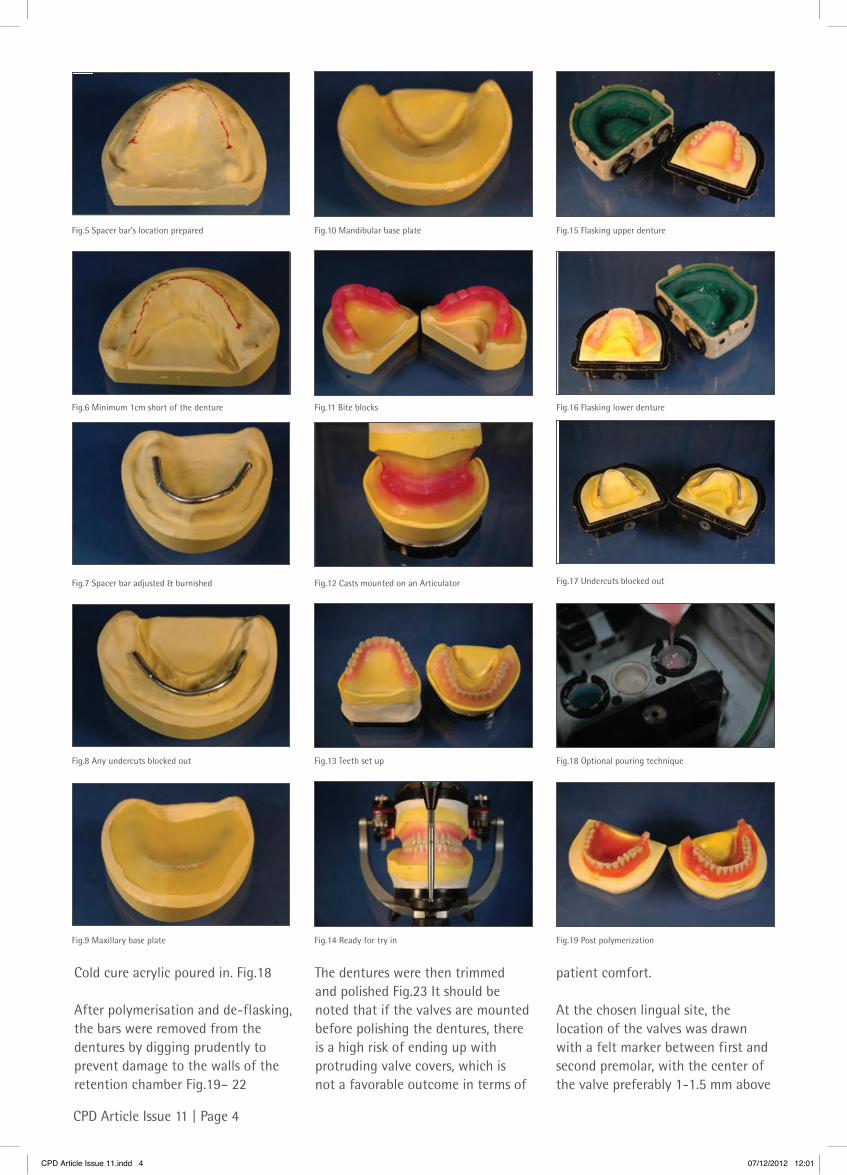
On the ridge, the location of the spacer bar was pencil designed, making sure that the bar stopped at least 1cm short of the end of the denture: Fig.5 - 6. The bar was stabilised using 2-3 small drops of cyanoacrylate and any undercuts were blocked-out. Fig.7 -8
Hard base plates were prepared on top of the spacer bars Fig.9-10 followed by bite blocks Fig.11. After bite registration, the casts were mounted on an articulator Fig.12 and teeth set-up for try-in was carried out Fig.13-14
In this case study, the Agar flasking technique and cold cure acrylic were used. However, all other flasking and packing techniques are acceptable.
Each model (cast) was packed in a two part flask Fig.15-16. The spacer bar remained on the model and any undercuts were blocked out Fig.17.
Fig.1 Vinyl Polysiloxane Impressions
Fig.3 Impressions poured
Fig.2 Boxed Impressions
Fig.4 Casts are trimmed
CPD Article Issue 11.indd 3 07/12/2012 12:01
CPD Article Issue 11 | Page 4
Cold cure acrylic poured in. Fig.18
After polymerisation and de-flasking, the bars were removed from the dentures by digging prudently to prevent damage to the walls of the retention chamber Fig.19– 22
The dentures were then trimmed and polished Fig.23 It should be noted that if the valves are mounted before polishing the dentures, there is a high risk of ending up with protruding valve covers, which is not a favorable outcome in terms of
patient comfort.
At the chosen lingual site, the location of the valves was drawn with a felt marker between first and second premolar, with the center of the valve preferably 1-1.5 mm above
Fig.9 Maxillary base plate
Fig.11 Bite blocks
Fig.14 Ready for try in
Fig.10 Mandibular base plate
Fig.13 Teeth set up
Fig.12 Casts mounted on an Articulator
Fig.15 Flasking upper denture
Fig.17 Undercuts blocked out
Fig.16 Flasking lower denture
Fig.18 Optional pouring technique
Fig.5 Spacer bar’s location prepared
Fig.7 Spacer bar adjusted & burnished
Fig.6 Minimum 1cm short of the denture
Fig.8 Any undercuts blocked out
Fig.19 Post polymerization
CPD Article Issue 11.indd 4 07/12/2012 12:01

CPD Article Issue 11 | Page 5
Fig.29a Processing Cap
Fig.28 Housing for valves completed
Fig.27 Depth and diameter checked
Fig.26 Housings prepared for the valves
Fig.30 Try in Valve
Fig.29b Mounted on the valve
Fig.21 Bars carefully removed
Fig.22 Retention chamber obtained
Fig.23 Dentures trimmed & polished
Fig.24 Location for valves marked
Fig.25 1-1.5 mm above retention chamber
Fig.20 Deflasking
the highest point of the retention chamber. Fig.24-25
The cavities for the valves were prepared with a round bur Fig.26 intermittently using the gauge side of the service key for guidance i.e.. depth and diameter Fig.27-28.
Processing caps were then placed in the valves to protect the core from being filled with self cure acrylic and then tried in. Fig.29a -30
The valves were installed with cold cure acrylic Fig.31-32. Soft rubber cylinder points were used to remove
excess material and to polish around the valves Fig. 33. The dentures were given a final sheen Fig.34
The processing caps were removed and the valve body inspected Fig.35-36
Using a 1mmØ fissure a communication channel was created between the valve and the high point of the retention chamber Fig.37-38. For dentures with a significant thickness of acrylic between the valves and the retention chamber, drilling is done on an obtuse angle.
Each valve was rinsed and dried thoroughly to ensure a smooth placement of the diaphragm into its housing Fig.39-40. The perforated cover was fitted and tied up using the service key. Fig.41-43
Discussion
Ultra Suction system appears to increase considerably the retention of complete dentures in both clinical observation and in statistical findings. Their retentive capacity is superior to that of conventional dentures.(1) The decrease in the rate of applied negative force by
CPD Article Issue 11.indd 5 07/12/2012 12:01

CPD Article Issue 11 | Page 6
Fig.41 Perforated cover engaged in valve
Fig.43 Using the service key provided
Fig.42 Cover tied up
Fig.31 Small amount of self cure acrylic
Fig.33 Excess removed and trimmed
Fig.35 Processing caps removed
Fig.37 Communication channel through valve
Fig.39 Valve rinsed and dried
Fig.32 Valve inserted in stages
Fig.34 Dentures given final sheen
Fig.36 Valve body inspected
Fig.38 Joined via retention chamber
Fig.40 Diaphragms placed in their housing
10mmHg per 15sec., attributed to the design of the diaphragms, suggests that we may have a more tissue friendly denture than we first thought. It is well known that the supporting tissue is subject to -80mmHg under conventional maxillary dentures, which caused an
increase in epithelial width in the palate and attached gingiva, and a decrease in epithelial width in the alveolar mucosa (4) in most, if not all, complete denture wearers. This response is directly related to the functional demands of the tissue. In view of this documented evidence,
it would be reasonable to conclude that Ultra Suction’s negative force is less invasive than that of conventional dentures.
CPD Article Issue 11.indd 6 07/12/2012 12:01
CPD Article Issue 11 | Page 7
References:
1. Badra SH, Radi I, Aboulela A et al. The effect of ultra suction system on the retention of mandibular complete denture. EDJ Vol.56, 101:109, January 2010
2. Rahn AO, Heartwell CM. Textbook of complete denture. [5th ed.] BC Decker Inc., Hamilton, London,2002:227.
3. Zarb GA, Bolender CL, Carlsson G.
Boucher’s prosthodontic treatment for edentulous patients. [11th ed.] St.Louis C.V. Mosby, 1997: 460-468
4. Grossman ES, Forbes ME. Studies related to reaction of supporting soft tissue to denture wear: the histological response of vervet monkey oral epithelium to a -80 mmHg vacuum. J Oral Rehabil. 1990 Nov;17(6):587-97.
5. Yi -Cheong Jae. Ultra-Suction
Denture, Journal of Korean Academy of Dental Technology Vol.29 No2.
For more information contact:
Abacus Dental Tel: +44 (0)1274 735244 Email: [email protected]
Provided by:
CPD Questions Ref No. 36/10/01
“To claim your verifiable CPD you will need to answer these questions and submit them either by email to [email protected] or by post to the BIDST Membership Office 44-46 Wollaton Road, Beeston Nottingham NG9 2NR. You will also need to keep a copy of the article together with your feedback sheet and certificate for revalidation”.
Q1) What is used to draw air from beneath the denture via two channels, collectively open to a retention chamber and where are they placed?
Q2) Under what atmospheric pressure do the diaphragms seal off the valve inlets?
Q3) What is the result of the pressure difference i.e. the lower pressure beneath the denture exerts a pull and draws the denture closer to the borders?
Q4) The system is commercialised as a full kit with illustrated mounting instructions. What type of dentures can the components be used on?
Q5) The spacer bar is made from malleable metal and is designed to sit intimately against the ridge however what is it used to create?
Q6) After what process were the cast models trimmed?
Q7) How was the spacer bar stabilised?
Q8) After polymerisation and de-flasking, the bars were removed from the dentures by digging prudently, by completing the process what is hoped to be prevented.
Q9) As the chosen lingual site, the location of the valves was drawn with a felt marker between the first and the second premolar. At what measurement was the centre of the valve preferably above the highest point of the retention chamber?
Q10) What types of burs were used to remove the excess material and to polish the valves?
Postcode:
Telephone no: (in case of any queries)
Signed:
Date:
Name:
GDC Number
Address:
CPD Article Issue 11.indd 7 07/12/2012 12:01

British Institute of Dental & Surgical Technologists44-46 Wollaton Road,
Beeston,
Nottingham
NG9 2NR
Telephone: +44(0)115 968 3181
Fax: +44(0)115 925 4800
Website: www.bidst.org
Email: [email protected]
CPD Article Issue 11.indd 8 07/12/2012 12:01