coversheet - idaho national laboratory
TRANSCRIPT

LA-UR-20-20824Approved for public release; distribution is unlimited.
Title: Microreactor Agile Nonnuclear Experimental Testbed Test Plan
Author(s): Trellue, Holly ReneeO'Brien, JamesReid, Robert StowersGuillen, DonnaSabharwall, Piyush
Intended for: Report
Issued: 2020-01-29 (rev.1)

Disclaimer:Los Alamos National Laboratory, an affirmative action/equal opportunity employer, is operated by Triad National Security, LLC for the NationalNuclear Security Administration of U.S. Department of Energy under contract 89233218CNA000001. By approving this article, the publisherrecognizes that the U.S. Government retains nonexclusive, royalty-free license to publish or reproduce the published form of this contribution,or to allow others to do so, for U.S. Government purposes. Los Alamos National Laboratory requests that the publisher identify this article aswork performed under the auspices of the U.S. Department of Energy. Los Alamos National Laboratory strongly supports academic freedomand a researcher's right to publish; as an institution, however, the Laboratory does not endorse the viewpoint of a publication or guarantee itstechnical correctness.

Microreactor Agile Nonnuclear Experiment Testbed Test Plan Holly Trellue^, James O’Brien*, Robert Reid^, Donna Guillen*, Piyush Sabharwall*
^Los Alamos National Laboratory *Idaho National Laboratory

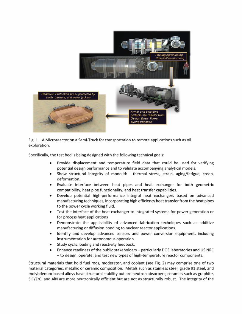
1.0 Introduction Microreactors are an attractive technology option for kick-starting nuclear innovation if they can be operated at high temperature, yielding high power conversion thermal efficiencies comparable or better than in commercial light water reactors. Microreactors are currently the smallest variation of Small Modular Reactors (SMRs). SMRs are “newer generation reactors designed to generate electric power up to 300 MWe and whose components and systems can be shop-fabricated and then transported as modules to the sites for installation as demand arises.” (IAEA, 2016). Vendors are developing microreactor designs to provide an affordable, potentially mobile source of electricity - see Fig. 1 for an example of a microreactor on a semi-truck. Various microreactor designs are possible including heat pipe- and gas-cooled options, which are the focus of the nonnuclear testing described in this document. In heat pipe microreactors, high-temperature heat pipes using liquid sodium or potassium working fluid transport fission heat from the core to a heat removal section which in turn transfers heat to the power conversion system working fluid. In a gas-cooled design, He or other gas will flow through a solid monolith of material and transfer heat as the temperature of the gas increases through a heat exchanger to a power conversion unit. The logistics of all these processes will be examined and tested through a series of articles at the nonnuclear test bed at Idaho National Laboratory (INL), the Microreactor Agile Nonnuclear Experiment Testbed (MAGNET) facility.
Microreactors designed to produce power of 0.1-20 MWt offer the potential for more affordable nuclear energy for a range of applications. In a heat pipe microreactor, heat pipes, fuel rods, and/or moderator are intermixed in the reactor core assembly. Heat pipes extend from the core region into the heat removal section where the power conversion unit working fluid flows through holes or channels, transferring heat from the heat pipes to the working fluid. In a gas-cooled microreactor, gas flows through the solid monolith region and up into the heat exchanger region, transferring heat to the working fluid. For initial testing, the heat removal working fluid can be a low pressure gas for testing that addresses thermal stresses. In the final application, heat addition to the power conversion working fluid typically occurs at high pressure, supporting operation of an air-Brayton, supercritical CO2 (SCO2), or He-recuperated Brayton cycle. Various stages of the steps above will be demonstrated through the tests described in this report.
2.0 Background Microreactors are attractive for various reasons: they are transportable, economic, and capable of higher temperatures and power conversion thermal efficiencies than commercial reactors, etc. If operated at high temperatures (> 600°C), micro reactors are capable of achieving 32 % thermal efficiency for power production or, possibly higher for a supercritical CO2 Brayton cycle. Both gas-cooled and heat pipe-cooled microreactor designs are being examined and will be tested at the nonnuclear test bed, MAGNET facility.
As part of the DOE-NE Microreactor program, MAGNET will provide a location for laboratories and vendors to test technology excluding fuel to advance the technical maturity of this new type of nuclear reactor in an approved environment. This technology includes but is not limited to: monolith materials, heat pipes or gas coolant, heat exchangers, power conversion units, instrumentation and sensors, and/or moderating material. Both gas- and heat pipe-cooled nonnuclear test units will be built and tested. Success is defined as testing the performance of relevant components operating under prototypical conditions to ensure safe operation of the reactor.
Specifically, the test bed is being designed with the following technical goals:
• Provide displacement and temperature field data that could be used for verifying potential design performance and to validate accompanying analytical models.
• Show structural integrity of monolith: thermal stress, strain, aging/fatigue, creep, deformation.
• Evaluate interface between heat pipes and heat exchanger for both geometric compatibility, heat pipe functionality, and heat transfer capabilities.
• Develop potential high-performance integral heat exchangers based on advanced manufacturing techniques, incorporating high efficiency heat transfer from the heat pipes to the power cycle working fluid.
• Test the interface of the heat exchanger to integrated systems for power generation or for process heat applications
• Demonstrate the applicability of advanced fabrication techniques such as additive manufacturing or diffusion bonding to nuclear reactor applications.
• Identify and develop advanced sensors and power conversion equipment, including instrumentation for autonomous operation.
• Study cyclic loading and reactivity feedback. • Enhance readiness of the public stakeholders – particularly DOE laboratories and US NRC
– to design, operate, and test new types of high-temperature reactor components.
Structural materials that hold fuel rods, moderator, and coolant (see Fig. 2) may comprise one of two material categories: metallic or ceramic composition. Metals such as stainless steel, grade 91 steel, and molybdenum-based alloys have structural stability but are neutron absorbers; ceramics such as graphite, SiC/ZrC, and AlN are more neutronically efficient but are not as structurally robust. The integrity of the
Fig. 1. A Microreactor on a Semi-Truck for transportation to remote applications such as oil exploration.

monolith with various materials is still being examined. A non-solid core containing other material is also an option. Structural materials in microreactors serve three purposes:
1) they assure that reactor heat can be removed from the core geometry during normal, abnormal and accident scenarios (including for example during conduction-assisted passive cool-down);
2) they act as barriers to fission products to retain them within the core ‘vessel’ at all times; and
3) they assure that geometry-influenced reactivity temperature coefficient (RTC) is repeatable and predictable.
To achieve the functionality in the numbered items above, structures need to be constructed of thermal creep-resistant and corrosion-resistant materials. Given high temperature in-service conditions, no single material can achieve these objectives. Stainless steels 304/316 and Inconel 617 are robust, well-known materials, but stainless steel in particular cannot be operated above about 600°C. Nevertheless, because stainless steel 316 is well-known and proven, it has been selected as the solid monolith material in the first two test articles as will be described below. Grade 91 stainless steel is being examined as a better alternative for reactors but still is constrained with a maximum temperature of 600°C. Additionally, refractory metal alloys such as titanium-zirconium-molybdenum (TZM) and molybdenum-niobium (Mo1%Nb) can easily withstand high temperatures and large thermal stresses but are known to be vulnerable to recrystallization during thermal cycling stress relief and to oxidize when exposed to even trace quantities of oxygen or water vapor. Similarly, ceramics and ceramic composites such as graphite, SiC, and ZrC have the ability to operate at high temperatures while also serving as a neutron moderator, allowing for reduced fuel mass. Graphite materials have been examined in the past, and research both on irradiation properties and their compatibility with heat pipes is on-going. Borated graphite, SiC, and ZrC require additional testing. These ceramic materials have matured significantly but may still require metal backup or structure within the monolith to maintain ductility. Advanced coatings and additive manufacturing methods exist to overcome these drawbacks but only on a case-by-case basis. Not surprisingly, the Microreactor industry is adapting different materials and fabrication methods for fabricating core internals.
Other materials under consideration for use in microreactors (see Fig. 3) include:
• Gas Coolant: – Gas is a poor heat conductor, so hots spots in the core and heat exchanger need to be
examined to flatten the power distribution radially and axially. – Measure thermal expansion as a function of temperature (esp if fabricated by additive
manufacturing). • Moderator:
– Purpose is to increase neutron efficiency and decrease fuel mass. – Yttrium hydride (YHx=1.5-2) material performs well. – Zirconium hydride is less expensive but loses hydrogen at high temperatures, so a
combination of the two may be desired. – Positive predicted reactivity coefficients may drive need for another additive.
• Reflector: – Beryllium oxide (BeO) or Magnesia (MgO) are ideal but expensive. – Alumina (Al2O3) is less expensive. – Temperature limits on a reflector such as Be need to be tested.
• Fuel: – Metal Uranium Molybdenum Alloy (U-10 Moly) or Zirconium alloy fuel with 19.75%
enrichment exists at Y-12 but has low melting temperature.

– Uranium Oxide (UO2) with enrichment up to 5% is commonly manufactured but is associated with high melting temperatures and low conductivity.
– Uranium Nitride has high conductivity and melting temperature, but neutron capture occurs in N-14. Wider spread fabrication capabilities are being examined.
– Tristructural-isotropic (TRISO) particle fuel offers the advantage of containing all fission products but still requires technological development and testing for final use.
• Cladding types are primarily being examined/tested separately from this microreactor program.
Fig. 2. Example microreactor monolith geometry.
Heat pipes Fuel
Control Rod
Fig. 3. Example of Microreactor unit with fuel, heat pipes, moderator rods, and monolith.
Fuel
Heat Pipe Moderator
Monolith

3.0 Description of Proposed Tests
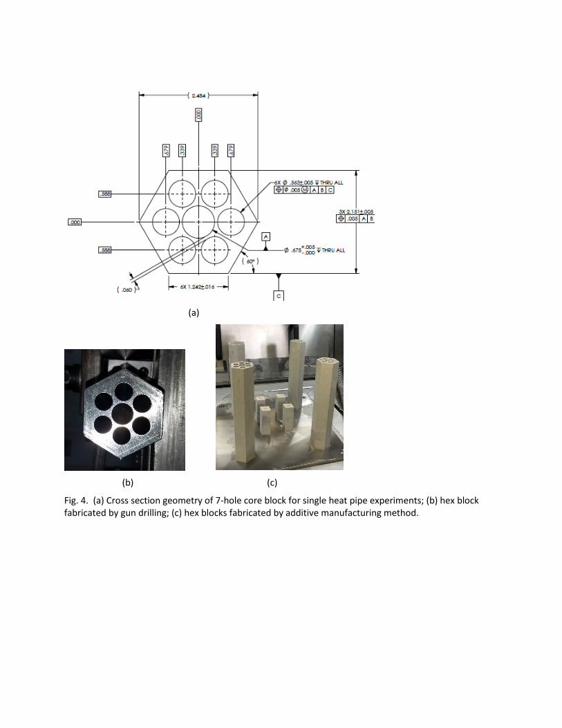
The INL Microreactor AGile Nonnuclear Experimental Testbed (MAGNET) is being designed to support prototypical non-nuclear microreactor testing up to the 250 kW scale. Test articles that are both heat pipe- and gas-cooled will be fabricated and demonstrated as summarized in Table 1. Table 2 expands upon Table 1 to describe more specifics about the range of all technology that could be included in the nonnuclear tests. Smaller test articles comprise a 7 hole block with the purpose of demonstrating structural integrity and other basic functionality. The initial test article will be a single heat pipe experiment in a 7 hole block of stainless steel with six heaters in holes surrounding the 75 kW electrically heated heat pipe reactor subassembly (see Fig. 4). The subassembly core will be heated using conventional electrical resistance cartridge heater as one of the goals of the test is to understand heat pipe performance better.
However, larger test articles are required to test heat transfer/heat exchanger functionality. The second test article includes 37 high-temperature sodium-filled heat pipes that extend from the core to the heat removal section (see Fig. 5). The heaters can be operated up to 760°C sheath temperature. The heat pipe nominal operating temperature is 650°C. In order to minimize the temperature drop across the gap between the heaters and the core block, good thermal coupling must be achieved. One of the objectives of the single heat pipe experiments is to determine the most effective method to minimize the thermal resistance between the heaters and the core block and also between the core block and the heat pipes. Additional test objectives include heat pipe characterization in terms of operating temperature as a function of heat transfer rate. We will also be interested in measurement of axial temperature profiles along the length of the evaporator section using thermal imaging and surface-mounted thermocouples.
Table 1. Summary of Potential Nonnuclear Demonstrations
Structure Heat transfer Type of Demonstration
Stainless steel Heat pipe 1) 7 hole, single heat pipe, six heaters
2) multiple 7 hole test articles with gaps between units
3) 37 heat pipe/heater/ heat exchanger
4) Power Conversion Unit (PCU)
Graphite Gas-cooled (mainly) 1) 7 hole monolith
2) Heater/heat exchanger
3) Power Conversion Unit
Molybdenum Heat pipe 7 hole, single heat pipe
ZrC or SiC Gas-cooled? 7 hole monolith
Liquid Heat pipe Single/multiple heat pipes

Table 2. Proposed Nonnuclear Tests
7 Hole Article – Stainless Steel
37 heat pipe article – stainless steel
Determine effect of gaps between heat pipes
Other monoliths including: graphite, Mo, ZrC/SiC, and/or liquid
Preliminary testing of cartridge heaters, power control and measurement, calorimetry, and thermal coupling of heaters to core block using a water-cooled simulated single heat pipe test apparatus
Test block with 37 heat pipes and integral heat exchanger.
Perform test with multiple 7 hole test articles near each other but different amounts of space between them.
Test heat pipe operation with cartridge heaters up to 750° C and analyze results
Determine integrity of stainless steel monolith and welds/bonds used during fabrication
Characterize heat transfer from heat pipes to heat exchanger and assess thermal output.
Analyze effect of gas gap.
Determine structural integrity and bonding/welding integrity.
Apply DIC test method on single heat pipe
Potentially analyze failed heat pipe situation and/or other accident scenarios.
Gas reactor tests Evaluate creep, stress, and/or bowing in structural material
Advanced heat exchanger test
Instrumentation and Sensors
Test block with gas coolant for ability to produce thermal output evenly throughout the core.
Power Conversion Unit (PCU)
Operate advanced heat exchanger with low-pressure air coolant to determine heat transfer/ stress/performance.
Analyze performance of control drums outside (yet separate from) a test article.
Characterize heat transfer to heat exchanger and/or PCU
Characterize heat transfer from heat exchanger to PCU (from either 37 heat pipe and/or advanced heat exchanger articles).
Operate advanced heat exchanger with high-pressure nitrogen coolant to determine heat transfer and thermal stress performance.
Evaluate advanced temperature sensing methods on single heat pipe
Advanced Moderator Tests - Fill several heater holes with YH
x.
Determine how much power can be derived from PCU.
Test condenser side and document heat transfer as a function of length.
Evaluate creep, stress, and/or bowing in structural material
Evaluate stability/integrity of moderator material.
(a)
(b) (c)
Fig. 4. (a) Cross section geometry of 7-hole core block for single heat pipe experiments; (b) hex block fabricated by gun drilling; (c) hex blocks fabricated by additive manufacturing method.

Fig. 5. Cross section geometry of 37 heat pipe core block, picture of two 37 heat pipe stainless steel core blocks fabricated with additive manufacturing, and diagram of core block and heat exchanger parts to be fabricated.
Core
Heat Exchanger
Tube sheet
Cap
Heat Pipes
eFill Interface

4.0 Specifics of Initial Proposed Tests Two main test articles are currently being built for demonstration in the nonnuclear test bed and will be described in the next two sections. Plans for other types of tests are discussed thereafter. 4.1 Single Heat Pipe Experiments The first test article that will be examined is a 7-hole design with 6 cartridge heaters fitted into the 6 outer holes and a single heat pipe in the center of a solid monolith block of stainless steel 316L (see Fig. 4). Several different versions/lengths of this test article are being fabricated using both traditional and additive manufacturing methods, as shown in Fig. 4 (b) and (c). The purpose of these tests is to characterize the performance of a single heat pipe in a monolithic configuration with well-defined thermal boundary conditions for both transient and steady-state operation. The structural integrity of the test article will also be examined. Table 3 describes the specific tests that are planned.
Sodium heat pipes for these tests are being acquired from two sources: Advanced Cooling Technologies (ACT) and Los Alamos National Laboratory (LANL). The body of these heat pipes will be stainless steel. The working fluid is sodium and the wick structure will be specific to the supplier. The total quantity of sodium in each heat pipe is small, ~60 - 80 gm. After charging, the heat pipes are welded shut. From the standpoint of our operations, the heat pipes are fully closed/fully sealed test articles that will be operated within their design limits. We will not be doing any direct handling of sodium as part of this work. As noted previously, pressure inside the heat pipes will be sub-atmospheric even at their highest operating temperature, so any failure of the heat pipe would not involve a pressurized release of material.
The cartridge heaters to be used in this test have internal thermocouples for monitoring their centerline operating temperature. Heater power control is achieved using SCR-based power controllers (Watlow Din-A-Mites), based on a 4-20 mA control signal provided from the data acquisition system (National Instruments SCXI System) which is interfaced to a Labview virtual instrument for data acquisition and instrument control. Power to each heater is monitored continuously using precision power meters designed for measurement of SCR-controlled loads. The heaters can be operated up to 760°C. Exposed hot surfaces are a safety consideration for these tests and appropriate briefings and signage will be used to mitigate this hazard. In some cases, the hot surfaces will have to be exposed in order to allow for quantitative thermal imaging.
The design basis heat flux value for the cartridge heaters is 3.8 W/cm2, based on expected microreactor core power densities. For the 6-inch block, this power density yields 317 W per heater and a total power of 1891 W, and for the 1 m block, each heater would operate at 2 kW for a total power of 12 kW with linear interpolations between the two. However, since there is only one heat pipe, with a total heat removal rating of 2 kW for the LANL heat pipe; 1 kW for the ACT heat pipes, the heat fluxes that will be applied during testing will be limited by the heat transfer rating of the heat pipes. This limitation will result in the use of significantly lower heat fluxes than the full prototypical core design values for the longer core blocks. Heat pipe operating temperatures will be limited to 750°C. Note that the vapor pressure of sodium is still well below 1 atm at this temperature. Therefore, over-pressurization failure of the heat pipe is not a safety consideration.
The heat pipes will be operated in an inert gas environment consisting of either helium or a helium-argon mixture. Therefore, the single heat pipe experiments will be performed using the test fixture shown in Fig. 6. The entire heat pipe assembly will be housed in a cylindrical inert-gas environment formed by a quartz tube with flanges on either end to allow for inlet and outlet gas flows as well as feedthroughs for instrumentation and power. The quartz tube will allow for visual observation of heat pipe operation and quantitative thermal imaging. The quartz also provides containment in the unlikely event of a leak of sodium from the heat pipe.

Table 3. Proposed Testing of 7-hole stainless steel heat pipe test articles
Preliminary testing of cartridge heaters, power control and measurement, calorimetry, and thermal coupling of heaters to core block using a water-cooled simulated single heat pipe test apparatus with a 7-hole core block
Single ACT heat pipe tests with 7-hole core blocks of different lengths; characterize low-power heat pipe performance during startup and at steady-state conditions; thermal imaging of transient heat pipe operation; test under both vacuum and inert gas conditions
Single ACT heat pipe tests with 7-hole core blocks of different lengths; characterize high-power heat pipe performance during startup and at steady-state conditions; perform calorimetric measurements with water-cooled gas gap calorimeter; determine heat pipe operational limits
Single LANL heat pipe tests with 7-hole core blocks of different lengths; characterize low-power heat pipe performance during startup and at steady-state conditions; thermal imaging of transient heat pipe operation; test under both vacuum and inert gas conditions
Single LANL heat pipe tests with 7-hole core blocks of different lengths; characterize high-power heat pipe performance during startup and at steady-state conditions; perform calorimetric measurements with water-cooled gas gap calorimeter; determine heat pipe operational limits
For full-power heat pipe operation, an effective heat removal system is required. A detailed drawing of the planned heat pipe cooling section is provided in Fig. 7. The condenser end of the heat pipe will be surrounded by a water-cooled shroud as shown in the figure. Water cooling is necessary to provide sufficient heat removal to support the full 2 kW heat transport rating of the LANL heat pipe. There will be no direct contact of water with the heat pipe test article. The water flow system will be fully leak-checked prior to placement of the heat pipe into the apparatus. The heat pipe will be inserted into the center ¾-inch tube that is open on both ends. A wire wrap will be used to center the heat pipe inside of the tube. The gap between the heat pipe and the ¾-inch cooling tube will be filled with inert gas. So the heat removal system acts as a gas gap calorimeter. Heat transfer from the heat pipe to the inside surface of the ¾-inch tube will occur by a combination of radiation plus conduction. Conduction is the dominant mode. The magnitude of the conduction heat transfer can be reduced as needed by introducing Ar gas into the gap in addition to or instead of He. The length of the cooling shroud can also be reduced to achieve the optimum heat pipe operating temperature and maximum rated heat transfer.
Fig. 6. Single heat pipe test fixture.

Fig. 7. Detail of heat pipe cooling section.
Thermocouples may be spot-welded to the outside surface of the heat pipes. These thermocouples will have to be removed to fit the heat pipes into the core block and the cooling shroud. A process flow diagram for the single heat pipe experiment is provided in Fig. 8. Cooling water will be recirculated using a 2.5 kW circulating chiller unit, so there will be no significant net water usage. The water flow loop includes a precision turbine flow meter and a delta-T meter that will allow for accurate determination of the heat removal rate from the heat pipe to the cooling water. Prior to testing, the quartz tube will be evacuated using a vacuum pump and then back-filled with inert gas (He or Ar). This process will be repeated several times (successive dilution) at the beginning of each test to ensure that all the air has been removed. The objectives of the single heat pipe testing are:
• Documentation of heat pipe thermal performance under a wide range of heating values and operating temperatures.
• Observation and documentation of heat pipe startup and transient operation.
• Development of effective thermal coupling methods between the heat pipe outer surface and the core block and between the cartridge heaters and the core block.
• Measurement of heat pipe axial temperature profiles during startup, steady-state, and transient operation using thermal imaging.
Thermal performance of the operating heat pipes will be determined by measurement of heat pipe heat removal capacity as a function of operating temperature. The heat removal rate will be equal to the total heater electrical power input, measured by the power meters, minus any heat losses as determined by a combination of measurements and analysis. Startup and transient behavior will be measured by acquisition of time-dependent temperature response data of the whole system including the heaters, the core hex block, and the heat pipe. The effectiveness of the thermal coupling technique between the heaters and the core block and between the heat pipe and the core block will be determined by measurement of the heater temperatures, core block temperature, and heat pipe temperature over a range of operating conditions. Ideally the outer sheath of the heaters should have a temperature very close to the heat pipe temperature. Large temperature drops between the heater sheath and the core block or between the core block and the heat pipe will indicate large thermal resistances in those locations which would result in high heater and core block temperatures within the required heat transfer rate design range. The heaters and the heat pipe will be centered in their respective holes in the core block

∆T
Cooling Water
Cartidge heaters with internal TCs
T Surface TCs
Flow meter
Quartz tube
Heat pipe
Vacuum pump
Chiller
He or Ar
T
T
Hex Core block
P
Flow control valve PRV
Fig. 8. Process flow diagram for single heat pipe experiment.
using wire wound around their outer diameters. This gap between the heaters and the core block can be filled with a high-temperature high-conductivity boron nitride paste to enhance thermal coupling between the heaters and the core block allowing for high-temperature hex block operation without overheating the heater elements. The conductivity enhancement minimizes the temperature drop between the heater sheath and inside diameter of the hex block heater holes. Heat pipe axial temperature profiles will be monitored during startup, transient, and steady-state operation using a combination of spot-welded surface thermocouple and thermal imaging techniques.
4.2 37 Heat Pipe Test Article The second test article is an approximately 2-meter-long block with 37 heat pipes and 54 cartridge heaters in the core (bottom meter), and a 37 heat pipe heat exchanger in the heat removal section (top meter; see Fig. 5). Heat produced from the 54 electric cartridge heaters increases the temperature of the core monolith and the sodium working fluid in the heat pipes, which in turn efficiently transport heat upward into the heat exchanger section to produce a thermal output to a gas coolant. The core and heat removal heat exchanger are being fabricated in sections using additive manufacturing techniques and will be welded or bonded together. The purpose of this test article is to demonstrate the heat pipe-to-heat exchanger interface in a prototypical geometry representative of that in a microreactor in addition to demonstrating both heat pipe and structural instrumentation necessary for microreactors themselves.
Additional test objectives include:
• Heat removal section heat exchanger performance measurement,

• Demonstration of advanced heat pipe charging methods, • Heat pipe startup, steady-state and transient performance, • Measurement of test article temperature profiles and dimensional changes during operation, • Demonstration of passive heat removal.
A failed heat pipe test could also be performed and would probably involve emptying one or more heat pipes in the array (perhaps on the periphery) and attempting to induce a failure cascade. Another approach would be to place empty fuel and heat pipe holes on the periphery and only turning on the heaters in those empty fuel holes during the failure cascade test. Transient reactivity feedback control of the heaters may also be explored.
4.3 MAGNET A schematic of the Test Bed is presented in Fig. 9. Test articles will be set up inside a large environmental chamber that can accommodate vacuum or inert gas operating conditions. The test bed is designed to accommodate test articles with electric power and heat removal requirements up to 250 kW. Heat removal is achieved by gas cooling of the test article heat removal section. The coolant flows in a closed-loop configuration. Flow through the loop is driven by a reciprocating compressor that has been sized to achieve the required gas flow rates at the loop pressure drop. The loop has been designed to operate at elevated pressure up to 22 bar. The gas flow leaves the compressor at the maximum loop pressure. Flow control is achieved by feedback control of the compressor rotational speed based on the gas mass flow rate measured by the mass flow meter. The compressor speed can be modulated via a variable speed drive. For low-flow experiments that cannot be supported strictly by control of the compressor speed, the gas receiver tank will reach a maximum setpoint value, causing the compressor to shut off until the minimum receiver setpoint pressure is reached at which time the compressor will start up again. The low-temperature gas flow is pre-heated using a recuperator that transfers heat from the hot gas exiting the test article heat removal section to the incoming gas flow. The incoming flow is pre-heated from the recuperator to a temperature that is typical for inlet to the test article heat removal section, which is also the inlet to the high-pressure heat addition step from the standpoint of the power conversion unit. The gas flow is then heated in the core heat removal section to the maximum loop temperature. The hot gas flow then flows through the recuperator, pre-heating the inlet flow. It then is cooled in the heat rejection heat exchanger that is cooled by cooling water form a chiller unit located outside of the laboratory. A power conversion unit (PCU) is shown in gray in Fig. 9, indicating that future experiments will incorporate and demonstrate an integrated PCU. A PCU Simulator is being designed as a standalone loop connected to the testbed. There are two gas flow loops as illustrated in Fig. 10.
In addition to demonstration of the 7 hole articles and 37 heat pipe article, other components and technologies that will be tested at the test bed include gas-cooled core test articles, alternate monolith materials, moderator materials, advanced heat exchanger designs, power conversion units, process heat applications.
4.4 Heat Exchanger Performance Testing MAGNET is configured for the testing of heat exchangers in a modular fashion to assess the heat removal ability of various shell-and-tube or printed circuit heat exchanger (PCHE) designs. The availability of off-the-shelf heat exchangers for microreactors is such that they will need to be custom-designed. The purpose of the testing is to compare the actual performance to the design performance. It is assumed that inspection (such as, radiograph, ultrasonic, impact, dye-penetrant, etc.) and failure testing (including

Fig. 11. Connectivity between test article, main heat exchanger and PCU simulator in MAGNET.
burst, leakage, etc.) will be conducted as part of the quality control by the fabrication shop. Steady-state monitoring and direct collection of data from the equipment will be performed and the data will be analyzed to determine the overall heat transfer coefficient, heat duty, temperature and pressure ranges of the hot and cold fluids, capacity ratio and effectiveness.
High-pressure testing is desired for examining heat exchanger performance and will require a high-pressure, high-volume compressor, which will be installed as part of the microreactor Test Bed. Thus, high-pressure testing will be performed when MAGNET is available. The heat exchanger will have the flexibility to mount thermoelectric modules for use as either a topping power cycle during full power operation or for the capture and use of decay heat to power emergency backup systems.
Test ArticleMainHeat
Exchanger
PCU Simulator
Primary loop
Secondary loop
TP
TP
TP
TP
F
TP
TSTS
LOAD
P
.938 kg/s 1706 SCFM
(132 ACFM at 12 barg, 20 °C)
10 barg, 600 °C4" NPS, Sch 40
11 barg, 360 °C4" NPS, Sch 40
Insulated
Environmental Chamber
12 barg, 20 °C3" N
PS, Sch 40
Thermocouple and Heater Power Leads
9 barg, ~275 °C3" NPS, Sch 40
MFM-01
8.5 barg, 20 °C3" NPS, Sch 40
COMP-01
Heat rejection to chiller
CG
Changeover Manifold and Self-Venting Regulator
PRV-0122 barg
VFD-01
The CG can be N2, He, Air, or other compressed gas
Core heat removal up to
250 kW
Electrically heated core up to 250 kW
RecuperatorRHX-01
Test Section Bypass
Future PCU or thermal link to TEDS
Turbine
Compressor
Compressor bypass (future)
BV-01
BV-04
BV-05
Notes: 1. System design pressure is 22 bar2. Flow conditions shown above are nominal and serve as the basis for pipe sizing.
RE
CE
IVE
R
Insulated
Vent
Chilled Water
PRV-0222 barg
HX-01
Fig. 10. Process flow diagram for INL Non-nuclear Microreactor Test Bed.
The objectives of the tests are to:
• Measure hot and cold side fluid mass flows, temperatures and pressure drop, • Test the full operating range of the heat exchanger to ensure there are no leaks or loss of
performance, • Confirm vendor design data and performance characteristics, • Evaluation of materials and fabrication methods, • Provide a platform for mounting and testing thermoelectric modules, and • Provide the required data to perform verification, validation and uncertainty quantification for
existing correlations for micro channel heat exchanger.
4.5 Simulated PCU To appropriately simulate the coupling between the power and/or thermal conversion units, a relevant set of test conditions must be identified and reproduced. Rather than incorporate expensive and complex equipment, these units will be simulated and appropriate conditions produced at the heat exchanger attached to the microreactor. An open air Brayton, recuperated air Brayton and helium Brayton cycle will be simulated using nitrogen as the working fluid in the testbed. There is also a possibility to incorporate a real or simulated organic Rankine or other type of bottoming cycle at a future date to simulate a higher efficiency combined cycle. The PCU Simulator includes several compressors, but no turbines. Rather, the turbines are simulated using valves for pressure drop and heat exchangers for temperature drop. The necessary equipment to produce the required conditions to simulate the addition of the power generation units will be installed in a stand-alone loop connected to the main section of the testbed. MAGNET can be operated either with or without the PCU Simulator operating.
As part of the PCU Simulator design, a staged approach for the tests will be outlined with the range of conditions for each PCU connected to either a heat pipe or gas-cooled microreactor. The data management plan defines the operating envelope and information needed from tests, as well as the granularity and number of measurements to be made. The focus is on obtaining measurement data that will be useful to evaluate performance and enable trade studies of different PCU configurations. Performance modeling using Aspen HYSYS or other software will be used to guide the testing.
The objectives of the tests with the PCU Simulator are to:
• Assess the coupling between the PCU and the non-nuclear microreactor system, • Explore accident scenarios, such as sudden loss of load from the PCU or failure of the
microreactor heat exchanger, • Evaluate the effects of start-up, shutdown and transients from the reactor and the PCU and vice
versa, • Establish a set of procedures to inform operation of the entire microreactor system (reactor,
heat exchanger and PCU), • Outline potential design specifications for PCUs to supply to vendors, • Identify issues related to thermal coupling of the microreactor with the PCU, and • Obtain microreactor operating data that can be used by industry to select power cycle designs
that meet safety and performance requirements. Ultimately, parameters such as net power generation, power cycle efficiency, capital and operating costs, startup/shutdown procedures, ramp rates, thermal transients in reactor core during load rejection scenarios, etc. will be important to specify the most appropriate PCUs for a given microreactor application.

The MAGNET facility is being constructed in stages and it is envisioned that a turboshaft engine may be eventually connected to the test loop. A turboshaft engine is a variant of a jet engine that has been optimized to produce shaft power instead of producing thrust. Turboshaft engines are most commonly used in applications (such as helicopters and auxiliary power units) that require a small, but powerful, light weight engine.
5.0 Conclusions and Future Work As we work on setting up the nonnuclear test bed, we want to be aware of the potential tests and requirements needed both by laboratories and vendors. This document provides a starting point for the range of nonnuclear tests desired, ranging from a single heat pipe test to a multiple heat pipes to coupled to a heat exchanger, and eventually the inclusion of power conversion units. This document will be revised and augmented in the future as requests and needs arise.