coupling room temperature beam vacuum system with ... room temperature beam vacuum system with...
TRANSCRIPT
Coupling room temperature beam vacuum system with collimators:
Gained experience & Outlook
G.Bregliozzi - VSC-LBV Section
Collimation working group
08/07/02013 1
Outline: 1) LSS Vacuum system requirements
2) Degassing rate of collimators
3) Outlook & Conclusion
Vacuum Requirements for Collimators
2
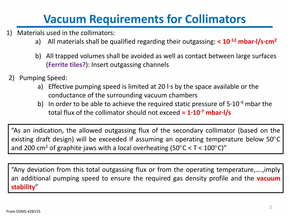
1) Materials used in the collimators: a) All materials shall be qualified regarding their outgassing: < 10-12 mbar∙l/s∙cm2
b) All trapped volumes shall be avoided as well as contact between large surfaces (Ferrite tiles?): Insert outgassing channels
From EDMS 428155
2) Pumping Speed: a) Effective pumping speed is limited at 20 l∙s by the space available or the
conductance of the surrounding vacuum chambers b) In order to be able to achieve the required static pressure of 5∙10-9 mbar the
total flux of the collimator should not exceed ≈ 1∙10-7 mbar∙l/s
“As an indication, the allowed outgassing flux of the secondary collimator (based on the existing draft design) will be exceeded if assuming an operating temperature below 50C and 200 cm2 of graphite jaws with a local overheating (50C < T < 100C)”
“Any deviation from this total outgassing flux or from the operating temperature,….,imply an additional pumping speed to ensure the required gas density profile and the vacuum stability”
Vacuum Stability: Ion Stimulated Desorption
3
S e1 I
ion
crit
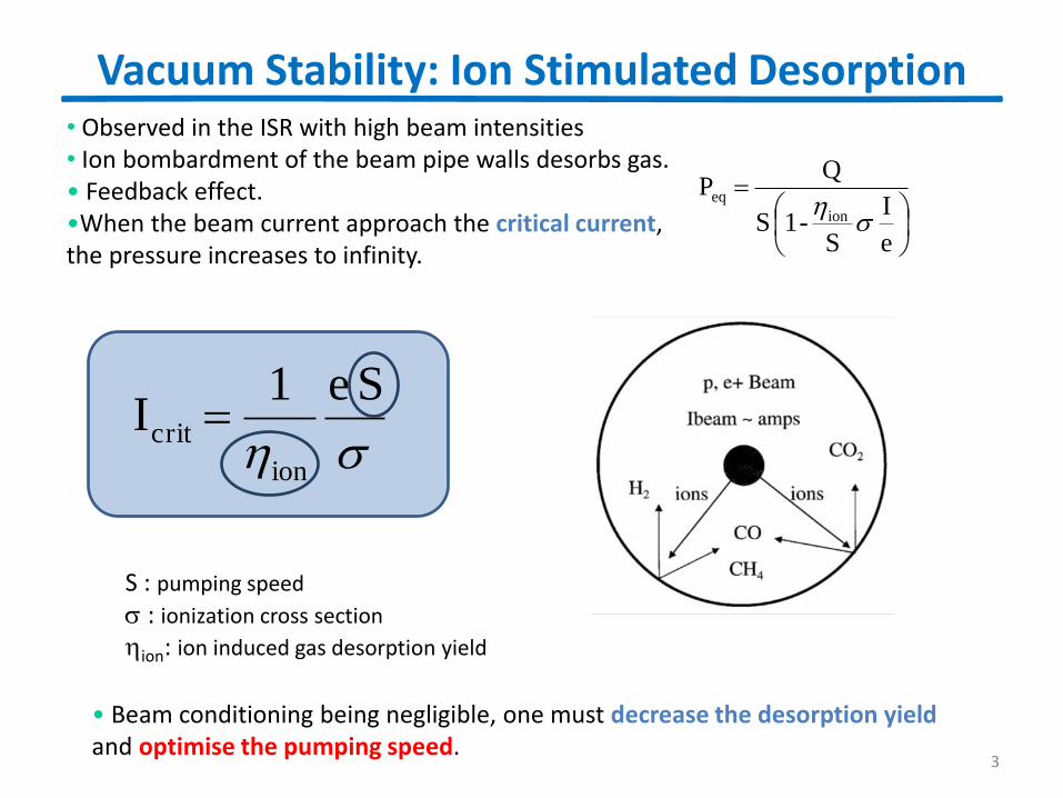
• Beam conditioning being negligible, one must decrease the desorption yield and optimise the pumping speed.
S : pumping speed
: ionization cross section
ion: ion induced gas desorption yield
• Observed in the ISR with high beam intensities • Ion bombardment of the beam pipe walls desorbs gas. • Feedback effect. •When the beam current approach the critical current, the pressure increases to infinity.
e
I
S-1 S
Q P
ion
eq
Room temperature beam vacuum system
4 From EDMS 339088
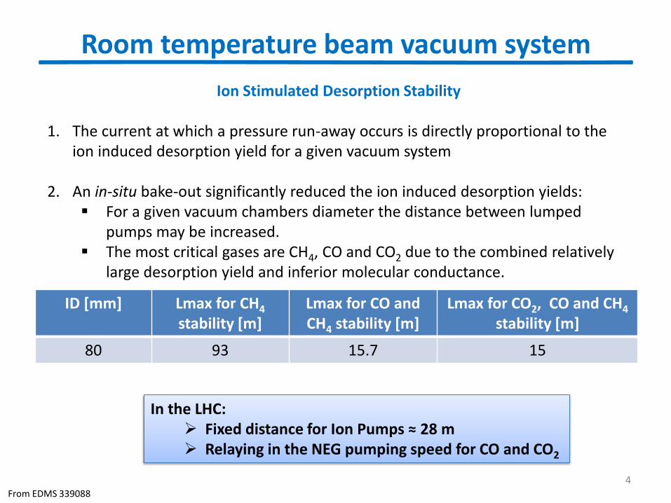
Ion Stimulated Desorption Stability 1. The current at which a pressure run-away occurs is directly proportional to the
ion induced desorption yield for a given vacuum system
2. An in-situ bake-out significantly reduced the ion induced desorption yields: For a given vacuum chambers diameter the distance between lumped
pumps may be increased. The most critical gases are CH4, CO and CO2 due to the combined relatively
large desorption yield and inferior molecular conductance.
ID [mm] Lmax for CH4 stability [m]
Lmax for CO and CH4 stability [m]
Lmax for CO2, CO and CH4 stability [m]
80 93 15.7 15
In the LHC: Fixed distance for Ion Pumps ≈ 28 m Relaying in the NEG pumping speed for CO and CO2
5
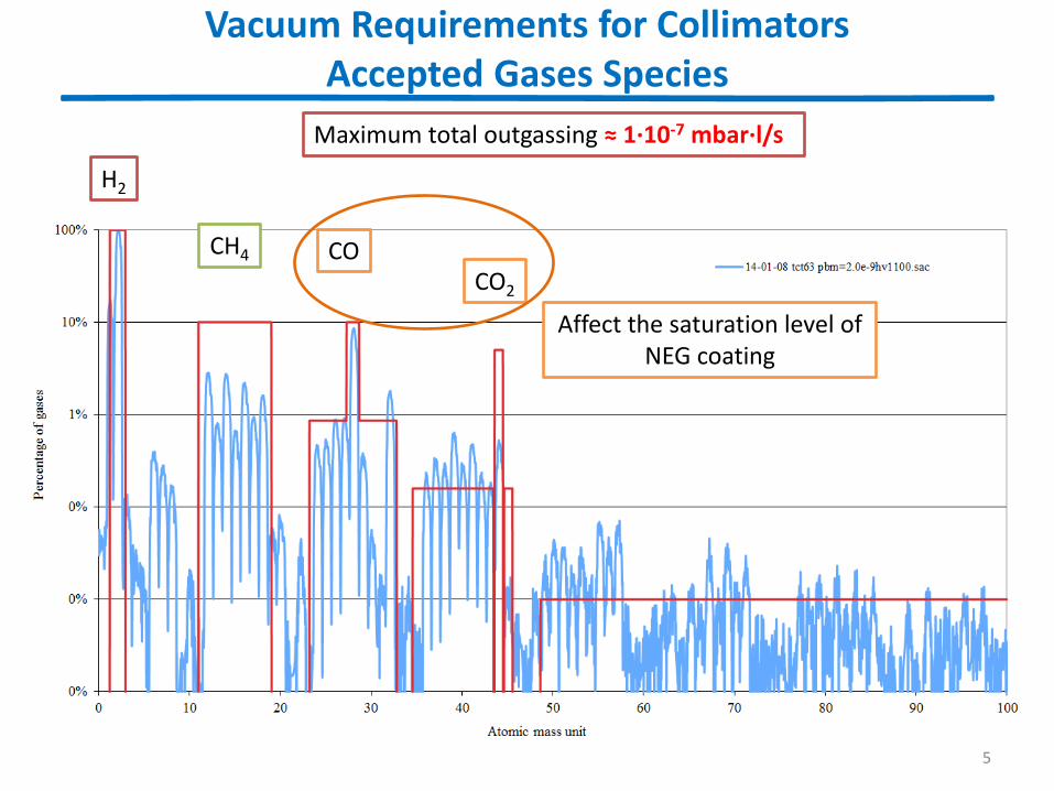
Vacuum Requirements for Collimators Accepted Gases Species
H2
CH4 CO
CO2
Maximum total outgassing ≈ 1∙10-7 mbar∙l/s
Affect the saturation level of NEG coating
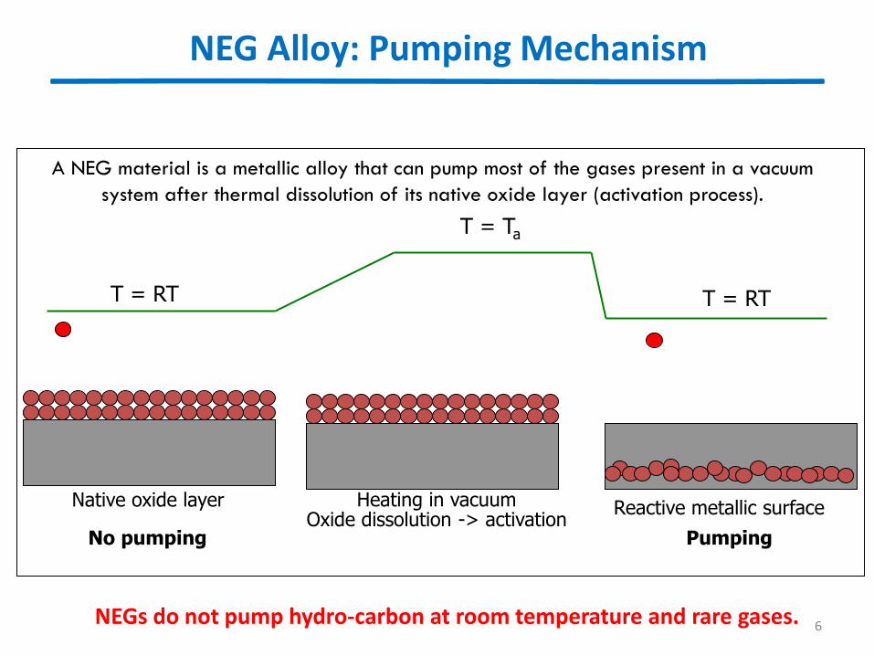
A NEG material is a metallic alloy that can pump most of the gases present in a vacuum
system after thermal dissolution of its native oxide layer (activation process).
Heating in vacuum Oxide dissolution -> activation
T = Ta
T = RT
Native oxide layer Reactive metallic surface
T = RT
No pumping Pumping
NEGs do not pump hydro-carbon at room temperature and rare gases.
NEG Alloy: Pumping Mechanism
6
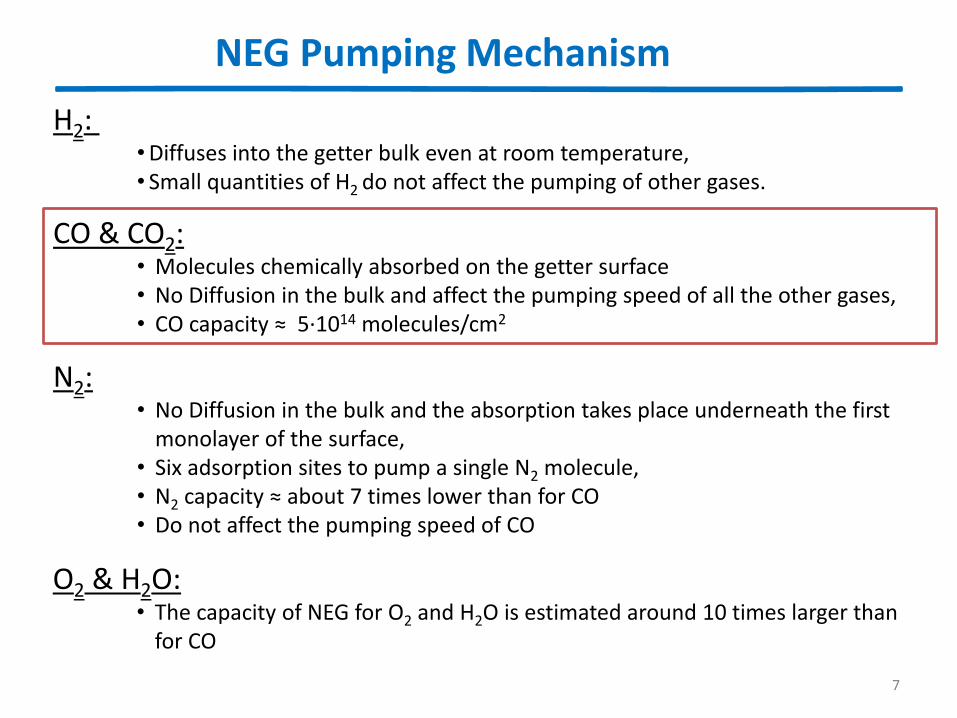
NEG Pumping Mechanism
7
H2: •Diffuses into the getter bulk even at room temperature, • Small quantities of H2 do not affect the pumping of other gases.
N2: • No Diffusion in the bulk and the absorption takes place underneath the first
monolayer of the surface, • Six adsorption sites to pump a single N2 molecule, • N2 capacity ≈ about 7 times lower than for CO • Do not affect the pumping speed of CO
CO & CO2: • Molecules chemically absorbed on the getter surface • No Diffusion in the bulk and affect the pumping speed of all the other gases, • CO capacity ≈ 5·1014 molecules/cm2
O2 & H2O: • The capacity of NEG for O2 and H2O is estimated around 10 times larger than
for CO
7

Small overview of the outgassing measurements for the collimators
8
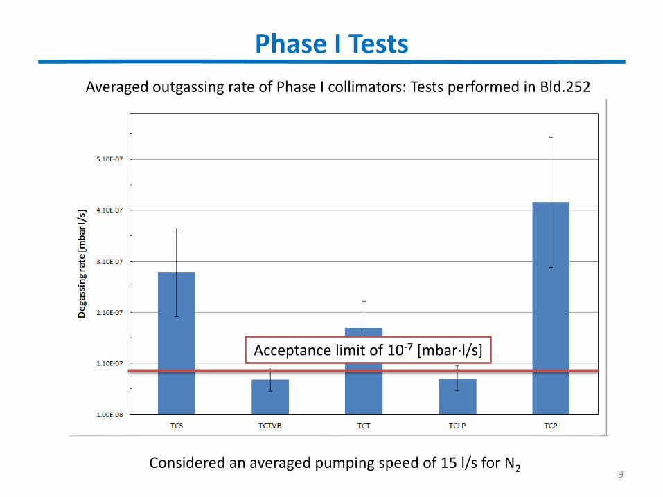
Phase I Tests
9
Averaged outgassing rate of Phase I collimators: Tests performed in Bld.252
Considered an averaged pumping speed of 15 l/s for N2
Acceptance limit of 10-7 [mbar∙l/s]
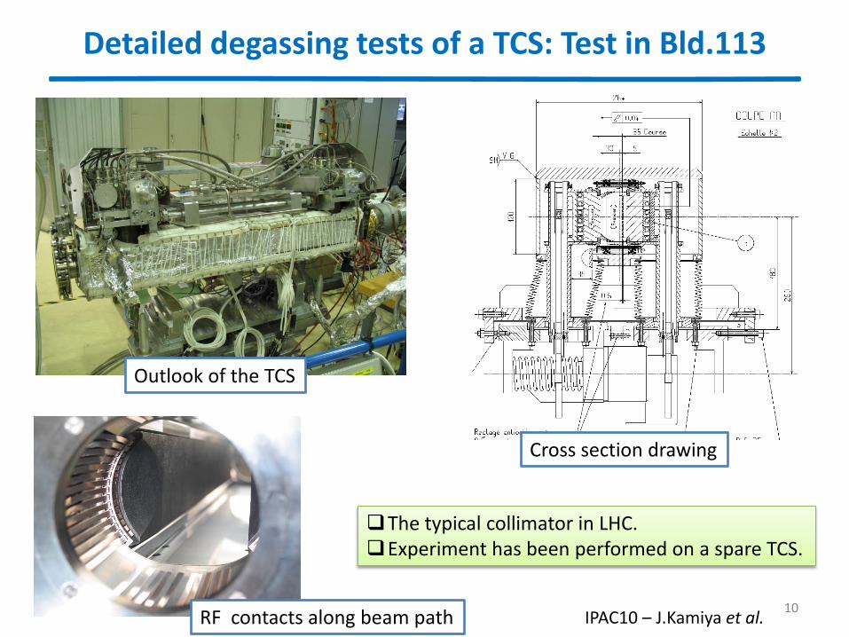
Detailed degassing tests of a TCS: Test in Bld.113
Outlook of the TCS
RF contacts along beam path
Cross section drawing
The typical collimator in LHC. Experiment has been performed on a spare TCS.
10 IPAC10 – J.Kamiya et al.
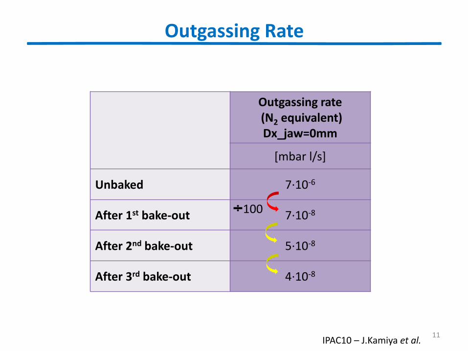
Outgassing Rate
Outgassing rate (N2 equivalent) Dx_jaw=0mm
[mbar l/s]
Unbaked 7∙10-6
After 1st bake-out 7∙10-8
After 2nd bake-out 5∙10-8
After 3rd bake-out 4∙10-8
100
11 IPAC10 – J.Kamiya et al.
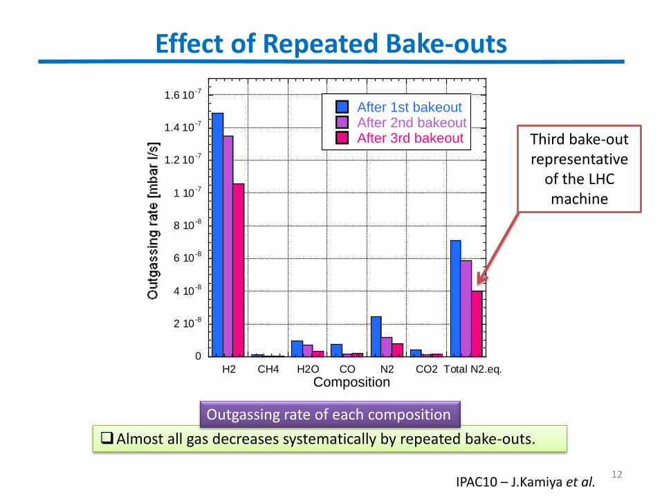
Effect of Repeated Bake-outs
0
2 10-8
4 10-8
6 10-8
8 10-8
1 10-7
1.2 10-7
1.4 10-7
1.6 10-7
H2 CH4 H2O CO N2 CO2 Total N2.eq.
After 1st bakeoutAfter 2nd bakeoutAfter 3rd bakeout
Composition
Almost all gas decreases systematically by repeated bake-outs.
Outgassing rate of each composition
12 IPAC10 – J.Kamiya et al.
Third bake-out representative
of the LHC machine
Acceptance limit for the new TCTP
13
TCTP Acceptance limits: Room temperature
14
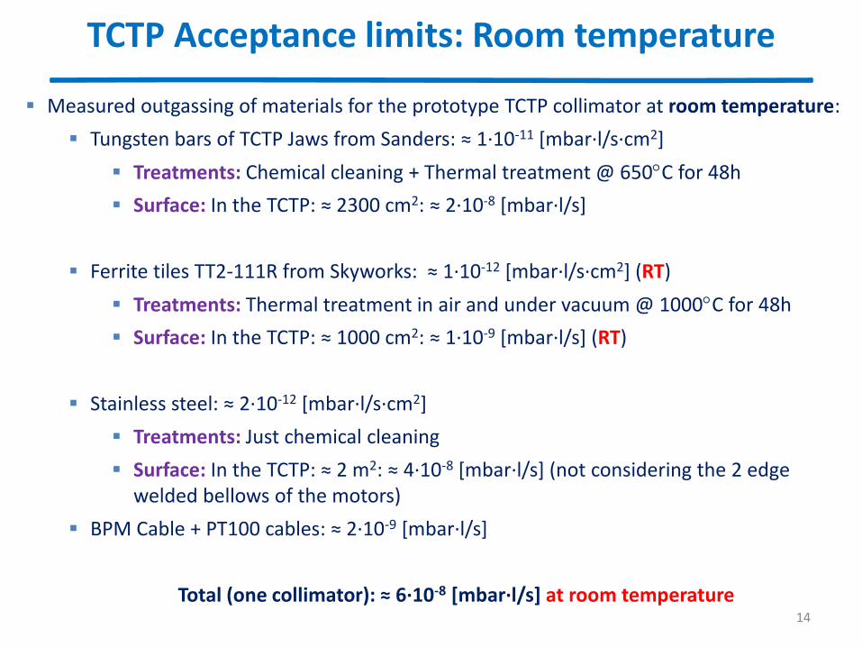
Measured outgassing of materials for the prototype TCTP collimator at room temperature:
Tungsten bars of TCTP Jaws from Sanders: ≈ 1∙10-11 [mbar∙l/s∙cm2]
Treatments: Chemical cleaning + Thermal treatment @ 650C for 48h
Surface: In the TCTP: ≈ 2300 cm2: ≈ 2∙10-8 [mbar∙l/s]
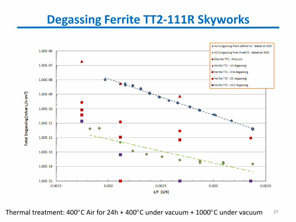
Ferrite tiles TT2-111R from Skyworks: ≈ 1∙10-12 [mbar∙l/s∙cm2] (RT)
Treatments: Thermal treatment in air and under vacuum @ 1000C for 48h
Surface: In the TCTP: ≈ 1000 cm2: ≈ 1∙10-9 [mbar∙l/s] (RT)
Stainless steel: ≈ 2∙10-12 [mbar∙l/s∙cm2]
Treatments: Just chemical cleaning
Surface: In the TCTP: ≈ 2 m2: ≈ 4∙10-8 [mbar∙l/s] (not considering the 2 edge welded bellows of the motors)
BPM Cable + PT100 cables: ≈ 2∙10-9 [mbar∙l/s]
Total (one collimator): ≈ 6∙10-8 [mbar∙l/s] at room temperature
Estimation of NEG life @ Room temperature
15
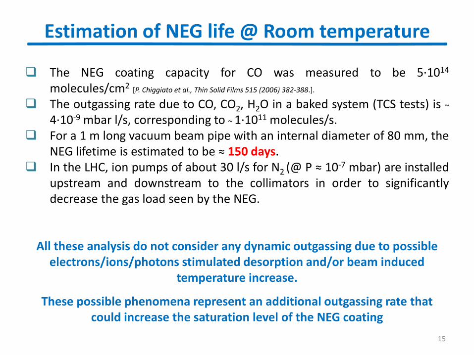
The NEG coating capacity for CO was measured to be 5∙1014 molecules/cm2 [P. Chiggiato et al., Thin Solid Films 515 (2006) 382-388.].
The outgassing rate due to CO, CO2, H2O in a baked system (TCS tests) is ~
4∙10-9 mbar l/s, corresponding to ~ 1∙1011 molecules/s. For a 1 m long vacuum beam pipe with an internal diameter of 80 mm, the
NEG lifetime is estimated to be ≈ 150 days. In the LHC, ion pumps of about 30 l/s for N2 (@ P ≈ 10-7 mbar) are installed
upstream and downstream to the collimators in order to significantly decrease the gas load seen by the NEG.
All these analysis do not consider any dynamic outgassing due to possible
electrons/ions/photons stimulated desorption and/or beam induced temperature increase.
These possible phenomena represent an additional outgassing rate that could increase the saturation level of the NEG coating

TCTP Acceptance limits: Ferrite @ ≈100C
16
Ferrite tiles TT2-111R from Skyworks: ≈ 4∙10-12 [mbar∙l/s∙cm2 ] (≈ 100C)
In the TCTP: ≈ 1000 cm2: ≈ 4∙10-9 [mbar∙l/s∙cm2 ] (≈ 100 C)
The ferrite at ≈ 100 C :
H2: ≈ 2∙10-12 [mbar∙l/s∙cm2 ] : Diffusion and not saturation of NEG coating
CO, CO2, H2O : ≈ 2∙10-12 [mbar∙l/s∙cm2 ] : No diffusion and saturation of NEG coating
Total (one collimator): ≈ 7∙10-8 [mbar∙l/s] with ferrite at ≈ 100 C
Estimation for NEG life with Ferrite @ ≈ 100C
The outgassing rate with ferrite @ 100C is ~ 2∙10-9 [mbar l/s] corresponding to ~ 5∙10+10 molecules/s.
Total outgassing for saturation: 2∙10-9 + 4∙10-9 [mbar l/s]
NEG lifetime is estimated to be 100 days
All these analysis do not consider any dynamic outgassing (as stated in previous slide).
Outlook and Conclusion
17
Outlook: LS1 Activities in the LSS
18
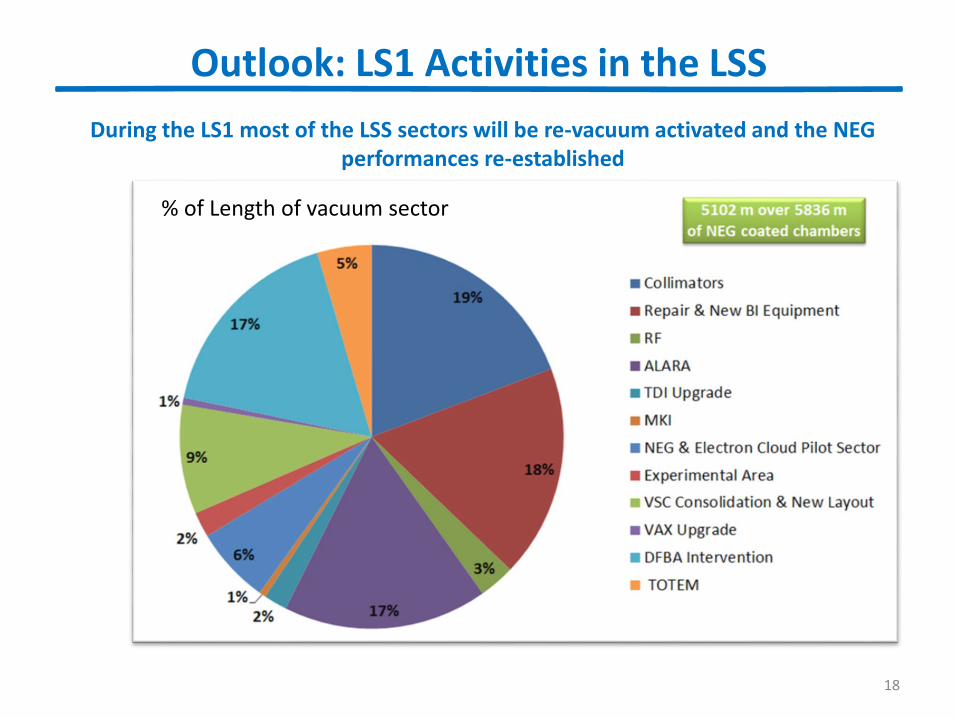
During the LS1 most of the LSS sectors will be re-vacuum activated and the NEG performances re-established
Number of vacuum sector % of Length of vacuum sector
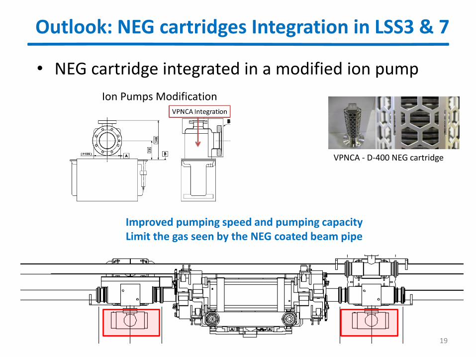
Outlook: NEG cartridges Integration in LSS3 & 7
19
• NEG cartridge integrated in a modified ion pump
Ion Pumps Modification
VPNCA - D-400 NEG cartridge
Improved pumping speed and pumping capacity Limit the gas seen by the NEG coated beam pipe
Conclusion: Outgassing rate of the TCTP
20
The degassing rate of the TCTP is approaching the vacuum accepted limits: What could be improved?
Thermal treatments (vacuum firing) of all the components especially all the stainless steels parts?
Ferrite tiles outgassing at RT are within the vacuum acceptance limit: However:
Ferrites could be a sort of “antenna” for HOM effects: Are we sure about the right location and the maximum possible reached temperature? What can we do in case of increase up to 200C or even more ?
Would been necessary to think of a cooling system for the ferrite?
Would been interesting (or better necessary) to have a reliable temperature measurements of the ferrite tiles seen the BSRT experience in 2012?
Conclusion: Increase the temperature interlock for collimators
21
NEG saturation could produce an increase background: Reversible just after NEG vacuum activation
4 days minimum of activities Re-conditioning + scrubbing of the not coated area: much
faster, but must be taken in consideration
In some area ALARA principle: not possible in a short delay of time to repeat a NEG vacuum activation if something will happen
The sector valve interlock could and must be increased
Production of more radiation: Impact to the R2E?
If saturation of the NEG pumping capacity will decrease: Possible limitation to the 100h of beam lifetime Possible vacuum stability issues
Increase the temperature for a limited time is not a problem What should be considered is the integrated time of the produced outgassing

Thanks you for your attention
Spare slides
23
Overview of pressure evolution in the LSS with beam Effects of the dynamic vacuum on the saturation of
the NEG coating
24
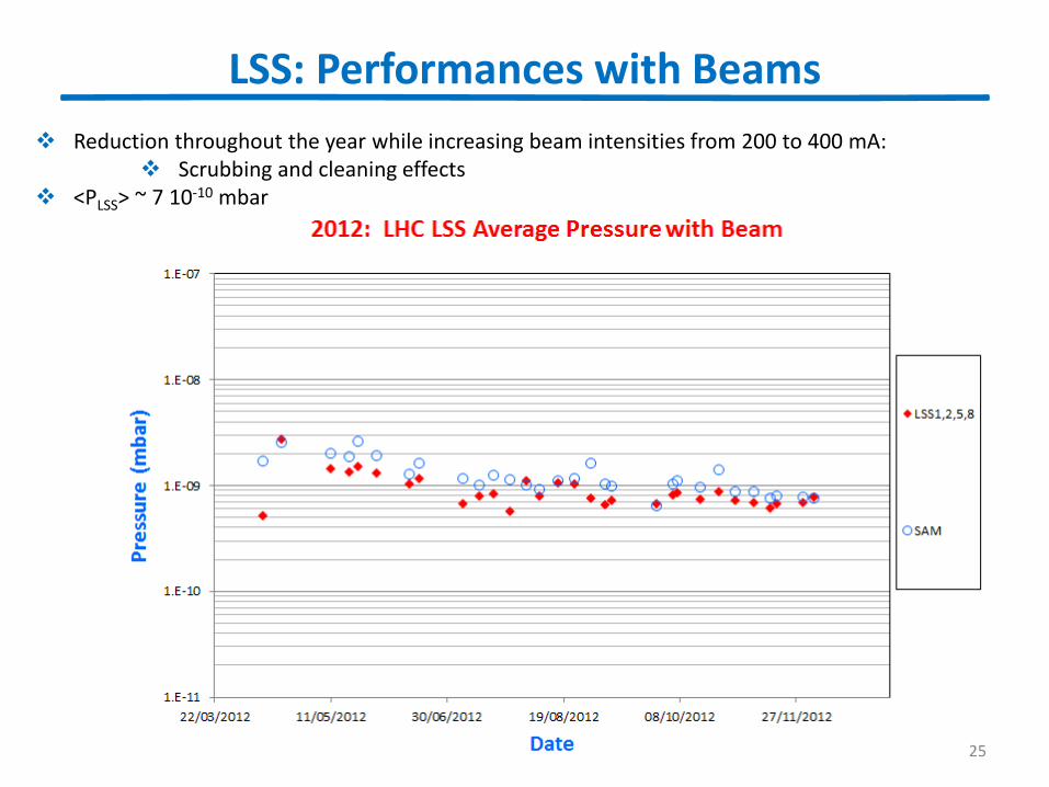
LSS: Performances with Beams
25
Reduction throughout the year while increasing beam intensities from 200 to 400 mA: Scrubbing and cleaning effects
<PLSS> ~ 7 10-10 mbar
No
rmal
ize
d P
ress
ure
[m
bar
/mA
]
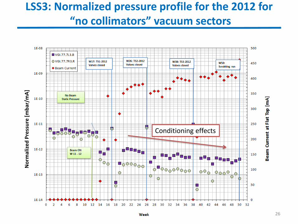
LSS3: Normalized pressure profile for the 2012 for “no collimators” vacuum sectors
26
Conditioning effects
No
rmal
ize
d P
ress
ure
[m
bar
/mA
]
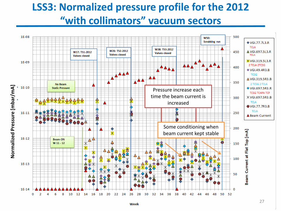
Pressure increase each time the beam current is
increased
Some conditioning when beam current kept stable
LSS3: Normalized pressure profile for the 2012 “with collimators” vacuum sectors
27
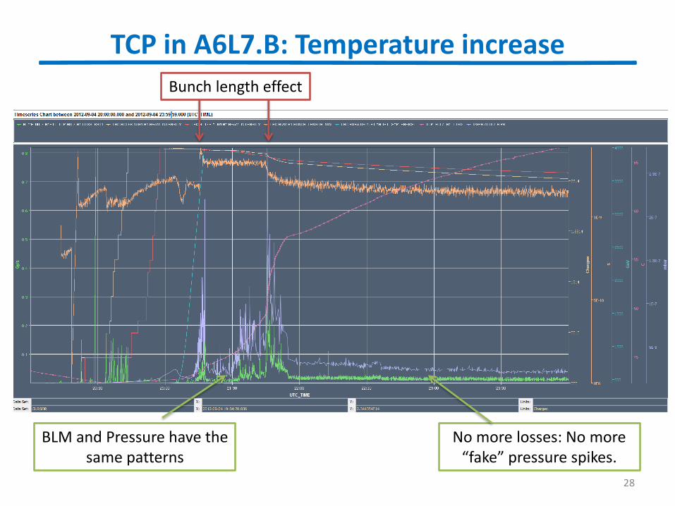
Bunch length effect
BLM and Pressure have the same patterns
TCP in A6L7.B: Temperature increase
28
No more losses: No more “fake” pressure spikes.
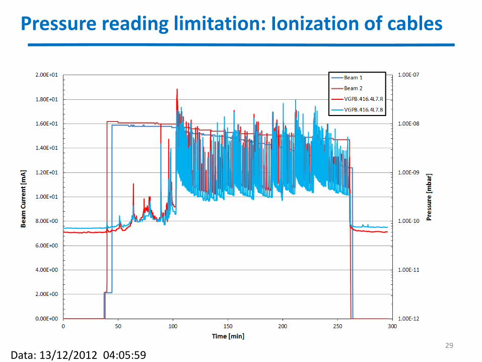
Pressure reading limitation: Ionization of cables
29
Data: 13/12/2012 04:05:59
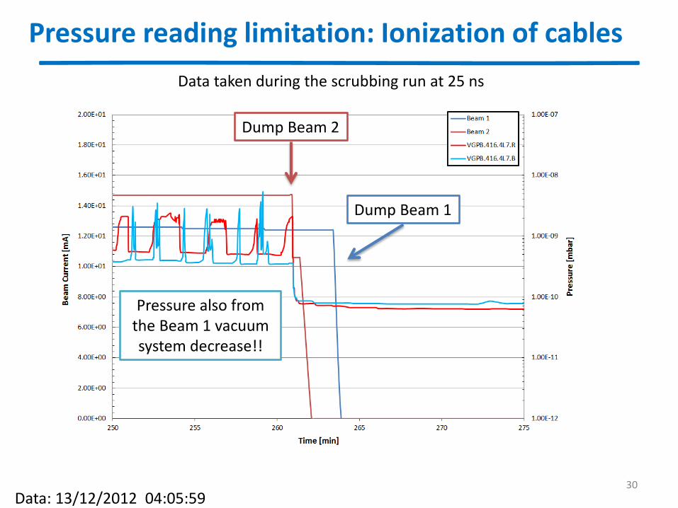
Pressure reading limitation: Ionization of cables
30
Dump Beam 2
Pressure also from the Beam 1 vacuum system decrease!!
Dump Beam 1
Data: 13/12/2012 04:05:59
Data taken during the scrubbing run at 25 ns
Effects of the dynamic vacuum outgassing on the NEG saturation level
31
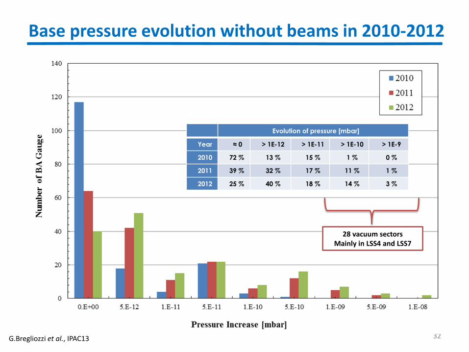
Base pressure evolution without beams in 2010-2012
32 G.Bregliozzi et al., IPAC13
Evolution of pressure [mbar]
Year ≈ 0 > 1E-12 > 1E-11 > 1E-10 > 1E-9
2010 72 % 13 % 15 % 1 % 0 %
2011 39 % 32 % 17 % 11 % 1 %
2012 25 % 40 % 18 % 14 % 3 %
28 vacuum sectors Mainly in LSS4 and LSS7
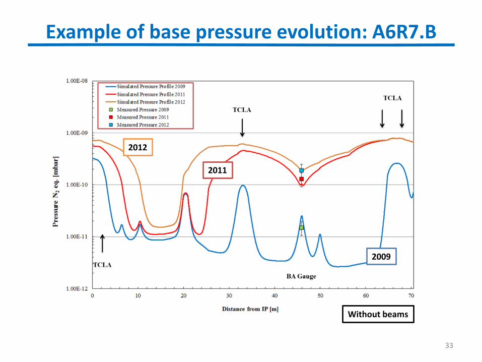
Example of base pressure evolution: A6R7.B
33
Without beams
2009
2011
2012
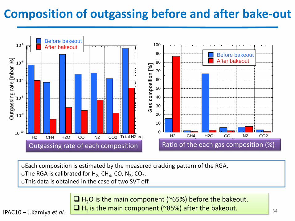
Composition of outgassing before and after bake-out
oEach composition is estimated by the measured cracking pattern of the RGA. oThe RGA is calibrated for H2, CH4, CO, N2, CO2. oThis data is obtained in the case of two SVT off.
H2O is the main component (~65%) before the bakeout. H2 is the main component (~85%) after the bakeout.
10-10
10-9
10-8
10-7
10-6
10-5
H2 CH4 H2O CO N2 CO2 Total N2.eq.
Before bakeoutAfter bakeout
Outgas composition
0
10
20
30
40
50
60
70
80
90
100
H2 CH4 H2O CO N2 CO2
Before bakeoutAfter bakeout
Outgas compositionOutgassing rate of each composition Ratio of the each gas composition (%)
34 IPAC10 – J.Kamiya et al.
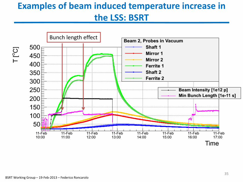
Examples of beam induced temperature increase in the LSS: BSRT
35 BSRT Working Group – 19-Feb-2013 – Federico Roncarolo
Bunch length effect
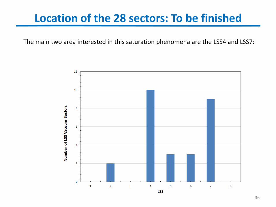
Location of the 28 sectors: To be finished
36
The main two area interested in this saturation phenomena are the LSS4 and LSS7:
37
Degassing Ferrite TT2-111R Skyworks
Thermal treatment: 400C Air for 24h + 400C under vacuum + 1000C under vacuum