coupling joints of prestressing tendons 1n continuous post
TRANSCRIPT

Transportation Research Record 1044 43
Coupling Joints of Prestressing Tendons 1n
Continuous Post-Tensioned Concrete Bridges
FRIEDER SEIBLE
ABSTRACT
Large cracks and ruptured tendons encountered in the coupling joint vicinity of post-tensioned, continuous concrete bridge structures in the Federal Republic of Germany have, in recent years, led to an intensified bridge inspection program and extensive investigations. The results of the inspection program and the investigations into the probable causes for the encountered cracks are summarized and discussed in this paper to provide a basic understanding of the complex behavior of these coupling joints. Low fatigue stress limits for tendon coupler assemblies and stress crack corrosion are shown to be the main reasons why cracks in the coupling joint vicinity are so detrimental to the structural integrity. To avoid these cracks in the seemingly insensitive vicinity of the point of inflection for sustained loads, special design considerations have to be made in determining possible moment variations at that point. The highly nonlinear behavior in the construction and coupling joint vicinity due to tendon anchorages, coupler forces, and temperature differences has to be understood and accounted for. Special detailing has to be provided for the increase in loss of pres tress force in the coupler, which is shown to cause substantial concentrated forces. With the understanding of the complex coupling joint behavior, possible rehabilitation measures for damaged bridge structures are presented and important design considerations for new bridge structures are summarized.
The serviceability and safety of existing concrete structures can often only be judged by visual inspection of the concrete surface for cracks. Although virtually every concrete structure features fine surface cracks or hairline cracks that originate early in the life of the structure as a result of differences in heat of hydration and shrinkage, it is the larger cracks with crack widths of approximately .01 in. or more that generally point to some structural deficiency or potential problem. The formation of cracks and their penetration to the prestressing reinforcement is of particular importance in prestressed concrete structures because of the increased susceptibility of high-strength steel to stress crack corrosion and the significant reduction in structural capacity with the loss of one or more of the prestressing tendons.
Prestressed concrete members have been extensively and economically used in bridge construction during the last 30 years, simply supported for short- and medium-span bridges and continuous for large-span bridges. Routine inspections of these bridge structures have revealed a variety of problems ranging from bearings to transition joints and from support settlements to cracks in the superstructure. A repetitive occurrence of deficiencies in similar types of structures generally points to a common. design problem. The purpose of this paper is to describe, summarize, and evaluate one of these problems--cracks in the vicinity of coupling joints of prestressing tendons in post-tensioned, continuous concrete bridges.
EXPERIENCE WITH COUPLING JOINTS IN EXISTING BRIDGE STRUCTURES
Routine bridge inspections in the Federal Republic of Germany almost 20 years ago showed an increased
occurrence of cracks in the vicinity of coupling joints of pres tressing tendons in continuous, posttensioned concrete bridges (1). However, it was not until 1976 when a bridge st"iucture near Dilsseldor f showed an increase in the width of these cracks of up to .1 in. (approximately .2 mm) that subsequent radiographic scans revealed ruptured tendons in the bottom soffit at the construction joint where the post-tensioned threadbars had been coupled during the span-by-span construction of the superstructure
<1J. These findings started an intensified inspection
of all the prestressed concrete bridges in the Federal Republic of Germany and other European countries. In December 1980, the Ministry of Transportation released results of that investigation (~). At this time, a total of 2,431 prestressed concrete bridge structures with 11,458 spans had been inspected. Classification criteria for the inspection were: (a) no cracks, (b) cracks that are smaller than .01 in. (< .2 mm) in width, and (c) crack widths at or beyond that limit. The seemingly arbitrary .01 in. (approximately .2 mm) crack width criterion (3) is based on the fact that smaller cracks remain generally unnoticed with simple visual inspection and that cracks below that criterion have generally only limited penetration and thus can be considered harmless. Cracks at or above this width criterion are not proven to be detrimental to the structural integrity; however, with increased use of deicing salts on bridge structures and increasing levels of acid pollutants in the environment, cracks at or above that limit can have enough penetration to cause potential problems for the reinforcement.
The results of the investigation (~) are given in Table 1, where the total bridge population is subdivided into bridges with and without coupling joints. Table 1 gives bridge structures with and

44
TABLE 1 Results of Bridge Inspection, Status 12-31-80 Ministry of Transportation, Federal Republic of Germany (2)
~u::=.~! Uli!!! Prestressed Concrete Coupling Coupling Bridge Structures Joints Joints Total
No cracks 1,477 (88%) 196 (12%) 1,673 (100%) (80%) (34%) (69%)
Cracks< 0.2 mm 187 (54%) 160 (46%) 347 (100%) (10%) (27%) (14%)
Cracks;;. 0.2 mm 184 (45%) 227 (55%) 411(100%) (10%) (39%) (17%)
Total 1,848 583 2,431 (100%) (100%) (I 00%)
without cracks not only by number, but also in parentheses, the individual percentage distributions with respect to corresponding top or left-column .r.,ference values. It can be seen that the bridges with coupling joints show not only a tendency toward having more cracks than bridges without coupling joints, but also a tendency toward wider cracks. While the statistics in Table 1 are for all cracks encountered in a bridge structure, it also is interesting to note that 104 br idges--almost one-half of the 227 bridges (cracks > • 2 mm) with coupling joi nts--showed these cracks in the direct vicinity of the coupling joints. It shou l d be noted thar. r.he survey (2) includes only bridge structures with coupling -joints built before 1977, at which time substantial changes in the code provisions for cou-
COMPLETED SECTION NEXT SECTION
~~~~--------~---------~ I ~ --------- - - ----1
--..._,1,.----r-- TEN DON COUPLERS I
I
TENDONS
- 0 2L
FIGURE 1 Coupling joint.
Transportation Research Record 1044
pling joint design were introduced into the West German Standards for prestressed concrete.
CRACK DEVELOPMENT I N COUPLING JOINT VICINITY
The coupling of prestressing tendons as shown schematically in Figure 1 is primarily used for mediumspan, continuous, post-tensioned bridge structures with a large number of repetitive spans. Two construction methods that proved to be economical in these cases were the span-by-span construction with traveling self-supporting falsework ana the incremental launching method (see Figure 2). Bridge cross-sections most frequently used for these methods are shown in Figure 3. While expensive scaffolding is no longer needed, both methods rely on the early post-tensioning of each new section to the alreadybuilt bridge structure. This is accomplished by coupling the prestressing tendons in the construction joints (:;.,., Figur" 4). In the span-by-span construction method, the construction and coupling joints are generally located at the theoretical point of inflection for sustained loads (combined dead load and prestressing) and it is at these locations that severe cracking parallel to the construction joints was encountered in the bottom soffi t and lower web portions of the bridge structure.
Substantial investigations of these phenomena (l_-2l have led to the following possible causes pointing to inadequate design for:
• variations of sustained loads, ' Secondary moments and nonlinear stress dis
tributions resulting from temperature differences, Time-dependent moment redistributions,
• Support settlements, • Nonlinear (local) stress state in coupling
joint, • Increased loss of prestress in coupling joint, • Inaccuracies in prestressing force due to
friction, and • Heat of hydration and creep and shrinkage
differences in adjacent members with different dimensions.
Although most of the preceding points are common problems in bridge design, their implication in the particular case of a coupling joint at the point of inflection of a bridge structure is of importance.
Coupling Joint
SPAN BY SPAN ERECTION WITH TRAVELLING SELFSUPPORTING FALSEWORK
INCREMENTAL LAUNCHING METHOD
(onctntrlc Prestressing
FIGURE 2 Construction methods with coupling joints.
Launching Nose
--

Seible 45
BOX GIRDER T - BEAH
\\ 7/LJ \oor ~
r FIGURE 3 Typical cross sections for sectional construction methods.
TREADBAR ( OUPLER
Coupler
I" 220
j~b FIXED TENDON
l~b 700
Coupler
l.J= J';
ZQQ
COUPLER
M2~
2J)
700
~~
Section b-b 1
{i
MOVABLE TENDON COUPLER
FIGURE 4 Prestressing couplers (dimensions in millimeters).
Variations in Point of Inflection and Design Moments
Construction joints are placed at the point of inflection for sustained loads to minimize the amount of reinforcement required at that section. Generally, only minimum reinforcement or a minimum amount of pres tress will be provided in the design. However, the location of the point of inflection can change because of variations in the sustained loads (e.g., variations in dead load and pres tressing forces), thus introducing moments at the design point of inflection (~). If these moments are superimposed with possible variations in the determination of secondary temperature effects, support settlements, and overestimated moment redistributions in the structure due to the span-by-span erection process and creep and shrinkage, the design moment at this location can change significantly, not only in magnitude but also in sign. Small moment changes in areas of large design moments are generally sufficiently provided
for by the applied load and safety factors, whereas areas of small design moments do not have this built-in safety feature and have to be much more carefully evaluated for these moment variations (see Figure 5). Although this is the case in all con·t inuous bridge structures in the vicinity of the point of inflection for sustained loads, problems may arise if this area is weakened by a construction joint and, in addition, by tendon anchorages and couplers.
Nonlinear Stress Distribution
The temperature distribution over the depth of a bridge structure is generally parabolic with extreme values at the top and bottom fibers (6). Most analyses account for the linear portion of the resulting stress distribution by assuming a certain temperature difference, [IT, over the structural depth and

46
, I
/ I r
/1\ I ' I -'~-- - AH
Q..,.---";-_- •6M
0
\~ Factored Design Moment
(alculatod Moment \
\ \
- 0.2L
\
' ' :,..
llM = Homen I Olanges
FIGURE 5 Safety against L'IM.
neglect the nonlinear self-equilibrating stress state.
Anchorage zones of prestressing tendons are known to require special design considerations to allow the proper transition from locally, highly concentrated forces to distributed stress states over the structure. In most cases, these anchorage zones coincide with the member ends where simple supports ana zero moment conditions provide an insensiti;te environment to the nonlinear anchor stresses.
In cases where tendons are anchored, over lapped, or terminated within the structure, flexure and anchor forces act simultaneously. However, in the majority of these cases, only one or two of the tendons are anchored in one section, while the remaining tendons provide not only continuity, but also a fairly uniform state of stress over the entire member. Sufficient back anchorage reinforcement as well as the splitting reinforcement common to all anchor zones treats the anchor problem locally, while still, linear stress distributions and the plan& ~ection hypothesis are applied for the overall member.
The problem of nonlinear stress distributions is intensified in a construction joint which, in itself, disrupts the homogeneity of the structure. If, in one construction joint, a large number and, in some cases, all, of the post-tensioning tendons are temporarily anchored and then subsequently coupled and reloaded, the stress state in the coupling joint vicinity will be far from linear and plane sections will not remain plane. Thus, overall stress states in the structure have to be designed with significant allowances for the highly nonlinear behavior in these sections. Only substantial reserves in the available compressive stresses avoid local tensile zones where potentially dangerous cracks can form.
Loss of Prestressing Force in Coupler
Another phenomenon complicating the local stress states in coupling joints is the difference in loss of pres tress in the tendon and the coupler itself. The simple assumption of a uniform time-dependent shortening of the entire member would result in a uniform strain increment 6<c+s due to creep and shrinkage over the entire member length. With Young's Modulus Es assumed to be the same for both prestressing tendons and coupler, the simple theory of elasticity shows direct proportionality between the loss of pres tress force, P, and the cross-sectional area of the tendon. However, this area can be substantially larger in the coupler than in the strand or bar as a result of the use of lower strength material, which suggests significant prestress losses in the coupler.
Transportation Research Record 1044
A commonly accepted formula for the prestress loss due to creep and shrinkage in a single tendon adopted in the CEB-FIP Model Code for Concrete Structures (8) and originally developed by Ruesch (~) takes the interaction between the prestress force and the amount of creep into account
fps,C+S
where
+ [l - n (£<6,plfgs> 1 + (~/2))
fps,C+S = prestress loss due to creep and shrinkage,
(1)
£ s = shrinkage coefficients (0. 00032) , ~ = creep coefficient (2.0), n = Es/Ee with Es = 29 x 10 3 ksi
(7 .0) , fc,DL s concrete stress at tendon level due
to Dl,(0) 1
fc,p = concrete stress at tendon level due to P, tensile stress in tendon = P/Aps• and
superscript o time at transfer.
With creep and shrinkage coefficients according to Reference 8 for general outside conditions and fc,DL ~s~umea to be negligibla ~t the point cf inflection, Equation 1 can be transformed to the loss of prestress in the tendon as
6P[%) [(-9.28 + 14.0 f2,p>
(pO - 14.0 f8,p Apsll Aps (2)
with P0 representing the initial prestress force in the tendon at transfer. For tendons made up of individual strands vidual strands with P0 being directly proportional to Aps• Equation 2 proves to be independent of the tendon size (number of strands).
A plot of Equation 2 for a low level of f2,p = -500 psi and a high level of fg = -2000 psi shows the range of pres tress loss depen~nt on the normalized prestressed steel area in Figure 6. The normalization is with respect to the tendon area (crosssection of prestressing strands or bars) with the coupler area expressed as a multiple of the tendon area.
For an arbitrary prestressing tendon and an average value of compressive stress fg P' Figure 6 shows a 13 percent loss of prestress force in the tendon while in a coupler that is 5 times the crosc-cec-tional area of the tendon the loss of prestress force would amount to 46 p~rcent= For a tendon: ~omprised
of 12 x 0.6 in. diameter strands, with P0 = 0.7 fpu x ~s = 492.2 kips, the prestress losses amount to 64 kips and 226 kips in the tendon and coupler, respectively. The difference in loss of prestress force of 166 kips can only be accounted for if compressive forces as shown in Figure 7 act on the coupler faces (bond between coupler and concrete is neglected) and, in return, on the concrete section as bearing pressure from the coupler faces. These forces have the tendency to jack the construction joint apart and, therefore, need special design attention. If only these prying forces from the coupler would be present, the construction joint would open up, with compression trajectories as shown in Figure 7 and the only required reinforcement would be the splitting reinforcement, Ts· However, with a certain state of compression available due to prestress, tensile forces Tc can be transferred in the construction joint and the amount of additional tension

Seible
LI Pl%1 Loss in Pres1ress Force
BO
70
60 f~.P= 2000 psi
50
30
20
10
10 Aps
Aps,tendon
for 12 - O 6" tendon with P' = 0.7 fpuAps = 492 .2 kips
/::. Ptendon = 13% of P' = 6~ kips
/::. Pcoup ler = 46% of p" • 226 kips
FIGURE 6 Prestress loss in tendon and coupler.
TENDON FORCES
~/::.~rt-----=j=t I f .. ,,_,,,~_-;;,-P0 - t:.P,
CONCRETE FORCES
I v : Ts I
I I
I A I
FIGURE 7 Forces in coupling joint vicinity.
reinforcement to prevent the construction joint from opening depends on the level of prestress.
Although it should be kept in mind that the pres tress loss in the coupler was derived using Equation 1, which is based on the Bernoulli hypothesis that plane sections remain plane, more elaborate finite element analyses (~) have shown that even though the true prestress loss in the coupler is somewhat lower than predicted by Equation 1, the general tendency of significant local forces, due to cross-sectional differences between coupler and tendon, remains. It should also be noted that different post-tensioning systems use different coupler geometries with different coupler areas and therefore exhibit different amounts of prestress loss in the couplers according to Figure 6.
CONSEQUENCES OF CRACKS IN COUPLING JOINT VICINITY
Large cracks in any prestressed concrete structure can lead to stress crack corrosion of the tendons especially in environments where deicing salts or
47
acid pollutants frequently occur. The problem intensifies significantly when, in addition, cyclic loading with large stress ranges and stress concentrations at the transition from the tendon to the coupler are present.
In fully pres tressed bridge structures, the fatigue behavior of the tendons is generally insignificant due to the low cyclic stress ranges under traffic loads in the uncracked section and the high fatigue stress ranges commonly encountered in prestressing steel (10). Thus, no special design criteria for fatigue -Of prestressing tendons have been established in the current AASHTO Standard Specifications (11).
With c~cks developing in the bottom soffit of a bridge structure in the coupling joint vicinity, the cyclic stress range experienced by the bottom tendons increases significantly as shown in Figure 8, due to the change in flexural stiffness. Finally, the fatigue stress range for the standard 2 x 10 6 load cycles is substantially lower for the coupler and anchor plate connections than for the high strength tendon (10). FIP recommendations for allowable fatigue stress ranges are for the tendons 0.10 x (prestress at ultimate) = 27 ksi (for 270 ksi strands) and 11 ksi for the tendon-anchorage assembly (10) , which can also be applied to the coupling zones. The 11 ksi allowable fatigue stress range in the coupling joint can often be exceeded in a cracked section under regular traffic conditions that could then lead to a premature stress crack corrosion fatigue failure at the tendon coupler.
MOMENT M
~~-NA-Prototype - - _i~ - - - -NA-Design
' , I
1: ,, :: :: " ..
Deg ree of Prestress
. ...;..- . - · -t crocked
! uncrocked
BOTTOM TENDON STRESS fps
FIGURE 8 Sketch of tendon stresses.
REHABILITATION OF CRACKED COUPLING JOINTS
Awareness of these findings allows the structural engineer to adequately design coupling joints in new bridge structures. Existing cracked bridge structures that were designed without sufficient reserves of compressive stresses and inadequate numbers or no rebars at all in the coupling joint have to be rehabilitated to ensure strength and serviceability.
Two prime objectives have to be achieved: (a) the closing of existing cracks to prevent hazardous environments from reaching the tendons and (b) the addition of flexural stiffness in these sections to minimize the cyclic stress levels. Although the first objective is generally achieved by injection of the cracks with epoxy compounds, large cracks can be avoided by adding composite steel or structural concrete splices (~) to the bottom slab and lower web
--
48
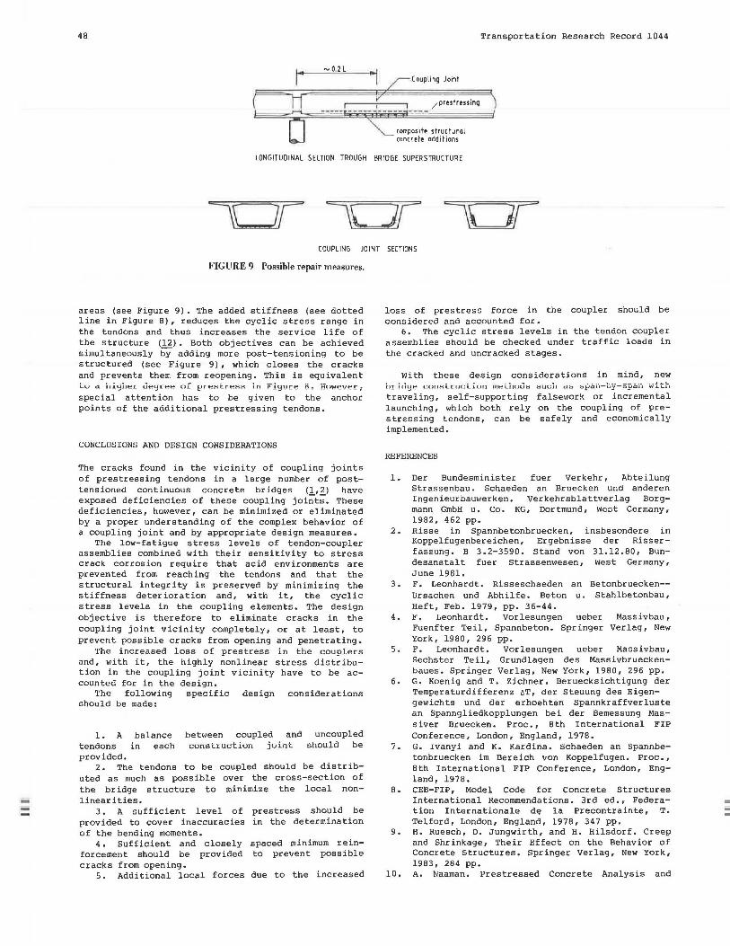
-0.2 L Coupling Joint
/pres tressing
composito structural concreto additions
Transportation Research Record 1044
LONGITUDINAL SECTION TROUGH BRIDGE SUPERSTRUCTURE
COUPLING JOINT SECTIONS
FIGURE 9 Possible repair measures.
areas (see Figure 9). The added stiffness (see dotted line in Figure 8), reduces the cyclic stress range in the tendons and thus increases the service life of the structure (12) • Both objectives can be achieved simultaneously by adding more post-tensioning to be structured (see Figure 9) , which closes the cracks and prevents them from reopening. This is equivalent to a highe r deg r ee o f pre8treBs in Figure 8~ However, special attention has to be given to the anchor points of the additional prestressing tendons.
CONCLUSIONS AND DESIGN CONSIDERATIONS
The cracks found in the vicinity of coupling joints of prestressing tendons in a large number of posttensioned continuous concrete bridges (1,2) have exposed deficiencies of these coupling joii;'°t;. These deficiencies, however, can be minimized or eliminated by a proper understanding of the complex behavior of a coupling joint and by appropriate design measures.
The low-fatigue stress levels of tendon-coupler assemblies combined with their sensitivity to stress crack corrosion require that acid environments are prevented from reaching the tendons and that the structural integrity is preserved by minimizing the stiffness deterioration and, with it, the cyclic stress levels in the coupling elements. The design objective is therefore to eliminate cracks in the coupling joint vicinity completely, or at least, to prevent possible cracks from opening and penetrating.
The increased loss of prestress in the coupl<>rs and, with it, the highly nonlinear stress distribution in the coupling joint vicinity have to be accounted for in the design.
The following specific design considerations should be made:
1. A
tendons balance
in each between coupled and construct i on joint
uncoupled should be
provided. 2. The tendons to be coupled should be distrib
uted as much as possible over the cross-section of the bridge structure to minimize the local nonlinearities.
3. A sufficient level of prestress should be provided to cover inaccuracies of the bending moments.
4. Sufficient and closely forcement should be provided cracks from opening.
in the determination
spaced minimum reinto prevent possible
5. Additional local forces due to the increased
loss of prestress force in the coupler should be considered and accounted for.
6. The cyclic stress levels in the tendon coupler assemblies should be checked under traffic loads in the cracked and uncracked stages.
With these design considerations in mind, new br id~e cons tr uct. i on 1oetb0Us traveling, self-supporting launching, which both rely stressing tendons, can be implemented.
REFERENCES
- - _,_ - - ....,--- L.-- ---- __ .: .&..k bU{.;11 db b.Pd.U-uy-~l-'d.11 W.LL.U
falsework or incremental on the coupling of presaf ely and economically
1. Der Bundesminister fuer Verkehr, Abteilung Strassenbau. Schaeden an Bruecken und anderen Ingenieurbauwerken. verkehrsblattverlag Borgmann GmbH u. Co. KG, Dortmund, Wcot Germany, 1982, 462 pp.
2. Risse in Spannbetonbruecken, insbesondere in Koppelfugenbereichen, Ergebnisse der Risserfassung. B 3.2- 3590. Stand von 31.12.80, Bundesanstalt fuer Strassenwesen, West Germany, June 1981.
3. F. Leonhardt. Risseschaeden an Betonbruecken-Ursachen und Abhilfe. Beton u. Stahlbetonbau, Heft, Feb. 1979, pp. 36-44.
4. F. Leonhardt. Vorlesungen ueber Massivbau, Fuenfter Teil, Spannbeton. Springer Verlag, New York, 1980, 296 pp.
5. F. Leonhardt. Vorlesungen ueber Massivbau, Sechster Teil, Grundlagen des Massivbrueckenbaues. Springer Verlag, New York, 1980, 296 pp.
6. G. Koenig and T. Zichner. Beruecksichtigung der Temperaturdifferenz 6T, der Steuung des Eigengewichts und der erhoehten Spannkraffverluste an Spanngliedkopplungen bei der Bemessung Massiver Bruecken. Proc., 8th International FIP Conference, London, England, 1978.
7. G. Ivanyi and K. Kardina. Schaeden an Spannbetonbruecken im Bereich von Koppelfugen. Proc., 8th International FIP Conference, London, England, 1978.
8. CEB-FIP, Model Code for Concrete Structures International Recommendations. 3rd ed., Federation Internationale d~ la Precontrainte, T. Telford, London, England, 1978, 347 pp.
9. H. Ruesch, D. Jungwirth, and H. Hilsdorf. Creep and Shrinkage, Their Effect on the Behavior of Concrete Structures. Springer Verlag, New York, 1983, 284 pp.
10. A. Naaman. Prestressed Concrete Analysis and

Transportation Research Record 1044
Design Fundamentals. McGraw-Hill Book Company, New York, 19B2, 670 pp.
11. Standard Specifications for Highway Bridges. 13th ed., AASHTO, Washington, D.C., 19B3.
12. G. Koenig, H. Weigler, H. Quitmann, and J. Stuelb. Nachtraegliche Verstaerkung von Spannbetonbruecken im Koppelfugenbereich mi t bewehr-
49
ten Betonlasten. Be ton u. Stahlbetonbau, Heft 10, Oct. 19BO, pp. 229-235.
Publication of this paper sponsored by Committee on Concrete Bridges.
Investigation of Broken Wires 1n Suspender Strands of 1-4 70 0 hio River Bridge at Wheeling, West Virginia JOHN M. KULICKI and BOYD P. STRAIN, JR.
ABSTRACT
On March 25, 19Bl, three wires were found to be broken on one of the suspender cables of the 7BO-ft, tied arch bridge over the Ohio River at Wheeling, West Virginia. The bridge had not yet been opened to traffic. Subsequent inspections showed that other cables also had broken wires and several had wires that were suspected of being broken. Wind-excited vibrations of the cables were found to be the cause of fretting fatigue that had led to the fractured wires--exper imental studies confirmed analytical evaluations of the cable vibrations. An estimate was made of remaining fatigue life, which led to a decision to replace only those cables that were obviously affected. Plans were developed to replace cables by stretching them. This was accomplished through the use of a compression frame that surrounded an individual cable and gripped the cable so as to stretch it within the length of the frame, and free it from attachment brackets. New cables were installed that were equipped with a threaded stud extension so that a stud tightener could be utilized to tighten the cables in the confined space between the attachment bracket and the tie girder.
The Interstate 470 (I-470) Bridge (No. 2494) which crosses the Ohio River at Wheeling, west Virginia, is a 7BO-ft-long, tied arch designed for the West Virginia Department of Highways by a firm of consulting engineers. An elevation view of the arch span is shown in Figure 1 and a general view of the bridge is shown in Figure 2. Steel e rection began on July 27, 1977, the arch ribs and girders were completed on November 7, all hangers and cables were in place by December 1, the structure was swung free of falsework on December 31, and all steelwork was completed by May B of the following year. Steelwork painting was completed in July 1978, and the concrete deck was placed from July to September 19BO. Placement of the latex road and concrete roadway wearing surface began in March 19Bl when work was stopped for this investigation. At that time, the eastern half of the eastbound lanes had the latex wearing surface in place.
The suspenders are sets of four, 2.25-in. bridge strands with a minimum breaking strength of 310 t each and a Class A zinc coating. Data provided by the u.s. Steel Corporation, the original supplier of the strands, indicated that the strands were com-
posed of a wire core, approximately 0.75 in. in diameter and containing 19 wires, covered with successive alternate layers of 15, 21, 27, and 33 wires (a total of 115 wires), of which 91 are O.lBB in. in diameter and 24 are smaller core or filler wires. Suspender vibrations had been observed during the construction period, but vibrations of some extent are common to cable use and installations, and were not officially reported.
On March 25, 19Bl, three wires of the southeast strand at Panel Point TB downstream (DS) were observed by inspectors of the West Virginia Department of Highways to have been broken and unwound upward along the strand. Figure 3 shows the conditions at Panel Point TB OS observed on March 31, 19Bl. (This photograph also shows some of the strand attachment details that are shown in Figure 4,) Note that there are no collars or other restrainers detailed on the bridge.
Wooden wedges, which are evident in Figure 3, were driven between the strands and the lower attachment assemblies, and an investigation of the extent and cause of the broken wires was ordered by the West Virginia Department of Highways. The wooden