coupling a model of human thermoregulation with ... university institutional repository coupling a...
TRANSCRIPT

Loughborough UniversityInstitutional Repository
Coupling a model of humanthermoregulation withcomputational fluid
dynamics for predictinghuman-environment
interaction
This item was submitted to Loughborough University's Institutional Repositoryby the/an author.
Citation: CROPPER, P.C. ... et al, 2010. Coupling a model of humanthermoregulation with computational fluid dynamics for predicting human-environment interaction. Journal of Building Performance Simulation, 3 (3),pp. 233-243.
Additional Information:
• This is an electronic version of an article that was accepted forpublication in the Journal of Building Performance Simulation [Tay-lor and Francis ( c© International Building Performance SimulationAssociation (IBPSA)] and the definitive version is available at:http://dx.doi.org/10.1080/19401491003615669
Metadata Record: https://dspace.lboro.ac.uk/2134/6228
Version: Accepted for publication
Publisher: Taylor and Francis ( c© International Building Performance Simu-lation Association (IBPSA))
Please cite the published version.

This item was submitted to Loughborough’s Institutional Repository (https://dspace.lboro.ac.uk/) by the author and is made available under the
following Creative Commons Licence conditions.
For the full text of this licence, please go to: http://creativecommons.org/licenses/by-nc-nd/2.5/

Coupling a Human Thermal Comfort Model with Computational
Fluid Dynamics to Predict Thermal Comfort in Naturally Ventilated
Environments
Paul C Cropper1, Tong Yang
2, Malcolm J Cook
2, Dusan Fiala
3 and Rehan
Yousaf2
1Institute of Energy and Sustainable Development, De Montfort University, Leicester,
UK 2Department of Civil and Building Engineering, Loughborough University,
Leicestershire, UK 3Institute for Construction Economics, University of Stuttgart, Stuttgart, Germany
Corresponding author: Dr Paul C Cropper
Dr Paul C Cropper,
Institute of Energy and Sustainable
Development
De Montfort University
Leicester
LE1 9BH
UK
Tel: +44 (0)116 257 7967
Fax: +44 (0)116 257 7981
Email: [email protected]
Dr Tong Yang
Department of Civil and Building
Engineering
Loughborough University
Leicestershire,
LE11 3TU
UK
Tel: +44 (0)1509 22 8799
Email: [email protected]
Dr Malcolm J Cook
Department of Civil and Building
Engineering
Loughborough University,
Leicestershire,
LE11 3TU
Tel: +44 (0)1509 22 2816
Fax: +44 (0)1509 22 3981
Email: [email protected]
Dr. Dusan Fiala
ErgonSim - Comfort Energy Efficiency
Holderbuschweg 47
70563 Stuttgart
Germany
Tel: +49 (0)7202 4090 65
Email: [email protected]
Rehan Yousaf
Hauptstrasse 60
Eichstetten Am Kaiserstuhl
79356
Germany
Tel: +49 (0)7663 4099273
Email: [email protected]
(Received 15 September 2009; final version received 30 October 2009)
Coupling a model of human thermoregulation with computational fluid dynamics for predicting human-environment interaction

This paper describes the methods developed to couple a commercial CFD program with a
multi-segmented model of human thermal comfort and physiology. A CFD model is able
to predict detailed temperatures and velocities of airflow around a human body, whilst a
thermal comfort model is able to predict the response of a human to the environment
surrounding it. By coupling the two models and exchanging information about the heat
transfer at the body surface the coupled system can potentially predict the response of a
human body to detailed local environmental conditions. This paper presents a method of
exchanging data, using shared files, to provide a means of dynamically exchanging
simulation data with the IESD-Fiala model during the CFD solution process. Additional
code is used to set boundary conditions for the CFD simulation at the body surface as
determined by the IESD-Fiala model and to return information about local environmental
conditions adjacent to the body surface as determined by the CFD simulation. The coupled system is used to model a human subject in a naturally ventilated
environment. The resulting ventilation flow pattern agrees well with other numerical and
experimental work.
Keywords: CFD; thermal comfort; model coupling
1. Introduction
In an attempt to provide a comfortable environment for the occupants whilst at the
same time reducing energy consumption, building designers are increasingly making
use of natural ventilation as an alternative to air conditioning in non-domestic
buildings. By its nature, natural ventilation is less tightly controlled when compared to
air conditioning, and computer modelling is often used to predict the likely
performance of a building design. Computational Fluid Dynamics (CFD) is a
computer modelling technique that is able to predict in considerable detail complex
patterns of airflow and air temperature distribution. It has been used successfully to
predict the likely ventilation performance of many advanced naturally ventilated
buildings (e.g. Cook and Short 2005, Short and Cook 2005). In design practice simple
shaped blocks are often used to represent human occupants in CFD models and derive
empirically-based thermal comfort parameters such as PMV and PPD.
A multi-segmented human thermal comfort model (the IESD-Fiala model) has
been developed that can predict the response of the human body to varying
environmental conditions and can predict the resulting degree of comfort or
discomfort a person experiences (Fiala et al 2003). Tanabe (2002) developed 16 body
segments 65-node thermoregulation model based on probably the best known human

thermal system model of Stolwijk (Stolwijk and Hardy 1966; Stolwijk 1971).
However, detailed heat distribution within each of the 16 segments was not modelled.
The IESD-Fiala model (Fiala et al 1999) provided further refinement and
improvement on the Stolwijk model and the Gagge two-node model (Gagge 1973).
The IESD-Fiala model can predict the response of a human body consisting of 59
body parts (19 body segments); the model predicts dynamics thermal sensation as
well as overall and local comfort or discomfort. It has been extensively validated
across a wide range of steady and transient indoor and outdoor environmental
conditions (Fiala et al 2001). The IESD-Fiala model uses environmental parameters,
such as the temperature, humidity and velocity of air at the skin surface, to predict the
response of the human thermoregulatory system to these external stimuli over a period
of time.
The aim of this research is to use a commercial CFD model to predict the local
environmental conditions around a human body coupled with the IESD-Fiala model
to predict the response of the human body to those conditions, both the degree of
comfort or discomfort experienced and temperature changes at the body surface.
Changes in temperature at the body surface are also fed back to the CFD model to
enable the effect that the body has on the local environment to be taken into account.
This two-way data transfer is thought to be particularly important when modelling
naturally ventilated spaces where air velocities are low, because the effect that a
human body has on the local environment is potentially more significant than in other
environments where velocities are higher.
Various degrees of coupling systems have been reported. For example
Murakami et al. (2000) and Al-Mogbel (2003) used a simplified shape to represent a
human body in CFD and coupled this with a two-node thermal regulatory model

(Gagge et al 1986). Tanabe et al. (2002) integrated a 65-node human
thermoregulatory model with a 3D model of a nude male body in CFD which
incorporated radiation heat transfer. Using empirical heat transfer coefficients, the
CFD code was used primarily to simulate the impact of the human body on the
environment. Omori et al (2004) coupled a realistic nude female body with a PMV
model (Fanger, 1970). Streblow et al (2008) coupled a 16-segment Tanabe model
(Tanabe et al. 2002) with CFD in which local and overall thermal comfort sensations
were obtained using the model of Zhang (2003). This coupled system was optimized
using experimental data. Van Treeck et al (2008 and 2009) outlined a method for
coupling CFD with the IESD-Fiala model (Fiala et al 2003) for predicting
environmental effects on the human body, incorporating parametric body geometry
with moveable limbs.
The coupled simulation system described in this paper incorporates detailed
(59 body parts) and realistic human figures in CFD, combined with the IESD-Fiala
model which enables the reaction of human occupants and their influence on the
environment by heat and mass transfer to be modelled.
This research considers more realistic, clothed bodies in representative typical
indoor environments. The research project uses CFD techniques and a long-wave
radiation model to predict local environmental parameters for 59 regions of the human
body and to dynamically exchange those parameters with the IESD-Fiala model to
enable human thermal comfort to be predicted along with the effect the body has on
its surroundings. It is expected that the coupled system will be a useful tool for
researchers and some consulting engineers, enabling them to assess the impact of
design decisions on occupant comfort. Consequently, a better understanding of indoor
environments with improved innovative control strategies could be developed,
providing effective design tools to improve building thermal performance, improve
occupant comfort and reduce energy consumption.
This paper describes a new method for coupling CFD with the IESD-Fiala
model. The system is designed using user subroutines which interact with the CFD
solver. The intention is that the techniques developed will be applicable to any CFD
platform which offers user-accessible development tools. The coupled system is
demonstrated by modelling a person standing in a naturally ventilated environment.
The resulting convective and radiative heat transfer coefficients are presented.
2. Multi-segmented thermal comfort model
The IESD-Fiala thermal comfort model consists of two interacting systems: the
controlling active system; and the controlled passive system. The active system (Fiala
et al 2001) is a cybernetic model predicting the thermoregulatory defence reactions of
the central nervous system. The passive system (Fiala et al 1999) simulates the
physical human body and the dynamic heat transfer phenomena that occur inside the
body and at its surface.
The IESD-Fiala model also incorporates a physiologically based thermal
comfort model (Fiala et al 2003) which predicts human thermal sensation responses in
steady state and transient conditions.
2.1 Active system
A human being maintains internal temperature at a fairly constant value using four
essential thermoregulatory responses; vasoconstriction, vasodilatation, shivering and
sweating. Peripheral vasomotion, via suppression (vasoconstriction) and elevation
(vasodilatation) of the skin blood flow, is activated to regulate internal temperature in
moderate environments. In cold conditions, vasoconstriction is accompanied by
shivering, i.e. a regulatory increase in the metabolic heat generation by contraction of

muscle fibres. In warm and hot conditions, vasodilatation is accompanied by
sweating, i.e. excretion of moisture at the skin which evaporates cooling the body.
The active system was developed by means of statistical regression using
measured data obtained from numerous physiological experiments covering steady
state and transient cold stress, cold, moderate, warm and hot stress conditions, and
activity levels of up to heavy exercise.
2.2 Passive System
The passive system is a multi-segmental, multi-layered representation of the human
body with spatial subdivisions and detailed information about anatomic and
geometrical body properties. The body is idealised as 19 spherical and cylindrical
elements built of annular concentric tissue layers with the appropriate thermo-physical
properties and physiological functions. Tissue layers are subdivided further into
spatial sectors and discretised into a total of 317 tissue nodes. The division of these
elements into sectors yields a total of 59 areas at the body surface. The standard
model represents an average person with a body weight of 73.5 kg, body fat content
of 14%wt, Dubois-area of 1.86 m², basal metabolism of 87 W, basal evaporation from
the skin of 18W, and basal cardiac output of 4.9 L/min. The sizes and composition of
the 19 body elements, including the thickness and characteristics of each of the tissue
layers, are contained in a data file, enabling different body characteristics to be
modelled.
Within the human body, metabolic heat is produced which is distributed over
body regions by blood circulation and heat conduction from warmer to colder tissue
locations.
For each sector of the passive system heat balances are established as
boundary conditions at the surface. The net skin heat loss, Qsk [W/m²] of a sector
exposed to ambient air is equivalent to the sum of individual components of the
environmental heat loss (equation 1).
sRercsk QQQQQ (1)
where Qc [W/m²] is the heat exchange by free and forced convection with
ambient air, Qr [W/m²] the long-wave thermal radiation exchange with surrounding
surfaces, Qe [W/m²] the latent heat loss from the skin due to moisture diffusion and
sweat liquid evaporation and QsR [W/m²] the absorption of direct and diffuse solar
(short-wave) irradiation.
2.3 Clothing model
The IESD-Fiala thermal comfort model incorporates a relatively simple clothing
model. Regions of the body covered by clothing are identified in a data file, along
with the thermal characteristics of the clothing, surface emissivity and clothing area
factors, enabling different levels of clothing to be modelled.
Clothing is modelled as an additional insulating layer; no attempt is made to
model clothing fit or the effect of air gaps between the clothing and skin surface.
Absorption of moisture by clothing is also not modelled; it is assumed that all
moisture excreted by areas of the body covered by clothing appears at the clothing
surface.
2.4 Environmental heat exchange
The IESD-Fiala model predicts the response of the human body to the local
environmental conditions surrounding the body via the convective, radiative and
conductive heat exchange at the body surface. In this research a CFD model is used to
predict the convective heat flux Qc and the long-wave radiative heat flux Qr at the
skin surface. In response, the IESD-Fiala model predicts the body surface temperature
and evaporative heat loss flux Qe resulting from the evaporation of moisture on the

skin surface (sweating). During this ongoing research it is anticipated that the data
exchanged will be extended to include the parameters required to calculate the effect
of short-wave irradiation.
2.5 Revised Body Geometry
In this research, the simplified body geometry described above is replaced by a more
realistic three-dimensional representation of a human body, termed a computational
thermal manikin (CTM) (Yang et al 2007). Two fixed body geometries have been
produced representing a nude figure, having 56,000 surface elements and a surface
area of 1.82m², and a clothed figure, having 65,000 surface elements and a surface
area of 2.15m². The manikin, illustrated in Figure 1, represents a casually dressed
typical male with a height of 1.74m. The manikin is divided into 59 regions to match
the 59 body parts of the IESD-Fiala thermal comfort model.
The manikin geometries have been optimised using surface editing and
meshing tools within ICEM (ANSYS 2009), particularly in areas such as the hands,
the ears, the armpits and the crotch region, to allow a CFD mesh to be constructed
around them more easily (Figure 2). For example, the gaps behind the ears and
between the fingers have been removed and the area smoothed to eliminate small gaps
which would require an extremely fine CFD mesh and lead to increased
computational load when solving the overall flow field. In the case of the clothed
manikin, gaps between the clothing and body have been closed to form a ‘water-tight’
figure.
2.6 IESD-Fiala model convergence
In its stand-alone mode of operation, the IESD-Fiala model is able to predict the
body’s response to local environmental conditions that change over time, i.e. transient
conditions. In this research, the coupled system models the interaction between the
body and the local environment under steady-state conditions. The IESD-Fiala model
is therefore run in a way that corresponds to the body being exposed to the same local
conditions for a long period of time to ensure that the model reaches a steady state. In
this way the IESD-Fiala model achieves internal convergence each time it is run.
2.7 Software coding
The IESD-Fiala model was originally written in the Delphi computer programming
language, derived from Pascal, and was a ‘stand-alone’ program designed to run in a
Microsoft DOS™/Windows™ environment. This research uses a version of the
IESD-Fiala model translated into the platform independent Java language which
allows the model to be run on a wide variety of computer platforms without the need
for the code to be re-compiled into a platform specific form.
3. CFD Model
The commercial CFD code ANSYS CFX (ANSYS, 2007), version 11, was used to
model air flow and heat transfer. Steady-state simulations have been used to model
the thermal conditions in an indoor environment with a human body as the only heat
source. All other surfaces were modelled as adiabatic. The CFX software employs a
coupled, fully implicit solver using a transient evolution of the flow from the initial
conditions. The physical timesteps used in the transient evolution provide a means of
controlling the solution procedure. CFX uses a multi-element type mesh comprising
hexahedrals, tetrahedrals, wedges and pyramids. The conservation equations are
solved using the Finite Volume method (Versteeg and Malalasekera 1995). Flow
variables (velocity, pressure, enthalpy, etc) are defined at the corners of each element
which are located at the centre of each control volume used for solving the
conservation equations. Solver convergence is deemed to have been achieved when

the normalised residual values at the end of an outer iteration fall below a level
specified by the user, usually 5.0e-05 or 1.0e-05.
The CFX software also provides a discrete-transfer long-wave radiation model
which is used in the coupled simulation to predict radiative heat exchange between
the body and surrounding surfaces.
3.1 ANSYS CFX solver customisation
ANSYS CFX was chosen for this project because it provides a powerful Application
Program Interface (API) which allows additional computer code to be written to
control and customise the solution process. In this research this feature is used to
change the body surface temperatures and moisture during the solution cycle as
predicted by the IESD-Fiala model. CFX provides a range of customisation options as
follows.
3.1.1. CFX Command Language (CCL)
CFX Command Language (CCL) defines the controlling parameters for the
simulation. In addition to standard parameters, such as the simulation boundary
conditions specified by the user when setting-up the simulation, user defined control
variables can also be specified. In this project, these include the upper and lower
thresholds for RMS residual values and the minimum number of outer iterations
between data exchanges, used by the coupling algorithm to determine if data
exchange between the two models should take place. The role of these parameters is
described in more detail below.
3.1.2. CFX Expression Language (CEL)
CFX Expression Language (CEL) is an interpreted, declarative language which can be
used within the CCL to control the simulation. In this project, custom CEL functions
written in FORTRAN are used to set the surface temperature and water vapour mass

transfer for each of the 59 body parts, from tables of values supplied by the IESD-
Fiala model.
3.1.3. Embedded Perl
More sophisticated customisation can be achieved through the use of embedded Perl.
Embedded Perl adds facilities to CCL such as loops, if/then/else constructs,
subroutines and other common programming features. Embedded Perl can be used to
implement repetitive tasks both within the solver CCL and post processing. Whilst
embedded Perl can be used to implement complex control algorithms, it cannot be
used within the solver execution cycle and therefore is not used in this project.
3.1.4. User FORTRAN
The most sophisticated customisation can be achieved using what is termed Junction
Box code. Junction Box code, written in FORTRAN, provides very powerful and
versatile facilities for customisation with full access to internal solver variables,
subroutines and functions.
Junction Box routines, compiled to form an additional shared library, are
executed in response to specific events within the solver execution cycle. The
Junction Box routines to be used and the solver events they are associated with are
specified within the CCL. The solver events relevant to steady-state simulations and
when they occur in the solver execution cycle are illustrated in Figure 3.
In this project, Junction Box code is used to control the coupled simulation; to
determine when data exchange between the two models should take place, to write
heat flux values predicted by the CFX solver to an external file (to be used by the
IESD-Fiala model), to read new boundary conditions from an external file (provided
by the IESD-Fiala model) and to store these values to be supplied to the solver by the
custom CEL functions.
4. Model Coupling
The local environment that surrounds a human body (including air temperature, air
speed and humidity) has an effect on the thermal state of that body and the presence
of that body has an effect on the local environment that surrounds it. The IESD-Fiala
model can predict the thermal state of a human body in response to a given
environment and CFD can predict the local environmental conditions around a human
body. By coupling the IESD-Fiala model with CFD it is therefore possible to predict
human thermal comfort taking into account the two-way interaction between the body
and the local environment.
In order to do this, the coupling process described in this paper and illustrated
in Figure 4 uses the results predicted by each model as input conditions for the other.
The IESD-Fiala model predicts 59 body surface temperatures and surface moisture, if
any, due to sweating. The CFD model predicts the detailed surrounding
environmental conditions including the effect the body has on that environment. As
the predictions from each model have an effect on the other, the overall predictions of
the coupled system are the result of an iterative process of progressive refinement.
There are two ways in which this type of coupling can be accomplished; by
running models to completion each time before exchanging data (Zhang and Yang
2008) or by exchanging data while one or both of the models are running. Both of the
computer models calculate a result internally through an iterative process. Whilst the
IESD-Fiala model takes only a few seconds to arrive at a converged solution, the CFD
model may take several hours. However, during the CFD simulation the most
significant changes occur early in the solution process. The CFD model usually
achieves a reasonably good state of convergence relatively quickly, spending the
remaining time within a small percent of the final solution, with local conditions close
to the body surface changing very little. By interrupting the CFD solution process,
obtaining revised conditions at the body surface from the IESD-Fiala model, running
the IESD-Fiala model and updating the body surface temperatures and moisture
production values, it is possible to achieve convergence of the coupled system in a
single, albeit longer, CFD simulation. The option of exchanging data while the CFD
simulation is running was therefore adopted. However, the CFD solution process is
sensitive to large changes in internal variables, including the boundary conditions at
the body surface. The IESD-Fiala model is therefore run at the start of a coupled
simulation, using the same initial environmental conditions as the CFD simulation, to
provide an appropriate set of initial body surface temperatures and moisture
production to the CFD model in order to ensure that any changes that occur at the first
data exchange do not cause excessively large changes in conditions which could
destabilise the solution algorithms.
4.1 Data exchange
Two methods of exchanging data between the models were considered; network
sockets and data files. A network socket, identified by a unique (socket) number,
provides a dedicated channel of communication between two computers connected
via a computer network. The use of network sockets is an appropriate technique when
the two computer models are to be run on different computer systems. This method
has previously been successfully used to couple the IESD-Fiala model with the INKA
car simulator (Fiala et al 2004). In this research the IESD-Fiala model and the CFD
solver run on the same computer system. A simple approach using locally stored files
is therefore employed.
4.2 The coupling algorithm
At the beginning of the coupled simulation, the IESD-Fiala model is run to provide an
initial set of boundary conditions at the body surface, based on an initial set of

environmental conditions. The body surface temperatures and moisture production for
each of the 59 body parts predicted by the initial simulation, along with surface
emissivity values, are written to a data file to be used as boundary conditions by the
CFD simulation. The CFD solver is then run.
A Junction Box routine, executed in response to the User Input solver event
(Figure 3) at the start of the simulation, reads initial boundary conditions from a data
file created by the IESD-Fiala model. Custom CEL functions (written in FORTRAN),
specified in place of fixed boundary condition values in the CCL, supply these values
to the solver whenever required.
Another junction box routine, executed in response to the End of Coefficient
Loop solver event (Figure 3) at the end of each outer iteration of the solver, compares
the RMS residual values for pressure and momentum with the upper and lower
threshold values supplied in the CCL. If all the residual values are below the upper
threshold, above the lower threshold and the minimum number of iterations between
data exchanges has been completed, the area averaged wall temperature, the near-wall
air temperature, the convective heat transfer coefficient , the convective heat flux, the
radiative heat flux and the local relative humidity for each of the 59 body parts, are
written to a data file. An empty file is then produced that acts as a signal to the IESD-
Fiala model to indicate that new environmental data is available. The CFX solver
then waits for the IESD-Fiala model.
When the IESD-Fiala model detects the signal file from the CFD solver it
reads the data file and performs a simulation to predict the body’s response to these
new local environmental conditions. When this is complete, the IESD-Fiala model
writes a new set of body surface temperature and local moisture production values for
each of the 59 body parts to a data file. Another empty file is then produced that acts
as a signal to the CFX solver to indicate that new boundary condition data is
available. The IESD-Fiala model then waits for the CFX solver.
When the CFX solver detects the signal file the new boundary condition data
is read and solving resumed. After a data exchange has taken place, the CFX solver is
run for a minimum number of iterations (specified in the CCL) before a further
exchange is initiated, irrespective of the values of the residuals. This is to allow the
CFD calculation process to stabilise following the change of boundary conditions.
The CFX solver and IESD-Fiala model continue to exchange data in this way
until all the RMS residual values fall below the lower threshold value. No data
exchange takes place while the RMS residual values remain below this threshold.
However, should any of the RMS residual values rise above the threshold as the CFD
solution process continues, data will again be exchanged between the two models.
Data exchange is also terminated if the difference in mean body surface temperature
between consecutive data exchanges is less than a pre-set threshold. The CFX solver
is then allowed to run without further data exchanges taking place until the desired
level of CFD convergence is achieved.
5. Application Example
The new coupled system has been used to model a standing male figure, dressed in
casual summer clothing (0.6 clo), located in a naturally ventilated space with an
outside air temperature of 21ºC, a relative humidity of 40% and walls with a uniform
temperature of 21ºC. The computational domain has a width and depth of 3m (to omit
horizontal aspect ratio effects) and a height of 2.5m. The domain has four
0.25m×0.25m ventilation openings at floor level and two 0.25m×0.25m openings at
ceiling level, all defined as free openings. This configuration is designed to have

minimal effect on the thermal plume generated by the human in the centre of the
room, the only driving force being the metabolic heat generated by the occupant.
In order to capture the flow characteristic around complicated human
geometries, a turbulence model able to resolve the boundary layer near the body
surface is required. The k-ω based Shear Stress Transport (SST) turbulence model
(Menter 1994) was selected for its accuracy and robustness. The non-dimensional
distance from the wall, y+, must be less than 2 for sufficient accuracy to resolve
boundary layer (ANSYS 2007). This was achieved using ten prism layers placed near
the manikin body.
A discrete transfer radiation model was used (ANSYS 2007) to model the
long-wave radiation heat exchange between the body and surrounding surfaces. The
additional computational effort resulting from the use of the discrete transfer radiation
model is small because the model assumes that radiation is emitted isotropically from
each surface. That is, radiation is assumed to be similar in all directions. This results
in a much smaller computational overhead compared to models such as Monte Carlo
which is based on ray-tracing techniques.
The coupled simulation successfully predicted a buoyancy-driven natural
ventilation flow driven by the heat gain generated by the IESD-Fiala model (Figure
5). The buoyant plume rising around the human body (Figure 6) feeds a layer of warm
air in the upper zone of the room (Figure 7) which drives a ventilation flow out of the
upper openings and in through the lower openings. The predicted flow rate of
0.31ach-1
is small as expected for such a small heat source. It can be expected that as
the number of instances of the IESD-Fiala model in the CFD geometry is increased
then the flow rate will also increase. The mean surface temperatures for each body
part predicted by the IESD-Fiala model and used as boundary conditions in the CFD

simulation are shown in Figure 5. As expected under these relatively benign
conditions, the head is predicted to be the warmest part of the body (about 31.5°C).
Clothed body parts are cooler than bare flesh as they insulate the body, thereby
retaining heat within the body. The predicted area-weighted convective and radiative
heat transfer coefficients for all 59 body parts, calculated relative to a reference
temperature of 21°C, are given in Table 1. The whole body mean coefficient values of
3.07 [W/m²K] (convective) and 4.77 [W/m²K] (radiative) agree well with published
experimental data (de Dear 1997). However, direct comparison of individual heat
transfer coefficients with published experimental data is not considered appropriate
because of differences in the geometric subdivision of the manikins and differences in
the way the heat transfer coefficients are derived.
The simulation was carried out using a computer cluster consisting of 32
nodes each equipped with dual quad-core ‘Harpertown’ Xeon processors and 16 GB
of RAM. In this example the simulation took 7.9 CPU hours using 16 processor cores.
6. Discussion
Further work is needed to optimise the coupling algorithm to ensure that a solution
can be obtained when modelling a wide range of environmental conditions.
Simulations reported in this paper indicated that the impact of changing body surface
temperatures and surface moisture production during the CFD solution process has
only a small impact on the time it takes to run the CFD simulation. This approach is
therefore considered to be significantly more efficient than repeatedly running each
model in turn to completion. In most cases the effect of changing boundary
conditions during the CFD solution process had only a temporary effect on the pattern
of convergence, with the effect only lasting a small number of (CFD) iterations before
the solution procedure ‘recovered’ and stabilised. However, simulations so far have

been carried out modelling relatively benign environments. The effect of changing
boundary conditions when simulating more challenging environments, such as those
with significant asymmetries, may be greater. It is anticipated that this effect may be
mitigated by ensuring that the environment used to run the IESD-Fiala model at the
beginning of a coupled simulation is representative of the detailed environment
modelled subsequently using CFD. However, the present system relies on the IESD-
Fiala model’s internal radiation model to calculate the radiative heat exchange during
the first time the IESD-Fiala model is run because no radiation data has been obtained
from the CFD radiation model at that time. This may result in large changes in the
radiative heat exchange when the surface temperature and evaporative heat loss
values calculated using the simple uniform internal radiation model are replaced by
values calculated using the more complex radiation model in CFD if there are any
significant radiative heat sources. The possibility of obtaining radiative heat exchange
data from the CFD radiation model early in the coupled simulation will be
investigated in the future.
Two methods of model coupling were considered in this research; running
each computer model separately to completion before exchanging data or embedding
one model within the solution cycle of the other and exchanging data while the
containing model is running. Whilst the latter method is computationally more
efficient, either method is suitable for coupling the IESD-Fiala model with a steady-
state CFD simulation. However, real environmental conditions are transient, i.e. they
vary with time. In a transient CFD simulation, following an initial steady-state
simulation to establish the starting conditions, the results from each time step are used
as the starting conditions for the next time step. Coupling the IESD-Fiala model with
a transient CFD simulation would require body surface temperatures etc. to be

updated at each time step. Using a coupling method that exchanges data at the end of
the simulation would therefore be unsuitable for transient simulations. Embedding the
IESD-Fiala model in the CFD solution cycle was therefore chosen because it is
anticipated that future work will be based on transient simulation.
The computational thermal manikin used in this study is likely to be too
complex for general use. However it was thought important in this study to use highly
detailed body geometry in order to minimise any unwanted effects on air flow around
the body that might result from a less smooth simple geometry. It is anticipated that
the body geometry will be simplified in future work using simulation results obtained
using the current complex geometry as a ‘base-case’ for comparison. Simplification of
the body geometry and the consequent reduction in CFD mesh complexity will also
enable multiple instances of the manikin to be included in the same simulation.
7. Conclusions
A new simulation system coupling CFD with a dynamic model of human
thermoregulation and thermal comfort has been developed that is able to predict
human thermal comfort in complex environmental conditions.
The use of Junction Box routines to extend the functionality of the ANSYS-
CFX solver has allowed specific parameters to be supplied to and extracted from the
solver during the solution cycle in a form suitable for exchange with the IESD-Fiala
model. The techniques described in this paper could be applied to any CFD solver, or
an alternative simulation tool capable of predicting the local environment, that
provides similar facilities for customisation.
It is anticipated that the use of a platform independent thermal comfort model
and a simple data exchange mechanism based on text files will ensure that the
techniques developed as part of this project are applicable to a wide range of

applications, such as car, train and aircraft cabin design, as well as naturally ventilated
building design.
8. Acknowledgements
The authors wish to acknowledge the Engineering and Physical Sciences Research
Council (EPSRC) for their support for this research through grant ref. EP/C517520/1.
The authors also wish to acknowledge the technical support provided by Dr Yehuda
Sinai and Mr Chris Staples, CFX Technical Services, ANSYS Europe Ltd.
The authors would like to thank Dr Yi Zhang, IESD, De Montfort University, for his
efforts in translating the IESD-Fiala model into the Java language.
9. References
Al-Mogbel A, 2003, A coupled model for predicting heat and mass transfer from a
human body to its surroundings, Proc. 36th AIAA Thermophysics Conference
Florida, AIAA 2003-4211.
ANSYS Inc, 2007, ANSYS CFX Help, Release 11.0, ANSYS CFX Users Guide,
http://www.ansys.com
ANSYS Inc, 2009, ANSYS ICEM CFD, http://www.ansys.com/products/icemcfd.asp,
accessed 8 July 2009
Cook MJ and Short CA, 2005, Natural Ventilation and Low Energy Cooling of Large,
Non-Domestic Buildings - Four Case Studies, The International Journal of
Ventilation, Vol. 3 No 4, pp 283-294.
de Dear, R, Arens, E, Zhang, H, Oguro, M, (1997), Convective and Radiative Heat
Transfer Coefficients for Individual Human Body Segments, International
Journal of Biometeorology, Vol.40:141-156
Fanger, PO, 1970, Thermal comfort. Danish Technical Press, Copenhagen, Denmark.
Fiala D, Lomas KJ and Stohrer M, 1999, A computer model of human
thermoregulation for a wide range of environmental conditions: The passive
system, Journal of Applied Physiology, Vol. 87 (5), pp 1957-1972.
Fiala D, Lomas KJ and Stohrer M, 2001, Computer prediction of human
thermoregulatory and temperature responses to a wide range of environmental
conditions, International Journal of Biometeorology, Vol. 45, pp 143-159.
Fiala D, Lomas, KJ and Stohrer M, 2003, First Principles Modelling of Thermal
Sensation Responses in Steady State and Transient Boundary Conditions,
ASHRAE Transactions, Vol. 109 (1), pp179-186.
Fiala D, Bunzl A, Lomas KJ, Cropper PC and Schlenz D, 2004, A new simulation
system for predicting human thermal and perceptual responses in vehicles, in
Schlenz D (Ed) PKW-Klimatisierung III: Klimakonzepte, Regelungsstrategien
und Entwicklungsmethoden, Haus der Technik Fachbuch, Expert Verlag,
Renningen, Band 27, pp 147-162, ISBN 3 8169 2268 6.
Gagge AP, 1973, Rational temperature indices of man's thermal environment and
their use with a two node model of his temperature regulation, Federation

Proceedings, vol. 32, no.5, Federation of American Societies for Experimental
Biology, pp 1572-1582
Gagge AP, Fobelets A, and Berglund L, 1986, A standard predictive index of human
response to the thermal environment, ASHRAE Trans 92(2): 709-731.
Menter FR, 1994, Two-equation eddy-viscosity turbulence models for engineering
applications, AIAA Journal 32, pp 1598-1605.
Murakami S, Kato S and Zeng J, 2000, Combined simulation of airflow, radiation and
moisture transport for heat release from a human body, Building and
Environment, 35(6): 489-500.
Omori T, Yang JH, Kato S and Murakami S, 2004, Coupled Simulation of
Convection and Radiation on Thermal Environment around an Accurately
Shaped Human Body. Proc. 9th international conference - RoomVent 2004.
Portugal, pp 7.
Short CA and Cook MJ, 2005, Design Guidance for Naturally Ventilated Theatres,
Building Services Engineering Research and Technology, Vol. 26, No. 3, pp
259-270.
Stolwijk JAJ, and Hardy JD, 1966,Temperature regulation in man - a theoretical
study, Pflügers Archiv 291, pp 129-162
Stolwijk JAJ, 1971, A mathematical model of physiological temperature regulation in
man, NASA contractor report, NASA CR-1855, Washington DC, August
1971
Streblow R, Müller D, Gores I and Bendfeldt P, 2008, A Coupled Simulation of the
Thermal Environment and Thermal Comfort with an Adapted Tanabe Comfort
Model, 7th International Thermal Manikin and Modelling Meeting, Portugal,
http://www.adai.pt/7i3/paper.html.
Tanabe S, Kobayashi K, Nakano J, Ozeki Y and Konishi M, 2002, Evaluation of
thermal comfort using combined multi-node thermoregulation (65MN) and
radiation models and computational fluid dynamics (CFD), Energy and
Buildings, 34(6): 637-646.
Van Treeck C, Pfaffinger M, Wenisch P, Frisch J, Yue Z, Egger M, and Rank E,
2008, Towards computational steering of thermal comfort assessment, Indoor
Air 2008, Copenhagen, Denmark, Paper ID 762
Van Treeck C, Frisch J, Pfaffinger M, Rank E, Paulke S, Schweinfurth I, Rudolf
Schwab R, Hellwig R and Holm A, 2009, Integrated thermal comfort analysis
using a parametric manikin model for interactive real-time simulation, Journal
of Building Performance Simulation, (in press), pp18
Versteeg HK and Malalasekera W, 1995. An introduction to computational fluid
dynamics – the finite volume method, Longman Group Ltd. ISBN 0-582-
21884-5.
Yang T, Cropper PC, Cook MJ, Yousaf R and Fiala D, 2007, A new simulation
system to predict human-environment thermal interactions in naturally
ventilated buildings, Proc. 10th International Building Performance
Simulation Association Conference and Exhibition (BS2007), Beijing, China,
pp751-756.
Zhang H, 2003, Human thermal sensation and comfort in transient and non-uniform
thermal environment. PhD thesis, University of California at Berkeley,
California, USA.
Zhang Y and Yang T, 2008, Simulation of human thermal responses in a confined
space, Proc. 11th Int. Conf. on Indoor Air quality and Climate (Indoor Air
2008), Copenhagen, Denmark, paper ID: 875.

Table 1 Convective and Radiative Heat Transfer Coefficients
Body part name hc
[W/m²K]
hr
[W/m²K] Body part name
hc
[W/m²K]
hr
[W/m²K]
Forehead 5.48 5.91 Left arm lower posterior 3.71 4.87
Head 3.99 4.84 Right arm lower anterior 0.35 4.86
Face anterior 7.52 5.62 Right arm lower exterior 2.85 5.50
Left face exterior 5.06 5.48 Right arm lower inferior 2.63 2.61
Right face exterior 4.98 5.43 Right arm lower posterior 3.07 5.09
Neck anterior 5.68 3.87 Left hand back 3.77 5.58
Left neck exterior 4.32 4.65 Left hand palm 3.43 3.76
Right neck exterior 4.14 4.52 Right hand back 3.91 5.66
Neck posterior 3.40 5.09 Right hand palm 3.15 3.73
Left shoulder left 2.44 4.97 Left leg upper anterior 2.79 5.14
Right shoulder right 2.23 4.92 Left leg upper exterior 2.49 5.38
Thorax anterior 2.98 5.25 Left leg upper inferior 2.52 2.27
Left thorax inferior 2.69 3.72 Left leg upper posterior 2.53 5.13
Right thorax inferior 2.74 3.60 Right leg upper anterior 3.01 5.07
Thorax posterior 2.85 5.53 Right leg upper exterior 2.85 4.71
Abdomen anterior 2.49 4.94 Right leg upper inferior 2.60 2.12
Abdomen left inferior 2.34 4.46 Right leg upper posterior 2.23 5.32
Abdomen right inferior 2.41 3.48 Left leg lower anterior 2.76 5.40
Abdomen posterior 2.54 5.38 Left leg lower exterior 2.97 5.50
Left arm upper anterior 2.31 4.84 Left leg lower inferior 2.97 3.97
Left arm upper exterior 2.82 5.61 Left leg lower posterior 3.06 5.10
Left arm upper inferior 4.50 0.88 Right leg lower anterior 3.20 4.99
Left arm upper posterior 2.51 5.16 Right leg lower exterior 2.97 5.49
Right arm upper anterior 1.86 4.99 Right leg lower inferior 3.08 3.94
Right arm upper exterior 2.59 5.61 Right leg lower posterior 2.79 5.49
Right arm upper inferior 4.61 1.05 Left shoe upper 3.62 4.39
Right arm upper posterior 2.82 5.23 Left shoe lower 3.91 5.21
Left arm lower anterior 1.72 4.63 Right shoe upper 3.65 3.95
Left arm lower exterior 3.23 5.46 Right shoe lower 3.92 5.07
Left arm lower inferior 3.60 2.28
Whole body area-weighted mean
3.07 4.77

Figure 1, Composition and subdivision of the clothed body geometry
Figure 2, The clothed body geometry within the CFD mesh
Figure 3, Events within the CFD solver solution process where junction box routines
can be called
Figure 4, The model data exchange process
Figure 5, Predicted air speed around the body (left-hand legend) and predicted body
surface temperatures (right-hand legend)
Figure 6, Velocity plot shows the thermal plume above the body
Figure 7, Predicted air temperatures around the body (left-hand legend) and predicted
body surface temperatures (right-hand legend)
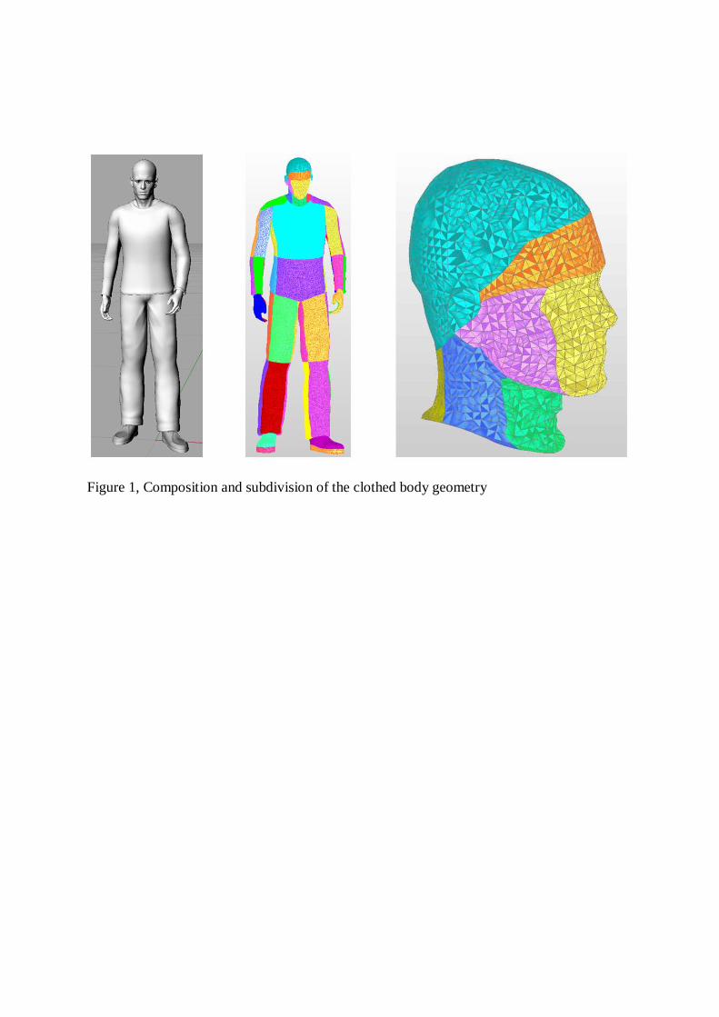
Figure 1, Composition and subdivision of the clothed body geometry

Figure 2, The clothed body geometry within the CFD mesh
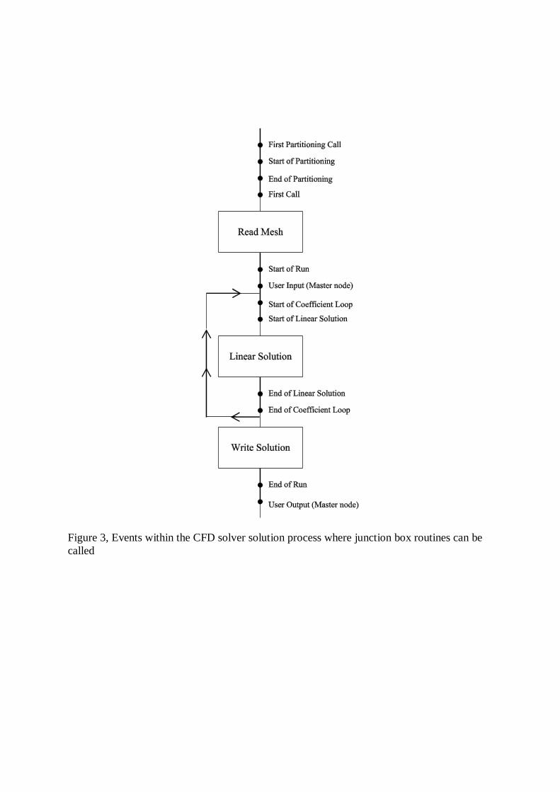
Figure 3, Events within the CFD solver solution process where junction box routines can be
called

Figure 4, The model data exchange process

Figure 5, Predicted air speed around the body (left-hand legend) and predicted body surface
temperatures (right-hand legend)

Figure 6, Velocity plot shows the thermal plume above the body

Figure 7, Predicted air temperatures around the body (left-hand legend) and predicted body
surface temperatures (right-hand legend)