coupler and tuners · pdf file · 2017-07-09using flanges and rf gaskets. ......
TRANSCRIPT

Coupler and tuners

Coupler functions
• Inject RF power generated by the RF source intothe cavity and beam,
• Maximize power transmission at the nominal frequency f0 ( or eqv. minimizing reflection ),
• Form a vacuum boundary for the cavity• From a thermal interface between the cavity and
room temperature conditions ( especiallyimportant in the case of superconductingcavities)
• Other couplers (HOM couplers) are designed to couple the high order modes out of the cavity
G.devanz CEA-Saclay CAS Bilbao may 2011 2

Coupler port location
Acceleratingstructures
Coupling port location
Coupler type Coupling type
Elliptical SC cavity Beam pipe Coaxial or waveguide electric
Spoke SC cavity Outer cylinder Coaxial electric
DTL Outer cylinder waveguide magnetic
RFQ Outer cylinder Waveguide or loop magnetic
Half wave Half plane or top Coaxial or loop Electric of magnetic
Quarter wave Bottom plate Coaxial electric
QWR
Elliptical
Spoke
HWR
G.devanz CEA-Saclay CAS Bilbao may 2011 3
Achieve the correct Qext for beam matching
Standard waveguides
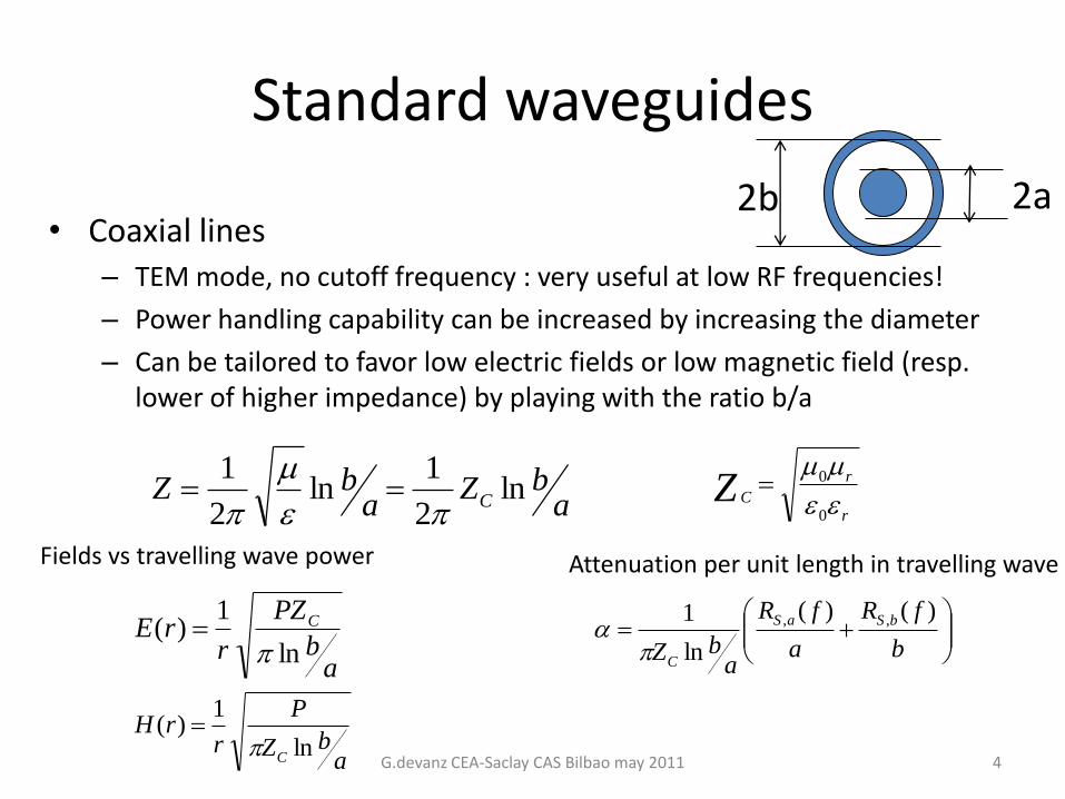
• Coaxial lines– TEM mode, no cutoff frequency : very useful at low RF frequencies!
– Power handling capability can be increased by increasing the diameter
– Can be tailored to favor low electric fields or low magnetic field (resp. lower of higher impedance) by playing with the ratio b/a
2b 2a
abZ
abZ C ln
2
1ln
2
1
r
r
CZ
0
0
Fields vs travelling wave power
ab
PZ
rrE C
ln
1)(
abZ
P
rrH
C ln
1)(
b
fR
a
fR
abZ
bSaS
C
)()(
ln
1 ,,
Attenuation per unit length in travelling wave
G.devanz CEA-Saclay CAS Bilbao may 2011 4
Standard waveguides (cont’d)
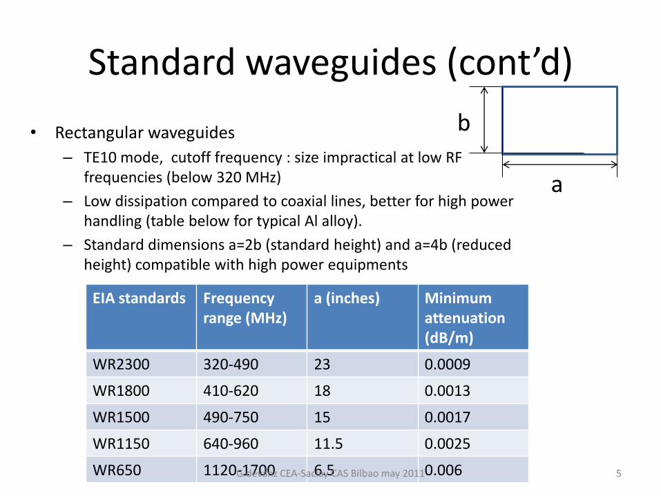
• Rectangular waveguides
– TE10 mode, cutoff frequency : size impractical at low RF frequencies (below 320 MHz)
– Low dissipation compared to coaxial lines, better for high power handling (table below for typical Al alloy).
– Standard dimensions a=2b (standard height) and a=4b (reducedheight) compatible with high power equipments
b
a
EIA standards Frequencyrange (MHz)
a (inches) Minimum attenuation(dB/m)
WR2300 320-490 23 0.0009
WR1800 410-620 18 0.0013
WR1500 490-750 15 0.0017
WR1150 640-960 11.5 0.0025
WR650 1120-1700 6.5 0.006G.devanz CEA-Saclay CAS Bilbao may 2011 5
Mode converters
• In many cases, need to carry high power efficientlywith retangular WGs, but use a coaxial coupler
• The mode converter couples the TE mode of the rectangular WG to the TEM mode of the coaxial part.
• Several solution exist– Antenna transitions
– Doorknob transition
– T-bar
– Stepped transformer
– …
G.devanz CEA-Saclay CAS Bilbao may 2011 6

DoorknobFull height WR 1150 waveguide to 100 mm 50 Ohms coaxial line
• Mechanical tolerances and bandwidth• If the doorkonb operates at atmospheric pressure the reduction of peak electric field is even more important in order to prevent arcs (E < 30 kV/cm)
Design issues
Short-circuitplate
doorknob
G.devanz CEA-Saclay CAS Bilbao may 2011 7

Air doorknob
Short-circuitplate
Cooling access
Can be built in several parts assembledusing flanges and RF gaskets. This allowssome geometrical tolerances to be met more easily:• less welds and deformations• re-machining (or shimming) at someflange for final adjustment combined withRF measurement of the device (e.g. short-circuit plate)
Provides easy acces for cooling the inner conductor of the coaxial part of the window
Can be built completely built out of Aluminum except the antenna (same as standard WGs), unless high average power requires a reduction of losses and the use of copper parts (e.g. knob)
G.devanz CEA-Saclay CAS Bilbao may 2011 8

4 parts :machined Al knobWelded Al Waveguide (1150)+short plateCu antennaAl coaxial outer conductor
Air Doorknob
G.devanz CEA-Saclay CAS Bilbao may 2011 9
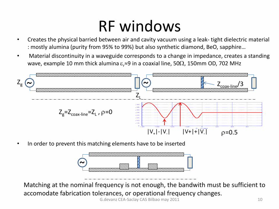
• Creates the physical barried between air and cavity vacuum using a leak- tight dielectric material: mostly alumina (purity from 95% to 99%) but also synthetic diamond, BeO, sapphire…
• Material discontinuity in a waveguide corresponds to a change in impedance, creates a standing wave, example 10 mm thick alumina r≈9 in a coaxial line, 50W, 150mm OD, 702 MHz
• In order to prevent this matching elements have to be inserted
RF windows
Zg=Zcoax-line=ZL , r=0
Zcoax-line/3Zg
ZL
Matching at the nominal frequency is not enough, the bandwith must be sufficient to accomodate fabrication tolerances, or operational frequency changes.
|V+|+|V-||V+|-|V-| r=0.5
G.devanz CEA-Saclay CAS Bilbao may 2011 10

RF windows
0
0.02
0.04
0.06
0.08
0.1
0.12
-15 -10 -5 0 5 10 15C
ha
mp
éle
ctr
iqu
e (
MV
/m)
position centrée sur la céramique (cm)
facteur 1.8
0.0001
0.001
0.01
0.1
600 650 700 750 800
fenetre TW
S11
Superfish
S11
modèle analytique
S11
f (MHz)
22/06/99
Longitudinal position
E (MV/m) inner conductor|r|
Matching options are very diverse (entire books on the subject of discontinuities in WG)Using a semi analytical model helps finding solutions with enhanced properties like the TW window (Kazakov) with a reduction of E in the ceramic disk
G.devanz CEA-Saclay CAS Bilbao may 2011 11

Waveguide window500 MHz window (Cornell)
Is used as the window of a waveguide coupler
G.devanz CEA-Saclay CAS Bilbao may 2011 12

Conical window
First versions of the TTF coupler (1.3 GHz) fromFNAL
G.devanz CEA-Saclay CAS Bilbao may 2011 13

Cylindrical windowSPL-CERN 704 MHz couplerDESY ttf coupler
G.devanz CEA-Saclay CAS Bilbao may 2011
80 K window
14

Coaxial disk windows
KEK design adapted to 704 MHz • 50 Ohms• 100 mm OD• RF matching is done using chokes
(inner and outer conductor)• Measured bandwidth @ -30 dB :
200 MHz
E HInstrumentation ports (electronprobe, arc detector)
Coolingchannels
G.devanz CEA-Saclay CAS Bilbao may 2011 15

Coaxial disk windows brazingThe brazing process between Alumina and copper requires
• a brazing compound working below copper melting point (ex. gold based),
• Specific machining of the ceramic to insert the brazing compound (wire or foil)
• Proper surface preparation of ceramic interface (MoMn)
• tooling to ensure the gaps between the parts are compatible with the thermal cycle in the oven, differential thermal expansion of materials, the quantity of braze material
• and copper parts with mechanical compliance : during cooldown, the copperinner conductor shrinks more than the ceramic, this time with a solidified braze. Alumina has a small resistance to elongation ( in contrast to its high resistanceto compression) and fails if the copper tube is too thick
The final braze joint must be homogenous, free of solidified braze droplets or run-outs (especially on the alumina disk), and vacuum tight.
G.devanz CEA-Saclay CAS Bilbao may 2011 16

Thermal aspects of couplers• Heating generated by RF
– Resistive losses on RF boundaries: use copper coating on vacuum parts ( thickness 3 to 5 times the skin depth d )
– Dielectric losses in the window material
• Resulting mechanical stress
– Thermal expansion of metallic boudaries is non uniform (different materials, local heating, non uniform cooling)
– Dielectic losses in the coupler ceramics are never uniform, interna stress occur. FEM analysis is required to look at the complete load case ( pressure+thermo-mecanical)
S
Sohmic dSHRP 2
2
1
d
10 f
RSSurface resistance Rs
Conductivity
V
rdiel dVfEtgP 2
0 22
1d
'
''
d tgwith
Not the same ‘delta’ as the skin depth !
the dielectric loss tangent, ''' j
Typical values for tg d in alumina used for windows is 10-4 to 5 10-4
G.devanz CEA-Saclay CAS Bilbao may 201117

Thermal aspects of couplers• Heat conduction to a SC cavity
– Heat leak from 300 K to LHe temperature must be minimized.
– For low average power : use thin stainless steel coupler walls, with thermal intercepts, bellows
– For high average power : use active He cooling
• Heat radiation to a SC cavity
– Coaxial coupler with single window: radiation of room temperature antenna on the cavity and the coupler outer conductor : lower the emissivity of copper surfaces (polished surface finish, electropolishing)
• The sum of above contributions are static losses (RF is off)
DESY TTF-3 coupler : 2 RF windows, heat leak fully minimized, (bellows, thin walls, 80K and 5K thermal intercepts…)Only 60mW static losses at 2K
Coldwindow
300K window
2K cavity flange
cryomoduleflange
80K intercept
G.devanz CEA-Saclay CAS Bilbao may 2011 18

Full power coupler
100 mm outer diameter50 W
He cooled outer conductor
electropolishedwater cooled inner conductor
RF window
doorknob(air)
vacuumgauge
cryostat flange
CEA-Saclay 1 MW coupler for pulsed proton linacs
G.devanz CEA-Saclay CAS Bilbao may 2011
Same general layoutas SNS coupler
19

Single window CEA coupler cooling
Vacuum side
Outer conductor (OC) He cooled
Internal conductor (IC) water cooled
ceramic outer water cooling channel
Air side
blown air on the ceramic
IC also water cooled
Air
inlet
Water
inlet
Water
outlet
Air
outlet
4.5K He
inlet
300 K He
outlet
2K
bath
Water circuit
G.devanz CEA-Saclay CAS Bilbao may 2011 20

Window in transition power coupler
Adjustable coupler (60 mm antenna stroke, factor
20 on Qext
Cylindrical
window
HV bias
Antenna drive
Antenna inner conductor is a copper tube cooled
by forced air
A Reduced height waveguide provides matching
to the coaxial line
To suppress multipactor during operation two DC
bias levels are applied
LHC 400 MHz 300 kW CW coupler
Double
walled
Stainless
steel tubeE. Montesinos
G.devanz CEA-Saclay CAS Bilbao may 2011

DTL coupler
Linac4 DTL slot coupler
Vacuum part : mechanical stiffening and cooling are necessary
Linac4 slot coupler waveguide part
before Cu plating
P.-E. Bernaudin
J. –M. De Conto
G.devanz CEA-Saclay CAS Bilbao may 2011 22

Multipacting (MP)This parasitic phenomenon occurs in vacuum RF devices when :
•Electron (initially emitted from the surface of residual gas) have resonant
trajectories (at given power levels)
•Their impact energy on the surface is such that secondary emission occurs
•The material of the surface has a secondary emission yield (SEY) greater than 1
The result is an increase of the population of electron participating to the
resonance, absorbing RF power, or creating a short-circuit in the device,
preventing normal operation
-0.5
0
0.5
1
1.5
2
2.5
3
0 500 1000 1500 2000
Secondary emission coefficient for Nb
d after wet treatmentd baked out at 300° Cd after gas discharge,
cleaned with Ar
d af
ter w
et tr
eatm
ent
incident electron energy [eV]
This happens in cavities and couplers
Cu and Alumina are critical materials for secondary emission
MP occuring on a ceramic can build up charges on the surface, leading to
breakdown. G.devanz CEA-Saclay CAS Bilbao may 2011 23

1014
1015
1016
1017
1018
1019
1020
1021
1022
0 200 400 600 800 1000
highest simulated barriers (upstream)
ma
x e
lectr
on
cou
nt
MultipactingMP in coaxial lines is well modeled (many 2D simulation codes)
Also scaling laws:
0
0.5
1
1.5
2
2.5
0 200 400 600 800 1000
measured electron signal (upstream)
e-
pic
kup
sig
na
l (V
)
RF power (kW) 20
25
30
35
40
45
50
55
16 16.2 16.4 16.6 16.8 17 17.2 17.4
r (m
m)
z (mm)
2 points MP
1.3 GHz coaxial line 50 Ohms 60 mm OD
RFTW
Resonant trajectory with 2-surface impact
Coaxial line 100 mm OD 50 Ohm
• 1 point P (f d) 4 Z
• 2 points P (f d) 4 Z2
• …
G.devanz CEA-Saclay CAS Bilbao may 2011 24

MP cures
• Design a MP free coupler
• Reduce the SEY of materials (e.g. TiN deposition on Alumina windows)
• Bias the antenna of the coupler to modify the electron trajectories and
prevent it to occur during machine operation (this happened for LEP). HV
in the 2-5 kV range is needed, so a special capacitor has to be designed.
Most of the power coupler designs include this option.
• remark : MP can be useful to clean the surfaces of the coupler
DESY TTF-3 HV capacitor
G.devanz CEA-Saclay CAS Bilbao may 2011 25

Coupler conditioning
• Conditioning is both a necessary RF/vacuum cleaning process and a validation process
• A coupler is expected to experience the full range of its power on the final machine. It also needs to sustain the full reflection of power from the cavity regardless of its detuning. During conditioning it has to go through all this and then some.
• Several interpretations of the sentence ‘the coupler is conditionned’ among the people involved…
• A strict interpretation:
IF– No more outgassing occurs on the full range of power, in traveling wave (TW) and standing wave
mode (SW) (p of the order of 10-9 mbar)
– And the coupler sustains the maximum power over long time periods (several hours in a row)
The coupler is conditioned
• A widespread conditioning strategy :– Start with TW, short pulses and ramp the power from 0 to Pmax
– Increase pulse length up to nominal one, or CW, repeat the power ramp at each stage
– Repeat the process in SW, moving the SW pattern at each stage in order to scan to whole surface of the coupler with the highest peak fields
– Perform a long term run at constant maximum power
• Conditioning can be automated– Vaccum feedback loop controls the increase of power (LHC setup)
– Interlocks shut down RF power in case of specific events (electron activity, arc detection, pressure above threshold)
G.devanz CEA-Saclay CAS Bilbao may 2011 26

Travelling wave setups
• A pair of couplers are required for TW conditioning, both connected
to a specially designed cavity, or connected through a suitable piece
of waveguide.
• The coupling coefficient to this cavity must be high enough that the
losses in the cavity are small (no energy stored)
• The cavity must no be the system limitation, so it has to be carefully
designed with respect to peak fields, multipactor, and vacuum
LHCJ-Parc
SNS
G.devanz CEA-Saclay CAS Bilbao may 2011 27

Coupler preparation in clean room
Couplers for SC cavities must be
prepared in the same cleanliness
conditions as the cavities.
• clean room assembly
• dry vacuum pumps
• dry and filtered nitrogen, slow
venting
CEA-Saclay 704 MHz couplers
G.devanz CEA-Saclay CAS Bilbao may 2011 28

Tuners
29G.devanz CEA-Saclay CAS Bilbao may 2011

What are tuners for?
• Correct the static frequency – Actual geometry differs from the theoretical one
• Temperature is different than foreseen
• The cavity experiences deformations in its normal operating environment, which were not fully known at the design stage (external pressure, supports or mechanical parts with different expansion coefficients)
• Fabrication errors (mechanical tolerances)
• Surface treatments (Nb cavities) or deposition have modified the cavity ‘volume’ differently than predicted
– Lorentz detuning (electromagnetic radiation pressure)
– Need to adapt the frequency to beam operation• Change the tuning angle for beam loading as current changes
• Reduce the beam-cavity interaction in case of a faulty component,
• ‘switch off’ a cavity for machine calibration purposes ( commissioning : cavity phase scans, time of flight)
• Compensate for fast variations – Dynamic Lorentz detuning (pulsed RF) – timescale 1 ms
– Microphonics – timescale 10 ms – 10 s
Or why would we like to change the frequency of a cavity?Material |DL/L|
273K-4K
(%)
Nb 0.13
Ti 0.13
Stainless
steel
0.27
Cu 0.3
G.devanz CEA-Saclay CAS Bilbao may 2011 30
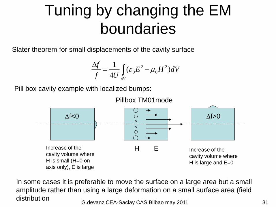
Tuning by changing the EM
boundaries
Pill box cavity example with localized bumps:
Slater theorem for small displacements of the cavity surface
Df<0 Df>0
Pillbox TM01mode
Increase of the
cavity volume where
H is small (H=0 on
axis only), E is large
Increase of the
cavity volume where
H is large and E=0
In some cases it is preferable to move the surface on a large area but a small
amplitude rather than using a large deformation on a small surface area (field
distribution
D
V
dVHEUf
f
d
)(4
1 2
0
2
0
EH
G.devanz CEA-Saclay CAS Bilbao may 2011 31

Cooling system
• Obvious solution for room temperature cavities, but limited in range: linear thermal expansion coefficients of the order of 1.710-5 (Cu and stainless steel).This means +1°C shifts a 1GHz cavity frequency by 1.7kHz if the whole cavity is expanding freely (not much in the case of a QL of 1000, to be compared to a bandwidth of 1MHz)
• Water cooling systems have a single (and only adjustable in a small range) temperature and each cavity has its individual frequency. In this setup the variable is the flow in the cavity cooling channels (and a flow controller for each cavity). The water flow settings change with power dissipated in the cavities (depending both on field level and frequency itself…)
• Multiple cooling channels can act on different parts of the cavity, and have different effects on the frequency (4-vanne RFQ)
• Not so obvious in fact, can even be unstable
G.devanz CEA-Saclay CAS Bilbao may 2011 32
Plunger tuner
• Extensively used for room temperature cavities.
• Require a flexible element– bellow : large stroke
– Flex plate : small stroke
• Warning: the side effect of using a coaxial geometry for plungers creates a RF coupler (short circuited). This is a coupled cavity (quarter wave). By changing the length of the inner conductor ( bellow plungers) the plunger resonant frequency is swept. If it crosses the cavity frequency, high losses are likely to occur in the plunger. There are cures:– Use several sections with different impedances to change the
resonant behavior,
– Reduce the stroke and use several plungers
33

Deformation tuners
• Their use is restricted to cavities built from sheet-material with a sufficient elastic range (plastic deformation is used after fabrication to adjust frequency and field distribution in many cavities)
• Mainly used for superconducting cavities– Quarter wave resonators acting on the E-field region
– Elliptical cavities (bellow-like shape): change the cavity length
• Activated by a stepper motor or pneumatic action
G.devanz CEA-Saclay CAS Bilbao may 2011 34

3 approaches on QWRs
SC Movable
plunger
Titanium
membraneStatic
plunger
V.M. stress
transverseforce
longitudinal displacement
transverse mechanical tuner
saves longitudinal space
low stress on drift tube welds
computed tuning range ± 24
kHz at 4 K
SPIRAL-2
low beta
SPIRAL-2
high beta
TRIUMF ISAC-IIG.devanz CEA-Saclay CAS Bilbao may 2011 35
Challenges of tuners for SC
cavities
• A part or the whole tuner sits at liquid He temperature ( 1.8 to 4.5 K
in real machines) and under vacuum. This includes:
– Moving parts (gears, bearings) : solid lubrication (MoS2) and seizing
issue if different materials coexist or cooling rate is inhomogenous
– And/or flexible parts : elastic properties at low temperature
– In many designs motors have to work in the same chalenging conditions
(this was solved for space industry beforehand)
• A nice feature is the extended elastic range of Nb at LHe
temperature (y approx. 400 Mpa), generally the tuning range is
limited by the mechanical tuner.
• Some cavities are stiff, require a lot of force from the tuner (up to
tens of kN)
• The tuner needs to be much stiffer than the cavity to be efficient
• Piezo electric elements used for fast tuning have reduced stroke at
Lhe temperature (10 times less than at room temperature)
G.devanz CEA-Saclay CAS Bilbao may 2011 36
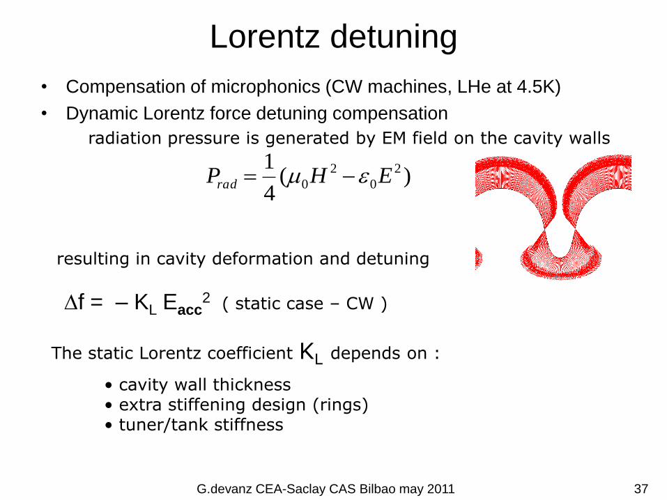
Lorentz detuning
• Compensation of microphonics (CW machines, LHe at 4.5K)
• Dynamic Lorentz force detuning compensation
)(4
1 2
0
2
0 EHPrad
Df = – KL Eacc2 ( static case – CW )
The static Lorentz coefficient KL depends on :
radiation pressure is generated by EM field on the cavity walls
resulting in cavity deformation and detuning
• cavity wall thickness• extra stiffening design (rings)• tuner/tank stiffness
G.devanz CEA-Saclay CAS Bilbao may 2011 37
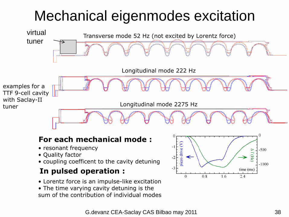
Mechanical eigenmodes excitation
Transverse mode 52 Hz (not excited by Lorentz force)
Longitudinal mode 222 Hz
Longitudinal mode 2275 Hz
examples for a TTF 9-cell cavitywith Saclay-II tuner
For each mechanical mode : • resonant frequency• Quality factor• coupling coefficent to the cavity detuning
In pulsed operation :
• Lorentz force is an impulse-like excitation• The time varying cavity detuning is the sum of the contribution of individual modes
virtual
tuner
G.devanz CEA-Saclay CAS Bilbao may 2011 38

Blade tuner
INFN tuner for 700 MHz proton cavities
1.3 GHz version
Gear boxScrew
Lever
Piezo
actuatorblades
A bellow is located at the center of the He vessel (hidden by the blades)
The screw rotation moves the lever. The torque generated is used to rotate the
center flange with respect to the ‘fixed’ flanges. Since they are connected by blades
at an angle, longitudinal force is produced with moves apart both halves of the He
tank
‘Fixed’ flange (cannot rotate)center flange
(rotates)
39
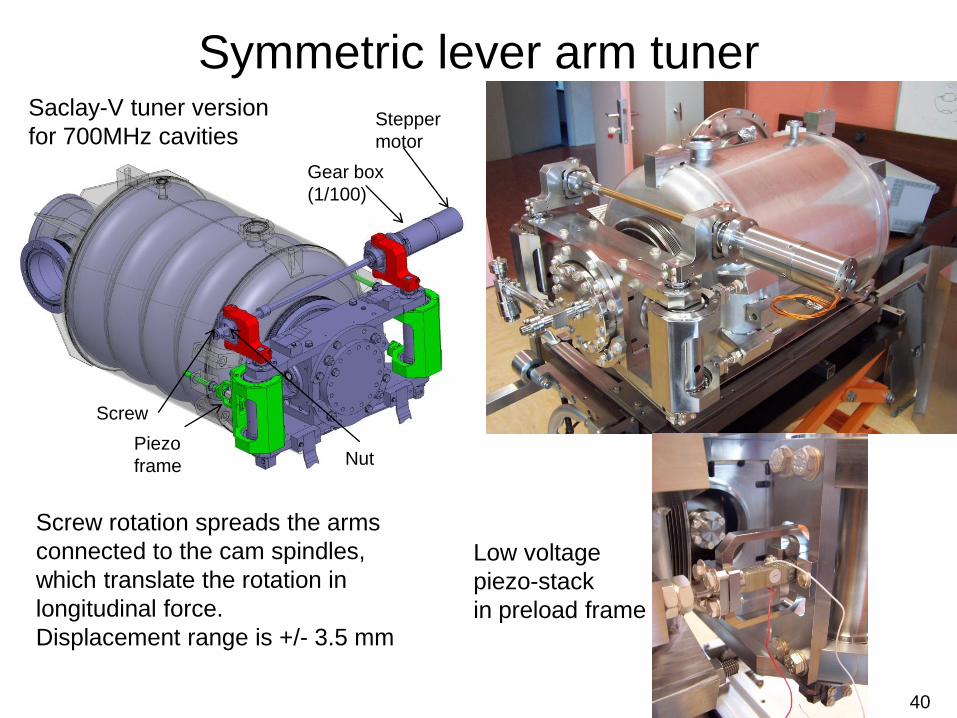
Symmetric lever arm tuner
Low voltage
piezo-stack
in preload frame
Stepper
motor
Gear box
(1/100)
Screw
Nut
Screw rotation spreads the arms
connected to the cam spindles,
which translate the rotation in
longitudinal force.
Displacement range is +/- 3.5 mm
Saclay-V tuner version
for 700MHz cavities
Piezo
frame
40

Tuner linearity
41
Motor steps
Frequency
Linearity: the tuner is efficient, does not experience deformation
Hysteresis : friction, play
Approx.
6000 N

Lorentz detuning compensation (off)
0 2 4 6 8 10 120
0.5
1
1.5
2x 10
4
Time (ms)
Ant
enna
Mag
(bi
ns)
0 2 4 6 8 10 12
-100
0
100
Time (ms)
Ant
enna
Pha
se (
deg)
0 2 4 6 8 10 120
2000
4000
6000
8000
Time (ms)
Cav
FW
D M
ag (
bins
)
0 2 4 6 8 10 12
-100
0
100
Time (ms)
Cav
FW
D P
hase
(de
g)
0 2 4 6 8 10 120
2000
4000
6000
8000
Time (ms)
Cav
RF
L M
ag (
bins
)
0 2 4 6 8 10 12
-100
0
100
Time (ms)
Cav
RF
L P
hase
(de
g)
0 2 4 6 8 10 120
2000
4000
6000
8000
Time (ms)
Kly
FW
D M
ag (
bins
)
0 2 4 6 8 10 12
-100
0
100
Time (ms)
Kly
FW
D P
hase
(de
g)
Cavity beta 0.47 : Eacc=13 MV/m
RF: Repetition frequency = 50Hz, pulse length 2ms
Piezo offamplitude phase
G.devanz CEA-Saclay CAS Bilbao may 2011 42

0 2 4 6 8 10 120
0.5
1
1.5
2x 10
4
Time (ms)
Ant
enna
Mag
(bi
ns)
0 2 4 6 8 10 12
-100
0
100
Time (ms)
Ant
enna
Pha
se (
deg)
0 2 4 6 8 10 120
2000
4000
6000
8000
Time (ms)
Cav
FW
D M
ag (
bins
)
0 2 4 6 8 10 12
-100
0
100
Time (ms)
Cav
FW
D P
hase
(de
g)
0 2 4 6 8 10 120
2000
4000
6000
8000
Time (ms)
Cav
RF
L M
ag (
bins
)
0 2 4 6 8 10 12
-100
0
100
Time (ms)
Cav
RF
L P
hase
(de
g)
0 2 4 6 8 10 120
2000
4000
6000
8000
Time (ms)
Kly
FW
D M
ag (
bins
)
0 2 4 6 8 10 12
-100
0
100
Time (ms)
Kly
FW
D P
hase
(de
g)
Piezo ON
amplitude phase
LFD Compensation achieved setting manually signal
generators driving the piezo actuator. The piezo drive
signal starts 940 s before the RF pulse (Saclay-V)
Lorentz detuning compensation (on)
G.devanz CEA-Saclay CAS Bilbao may 2011 43