countries’ i&n colombia - eneldistribuicao.com.br · mv pole mounted switch-disconnectors...
TRANSCRIPT
GLOBAL STANDARD Page 1 of 38
MV POLE MOUNTED SWITCH-DISCONNECTORS GSCM003
Rev. 00 21/01/2016
Copyright 2016. All rights reserved.
MV POLE MOUNTED SWITCH-DISCONNECTORS
This document is intellectual property of Enel SpA; reproduction or distribution of its contents in any way or by any means whatsoever is subject to the prior approval of the above mentioned company which will safeguard its rights under the civil and penal codes.
Countries’ I&N Elaborated by
Argentina E. Klymenko
Brazil V. Carvalho Robadey
Chile H. Herrera Sepúlveda
Colombia L. Vargas Rodriguez
Iberia J. Gonzalez Cortizo
Italy D. Lamanna
Peru R. Sánchez
Romania M. Domnicu / F. Dobre
Elaborated by Verified by Approved by
Solution Development Center D. Lamanna L. Giansante A. Cammarota
Global I&N – NT/NCS - N. Cammalleri G. Egea Brufau F. Giammanco
Revision Data List of modifications 00 21/01/2016 First emission
GLOBAL STANDARD Page 2 of 38
MV POLE MOUNTED SWITCH-DISCONNECTORS GSCM003
Rev. 00 21/01/2016
Copyright 2016. All rights reserved.
INDEX
1. SCOPE 5
2. APPLICATION FIELD 5
3. LIST OF COMPONENTS 5
4. REFERENCE LAWS AND STANDARDS 6
4.1 Laws 6
4.1.1 Brazil 6
4.1.2 Chile 6
4.1.3 Colombia 6
4.1.4 Iberia 6
4.1.5 Italy 6
4.1.6 Peru 7
4.1.7 All European Countries 7
4.2 Standards 7
4.2.1 Common international standards 7
4.2.2 Common technical specifications 7
4.2.3 Particular technical specifications 7
5. SERVICE CONDITIONS 8
6. COMMON CHARACTERISTICS 8
6.1 Characteristics of the switch-disconnector 8
6.2 Rated characteristics 9
6.3 SF6 10
6.4 Voltage transformer 10
6.5 Bracket 11
6.5.1 Colombia 11
6.5.2 Chile 11
6.5.3 Iberia 11
6.5.4 Italy and Peru 11
6.6 Operating directions and switch-disconnector’s comm ands 12
6.7 Devices and signal position 12
6.8 Earth connections 13
6.9 Protective coating 13
7. SWITCH-DISCONNECTOR FOR BARE CONDUCTOR LINES 14
7.1 Manual command 14
7.2 Motorised command 15
7.3 Insulators 15
GLOBAL STANDARD Page 3 of 38
MV POLE MOUNTED SWITCH-DISCONNECTORS GSCM003
Rev. 00 21/01/2016
Copyright 2016. All rights reserved.
7.4 End fitting 16
7.4.1 Italy and Romania 16
7.4.2 Brazil 16
7.4.3 Argentina, Chile, Colombia, Iberia and Peru 16
8. SWITCH-DISCONNECTOR FOR CABLE LINES 16
8.1 Manual command 18
8.2 Motorised command 18
8.3 Bushings 18
8.4 Earthing switches 18
9. MANOMETER 19
10. NAMEPLATES 19
10.1 Rating plate 19
11. MAINTENANCE 19
12. EQUIPMENT 19
13. EXCEPTION TO THIS SPECIFICATION 20
14. TESTING 20
14.1 Type tests 20
14.1.1 Visual inspection 20
14.1.2 Dielectric tests 20
14.1.3 Partial discharge test 20
14.1.4 Measurement of the main circuit resistance 21
14.1.5 Temperature-rise test 21
14.1.6 Short-time withstand current and peak withstand current tests 21
14.1.7 Control of the degree of protection (IP) 21
14.1.8 Tightness tests 21
14.1.9 Tests to verify the tightness with the repeated temperature variations 21
14.1.10 Additional test on auxiliary and control circuits 22
14.1.11 Making and breaking tests 22
14.1.12 Mechanical endurance test 23
14.1.13 Pressure withstand test for gas-filled compartments 23
14.1.14 Tests for organic material insulating elements 23
14.1.15 Verification of the protection against rust 24
14.1.16 Internal arc test 24
14.1.17 Verification of switch-disconnector and earthing switches’ safe devices 24
14.1.18 Mechanical strength test 24
14.1.19 Test of the kinematic chain in an abnormal working condition 24
14.1.20 Tests for the verification in humid atmosphere 25
GLOBAL STANDARD Page 4 of 38
MV POLE MOUNTED SWITCH-DISCONNECTORS GSCM003
Rev. 00 21/01/2016
Copyright 2016. All rights reserved.
14.1.21 Tests to verify the effectiveness of the protection against pollution 26
14.2 Additional type tests for switch-disconnectors with electrical command DC 24 V cc 26
14.2.1 Verification of the auxiliary circuits connections 26
14.2.2 Dielectric tests 26
14.2.3 Verification of electrical interlocks functioning 26
14.2.4 Mechanical operation tests with electrical command 27
14.2.5 Characteristics of the electrical command 27
14.2.6 Interruption and subsequent electrical operating completion 28
14.2.7 Interruption and subsequent manual operating completion 28
14.2.8 Verification of the enclosures’ degree of protection 28
14.3 Routine tests 28
14.3.1 Visual inspection 28
14.3.2 Dielectric test on main circuit 28
14.3.3 Tests on auxiliary and control circuits 28
14.3.4 Measurement of the resistance of the main circuit 28
14.3.5 Mechanical operation tests 28
14.3.6 Partial discharge measurement 28
14.3.7 Tightness tests 28
14.4 Additional routine tests for switch-disconnectors w ith electrical command DC 24 V cc 28
14.4.1 Verification of auxiliary circuits connections 29
14.4.2 Dielectric tests 29
14.4.3 Verification of electrical interlocks functioning 29
14.4.4 Mechanical operation tests on the electrical command 29
14.4.5 Characteristics of the electrical command 29
14.4.6 Interruption and subsequent electrical operating completion 29
14.4.7 Interruption and subsequent manual operating completion 29
14.4.8 Verification of the enclosures’ degree of protection 29
14.5 Routine tests plan 29
ANNEX A 35
ANNEX B 36
ANNEX C 37
GLOBAL STANDARD Page 5 of 38
MV POLE MOUNTED SWITCH-DISCONNECTORS GSCM003
Rev. 00 21/01/2016
Copyright 2016. All rights reserved.
1. SCOPE
The scope of this document is to provide the technical requirements for the supply of SF6 insulated MV pole mounted switch-disconnectors to be used in overhead bare conductors lines (SDL) and cable lines (SDC) of the Enel Group Distribution companies whose Countries are listed below:
• Argentina • Brazil • Chile • Colombia • Iberia • Italy • Peru • Romania
2. APPLICATION FIELD
The MV pole mounted switch-disconnectors are outdoor installation switch-disconnectors capable of operating normally, carrying their rated normal current, making and breaking their rated current, in systems with isolated neutral, resonant neutral, solidly or impedance earthed neutral.
The switch-disconnector for bare conductors (including covered conductors) shall have a motorised (or manual) command, whereas the switch-disconnector for cable lines shall have a motorised (or manual) command for opening and closing the line and a manual command for the earthing switches.
3. LIST OF COMPONENTS
The following components are covered by this global standard:
Type code Description Typology Command
type
Rated normal current
[A]
Rated short-circuit
breaking current [kA]
Rated voltage [kV]
Creepage distance
[mm]
GSCM003/1 SDL-M24 Bare conductors
Manual
630 16 24
744 GSCM003/2 SDL-E24 Electrical
GSCM003/3 SDL-M24P Bare conductors
extreme pollution
Manual 835
GSCM003/4 SDL-E24P Electrical
GSCM003/5 SDC-M24 Cable lines
Manual
GSCM003/6 SDC-E24 Electrical
Table 1: List of components (24 kV)
GLOBAL STANDARD Page 6 of 38
MV POLE MOUNTED SWITCH-DISCONNECTORS GSCM003
Rev. 00 21/01/2016
Copyright 2016. All rights reserved.
Type code Description Typology Command
type
Rated normal current
[A]
Rated short-circuit
breaking current [kA]
Rated voltage [kV]
Creepage distance
[mm]
GSCM003/7 SDL-M36 Bare conductors
Manual
630 16 36
1116 GSCM003/8 SDL-E36 Electrical
GSCM003/9 SDL-M36P Bare
conductors extreme pollution
Manual 1250
GSCM003/10 SDL-E36P Electrical
GSCM003/11 SDC-M36 Cable lines
Manual
GSCM003/12 SDC-E36 Electrical
Table 2: List of components (36 kV)
For local components codification see Annex B.
4. REFERENCE LAWS AND STANDARDS
4.1 Laws
4.1.1 Brazil
NR-10 - segurança em instalações e serviços em eletricidade.
4.1.2 Chile
NSEG 5. E.n.71 - Reglamento de Instalaciones Eléctricas de Corrientes Fuertes.
4.1.3 Colombia
RETIE - Reglamento Técnico de Instalaciones Eléctricas.
Ley 400 de 1997 - Reglamento Colombiano de Normas sismo-resistentes.
4.1.4 Iberia
R.D. 614/2001, de 8 de junio, sobre disposiciones mínimas para la protección de la salud y seguridad de los trabajadores frente al riesgo eléctrico.
R.D. 337/2014, de 9 de mayo, por el que se aprueban el Reglamento sobre condiciones técnicas y garantías de seguridad en instalaciones eléctricas de alta tensión y sus Instrucciones Técnicas Complementarias ITC-RAT 01 a 23.
R.D. 223/2008, de 15 de febrero, por el que se aprueban el Reglamento sobre condiciones técnicas y garantías de seguridad en líneas eléctricas de alta tensión y sus instrucciones técnicas complementarias ITC-LAT 01 a 09.
4.1.5 Italy
D.P.R. n. 341 of the 13th of February 1981.
D.Lgs n. 81 of the 9th of April 2008 and subsequent modifications.
D.P.R. n. 43 of the 27th of January 2012.
GLOBAL STANDARD Page 7 of 38
MV POLE MOUNTED SWITCH-DISCONNECTORS GSCM003
Rev. 00 21/01/2016
Copyright 2016. All rights reserved.
4.1.6 Peru
Código Nacional de Electricidad Suministro.
4.1.7 All European Countries
Regulation (EU) of the European Parliament and of the Council 517/2014 of the 16th of April 2014.
Regulation (EC) of the Commission 1494/2007 of the 17th of December 2007.
4.2 Standards
4.2.1 Common international standards
The below listed reference documents shall be intended in the in-force edition at the contract date (amendments included). Unless otherwise specified, these documents are valid until the new editions replace them.
Standards Edition
IEC 62271-1 2007-10
IEC 62271-102 2001-12 IEC 62271-200 2011-10 IEC 60447 2004-01 IEC 60529 1989-11
EN 50181 2010-07
IEC 62271-103 2011-06
ISO 1461 2009-05
ISO 2081 2008-12
4.2.2 Common technical specifications
DY1050 - Requirements for the 24 Vcc motorisation
GSTR001 - Peripheral Unit
PVR006 - Barcode
GSCT003 - Self-protected voltage transformer
GSCT004 - Outdoor voltage transformer
GSCS006 - Bracket
4.2.3 Particular technical specifications
Unless otherwise specified, these technical specifications are valid until the new editions replace them.
4.2.3.1 Chile
ETGI-1020 - Especificaciones técnicas generales - Requisitos de diseño sísmico para equipo eléctrico.
DMAD-0184 - Poste de hormigón armado 13,5 m.
4.2.3.2 Colombia
NSR - 10 Norma Sismo Resistente Colombiana.
GLOBAL STANDARD Page 8 of 38
MV POLE MOUNTED SWITCH-DISCONNECTORS GSCM003
Rev. 00 21/01/2016
Copyright 2016. All rights reserved.
4.2.3.3 Peru
E-SE-010 - Acción sísmica en equipos eléctricos y mecánicos.
5. SERVICE CONDITIONS
Limits of the ambient temperature: Maximum temperature not higher than 50 °C with average value, referred to a 24 h period, not higher than:
35 °C
Minimum ambient air temperature for outdoor installation:
- 25 °C *
Table 3: Limits of the ambient temperature
Relative humidity (IEC 60271-2-1) 98%
Contamination level (IEC 60815) Very High (IV)
Table 4: Requirements for corrosive atmospheres
* For Romania the minimum ambient air temperature is - 40 °C.
For Colombia the maximum reference altitude is 2.700 m.
For all the other characteristics the reference is the IEC 62271-200, whereas the earthing switches shall comply with the IEC 62271-102.
6. COMMON CHARACTERISTICS
6.1 Characteristics of the switch-disconnector
The switch-disconnector has to be manufactured in compliance with the reference national laws and with the standards pointed out in section 4.2.
The enclosures must be filled with SF6 exclusively in the factory and they have to form a sealed pressure system (IEC 62271-200) 1.
The switch-disconnector must be sealed. The elements used in the factory for filling and recovering the SF6 at the end of life shall be identified with a self-adhesive plate and protected from accidental shocks. On the plate it shall be written: "Remove the cap at the end of the switch-disconnector’s operating life only for the possible recovery of gas" 2. This plate shall have a yellow RAL 1021 background and the words in black RAL 9005.
During the design and manufacturing of the switch-disconnector, strains during operation and transportation must be taken into account; to do this there must be a safety valve against overpressure. The valve shall be equipped with a metallic disc for the protection against accidental strains, placed at a proper distance from the valve itself and equipped with lateral grids which allow the gas vent and prevent the fall of material to the ground.
The valve shan’t be put in the operation sides of the switch-disconnector (e.g., motorisation side, cable side, lever side) and shall be protected against water infiltration.
1 For Italy the filling shall be made in order that the maximum operating relative pressure at 45 °C does not exceed 0,5 [kg/cm2]. 2 The plate shall be written in the language of the Country in which the component has to be delivered.
GLOBAL STANDARD Page 9 of 38
MV POLE MOUNTED SWITCH-DISCONNECTORS GSCM003
Rev. 00 21/01/2016
Copyright 2016. All rights reserved.
The switch-disconnector shall be equipped with “safe position devices” for the indication of the real position of the main moving contacts of the switches, as required by IEC 62271-200 and IEC 62271-102.
The panels for the accessing the mechanical parts of the switch-disconnector and of the earthing switches shall ensure the degree of protection IP54. These panels shall be removed for maintenance operations without removing parts of the commands; it is allowed only removing the extensions of the operating shafts of the switch-disconnector and of the earthing switches that allow the use of the earthing stick.
The switch-disconnector shall be provided with appropriate lifting eyebolts in its upper part and four M12 threaded holes in its lower part. The weight must not exceed 200 kg.
After installation, the switch-disconnector shall be oblique towards the pole of 3 degrees to avoid the stagnation of humidity.
The switch-disconnector shall comply with point 5.102 of IEC 62271-102 regarding the requirements of the isolating distance.
In the case that the switch-disconnector has an additional internal insulating shell, in alternative to the connection described in point 5.102 of IEC 62271-102, to verify the effectiveness of the protection against the pollution caused by the products of decomposition and the behaviour of its insulating material, it’s necessary to perform the test of point 6.104.2 of IEC 62271-200.
In the absence of a safe connection to earth, to verify the effectiveness of the protection against pollution in service of the insulating materials, the test of paragraph 14.1.21 of this Global Standard shall be performed.
6.2 Rated characteristics
The main characteristics are listed in table 5 below.
GLOBAL STANDARD Page 10 of 38
MV POLE MOUNTED SWITCH-DISCONNECTORS GSCM003
Rev. 00 21/01/2016
Copyright 2016. All rights reserved.
Rated voltage [kV] 24 36
Rated insulation level
- impulse withstand voltage to earth and between phases
[kV] 125 170
- impulse between the open contacts of the switch-disconnectors
[kV] 145 195
- power frequency voltage to earth and between phases
[kV] 50 70
- power frequency voltage between the open contacts of the switch-disconnectors
[kV] 60 80
Rated frequency [Hz] 50 (or 60)
Rated normal current [A] 630
Rated short-time withstand current [kA] 16
Crest value of the rated short-time withstand current [kAc] 40 (or 41,6)
Rated short-circuit duration [s] 1
External degree of protection IP54
Internal arc test current [kA] 16
Internal arc test current duration [s] 0,5
Mechanical endurance class M2
Electrical endurance class E3
Rated breaking current
- of a mainly active load [A] 630
- of a no-load transformer [A] 6,3
- of a no-load line [A] 10 13
- of a no-load cable [A] 31,5 40
- in case of earth fault [A] 50
- with cable-charging in case of earth fault [A] 16 25
Table 5: Characteristics of the switch-disconnector
6.3 SF6
The characteristics of the first filling gas shall meet the requirements of IEC 60376. The humidity content of the first filling gas shall be less than 15 ppm in weight and, during operation, the absence of condensation at the minimum operating expected temperatures must be guaranteed. The manufacturer shall ensure that at the end of the expected life of the equipment (30 years) the gas pressure remains higher than (or equal) the minimum operating pressure pm (minimum necessary pressure to ensure the performances prescribed for the device). In any case, the loss shall not exceed the 0,1% value in weight per year (IEC 62271-1).
6.4 Voltage transformer
The switch-disconnectors with motorised command shall consider an outdoor phase-to-phase voltage transformer (not to be supplied with the switch-disconnector), for giving the power supply to the Peripheral Unit, in accordance with the Global Standard GSCT003 or GSCT004.
The voltage transformer shall be put on another support on the pole on the opposite side of the switch-disconnector.
MV POLE MOUNTED SWITCH
Copyright 2016. All rights reserved.
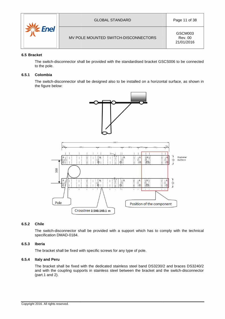
6.5 Bracket
The switch-disconnector shall be provided with to the pole.
6.5.1 Colombia
The switch-disconnector shall be designed also to be installed on a horizontalthe figure below:
6.5.2 Chile
The switch-disconnector shall be provided with a support which has to comply with the specification DMAD-0184.
6.5.3 Iberia
The bracket shall be fixed with specific screws for any type of pole.
6.5.4 Italy and Peru
The bracket shall be fixed with the dedicated stainless steel band and with the coupling supports (part.1 and 2).
GLOBAL STANDARD
MV POLE MOUNTED SWITCH-DISCONNECTORS
disconnector shall be provided with the standardised bracket GSC
disconnector shall be designed also to be installed on a horizontal
disconnector shall be provided with a support which has to comply with the
The bracket shall be fixed with specific screws for any type of pole.
with the dedicated stainless steel band DS3230/2supports in stainless steel between the bracket and the switch
Page 11 of 38
GSCM003 Rev. 00
21/01/2016
GSCS006 to be connected
disconnector shall be designed also to be installed on a horizontal surface, as shown in
disconnector shall be provided with a support which has to comply with the technical
DS3230/2 and braces DS3240/2 between the bracket and the switch-disconnector
MV POLE MOUNTED SWITCH
Copyright 2016. All rights reserved.
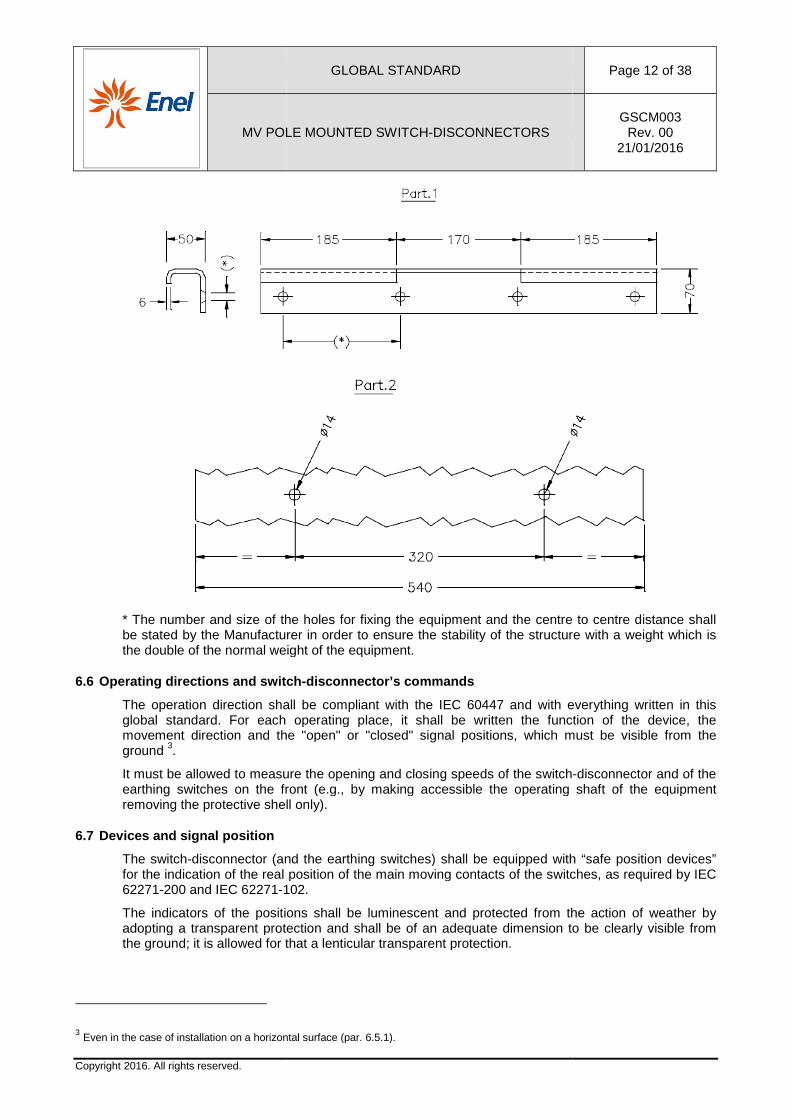
* The number and size of the holes be stated by the Manufacturer in order to the double of the normal weight of the equipment.
6.6 Operating directions and switch
The operation direction shall be compliant with the IEC 60447 and with everything written in this global standard. For each operating place, it shall be written the function of the device, the movement direction and the "open" or "cground 3.
It must be allowed to measure the opening and closing speeds of the switchearthing switches on the front (e.g., by making accessible the operating shaft of the equipremoving the protective shell only).
6.7 Devices and signal position
The switch-disconnector (and the earthing switches) shall be equipped with “safe position devices” for the indication of the real position of the main moving contacts of the switches, as62271-200 and IEC 62271-102.
The indicators of the positions shall be luminescent and protected from the action of weather by adopting a transparent protection and shall be of an adequate dimension to be clearly visible from the ground; it is allowed for that a lenticular transparent protection.
3 Even in the case of installation on a horizontal surface (par. 6.5.1).
GLOBAL STANDARD
MV POLE MOUNTED SWITCH-DISCONNECTORS
* The number and size of the holes for fixing the equipment and the centre to centre distance shall be stated by the Manufacturer in order to ensure the stability of the structure with a weight which is the double of the normal weight of the equipment.
Operating directions and switch -disconnector’s commands
The operation direction shall be compliant with the IEC 60447 and with everything written in this global standard. For each operating place, it shall be written the function of the device, the movement direction and the "open" or "closed" signal positions, which must be visible from the
It must be allowed to measure the opening and closing speeds of the switchon the front (e.g., by making accessible the operating shaft of the equip
removing the protective shell only).
disconnector (and the earthing switches) shall be equipped with “safe position devices” for the indication of the real position of the main moving contacts of the switches, as
102.
The indicators of the positions shall be luminescent and protected from the action of weather by adopting a transparent protection and shall be of an adequate dimension to be clearly visible from
t is allowed for that a lenticular transparent protection.
Even in the case of installation on a horizontal surface (par. 6.5.1).
Page 12 of 38
GSCM003 Rev. 00
21/01/2016
for fixing the equipment and the centre to centre distance shall the stability of the structure with a weight which is
The operation direction shall be compliant with the IEC 60447 and with everything written in this global standard. For each operating place, it shall be written the function of the device, the
ions, which must be visible from the
It must be allowed to measure the opening and closing speeds of the switch-disconnector and of the on the front (e.g., by making accessible the operating shaft of the equipment
disconnector (and the earthing switches) shall be equipped with “safe position devices” for the indication of the real position of the main moving contacts of the switches, as required by IEC
The indicators of the positions shall be luminescent and protected from the action of weather by adopting a transparent protection and shall be of an adequate dimension to be clearly visible from
GLOBAL STANDARD Page 13 of 38
MV POLE MOUNTED SWITCH-DISCONNECTORS GSCM003
Rev. 00 21/01/2016
Copyright 2016. All rights reserved.
Near the indicators, nameplates shall be applied. These nameplates, for "switch-disconnector" and "earthing switches”, shall be on white background with black RAL 9005 characters to facilitate their identification.
Moreover, the following indications shall be provided: • switch-disconnector’s signal position, through the following symbology 4:
• black letter “I” on 3000 RAL F2 red background corresponding to the close position of the switch-disconnector;
• black letter “O” on 6017 RAL F2 green background corresponding to the open position of the switch-disconnector;
• earthing switch’s signal position. The used device shall be mechanically interlocked with the main circuit moving contacts and the correspondent position shall be displayed through the following symbology:
• black letter “I” on 1021 RAL F2 yellow background corresponding to the close position of the earthing switch; black letter “O” on 7030 RAL F2 grey background corresponding to the open position of the earthing switch;
The signal positions shall be visible even with the protection shell removed.
6.8 Earth connections
Every metallic parts of the enclosures and/or metallic partitions and the local command shall be connected to the provided M12 earthing point. 5
The operating shafts of the switch-disconnectors and of the earthing switches and the other metallic objects must be connected to the earth with copper conductors whose section must not be less than 16 mm2.
In case of switch-disconnectors for cable lines, from the switch-disconnector earthing point a copper bar shall be derived and it shall develop above and along the entire length of the switch-disconnector and, in correspondence of the bushings, it shall be provided with three M12 bolts per side on which the earthing connections of the MV cable shields shall be fixed.
6.9 Protective coating
The enclosure of the switch-disconnector and the command cover, which has to be in stainless steel AISI 316, doesn’t need a protective coating.
The welded parts in stainless steel shall be treated with surface passivation using nitric acid or equivalent.
The parts in ferrous material of the operating commands, treated with an iridescent conversion coating or equivalent 6 (Fe/Zn12/C in compliance with ISO 2081), shall be protected by an electrolytic coating of 12 µm of zinc. The assembling nuts and bolts and the small accessories, unless otherwise specified, shall be protected with electrolytic zinc, except the external ones which must be in stainless steel.
All the external metallic parts which are not in stainless steel shall be protected with a galvanization process according to ISO 1461.
4 For Brazil the letters indicating the signal position of switch-disconnector and earthing switches shall be “D” for the open position and “L” for the close one. 5 For Italy and Romania an additional copper wire of 50 mm2 shall be provided to connect the earthing point of the switch-disconnector to the earthing point of the local command. 6 The equivalent conversion coatings shan’t show the red rust before 336 hours (as well as the hexavalent chromium).
MV POLE MOUNTED SWITCH
Copyright 2016. All rights reserved.
7. SWITCH-DISCONNECTOR FOR BAR
This component has just theelectric scheme is the one of the figure below.
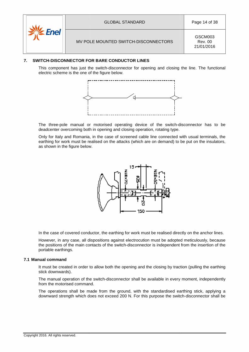
The three-pole manual or motorised deadcenter overcoming both in open
Only for Italy and Romania, iearthing for work must be realised on the attacks as shown in the figure below.
In the case of covered conductor, the earthing for work must be realised directly on the
However, in any case, all dispositions against electrocution must be adopted meticulously, because the positions of the main contacts of the switchportable earthings.
7.1 Manual command
It must be created in order to allow both the opening and the closing by traction (pulling the earthing stick downwards).
The manual operation of the switchfrom the motorised command.
The operations shall be maddownward strength which does not exceed
GLOBAL STANDARD
MV POLE MOUNTED SWITCH-DISCONNECTORS
DISCONNECTOR FOR BARE CONDUCTOR LINES
has just the switch-disconnector for opening and closing the line.electric scheme is the one of the figure below.
or motorised operating device of the switch-disconnector has to be deadcenter overcoming both in opening and closing operation, rotating type.
Only for Italy and Romania, in the case of screened cable line connected with usual terminalearthing for work must be realised on the attacks (which are on demand) to be put on the insulators,
he figure below.
In the case of covered conductor, the earthing for work must be realised directly on the
However, in any case, all dispositions against electrocution must be adopted meticulously, because the positions of the main contacts of the switch-disconnector is independent
in order to allow both the opening and the closing by traction (pulling the earthing
of the switch-disconnector shall be available in every moment, independently from the motorised command.
The operations shall be made from the ground, with the standardised eardoes not exceed 200 N. For this purpose the switch
Page 14 of 38
GSCM003 Rev. 00
21/01/2016
for opening and closing the line. The functional
disconnector has to be
n the case of screened cable line connected with usual terminals, the to be put on the insulators,
In the case of covered conductor, the earthing for work must be realised directly on the anchor lines.
However, in any case, all dispositions against electrocution must be adopted meticulously, because disconnector is independent from the insertion of the
in order to allow both the opening and the closing by traction (pulling the earthing
in every moment, independently
e from the ground, with the standardised earthing stick, applying a switch-disconnector shall be
GLOBAL STANDARD Page 15 of 38
MV POLE MOUNTED SWITCH-DISCONNECTORS GSCM003
Rev. 00 21/01/2016
Copyright 2016. All rights reserved.
operated with the earthing stick directly on a local command with a lever put at 4 ÷ 4,5 m from the base of the pole.7
The manual command shall be realised in order to allow the application of a lock with an arc of 8 mm thickness in the open and close position on the local command.
The manual operation or the lock must prevent the motorised command. The command shall be outdoor type, realised to prevent condensation.
The degree of protection of the operating devices shall be IP54.
7.2 Motorised command
The motorised command of the switch-disconnector shall allow the possibility to put the local command operated with the earthing stick, to install the VT on the opposite side of the pole, to substitute the electronic board and the electric motor in an easy way and without removing the switch-disconnector. It shall be compliant to what it’s stated in the technical specification DY1050, with the modifications listed below:
• the connection cable between switch-disconnector and Peripheral Unit, to be supplied with the switch-disconnector, shall be 10x1,5 mm2 outdoor type, 10 m long8. Both the extremities of this cable shall have pre-isolated terminals for the terminal box used and identification marks according to the connection table 10. This cable shall be prepared joining two conductors in parallel for each polarity of the power circuit, mechanically joint by a heat shrinking for a minimum length of 20 cm. Every necessary hole for cable passage shall have appropriate cable gland in order to restore the degree of protection of the shell (IEC 60529);
• The connection cable between the voltage transformer and the Peripheral Unit shall be a 2x2,5 mm2 outdoor type with a maximum external diameter of 16 mm. One of the two conductors shall have the earthing symbol at one extremity. The cable length shall be 10 m9.
7.3 Insulators
The insulators, compliant with the standard IEC 60137, shall be made of organic material resistant at the electrical environment ageing (silicone without EPDM)10; they must have a creepage distance as shown in the table below between live parts to the earth and a bending moment at the base of the attack of minimum 250 Nm and must resist at an adequate tightening torque for the conductors.
Rated voltage [kV] Minimum creepage distance [mm]
24 744 (835*)
36 1116 (1250*)
* Values of the creepage distance for extreme pollution.
7 On the switch-disconnectors to be provided in LATAM, the lever to operate the line shall be put on the enclosure on the command cover (in front of the switch-disconnector), jointly liable with the motorisation, and designed in order that they ensure the safety distance of 750 mm from live parts. 8 For switch-disconnectors to be delivered in Spain, the connection cable between switch-disconnector and peripheral unit shall be 10x2,5 mm2 and 20 m long. 9 For switch-disconnectors to be delivered in Spain, the connection cable between voltage transformer and peripheral unit shall be 20 m long. 10 For Peru the test of resistance to tracking and erosion shall be performed at the test voltage of 5 kV to 6 kV according to IEC 60587, Table 1.
MV POLE MOUNTED SWITCH
Copyright 2016. All rights reserved.
7.4 End fitting
7.4.1 Italy and Romania
The internal conductor of the insulator shall be in copper and have a diameter of 16 mm; its far end shall be threaded M16x60.
The connection between the bare conductor line and the insulator shall be made with an eyelet terminal compatible with the M16 of the far end of the internal conductor of the insulator.
7.4.2 Brazil
The far end of the internal material compatible with the terminal of the figure below.
7.4.3 Argentina, Chile, Colombia,
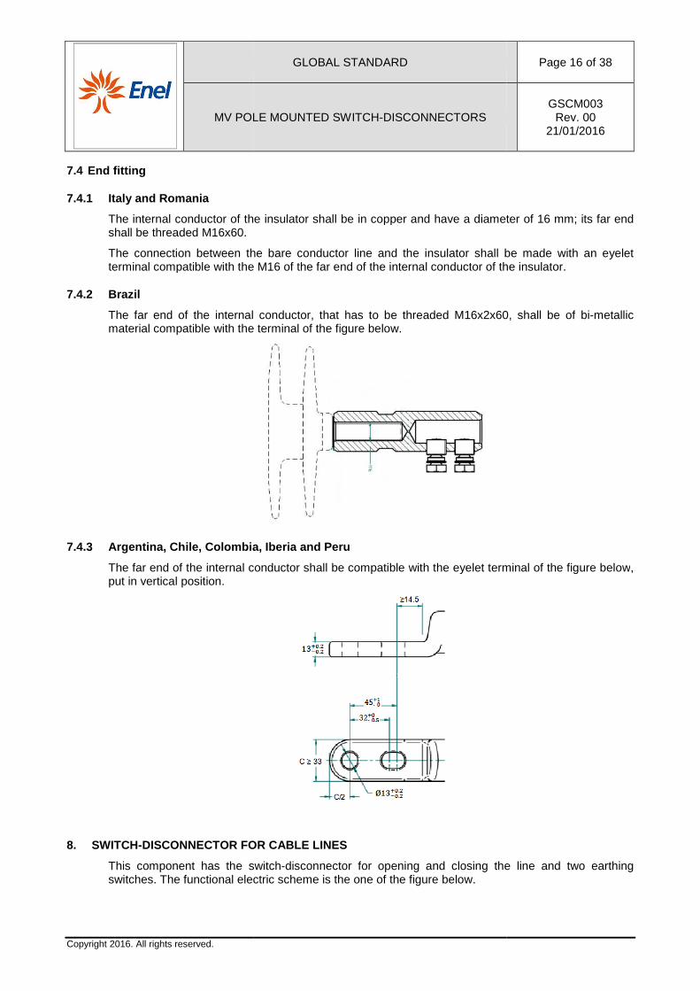
The far end of the internal conductor shall be compatible with the eyelet terminal of the figure belowput in vertical position.
8. SWITCH-DISCONNECTOR FOR CAB
This component has the switchswitches. The functional electric scheme is
GLOBAL STANDARD
MV POLE MOUNTED SWITCH-DISCONNECTORS
The internal conductor of the insulator shall be in copper and have a diameter of 16 mm; its far end
The connection between the bare conductor line and the insulator shall be made with an eyelet compatible with the M16 of the far end of the internal conductor of the insulator.
The far end of the internal conductor, that has to be threaded M16x2x60, he terminal of the figure below.
Chile, Colombia, Iberia and Peru
The far end of the internal conductor shall be compatible with the eyelet terminal of the figure below
DISCONNECTOR FOR CABLE LINES
switch-disconnector for opening and closing the line and two earthing The functional electric scheme is the one of the figure below.
Page 16 of 38
GSCM003 Rev. 00
21/01/2016
The internal conductor of the insulator shall be in copper and have a diameter of 16 mm; its far end
The connection between the bare conductor line and the insulator shall be made with an eyelet compatible with the M16 of the far end of the internal conductor of the insulator.
conductor, that has to be threaded M16x2x60, shall be of bi-metallic
The far end of the internal conductor shall be compatible with the eyelet terminal of the figure below,
for opening and closing the line and two earthing
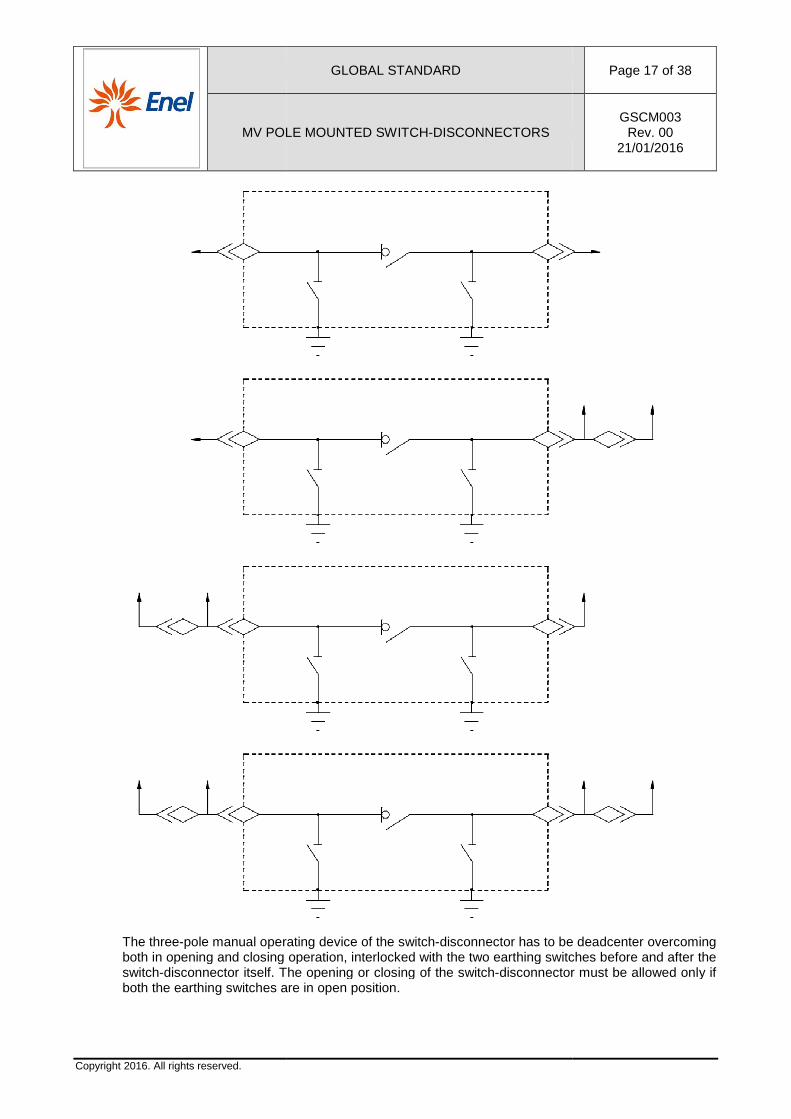
MV POLE MOUNTED SWITCH
Copyright 2016. All rights reserved.
The three-pole manual operating device of the switchboth in opening and closing switch-disconnector itself. The opening or closing of the switchboth the earthing switches are in open position.
GLOBAL STANDARD
MV POLE MOUNTED SWITCH-DISCONNECTORS
pole manual operating device of the switch-disconnector has to be deadcenter overcoming both in opening and closing operation, interlocked with the two earthing switches before and after the
disconnector itself. The opening or closing of the switch-disconnector must be allowed only if both the earthing switches are in open position.
Page 17 of 38
GSCM003 Rev. 00
21/01/2016
disconnector has to be deadcenter overcoming operation, interlocked with the two earthing switches before and after the
disconnector must be allowed only if
GLOBAL STANDARD Page 18 of 38
MV POLE MOUNTED SWITCH-DISCONNECTORS GSCM003
Rev. 00 21/01/2016
Copyright 2016. All rights reserved.
The lever of the switch-disconnector to open or close the line shall be red RAL 3026 (e.g., polyurethane paint) and shall have a nameplate with the characters “IMS” referring to the switch-disconnector in black RAL 9005 on white RAL 9010 background.
The enclosure of the switch-disconnector shall be designed to have a stainless steel AISI 316 cover on the upper side and lateral side of the bushings with a dimension of 300 mm from the border of the enclosure.
8.1 Manual command
The manual command of the switch-disconnector shall be realised in accordance with what it’s stated in paragraph 7.1, with the following modifications:
• the operations shall be made from the ground, with the standardised earthing stick, applying a strength which does not exceed 200 N. For this purpose the switch-disconnector shall be put at 6 m from the ground.
• the manual command shall be realised in order to allow the application of a lock in the open and close positions; this lock shall resist at a strength of 800 N applied at the lever in vertical direction, without causing permanent deformations.
8.2 Motorised command
See paragraph 7.2.
8.3 Bushings
To connect the MV cable terminals, the switch-disconnector shall be equipped with outdoor cone bushings in accordance with EN 50181. Bushings shall have 630 A rated normal current (type C interface). To connect the MV cable to the bushings, symmetrical T-separable connectors shall be used.
In order to avoid that the cable weight interferes with the bushing resistance, a support shall be provided on the bottom of the switch-disconnector (the support may be removable for transportation). The height between the axis of the bushing and the support shall be at least 420 mm.
The support shall have a tension clamp for each cable according to the Global Standard GSC001 to transmit the mechanical tension in the cable to the supporting structure.
8.4 Earthing switches
The earthing switches shall comply with the IEC 62271-102 and shall have the characteristics listed in table 6.
Rated short-time withstand current [kA] 16
Crest value of the rated short-time withstand current [kAc] 40 (or 41,6)
Short-circuit making capacity [kA] 40 (or 41,6)
Rated short-circuit duration [s] 1
Mechanical endurance class M0
Electrical endurance class E2
Table 6: Characteristics of the earthing switches
The two earthing switches, which are independent between them, must be moved only with the switch-disconnector in open position.
GLOBAL STANDARD Page 19 of 38
MV POLE MOUNTED SWITCH-DISCONNECTORS GSCM003
Rev. 00 21/01/2016
Copyright 2016. All rights reserved.
The levers of both the earthing switches shall be yellow RAL 1026 (e.g., polyurethane paint) and shall have a nameplate with the characters “ST1” and “ST2” in black RAL 9005 on white RAL 9010 background.
The levers may be taken away in order to remove the front panels. Their assembling must be allowed only in an obliged position, to avoid that they can be exchanged between them and with that one of the switch-disconnector. The levers shall be removed for transportation.
It shall be provided a hole to allow the application of a lock with an arc of 8 mm thickness in the open and close positions; this lock shall resist at a strength of 800 N applied at the lever in vertical direction, without causing permanent deformations.
9. MANOMETER
To measure the SF6 pressure, on the type codes to be supplied in Spain a manometer shall be provided.
The manometer shall not be extractable and, in supply normal conditions, the pressure indication shall be between 25% and 75% of the area marked as safe. The area marked as safe shall be green RAL 6017 whereas the other area shall be red RAL 3000. It must be visible from the bottom of the pole.
10. NAMEPLATES
Each switch-disconnector shall have a nameplate in the language of the Country in which it has to be delivered carved or relief printed on a long-lasting material, weather resistant and secured on the protective shell 11. This nameplate shall have four eyelets for fixing it at the base of the pole with a stainless steel band or it shall be provided with a support to put on the pole.
10.1 Rating plate
The rating plate shall contain information on the code that the Manufacturer assigns to each series of the same type. It shall contain the mandatory information required by IEC 62271-200 (table 101), such as: Manufacturer’s name, year and month of manufacture, manufacturer’s type designation, serial number, weight [kg] and pressure [Pa] of SF6, electric scheme 12.
In the proximity of the rating plate it must be put a barcode with the characteristics described in Nota Operativa Presidio Vendor Rating PVR006.
An informative nameplate with the sentence “Contains fluorinated greenhouse gases covered by the Kyoto Protocol”, in accordance with Regulation (EU) of the European Parliament and of the Council 517/2014 of the 16th of April 2014, has to be provided.
11. MAINTENANCE
The switch-disconnectors shall have a manual in accordance with the point 10.4 of IEC 62271-1, which shall include the maintenance mode to be observed (e.g., grease on some parts of the command), considering the device type and the period of time in which they have to be carried out. The switch-disconnector, for the first 36 months from its delivery date, must be maintenance free. The subsequent maintenance must have a frequency that is not less than 36 months. These statements must be written in the instruction manual.
12. EQUIPMENT
Each switch-disconnector must be equipped with:
11 For Italy and Spain two nameplates shall be provided: one on the switch-disconnector and the other one at the base of the pole. 12 For Colombia on the rating plate there shall be also the Customer’s Name.
GLOBAL STANDARD Page 20 of 38
MV POLE MOUNTED SWITCH-DISCONNECTORS GSCM003
Rev. 00 21/01/2016
Copyright 2016. All rights reserved.
• installation, operation and maintenance manual in the language of the Country in which the switch-disconnector has to be delivered;
• manual with procedures to be adopted for storage, after factory test and transportation; • a packing for transportation and storage (which does not take part in the homologation
process) according to the documents of every Country.
The insulators and the bushings shall be opportunely protected to safeguard them from impacts that may damage them. These protections shall be realised so not to have a difficult assembling and in order they can be removed only after installation.
Outside of the box containing the switch-disconnector, it shall be clearly written: • name of the Distribution Company; • name of the supplier; • description of the product; • code assigned by the supplier; • type code and serial number of the Distribution Company; • gross weight.
13. EXCEPTION TO THIS SPECIFICATION
Any exception to this technical specification, concerning the adoption of techniques and/or special construction different than what is specified in this document, may be taken into account during the homologation process. However, in this case, the Distribution Company reserves the right to prescribe the execution of additional tests other than those ones described in this document, in relation to the specific proposals.
14. TESTING
On the switch-disconnector the tests described in the following paragraphs shall be performed.
The making capability of the earthing switch and the pressure leak test, referred to point 6.101 of IEC 62271-200, shall be carried out on a switch-disconnector fully prepared to be put in service.
The tests to be performed on the switch-disconnectors are divided in: • Type tests • Routine tests.
14.1 Type tests
During tests maintenance is not allowed.
14.1.1 Visual inspection
The switch-disconnector shall be subject to a visual inspection in order to verify the absence of defects and that the construction features and the dimensions are those ones prescribed in the technical specifications. In detail, it must be verified that the characteristics are correctly shown on the rating plate, as indicated by IEC 62271-200.
14.1.2 Dielectric tests
The tests shall be performed in accordance with IEC 62271-200 § 6.2 and shall be: • lightning impulse test • power frequency test • test on auxiliary and control circuits.
14.1.3 Partial discharge test
The test shall be performed in accordance with IEC 62271-200 § 6.2.9.
GLOBAL STANDARD Page 21 of 38
MV POLE MOUNTED SWITCH-DISCONNECTORS GSCM003
Rev. 00 21/01/2016
Copyright 2016. All rights reserved.
The partial discharges control shall be carried out on each bushing or organic material element as indicated in IEC 60270 with the following details:
• partial discharge inception and extinction voltages shall be recorded;
• partial discharge extinction voltage shall not be less than 3
1,1 nU, where Un represents the
switch-disconnector’s rated voltage; • instrument circuit sensitivity shall be able to log a 2 pC discharge intensity; • instrument circuit background noise shall not be more than 5 pC; • partial discharges intensity shall not be more than 100 pC at 1,05 Un.
If it’s not possible to remove the bushings or the organic material elements from the switch-disconnector, they shall be picked up by the production.
14.1.4 Measurement of the main circuit resistance
The test shall be performed in accordance with IEC 62271-200 § 6.4.
14.1.5 Temperature-rise test
The test shall be performed in accordance with IEC 62271-200 § 6.5.
14.1.6 Short-time withstand current and peak withst and current tests
The test shall be performed in accordance with IEC 62271-200 § 6.6.
The three-phase test shall be performed with the test current which passes through the switch-disconnector for 1 second. The power supply circuit shall have the conductors rigidly stuck to the bushings or to the terminal-carrier bracket provided on the switch-disconnectors. The connection to the tested object shall be made with rigid conductors, whose length is 120 cm. The output connections shall be connected together with flexible conductors.
The test shall be performed both on the line blades and on the earthing blades.
14.1.7 Control of the degree of protection (IP)
The control shall be made in accordance with IEC 62271-200 § 6.7, in every part of the switch-disconnector defined in this global standard.
14.1.8 Tightness tests
The tests shall be performed in accordance with IEC 62271-200 § 6.8 regarding the “Sealed pressure systems”.
For the tightness tests before and after the mechanical operation test, the switch-disconnector shall be put in a tight enclose during 24 hours.
The measured leaks shall not be more than the annual percentage in weight obtained from the following equation:
r
mr
P
PP
30100
−
where rP represents the value of the relative leaks and mP that one of the measured leaks.
Alternatively, to measure the leakage rate, it’s possible to use the methods described in § 6.8.2 of IEC 62271-1. The leakage rate shall guarantee a 30 years useful life.
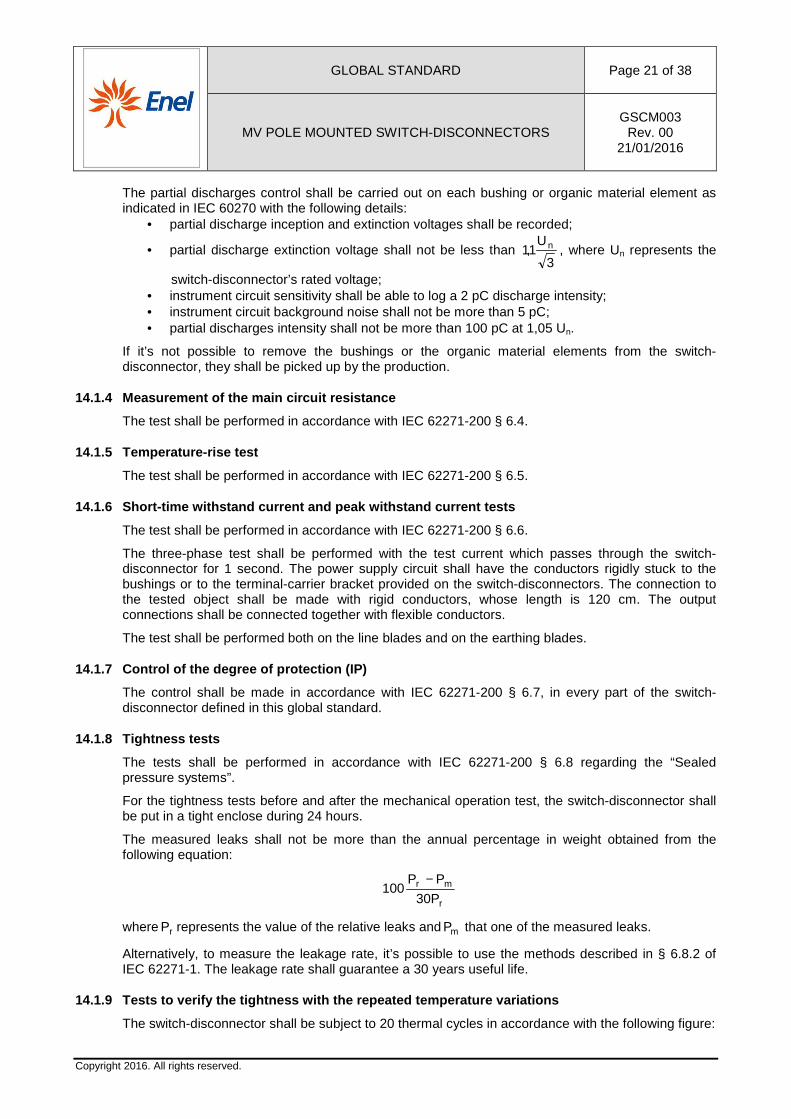
14.1.9 Tests to verify the tightness with the repea ted temperature variations
The switch-disconnector shall be subject to 20 thermal cycles in accordance with the following figure:
MV POLE MOUNTED SWITCH
Copyright 2016. All rights reserved.
Figure 1: Thermal cycles to verify the tightness with the repeated te mperature variations
After 6 hours and 18 hours performed on the switch-disconnectorcarried out with the following way
• one measurement at ambient temperature at the beginning and at the end of the test, in accordance with paragraph
At the end of the 20 cycles, leakobtained from the equation pointed out in paragraph
14.1.10 Additional test on auxiliary and control circuits
The test shall be performed in accordance with IEC 62271
14.1.11 Making and b reaking tests
The test shall be performed in accordance with standards:
• switch-disconnectors• earthing switches: IEC 62271
The tests include: • verification of the rated • verification of the rated • verification of the rated • verification of the rated • verification of the rated short
The tests shall be carried out
Regarding the tests with no-• the power supply circuit is the same of the one used in the test with mainly active loads;• the load circuit shall be composed by a transformer with the secondary winding closed on a
proper reactance; • the power factor shall be less than 0.1; the circuit natural frequency shall have a value
between 100 Hz and 200 Hz; the damping ratio shall have a value between 0.15
The test cycle shall provide the execution of 100 opening operations • 50 operations with a current between
breaking capability;
GLOBAL STANDARD
MV POLE MOUNTED SWITCH-DISCONNECTORS
cycles to verify the tightness with the repeated te mperature variations
After 6 hours and 18 hours from the beginning of each of the 20 cycles, 2 Cdisconnector (IMS + ST). Verifications for the leaks
the following way: one measurement at ambient temperature at the beginning and at the end of the test, in accordance with paragraph 14.1.8.
At the end of the 20 cycles, leakages must not be more than the annual peobtained from the equation pointed out in paragraph 14.1.8.
Additional test on auxiliary and control circuits
The test shall be performed in accordance with IEC 62271-200 § 6.10.
reaking tests
The test shall be performed in accordance with IEC 62271-200 § 6.101 and with the specific
disconnectors: IEC 62271-103 § 6.101 switches: IEC 62271-102 § 6.101
verification of the rated normal breaking current on a mainly active load;rated normal breaking current on a no-load transformer;rated normal breaking current on no-load lines; rated normal breaking current on no-load cables;
the rated short-circuit making current.
The tests shall be carried out on one switch-disconnector.
-load transformer: the power supply circuit is the same of the one used in the test with mainly active loads;
ll be composed by a transformer with the secondary winding closed on a
the power factor shall be less than 0.1; the circuit natural frequency shall have a value between 100 Hz and 200 Hz; the damping ratio shall have a value between 0.15
The test cycle shall provide the execution of 100 opening operations as followrations with a current between 20% and 40% of the no
Page 22 of 38
GSCM003 Rev. 00
21/01/2016
cycles to verify the tightness with the repeated te mperature variations
2 C-O operations must be leaks determination shall be
one measurement at ambient temperature at the beginning and at the end of the test, in
not be more than the annual percentage in weight
200 § 6.101 and with the specific
on a mainly active load; load transformer;
the power supply circuit is the same of the one used in the test with mainly active loads; ll be composed by a transformer with the secondary winding closed on a
the power factor shall be less than 0.1; the circuit natural frequency shall have a value between 100 Hz and 200 Hz; the damping ratio shall have a value between 0.15 and 0.25.
as follow: the no-load transformer rated
GLOBAL STANDARD Page 23 of 38
MV POLE MOUNTED SWITCH-DISCONNECTORS GSCM003
Rev. 00 21/01/2016
Copyright 2016. All rights reserved.
• 50 operations with a current between 80% and 100% of the no-load transformer rated making capability.
The maximum permissible over-voltage is 3.5 p.u. towards the earth and 4.5 p.u. between phases13.
To verify the making capability, the test cycle includes making operations with a 3 minutes interval.
14.1.12 Mechanical endurance test
The test shall be performed in accordance with IEC 62271-200 § 6.102.
The switch-disconnector’s mechanical operation test shall be performed in accordance with IEC 62271-103 § 6.102, whereas the earthing switches’ one in accordance with IEC 62271.102 § 6.102.
At the beginning of the tests, the recording of the opening and closing contacts movement shall be performed on all the samples submitted by the manufacturer: the average speeds of the contacts, from the moment of their separation to that one in which they have made the 25% of their travel and from the moment in which they arrive at the 75% of their travel14 to that of their connection, shall not differ more than ±5% on five specimens.
After the execution of 5000 operations, the recording of the contacts movement shall be repeated on the tested specimen: the already defined average speeds of the contacts, at the moment of separation and connection, observed at the end of the tests, shall not differ more than 5% than those ones observed at the beginning of the tests.
If the tested object has got earthing blades, the following tests shall be performed too: • execution of 1000 complete opening and closing operations on the earthing blades; • verification of the interlock between the line blades and the earthing blades
• through the execution of 50 complete opening and closing operations on alternated earthing blades and line blades;
• if the interlock doesn’t forbid the earthing switch operation with switch-disconnector in closed position. In case of switch-disconnectors with manual command, there shall be a 40 Nm moment on the earthing blades command shaft with the line blades closed and, subsequently, on the line blades command shaft with the earthing blades closed; in case of switch-disconnectors with electric or pneumatic command, it must be verified that, with the earthing blades closed, operating those commands, it’s impossible to close the line blades operating on them.
At the end of the tests, the switch-disconnector must work perfectly.
14.1.13 Pressure withstand test for gas-filled comp artments
The test shall be performed in accordance with IEC 62271-200 § 6.103.
14.1.14 Tests for organic material insulating eleme nts
The insulator shall pass all the tests of the standard IEC 62217. The only exception is the electrical environmental ageing test, as stated in paragraph 9.3.3 of IEC 62217, which shall have a duration of 5000 hours.
The 5000 hours electrical environmental ageing tests may be done on insulators put in the switch-disconnector or on single insulators. In the case that single insulators have been tested, the whole switch-disconnector must pass the test of paragraph 9.3.3 of IEC 62217 with a duration of 500 hours.
13 Values p.u. referred to 3
2U, where U is the real phase-to-phase testing voltage
14 The travel is measured as a straight line distance between the closed and open position of the arcing contact

MV POLE MOUNTED SWITCH
Copyright 2016. All rights reserved.
14.1.15 Verification of the protection against rust
At the end of the previous paragraph testmoreover no trace of rust shall besome traces of rust are allowedarea affected by rust cannot lead to a decrease in strength or effectiveness of the disconnector.
14.1.16 Internal arc test
The test shall be performed in accordance withapproach distance of 3 m.
14.1.17 Verification of switch- disconnector
The switch-disconnector and the earthing switch shall be tested in accordance with points A.6.105.1.3 and A.6.105.2 A.6.105.3 of the same standard.
14.1.18 Mechanical strength test
On a complete switch-disconnector• lifting test: the switch
250 kg mass, uniformly• strain test: the test consists in securing the
and applying 1000 N on each of the two eyebolts, 5 minutes. The test must be repeated applying the same 1000 N in accordance with the following Fig. 2.
After having completed the tests, roof’s vertical, shall not be present. All the elapplying a 200 Nm maximum moment.
14.1.19 Test of the kinematic chain in
In addition to the test in A.6.105.1.3 of IEC 62271disconnectors which have one or more phases in a different position from those one indicated in the signal device, for their constructive features, in case one or more elements of the kinematic chain break, shall be subject to a test in order to verify, during the homolthe kinematic chain itself in an abnormal working condition during the type tests repetition.
The test shall be performed, on one switchobstruction at the end of the main contacts travel, before they reach both the open position (or earthing position in case of three positions switch
GLOBAL STANDARD
MV POLE MOUNTED SWITCH-DISCONNECTORS
Verification of the protection against rust
previous paragraph test, the switch-disconnector must be able to function shall be on the joints, washers, screws, and/or similar pieces. However,
are allowed on large pieces when it is clear that any possible area affected by rust cannot lead to a decrease in strength or effectiveness of the
The test shall be performed in accordance with IEC 62271-200 § 6.106
disconnector and earthing switches’ safe devices
disconnector and the earthing switch shall be tested in accordance with points A.6.105.2 of IEC 62271-102. These tests are positive if they comply with po
.6.105.3 of the same standard.
disconnector, the following tests shall be performed: switch-disconnector shall be lifted through the two eyebolts with an additional
250 kg mass, uniformly distributed on the bottom and kept lifted during strain test: the test consists in securing the switch-disconnector to the floor through four bolts and applying 1000 N on each of the two eyebolts, as indicated in the following
. The test must be repeated applying the same 1000 N in accordance with the
After having completed the tests, permanent strains greater than 3 mm, measured at the base of the , shall not be present. All the electric and mechanical systems shall work perfectly
applying a 200 Nm maximum moment.
est of the kinematic chain in an abnormal working condition
In addition to the test in A.6.105.1.3 of IEC 62271-102 to verify the safe position, the switchwhich have one or more phases in a different position from those one indicated in the
signal device, for their constructive features, in case one or more elements of the kinematic chain break, shall be subject to a test in order to verify, during the homologation process, the reliability of the kinematic chain itself in an abnormal working condition during the type tests repetition.
The test shall be performed, on one switch-disconnector and before closing the shell, by realif the main contacts travel, before they reach both the open position (or
earthing position in case of three positions switch-disconnectors) and the close position.
Page 24 of 38
GSCM003 Rev. 00
21/01/2016
must be able to function perfectly; on the joints, washers, screws, and/or similar pieces. However,
possible development of the area affected by rust cannot lead to a decrease in strength or effectiveness of the switch-
considering a minimum
and earthing switches’ safe devices
disconnector and the earthing switch shall be tested in accordance with points 102. These tests are positive if they comply with point
shall be lifted through the two eyebolts with an additional distributed on the bottom and kept lifted during five minutes;
to the floor through four bolts as indicated in the following Fig. 1, during
. The test must be repeated applying the same 1000 N in accordance with the
permanent strains greater than 3 mm, measured at the base of the ectric and mechanical systems shall work perfectly
102 to verify the safe position, the switch-which have one or more phases in a different position from those one indicated in the
signal device, for their constructive features, in case one or more elements of the kinematic chain ogation process, the reliability of
the kinematic chain itself in an abnormal working condition during the type tests repetition.
disconnector and before closing the shell, by realising an f the main contacts travel, before they reach both the open position (or
disconnectors) and the close position.
MV POLE MOUNTED SWITCH
Copyright 2016. All rights reserved.
Testing modalities shall be indicated by the manufacturer, submitting them to Companies approval that will endorse the documentation in order to ensure the repeatability.
With the command or equivalent system and in order to stress all the elements of the chain, the test shall be realized by applying on the same obstruction and tand a possible moment M of 1.5 times the value defined by the manufacturer during the design, as indicated by the above-mentioned standard.
The test can be considered positive if no breaks occur.
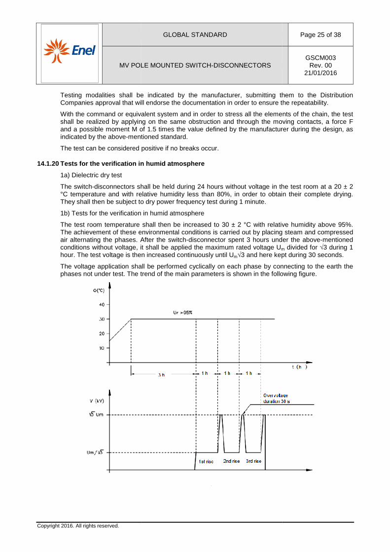
14.1.20 Tests for the verifica tion in humid atmosphere
1a) Dielectric dry test
The switch-disconnectors shall be held during 24 hours without voltage in the test room at a 20 ± 2 °C temperature and with relative humidity less than 80%, in order to obtain their complete drying. They shall then be subject to dry power frequency test during 1 minute.
1b) Tests for the verification in humid atmosphere
The test room temperature shall then be increased to 30 ± 2 °C with relative humidity above 95%. The achievement of these environmental air alternating the phases. After the switchconditions without voltage, it shall be applied the maximum rated voltage Uhour. The test voltage is then increased continuously until U
The voltage application shall be performed cyclically on each phase by connecting to the earth the phases not under test. The trend o
GLOBAL STANDARD
MV POLE MOUNTED SWITCH-DISCONNECTORS
Testing modalities shall be indicated by the manufacturer, submitting them to approval that will endorse the documentation in order to ensure the repeatability.
With the command or equivalent system and in order to stress all the elements of the chain, the test shall be realized by applying on the same obstruction and through the moving contacts, a force F and a possible moment M of 1.5 times the value defined by the manufacturer during the design, as
mentioned standard.
The test can be considered positive if no breaks occur.
tion in humid atmosphere
disconnectors shall be held during 24 hours without voltage in the test room at a 20 ± 2 °C temperature and with relative humidity less than 80%, in order to obtain their complete drying.
ll then be subject to dry power frequency test during 1 minute.
1b) Tests for the verification in humid atmosphere
The test room temperature shall then be increased to 30 ± 2 °C with relative humidity above 95%. The achievement of these environmental conditions is carried out by placing steam and compressed air alternating the phases. After the switch-disconnector spent 3 hours under the aboveconditions without voltage, it shall be applied the maximum rated voltage Um
hour. The test voltage is then increased continuously until Um√3 and here kept during 30 seconds.
The voltage application shall be performed cyclically on each phase by connecting to the earth the phases not under test. The trend of the main parameters is shown in the following figure.
Page 25 of 38
GSCM003 Rev. 00
21/01/2016
Testing modalities shall be indicated by the manufacturer, submitting them to the Distribution approval that will endorse the documentation in order to ensure the repeatability.
With the command or equivalent system and in order to stress all the elements of the chain, the test hrough the moving contacts, a force F
and a possible moment M of 1.5 times the value defined by the manufacturer during the design, as
disconnectors shall be held during 24 hours without voltage in the test room at a 20 ± 2 °C temperature and with relative humidity less than 80%, in order to obtain their complete drying.
The test room temperature shall then be increased to 30 ± 2 °C with relative humidity above 95%. conditions is carried out by placing steam and compressed
disconnector spent 3 hours under the above-mentioned m divided for √3 during 1
3 and here kept during 30 seconds.
The voltage application shall be performed cyclically on each phase by connecting to the earth the f the main parameters is shown in the following figure.
GLOBAL STANDARD Page 26 of 38
MV POLE MOUNTED SWITCH-DISCONNECTORS GSCM003
Rev. 00 21/01/2016
Copyright 2016. All rights reserved.
14.1.21 Tests to verify the effectiveness of the pr otection against pollution
Referring to point 5.102 of IEC 62271-102, in the absence of a safe connection to earth, to verify the effectiveness of the protection against pollution in service of the insulating materials, it shall be performed the following test:
1) with the switch-disconnector isolated, it shall be applied a 60 kV power frequency voltage (for 24 kV switch-disconnector) or 80 kV power frequency voltage (for 36 kV switch-disconnector) between inlet and outlet, measuring the leakage current.15
2) the switch-disconnector is then subject to the following cycle, that simulates a 10 years electrical service life to be repeated 3 times:
• 20 openings at 100 Arms and cosϕ = 0,7 • 8 closings at 4 kArms and cosϕ = 0,15 • 15 closings at 3 kArms and cosϕ = 0,15 • 10 openings at 100 Arms and cosϕ = 0,7 • 30 closings at 200 Arms and cosϕ = 0,7 • 37 closings at 2 kArms and cosϕ = 0,15 • 15 closings at 1 kArms and cosϕ = 0,15 • 15 openings at 100 Arms and cosϕ = 0,7
3) the switch-disconnector shall be tested in accordance with the previous point 1.
The test result is positive if there are no discharges on the sectioning and if the leakage current value doesn’t exceed 30 mA.
14.2 Additional type tests for switch-disconnectors with electrical command DC 24 V cc
In addition to type and routine tests, described in paragraphs 14.1 and 14.3, also the following tests shall be performed on the switch-disconnector with electrical command.
Tests from 14.2.1 to 14.2.8 must be performed in accordance with what specified in the following paragraphs and without voltage on the main circuits; the mechanical operation test, described in 14.1.12, shall be carried out with the variants and integrations provided in 14.2.4.
In details, after the test described in 14.2.4 (and possible 14.2.4.1), tests from 14.2.5 to 14.2.8 shall be performed on the same specimen and without maintenance.
14.2.1 Verification of the auxiliary circuits conne ctions
It shall be verified the correspondence of the connections to the electric scheme approved by the Distribution Company in accordance with the technical specifications DY1050.
14.2.2 Dielectric tests
Before beginning the tests, motor conductors and surge suppressors must be disconnected and properly isolated (leaving connected the possible coupling device).
14.2.3 Verification of electrical interlocks functi oning
The electrical command must be forbidden in the following conditions: • the earthing switch is not in open position; • the lever for the manual operation of the switch-disconnector’s blades is being inserted (the
prohibition must already act before the end of the lever engages on the tang of the operating shaft).
15 In case of a discharge towards the earth, the switch-disconnector shall be properly isolated towards the earth.
GLOBAL STANDARD Page 27 of 38
MV POLE MOUNTED SWITCH-DISCONNECTORS GSCM003
Rev. 00 21/01/2016
Copyright 2016. All rights reserved.
Particular attention shall be put to verify the interlocks functioning in case a supply interruption occurs when the mechanism is close to the deadcenter, so immediately before the switch-disconnector could be operated.
14.2.4 Mechanical operation tests with electrical c ommand
The switch-disconnector shall be subject to 5000 C-O operating cycles, as indicated in 14.1.12, under the following conditions:
Number of cycles Temperature [°C] Voltage [Vcc]
1250 50 28,8
1250 50 19,2
1250 -25 * 19,2
1250 -25 28,8
* For Romania it shall be considered the temperature of -40 °C.
The 1250 cycles shall be performed with 1 cycle every 30 seconds.
All the operations shall be realized sending command impulses ≤ 300 ms.
At the end of the 5000 cycles, other 100 cycles shall be made with manual command and at ambient temperature.
Before and after the mechanical operation tests, the average speed of the contacts shall be measured in accordance with the requirements in 14.1.12.
At the end of the mechanical operation tests, opening and closing operating times shall be recorded, together with the motor and the possible coupling device absorption; the obtained values shall not differ more than ±10% respect those ones obtained during the test in 14.2.5.
14.2.4.1 Mechanical operation tests with motor entrainment
Before the operations with electrical command described in the previous paragraph, if during the electrical operation the motor is completely or partially drag (excluding the first operation), 100 manual operations shall be made on the switch-disconnector, recording the absorption before and after so as to verify that there are no damages.
14.2.5 Characteristics of the electrical command
Opening and closing operating times shall be recorded, together with the absorbed power at minimum, rated and maximum supply voltage.
For the possible coupling device, only the absorbed power shall be recorded at miminum, nominal and maximum values.
For the other electrical components used on the electrical command, the manufacturer shall give specific documentation in accordance with this global standard. The Distribution Companies reserve the right to prescribe additional tests.
GLOBAL STANDARD Page 28 of 38
MV POLE MOUNTED SWITCH-DISCONNECTORS GSCM003
Rev. 00 21/01/2016
Copyright 2016. All rights reserved.
14.2.6 Interruption and subsequent electrical opera ting completion
After having caused a supply interruption during opening and closing operations, it must be verified that there aren’t anomalies during the subsequent electrical operating cycles (3 O-C and 3 C-O).
14.2.7 Interruption and subsequent manual operating completion
After having caused a supply interruption during opening and closing operations, it must be verified that there aren’t anomalies during the subsequent manual operating cycles (3 O-C and 3 C-O).
14.2.8 Verification of the enclosures’ degree of pr otection
It shall be verified the degree of protection (IEC 60529) on all the components used on the electrical command, whose characteristic has been specified in this global standard.
14.3 Routine tests
14.3.1 Visual inspection
It shall be performed on a random switch-disconnector among those ones that belong to the batch submitted to the commissioning.
The control shall be made comparing the constructive and dimensional features with those ones in the drawings and pictures approved by the Distribution Companies and kept by the manufacturer.
14.3.2 Dielectric test on main circuit
The test shall be performed in accordance with IEC 62271-200 § 7.1.
14.3.3 Tests on auxiliary and control circuits
The test shall be performed in accordance with IEC 62271-200 § 7.2.
14.3.4 Measurement of the resistance of the main ci rcuit
The test shall be performed in accordance with IEC 62271-200 § 7.3.
14.3.5 Mechanical operation tests
The test shall be performed in accordance with IEC 62271-200 § 7.102.
The contact speeds, measured as indicated in 14.1.12, shall not differ more than ±10% from the average values obtained during the type tests for the homologation of the products.
14.3.6 Partial discharge measurement
The manufacturer shall provide appropriate documentation stating the regular partial discharge test during the own production cycles. The Distribution Companies reserve the right to perform additional tests on organic material elements taken during the production process.
14.3.7 Tightness tests
The manufacturer shall self-certify the measure on each switch-disconnector, as indicated in IEC 62271-200 § 7.4.
14.4 Additional routine tests for switch-disconnect ors with electrical command DC 24 V cc
Tests from 14.4.1 to 14.4.8 shall be performed in accordance with the following modalities and without voltage on main circuits.
GLOBAL STANDARD Page 29 of 38
MV POLE MOUNTED SWITCH-DISCONNECTORS GSCM003
Rev. 00 21/01/2016
Copyright 2016. All rights reserved.
Mechanical operation test, described in 14.3.5, shall be made under the conditions stated in 14.4.4; in detail, tests from 14.4.6 to 14.4.8 shall be performed, after that test, on the same specimens and without maintenance.
14.4.1 Verification of auxiliary circuits connectio ns
As indicated in 14.2.1, the same tests shall be performed on the sampling.
14.4.2 Dielectric tests
The tests shall be performed with the same modalities described in 14.2.2.
14.4.3 Verification of electrical interlocks functi oning
The tests shall be performed with the same modalities described in 14.2.3.
14.4.4 Mechanical operation tests on the electrical command
The switch-disconnector shall be subject to 20 electrical C-O cycles at ambient temperature, 10 at maximum voltage and 10 at minimum voltage, one every minute. The main contacts speeds shall not differ more than ±10% from the average values obtained during the homologation tests.
After having completed the 20 cycles with the electrical command, other 2 shall be performed with manual command.
14.4.5 Characteristics of the electrical command
The tests shall be performed on one specimen of the sampling, with the same modalities indicated in 14.2.5.
14.4.6 Interruption and subsequent electrical opera ting completion
The test shall be made for 2 C-O cycles with the same modalities indicated in 14.2.6.
14.4.7 Interruption and subsequent manual operating completion
The test shall be made for 2 C-O cycles with the same modalities indicated in 14.2.7.
14.4.8 Verification of the enclosures’ degree of pr otection
On one specimen of the sampling, it shall be verified the degree of protection of the shell and enclosures, in accordance with 14.2.8.
14.5 Routine tests plan
All the routine tests indicated in the following table shall be carried out by the supplier on all the samples prepared for the commissioning. For each piece that belongs to the prepared batch, the supplier shall prepare a test report with the results of the tests performed.
The test, under the Distribution Companies surveillance, shall be carried out on a sample chosen randomly among those ones of the batch that has already been successfully tested by the supplier. The tests shall be carried out on samples defined by the sampling plan below.
At the end of the commissioning, within the measurement uncertainty, there shall not be differences between the measured values and those ones in the acceptation ranges of the approved test values.
In case of commissioning attended by the Distribution Companies, the entire batch will be rejected if the results of one of any test is negative.
GLOBAL STANDARD Page 30 of 38
MV POLE MOUNTED SWITCH-DISCONNECTORS GSCM003
Rev. 00 21/01/2016
Copyright 2016. All rights reserved.
A 1 sample for type
B Sampling plan: reduced, LQA = 0,65 level II (in case of negative result, in the new commissioning the sampling plan shall be ordinary)
D documentation check
Table 7: Sampling plan
N. TEST Reference Sampling plan
1 Visual inspection (a) 14.3.1 A
2 Dielectric test on main circuit (e) 14.3.2 B
3 Tests on auxiliary and control circuits 14.3.3 B
4 Measurement of the resistance of the main circuit (d) 14.3.4 B
5 Mechanical operation tests (c) 14.3.5 B
6 Partial discharge measurement 14.3.6 D
7 Tightness tests (f) 14.3.7 D
8 Verification of auxiliary circuits connections 14.4.1 B
9 Dielectric tests on auxiliary circuits connections (b) 14.4.2 B
10 Verification of electrical interlocks functioning 14.4.3 B
11 Mechanical operation tests on the electrical command 14.4.4 A
12 Characteristics of the electric command 14.4.5 A
13 Interruption and subsequent electrical operating completion 14.4.6 B
14 Interruption and subsequent manual operating completion 14.4.7 B
15 Verification of the enclosures’ degree of protection 14.4.8 A
Table 8: Testing plan
a Including the verification of the enclosures’ degree of protection (IP) b 2 kV power frequency testing voltage during 60 seconds c • On the earthing switches and on the switch-disconnector, 5 closing operations and 5 opening operations verifying the
mechanical interlocks functioning (IEC 62271-200 § 7.102). On the earthing switches it shall be measured the main contacts closing speed during the last operation.
• On the switch-disconnector mechanical operation tests shall be realised in accordance with IEC 62271-103 § 7.101. In case of electrical command, the maximum voltage shall be Vmax (28,8 Vcc) and the minimum one Vmin (19,2 Vcc). It shall be recorded the opening and closing main contacts speed only during the last operation of every sequence. During all the operations, all the electrical interlocks shall be verified ( § 14.4.3).
d Test to be performed on the same configuration used during the homologation process. e The test shall be performed with the operating devices closed and on the sectioning distance.
All the tests shall be performed at a 50 kV power frequency voltage (for 24 kV switch-disconnector) or 70 kV power frequency voltage (for 36 kV switch-disconnector).
f Test to be certified on single units by the supplier
Table 9: Additional information
GLOBAL STANDARD Page 31 of 38
MV POLE MOUNTED SWITCH-DISCONNECTORS GSCM003
Rev. 00 21/01/2016
Copyright 2016. All rights reserved.
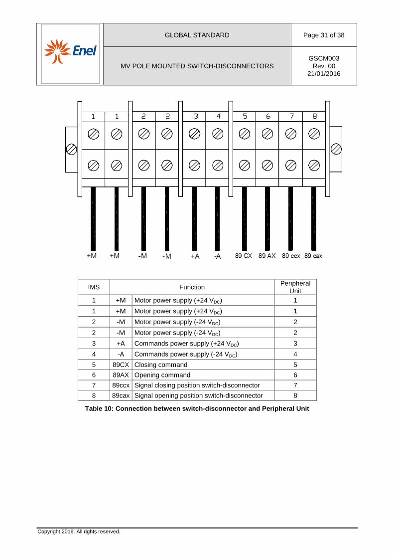
IMS Function Peripheral
Unit 1 +M Motor power supply (+24 VDC) 1
1 +M Motor power supply (+24 VDC) 1
2 -M Motor power supply (-24 VDC) 2
2 -M Motor power supply (-24 VDC) 2
3 +A Commands power supply (+24 VDC) 3
4 -A Commands power supply (-24 VDC) 4
5 89CX Closing command 5
6 89AX Opening command 6
7 89ccx Signal closing position switch-disconnector 7
8 89cax Signal opening position switch-disconnector 8
Table 10: Connection between switch-disconnector an d Peripheral Unit
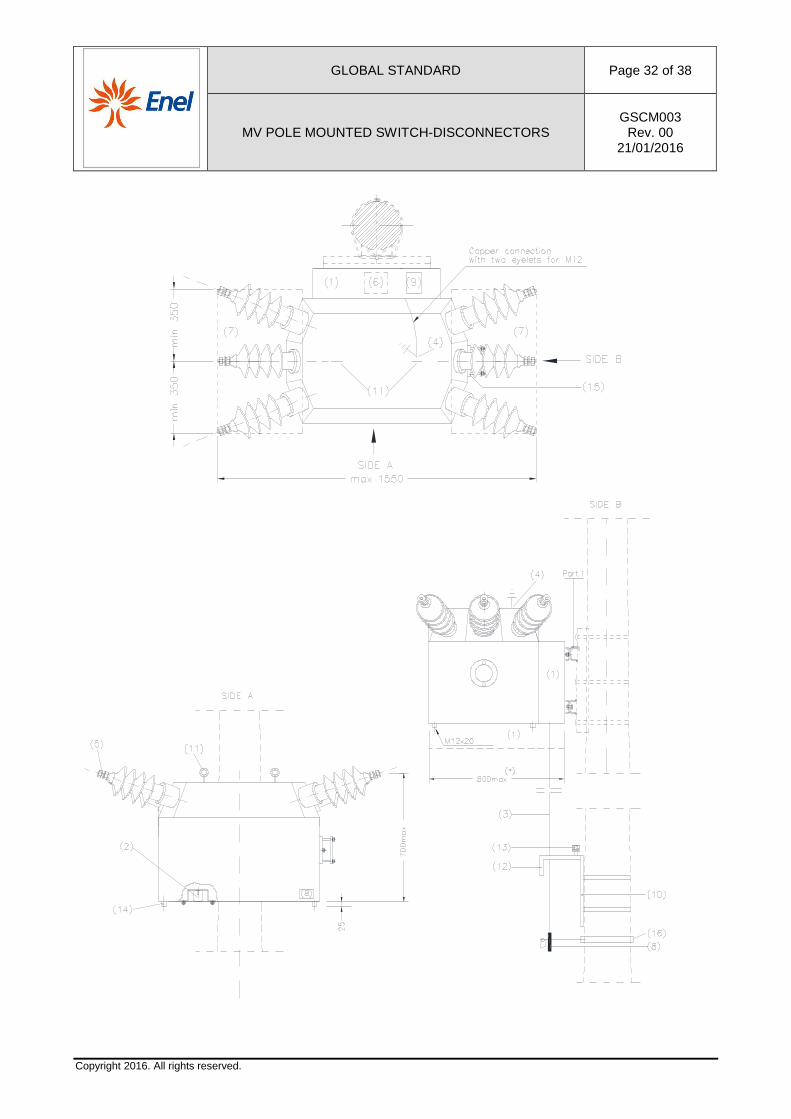
GLOBAL STANDARD Page 32 of 38
MV POLE MOUNTED SWITCH-DISCONNECTORS GSCM003
Rev. 00 21/01/2016
Copyright 2016. All rights reserved.
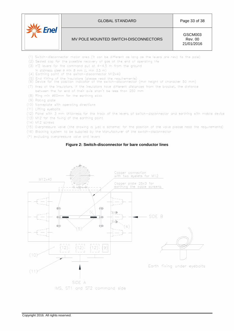
GLOBAL STANDARD Page 33 of 38
MV POLE MOUNTED SWITCH-DISCONNECTORS GSCM003
Rev. 00 21/01/2016
Copyright 2016. All rights reserved.
Figure 2: Switch-disconnector for bare conductor li nes
GLOBAL STANDARD Page 34 of 38
MV POLE MOUNTED SWITCH-DISCONNECTORS GSCM003
Rev. 00 21/01/2016
Copyright 2016. All rights reserved.
Figure 3: Switch-disconnector for cable lines
GLOBAL STANDARD Page 35 of 38
MV POLE MOUNTED SWITCH-DISCONNECTORS GSCM003
Rev. 00 21/01/2016
Copyright 2016. All rights reserved.
ANNEX A
The Manufacturer shall specify, in detail, data and information listed below.
General part
• Overall dimensional drawing with: • switch-disconnector and earthing switches position of the operating devices; • position and distance of the MV insulators and/or bushings; • dimension and position of the safety valve against overpressure; • position of the earthing point;
• Single-line electrical scheme of the main circuits and functional scheme of the auxiliary circuits.
• Drawing of the rating plate with the indication of the name given by the Manufacturer. • Maintenance plan, pointing out the characteristics of the resources to be used (people, lifting
machines, plant for gas treatment, special tools, etc.). • SF6 pressure at 20 °C:
• pr: filling pressure to be verified during routine tests; • pm: minimum necessary pressure to ensure the prescribed characteristics; • intervention pressure of the safety valve against overpressure.
• Documentation to demonstrate the dielectric strength of the protective shell of the switch-disconnector for the arc dispersion products.
• Characteristics of the resin used for the insulators and/or bushings. • List of type A and B documentation (public general drawings and reserved drawings). • Photos of the switch-disconnector. • Drawing of the installation layout of the switch-disconnector and its connections. • Test reports.
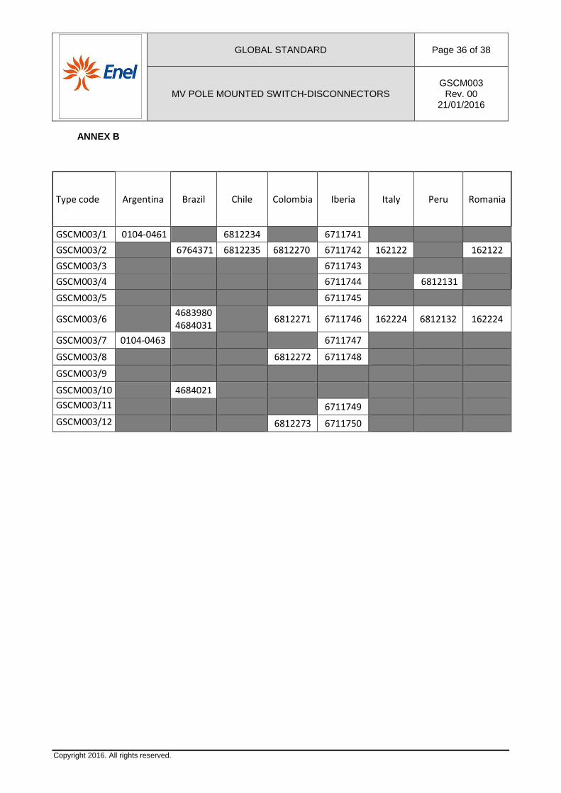
GLOBAL STANDARD Page 36 of 38
MV POLE MOUNTED SWITCH-DISCONNECTORS GSCM003
Rev. 00 21/01/2016
Copyright 2016. All rights reserved.
ANNEX B
Type code Argentina Brazil Chile Colombia Iberia Italy Peru Romania
GSCM003/1 0104-0461 6812234 6711741
GSCM003/2 6764371 6812235 6812270 6711742 162122 162122
GSCM003/3 6711743
GSCM003/4 6711744
6812131
GSCM003/5 6711745
GSCM003/6 4683980
4684031 6812271 6711746 162224 6812132 162224
GSCM003/7 0104-0463
6711747
GSCM003/8
6812272 6711748
GSCM003/9
GSCM003/10 4684021
GSCM003/11
6711749
GSCM003/12
6812273 6711750
GLOBAL STANDARD Page 37 of 38
MV POLE MOUNTED SWITCH-DISCONNECTORS GSCM003
Rev. 00 21/01/2016
Copyright 2016. All rights reserved.
ANNEX C
This form is used for evaluating the offer in the tender process and also for the technical data validation during the homologation, certification and approval procedure.
Flag here the use of this form: Offer in the Tender
Technical Data Validation
This document has to be used for checking the compliance of the switch-disconnector during the tender process.
Deviations are in principle not acceptable.
Possible deviations have to be clearly reported in the following form for specific deviations.
The acceptance of this document for the next tender stage does not mean the acceptance of any deviation to the technical specification if such deviations are not clearly reported in the form for specific deviations.
GLOBAL STANDARD Page 38 of 38
MV POLE MOUNTED SWITCH-DISCONNECTORS GSCM003
Rev. 00 21/01/2016
Copyright 2016. All rights reserved.
FORM FOR SPECIFIC DEVIATIONS
Each specific deviation shall be reported and explained here below (to be indicated with a progressive number).
NO DEVIATIONS
(to flag in case of no deviations from the Global Standard)
DEVIATION 1
[To indicate possible Deviation
……………………………………………………………………………………………………………………………………………………………………………………………………………………………………………………………………………………………………………………………………………………………………………………………………………………………………………………………………………………………………………………………………………………………………………………………………………………………………………………………………………………………………………....................]
DEVIATION 2
[To indicate possible Deviation
……………………………………………………………………………………………………………………………………………………………………………………………………………………………………………………………………………………………………………………………………………………………………………………………………………………………………………………………………………………………………………………………………………………………………………………………………………………………………………………………………………………………………………………………]
DEVIATION …
[To indicate possible Deviation
……………………………………………………………………………………………………………………………………………………………………………………………………………………………………………………………………………………………………………………………………………………………………………………………………………………………………………………………………………………………………………………………………………………………………………………………………………………………………………………………………………………………………………………………]
Date […………………………………….]
Sign […………………………………….]